Transient power stabilization device with active and reactive power control
Yang , et al. Feb
U.S. patent number 10,574,055 [Application Number 15/539,772] was granted by the patent office on 2020-02-25 for transient power stabilization device with active and reactive power control. This patent grant is currently assigned to Flexgen Power Systems, Inc.. The grantee listed for this patent is Flexgen Power Systems, Inc.. Invention is credited to Gopalakrishnan Balakrishnan, Robert William Johnson, Jr., Tony Olivo, Pasi Taimela, Mengbin Yang.


| United States Patent | 10,574,055 |
| Yang , et al. | February 25, 2020 |
Transient power stabilization device with active and reactive power control
Abstract
A system includes a converter configured to be coupled between an energy storage unit and a grid and a control circuit configured to detect frequency and voltage variations of the grid and to responsively cause the converter to transfer power and reactive components to and/or from the grid. The control circuit may implement a power control loop having an inner frequency control loop and a reactive component control loop having an inner voltage control loop. The control circuit may provide feedforward from the inner frequency control loop to the inner voltage control loop to inhibit reactive component transfer in response to a voltage variation deviation of the grid due to a power transfer between the energy storage unit and the grid.
| Inventors: | Yang; Mengbin (Raleigh, NC), Taimela; Pasi (Wake Forest, NC), Olivo; Tony (Raleigh, NC), Johnson, Jr.; Robert William (Raleigh, NC), Balakrishnan; Gopalakrishnan (Katy, TX) | ||||||||||
|---|---|---|---|---|---|---|---|---|---|---|---|
| Applicant: |
|
||||||||||
| Assignee: | Flexgen Power Systems, Inc.
(Houston, TX) |
||||||||||
| Family ID: | 56284943 | ||||||||||
| Appl. No.: | 15/539,772 | ||||||||||
| Filed: | December 22, 2015 | ||||||||||
| PCT Filed: | December 22, 2015 | ||||||||||
| PCT No.: | PCT/US2015/067347 | ||||||||||
| 371(c)(1),(2),(4) Date: | June 26, 2017 | ||||||||||
| PCT Pub. No.: | WO2016/109330 | ||||||||||
| PCT Pub. Date: | July 07, 2016 |
Prior Publication Data
| Document Identifier | Publication Date | |
|---|---|---|
| US 20180013288 A1 | Jan 11, 2018 | |
Related U.S. Patent Documents
| Application Number | Filing Date | Patent Number | Issue Date | ||
|---|---|---|---|---|---|
| 62097691 | Dec 30, 2014 | ||||
| Current U.S. Class: | 1/1 |
| Current CPC Class: | H02J 3/24 (20130101); H02J 3/32 (20130101); H02J 3/28 (20130101); H02J 3/1842 (20130101); H02J 3/46 (20130101); H02J 3/18 (20130101); H02J 2300/10 (20200101); Y02E 40/22 (20130101); H02J 3/381 (20130101); Y02E 40/20 (20130101) |
| Current International Class: | H02J 1/10 (20060101); H02J 3/24 (20060101); H02J 3/46 (20060101); H02J 3/32 (20060101); H02J 3/18 (20060101); H02J 3/06 (20060101) |
References Cited [Referenced By]
U.S. Patent Documents
| 4992920 | February 1991 | Davis |
| 5327336 | July 1994 | Ohkubo |
| 5563802 | October 1996 | Plahn et al. |
| 5734205 | March 1998 | Okamura et al. |
| 5907192 | May 1999 | Lyons et al. |
| 5929538 | July 1999 | O'Sullivan et al. |
| 6038118 | March 2000 | Guerra |
| 6104102 | August 2000 | Tsuji |
| 6128204 | October 2000 | Munro et al. |
| 6175217 | January 2001 | Da Ponte et al. |
| 6252753 | June 2001 | Bhargava |
| 6265851 | July 2001 | Brien et al. |
| 6317343 | November 2001 | Okamura et al. |
| 6703722 | March 2004 | Christensen |
| 6870279 | March 2005 | Gilbreth et al. |
| 6879053 | April 2005 | Welches et al. |
| 6958550 | October 2005 | Gilbreth et al. |
| 6969922 | November 2005 | Welches et al. |
| 7002260 | February 2006 | Stahlkopf |
| 7116010 | October 2006 | Lasseter et al. |
| 7184903 | February 2007 | Williams et al. |
| 7391126 | June 2008 | Liu et al. |
| 7474016 | January 2009 | Wang et al. |
| 7476987 | January 2009 | Chang |
| 7514808 | April 2009 | Wobben |
| 7560906 | July 2009 | Liu et al. |
| 7612466 | November 2009 | Skutt |
| 7642755 | January 2010 | Bartilson |
| 7675187 | March 2010 | Woods et al. |
| 7680562 | March 2010 | Delmerico et al. |
| 7701087 | April 2010 | Eckroad et al. |
| 7781902 | August 2010 | Cerney et al. |
| 7787272 | August 2010 | Lasseter et al. |
| 7834479 | November 2010 | Capp et al. |
| 7855467 | December 2010 | Kawazoe et al. |
| 7906862 | March 2011 | Donnelly et al. |
| 7969030 | June 2011 | Woods et al. |
| 8022572 | September 2011 | Vyas et al. |
| 8080898 | December 2011 | Fukuhara |
| 8099198 | January 2012 | Gurin |
| 8164217 | April 2012 | Miller |
| 8222756 | July 2012 | Koeneman et al. |
| 8227929 | July 2012 | Burra et al. |
| 8315745 | November 2012 | Creed |
| 8338987 | December 2012 | O'Brien et al. |
| 8452688 | May 2013 | Sharplin et al. |
| 8492913 | July 2013 | Koeneman et al. |
| 8498752 | July 2013 | Wells |
| 8532834 | September 2013 | Delong et al. |
| 8558510 | October 2013 | Moon |
| 8688281 | April 2014 | Viassolo et al. |
| 8751036 | June 2014 | Darden, II et al. |
| 8766474 | July 2014 | Carralero et al. |
| 8810066 | August 2014 | Moon |
| 8829698 | September 2014 | Koeneman et al. |
| 8831788 | September 2014 | Flynn et al. |
| 8849469 | September 2014 | Belady et al. |
| 8866334 | October 2014 | Donnelly et al. |
| 8922056 | December 2014 | Thisted |
| 8922062 | December 2014 | Johnson et al. |
| 8938323 | January 2015 | Lee |
| 8946916 | February 2015 | Tarnowski |
| 8946929 | February 2015 | Singh et al. |
| 8975767 | March 2015 | Algrain |
| 9026259 | May 2015 | Zadeh et al. |
| 9026260 | May 2015 | Thornley et al. |
| 9042141 | May 2015 | Yu et al. |
| 2002/0017822 | February 2002 | Umemura et al. |
| 2002/0190525 | December 2002 | Worden et al. |
| 2002/0198648 | December 2002 | Gilbreth et al. |
| 2003/0047209 | March 2003 | Yanai et al. |
| 2003/0080622 | May 2003 | Koenig |
| 2004/0051387 | March 2004 | Lasseter et al. |
| 2004/0084965 | May 2004 | Welches et al. |
| 2004/0240244 | December 2004 | Yamamoto |
| 2004/0245783 | December 2004 | Gilbreth et al. |
| 2005/0012395 | January 2005 | Eckroad et al. |
| 2005/0043859 | February 2005 | Tsai et al. |
| 2005/0077881 | April 2005 | Capp |
| 2005/0154499 | July 2005 | Aldridge et al. |
| 2005/0200133 | September 2005 | Wobben |
| 2006/0192433 | August 2006 | Fuglevand et al. |
| 2006/0192435 | August 2006 | Parmley |
| 2007/0024227 | February 2007 | Kunkel et al. |
| 2007/0182158 | August 2007 | Cerney et al. |
| 2007/0210652 | September 2007 | Tracy et al. |
| 2007/0228836 | October 2007 | Teichmann |
| 2007/0267871 | November 2007 | Gregory |
| 2008/0088183 | April 2008 | Eckroad et al. |
| 2008/0203734 | August 2008 | Grimes et al. |
| 2008/0211230 | September 2008 | Gurin |
| 2008/0278000 | November 2008 | Capp et al. |
| 2009/0024255 | January 2009 | Penzenstadler |
| 2009/0072623 | March 2009 | Liao |
| 2009/0086520 | April 2009 | Nishimura |
| 2009/0140576 | June 2009 | Yu et al. |
| 2009/0189456 | July 2009 | Skutt |
| 2009/0195074 | August 2009 | Buiel |
| 2009/0312885 | December 2009 | Buiel |
| 2010/0008119 | January 2010 | O'Brien et al. |
| 2010/0096918 | April 2010 | Sawada et al. |
| 2010/0138066 | June 2010 | Kong |
| 2010/0264739 | October 2010 | Errington |
| 2010/0270864 | October 2010 | Vyas |
| 2010/0292853 | November 2010 | McDonnell |
| 2010/0327800 | December 2010 | Reineccius |
| 2011/0060474 | March 2011 | Schmiegel et al. |
| 2011/0062708 | March 2011 | Prochaska et al. |
| 2011/0068631 | March 2011 | Roscoe |
| 2011/0080044 | April 2011 | Schmiegel |
| 2011/0115295 | May 2011 | Moon et al. |
| 2011/0118894 | May 2011 | Reineccius et al. |
| 2011/0133558 | June 2011 | Park |
| 2011/0140520 | June 2011 | Lee |
| 2011/0140648 | June 2011 | Lee |
| 2011/0144822 | June 2011 | Choi |
| 2011/0148195 | June 2011 | Lee |
| 2011/0148360 | June 2011 | Lee |
| 2011/0204720 | August 2011 | Ruiz |
| 2011/0227340 | September 2011 | Rozman |
| 2011/0248569 | October 2011 | Son et al. |
| 2011/0260546 | October 2011 | Hashizume et al. |
| 2011/0266871 | November 2011 | Thisted |
| 2011/0273022 | November 2011 | Dennis et al. |
| 2011/0309690 | December 2011 | West |
| 2012/0025614 | February 2012 | Taimela et al. |
| 2012/0029897 | February 2012 | Cherian et al. |
| 2012/0033473 | February 2012 | Scharf |
| 2012/0046798 | February 2012 | Orthlieb et al. |
| 2012/0068540 | March 2012 | Luo et al. |
| 2012/0080942 | April 2012 | Carralero et al. |
| 2012/0083927 | April 2012 | Nakamura et al. |
| 2012/0089261 | April 2012 | Kim |
| 2012/0143383 | June 2012 | Cooperrider et al. |
| 2012/0146412 | June 2012 | Harrison |
| 2012/0146423 | June 2012 | Bodewes et al. |
| 2012/0147637 | June 2012 | Petter |
| 2012/0166013 | June 2012 | Park et al. |
| 2012/0215368 | August 2012 | Sharma |
| 2012/0239215 | September 2012 | Timbus et al. |
| 2012/0267952 | October 2012 | Ballatine et al. |
| 2012/0283887 | November 2012 | Goldsmith et al. |
| 2012/0283890 | November 2012 | Fu et al. |
| 2012/0287690 | November 2012 | Paatero |
| 2012/0292992 | November 2012 | Williams |
| 2012/0323396 | December 2012 | Shelton et al. |
| 2013/0015703 | January 2013 | Rouse et al. |
| 2013/0035802 | February 2013 | Khaitan et al. |
| 2013/0041516 | February 2013 | Rockenfeller et al. |
| 2013/0043825 | February 2013 | Diedrichs et al. |
| 2013/0062953 | March 2013 | Nurmi |
| 2013/0088084 | April 2013 | Szu |
| 2013/0099581 | April 2013 | Zhou et al. |
| 2013/0116844 | May 2013 | McNally et al. |
| 2013/0141956 | June 2013 | Chiang et al. |
| 2013/0158901 | June 2013 | Sahinoglu et al. |
| 2013/0166084 | June 2013 | Sedighy et al. |
| 2013/0169309 | July 2013 | Bickel |
| 2013/0187454 | July 2013 | Timbus et al. |
| 2013/0238151 | September 2013 | Vaum et al. |
| 2013/0241495 | September 2013 | Min |
| 2013/0285446 | October 2013 | Chow et al. |
| 2013/0342020 | December 2013 | Blevins et al. |
| 2014/0025217 | January 2014 | Jin et al. |
| 2014/0032000 | January 2014 | Chandrashekhara |
| 2014/0058571 | February 2014 | Hooshmand et al. |
| 2014/0078625 | March 2014 | Zheng et al. |
| 2014/0084682 | March 2014 | Covic et al. |
| 2014/0088778 | March 2014 | Nguyen |
| 2014/0088781 | March 2014 | Kearns et al. |
| 2014/0097683 | April 2014 | Piyabongkarn et al. |
| 2014/0100705 | April 2014 | Shi et al. |
| 2014/0103655 | April 2014 | Burra et al. |
| 2014/0103724 | April 2014 | Wagoner |
| 2014/0103727 | April 2014 | Taimela |
| 2014/0103855 | April 2014 | Wolter |
| 2014/0129042 | May 2014 | Miner |
| 2014/0148960 | May 2014 | Bhageria et al. |
| 2014/0152110 | June 2014 | Sugimoto |
| 2014/0183949 | July 2014 | Murano |
| 2014/0188300 | July 2014 | Nguyen |
| 2014/0191507 | July 2014 | Holmberg et al. |
| 2014/0200722 | July 2014 | Bhavaraju |
| 2014/0214223 | July 2014 | Tsunoda et al. |
| 2014/0217826 | August 2014 | Oguchi et al. |
| 2014/0225457 | August 2014 | Elliott, II |
| 2014/0229031 | August 2014 | Amarin et al. |
| 2014/0249686 | September 2014 | Brainard et al. |
| 2014/0265596 | September 2014 | Yuan et al. |
| 2014/0292259 | October 2014 | Kim et al. |
| 2014/0306533 | October 2014 | Paquin et al. |
| 2014/0306534 | October 2014 | Shi et al. |
| 2014/0312882 | October 2014 | Dong et al. |
| 2014/0316593 | October 2014 | Taimela et al. |
| 2014/0324243 | October 2014 | Markowz et al. |
| 2014/0337002 | November 2014 | Manto |
| 2014/0354234 | December 2014 | Sudan et al. |
| 2014/0375125 | December 2014 | Ye et al. |
| 2015/0001931 | January 2015 | Banham-Hall et al. |
| 2015/0008737 | January 2015 | Mao |
| 2015/0019034 | January 2015 | Gonatas |
| 2015/0021998 | January 2015 | Trescases et al. |
| 2015/0032278 | January 2015 | Bhageria et al. |
| 2015/0039145 | February 2015 | Yang et al. |
| 2015/0081124 | March 2015 | Ekanayake et al. |
| 2015/0094871 | April 2015 | Bhageria et al. |
| 2015/0097437 | April 2015 | Votoupal et al. |
| 2015/0105931 | April 2015 | Forbes, Jr. |
| 2015/0109836 | April 2015 | Hatakeyama |
| 103 490 450 | Jan 2014 | CN | |||
| 3311299 | Oct 1984 | DE | |||
| 69 707 704 D1 | Nov 2001 | DE | |||
| 69 707 704 | Jun 2002 | DE | |||
| 10 2007 005352 | Aug 2007 | DE | |||
| 0 947 042 | Oct 2001 | EP | |||
| 1 638 184 | Mar 2006 | EP | |||
| 1 638 184 | Mar 2006 | EP | |||
| 2 251 953 | Nov 2010 | EP | |||
| 2 325 970 | May 2011 | EP | |||
| 2 330 726 | Jun 2011 | EP | |||
| 2 337 178 | Jun 2011 | EP | |||
| 2 337 184 | Jun 2011 | EP | |||
| 2 339 714 | Jun 2011 | EP | |||
| 2 380 769 | Oct 2011 | EP | |||
| 1 866 717 | Jun 2012 | EP | |||
| 2 782 204 | Sep 2014 | EP | |||
| 2 782 204 | Sep 2014 | EP | |||
| 2434928 | Aug 2007 | GB | |||
| 2434928 | Apr 2010 | GB | |||
| 2 483 879 | Mar 2012 | GB | |||
| 2001-507199 | May 2001 | JP | |||
| 2011-109901 | Jun 2011 | JP | |||
| WO 98/28832 | Jul 1998 | WO | |||
| WO 99/32762 | Jul 1999 | WO | |||
| WO 02/17475 | Feb 2002 | WO | |||
| WO 2004/038892 | May 2004 | WO | |||
| WO 2004/054065 | Jun 2004 | WO | |||
| WO 2005/101610 | Oct 2005 | WO | |||
| WO 2006/094128 | Sep 2006 | WO | |||
| WO 2007/018830 | Feb 2007 | WO | |||
| WO 2008/039725 | Apr 2008 | WO | |||
| WO 2008/125696 | Oct 2008 | WO | |||
| WO 2009/128079 | Oct 2009 | WO | |||
| WO 2009/144737 | Dec 2009 | WO | |||
| WO 2010/038152 | Apr 2010 | WO | |||
| WO 2010/042550 | Apr 2010 | WO | |||
| WO 2011/008505 | Jan 2011 | WO | |||
| WO 2011/008506 | Jan 2011 | WO | |||
| WO 2011/020149 | Feb 2011 | WO | |||
| WO 2011/124657 | Oct 2011 | WO | |||
| WO 2012/015508 | Feb 2012 | WO | |||
| WO 2012/064906 | May 2012 | WO | |||
| WO 2013/008413 | Jan 2013 | WO | |||
| WO 2013/008413 | Feb 2013 | WO | |||
| WO 2013/102791 | Jul 2013 | WO | |||
| WO 2013/102791 | Jul 2013 | WO | |||
| WO 2014/071948 | May 2014 | WO | |||
Other References
|
Anwar, et al., Supercapacitor Energy Storage for Low-Voltage Ride Through in a 13.8KV AC System, 2010 IEEE, pp. 189-192. cited by applicant . EPCC Electronic Power Control & Conditioning Module, Jan. 2010, www.nextenergy.org, 6 pages. cited by applicant . IEEE Spectrum: Circuit Could Swap Ultracapacitors for Batteries, http://spectrum.ieee.org/Semiconductors/design/circuit-could-swap-ultraca- pacitors-for-batter . . . , Jun. 21, 2010, 2 pages. cited by applicant . Kotz R. et al., "Principles and applications of electrochemical capacitors", Electrochimica Acta, vol. 45 (2000), pp. 2483-2498. cited by applicant . Nomoto S. et al., "Advanced capacitors and their application", Journal of Power Sources, 97-98 (2001), pp. 807-811. cited by applicant . Ultra Capacitor, Power Conditioning Solutions, Unirom Electronics Ltd., www.unirom.co.il, Printed Jun. 18, 2010, 8 pages. cited by applicant . Unirom Electronics Presentation, Semicon Japan 2008, pp. 1-30. cited by applicant . U.S. Appl. No. 14/190,398, filed Feb. 26, 2014 entitled "Hybrid Energy Storage System and Methods,". cited by applicant . U.S. Appl. No. 61/771,403, filed Mar. 1, 2013 entitled "Hybrid Energy Storage System and Methods,". cited by applicant . Notification Concerning Transmittal of International Preliminary Report on Patentability, PCT/US2015/067347, dated Jul. 4, 2017, 7 pages. cited by applicant . International Search Report and Written Opinion, PCT/US2015/067347, dated Mar. 7, 2017, 2 pages. cited by applicant . Extended European Search Report, EP 15 876 046.2, dated May 7, 2018, 11 pages. cited by applicant . Sato et al., Novel Control Strategy of Instantaneous Power Based CVCF Inverter, IEEE 7.sup.th International Conference on Power Electronics and Drive Systems, Nov. 27, 2007, pp. 1502-1507. cited by applicant . Communication pursuant to Article 94(3) EPC, EP 15 876 046.2, dated May 24, 2019, 6 pages. cited by applicant . Examination report No. 1 for standard patent application, AU Application No. 2015374405, dated May 29, 2019, 4 pages. cited by applicant . European Office Action, EP 15 876 046.2, dated Dec. 4, 2019, 3 pages. cited by applicant. |
Primary Examiner: Barnie; Rexford N
Assistant Examiner: Mourad; Rasem
Attorney, Agent or Firm: Stanek Lemon Crouse & Meeks, P.A.
Parent Case Text
RELATED APPLICATIONS
The present application is a 35 U.S.C. .sctn. 371 national phase application of PCT International Application No. PCT/US2015/067347, having an international filing date of Dec. 22, 2015, and claims the benefit of U.S. Provisional Application Ser. No. 62/097,691, filed Dec. 30, 2015, the contents of which are incorporated herein by reference in their entireties.
Claims
That which is claimed is:
1. A system comprising: a converter configured to be coupled between an energy storage unit and a grid; a converter controller configured to control the converter responsive to a real power command and a reactive power command that respectively cause the converter to transfer a real power component and a reactive power component; and a control circuit configured to detect frequency and voltage variations of the grid and to responsively generate the real power command and the reactive power command, wherein the control circuit implements: a real power control loop configured to generate the real power command responsive to a frequency of the grid and a real power reference; and a reactive power control loop configured to generate the reactive power command responsive to a voltage of the grid, a reactive power reference and a feedforward of the real power command.
2. The system of claim 1, wherein the real power control loop produces the real power command responsive to a measured frequency and wherein the reactive power control loop is coupled to the real power control loop by a crossover gain that receives the real power command and provides the feedforward.
3. The system of claim 1, wherein the feedforward of the real power command inhibits reactive component transfer between the converter and the grid in response to a voltage variation deviation of the grid due to a change in real power demand on the grid.
4. The system of claim 1, wherein the real power and reactive power loops are configured to drive real power and reactive power transfers by the converter to substantially zero when a frequency and a voltage of the grid meet predetermined criteria.
5. The system of claim 1, wherein the control circuit is configured to provide real power flow from the grid to the energy storage unit by varying a power reference provided to the real power control loop when the frequency and the voltage of the grid meet the predetermined criteria.
6. The system of claim 1, wherein the control circuit is configured to cause the converter to maintain a frequency and a voltage of the grid within ranges that prevent shutdown of an engine/generator set driving the grid in response to a startup of a motor coupled to the grid.
7. The system of claim 1, wherein the control circuit is configured to detect transient frequency and voltage variations of the grid associated with a startup of a motor load on the grid and to responsively cause the converter to transfer real power and reactive power until the voltage and the frequency of the grid reach a predetermined state.
8. A method comprising: a real power control loop generating a real power command responsive to a frequency of a grid and a real power reference; a reactive power control loop generating a reactive power command responsive to a voltage of the grid, a reactive power reference and a feedforward of the real power command from the real power control loop; and a converter transferring real power and reactive power between an energy storage device and the grid responsive to the real power command and the reactive power command respectively.
9. The method of claim 8, wherein the real power control loop produces the real power command responsive to a measured frequency and wherein the reactive power control loop is coupled to the real power control loop by, a crossover gain that receives the real power command and responsively provides the feedforward.
10. The method of claim 8, wherein the feedforward of the real power command inhibits reactive component transfer between the converter and the grid in response to a voltage variation deviation of the grid due to an increase in real power demand on the grid.
Description
FIELD
The present inventive subject matter generally relates to power systems and methods of operating the same and, more particularly, to power systems driven by generators and methods of operating the same
BACKGROUND
In island grid applications, generating assets, such as diesel or gas powered generators and turbines, may experience transient load conditions that can cause changes in grid frequency and voltage. These transient conditions may include, for example, large load changes and sudden changes in power source availability, such as a fuel-powered generator shutting down or a variation in supply from a generating asset such as a wind or solar generator. Such variations in line frequency may result in dropped loads or damaged equipment. Such problems may be particularly pronounced in systems that use engine/generator sets powered by natural gas or other lower energy density fuels.
Island grid generators are often sized with significant excess rated continuous power capacity in order to carry peak loads, respond to large transient load steps, and provide redundancy in support of mission-critical operations. They may operate at very high utilization rates, for example, 24 hours a day, 7 days a week, 365 days a year, but at relatively low real load factors, commonly between 15-50%, for extended periods of off-peak time. Furthermore, manufacturer warranty requirements may result in additional costs due to the use of self-imposed, manual load banks. This operating profile may result in lower fuel efficiency, excessive wear and tear on generators, and notable increases in particulate matter (PM) and hydrocarbon (HC) emissions due to the incomplete combustion of diesel or natural gas fuel.
In island grind and other off-grid applications, the magnitude of load steps can exceed the incremental step capability of the available generation. In these cases, the load steps can cause under/over voltage or frequency of the load bus. This may result in damage to any grid-connected devices, such as motors and transformers and the like, that are typically designed to operate at or near the nominal voltage and frequency. Because of the potential for such damage, a generator may have protective circuits that disconnect the generator from the load bus, thus protecting such equipment but resulting in a possible blackout or loss of load. In some demanding applications, there are loads that require huge current magnitudes which would require multiple parallel generators to meet this demand to start these demanding loads and maintain the power and reactive components within the generator specifications under transient conditions. Once the load is started, the steady state load is relatively small, which does not require the operation of all these generators. The load steps can be predominately resistive which results in a change in active power. Load steps can also be reactive, which results in a change in volt-Amperes Reactive (VAR).
SUMMARY
Some embodiments of the inventive subject matter provide a system including a converter configured to be coupled between an energy storage unit and a grid and a control circuit configured to detect frequency and voltage variations of the grid and to responsively cause the converter to transfer power and reactive components thereto. In some embodiments, the control circuit may implement a power control loop having an inner frequency control loop and a reactive component control loop having an inner voltage control loop. The control circuit may provide feedforward from the inner frequency control loop to the inner voltage control loop to inhibit reactive component transfer in response to a voltage variation deviation of the grid.
In some embodiments, the power and reactive component control loops are configured to drive power and reactive transfers by the converter to substantially zero when a frequency and a voltage of the grid meet predetermined criteria. In further embodiments, the control circuit may be configured to provide power flow from the grid to the energy storage unit by varying a power reference provided to the power control loop when the frequency and the voltage of the grid meet the predetermined criteria. The control circuit may be configured to cause the converter to maintain a frequency and a voltage of the grid within ranges that prevent shutdown of an engine/generator set driving the grid in response to a startup of a motor coupled to the grid.
In some embodiments, the control circuit may be configured to inhibit reactive component transfer in response to a voltage variation deviation due to a power transfer between the grid and the energy storage unit.
In further embodiments, the control circuit may be configured to detect transient frequency and voltage variations of the grid associated with a startup of a motor load on the grid and to responsively cause the converter to transfer power and reactive components until the motor load reaches a steady state.
Some embodiments provide a system including at least one engine/generator set coupled to a grid and a transient frequency and voltage stabilization system including an energy storage unit and configured to detect a frequency variation and a voltage variation deviation of the grid and to responsively perform a momentary transfer of energy and a compensating reactive component thereto. Voltage variation deviation of the grid due to a power component may be decoupled, inhibiting compensating reactive component from being injected to disturb the grid.
In some embodiments, the transient frequency and voltage stabilization system may be configured to detect a frequency variation and a voltage variation of the grid in response to a startup of a motor load and to responsively perform a momentary transfer of energy and a compensating reactive component.
Further embodiments provide methods including detecting frequency and voltage variations of a grid due associated with a startup of a motor load on the grid and causing a converter to transfer power and reactive components to and/or from the grid responsive to the detected frequency and voltage variations. Causing a converter to transfer power and reactive components may be followed by reducing transfer of the power and reactive components responsive to a reduction of the variations.
BRIEF DESCRIPTION OF THE DRAWINGS
FIG. 1 is a diagram illustrating an exemplary 1MW compressor start-up current profile (power and reactive components).
FIG. 2 is a diagram illustrating a typical governor control architecture for an engine/generator set.
FIG. 3 is a block diagram illustrating a typical Automatic Voltage Regulator (AVR) for an engine/generator set.
FIG. 4 is a block diagram illustrating an engine/generator set (G), motor (M) and Solid State Generator (SSG) according to some embodiments of the inventive subject matter.
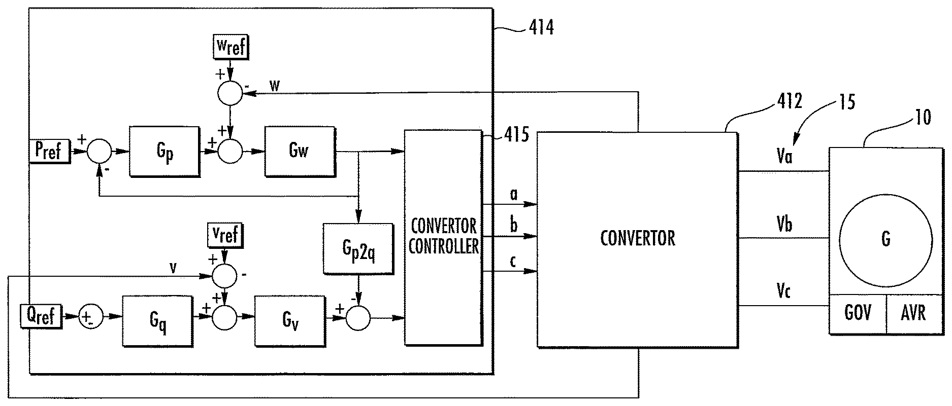
FIG. 5 is a block diagram illustrating a simplified SSG controller according to further embodiments.
DETAILED DESCRIPTION OF EMBODIMENTS
The present inventive subject matter will be described more fully hereinafter with reference to the accompanying figures, in which embodiments of the inventive subject matter are shown. This inventive subject matter may, however, be embodied in many alternate forms and should not be construed as limited to the embodiments set forth herein.
Accordingly, while the inventive subject matter is susceptible to various modifications and alternative forms, specific embodiments thereof are shown by way of example in the drawings and will herein be described in detail. It should be understood, however, that there is no intent to limit the inventive subject matter to the particular forms disclosed, but on the contrary, the inventive subject matter is to cover all modifications, equivalents, and alternatives falling within the spirit and scope of the inventive subject matter as defined by the claims. Like numbers refer to like elements throughout the description of the figures.
The terminology used herein is for the purpose of describing particular embodiments only and is not intended to be limiting of the inventive subject matter. As used herein, the singular forms "a", "an" and "the" are intended to include the plural forms as well, unless the context clearly indicates otherwise. It will be further understood that the terms "comprises", "comprising," "includes" and/or "including" when used in this specification, specify the presence of stated features, integers, steps, operations, elements, and/or components, but do not preclude the presence or addition of one or more other features, integers, steps, operations, elements, components, and/or groups thereof. Moreover, when an element is referred to as being "responsive" or "connected" to another element, it can be directly responsive or connected to the other element, or intervening elements may be present. In contrast, when an element is referred to as being "directly responsive" or "directly connected" to another element, there are no intervening elements present. As used herein the term "and/or" includes any and all combinations of one or more of the associated listed items and may be abbreviated as "/".
Unless otherwise defined, all terms (including technical and scientific terms) used herein have the same meaning as commonly understood by one of ordinary skill in the art to which this inventive subject matter belongs. It will be further understood that terms used herein should be interpreted as having a meaning that is consistent with their meaning in the context of this specification and the relevant art and will not be interpreted in an idealized or overly formal sense unless expressly so defined herein.
It will be understood that, although the terms first, second, etc. may be used herein to describe various elements, these elements should not be limited by these terms. These terms are only used to distinguish one element from another. For example, a first element could be termed a second element, and, similarly, a second element could be termed a first element without departing from the teachings of the disclosure. Although some of the diagrams include arrows on communication paths to show a primary direction of communication, it is to be understood that communication may occur in the opposite direction to the depicted arrows.
As discussed above, in some demanding applications, there are loads that require huge current magnitudes which would require multiple parallel generators to meet this demand to start these demanding loads and maintain the power and reactive components within the generator specifications under transient conditions. Once the load is started, the steady state load is relatively small, which does not require the operation of all these generators. The load steps can be predominately resistive which results in a change in active power (W) or the load steps can be reactive which results in a change in Volt-Ampere reactive (VAR) or a combination of both.
Accordingly, some embodiments of the inventive subject matter provide transient frequency and voltage stabilization systems and methods that may be used in island grid, utility grid, off-grid, grid-edge and other applications. In such applications, it may be possible to reduce, or possibly eliminate, the number of additional generators required to support the transient to start these demanding loads and maintain the power and reactive components within the generator specifications under transient and steady-state operation.
According to some embodiments, a Solid State Generator (SSG) offers a solution that supplies the load transient required by the load, allowing the generator to respond to a lower rate of load application that will maintain the load voltage and frequency within specifications. For the predominately resistive load step, the time shifting of the load step may be accomplished by using a form of energy store, such as capacitors or electrochemical storage. The compensation for the reactive component may not require any substantial energy store. In some embodiments, resistive and reactive components of a load step can be compensated by observing terminal characteristics of the SSG power terminals without requiring access to control circuitry of the generator. Thus, a transient stabilization system according to some embodiments may be configured as a "drop-in" device that may be connected to the grid without requiring communication with an engine/generator set and/or system controller.
On an off-grid or island grid application, a large load step from a motor or compressor start-up presents a formable challenge. The engine/generator sets are limited in resistive load step capability. For example, a diesel engine generator set can typically accept a maximum 50% load step while maintaining a less than 5% (e.g., +-2.5 Hz) frequency change. If the engine generator set is natural gas, the typical maximum load step to maintain the same frequency bounds is limited to only 10%. The reactive component of the load can also present a problem for the voltage regulator of the engine/generator set.
Exceeding the reactive component capability of the generator can cause the generator to trip-off line or disconnect from the load bus. Although we have discussed the problem as related to prime movers found in engine/generator sets, the problem may occur with a variety of types of generators, including those using turbines, micro turbines, linear/free piston engines, Wankel, fuel cells and the like.
During the motor start-up, large amounts of resistive and reactive components typically must be supplied to the load or the load bus will deviate outside acceptable range, which can cause the engine/generator sets to trip-off. FIG. 1 illustrates an example in which a 1.0 MW compressor is started. The compressor starting event begins at point A and ends at point B. With a soft starter, this starting event is 20 seconds in duration and the load has peak demands of 2.0 MW of power and 15 MVA of a reactive component, which far exceeds the capability of a typical engine/generator set.
FIG. 2 illustrates a typical governor for an engine/generator set. Step loading of the engine/generator set causes the load bus frequency and output voltage to droop because the generator slows down. The typical regulator is not able to increase the engine/generator set power fast enough in 20 seconds to prevent the bus voltage and frequency from dropping out of specification, where the response time is dependent on the time constant of the generator valve/gate control.
During the compressor startup period, the load current profile presents a large problem for an induction generator since its inductive impedance and the line inductance can be substantial. Because of the large magnitude of the transient reactive component in the load, the bus voltage will drop during the compressor startup event.
The amount of the voltage drop can be estimated using the following equations: .DELTA.U=R*.DELTA.Pc+X*.DELTA.Qc Eqn. (1) where, .DELTA.U=Bus voltage drop; R=System resistive impedance, including the generator resistance; X=System reactive impedance, including the generator reactance; .DELTA.Pe=transient power step; and .DELTA.Qe-transient reactive step.
FIG. 3 illustrates a typical control architecture for the engine/generator set automatic voltage regulator (AVR). During compressor start up, the AVR may not be able to adjust the voltage fast enough due to delays in the excitation system response.
To mitigate the startup currents, a soft start is typically used for large loads like a motor or compressor. As can be seen in FIG. 1, the power is gradually increased during the startup event allowing the generator to supply the load requirement. Unfortunately, this may not mitigate the issue with the reactive component of the load current profile. The presence of the large magnitude reactive component may cause the voltage regulator of the engine/generator set to alter the load bus voltage and frequency, which may cause the generator to trip off. To compensate for the reactive component of the load current, attempts to add compensating capacitor VAR compensation have been tried. The switching in/out of a large capacitor or maintained presence on the load bus may cause other stability issues with the engine/generator set regulators.
In some embodiments, an SSG can offer a solution that supplies load transients required by the load but isolates the engine/generator set from instantaneous load current demands and allows the engine/generator set to respond at a lower rate of load application. In response to a reactive load step, the SSG can supply a reactive component of the load current that can help isolate the engine/generator set from the issues with excessive reactive current. A change in frequency may be detected at the terminals of the SSG, and the SSG may responsively limit the rate of change of frequency by supplying power from the energy store to the load. As the engine/generator set assumes more of the load, the SSG can reduce the power supplied until the load is supported solely by the engine/generator set. Observing at the terminals of the SSG, the voltage change can be limited by supplying reactive power and decreasing the supplied reactive power as the bus voltage recovers.
FIG. 4 is a simplified block diagram illustrating an application of an SSG according to some embodiments. An engine/generator set 10 supplies power to a motor load 20 via an AC bus 15, which may be, for example, an island grid or other power distribution grid. An SSG 410 may include a 3-phase DC/AC power converter having 5 power terminals; positive, negative terminals coupled to an energy store 420 and three terminals coupled to respective phases of the AC bus 15 through respective inductors. Although the SSG 410 is shown connected to a battery, the energy store 420 can take any of a number of different forms, such as a lithium-ion battery bank, ultra capacitor bank, flywheel storage or the like. It should also be understood that a DC/DC converter can be used to interface the energy store 420 with the DC/AC power converter of the SSG 410. This can improve use of the energy store 420, since the terminal voltage of the energy store 420 can be different than the voltage of the DC bus used by the DC/AC power converter. The DC/DC converter is connected between the energy store 420 and the positive and negative terminals (DC bus) used by the DC/AC power converter bus that can deliver or receive power from the AC bus. The bidirectional DC/AC power converter of the SSG 410 is capable of using the DC bus and producing 3-phase AC voltages to support the load and it can transfer power from the AC bus 15 to the DC bus. Therefore, the 3-phase converter can look like a source or load depending on how the legs are controlled.
The SSG 410 connects to the AC bus 15 and can provide millisecond response times for power and reactive components of the load 20. This millisecond response time can mask the real load transients from the engine/generator set 10 so the voltage and frequency of the AC 15 remain in specification.
FIG. 5 illustrates a controller 414 that may be used to control the DC/AC converter 412 of the SSG 410. The controller 414 includes a converter controller 415 that generates control signals a, b, c for operating switching circuitry in the converter 412 to control output phases that are applied to an AC bus 15 driven by a motor/generator set 10 and having respective phase voltages Va, Vb, Vc. The controller 414 has an inner frequency loop that can detect a transient frequency and generate a frequency command signal P for the converter controller 415 responsive to which the DC/AC power converter 412 provides real power that is needed to compensate the system before the engine/generator set takes its slow response. An outer power control loop provides an input to the inner frequency loop and has a loop compensation of G.sub.P, which may have a transfer function of the form Kp1/(1+Tp1*s), where Kp1 and Tp1 are constants. A reference input P.sub.ref for the power control loop can, for example, be set to zero such that the controller transiently provides power when the frequency of the AC grid deviates from a reference frequency w.sub.ref. A power control loop structure along such lines is explained in U.S. Patent Application Publication No. 2014/0103727 to Taimela et al., the content of which is hereby incorporated by reference in its entirety.
According to some embodiments, the controller 414 further implements an inner voltage loop that detects a transient voltage and generates a voltage command signal Q for the controller 415 responsive to which the DC/AC power converter 412 provides a reactive component that is needed to compensate for the load demand before the engine/generator set is capable of responding. An outer reactive component control loop having a loop compensation G.sub.Q (which may have a transfer function of the form Kq1/(1+Tq1*s), where Kq1 and Tq1 are constants) provides an input to the inner voltage loop responsive to a reactive component reference signal Q.sub.ref. As the impedance network typically is not that complex in an island power system, once a reactive component demand step occurs as indicated by a deviation of an output voltage v of the converter 412 with respect to a reference voltage v.sub.ref, the SSG 410 can relatively quickly respond and compensate the reactive component to the bus, in order to regulate the bus voltage under the massive reactive component changes. This compensation method is usually sufficient under such massive reactive component step loadings. However, the effects of a bus voltage deviation due to a power load step, which may reduce the bus voltage, may be decoupled by adding a frequency dependent bus voltage change to the reactive component compensation so no error signal is generated to a power component only step load. This decoupling compensator is shown in FIG. 5, coupled between P Command and Q command.
For power control, the inner frequency loop detects bus frequency deviation and delivers/absorbs power through the fast compensator. The gain of the inner frequency loop may be set based on the frequency deviation requirement and the inertia of the system. In a relatively low inertia system, such as an island micro-grid, the active load step may create much more frequency deviation and, therefore, a smaller gain may be required. The gain G.sub.w of inner frequency loop may be estimated calculated using the following equation:
.DELTA..times..times..DELTA..times..times..times. ##EQU00001## where .DELTA.w is the target frequency deviation. The gain G.sub.w may have a transfer function of the form Kp2/(1+Tp2*s), wherein Kp2 and Tp2 are constants.
The outer power control loop provides steady state power flow control. In normal steady state, when there is no transient deviation in the bus, the SSG 410 delivers substantially no power into the bus, which may reduce semiconductor losses and extend the system lifetime. The power reference may be set negative during a charging state in order to let the generator slowly charge up the energy store 420. This may be done during periods in which transient load step conditions are not present. In some modes, recharge of the energy store 420 may be delayed for power peak-shaving. The duration of peak-shaving function may be based on the size and state of charge of the energy store 420.
Power and reactive components can impact the voltage stability. As the reactive component may be the major reason for voltage instability, a fast inner voltage loop may be implemented for reactive VAR compensation. The gain of the inner reactive component compensation G.sub.v may be estimated using the following equations:
.DELTA..times..times..DELTA..times..times..times. ##EQU00002##
where .DELTA.v is a target voltage deviation range, or
.apprxeq..times. ##EQU00003## where X is the reactance of the system. G.sub.v may have a transfer function of the form Kq2/(1+Tq2*s), where Kq2 and Tq2 are constants.
In some embodiments, in order to cancel out the voltage influence from the power component, a feed-forward path may be provided from the power error signal to the reactive component error signal. Thus, if only the power demand causes the voltage drop, injection of reactive component will be inhibited to reduce disturbance of the system. Gain of this crossover feedforward may be given by the following equation:
.times..times..times..apprxeq..times. ##EQU00004## where R is the resistance of the system. The crossover feedforward gain G.sub.p2q may have a transfer function of the form Kpq/(1+Tpq*s), wherein Kpq and Tpq are constants.
Since the reactive component may not provide any benefit in the steady state when there is no voltage deviation, the outer slow reactive component loop may be configured to substantially zero the reactive component in the long-term in order to reduce the loss and extend the lifetime of the SSG 410. If the transient conditions remain short, system cost may be reduced by sizing components based on overload ratings. For example, it may be possible to use 5MVA rated devices for a 10MVA transient requirement.
Understanding that the compensation for the reactive component does not require any substantial energy storage, the SSG 410 can provide some level of continuous reactive component in addition to the transient capability. In particular, the SSG 410 can be commanded to provide a fixed level of reactive component compensation resulting in reduced reactive component handled by the engine/generator set.
Reactive components from large motors tend to be primarily at the fundamental frequency. However, other types of reactive components can be harmonically related to the fundamental. These harmonically related reactive components are typically produced by loads that have non-sinusoidal current draw. The resultant current waveform can be simplified using a Fourier series analysis into a series of simple sinusoids that occur at integer multiples of the fundamental frequency. Therefore reactive components can be step applied as in a large motor starting event or a temporary or sustained reactive component due to non-sinusoidal current draw from a load. Accordingly, reactive compensation as described herein applies to fundamental and harmonic components. It will be further understood that reactive compensation techniques as described herein may be used to compensate for reactive loads other than motor loads, such as for capacitors that are switched in and out of the grid. For example, techniques along the lines described herein may be used to compensate for other reactance coupled to the grid and may be used in conjunction with other compensation techniques, such as reactive compensation capacitors connected to the grid.
The controller 414 may include digital hardware, such as a processor and field programmable gate array FPGA using a CompactRio or MicroZed.TM. control platform.
In the drawings and specification, there have been disclosed exemplary embodiments of the inventive subject matter. However, many variations and modifications can be made to these embodiments without substantially departing from the principles of the present inventive subject matter. Accordingly, although specific terms are used, they are used in a generic and descriptive sense only and not for purposes of limitation, the scope of the inventive subject matter being defined by the following claims.
* * * * *
References
D00000
D00001
D00002
D00003
M00001
M00002
M00003
M00004
XML
uspto.report is an independent third-party trademark research tool that is not affiliated, endorsed, or sponsored by the United States Patent and Trademark Office (USPTO) or any other governmental organization. The information provided by uspto.report is based on publicly available data at the time of writing and is intended for informational purposes only.
While we strive to provide accurate and up-to-date information, we do not guarantee the accuracy, completeness, reliability, or suitability of the information displayed on this site. The use of this site is at your own risk. Any reliance you place on such information is therefore strictly at your own risk.
All official trademark data, including owner information, should be verified by visiting the official USPTO website at www.uspto.gov. This site is not intended to replace professional legal advice and should not be used as a substitute for consulting with a legal professional who is knowledgeable about trademark law.