Barcoded indicators for quality management
Nemet , et al. Feb
U.S. patent number 10,572,785 [Application Number 16/124,107] was granted by the patent office on 2020-02-25 for barcoded indicators for quality management. This patent grant is currently assigned to Varcode Ltd.. The grantee listed for this patent is Varcode Ltd.. Invention is credited to Ephraim Brand, Yaron Nemet.


View All Diagrams
| United States Patent | 10,572,785 |
| Nemet , et al. | February 25, 2020 |
Barcoded indicators for quality management
Abstract
A barcoded indicator operative to provide a machine-readable indication of exceedance of at least one threshold by at least one product quality affecting parameter, the barcoded indicator including at least a first barcode and at least a second barcode, the at least a second barcode being in a second barcode unreadable state prior to exceedance of the at least one threshold and upon exceedance of the at least one threshold the at least a first barcode becoming unreadable and generally simultaneously the at least a second barcode becoming readable.
| Inventors: | Nemet; Yaron (Kedumim, IL), Brand; Ephraim (Givatayim, IL) | ||||||||||
|---|---|---|---|---|---|---|---|---|---|---|---|
| Applicant: |
|
||||||||||
| Assignee: | Varcode Ltd. (Rosh Ha'ayin,
IL) |
||||||||||
| Family ID: | 40639264 | ||||||||||
| Appl. No.: | 16/124,107 | ||||||||||
| Filed: | September 6, 2018 |
Prior Publication Data
| Document Identifier | Publication Date | |
|---|---|---|
| US 20190073574 A1 | Mar 7, 2019 | |
Related U.S. Patent Documents
| Application Number | Filing Date | Patent Number | Issue Date | ||
|---|---|---|---|---|---|
| 15587684 | May 5, 2017 | 10089566 | |||
| 15169851 | Jun 1, 2016 | 9646237 | |||
| 14528186 | Jul 5, 2016 | 9384435 | |||
| 14055422 | Apr 19, 2016 | 9317794 | |||
| 13321477 | Nov 12, 2013 | 8579193 | |||
| PCT/IL2010/000205 | Mar 10, 2010 | ||||
| 12469309 | Jan 10, 2012 | 8091776 | |||
| 61131644 | Jun 10, 2008 | ||||
| 61231799 | Aug 6, 2009 | ||||
Foreign Application Priority Data
| Nov 13, 2008 [WO] | PCTIL2008001494 | |||
| Nov 13, 2008 [WO] | PCTIL2008001495 | |||
| May 20, 2009 [WO] | PCTIL2009000503 | |||
| Dec 9, 2009 [WO] | PCTIL2009001167 | |||
| Current U.S. Class: | 1/1 |
| Current CPC Class: | G01K 3/10 (20130101); G01D 7/00 (20130101); G06K 7/1413 (20130101); G01K 11/14 (20130101); G06K 19/06028 (20130101); G06K 19/06046 (20130101); G01D 7/005 (20130101); G06Q 10/087 (20130101); G06K 7/1417 (20130101); G06K 19/06037 (20130101); G06K 19/0614 (20130101); G06Q 30/06 (20130101); G06K 19/0615 (20130101) |
| Current International Class: | G06K 19/06 (20060101); G01K 11/14 (20060101); G01D 7/00 (20060101); G06Q 10/08 (20120101); G01K 3/10 (20060101); G06Q 30/06 (20120101); G06K 7/14 (20060101) |
| Field of Search: | ;235/383,385,494 |
References Cited [Referenced By]
U.S. Patent Documents
| 4057029 | November 1977 | Seiter |
| 4059407 | November 1977 | Hochstrasser |
| RE31586 | May 1984 | Magnussen |
| 4674065 | June 1987 | Lange et al. |
| 5053339 | October 1991 | Patel |
| 5084143 | January 1992 | Smith |
| 5085802 | February 1992 | Jalinski |
| 5146405 | September 1992 | Church et al. |
| 5202677 | April 1993 | Parker et al. |
| 5254473 | October 1993 | Patel |
| 5369577 | November 1994 | Kadashevich et al. |
| 5451932 | September 1995 | Wunderlich et al. |
| 5485372 | January 1996 | Golding et al. |
| 5499597 | March 1996 | Kronberg |
| 5591952 | January 1997 | Krichever |
| 5600119 | February 1997 | Dvorkis |
| 5617488 | April 1997 | Hong et al. |
| 5634195 | May 1997 | Sawyer |
| 5659771 | August 1997 | Golding |
| 5752227 | May 1998 | Lyberg |
| 5805245 | September 1998 | Davis |
| 5822728 | October 1998 | Applebaum et al. |
| 5828991 | October 1998 | Skiena et al. |
| 5841285 | November 1998 | Bailey |
| 5882116 | March 1999 | Backus |
| 5895075 | April 1999 | Edwards |
| 5899973 | May 1999 | Bandara et al. |
| 5902982 | May 1999 | Lappe |
| 5907839 | May 1999 | Roth |
| 5936508 | August 1999 | Parker |
| 5956739 | September 1999 | Golding et al. |
| 6006221 | December 1999 | Liddy et al. |
| 6009400 | December 1999 | Blackman |
| 6036092 | March 2000 | Lappe |
| 6085206 | July 2000 | Domini et al. |
| 6098034 | August 2000 | Razin et al. |
| 6154722 | November 2000 | Bellegarda |
| 6173261 | January 2001 | Arai et al. |
| 6190610 | February 2001 | Goldsmith et al. |
| 6214623 | April 2001 | Simons et al. |
| 6272242 | August 2001 | Saitoh et al. |
| 6293470 | September 2001 | Asplund |
| 6314400 | November 2001 | Klakow |
| 6335922 | January 2002 | Tiedemann et al. |
| 6366759 | April 2002 | Burstein et al. |
| 6424983 | July 2002 | Schabes et al. |
| 6456972 | September 2002 | Gladstein et al. |
| 6479016 | November 2002 | Goldsmith |
| 6495368 | December 2002 | Wallach |
| 6544925 | April 2003 | Prusik et al. |
| 6685094 | February 2004 | Cameron |
| 6751584 | June 2004 | Bangalore |
| 6758397 | July 2004 | Catan |
| 6920420 | July 2005 | Lin |
| 6982640 | January 2006 | Lindsay |
| 7017806 | March 2006 | Peterson |
| 7020338 | March 2006 | Cumbee |
| 7030863 | April 2006 | Longe et al. |
| 7053777 | May 2006 | Allen |
| 7054293 | May 2006 | Tiedemann et al. |
| 7057495 | June 2006 | Debord |
| RE39226 | August 2006 | Lappe |
| 7092567 | August 2006 | Ma et al. |
| RE39266 | September 2006 | Lohray et al. |
| 7117144 | October 2006 | Goodman et al. |
| 7156597 | January 2007 | Goldsmith et al. |
| 7157048 | January 2007 | Goldsmith et al. |
| 7165019 | January 2007 | Lee et al. |
| 7166345 | January 2007 | Myers |
| 7184950 | February 2007 | Weise |
| 7224346 | May 2007 | Sheng |
| 7262792 | August 2007 | Shniberg |
| 7277088 | October 2007 | Robinson et al. |
| 7295965 | November 2007 | Haigh et al. |
| 7295968 | November 2007 | Bietrix et al. |
| 7296019 | November 2007 | Chandrasekar et al. |
| 7340388 | March 2008 | Soricut |
| 7386442 | June 2008 | Dehlinger et al. |
| 7457808 | November 2008 | Gaussier |
| 7475015 | January 2009 | Epstein et al. |
| 7558725 | July 2009 | Greenwald et al. |
| 7562811 | July 2009 | Nemet et al. |
| 7584093 | September 2009 | Potter et al. |
| 7587217 | September 2009 | Laakso et al. |
| 7590626 | September 2009 | Li et al. |
| 7702680 | April 2010 | Yih et al. |
| 7747427 | June 2010 | Lee et al. |
| 7813916 | October 2010 | Bean |
| 7917355 | March 2011 | Wu et al. |
| 8005664 | August 2011 | Hanumanthappa |
| 8091776 | January 2012 | Nemet |
| 8196821 | June 2012 | Nemet |
| 8242466 | August 2012 | Uber |
| 8271266 | September 2012 | Gallagher et al. |
| 8321786 | November 2012 | Lunati |
| 8341520 | December 2012 | Iakobashvili et al. |
| 8365070 | January 2013 | Song et al. |
| 8473278 | June 2013 | Futagi et al. |
| 8500014 | August 2013 | Nemet et al. |
| 8528808 | September 2013 | Nemet |
| 8540156 | September 2013 | Nemet |
| 8579193 | November 2013 | Nemet |
| 8626786 | January 2014 | Halcrow et al. |
| 8757503 | June 2014 | Conzelmann |
| 8807422 | August 2014 | Nemet |
| 8950664 | February 2015 | Nemet et al. |
| 8960534 | February 2015 | Nemet et al. |
| 8967467 | March 2015 | Nemet et al. |
| 9122963 | September 2015 | Nemet |
| 9135544 | September 2015 | Nemet et al. |
| 9317794 | April 2016 | Nemet |
| 9349086 | May 2016 | Nemet et al. |
| 9373100 | June 2016 | Nemet et al. |
| 9384435 | July 2016 | Nemet |
| 9396423 | July 2016 | Nemet et al. |
| 9400952 | July 2016 | Nemet |
| 9558439 | January 2017 | Nemet et al. |
| 9626610 | April 2017 | Nemet et al. |
| 9633296 | April 2017 | Nemet |
| 9646237 | May 2017 | Nemet et al. |
| 9646277 | May 2017 | Nemet et al. |
| 9710743 | July 2017 | Nemet |
| 9965712 | May 2018 | Nemet |
| 10037507 | July 2018 | Nemet et al. |
| 10049314 | August 2018 | Nemet et al. |
| 10089566 | October 2018 | Nemet |
| 2002/0012332 | January 2002 | Tiedemann et al. |
| 2002/0032564 | March 2002 | Eshani et al. |
| 2002/0056756 | May 2002 | Cameron et al. |
| 2002/0128821 | September 2002 | Ehsani |
| 2002/0169595 | November 2002 | Agichtein et al. |
| 2003/0136503 | July 2003 | Green et al. |
| 2003/0187632 | October 2003 | Menich |
| 2003/0204569 | October 2003 | Andrews et al. |
| 2003/0210249 | November 2003 | Simske |
| 2003/0227392 | December 2003 | Ebert |
| 2003/0233222 | December 2003 | Soricut et al. |
| 2004/0002849 | January 2004 | Zhou |
| 2004/0018641 | January 2004 | Goldsmith et al. |
| 2004/0030540 | February 2004 | Ovil et al. |
| 2004/0093567 | May 2004 | Schabes et al. |
| 2004/0138869 | July 2004 | Heinecke |
| 2004/0215514 | October 2004 | Devlin |
| 2004/0260543 | December 2004 | Horowitz |
| 2005/0043940 | February 2005 | Elder |
| 2005/0044495 | February 2005 | Lee et al. |
| 2005/0053900 | March 2005 | Kaufmann |
| 2005/0091030 | April 2005 | Jessee et al. |
| 2005/0091088 | April 2005 | Peterson |
| 2005/0108001 | May 2005 | Aarskog |
| 2005/0120002 | June 2005 | Behbehani |
| 2005/0139686 | June 2005 | Helmer et al. |
| 2005/0143971 | June 2005 | Burstein |
| 2005/0162274 | July 2005 | Shniberg et al. |
| 2005/0209844 | September 2005 | Wu et al. |
| 2005/0257146 | November 2005 | Ashcraft et al. |
| 2006/0003297 | January 2006 | Wiig et al. |
| 2006/0032427 | February 2006 | Ishii et al. |
| 2006/0048055 | March 2006 | Wu et al. |
| 2006/0057022 | March 2006 | Williams |
| 2006/0060657 | March 2006 | Choong et al. |
| 2006/0074655 | April 2006 | Bejar et al. |
| 2006/0081711 | April 2006 | Zhao et al. |
| 2006/0110714 | May 2006 | Symmes |
| 2006/0129381 | June 2006 | Wakita |
| 2006/0247914 | November 2006 | Brener et al. |
| 2006/0260958 | November 2006 | Brunner |
| 2007/0067177 | March 2007 | Martin |
| 2007/0094024 | April 2007 | Kristensson et al. |
| 2007/0106937 | May 2007 | Cucerzan et al. |
| 2007/0141544 | June 2007 | Nakane |
| 2007/0238084 | October 2007 | Maguire et al. |
| 2007/0241916 | October 2007 | Hedtke |
| 2007/0265831 | November 2007 | Dinur et al. |
| 2007/0271089 | November 2007 | Bates et al. |
| 2008/0059151 | March 2008 | Chen |
| 2008/0077859 | March 2008 | Schabes et al. |
| 2008/0154600 | June 2008 | Tian et al. |
| 2008/0167858 | July 2008 | Christie et al. |
| 2008/0173712 | July 2008 | Nemet |
| 2008/0189106 | August 2008 | Low et al. |
| 2008/0195940 | August 2008 | Gail et al. |
| 2008/0208567 | August 2008 | Brockett et al. |
| 2008/0208582 | August 2008 | Gallino |
| 2008/0249773 | October 2008 | Bejar et al. |
| 2008/0270897 | October 2008 | Jawerth et al. |
| 2009/0083028 | March 2009 | Davtchev et al. |
| 2009/0198671 | August 2009 | Zhang |
| 2009/0228467 | September 2009 | Asanuma |
| 2009/0230182 | September 2009 | Nemet et al. |
| 2009/0302102 | December 2009 | Nemet et al. |
| 2009/0319257 | December 2009 | Blume et al. |
| 2009/0320742 | December 2009 | Leute et al. |
| 2010/0020970 | January 2010 | Liu |
| 2010/0050074 | February 2010 | Nachmani et al. |
| 2010/0219235 | September 2010 | Nemet et al. |
| 2010/0269454 | October 2010 | Reddersen et al. |
| 2010/0275118 | October 2010 | Iakobashvili et al. |
| 2010/0286979 | November 2010 | Zangvil et al. |
| 2011/0006109 | January 2011 | Nemet |
| 2011/0006115 | January 2011 | Nemet |
| 2011/0093268 | April 2011 | Gorin et al. |
| 2011/0184720 | July 2011 | Zangvil |
| 2012/0104105 | May 2012 | Nemet |
| 2012/0104106 | May 2012 | Nemet |
| 2012/0145781 | June 2012 | Nemet |
| 2012/0305637 | December 2012 | Nemet |
| 2013/0024185 | January 2013 | Parikh |
| 2013/0074248 | March 2013 | Evans et al. |
| 2013/0138641 | May 2013 | Korolev et al. |
| 2013/0334301 | December 2013 | Nemet et al. |
| 2014/0001256 | January 2014 | Nemet et al. |
| 2014/0110486 | April 2014 | Nemet |
| 2014/0252096 | September 2014 | Nemet et al. |
| 2014/0353385 | December 2014 | Nemet |
| 2014/0360269 | December 2014 | Burghardt et al. |
| 2015/0047552 | February 2015 | Ortais |
| 2015/0053776 | February 2015 | Nemet et al. |
| 2015/0100105 | April 2015 | Kiani et al. |
| 2015/0122880 | May 2015 | Nemet et al. |
| 2015/0168223 | June 2015 | Hammond et al. |
| 2015/0193677 | July 2015 | Nemet et al. |
| 2015/0220877 | August 2015 | Nemet et al. |
| 2016/0042260 | February 2016 | Nemet |
| 2016/0071000 | March 2016 | Nemet et al. |
| 2016/0239781 | August 2016 | Nemet et al. |
| 2016/0275390 | September 2016 | Nemet et al. |
| 2016/0292554 | October 2016 | Nemet et al. |
| 2016/0371576 | December 2016 | Nemet et al. |
| 2016/0371577 | December 2016 | Nemet |
| 2016/0371635 | December 2016 | Nemet et al. |
| 2017/0177987 | June 2017 | Nemet et al. |
| 2017/0262782 | September 2017 | Nemet et al. |
| 2017/0270396 | September 2017 | Nemet |
| 2017/0277988 | September 2017 | Nemet et al. |
| 2017/0300791 | October 2017 | Nemet et al. |
| 2017/0344865 | November 2017 | Nemet et al. |
| 1720180 | Jan 2006 | CN | |||
| 1914621 | Feb 2007 | CN | |||
| 101365934 | Feb 2009 | CN | |||
| 204176727 | Feb 2015 | CN | |||
| 936753 | Aug 1999 | EP | |||
| S57-59293 | Apr 1982 | JP | |||
| 63094383 | Apr 1988 | JP | |||
| 63-118894 | May 1988 | JP | |||
| 3-53281 | Mar 1991 | JP | |||
| 5-6470 | Jan 1993 | JP | |||
| 5-19695 | Jan 1993 | JP | |||
| 5-67253 | Mar 1993 | JP | |||
| 9-504858 | Nov 1994 | JP | |||
| 2006-522933 | May 1997 | JP | |||
| 2001-502794 | Feb 2001 | JP | |||
| 2002-040012 | Feb 2002 | JP | |||
| 2002/504684 | Feb 2002 | JP | |||
| 2003-203210 | Jul 2003 | JP | |||
| 2003/525464 | Aug 2003 | JP | |||
| 2005-518320 | Jun 2005 | JP | |||
| 2006-18782 | Jan 2006 | JP | |||
| 2007121017 | May 2007 | JP | |||
| 2004-184920 | Jul 2007 | JP | |||
| 2008/089673 | Apr 2008 | JP | |||
| 1994/27144 | Nov 1994 | WO | |||
| 1994/27155 | Nov 1994 | WO | |||
| 1997/011535 | Mar 1997 | WO | |||
| 1998/14777 | Apr 1998 | WO | |||
| 1998/035514 | Dec 1998 | WO | |||
| 1999/042822 | Aug 1999 | WO | |||
| 2001/048680 | Jul 2001 | WO | |||
| 2001/064430 | Sep 2001 | WO | |||
| 2003/060626 | Jul 2003 | WO | |||
| 2004/038353 | May 2004 | WO | |||
| 2004/038535 | May 2004 | WO | |||
| 2004/092697 | Oct 2004 | WO | |||
| 2006-086053 | Aug 2006 | WO | |||
| 2007-049792 | May 2007 | WO | |||
| 2008/022140 | Feb 2008 | WO | |||
| 09/016631 | Feb 2009 | WO | |||
| 2007/129316 | Apr 2009 | WO | |||
| 2008/135962 | Apr 2009 | WO | |||
| 2009/063464 | May 2009 | WO | |||
| 2009/063465 | May 2009 | WO | |||
| 2009-144701 | Dec 2009 | WO | |||
| 2009/150641 | Dec 2009 | WO | |||
| 10/013228 | Feb 2010 | WO | |||
| 2010/134061 | Nov 2010 | WO | |||
| 2010/134062 | Nov 2010 | WO | |||
| 2016/185474 | Nov 2016 | WO | |||
| 2006/134795 | Dec 2016 | WO | |||
| 2017/006326 | Jan 2017 | WO | |||
Other References
|
US. Appl. No. 15/587,684, filed May 5, 2017 published as 2017/0300791, issued as 10,089,566. cited by applicant . U.S. Appl. No. 13/321,477, filed Jan. 17, 2012 published as 2012/0104106, issued as 8,579,193. cited by applicant . U.S. Appl. No. 14/055,422, filed Oct. 16, 2013 published as 2014/0252096, issued as 9,317,794. cited by applicant . U.S. Appl. No. 12/469,309, filed May 20, 2009 published as 2009/0302102, issued as 8,091,776. cited by applicant . U.S. Appl. No. 61/131,644, filed Jun. 10, 2008. cited by applicant . U.S. Appl. No. 61/231,799, filed Aug. 6, 2009. cited by applicant . U.S. Appl. No. 15/169,851, filed Jun. 1, 2016 published as 2016/0275390, issued as 9,646,237. cited by applicant . U.S. Appl. No. 14/528,186, filed Oct. 30, 2014 published as 2015/0053776, issued as 9,384,435. cited by applicant . An Office Action dated Nov. 4, 2013, which issued during the prosecution of U.S. Appl. No. 13/323,906. cited by applicant . An Office Action dated Oct. 11, 2016, which issued during the prosecution of U.S. Appl. No. 15/184,483. cited by applicant . A Notice of Allowance dated Nov. 18, 2014, which issued during the prosecution of U.S. Appl. No. 13/323,906. cited by applicant . A Notice of Allowance dated Apr. 23, 2014, which issued during the prosecution of U.S. Appl. No. 13/323,906. cited by applicant . An Office Action dated May 5, 2016, which issued during the prosecution of Canadian Patent Application No. 2,762,894. cited by applicant . A Notice of Allowance dated Apr. 25, 2014, which issued during the prosecution of U.S. Appl. No. 13/490,705. cited by applicant . A Notice of Allowance dated Nov. 7, 2014, which issued during the prosecution of U.S. Appl. No. 13/490,705. cited by applicant . An English translation of an Office Action dated Feb. 3, 2014 which issued during the.prosecution of Japanese Patent Application No. 2012-511407. cited by applicant . An English translation of an Office Action dated Aug. 26, 2014 which issued during the prosecution of Japanese Patent Application No. 2012-511407. cited by applicant . An Office Action dated Mar. 6, 2015, which issued during the prosecution of U.S. Appl. No. 14/055,422. cited by applicant . An English translation of an Office Action dated Jun. 25, 2013 which issued during the prosecution of Japanese Patent Application No. 2012-511406. cited by applicant . An English translation of an Office Action dated Jun. 5, 2018 which issued during the prosecution of Japanese Patent Application No. 2016-200656. cited by applicant . An Office Action dated Nov. 7, 2012, which issued during the prosecution of U.S. Appl. No. 12/743,209. cited by applicant . An English Translation of an Office Action dated Dec. 24, 2013 which issued during the prosecution of Chinese Patent Application No. 200980160387.4. cited by applicant . An Office Action dated Mar. 9, 2012, which issued during the prosecution of U.S. Appl. No. 12/743,209. cited by applicant . Notice of Allowance dated Apr. 14, 2014, which issued during the prosecution of U.S. Appl. No. 13/657,185. cited by applicant . An Office Action dated Jan. 16, 2013, which issued during the prosecution of U.S. Appl. No. 12/598,979. cited by applicant . An Office Action dated Dec. 19, 2012, which issued during the prosecution of U.S. Appl. No. 12/742,650. cited by applicant . An Office Action dated Mar. 20, 2012, which issued during the prosecution of U.S. Appl. No. 13/321,477. cited by applicant . An Office Action dated Aug. 14, 2015, which issued during the prosecution of U.S. Appl. No. 14/055,422. cited by applicant . An English Translation of an Office Action dated Feb. 26, 2013 which issued during the prosecution of Japanese Patent Application No. JP2009-508663. cited by applicant . An English Translation of an Office Action dated Jan. 15, 2013 which issued during the prosecution of Japanese Patent Application No. JP2010-507054. cited by applicant . An Extended European Search Report dated Feb. 11, 2013, which issued during the prosecution of European Patent Application No. 08848845. cited by applicant . An Extended European Search Report dated Feb. 18, 2013, which issued during the prosecution of European Application No. 09762166. cited by applicant . An Office Action dated Nov. 7, 2011, which issued during the prosecution of U.S. Appl. No. 12/598,979. cited by applicant . An International Preliminary Report on Patentability dated Nov. 22, 2011 which issued during the prosecution of Applicant's PCT/IL10/00205. cited by applicant . U.S. Appl. No. 60/746,646, filed May 7, 2006. cited by applicant . U.S. Appl. No. 60/804,072, filed Jun. 6, 2006. cited by applicant . An Office Action dated Oct. 28, 2013, which issued during the prosecution of U.S. Appl. No. 14/017,545. cited by applicant . An Office Action dated Jun. 20, 2008, which issued during the prosecution of U.S. Appl. No. 11/852,911. cited by applicant . An International Search Report and a Written Opinion both dated Jul. 17, 2008, which issued during the prosecution of Applicant's PCTIL2007000547. cited by applicant . An International Preliminary Report on Patentability dated Mar. 10, 2009, which issued during the prosecution of Applicant's PCTIL2007000547. cited by applicant . An International Search Report and a during the prosecution of Applicant's Written Opinion both dated Jan. 9, 2009, which issued PCT/IL2007/001411. cited by applicant . An International Preliminary Report on Patentability dated Nov. 10, 2009, which issued during the prosecution of Applicant's PCT/IL2007/001411. cited by applicant . A Notice of Allowance dated Feb. 15, 2012, which issued during the prosecution of U.S. Appl. No. 12/471,798. cited by applicant . European Search Report dated Aug. 18, 2011, which issued during the prosecution of European Patent Application No. 0 773 6287. cited by applicant . An Office Action dated Apr. 19, 2011, which issued during the prosecution of U.S. Appl. No. 12/469,309. cited by applicant . A Notice of Allowance dated Sep. 9, 2011, which issued during the prosecution of U.S. Appl. No. 12/469,309. cited by applicant . An Office Action dated May 3, 2011, which issued during the prosecution of U.S. Appl. No. 12/471,798. cited by applicant . An International Search Report and a Written Opinion both dated Aug. 31, 2009, which issued during the prosecution of Applicant's PCT/IL2009/000503. cited by applicant . An International Preliminary Report on Patentability dated Dec. 13, 2010, which issued during the prosecution of Applicant's PCT/IL2009/000503. cited by applicant . An International Search Report and a Written Opinion both dated Apr. 5, 2010, which issued during the prosecution of Applicant's PCT/IL2009/001167. cited by applicant . An International Preliminary Report on Patentability dated Nov. 22, 2011, which issued during the prosecution of Applicant's PCT/IL2009/001167. cited by applicant . A Notice of Allowance dated Apr. 2, 2013, which issued during the prosecution of U.S. Appl. No. 12/743,209. cited by applicant . An English Translation of an Office Action dated May 22, 2015 which issued during the prosecution of Chinese Patent Application No. 200980160387.4. cited by applicant . An Office Action dated Sep. 10, 2013, which issued during the prosecution of U.S. Appl. No. 13/657,185. cited by applicant . An English translation of an Office Action dated Sep. 10, 2013 which issued during the prosecution of Japanese Patent Application No. 2011-513110. cited by applicant . An English translation of an Office Action dated Aug. 27, 2013 which issued during the prosecution of Japanese Patent Application No. 2010-507054. cited by applicant . An Examiner Interview Summary Report dated Nov. 7, 2008, which issued during the prosecution of U.S. Appl. No. 11/852,911. cited by applicant . A Notice of Allowance dated Feb. 25, 2009, which issued during the prosecution of U.S. Appl. No. 11/852,911. cited by applicant . An Office Action dated Mar. 15, 2013, which issued during the prosecution of U.S. Appl. No. 13/321,467. cited by applicant . A Notice of Allowance dated Jul. 11, 2013, which issued during the prosecution of U.S. Appl. No. 13/321,477. cited by applicant . An Office Action dated Jul. 12, 2013, which issued during the prosecution of European Patent Application No. 07736287.9. cited by applicant . A Notice of Allowance dated May 16, 2013, which issued during the prosecution of U.S. Appl. No. 12/742,650. cited by applicant . An Office Action dated Sep. 18, 2014, which issued during the prosecution of U.S. Appl. No. 14/143,827. cited by applicant . A Notice of Allowance dated Oct. 15, 2014, which issued during the prosecution of U.S. Appl. No. 14/017,545. cited by applicant . A Notice of Allowance dated Apr. 17, 2009, which issued during the prosecution of U.S. Appl. No. 11/852,911. cited by applicant . An Office Action dated Sep. 9, 2011, which issued during the prosecution of U.S. Appl. No. 12/471,798. cited by applicant . An Office Action dated Oct. 12, 2012, which issued during the prosecution of U.S. Appl. No. 12/669,175. cited by applicant . An Office Action dated Aug. 5, 2013, which issued during the prosecution of U.S. Appl. No. 12/669,175. cited by applicant . An Office Action dated Feb. 5, 2013, which issued during the prosecution of U.S. Appl. No. 12/669,175. cited by applicant . An Office Action dated Mar. 7, 2014, which issued during the prosecution of U.S. Appl. No. 12/669,175. cited by applicant . A Notice of Allowance dated Aug. 4, 2014, which issued during the prosecution of U.S. Appl. No. 12/669,175. cited by applicant . An English Translation of an Office Action dated Apr. 22, 2014 which issued during the prosecution of Israeli Patent Application No. 205687. cited by applicant . An English Translation of an Office Action dated Oct. 27, 2014 which issued during the prosecution of Israeli Patent Application No. 209901. cited by applicant . A Notice of Allowance dated Dec. 14, 2016, which issued during the prosecution of U.S. Appl. No. 15/189,127. cited by applicant . An Office Action dated Jul. 1, 2014, which issued during the prosecution of U.S. Appl. No. 13/576,330. cited by applicant . An International Search Report and a Written Opinion both dated Oct. 3, 2016, which issued during the prosecution of Applicant's PCT/IL2016/050526. cited by applicant . An English Translation of an Office Action dated Jun. 13, 2014 which issued during the prosecution of Chinese Patent Application No. 200880101405.7. cited by applicant . An Office Action dated Nov. 23, 2016, which issued during the prosecution of U.S. Appl. No. 15/063,804. cited by applicant . Letter submitted on Jul. 17, 2009 in U.S. Appl. No. 11/852,911. cited by applicant . A Notice of Allowance dated Oct. 26, 2016, which issued during the prosecution of U.S. Appl. No. 15/189,127. cited by applicant . An Office Action dated May 9, 2013, which issued during the prosecution of U.S. Appl. No. 12/937,618. cited by applicant . An English Translation of an Office Action dated Jan. 25, 2013 which issued during the prosecution of Chinese Patent Application No. 200880101405.7. cited by applicant . Notice of Allowance dated Jan. 5, 2017, which issued during the prosecution of U.S. Appl. No. 15/183,465. cited by applicant . An English Translation of an Office Action dated Apr. 28, 2012 which issued during the prosecution of Chinese Patent Application No. 200880101405.7. cited by applicant . Notice of Allowance dated May 13, 2015, which issued during the prosecution of U.S. Appl. No. 14/461,778. cited by applicant . A Notice of Allowance dated Jun. 27, 2014, which issued during the prosecution of U.S. Appl. No. 14/017,545. cited by applicant . A Supplementary European Search Report dated Jul. 5, 2012, which issued during the prosecution of European Patent Application No. 08789727. cited by applicant . An English Translation of an Office Action dated Jun. 23, 2011 which issued during the prosecution of Chinese Patent Application No. 200880101405.7. cited by applicant . An International Search Report and a Written Opinion both dated May 25, 2011, which issued during the prosecution of Applicant's PCT/IL2011/00088. cited by applicant . An International Search Report dated May 11, 2009, which issued during the prosecution of Applicant's PCT/IL2009/00130. cited by applicant . An International Search Report dated Jun. 26, 2009, which issued during the prosecution of Applicant's PCT/IL2009/00317. cited by applicant . An International Preliminary Examination Report dated Oct. 19, 2010, which issued during the prosecution of Applicant's PCT/IL2009/00317. cited by applicant . Bick, E., "A Constraint Grammar Based Spellchecker for Danish with a Special Focus on Dyslexics" SKY Journal of Linguistics, vol. 19:2006 (ISSN 1796-279X), pp. 387-396 (retrieved Jan. 12, 2009 from the internet). <URL http://www.ling.helsinki.fi/sky/julkaisut/SKY2006_1/1.6.1%20BICK.pdf>. cited by applicant . An International Search Report and Written Opinion both dated Feb. 3, 2009 which issued during the prosecution of Applicant's PCT/IL08/01051. cited by applicant . An Office Action dated Jan. 10, 2014, which issued during the prosecution of European Patent Application No. 08848845. cited by applicant . An Office Action dated Jun. 5, 2014, which issued during the prosecution of U.S. Appl. No. 14/017,545. cited by applicant . A Notice of Allowance dated Apr. 26, 2013, which issued during the prosecution of U.S. Appl. No. 12/598,979. cited by applicant . A Supplementary European Search Report dated Apr. 13, 2011, which issued during the prosecution of European Patent Application No. 07827384. cited by applicant . An English Translation of an Office Action dated Feb. 7, 2012 which issued during the.prosecution of Japanese Patent Application No. JP2009-508663. cited by applicant . A Supplementary European Search Report dated Aug. 23, 2012, which issued during the prosecution of European Patent Application No. 08849330.9. cited by applicant . An International Preliminary Report on Patentability dated May 18, 2010, which issued during the prosecution of Applicant's PCT/IL2008/001495. cited by applicant . An International Preliminary Report on Patentability dated May 18, 2010, which issued during the prosecution of Applicant's PCT/IL2008/001494. cited by applicant . An International Search Report and a Written Opinion both dated Jun. 3, 2009, which issued during the prosecution of Applicant's PCT/IL2008/001494. cited by applicant . An International Search Report and a Written Opinion both dated Jun. 8, 2010, which issued during the prosecution of Applicant's PCT/IL2010/000205. cited by applicant . An International Search Report and a Written Opinion both dated Mar. 9, 2009, which issued during the prosecution of Applicant's PCT/IL2008/001495. cited by applicant . An Office Action dated Apr. 25, 2012, which issued during the prosecution of U.S. Appl. No. 12/598,979. cited by applicant . An English Translation of an Office Action dated Oct. 25, 2012 which issued during the prosecution of Israeli Patent Application No. 201958. cited by applicant . An Office Action dated Jan. 21, 2015, which issued during the prosecution of U.S. Appl. No. 14/461,778. cited by applicant . An Office Action dated Feb. 11, 2015, which issued during the prosecution of U.S. Appl. No. 13/958,893. cited by applicant . An English Translation of an Office Action dated Feb. 18, 2014 which issued during the prosecution of Japanese Patent Application No. JP2009-508663. cited by applicant . U.S. Appl. No. 60/963,956, filed Aug. 6, 2007. cited by applicant . U.S. Appl. No. 60/959,120, filed Jul. 10, 2007. cited by applicant . An Office Action dated Sep. 25, 2014, which issued during the prosecution of U.S. Appl. No. 14/461,778. cited by applicant . An English Translation of an Office Action dated Nov. 4, 2014 which issued during the prosecution of Chinese Patent Application No. 201080030956.6. cited by applicant . An English Translation of an Office Action dated Apr. 19, 2015 which issued during the prosecution of Israeli Patent Application No. 216396. cited by applicant . An English Translation of an Office Action dated Nov. 15, 2014 which issued during the prosecution of Chinese Patent Application No. 200980160387.4. cited by applicant . An English Translation of an Office Action dated Jan. 6, 2014 which issued during the prosecution of Chinese Patent Application No. 201080030956.6. cited by applicant . An English translation of an Office Action dated Jul. 28, 2015 which issued during the prosecution of Japanese Patent Application No. 2014-125707. cited by applicant . Notice of Allowance dated May 29, 2015, which issued during the prosecution of U.S. Appl. No. 13/958,893. cited by applicant . An Office Action dated Jul. 28, 2015, which issued during the prosecution of U.S. Appl. No. 14/595,412. cited by applicant . U.S. Appl. No. 62/163,193, filed May 18, 2015. cited by applicant . U.S. Appl. No. 62/189,367, filed Jul. 7, 2015. cited by applicant . An English translation of an Office Action dated Aug. 27, 2015 which issued during the prosecution of Japanese Patent Application No. 2014-218223. cited by applicant . An English Translation of an Office Action dated Dec. 31, 2015 which issued during the prosecution of Israeli Patent Application No. 209901. cited by applicant . An English Translation of an Office Action dated Apr. 20, 2015 which issued during the prosecution of Israeli Patent Application No. 216397. cited by applicant . A Supplementary European Search Report dated Sep. 23, 2015, which issued during the prosecution of European Patent Application No. 10777451.5. cited by applicant . European Search Report dated Sep. 16, 2015, which issued during the prosecution of European Patent Application No. 09844849. cited by applicant . A Notice of Allowance dated Dec. 8, 2015, which issued during the prosecution of U.S. Appl. No. 14/055,422. cited by applicant . A Notice of Allowance dated Jan. 18, 2017, which issued during the prosecution of U.S. Appl. No. 15/137,316. cited by applicant . An Office Action dated Nov. 19, 2013, which issued during the prosecution of European Application No. 07827384.4. cited by applicant . A Notice of Allowance dated Mar. 23, 2016, which issued during the prosecution of U.S. Appl. No. 14/823,758. cited by applicant . A Notice of Allowance dated Feb. 4, 2016, which issued during the prosecution of U.S. Appl. No. 14/595,395. cited by applicant . An Office Action dated Dec. 4, 2015, which issued during the prosecution of U.S. Appl. No. 14/823,758. cited by applicant . A Notice of Allowance dated Feb. 2, 2016, which issued during the prosecution of U.S. Appl. No. 14/595,412. cited by applicant . A Notice of Allowance dated Mar. 16, 2016, which issued during the prosecution of U.S. Appl. No. 14/595,954. cited by applicant . A Notice of Allowance dated Mar. 3, 2016, which issued during the prosecution of U.S. Appl. No. 14/528,186. cited by applicant . A Notice of Allowance dated Oct. 11, 2016, which issued during the prosecution of U.S. Appl. No. 14/823,702. cited by applicant . An English translation of an Office Action dated Jun. 14, 2016 which issued during the prosecution of Japanese Patent Application No. 2014-125707. cited by applicant . An English translation of an Office Action dated Mar. 15, 2016, which issued during the prosecution of Japanese Patent Application No. 2014-218223. cited by applicant . An Office Action dated Jan. 29, 2016, which issued during the prosecution of U.S. Appl. No. 14/595,954. cited by applicant . An Office Action dated Sep. 27, 2016, which issued during the prosecution of U.S. Appl. No. 15/189,127. cited by applicant . An Office Action dated Jun. 27, 2016, which issued during the prosecution of U.S. Appl. No. 14/823,702. cited by applicant . An Office Action dated Jan. 29, 2016, which issued during the prosecution of U.S. Appl. No. 14/528,186. cited by applicant . An Office Action dated Jan. 26, 2016, which issued during the prosecution of Canadian Patent Application No. 2762891. cited by applicant . An International Search Report and a Written Opinion both dated Dec. 12, 2016, which issued during the prosecution of Applicant's PCT/IL2016/050727. cited by applicant . An Office Action dated Jan. 24, 2017, which issued during the prosecution of Canadian Patent Application No. 2,762,894. cited by applicant . An Office Action dated Dec. 13, 2016, which issued during the prosecution of U.S. Appl. No. 15/169,851. cited by applicant . An Office Action dated Jun. 29, 2017, which issued during the prosecution of U.S. Appl. No. 15/398,951. cited by applicant . An English translation of an Office Action dated Nov. 2, 2016, which issued during the prosecution of Japanese Patent Application No. 2014-125707. cited by applicant . Notice of Allowance dated Mar. 23, 2017, which issued during the prosecution of U.S. Appl. No. 15/169,851. cited by applicant . Notice of Allowance dated Mar. 20, 2017, which issued during the prosecution of U.S. Appl. No. 15/063,804. cited by applicant . Notice of Allowance dated Aug. 3, 2017, which issued during the prosecution of U.S. Appl. No. 15/398,951. cited by applicant . An Office Action dated Jun. 28, 2017, which issued during the prosecution of U.S. Appl. No. 15/495,022. cited by applicant . An Office Action dated Jul. 27, 2017, which issued during the prosecution of U.S. Appl. No. 15/184,483. cited by applicant . An Office Action dated Jul. 26, 2017, which issued during the prosecution of U.S. Appl. No. 15/486,906. cited by applicant . An Office Action together with the English translation dated Sep. 5, 2017, which issued during the prosecution of Japanese Patent Application No. 2016-200656. cited by applicant . An Office Action dated Sep. 26, 2017, which issued during the prosecution of U.S. Appl. No. 15/488,943. cited by applicant . Notice of Allowance dated Jan. 4, 2018, which issued during the prosecution of U.S. Appl. No. 15/495,022. cited by applicant . An Office Action dated Jan. 2, 2018, which issued during the prosecution of U.S. Appl. No. 15/184,483. cited by applicant . An Office Action dated Dec. 19, 2017, which issued during the prosecution of U.S. Appl. No. 15/632,916. cited by applicant . An Office Action dated Nov. 27, 2017, which issued during the prosecution of U.S. Appl. No. 15/587,684. cited by applicant . An International Preliminary Report on Patentability dated Jan. 9, 2018, which issued during the prosecution of Applicant's PCT/IL2016/050727. cited by applicant . An Office Action dated Mar. 22, 2018, which issued during the prosecution of U.S. Appl. No. 15/587,684. cited by applicant . An Office Action dated Jul. 12, 2018, which issued during the prosecution of U.S. Appl. No. 15/944,122. cited by applicant . An Office Action dated Sep. 12, 2018, which issued during the prosecution of U.S. Appl. No. 15/978,759. cited by applicant . Notice of Allowance dated Feb. 16, 2018, which issued during the prosecution of U.S. Appl. No. 15/486,906. cited by applicant . An English translation of an Office Action dated Dec. 12, 2017, which issued during the prosecution of Japanese Patent Application No. 2014-125707. cited by applicant . An Office Action dated Jul. 12, 2018, which issued during the prosecution of U.S. Appl. No. 15/800,660. cited by applicant . Notice of Allowance dated Apr. 12, 2018, which issued during the prosecution of U.S. Appl. No. 15/632,916. cited by applicant . Notice of Allowance dated Aug. 24, 2018, which issued during the prosecution of U.S. Appl. No. 15/184,843. cited by applicant . Notice of Allowance dated Oct. 3, 2018, which issued during the prosecution of U.S. Appl. No. 15/184,483. cited by applicant . Notice of Allowance dated Mar. 30, 2018, which issued during the prosecution of U.S. Appl. No. 15/488,943. cited by applicant . Notice of Allowance dated Feb. 22, 2018, which issued during the prosecution of U.S. Appl. No. 15/486,906. cited by applicant . Notice of Allowance dated May 30, 2018, which issued during the prosecution of U.S. Appl. No. 15/587,684. cited by applicant . European Search Report dated Apr. 11, 2018 which issued during the prosecution of Applicant's European App No. 08848845.7. cited by applicant . Notice of Allowance dated Jan. 9, 2019, which issued during the prosecution of U.S. Appl. No. 15/978,759. cited by applicant . An Office Action dated Feb. 26, 2019, which issued during the prosecution of U.S. Appl. No. 16/026,585. cited by applicant . European Search Report dated Feb. 11, 2019 which issued during the prosecution of Applicant's European App No. 16820959.1. cited by applicant . European Search Report dated Dec. 20, 2018, which issued during the prosecution of Applicant's European App No. 16796019.4. cited by applicant. |
Primary Examiner: Hess; Daniel A
Attorney, Agent or Firm: Fish & Richardson P.C.
Parent Case Text
REFERENCE TO RELATED APPLICATIONS
This application is a continuation of U.S. patent application Ser. No. 14/055,422, filed Oct. 16, 2013 and entitled "Barcoded Indicators For Quality Management," which is a continuation of U.S. patent application Ser. No. 13/321,477, now U.S. Pat. No. 8,579,193, filed Jan. 17, 2012 and entitled "Barcoded Indicators For Quality Management." U.S. patent application Ser. No. 13/321,477 is a National Phase application of PCT/IL2010/000205, filed Mar. 10, 2010 and claims priority of PCT/IL2009/000503, filed May 20, 2009, U.S. patent application Ser. No. 12/469,309, now U.S. Pat. No. 8,091,776, filed May 20, 2009, U.S. Provisional Patent Application No. 61/231,799, filed Aug. 6, 2009 and PCT/IL2009/001167, filed Dec. 9, 2009, the disclosures of which are all hereby incorporated by reference.
Reference is made to U.S. Pat. No. 7,562,811, filed Sep. 10, 2007 and entitled "System And Method For Improved Quality Management In A Product Logistic Chain", to PCT Patent Application No. PCT/IL07/000547, filed May 6, 2007 and entitled "A System And Method For improved Quality Management In A Product Logistic Chain", to PCT Patent Application No. PCT/IL07/01411, filed Nov. 14, 2007 and entitled "A System And Method For Quality Management Utilizing Barcode Indicators", to PCT Patent Application No. PCT/IL2008/001495, filed Nov. 13, 2008 and entitled "A System And Method For Quality Management Utilizing Barcode Indicators", to PCT Patent Application No. PCT/IL2008/001494, filed Nov. 13, 2008 and entitled "A System And Method For Quality Management Utilizing Barcode Indicators", to PCT Patent Application No. PCT/IL2009/000503, filed May 20, 2009 and entitled "A System And Method For Quality Management Utilizing Barcode Indicators" to U.S. patent application Ser. No. 12/469,309, filed May 20, 2009 and entitled "A System And Method For Quality Management Utilizing Barcode Indicators", to U.S. Provisional Patent Application Ser. No. 61/231,799, filed Aug. 6, 2009 and entitled "Barcoded Indicators For Quality Management" and to PCT Patent Application No. PCT/IL2009/001167, filed Dec. 9, 2009 and entitled "Barcode Indicators for Quality Management", the disclosures of which are hereby incorporated by reference.
Priority is hereby claimed under 37 CFR 1.78(a) (1) and (2)(i) from PCT Patent Application No. PCT/IL2009/000503, filed May 20, 2009 and entitled "A System And Method For Quality Management Utilizing Barcode Indicators", from U.S. patent application Ser. No. 12/469,309, filed May 20, 2009 and entitled "A System And Method For Quality Management Utilizing Barcode Indicators" and from PCT Patent Application No. PCT/IL2009/001167, filed Dec. 9, 2009 and entitled "Barcode Indicators for Quality Management", and under 37 CFR 1.78(a) (4) and (5)(i) from U.S. Provisional Patent Application Ser. No. 61/231,799, filed Aug. 6, 2009 and entitled "Barcoded Indicators For Quality Management".
Claims
The invention claimed is:
1. A quality management system for products comprising: a multiplicity of barcoded indicators each operative to provide a machine-readable indication of exceedance of at least one threshold by one or more product quality affecting parameters, each of said barcoded indicators comprising: at least a first barcode including at least a first set of initially uncolored, colorable areas including at least one initially uncolored colorable area, positioned at locations between bars of said first barcode when said first barcode is in a first barcode readable state prior to exceedance of said at least one threshold; at least a second barcode including at least a second set of initially uncolored, colorable areas including at least one initially uncolored colorable area, positioned at locations of bars of said second barcode which appear only when said second barcode is in a second barcode readable state following exceedance of said at least one threshold, a coloring agent located at a first location on said indicator; and a coloring agent pathway operative to allow said coloring agent to move from said first location to said first and second sets of colorable areas for coloring thereof, said at least a second barcode being in a second barcode unreadable state prior to exceedance of said at least one threshold wherein as the result of said at least a second set being uncolored, more than a single narrow barcode bar is missing from said at least a second barcode, and upon exceedance of said at least one threshold said at least a first barcode becoming unreadable as the result of coloring of at least a portion of at least one colorable area forming part of said at least a first set of colorable areas and generally simultaneously said at least a second barcode becoming readable as the result of coloring of said at least a second set of colorable areas; a barcode indicator reader operative to read said barcoded indicators and to provide output indications; and a product type responsive indication interpreter operative to receive said output indications and to provide human sensible, product quality status outputs.
2. A quality management system for products according to claim 1 and wherein said coloring agent pathway is operative to allow said coloring agent to move by diffusing from said first location to said first and said second sets of colorable areas.
3. A quality management system for products according to claim 1 and wherein each of said first set of colorable areas and said second set of colorable areas includes at least two colorable areas.
4. A quality management system for products according to claim 1 and wherein said first set of colorable areas continues to be colored following exceedance of said at least one threshold.
5. A quality management system for products according to claim 1 and wherein said at least one threshold includes at least one time threshold.
6. A quality management system for products according to claim 1 and wherein said at least one threshold includes at least one time and temperature threshold.
7. A quality management system for products according to claim 1 and wherein said quality indicator is operative to provide indications of exceedance of several different thresholds.
8. A quality management system for products according to claim 1 and wherein at least one colorable area forming part of one of said first set of colorable areas and said second set of colorable areas has a width of a single narrow barcode bar.
9. A quality management system for products according to claim 1 and wherein colorable areas forming part of at least one of said first set of colorable areas and said second set of colorable areas become colored sequentially.
10. A quality management system for products according to claim 1 and wherein at least one of said first set of colorable areas and said second set of colorable areas includes at least two colorable areas.
11. A quality management system for products according to claim 1, and wherein each of said barcoded indicators is operative to provide a machine-readable indication of exceedance of at least one additional threshold by at least one product quality affecting parameter, each of said barcoded indicators further comprising: at least a third barcode including at least a third set of initially uncolored, colorable areas including at least one initially uncolored colorable area, positioned at locations of bars of said third barcode which appear only when said third barcode is in a third barcode readable state following exceedance of said at least one additional threshold, said at least a third barcode being in a third barcode unreadable state prior to exceedance of said at least one additional threshold wherein as the result of said third set of colorable areas being uncolored, more than a single narrow barcode bar is missing from said at least a third barcode, said at least a second barcode including at least a fourth set of initially uncolored, colorable areas including at least one initially uncolored colorable area, positioned at locations between bars of said at least a second barcode when said at least a second barcode is in said second barcode readable state prior to exceedance of said at least one additional threshold, and upon exceedance of said at least one additional threshold said at least a second barcode becoming unreadable as the result of coloring of at least a portion of at least one colorable area forming part of said at least a fourth set of colorable areas and generally simultaneously said at least a third barcode becoming readable as the result of coloring of said at least a third set of colorable areas.
Description
FIELD OF THE INVENTION
The present invention relates to quality management and to indicators useful in quality management.
BACKGROUND OF THE INVENTION
The following U.S. Patents relate generally to the subject matter of the present application: U.S. Pat. Nos. 6,758,397, 6,009,400, 6,685,094, 7,157,048, 7,156,597 and RE 39,226.
SUMMARY OF THE INVENTION
The present invention seeks to provide improved indicators useful in quality management systems and methodologies.
There is thus provided in accordance with a preferred embodiment of the present invention a barcoded indicator operative to provide a machine-readable indication of exceedance of at least one threshold by at least one product quality affecting parameter, the barcoded indicator including at least a first barcode including at least a first set of initially uncolored, colorable areas including at least one initially uncolored colorable area, positioned at locations between bars of the first barcode when the first barcode is in a first barcode readable state prior to exceedance of the at least one threshold, and at least a second barcode including at least a second set of initially uncolored, colorable areas including at least one initially uncolored colorable area, positioned at locations of bars of the second barcode which appear only when the second barcode is in a second barcode readable state following exceedance of the at least one threshold, the at least a second barcode being in a second barcode unreadable state prior to exceedance of the at least one threshold wherein as the result of the at least a second set being uncolored, more than a single narrow barcode bar is missing from the at least a second barcode, and upon exceedance of the at least one threshold the at least a first barcode becoming unreadable as the result of coloring of at least a portion of at least one colorable area forming part of the at least a first set of colorable areas and generally simultaneously the at least a second barcode becoming readable as the result of coloring of the at least a second set of colorable areas.
Preferably, the barcode indicator includes a coloring agent located at a first location on the indicator and a coloring agent pathway operative to allow the coloring agent to move, at a rate which is at least partially a function of time, from the first location to the first and second sets of colorable areas for coloring thereof.
Additionally, the coloring agent pathway is operative to allow the coloring agent to move by diffusing from the first location to the first and the second sets of colorable areas.
Preferably, the first set of colorable areas continues to be colored following exceedance of the at least one threshold.
Preferably, the at least one threshold includes at least one time threshold.
Preferably, the at least one threshold includes at least one time and temperature threshold.
Preferably, the quality indicator is operative to provide indications of exceedance of several different thresholds.
Preferably, at least one colorable area forming part of one of the first set of colorable areas and the second set of colorable areas has a width of a single narrow barcode bar.
Preferably, colorable areas forming part of at least one of the first set of colorable areas and the second set of colorable areas become colored sequentially.
Preferably, at least one of the first set of colorable areas and the second set of colorable areas includes at least two colorable areas. Additionally, each of the first set of colorable areas and the second set of colorable areas includes at least two colorable areas.
Preferably, the barcoded indicator further including at least a third barcode including at least a third set of initially uncolored, colorable areas including at least one initially uncolored colorable area, positioned at locations of bars of the third barcode which appear only when the third barcode is in a third barcode readable state following exceedance of the at least one additional threshold, the at least a third barcode being in a third barcode unreadable state prior to exceedance of the at least one additional threshold wherein as the result of the third set of colorable areas being uncolored, more than a single narrow barcode bar is missing from the at least a third barcode, the at least a second barcode including at least a fourth set of initially uncolored, colorable areas including at least one initially uncolored colorable area, positioned at locations between bars of the at least a second barcode when the at least a second barcode is in the second barcode readable state prior to exceedance of the at least one additional threshold, and upon exceedance of the at least one additional threshold the at least a second barcode becoming, unreadable as the result of coloring of at least a portion of at least one colorable area forming part of the at least a fourth set of colorable areas and generally simultaneously the at least a third barcode becoming readable as the result of coloring of the at least a third set of colorable areas.
BRIEF DESCRIPTION OF THE DRAWINGS
The present invention will be understood and appreciated more fully from the following detailed description, taken in conjunction with the drawings in which:
FIGS. 1A-1K together are a simplified illustration of the structure and operation of an example of a quality indicator constructed and operative in accordance with a preferred embodiment of the present invention for indicating elapsed time in temperature history;
FIGS. 2A-2K together are a simplified illustration of the structure and operation of another example of a quality indicator constructed and operative in accordance with another preferred embodiment of the present invention for indicating elapsed time in temperature history;
FIGS. 3A-3K together are a simplified illustration of the structure and operation of an example of the quality indicator constructed and operative in accordance with a preferred embodiment of the present invention for indicating elapsed time in temperature history; and
FIGS. 4A-4K together are a simplified illustration of the structure and operation of another example of the quality indicator constructed and operative in accordance with another preferred embodiment of the present invention for indicating elapsed time in temperature history.
DETAILED DESCRIPTION OF PREFERRED EMBODIMENTS
The present invention provides changeable barcode indicators operative to provide a machine-readable, preferably barcode-reader-readable, indication of exceedance of at least one threshold by at least one product quality affecting parameter.
Barcode readers operative to read the barcode indicators and to provide output indications, and product type responsive indication interpreters operative to receive the output indications and to provide human sensible, product quality status outputs are described in U.S. Pat. No. 7,562,811 and in the publications WO/2007/129316, WO/2008/135962, WO/2009/063464 and WO/2009/063465.
The term "barcode" is used herein to refer to a machine-readable optical code. In the examples in the specification, linear, or one-dimensional barcodes are illustrated. It is appreciated that the invention may be applicable to two dimensional barcodes as well.
Each barcode standard includes rules which govern the proper reading of the barcode. A typical barcode includes start indicia representing the start of the barcode, stop indicia representing the end of the barcode and digital indicia representing digits positioned therebetween. Each digit of the barcode is indicated by a series of bars and spaces each having a predetermined width. For example, in the 2 of 5 Interleaved barcode standard, each digit is indicated by two wide bars and three narrow bars. The UPC and the EAN128 barcode standards include middle indicia with different rules for indicating digits on either side of the middle indicia. Additionally, some barcode standards employ a checksum digit, which is calculated according to a mathematical formula based on the barcode symbol digits and is used as a control for the validity of the barcode.
Accordingly, a readable barcode can be rendered unreadable in several different ways. For example, the series of bars forming the start or the stop indicia can be changed by adding or deleting bars or spaces, or by changing the width thereof. Such a change can cause the barcode reader not to recognize the start or the end of the barcode symbol resulting in the barcode not being readable.
Another possibility is adding or deleting bars or spaces of the digital indicia or changing the width thereof so that a series of bars and spaces indicating a digit no longer indicate a digit according to the standard employed. Yet another possibility is making the above changes to a series of one or more bars and spaces indicating a digit such that a different digit is indicated after the change and calculating the checksum digit including the changed digit results in a checksum digit different from the checksum digit indicated in the barcode, thereby causing the barcode to become invalid. A similar change causing invalidity of the barcode can also be made to the bars indicating the checksum digit itself.
Similarly, an unreadable barcode can be rendered readable by adding or deleting bars or spaces or changing the width thereof. For example, bars forming the start or the stop indicia in a barcode where the start or the end are not properly indicated can be changed as explained above in order to properly form start or stop indicia.
Similarly, an unreadable series of bars can be made to indicate a digit by adding or deleting bars or spaces or changing the width thereof. For example, according to the 2 of 5 Interleaved barcode standard, each digit is indicated by two wide bars and three narrow bars. If, for example, a readable barcode was rendered unreadable by changing a wide bar into a narrow bar, then changing a narrow bar into a wide bar can render the barcode readable. Similarly, if a barcode is unreadable because the checksum digit does not match the other barcode digits, then the bars indicating one of the digits or the checksum digit can be changed as explained above to restore barcode audit.
The quality indicator may incorporate a product code such as an EAN (European Article Number) or a UPC code (Universal Product Code). The examples shown in the description which follows illustrate the use of an EAN code. Alternatively, the quality indicator may incorporate a 2 of 5 interleaved barcode or any other suitable barcode or readable methodology. It is appreciated that bars of one dimensional barcodes correspond to cells in Data Matrix two dimensional barcodes and instead of the "start" and "stop" indicia of one dimensional barcodes, two adjacent borders defining a "finder pattern" are used in the Data Matrix two dimensional barcodes to locate and orient the symbol.
According to a preferred embodiment of the present invention, the quality indicator includes barcodes complying with GS1 (General Specifications) standards, which are outlined at www.gs1.org. According to GS1 standards, the three left-most digits are usually assigned to a country. In Israel, the seven, nine or ten left-most digits, including the country code, represent the supplier's code and the remaining right-most digits are used by each supplier. For example, as seen in the illustrated embodiments of the present application, the three left-most digits are 729, the GS1 country code assigned to Israel. The ten left-most digits, including the country code, represent a supplier's code and the three right-most digits are changeable by the supplier and combinations thereof are used in this application for indicating exceedance of thresholds.
The quality indicator of the present invention includes at least two barcodes preferably arranged in a stacked arrangement, each barcode preferably having at least two visible states.
Preferably, generally at any given time the visible state of only one of the barcodes forming part of an indicator is machine-readable and therefore the indicator presents a single machine-readable barcode generally at any given time. Alternatively, in one or more states of the indicator all of the barcodes forming part thereof may be in visible states which are not machine-readable and the quality indicator does not present a machine-readable barcode at these one or more states.
The phrase "generally at any given time", as defined in this application, means at all times except possibly for short time periods. Preferably, in normal operation, a short time period means a time period of less than fifteen minutes.
The barcodes forming part of an indicator of the present invention are preferably aligned such that the axes thereof are generally parallel to each other. According to an embodiment illustrated in the description and drawings of this application, the bars of one barcode do not lie in registration with the corresponding bars of another barcode but rather are slightly offset with respect to each other. Alternatively, the bars of one barcode lie in registration with the corresponding bars of another barcode.
According to a preferred embodiment of the present invention, the barcodes are juxtaposed to one another such that there is no space between the bars of one barcode and the bars of another barcode.
According to a preferred embodiment illustrated in the description and drawings of the present application, the indicator includes interposed lines which are formed between barcodes and which prevent a barcode reader from erroneously reading parts of multiple barcodes as a single barcode.
Preferably, the interposed lines appear in the same color as barcode bars forming part of the barcodes. Alternatively, the interposed lines appear in a color which prevents erroneous reading of parts of multiple barcodes as a single barcode by a barcode reader. It is appreciated that the interposed lines do not necessarily appear in a dark color and they can appear in a light color.
According to an embodiment illustrated in the description and drawings of the present application, the interposed lines extend along the entire length of the variable barcodes. It is appreciated that the interposed lines need not extend along the entire length of the variable barcodes and they may only extend along a length necessary for preventing a barcode reader from erroneously reading parts of multiple barcodes as a single barcode.
The indicator of the present invention preferably includes at least one group of colorable areas operative to become colored or uncolored at the same time, which is hereinafter referred to as a common colorable region. The common colorable region preferably includes colorable areas forming part of more than a single barcode.
The common colorable region preferably has a width of a single narrow barcode bar. Alternatively, the common colorable region is wider than a single narrow barcode bar.
According to an embodiment illustrated in the description and drawings of the present application, each barcode includes at least one additional set of colorable areas. Each additional set of colorable areas, hereinafter referred to as an additional colorable region, preferably includes at least one colorable area, forms part of a single barcode and is configured to reduce the barcode readability level of the barcode of which it forms a part when the barcode is in an unreadable state. Preferably, an additional colorable region includes more than one colorable area. Alternatively, an additional colorable region includes a single colorable area.
According to another embodiment of the present invention, at least one barcode does not include an additional colorable region.
The phrase "barcode readability level" or "BCR level" of a barcode in an unreadable state reflects the likelihood that a barcode reader will erroneously read the barcode when it is in that unreadable state. Accordingly, an unreadable barcode having a low BCR level is not likely to be erroneously read by a barcode reader.
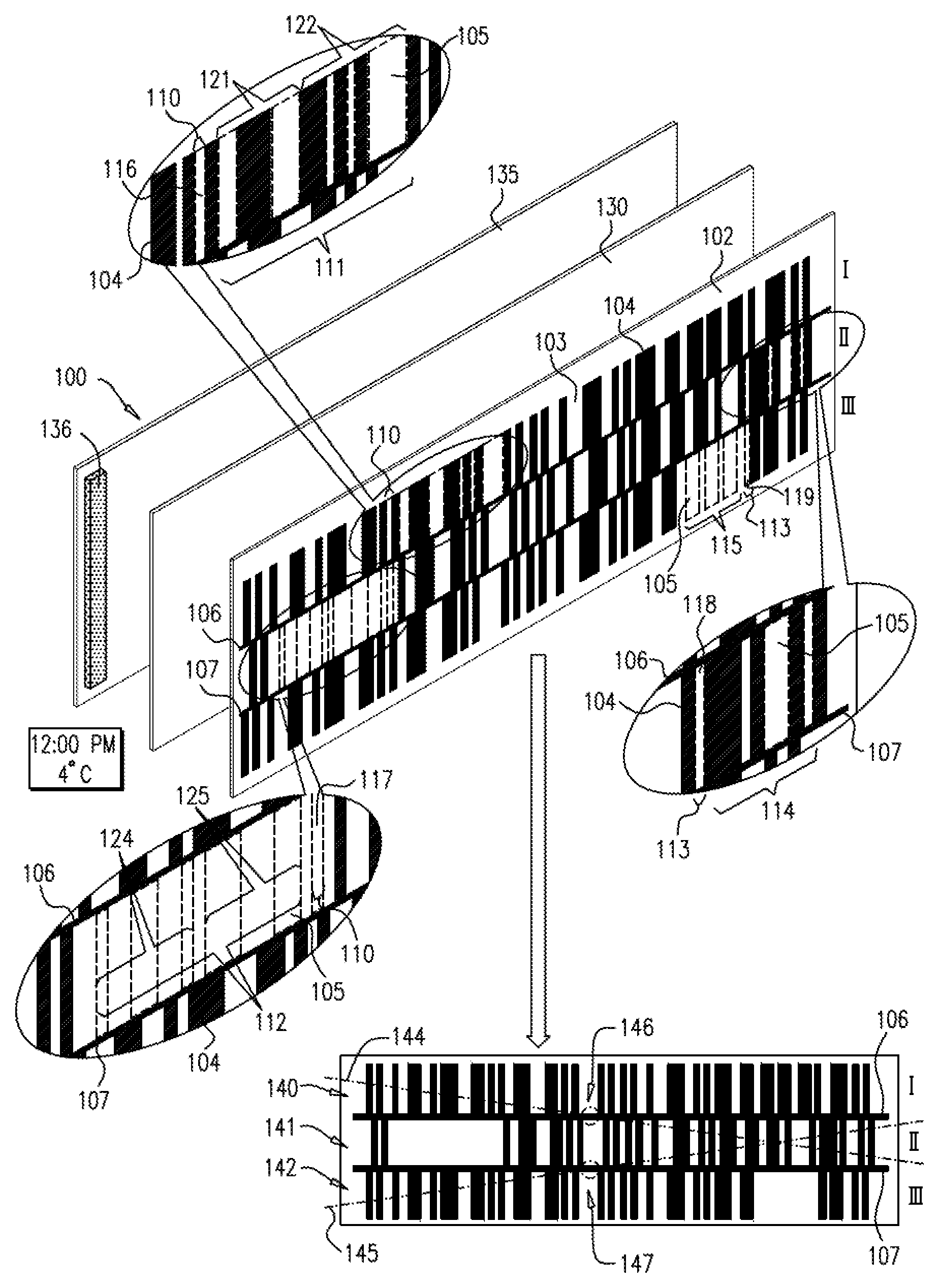
Reference is now made to FIGS. 1A-1K, which together are a simplified illustration of the construction and operation of one embodiment of a quality indicator for indicating a combination of elapsed time and temperature. The quality indicator described in FIGS. 1A-1K is operative to provide separate indications of exceedance of two different time durations, one hour, and three and a half hours, at a temperature of at least 7 degrees Celsius.
In each of FIGS. 1A-1K, the quality indicator 100 appears both in an exploded view in the middle of the drawing and in a planar view at the bottom portion of the drawing.
As seen in the exploded view in FIGS. 1A-1K, the quality indicator, here indicated by reference numeral 100, preferably includes a barcode defining layer 102, which is preferably printed on a transparent substrate. The printing on the transparent substrate preferably defines a background area 103, which is preferably printed with black ink and overprinted with white ink, a plurality of bars 104 forming part of barcodes I, II and III which are preferably printed with black ink, and a plurality of transparent areas 105, which are preferably printed with light blue ink, such as Pantone No. 645, which has a visual appearance similar to that of the black ink overprinted with white ink. Alternatively, the background area 103 and the plurality of bars 104 are printed in such colors so as to define high contrast therebetween.
The barcodes I, II and III are preferably arranged in a stacked arrangement. The barcodes I and II are preferably separated by an interposed line 106, which is preferably printed on the transparent substrate. The interposed line 106 is preferably generally parallel to the axes of the barcodes. The barcodes II and III are preferably separated by an interposed line 107, which is preferably printed on the transparent substrate. The interposed line 107 is preferably generally parallel to the axes of the barcodes.
The interposed lines 106 and 107 are preferably printed in black ink and extend in the illustrated embodiment throughout the length of the barcodes. Alternatively, the interposed lines 106 and 107 extend as necessary to prevent a barcode reader from reading parts of barcodes I, II and as a single barcode.
It is appreciated that barcodes I, II and III need not be positioned on the indicator in any particular order.
For the purposes of the present specification and claims, the phrase "transparent areas" is defined so as to include within its scope areas that are either transparent or translucent.
The transparent areas 105 preferably form part of six regions: a common colorable region 110 forming part of barcodes I and II, an additional colorable region 111 forming part of barcode I, an additional colorable region 112 forming part of barcode II, a common colorable region 113 forming part of barcodes II and III, an additional colorable region 114 forming part of barcode II and an additional colorable region 115 forming part of barcode III.
Preferably, the common colorable region 110 includes two transparent areas, transparent area 116 forming part of barcode I and transparent area 117 forming part of barcode II.
Preferably, the common colorable region 113 includes two transparent areas, transparent area 118 forming part of barcode II and transparent area 119 forming part of barcode III.
According to the embodiment illustrated in FIGS. 1A-1K, the additional colorable region 111, forming part of barcode I, appears to the right of the transparent area 116. The transparent area 116 and the transparent areas 105 which form part of the additional colorable region 111 are preferably positioned in spaces between barcode bars forming part of barcode I in its readable state, which is indicated by reference numeral 140 in the planar view of FIG. 1A.
For the purpose of the explanation which follows, the transparent areas 105 forming part of the additional colorable region 111 are grouped into two pluralities of transparent areas: 121 and 122, as illustrated in FIGS. 1A-1K.
According to the embodiment illustrated in FIGS. 1A-1K, the additional colorable region 112 forming part of barcode II appears to the left of the transparent area 117. The transparent area 117 and the transparent areas 105 which form part of the additional colorable region 112 are positioned at locations of bars which appear when barcode II is in its readable state, which is indicated by reference numeral 163 in the planar view of FIG. 1E.
For the purpose of the explanation which follows, the transparent areas 105 forming part of the additional colorable region 112 are grouped into two pluralities of transparent areas: 124 and 125, as illustrated in FIGS. 1A-1K.
According to the embodiment illustrated in FIGS. 1A-1K, the additional colorable region 114, forming part of barcode II, appears to the right of the transparent area 118. The transparent area 118 and the transparent areas 105 which form part of the additional colorable region 114 are preferably positioned in the spaces between barcode bars forming part of barcode II in its readable state, which is indicated by reference numeral 163 in the planar view of FIG. 1E.
According to the embodiment illustrated in FIGS. 1A-1K, the additional colorable region 115 forming part of barcode III appears to the left of the transparent area 119. The transparent area 119 and the transparent areas 105 which form part of the additional colorable region 115 are positioned at locations of bars which appear when barcode III is in its readable state, which is indicated by reference numeral 175 in the planar view of FIG. 1J.
Disposed behind the barcode defining layer 102 and preferably adhered thereto is a colorable element 130, such as Whatman No. 3 filter paper commercially available from Whatman International [CAT #: 1003917], which until colored is normally white. The colorable element 130 preferably extends behind the common colorable regions 110 and 113 and the additional colorable regions 111, 112, 114 and 115.
Disposed behind the barcode defining layer 102 and behind the colorable element 130 is a back layer 135. Preferably adhered to the back layer 135 rewardly of the colorable element 130 is a temperature responsive coloring element 136, such as a pad, for example, blotting paper GB003 0.8 mm thick, commercially available from Whatman international (cat # 426890), impregnated with a coloring, agent, such as Sudan Black, a black color dye [CAS: 4197-25-5], dissolved to a concentration of 0.3% in 80% Oleic Acid [CAS: 112-804-1] and 20% Laurie Alcohol [CAS: 112-53-8], which freezes at 5 degrees Celsius and melts at 7 degrees Celsius.
Turning now to FIG. 1A, as can be seen in the planar view, barcode I is initially in a readable state indicated by reference numeral 140, which is typically readable by a barcode reader as 7290003804115 and barcodes II and III are in unreadable states indicated by reference numerals 141 and 142 respectively.
As can be seen in the exploded view of FIG. 1A, the transparent area 117 and the transparent areas 105 forming part of the additional colorable region 112 forming part of barcode II are initially uncolored. As a result, as can be seen in the planar view, a plurality of bars which appear when barcode II in its readable state are missing from barcode II. The missing plurality of barcode bars results in barcode II in the initial unreadable state 141 having a low BCR level.
As can also be seen in the exploded view of FIG. 1A, the transparent area 119 and the additional colorable region 115 forming part of barcode III are initially uncolored. As a result, as can be seen in the planar view, a plurality of bars which appear when barcode III in its readable state are missing from barcode III. The missing plurality of barcode bars results in barcode III in the initial unreadable state 142 having a low BCR level.
It is appreciated that if the indicator is read by a barcode reader scanning along a line which extends across more than one barcode, for example along the line designated by reference numeral 144 which extends across barcodes I and II or along the line designated by reference numeral 145 which extends across barcodes II and III, a portion of at least one of the interposed lines 106 and 107, for example a portion of the interposed line 106 designated by reference numeral 146 or a portion of the interposed line 107 designated by reference numeral 147, is detected by the barcode reader and prevents the reading of parts of multiple barcodes, in the illustrated example parts of barcodes I and II or parts of barcodes II and III, as parts of a single barcode.
Turning to FIG. 1B, as can be seen in the exploded view, when the temperature at the quality indicator exceeds 7 degrees Celsius, such as when the temperature reaches 8 degrees Celsius, the coloring agent, indicated by reference number 150 begins to melt and be released from the coloring element 136 and begins to diffuse through the colorable element 130. The colored portions of the colorable element 130 cannot be seen through the plurality of the transparent areas 105 and, as can be seen in the planar view, barcodes I, II and III remain unchanged.
Turning to FIG. 1C, as can be seen in the exploded view, following the elapse of a certain amount of time at 8 degrees, for example 30 minutes, the coloring agent 150 continues to diffuse through the colorable element 130. As a result, portions of the colorable element 130 are visible through the plurality of transparent areas indicated by reference number 124, resulting in the appearance of a plurality of bars indicated by reference numeral 152 forming part of barcode II, as can be seen in the planar view. Barcode I remains in the readable state 140, barcode III remains in the unreadable state 142, and the changed unreadable state of barcode II is indicated by reference number 153.
The barcode bars which appear at the locations of the transparent area 117 and of the plurality of transparent areas 125 when barcode II in its readable state, indicated by reference numeral 163 in FIG. 1E, are still missing from barcode II. This missing plurality of barcode bars results in the BCR level of barcode II in the unreadable state 153 being still low.
As can be seen from the planar view of FIGS. 1B and 1C, less barcode bars are missing when barcode II is in the unreadable state 153 than when it is in the unreadable state 141. Accordingly, it is appreciated that the BCR level of barcode II in the unreadable state 153 is higher than the BCR level thereof in the unreadable state 141.
Turning to FIG. 1D, as can be seen in the exploded view, following the elapse of an additional amount of time at 8 degrees, for example another 25 minutes, the coloring agent 150 continues to diffuse through the colorable element 130. As a result, portions of the colorable element 130 are visible through the plurality of transparent areas indicated by reference number 125, resulting in the appearance of an additional plurality of bars 154 forming part of barcode II, as can be seen in the planar view. Barcode I remains in the readable state 140, barcode III remains in the unreadable state 142 and the changed unreadable state of barcode II is indicated by reference number 155. Only a single narrow barcode bar which appears at the location of the transparent area 117 when barcode II in its readable state, indicated by reference numeral 163 in FIG. 1E, is still missing from barcode II, and the missing barcode bar renders barcode II in state 155 unreadable.
It is appreciated that because only a single narrow barcode bar is missing in the unreadable state 155, the BCR level of barcode II in the unreadable state 155 is higher than that of barcode II in the unreadable states 141 and 153 described in FIGS. 1A-1C.
Turning to FIG. 1E, as can be seen in the exploded view, when a threshold is exceeded by the temperature at the indicator being at least 7 degrees Celsius for at least a predetermined cumulative amount of time, such as 8 degrees Celsius for a total of at least one hour, the coloring agent 150 diffuses through the colorable element 130, such that portions of the colorable element 130 are visible through the common colorable region 110, including the transparent areas indicated by reference numerals 116 and 117.
As a result of portions of the colorable element 130 being visible through the transparent area indicated by reference numeral 116, a space indicated by reference numeral 160, which is located between bars of barcode I in its readable state, is filled in, thereby causing barcode I to assume an unreadable state 161, as can be seen in the planar view.
As a result of portions of the colorable element 130 being visible through the transparent area indicated by reference numeral 117, a single narrow barcode bar indicated by reference numeral 162 appears in barcode II, thereby causing barcode II to assume a readable state 163, as can be seen in the planar view, which is typically readable by a barcode reader as 7290003804139.
It is appreciated that because a space preferably having a width of a single narrow barcode bar located between the bars of barcode I in its readable state is filled in, the BCR level of barcode I in the unreadable state 161 is high, similar to the BCR level of barcode II in the unreadable state 155 described in FIG. 1D.
Turning to FIG. 1F, as can be seen in the exploded view, if the temperature is at least 7 degrees Celsius for an additional amount of time, for example 8 degrees Celsius for an additional 30 minutes, the coloring agent 150 continues to diffuse through the colorable element 130, such that portions of the colorable element 130 are visible through the transparent areas indicated by reference numeral 121. As a result, a plurality of spaces indicated by reference numeral 165 located between the bars of barcode I in its readable state is filled in, as can be seen in the planar view. Barcode II remains in the readable state 163, barcode III remains in the unreadable state 142 and barcode I assumes a further unreadable state, indicated by reference number 166. As a result of the coloring of the plurality of spaces 165, the BCR level of barcode I in the unreadable state 166 decreases.
As can be seen from the planar view of FIGS. 1E and 1F, more spaces are filled in between bars of barcode I in the unreadable state 166 than in the unreadable state 161. Accordingly, it is appreciated that the BCR level of barcode I is lower in the unreadable state 166 than in the unreadable state 161.
Turning to FIG. 1G, as can be seen in the exploded view, if the temperature is at least 7 degrees Celsius for an additional amount of time, for example 8 degrees Celsius for an additional 30 minutes, the coloring agent 150 continues to diffuse through the colorable element 130, such that portions of the colorable element 130 are visible through the transparent areas indicated by reference numeral 122. As a result, an additional plurality of spaces indicated by reference numeral 167, located between the bars of barcode I in its readable state, appears colored, as can be seen in the planar view. Barcode II remains in the readable state 163, barcode III remains in the unreadable state 142 and barcode I assumes a further unreadable state 168. As a result of the coloring of the additional plurality of spaces 167, the BCR level of barcode I in the unreadable state 168 further decreases.
As can be seen from the planar view of FIGS. 1F and 1G, more spaces are filled in between barcode bars of barcode I in the unreadable state 168 than in the unreadable state 166. Accordingly, the BCR level of barcode I is lower in the unreadable state 168 than in the unreadable state 166.
Turning to FIG. 1H, as can be seen in the exploded view, if the temperature is at least 7 degrees Celsius for an additional amount of time, for example 8 degrees Celsius for an additional one hour, the coloring agent 150 continues to diffuse through the colorable element 130. The additional colored portions of the colorable element 130 are not seen through the plurality of the transparent areas 105 and, as can be seen in the planar view, barcodes I, II and III remain unchanged.
As can be seen in the exploded view of FIG. 1H, the transparent area 119 and the additional colorable region 115 forming, part of barcode III are still uncolored. As a result, as can be seen in the planar view, a plurality of bars which appear when barcode III in its readable state, indicated by reference numeral 175 in FIG. 1J, are still missing from barcode III. The missing barcode bars result in barcode III in the unreadable state 142 having a low BCR level.
Turning to FIG. 1I, as can be seen in the exploded view, following the elapse of an additional amount of tune at 8 degrees, for example another 8 minutes, the coloring agent 150 continues to diffuse through the colorable element 130. As a result, portions of the colorable element 130 are visible through the plurality of transparent areas 105 forming pan of the additional colorable region indicated by reference numeral 115, resulting in the appearance of a plurality of bars 170 forming part of barcode III, as can be seen in the planar view. Barcode I remains in the unreadable state 168, barcode II remains in the readable state 163 and the changed unreadable state of barcode III is indicated by reference number 171. Only a portion of a barcode bar which appears at the location of the transparent area 119 when barcode III in its readable state, the portion having a width of a single narrow barcode bar, is still missing from barcode III, and the missing barcode bar portion renders barcode III in state 171 unreadable.
It is appreciated that because only a portion of a barcode bar is missing in the unreadable state 171, the portion having a width of a single narrow barcode bar, the BCR level of barcode III in the unreadable state 171 is higher than that of barcode III in the unreadable state 142 described in FIG. 1A-1H.
Turning to FIG. 1J, as can be seen in the exploded view, when a second threshold is exceeded by the temperature at the indicator being at least 7 degrees Celsius for at least a second predetermined cumulative amount of time, such as 8 degrees Celsius for a total of at least three and a half hours, the coloring agent 150 diffuses through the colorable element 130, such that portions of the colorable element 130 are visible through the common colorable region 113, including the transparent areas indicated by reference numerals 118 and 119.
As a result of portions of the colorable element 130 being visible through the transparent area indicated by reference numeral 118, a space indicated by reference numeral 172, which is located between bars of barcode II in its readable state, is filled in, thereby causing barcode II to assume an unreadable state 173, as can be seen in the planar view.
As a result of portions of the colorable element 130 being visible through the transparent area indicated by reference numeral 119, a portion of a barcode appears in barcode III, the portion being indicated by reference numeral 174 and having a width of a single narrow barcode bar. As a result, barcode III assumes a readable state 175, as can be seen in the planar view, which is typically readable by a barcode reader as 7290003804122.
It is appreciated that because a space preferably having a width of a single narrow barcode bar located between the bars of barcode II in its readable state is filled in, the BCR level of barcode II in the unreadable state 173 is high, similar to the BCR level of barcode III in the unreadable state 171 described in FIG. 1I.
Turning to FIG. 1K, as can be seen in the exploded view, if the temperature is at least 7 degrees Celsius for an additional amount of time, for example 8 degrees Celsius for an additional 30 minutes, the coloring agent 150 continues to diffuse through the colorable element 130, such that portions of the colorable element 130 are visible through the transparent areas 105 forming part of the additional colorable region indicated by reference number 114. As a result, a plurality of spaces 176, located between the bars of barcode II in its readable state, is filled in, as can be seen in the planar view. Barcode I remains in the unreadable state 168, barcode III remains in the readable state 175 and barcode II assumes a further unreadable state, indicated by reference numeral 177. The plurality of spaces 176 becoming filled in causes the BCR level of barcode II in the unreadable state 177 to decrease.
As can be seen from the planar view of FIGS. 1J and 1K, more spaces are filled in between barcode bars of barcode II in the unreadable state 177 than in the unreadable state 173. Accordingly, it is appreciated that the BCR level of barcode II is lower in the unreadable state 177 than in the unreadable state 173.
It is appreciated that if the temperature drops below 7 degrees Celsius the coloring agent 150 continues to diffuse through the colorable element 130. If, after the temperature reaches 7 degrees Celsius, the temperature drops below 5 degrees Celsius, then the coloring agent 150 becomes solid and diffusion thereof through the colorable element 130 is suspended until the temperature again reaches 7 degrees Celsius.
Reference is now made to FIGS. 2A-2K, which together are a simplified illustration of the construction and operation of one embodiment of a quality indicator for indicating a combination of elapsed time and temperature. The quality indicator described in FIGS. 2A-2K is operative to provide separate indications of exceedance of two different temperatures: 7 degrees Celsius and 10 degrees Celsius, for a time duration of at least one hour at each temperature.
In each of FIGS. 2A-2K, the quality indicator 200 appears both in an exploded view in the middle of the drawing and in a planar view at the bottom portion of the drawing.
As seen in the exploded view in FIGS. 2A-2K, the quality indicator, here indicated by reference number 200, preferably includes a barcode defining layer 202, which is preferably printed on a transparent substrate. The printing on the transparent substrate preferably defines a background area 203, which is preferably printed with black ink and overprinted with white ink, a plurality of bars 204 forming part of barcodes IV, V and VI which are preferably printed with black ink, and a plurality of transparent areas 205, which are preferably printed with light blue ink, such as Pantone No. 645, which has a visual appearance similar to that of the black ink overprinted with white ink. Alternatively, the background area 203 and the plurality of bars 204 are printed in such colors so as to define high contrast therebetween.
The barcodes IV, V and VI are preferably arranged in a stacked arrangement. The barcodes IV and V are preferably separated by an interposed line 206, which is preferably printed on the transparent substrate. The interposed line 206 is preferably generally parallel to the axes of the barcodes. The barcodes V and VI are preferably separated by an interposed line 207, which is preferably printed on the transparent substrate. The interposed line 207 is preferably generally parallel to the axes of the barcodes.
The interposed lines 206 and 207 are preferably printed in black ink and extend in the illustrated embodiment throughout the length of the barcodes. Alternatively, the interposed lines 206 and 207 extend as necessary to prevent a barcode reader from reading parts of barcodes IV, V and VI as a single barcode.
It is appreciated that barcodes IV, V and VI need not be positioned on the indicator in any particular order.
The transparent areas 205 preferably form pan of six regions: a common colorable region 210 forming part of barcodes IV and V, an additional colorable region 211 forming part of barcode IV, an additional colorable region 212 forming part of barcode V, a common colorable region 213 forming part of barcodes V and VI, an additional colorable region 214 forming part of barcode V and an additional colorable region 215 forming part of barcode VI.
Preferably, the common colorable region 210 includes two transparent areas, transparent area 216 forming part of barcode IV and transparent area 217 forming part of barcode V.
Preferably, the common colorable region 213 includes two transparent areas, transparent area 218 forming part of barcode V and transparent area 219 forming part of barcode VI.
According to the embodiment illustrated in FIGS. 2A-2K, the additional colorable region 211, forming part of barcode IV, appears to the right of the transparent area 216. The transparent area 216 and the transparent areas 705 which form part of the additional colorable region 211 are preferably positioned in the spaces between barcode bars forming part of barcode IV in its readable state, which is indicated by reference numeral 240 in the planar view of FIG. 2A.
For the purpose of the explanation which follows, the transparent areas 205 forming part of the additional colorable region 211 are grouped into two pluralities of transparent areas: 221 and 222, as illustrated in FIGS. 2A-2K.
According to the embodiment illustrated in FIGS. 2A-2K, the additional colorable region 212 forming part of barcode V appears to the left of the transparent area 217. The transparent area 217 and the transparent areas 205 which form part of the additional colorable region 212 are positioned at locations of bars which appear when barcode V is in its readable state, which is indicated by reference numeral 263 in the planar view of FIG. 2E.
For the purpose of the explanation which follows, the transparent areas 205 forming part of the additional colorable region 212 are grouped into two pluralities of transparent areas: 224 and 225, as illustrated in FIGS. 2A-2K.
According to the embodiment illustrated in FIGS. 2A-2K, the additional colorable region 214, forming part of barcode V, appears to the left of the transparent area 218. The transparent area 218 and the transparent areas 205 which form part of the additional colorable region 214 are preferably positioned in the spaces between barcode bars forming part of barcode V in its readable state, which is indicated by reference numeral 263 in the planar view of FIG. 2E.
According to the embodiment illustrated in FIGS. 2A-2K, the additional colorable region 215 forming part of barcode VI appears to the right of the transparent area 219. The transparent area 219 and the transparent areas 205 which form part of the additional colorable region 215 are positioned at locations of bars which appear when barcode VI is in its readable state, which is indicated by reference numeral 275 in the planar view of FIG. 2J.
Disposed behind the barcode defining layer 202 and preferably adhered thereto is a colorable element 230, such as Whatman No. 3 filter paper commercially available from Whatman International [CAT #: 1003917], which until colored is normally white. The colorable element 230 preferably extends behind the common colorable region 210 and the additional colorable regions 211 and 212.
Also disposed behind the barcode defining layer 202 and preferably adhered thereto is an additional colorable element 232, such as Whatman No. 3 filter paper commercially available from Whatman International [CAT #: 1003917], which until colored is normally white. The colorable element 232 is preferably adjacent the colorable element 230 and preferably extends behind the common colorable region 213 and the additional colorable regions 214 and 215.
It is appreciated that instead of including two separate colorable elements, an indicator according to the present invention can include a single colorable element separated into two portions by a separator made of a material which is impermeable to ink, such as varnish.
Disposed behind the barcode defining layer 202 and behind the colorable elements 230 and 232 is a back layer 235.
Preferably adhered to the back layer 235 rearwardly of the colorable element 230 is a temperature responsive coloring element 236, such as a pad, for example, blotting paper GB003 0.8 mm thick, commercially available from Whatman international (cat #426890), impregnated with a coloring agent, such as Sudan Black, a black color dye [CAS: 4197-25-5], dissolved to a concentration of 0.3% in 80% Oleic Acid [CAS: 112-80-1] and 20% Laurie Alcohol [CAS: 112-53-8], which freezes at 5 degrees Celsius and melts at 7 degrees Celsius.
Preferably also adhered to the back layer 235 rearwardly of the colorable element 232 is a temperature responsive coloring element 238, such as a pad, for example, blotting paper GB003 0.8 mm thick, commercially available from Whatman international (cat #426890), impregnated with a coloring agent, such as Sudan Black, a black color dye [CAS: 4197-25-5], dissolved to a concentration of 0.3% in 100% Decyl Decanoate [CAS: 1654-86-0], which freezes at 9 degrees Celsius and melts at 10 degrees Celsius.
Turning now to FIG. 2A, as can be seen in the planar view, barcode IV is initially in a readable state indicated by reference numeral 240, which is typically readable by a barcode reader as 7290003804115 and barcodes V and VI are in unreadable states indicated by reference numerals 241 and 242, respectively.
As can be seen in the exploded view of FIG. 2A, the transparent area 217 and the transparent areas 205 forming part of the additional colorable region 212 forming part of barcode V are initially uncolored. As a result, as can be seen in the planar view, a plurality of bars which appear when barcode V in its readable state are missing from barcode V. The missing plurality of barcode bars results in barcode V in the initial unreadable state 241 having a low BCR level.
As can also be seen in the exploded view of FIG. 2A, the transparent area 219 and the additional colorable region 215 forming part of barcode VI are initially uncolored. As a result, as can be seen in the planar view, a plurality of bars which appear when barcode VI in its readable state are missing from barcode VI. The missing plurality of barcode bars results in barcode VI in the initial unreadable state 242 having a low BCR level.
It is appreciated that if the indicator is read by a barcode reader scanning along a line which extends across more than one barcode, for example along the line designated by reference numeral 244 which extends across barcodes IV and V or along the line designated by reference numeral 245 which extends across barcodes V and VI, a portion of at least one of the interposed lines 206 and 207, for example a portion of the interposed line 206 designated by reference numeral 246 or a portion of the interposed line 207 designated by reference numeral 247, is detected by the barcode reader and prevents the reading of parts of multiple barcodes, in the illustrated example parts of barcodes IV and V or parts of barcodes V and VI, as parts of a single barcode.
Turning, to FIG. 2B, as can be seen in the exploded view, when the temperature at the quality indicator exceeds 7 degrees Celsius, such as when the temperature reaches 8 degrees Celsius, the coloring agent, indicated by reference numeral 250 begins to melt and be released from the coloring element 236 and begins to diffuse through the colorable element 230. The colored portions of the colorable element 230 cannot be seen through the plurality of the transparent areas 205 and, as can be seen in the planar view, barcodes IV, V and VI remain unchanged.
Turning to FIG. 2C, as can be seen in the exploded view, following the elapse of a certain amount of time at 8 degrees, for example 30 minutes, the coloring agent 250 continues to diffuse through the colorable element 230. As a result, portions of the colorable element 230 are visible through the plurality of transparent areas indicated by reference numeral 224, resulting in the appearance of a plurality of bars indicated by reference numeral 252 forming part of barcode V, as can be seen in the planar view. Barcode IV remains in the readable state 240, barcode VI remains in the unreadable state 242, and the changed unreadable state of barcode V is indicated by reference number 253.
The barcode bars which appear at the locations of the transparent area 217 and of the plurality of transparent areas 225 when barcode V in its readable state, indicated by reference numeral 263 in FIG. 2E, are still missing from barcode V. This missing plurality of barcode bars results in the BCR level of barcode V in the unreadable state 253 being still low.
As can be seen from the planar view of FIGS. 2B and 2C, less barcode bars are missing when barcode V is in the unreadable state 253 than when it is in the unreadable state 241. Accordingly, it is appreciated that the BCR level of barcode V in the unreadable state 253 is higher than the BCR level thereof in the unreadable state 241.
Turning to FIG. 2D, as can be seen in the exploded view, following the elapse of an additional amount of time at 8 degrees, for example another 25 minutes, the coloring agent 250 continues to diffuse through the colorable element 230. As a result, portions of the colorable element 230 are visible through the plurality of transparent areas indicated by reference numeral 225, resulting in the appearance of an additional plurality of bars 254 firming part of barcode V, as can be seen in the planar view. Barcode IV remains in the readable state 240, barcode VI remains in the unreadable state 242 and the changed unreadable state of barcode V is indicated by reference number 255. Only a single narrow barcode bar which appears at the location of the transparent area 217 when barcode V in its readable state, indicated by reference numeral 263 in FIG. 2E, is still missing from barcode V, and the missing barcode bar renders barcode V in state 255 unreadable.
It is appreciated that because only a single barcode bar is missing in the unreadable state 255, the BCR level of barcode V in the unreadable state 255 is higher than that of barcode V in the unreadable states 241 and 253 described in FIGS. 2A-2C.
Turning to FIG. 2E, as can be seen in the exploded view, when a threshold is exceeded by the temperature at the indicator being at least 7 degrees Celsius for at least a predetermined cumulative amount of time, such as 8 degrees Celsius for a total of at least one hour, the coloring agent 250 diffuses through the colorable element 230, such that portions of the colorable element 230 are visible through the common colorable region 210, including the transparent areas indicated by reference numerals 216 and 217.
As a result of portions of the colorable element 230 being visible through the transparent area indicated by reference numeral 216, a space indicated by reference numeral 260, which is located between bars of barcode IV in its readable state, is filled in, thereby causing barcode IN to assume an unreadable state 261, as can be seen in the planar view.
As a result of portions of the colorable element 230 being visible through the transparent area indicated by reference numeral 217, a single barcode bar indicated by reference numeral 262 appears in barcode V, thereby causing barcode V to assume a readable state 263, as can be seen in the planar view, which is typically readable by a barcode reader as 7290003804139.
It is appreciated that because a space preferably having a width of a single narrow barcode bar located between the bars of barcode IV in its readable state is filled in, the BCR level of barcode IV in the unreadable state 261 is high, similar to the BCR level of barcode V in the unreadable state 255 described in FIG. 2D.
Turning to FIGS. 2F, as can be seen in the exploded view, if the temperature is at least 7 degrees Celsius for an additional amount of time, for example 8 degrees Celsius for an additional 30 minutes, the coloring agent 250 continues to diffuse through the colorable element 230, such that portions of the colorable element 230 are visible through the transparent areas indicated by reference numeral 221. As a result, a plurality of spaces indicated by reference numeral 265 located between the bars of barcode IV in its readable state are filled in, as can be seen in the planar view. Barcode V remains in the readable state 263, barcode VI remains in the unreadable state 242 and barcode IV assumes a further unreadable state, indicated by reference number 266. As a result of the plurality of spaces 265 becoming filled in, the BCR level of barcode IV in the unreadable state 266 decreases
As can be seen from the planar view of FIGS. 2E and 2F, more spaces are filled in between barcode bars of barcode IV in the unreadable state 266 than in the unreadable state 261. Accordingly, it is appreciated that the BCR level of barcode IV is lower in the unreadable state 266 than in the unreadable state 261.
Turning to FIG. 2G, as can be seen in the exploded view, if the temperature is at least 7 degrees Celsius for an additional amount of time, for example 8 degrees Celsius for an additional 30 minutes, the coloring agent 250 continues to diffuse through the colorable element 230, such that portions of the colorable element 230 are visible through the transparent areas indicated by reference number 222. As a result, an additional plurality of spaces indicated by reference numeral 267, located between the bars of barcode IV in its readable state, are filled in, as can be seen in the planar view. Barcode V remains in the readable state 263, barcode VI remains in the unreadable state 242 and barcode IV assumes a further unreadable state 268. As a result of the additional plurality of spaces 267 becoming filled in, the BCR level of barcode IV in the unreadable state 268 further decreases.
As can be seen from the planar view of FIGS. 2F and 2G, more spaces are filled in between barcode bars of barcode IV in the unreadable state 268 than in the unreadable state 266. Accordingly, the BCR level of barcode IV is lower in the unreadable state 268 than in the unreadable state 266.
It is appreciated that if the temperature drops below 7 degrees Celsius, the coloring agent 250 continues to diffuse through the colorable element 230. If, at any time after the temperature reaches 7 degrees Celsius, the temperature drops below 5 degrees Celsius, then the coloring agent 250 becomes solid and diffusion thereof through the colorable element 230 is suspended until the temperature again reaches 7 degrees Celsius.
Turning to FIG. 2H, as can be seen in the exploded view, when the temperature at the quality indicator exceeds 10 degrees Celsius, such as when the temperature reaches 12 degrees Celsius, the coloring agent, indicated by reference number 269 begins to melt and be released from the coloring element 238 and begins to diffuse through the colorable element 232. The colored portions of the colorable element 232 cannot be seen through the plurality of the transparent areas 205 and, as can be seen in the planar view, barcodes IV, V and VI remain unchanged.
As can be seen in the exploded view of FIG. 2H, the transparent area 219 and the additional colorable region 215 forming part of barcode VI are still uncolored. As a result, as can be seen in the planar view, a plurality of bars which appear when barcode VI in its readable state, indicated by reference numeral 275 in FIG. 2J, are still missing from barcode VI. The missing barcode bars result in barcode VI in the unreadable state 242 having a low BCR level.
It is appreciated that if the temperature increases above a second predetermined temperature before exceedance of a first threshold, which includes a first predetermined time duration at a first predetermined temperature, the coloring agent responsive to the second predetermined temperature melts and starts to be released from the corresponding coloring element before coloring of the common colorable region which is operative to indicate the exceedance of the first threshold. For example, in the embodiment illustrated in FIG. 2A-2K, if the temperature exceeds 10 degrees Celsius before the exceedance of one hour at a temperature of at least 7 degrees Celsius, the coloring agent 269 melts and starts to be released from the coloring element 238, before the common colorable region 210 is colored by the coloring agent 250.
Turning to FIG. 2I, as can be seen in the exploded view, following the elapse of a certain amount of time at 12 degrees, for example 55 minutes, the coloring agent 269 continues to diffuse through the colorable element 232. As a result, portions of the colorable element 232 arc visible through the plurality of transparent areas 205 forming part of the additional colorable region indicated by reference number 215, resulting in the appearance of a plurality of bars 270 forming part of barcode VI, as can be seen in the planar view. Barcode IV remains in the unreadable state 268, barcode V remains in the readable state 263 and the changed unreadable state of barcode VI is indicated by reference number 271. Only a single narrow barcode bar, which appears at the location of the transparent area 219 when barcode VI in its readable state, is still missing from barcode VI, and the missing barcode bar renders barcode VI in state 271 unreadable.
It is appreciated that because only a single narrow barcode bar is missing in the unreadable state 271, the BCR level of barcode VI in the unreadable state 271 is higher than that of barcode VI in the unreadable state 242 described in FIG. 2A-2H.
Turning to FIG. 2J, as can be seen in the exploded view, when a second threshold is exceeded by the temperature at the indicator being at least 10 degrees Celsius for at least a predetermined cumulative amount of time, such as 12 degrees Celsius for a total of at least one hour, the coloring agent 269 diffuses through the colorable element 232, such that portions of the colorable element 232 are visible through the common colorable region 213, including the transparent areas indicated by reference numerals 218 and 219.
As a result of portions of the colorable element 232 being visible through the transparent area indicated by reference numeral 218, a space indicated by reference numeral 272, which is located between bars of barcode V in its readable state, is filled in thereby causing barcode V to assume an unreadable state 273, as can be seen in the planar view.
As a result of portions of the colorable element 232 being visible through the transparent area indicated by reference numeral 219, a single narrow barcode bar indicated by reference numeral 274 appears in barcode VI, thereby causing barcode VI to assume a readable state 275, as can be seen in the planar view, which is typically readable by a barcode reader as 7290003804122.
It is appreciated that because a space preferably having a width of a single narrow barcode bar located between the bars of barcode V in its readable state is filled in, the BCR level of barcode V in the unreadable state 273 is high, similar to the BCR level of barcode VI in the unreadable state 271 described in FIG. 2I.
It is appreciated that since the distance between the common colorable region 213 and the coloring element 238 is at least equal to the distance between the common colorable region 210 and the coloring element 236, the common colorable region 213 will not become colored prior to the coloring of the common colorable region 210. Alternatively, the colorable elements 230 and 232 are made from different materials such that diffusion along the colorable element 232 is slower than diffusion along the colorable element 230.
According to an embodiment of the present invention, the indicator of the present invention can be useful to indicate the exceedance of thresholds that are not always exceeded in the same order. For example, the indicator can be used to indicate the exceedance of a first threshold and a second threshold, wherein the first threshold includes a temperature lower than the temperature of the second threshold but a time duration longer than the time duration of the second threshold.
According to this embodiment, in the indicator presented in FIGS. 2A-2K, an additional colorable area is added in barcode IV such that both barcodes IV and V become unreadable in response to exceedance of the threshold which is more likely to be indicated second, for example the second threshold described above, which includes the higher temperature.
In accordance with this embodiment, if the first threshold is exceeded before exceedance of the second threshold, exceedance of the first threshold is indicated by barcode IV becoming unreadable and by barcode V becoming readable. Exceedance of the second threshold is indicated by barcode V becoming unreadable and by barcode VI becoming readable. Barcode IV, which becomes unreadable following the exceedance of the first threshold, is still unreadable regardless of the additional colorable region.
However, if the first threshold is exceeded following exceedance of the second threshold, exceedance of the first threshold is not indicated because following exceedance of the second threshold both barcodes IV and V become unreadable.
In accordance with another embodiment of the present invention, the colorable element is not separated into two portions, and indication of exceedance of the second threshold can also result from exceedance of a second time duration at or above the predetermined temperature of the first threshold.
Turning to FIG. 2K, as can be seen in the exploded view, if the temperature is at least 10 degrees Celsius for an additional amount of time, for example 12 degrees Celsius for an additional 30 minutes, the coloring agent 269 continues to diffuse through the colorable element 232, such that portions of the colorable element 232 are visible through the transparent areas 205 forming part of the additional colorable region indicated by reference number 214. As a result, a plurality of spaces 276, located between the bars of barcode V in its readable state, is filled in, as can be seen in the planar view. Barcode IV remains in the unreadable state 268, barcode VI remains in the readable state 275 and barcode V assumes a further unreadable state, indicated by reference numeral 277. As a result of the plurality of spaces 276 becoming filled in, the BCR level of barcode V in the unreadable state 277 decreases
As can be seen from the planar view of FIGS. 2J and 2K, more spaces are filled in between barcode bars of barcode V in the unreadable state 277 than in the unreadable state 273. Accordingly, it is appreciated that the BCR level of barcode V is lower in the unreadable state 277 than in the unreadable state 273.
It is appreciated that if the temperature drops below 10 degrees Celsius the coloring agent 269 continues to diffuse through the colorable element 232. If, after the temperature reaches 10 degrees Celsius, the temperature drops below 9 degrees Celsius, then the coloring agent 269 becomes solid and diffusion thereof through the colorable element 232 is suspended until the temperature again reaches 10 degrees Celsius.
In the embodiment described in FIGS. 2A-2K, the coloring agent 269 moves along the coloring element 232 from right to left and therefore the additional colorable region 214, forming part of barcode V, appears to the left of the transparent area 218 and the additional colorable region 215, forming part of barcode VI, appears to the right of the transparent area 219. Alternatively, the coloring agent 269 moves along the coloring element 232 from left to right, and then the additional colorable region 214 appears to the right of the transparent area 218 and the additional colorable region 215 appears to the left of the transparent area 219.
The phrase "more than a single narrow barcode bar" means more than one barcode bar, the barcode bars being narrow or wide or more than a portion of a wide barcode bar, the portion being of the same width as a narrow barcode bar.
According to the embodiment illustrated in FIGS. 1A-2K, the colorable areas forming part of the additional colorable region and the common colorable region become colored sequentially. Alternatively, the colorable areas forming part of the additional colorable region and of the common colorable region become colored generally simultaneously.
The phrase "generally simultaneously", as defined in this application, means within a short time period.
It is appreciated that instead of being initially uncolored and becoming colored, a colorable area can be initially colored and become uncolored.
Preferably, as colorable areas become colored, barcode bars or portions thereof appear and spaces between barcodes or portions thereof become fill in. Alternatively, as colorable areas become colored, barcode bars or portions thereof disappear and spaces or portions thereof appear between barcode bars.
It is further appreciated that the quality indicator may be operative to provide an indication of exceedance only following actuation thereof. Alternatively, as illustrated in the description and drawings of this application, the quality indicator may be operative to provide an indication of exceedance without actuation.
According to a preferred embodiment of the present invention barcodes forming part of a quality indicator are each capable of indicating any numerical or alphanumerical sequence. Additionally or alternatively, barcodes forming part of a quality indicator are each capable of complying with any suitable barcode standard, including but not limited to EAN, UPC, 2 of 5 interleaved, code 39, code 39 extended, code 93, code 93 extended, code 128, code 128 A, B and C, ISBN, Code bar and Data Matrix. Accordingly, different barcodes forming part of the same quality indicator can comply with different barcode standards. For example, a quality indicator can include a first barcode complying with the EAN13 standard and a second barcode complying with the 2 of 5 Interleaved standard. Consequently, if the barcode reader of a checkout scanner is operative to read only the EAN13 barcode standard, then, once the first barcode becomes unreadable, the indicator no longer presents a readable barcode to the checkout scanner. However, the indicator is still readable by a barcode reader operative to read the 2 of 5 interleaved standard.
Applicant's U.S. application Ser. No. 12/469,309, filed May 20, 2009, which is hereby incorporated by reference, discloses a quality indicator which is intended to present a single readable barcode generally at any given time.
The phrase "generally simultaneously", as defined in this application, means within a short time period.
Preferably, in normal operation, a short time period means a time period of less than fifteen minutes.
The quality indicator of U.S. Ser. No. 12/469,309 includes at least two variable barcodes, such as a first barcode and a second barcode, preferably arranged in a stacked arrangement. Each of the at least two variable barcode includes at least one colorable area and has at least two visible states. One of the colorable areas in the first barcode is operative to become colored or uncolored at the same time as one of the colorable areas of the second barcode. The coloring or the uncoloring occurs, for example, upon exceedance of a time in temperature threshold.
In U.S. Ser. No. 12/469,309, a group of colorable areas which are operative to become colored or uncolored at the same time is referred to as a colorable common area.
According to an embodiment disclosed on page 14, paragraph [0051] of U.S. Ser. No. 12/469,309, the coloring of the colorable common area which forms part of the first and the second barcodes in a quality indicator causes the visible state of the first barcode, which is initially readable, to become unreadable and, at the same time, causes the visible state of the second barcode, which is initially not readable, to become readable. Accordingly, the quality indicator of U.S. Ser. No. 12/469,309 presents a single readable barcode both before and after exceedance of a threshold.
The colorable common areas disclosed in U.S. Ser. No. 12/469,309 preferably include a single colorable area per barcode and preferably have the width of a single barcode bar. Accordingly, the difference between the readable state and the unreadable state of the barcodes disclosed in U.S. Ser. No. 12/469,309 is preferably a single barcode bar.
A problem may occur if a barcode is read by a barcode reader when the barcode is in an unreadable state. The more similar the unreadable state of a barcode is to the readable state thereof, the higher is the probability that the unreadable barcode will be erroneously read by a barcode reader. If a barcode reader erroneously reads either the first or the second barcode in the quality indicator of U.S. Ser. No. 12/469,309 when that barcode is in an unreadable state, the barcode reader may read a barcode presenting incorrect information. This problem can occur in situations such as described below, with reference to the embodiment disclosed on page 14, paragraph [0051] U.S. Ser. No. 12/469,309:
In a first situation, the second barcode, which is not readable prior to exceedance of a threshold, is erroneously read by a barcode reader notwithstanding that the colorable common area has not yet become colored. At the same time, the first barcode remains readable because the first barcode becomes unreadable only upon coloring of the colorable common area. As a result, by reading the second unreadable barcode, the barcode reader reads a barcode presenting incorrect information.
In a second situation, the first barcode, which is readable prior to exceedance of a threshold, is erroneously still read by a barcode reader following exceedance of the threshold, notwithstanding that the colorable common area became colored and rendered the first barcode unreadable. At the same time, the second barcode becomes readable by virtue of the coloring of the colorable common area. As a result, by reading the first unreadable barcode, the barcode reader reads a barcode presenting incorrect information.
A group of colorable areas corresponding to the colorable common area disclosed in U.S. Ser. No. 12/469,309 and which are operative to become colored or uncolored at the same time, is hereinafter referred to as a common colorable region.
The common colorable region preferably has a width of a single narrow barcode bar. Alternatively, the common colorable region is wider than a single narrow barcode bar.
The present application provides an improvement to the quality indicator described in U.S. Ser. No. 12/469,309. This improvement alleviates the above problem by preferably including as part of a barcode at least one additional set of colorable areas, in addition to the common colorable region.
Each additional set of colorable areas, hereinafter referred to as an additional colorable region, preferably includes at least one colorable area, forms part of a single barcode and is configured to reduce the barcode readability level of the barcode of which it forms a part. Preferably, an additional colorable region includes more than one colorable area. Alternatively, an additional colorable region includes a single colorable area.
The phrase "barcode readability level" or "BCR level" of a barcode in an unreadable state reflects the likelihood that a barcode reader will erroneously read the barcode when it is in that unreadable state. Accordingly, an unreadable barcode having a low BCR level is not likely to be erroneously read by a barcode reader.
In accordance with a preferred embodiment of the present invention, in the first situation described above, the additional colorable region forms part of the initially unreadable second barcode, and includes an initially uncolored set of colorable areas. The initially uncolored set of colorable areas is preferably positioned at location of barcode bars which appear in the second barcode in its readable state. As a result, more than a single narrow barcode bar is missing from the second barcode. It is appreciated that as a result of more than a single narrow barcode bars being missing, the BCR level of the unreadable second barcode decreases and becomes lower than the BCR level of the unreadable second barcode in U.S. Ser. No. 12/469,309, wherein only a single barcode bar is missing.
Preferably, "more than a single narrow barcode bar" means more than one barcode bar, the barcode bars being narrow or wide. Alternatively, "more than a single narrow barcode bar means more than a portion of a wide barcode bar, the portion being at the same width as a narrow barcode bar.
It is appreciated that portions of barcode bars can be missing as a result of set of colorable areas not being colored.
In accordance with another preferred embodiment of the present invention, in the second situation described above, the additional colorable region forms part of the initially readable first barcode and includes an initially uncolored set of colorable areas. The initially uncolored set of colorable areas is preferably positioned in spaces between barcode bars which form part of the first barcode in its readable state, and when uncolored do not interfere with the readability of the first barcode.
Preferably, following exceedance of a threshold, colorable areas forming part of the common colorable region and of the additional colorable region become colored, thereby causing the first barcode to become unreadable. The coloring of the additional colorable region results in multiple spaces between bars of the first barcode becoming filled in, thereby decreasing the BCR level of the first barcode and causing it to be lower than that of the unreadable state of the first barcode described in U.S. Ser. No. 12/469,309, which has only a space having a width of a single barcode bar filled in relative to the readable state thereof.
It is appreciated that instead of multiple spaces becoming filled in between bars of the first barcode, a space which is wider than a single narrow barcode bar can become filled in.
According to the embodiment illustrated in FIGS. 3A-4K, the colorable areas forming part of the additional colorable region and the common colorable region become colored sequentially. Alternatively, the colorable areas forming part of the additional colorable region and of the common colorable region become colored generally simultaneously.
It is appreciated that a plurality of spaces between barcode bars which become filled in as a result of coloring of a set of colorable areas can include spaces which are partially filled in.
It is appreciated that instead of being initially uncolored and becoming colored, a colorable area can be initially colored and become uncolored.
Preferably, as colorable areas become colored, barcode bars or portions thereof appear and spaces between barcodes or portions thereof become filled in. Alternatively, as colorable areas become colored, barcode bars or portions thereof disappear and spaces or portions thereof form between barcode bars.
It is further appreciated that the quality indicator may be operative to provide an indication of exceedance only following actuation thereof. Alternatively, as illustrated in the description and drawings of this application, the quality indicator may be operative to provide an indication of exceedance without actuation.
According to a preferred embodiment of the present invention barcodes forming part of a quality indicator are each capable of indicating any numerical or alphanumerical sequence. Additionally or alternatively, barcodes forming part of a quality indicator are each capable of complying with any suitable barcode standard, including but not limited to RAN, UPC, 2 of 5 interleaved, code 39, code 39 extended, code 93, code 93 extended, code 128, code 128 A, B and C, ISBN, Code bar and Data Matrix. Accordingly, different barcodes forming part of the same quality indicator can comply with different barcode standards. For example, a quality indicator can include a first barcode complying with the EAN13 standard and a second barcode complying with the 2 of 5 interleaved standard. Consequently, if the barcode reader of a checkout scanner is operative to read only the EAN13 barcode standard, then, once the first barcode becomes unreadable, the indicator no longer presents a readable barcode to the checkout scanner. However, the indicator is still readable by a barcode reader operative to read the 2 of 5 interleaved standard.
Reference is now made to FIGS. 3A-3K, which together are a simplified illustration of the construction and operation of one embodiment of a quality indicator for indicating a combination of elapsed time and temperature. The quality indicator described in FIGS. 3A-3K is operative to provide separate indications of exceedance of two different time durations, one hour, and three and a half hours, at a temperature of at least 21 degrees Celsius.
In each of FIGS. 3A-3K, the quality indicator 300 appears both in an exploded view at the top left portion of the drawing and in a planar view at the bottom right portion of the drawing.
As seen in the exploded view in FIGS. 3A-3K, the quality indicator, here indicated by reference number 300, preferably includes a barcode defining layer 302, which is preferably printed on a transparent substrate. The printing on the transparent substrate preferably defines a background area 303, which is preferably printed with black ink and overprinted with white ink, a plurality of bars 304 forming part of barcodes I, II and III which are preferably printed with black ink, and a plurality of transparent areas 305, which are preferably printed with light blue ink, such as Pantone No. 645, which has a visual appearance similar to that of the black ink overprinted with white ink. Alternatively, the background area 303 and the plurality of bars 304 are printed in such colors so as to define high contrast therebetween.
For the purposes of the present specification and claims, the phrase "transparent areas" is defined so as to include within its scope areas that are either transparent or translucent.
The barcodes I, II and III are preferably arranged in a stacked arrangement and the transparent areas 305 preferably form part of six regions: a common colorable region 310 forming part of barcodes I and II, an additional colorable region 311 forming part of barcode I, an additional colorable region 312 forming part of barcode II, a common colorable region 313 forming part of barcodes II and III, an additional colorable region 314 forming part of barcode it and an additional colorable region 315 forming part of barcode III.
It is appreciated that barcodes I, II and III need not be positioned on the indicator in an particular order.
It is also appreciated that the spaces which appear in FIGS. 3A-3K between barcode I and barcode I
References
D00000
D00001
D00002
D00003
D00004
D00005
D00006
D00007
D00008
D00009
D00010
D00011
D00012

D00013

D00014

D00015

D00016

D00017

D00018

D00019

D00020

D00021

D00022
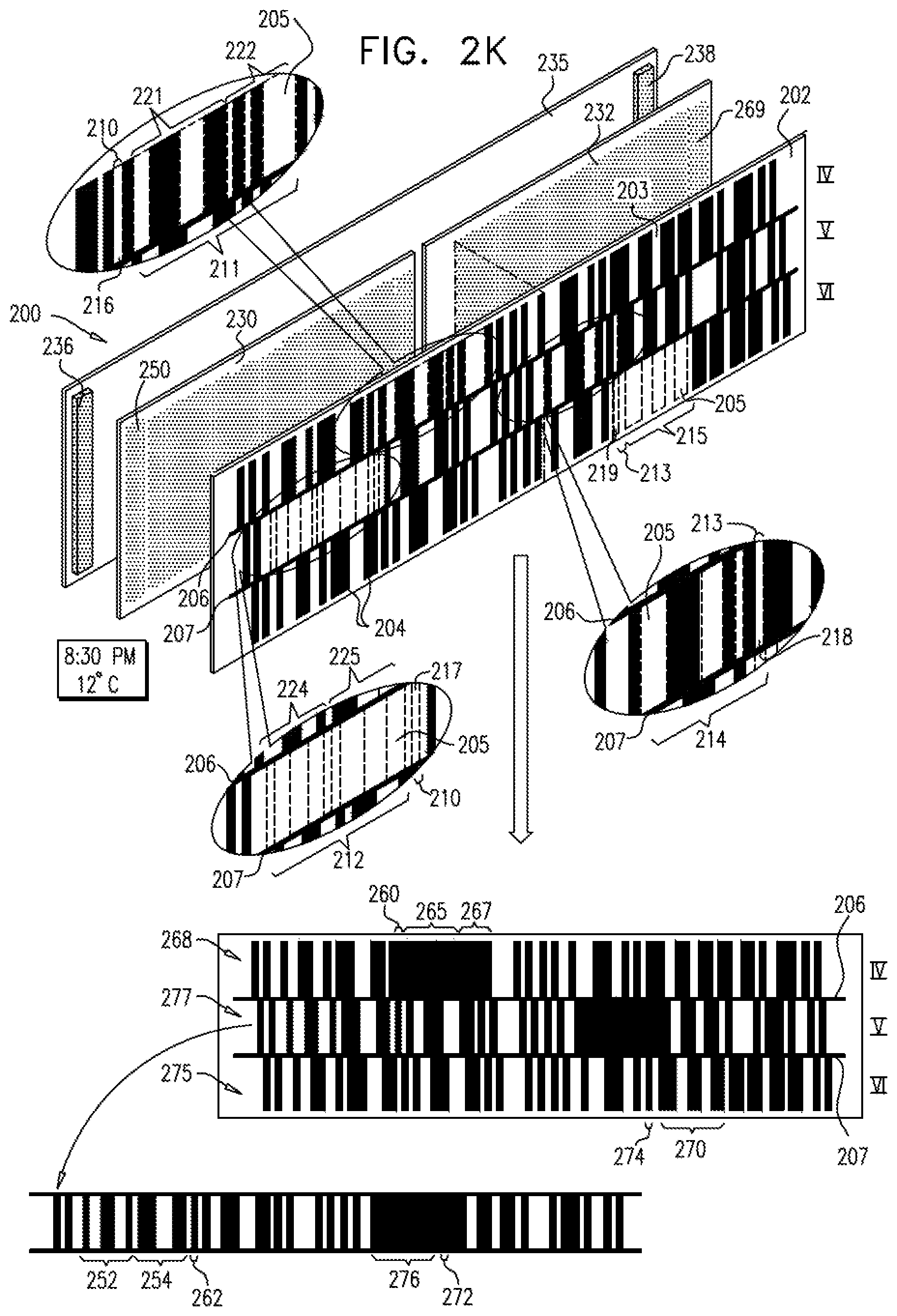
D00023

D00024

D00025

D00026

D00027

D00028

D00029

D00030

D00031

D00032

D00033

D00034

D00035

D00036

D00037

D00038

D00039

D00040
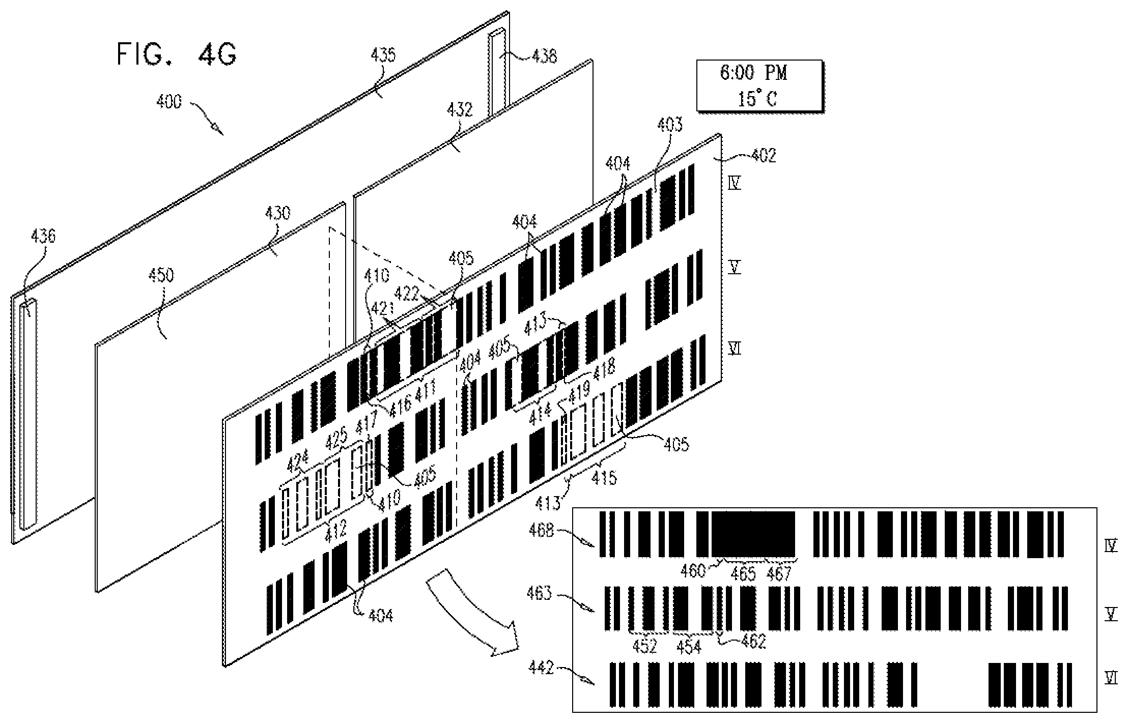
D00041

D00042

D00043

D00044

XML
uspto.report is an independent third-party trademark research tool that is not affiliated, endorsed, or sponsored by the United States Patent and Trademark Office (USPTO) or any other governmental organization. The information provided by uspto.report is based on publicly available data at the time of writing and is intended for informational purposes only.
While we strive to provide accurate and up-to-date information, we do not guarantee the accuracy, completeness, reliability, or suitability of the information displayed on this site. The use of this site is at your own risk. Any reliance you place on such information is therefore strictly at your own risk.
All official trademark data, including owner information, should be verified by visiting the official USPTO website at www.uspto.gov. This site is not intended to replace professional legal advice and should not be used as a substitute for consulting with a legal professional who is knowledgeable about trademark law.