Temperature controlled method to liquefy gas and a production plant using the method
Lourenco , et al. Feb
U.S. patent number 10,571,187 [Application Number 14/386,323] was granted by the patent office on 2020-02-25 for temperature controlled method to liquefy gas and a production plant using the method. This patent grant is currently assigned to 1304338 Alberta Ltd, 1304342 Alberta Ltd. The grantee listed for this patent is 1304338 Alberta Ltd, 1304342 Alberta Ltd. Invention is credited to Jose Lourenco, MacKenzie Millar.


| United States Patent | 10,571,187 |
| Lourenco , et al. | February 25, 2020 |
Temperature controlled method to liquefy gas and a production plant using the method
Abstract
A method for liquefying gas involving pre-treating the gas stream in a pre-treater to remove impurities, and then passing the gas stream through a first flow path of a first heat exchanger to lower a temperature of the gas stream. The gas stream is then passed through the gas expansion turbine to lower a pressure of the gas stream and further decrease the temperature of the gas stream. The gas stream is then passed into a primary separator to separate the gas stream into a liquid stream and a cold gas stream. The liquid stream is collected. Selected quantities of the cold gas stream are passed through a second flow path of the first heat exchanger whereby a heat exchange takes place to cool the gas stream flowing through the first flow path to maintain the temperature of the gas stream entering the gas expansion turbine at a temperature which promotes the production of liquids.
| Inventors: | Lourenco; Jose (Edmonton, CA), Millar; MacKenzie (Edmonton, CA) | ||||||||||
|---|---|---|---|---|---|---|---|---|---|---|---|
| Applicant: |
|
||||||||||
| Assignee: | 1304338 Alberta Ltd (Edmonton,
CA) 1304342 Alberta Ltd (Edmonton, CA) |
||||||||||
| Family ID: | 49209625 | ||||||||||
| Appl. No.: | 14/386,323 | ||||||||||
| Filed: | March 21, 2013 | ||||||||||
| PCT Filed: | March 21, 2013 | ||||||||||
| PCT No.: | PCT/CA2013/050232 | ||||||||||
| 371(c)(1),(2),(4) Date: | September 18, 2014 | ||||||||||
| PCT Pub. No.: | WO2013/138940 | ||||||||||
| PCT Pub. Date: | September 26, 2013 |
Prior Publication Data
| Document Identifier | Publication Date | |
|---|---|---|
| US 20150107297 A1 | Apr 23, 2015 | |
Foreign Application Priority Data
| Mar 21, 2012 [CA] | 2772479 | |||
| Current U.S. Class: | 1/1 |
| Current CPC Class: | F25J 1/0035 (20130101); F25J 1/0047 (20130101); F25J 1/0202 (20130101); F25J 1/0232 (20130101); F25J 1/004 (20130101); F25J 1/0022 (20130101); F25J 1/0045 (20130101); F25J 2245/02 (20130101); F25J 2220/00 (20130101); F25J 2220/64 (20130101); F25J 2205/02 (20130101) |
| Current International Class: | F25J 1/00 (20060101); F25J 1/02 (20060101) |
References Cited [Referenced By]
U.S. Patent Documents
| 2168438 | August 1939 | Carrier |
| 3002362 | October 1961 | Morrison |
| 3152194 | October 1964 | Pohl et al. |
| 3184926 | May 1965 | Blake |
| 3280575 | October 1966 | Drake |
| 3312073 | April 1967 | Jackson et al. |
| 3367122 | February 1968 | Tutton |
| 3653220 | April 1972 | Foster et al. |
| 3735600 | May 1973 | Dowdell et al. |
| 3747359 | July 1973 | Streich |
| 3754405 | August 1973 | Rosen |
| 3792590 | February 1974 | Lofredo et al. |
| 3846993 | November 1974 | Bates |
| 3859811 | January 1975 | Duncan |
| 3919853 | November 1975 | Rojey |
| 3962881 | June 1976 | Muska |
| 4033735 | July 1977 | Swenson |
| 4279130 | July 1981 | Finch et al. |
| 4418530 | December 1983 | Bodrov et al. |
| 4424680 | January 1984 | Rothchild |
| 4430103 | February 1984 | Gray et al. |
| 4444577 | April 1984 | Perez |
| 4617039 | October 1986 | Buck |
| 4681612 | July 1987 | O'Brien et al. |
| 4710214 | December 1987 | Sharma et al. |
| 4751151 | June 1988 | Healy et al. |
| 4869740 | September 1989 | Campbell et al. |
| 4907405 | March 1990 | Polizzotto |
| 4936888 | June 1990 | DeLong |
| 5137558 | August 1992 | Agrawal |
| 5295350 | March 1994 | Child et al. |
| 5329774 | July 1994 | Tanguay et al. |
| 5425230 | June 1995 | Shpak |
| 5440894 | August 1995 | Schaeffer et al. |
| 5669234 | September 1997 | Houser |
| 5678411 | October 1997 | Matsumura et al. |
| 5685170 | November 1997 | Sorensen |
| 5782958 | July 1998 | Rojey et al. |
| 5799505 | September 1998 | Bonaquist et al. |
| 5953935 | September 1999 | Sorensen |
| 6023942 | February 2000 | Thomas |
| 6089022 | July 2000 | Zednik et al. |
| 6089028 | July 2000 | Bowen et al. |
| 6131407 | October 2000 | Wissolik |
| 6138473 | October 2000 | Boyer-Vidal |
| 6182469 | February 2001 | Campbell et al. |
| 6196021 | March 2001 | Wissolik |
| 6266968 | July 2001 | Redlich |
| 6286315 | September 2001 | Staehle |
| 6378330 | April 2002 | Minta et al. |
| 6432565 | August 2002 | Haines |
| 6517286 | February 2003 | Latchem |
| 6526777 | March 2003 | Campbell et al. |
| 6581409 | June 2003 | Wilding et al. |
| 6606860 | August 2003 | McFarland |
| 6640555 | November 2003 | Cashin |
| 6662589 | December 2003 | Roberts et al. |
| 6694774 | February 2004 | Rashad et al. |
| 6739140 | May 2004 | Bishop et al. |
| 6751985 | June 2004 | Kimble |
| 6889523 | May 2005 | Wilkinson |
| 6932121 | August 2005 | Shivers, III |
| 6945049 | September 2005 | Madsen |
| 7051553 | May 2006 | Mak et al. |
| 7107788 | September 2006 | Patel et al. |
| 7155917 | January 2007 | Baudat |
| 7219502 | May 2007 | Nierenberg |
| 7257966 | August 2007 | Lee et al. |
| 7377127 | May 2008 | Mak |
| 8899074 | December 2014 | Wilding |
| 2002/0170297 | November 2002 | Quine et al. |
| 2003/0008605 | January 2003 | Hartford, Jr. et al. |
| 2003/0019219 | January 2003 | Viegas et al. |
| 2003/0051875 | March 2003 | Wilson |
| 2003/0182947 | October 2003 | Kimble et al. |
| 2003/0196452 | October 2003 | Wilding et al. |
| 2004/0065085 | April 2004 | Madsen |
| 2005/0086974 | April 2005 | Steinbach et al. |
| 2005/0244277 | November 2005 | Hurst, Jr. et al. |
| 2006/0213222 | September 2006 | Whitesell |
| 2006/0213223 | September 2006 | Wilding et al. |
| 2006/0242970 | November 2006 | Yang et al. |
| 2007/0062216 | March 2007 | Mak et al. |
| 2007/0107465 | May 2007 | Turner et al. |
| 2008/0016910 | January 2008 | Brostow et al. |
| 2009/0113928 | May 2009 | Vandor et al. |
| 2009/0249829 | October 2009 | Lourenco et al. |
| 2009/0282865 | November 2009 | Martinez et al. |
| 2011/0094263 | April 2011 | Wilding et al. |
| 2012/0060554 | March 2012 | Schmidt |
| 2012/0169049 | July 2012 | Oxner et al. |
| 2013/0333416 | December 2013 | Lourenco et al. |
| 1048876 | Feb 1979 | CA | |||
| 2 422 893 | Feb 2002 | CA | |||
| 2 467 338 | Jul 2003 | CA | |||
| 2 516 785 | Sep 2004 | CA | |||
| 2 552 366 | Jul 2005 | CA | |||
| 2 299 695 | Jul 2007 | CA | |||
| 2 318 802 | Feb 2008 | CA | |||
| 2 777 760 | May 2011 | CA | |||
| 2 728 716 | Jul 2012 | CA | |||
| 2 515 999 | Dec 2012 | CA | |||
| 1615415 | May 2005 | CN | |||
| 1019448706 | Jan 2011 | CN | |||
| 44 16 359 | Oct 1998 | DE | |||
| 0 482 222 | Apr 1992 | EP | |||
| 0 566 285 | Oct 1993 | EP | |||
| 0 635 673 | Jan 1995 | EP | |||
| 0 780 649 | Jun 1997 | EP | |||
| 2 420 081 | Oct 1979 | FR | |||
| 1011453 | Dec 1965 | GB | |||
| 2 103 354 | Feb 1983 | GB | |||
| 3-236589 | Oct 1991 | JP | |||
| 5-263998 | Oct 1993 | JP | |||
| 2002-295799 | Oct 2002 | JP | |||
| 2 180 420 | Mar 2002 | RU | |||
| 2 232 342 | Jul 2004 | RU | |||
| 94/11626 | May 1994 | WO | |||
| 97/01069 | Jan 1997 | WO | |||
| 98/59205 | Dec 1998 | WO | |||
| 00/52403 | Sep 2000 | WO | |||
| 03/081038 | Oct 2003 | WO | |||
| 03/095913 | Nov 2003 | WO | |||
| 03/095914 | Nov 2003 | WO | |||
| 2004/010480 | Jan 2004 | WO | |||
| 2004/109180 | Dec 2004 | WO | |||
| 2004/109206 | Dec 2004 | WO | |||
| 2005/045337 | May 2005 | WO | |||
| 2006/004723 | Jan 2006 | WO | |||
| 2006/019900 | Feb 2006 | WO | |||
| 2006/036441 | Apr 2006 | WO | |||
| 2009/061777 | May 2009 | WO | |||
Other References
|
International Search Report and Written Opinion dated Aug. 1, 2013, issued in corresponding International Application No. PCT/CA2013/050232, filed Mar. 21, 2013, 13 pages. cited by applicant . Hudson, H.M., et al., "Reducing Treating Requirements for Cryogenic NGL Recovery Plants," Proceedings of the 80th Annual Convention of the Gas Processors Association, Mar. 12, 2001, San Antonio, Texas, 15 pages. cited by applicant. |
Primary Examiner: Raymond; Keith M
Attorney, Agent or Firm: Christensen O'Connor Johnson Kindness, PLLC
Claims
What is claimed is:
1. A method for liquefying gas, comprising: obtaining a gas stream from a transmission pipeline at a pipeline pressure; pre-treating the gas stream in a pre-treater to remove impurities and produce a pre-treated gas stream; passing the pre-treated gas stream through a first flow path of a first heat exchanger to lower a temperature of the pre-treated gas stream to produce a cooled gas stream; passing the cooled gas stream from the first heat exchanger through a gas expansion turbine to produce an expanded gas stream by lowering a pressure of the cooled gas stream to about atmospheric pressure and further decrease the temperature of the cooled gas stream; passing the expanded gas stream into a primary separator to separate the expanded gas stream into Liquid Natural Gas (LNG) and a cold gas stream; collecting the LNG; passing selective quantities of the cold gas stream through a second flow path of the first heat exchanger whereby a heat exchange takes place in the first heat exchanger to cool the pre-treated gas stream flowing through the first flow path to maintain the temperature of the cooled gas stream entering the gas expansion turbine at a temperature which promotes the production of liquids; mixing a slip stream of the collected LNG into the cold gas stream via a mixer that is positioned downstream of the first heat exchanger and upstream of the gas expansion turbine, the slip stream causing natural gas liquids (NGLs) in the cold gas stream to condense to produce a mixed phase stream; passing the mixed phase stream through a preliminary separator positioned downstream of the mixer and upstream of the gas expansion turbine to separate the condensed NGLs from the mixed phase stream; and directing the remaining mixed phase stream to the gas expansion turbine.
2. The method of claim 1, further comprising the step of compressing a portion of the cold gas stream to the pipeline pressure and returning the compressed cold gas stream to the transmission pipeline downstream.
Description
FIELD OF THE INVENTION
The present invention relates to a method to liquefy natural gas from a transmission gas pipeline. The described process was developed to efficiently produce liquid natural gas (LNG).
BACKGROUND OF THE INVENTION
LNG is a natural gas that has been cooled to a cryogenic condition to condense methane, the natural gas main component. A temperature of approximately -161 C is required to produce and keep natural gas in a liquid state at standard atmospheric pressure. Liquefaction reduces the volume by approximately 600 times thus making it more economical to transport over great distances versus traditional pipelines. At present, LNG is primarily transported across continents thus making it available throughout the world. LNG is also produced in small scale liquefaction plants to supply peak saving demands, as well as to make available natural gas to regions that need it but where it is not economical or technically feasible to build pipelines.
There are differences in liquefaction selection processes for large versus small LNG plants. For large plants, the main criteria is minimization of capital cost whereas the minimization of energy consumption is left as a second objective. These two objectives can also go together; thus an optimization of the efficiency of the plant may involve a reduction in the investment of the equipment. On the other hand, a higher efficiency can result in an increase in LNG production, so the efficiency factor has a significant impact on the plant economics. In small to medium LNG plants, it is not the efficiency, but other factors such as simplicity, modularization, ease of maintenance, operation and installation that have an higher criteria when selecting a liquefaction technology. The direct consequence of these different selection criteria is that liquefaction technologies for small to medium scale applications are not the same as the ones that are used in large LNG plants.
The two main groups of liquefaction technologies are the mixed refrigerant technologies and expansion based technologies. The mixed refrigerant technologies are "condensing type" processes, where the refrigerant used for the liquefaction makes use of its latent heat of vaporization to cool the natural gas. The expansion based technologies are processes where the refrigerant is always in gas phase and only makes use of its sensible heat to cool the natural gas.
The following mixed refrigerant technologies are the most representative processes in the industry: PRICO (Poly Refrigerated Integrated Cycle Operation) is licensed by Black and Veatch and it consists of one cycle of mixed refrigerant (a mixture of methane, ethane, propane, butane, nitrogen and sometimes isopentane), the advantages claimed by the licensor are operating flexibility, modular design and reduced refrigerant inventory. The AP-M (Air Products) is licensed by APCI, is a single mixed refrigerant that is vaporized at two different levels of pressure. The dual pressure cycle is more efficient than the single pressure cycle, resulting in smaller heat exchangers and compressor. The LiMuM (Linde Multistage Mixed Refrigerant) is licensed by Linde and consists of a spiral wound heat exchanger and one 3-stage single mixed refrigeration loop for the pre-cooling, liquefaction and sub-cooling of the natural gas. This process allows for high capacity throughput. PCMR (Pre-cooled Mixed Refrigerant) is licensed by Kryopak and consists of a pre-cooling stage (ammonia or propane cycle) followed by a single mixed refrigerant cycle, where the mixed refrigerant is a mixture of nitrogen, methane, ethane, propane and butanes, this process is used primarily in small plants. OSMR (Optimized Single Mixed Refrigerant) is licensed by LNG Limited, the process is a single mixed refrigerant process complemented with a standard package ammonia absorption process. The utilization of an ammonia process improves the efficiency of the process and an increase in LNG output compared to traditional single mixed refrigerant processes. In all of the above mixed refrigerant technologies, the main differences between them are the composition of the mixed refrigerant (although the refrigerants are the same i.e.; nitrogen, methane, ethane, etc.), the metallurgy of the heat exchangers, the orientation of the equipment and the operations set points. In all the mixed refrigerants processes, the objective of innovation is to increase efficiency, reducing capital and operating costs.
The expansion based technologies have various processes based on the use of nitrogen as a refrigerant to liquefy natural gas, the N.sub.2 expansion cycle. Some of these processes use a single cycle, others use a dual expansion cycle and in other cases a pre-cooling cycle is added to improve efficiency. Several licensors i.e., APCI, Hamworthy, BHP Petroleum Pty, Mustang Engineering and Kanfa Oregon offer the N.sub.2 expansion cycles processes, and they differ by proprietary process arrangement. In all these processes, the cooling is provided by an external refrigeration plant using nitrogen expanders. The Niche LNG process is licensed by CB&I Lummus, consists of two cycles: one cycle uses methane as a refrigerant and the other uses nitrogen. The methane provides cooling at moderate and warm levels while the nitrogen cycle provides refrigeration at the lowest temperature level. The OCX process is licensed by Mustang Engineering and is based on the use of the inlet gas as a refrigerant in an open refrigerant cycle with turbo-expanders, there are variations such as OCX-R which adds a closed loop propane refrigerant to the OCX process and OCX-Angle which incorporates LPG recovery.
As demonstrated, presently there are many variations and processes to liquefy LNG. All of the processes operate based on the expansion of low boiling fluids be it through expanders or JT valves, be it closed or open cycle, the difference between them is in the process efficiencies which result in lower capital and operating costs per unit of LNG produced.
What is required is an alternative method to liquefy gas, such as LNG.
SUMMARY OF THE INVENTION
According to one aspect, there is provided a method for liquefying gas where a gas stream is passed through a gas expansion turbine. The method involves pre-treating the gas stream in a pre-treater to remove impurities, and then passing the gas stream through a first flow path of a first heat exchanger to lower a temperature of the gas stream. The gas stream is then passed through the gas expansion turbine to lower a pressure of the gas stream and further decrease the temperature of the gas stream. The gas stream is then passed into a primary separator to separate the gas stream into a liquid stream and a cold gas stream. The liquid stream is collected. Selected quantities of the cold gas stream are passed through a second flow path of the first heat exchanger whereby a heat exchange takes place to cool the gas stream flowing through the first flow path to maintain the temperature of the gas stream entering the gas expansion turbine at a temperature which promotes the production of liquids.
The method will hereinafter, as applied to the natural gas. The impurities removed are carbon dioxide and water. The liquids collected are natural gas liquids.
Although beneficial results may be obtained through the use of the method, as described above, greater efficiencies can be achieved through the use of a recycle stream. The recycle stream already has impurities removed. This involves a step of compressing the cold gas stream in a compressor after the cold gas stream has passed through the first heat exchanger to create a recycled gas stream and directing the recycled gas stream into the gas stream downstream of the pre-treater and upstream of the first heat exchanger.
Passing the recycled gas stream through the compressor will unavoidably raise the temperature of the recycled gas stream. It is, therefore, preferred that a step be included of passing the recycled gas stream through a first flow path of a second heat exchanger downstream of the compressor to lower the temperature of the recycled gas stream prior to the recycled gas stream being directed into the gas stream.
In accordance with the teachings of this method, a steady state will be reached in which a ratio of the recycled gas stream entering the gas stream is maintained constant.
In a variation of the method, where the liquids one wishes to collect are Liquid Natural Gas (LNG), a further step is included of mixing a slip stream of liquid natural gas (LNG) drawn from the primary separator into the gas stream via a mixer positioned downstream of the first heat exchanger and upstream of the gas expansion turbine.
In another variation of the method, a further step may be taken of passing the gas stream through a preliminary separator positioned downstream of the mixer and upstream of the gas expansion turbine to separate natural gas liquids (NGLs) from the gas stream, collecting the NGLs and directing the gas stream to the gas expansion turbine.
An advantage of the above method is that it can operate without external power inputs, resulting in substantial savings in both capital and operating costs. The above described method was developed with a view to collecting natural gas liquids and liquefying natural gas to form Liquid Natural Gas (LNG).
BRIEF DESCRIPTION OF THE DRAWINGS
These and other features of the invention will become more apparent from the following description in which reference is made to the appended drawings, the drawings are for the purpose of illustration only and are not intended to in any way limit the scope of the invention to the particular embodiment or embodiments shown, wherein:
FIG. 1 is a schematic diagram of a facility equipped with a gas pre-treatment, an heat exchanger, an expander and a compressor to produce LNG.
FIG. 2 is a schematic diagram of a facility equipped with an alternate cooling medium for the compression of the recycled vapour fraction.
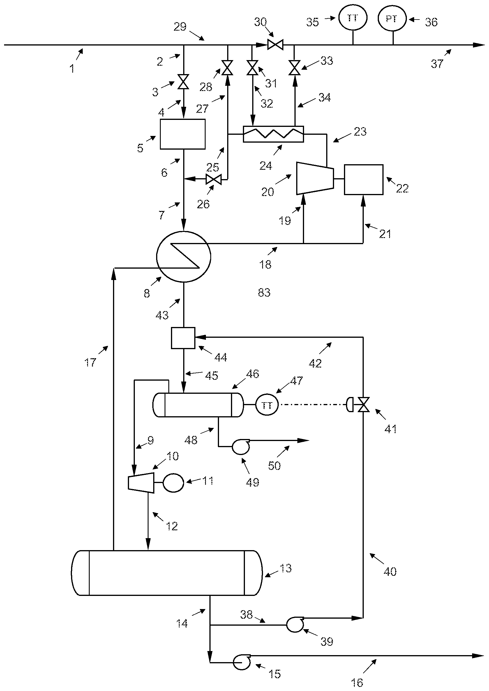
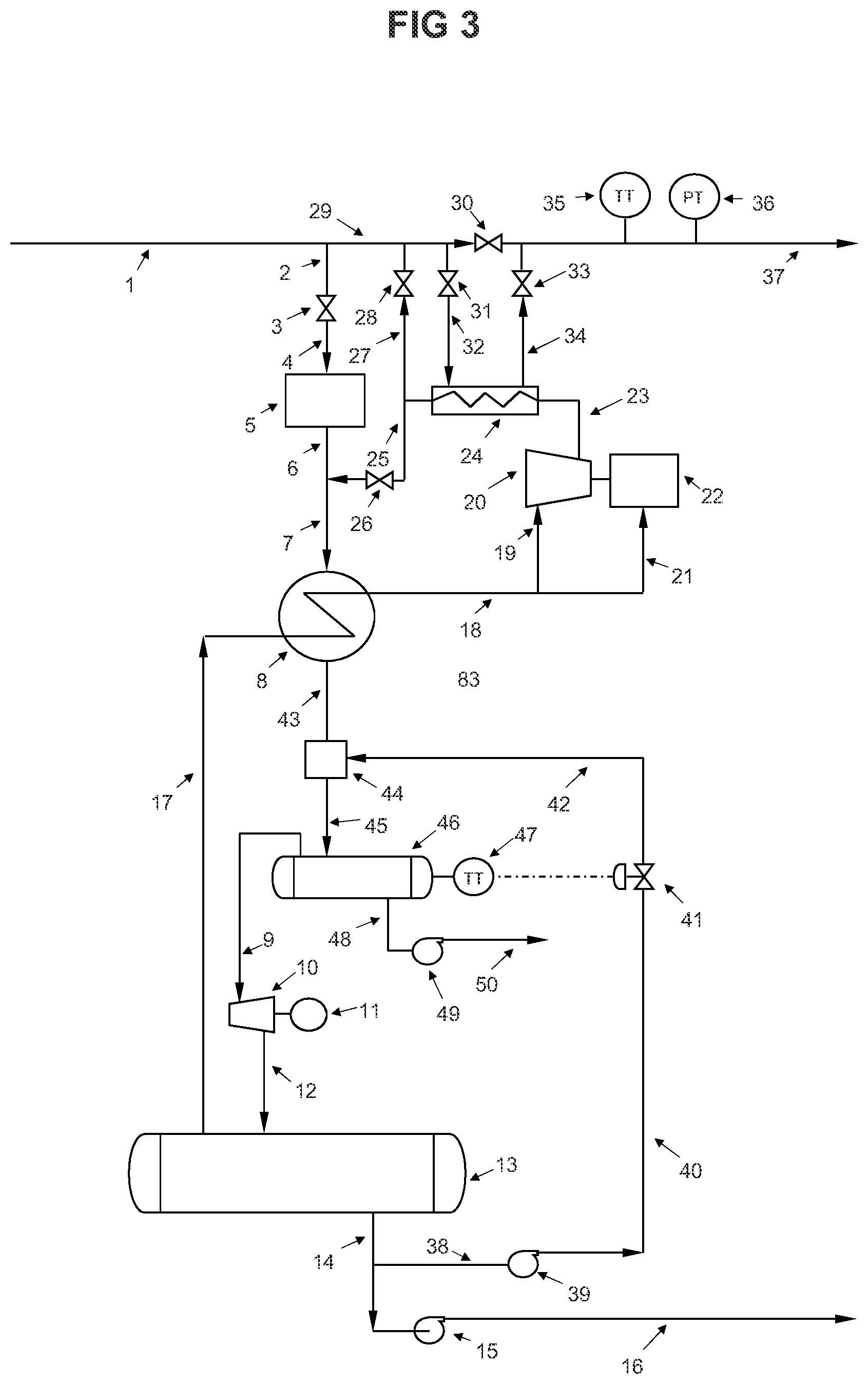
FIG. 3 is a schematic diagram of a facility equipped with the ability to recover natural gas liquids (NGLs).
DETAILED DESCRIPTION OF THE PREFERRED EMBODIMENT
The method will now be described with reference to FIG. 1.
As set forth above, this method was developed with a view to liquefying natural gas to form Liquid Natural Gas (LNG). The description of application of the method to LNG should, therefore, be considered as an example.
Referring to FIG. 1, a pressurized pipeline natural gas stream 1 provides natural gas to users through line 29, valve 30 to flow distribution 37. A natural gas stream 2 is routed through flow control valve 3. The controlled flow enters the gas pre-treatment unit 5 through line 4. Pre-treatment is to remove contaminants and may not be required if the gas used is of sufficient quality. The pre-treated gas exits through line 6 and is mixed with recycled gas stream 25 through valve 26. The mixed gas stream 7 enters heat exchanger 8 where it is pre-cooled. The pressurized pre-cooled gas stream 9 enters expander 10 where the pressure is dropped resulting in a substantial temperature drop. The nearly isentropic expansion also produces torque and therefore shaft power that is converted into electricity through generator 11. The expanded gas stream 12 enters LNG receiver 13 where the liquid and vapour fractions are separated. The vapour stream 17 is routed through heat exchanger 8 to pre-cool inlet gas stream 7. The now warmed gas stream 18 enters compressor 20 through line 19 for re-compression. The compressor 20 shaft power is provided by a gas engine 22 which receives its fuel from gas line 21. The compressed recycled gas stream 23 is cooled in heat exchanger 24 before mixing it with inlet feed gas stream 6 through line 25. To prevent a buildup of nitrogen in the recycle gas stream 25, a bleeding gas stream 27 is routed to gas transmission line 29 through valve 28. The cooling of compressed recycled gas stream 23 is provided by a once through heat exchange from gas transmission line 29. The required gas coolant is routed through valve 31 and line 32 into heat exchanger 24 and the once through flow is returned to gas transmission line 29 through line 34 and valve 33. The LNG receiver 13 accumulates the LNG produced. LNG exits receiver 13 through stream 14 to supply LNG product pump 15, where it is pumped to storage through line 16.
A main feature of this invention is the simplicity of the process which eliminates the use of external refrigeration systems. Another feature of the invention is the flexibility of the process to meet various operating conditions since the ratio of LNG production is proportional to the cold vapour stream generated and recycled. The invention also provides for a significant savings in energy when compared to other processes since it uses its recycled vapour stream as the coolant medium, the process produces its own refrigeration stream. The proposed invention can be used in any LNG production plant size.
Referring to FIG. 2, the main difference from FIG. 1 is in the heat exchanger to cool recycle stream 23. In FIG. 2, the heat exchanger 50 is an air cooling heat exchanger where ambient air is used to cool stream 23. This process orientation provides an alternative method to produce LNG at albeit less efficient than when using heat exchanger 24 as shown in FIG. 1. A pressurized pipeline natural gas stream 1 provides natural gas to users through line 29, valve 30 to flow distribution 37. A natural gas stream 2 is routed through flow control valve 3, and enters the gas pre-treatment unit 5 through line 4. The pre-treated gas exits through line 6 and is mixed with recycle gas stream 25 through valve 26. The mixed gas stream 7 enters heat exchanger 8 where it is pre-cooled. The pressurized pre-cooled gas stream 9 enters expander 10 where the pressure is dropped resulting in a substantial temperature drop. The nearly isentropic expansion also produces torque and therefore shaft power that is converted into electricity through generator 11. The expanded gas stream 12 enters LNG receiver 13 where the liquid and vapour fractions are separated. The vapour stream 17 is routed through heat exchanger 8 to pre-cool inlet gas stream 7. The now warmed gas stream 18 enters compressor 20 through line 19 for re-compression. The compressor 20 shaft power is provided by a gas engine 22 which receives its fuel from gas line 21. The compressed recycled gas stream 23 is cooled in heat exchanger 51 before mixing it with inlet feed gas stream 6 through line 25. To prevent a buildup of nitrogen in the recycle gas stream 25, a bleeding gas stream 27 is routed to gas transmission line 29 through valve 28. The cooling of compressed recycled gas stream 23 is provided by an air cooling heat exchanger 51. The LNG receiver 13 accumulates the LNG produced. LNG exits receiver 13 through stream 14 to supply LNG product pump 15, where it is pumped to storage through line 16.
Referring to FIG. 3, the main difference from FIGS. 1 and 2 is the recovery of natural gas liquids before expansion. This is achieved by circulating a portion of the generated liquid natural gas (LNG), stream 42 and mixing it in 43 with the pre-cooled gas stream 51 to meet the temperature required to condense the heavier fractions present in the natural gas stream such as; butane, propane and ethane. This process orientation provides an alternative method to produce both LNG and NGLs. A pressurized pipeline natural gas stream 1 provides natural gas to users through line 29, valve 30 to gas flow transmission line 37. A natural gas stream 2 is routed through flow control valve 3, and enters the gas pre-treatment unit 5 through line 4. The pre-treated gas exits through line 6 and is mixed with recycle gas stream 25 through valve 26, the mixed gas stream 7 enters heat exchanger 8 where it is pre-cooled. The pressurized pre-cooled gas stream 43 enters mixer 44, a LNG stream 42 is also added to mixer 44. The addition of LNG stream to mixer 44 is controlled by temperature control valve 41. The mixed stream 45, enters separator 46 where the NGLs are separated and accumulated. The NGLs exit separator 46 through line 47 to NGL pump 49 and pumped to storage through line 50. The pressurized, pre-cooled and de-liquified gas stream 9 enters expander 10 where the pressure is dropped resulting in a substantial temperature drop. The nearly isentropic expansion also produces torque and therefore shaft power that is converted into electricity through generator 11. The expanded gas stream 12 enters LNG receiver 13 where the liquid and vapour fractions are separated. The vapour stream 17 is routed through heat exchanger 8 to pre-cool inlet gas stream 7. The now warmed gas stream 18 enters compressor 20 through line 19 for re-compression. The compressor 20 shaft power is provided by a gas engine 22 which receives its fuel from gas line 21. The compressed recycled gas stream 23 is cooled in heat exchanger 24 before mixing it with inlet feed gas stream 6 through line 25 and valve 26. To prevent a buildup of nitrogen in the recycle gas stream 25, a bleeding gas stream 27 is routed to gas transmission line 29 through valve 28.
The cooling of compressed recycled gas stream 23 is provided by a once through heat exchange from gas transmission line 29. The required gas coolant is routed through valve 31 and line 32 into heat exchanger 24 and the once through flow is returned to gas transmission line 29 through line 34 and valve 33. The LNG receiver 13 accumulates the LNG produced. LNG exits receiver 13 through stream 14 to supply LNG product pump 15, where it is pumped to storage through line 16. A portion of the produced LNG is routed through line 38 to high pressure LNG pump 39. The pressurized LNG liquid stream is controlled by temperature valve 41 to a pre-set temperature through temperature transmitter 47. The controlled LNG stream 42 enters mixer 44 to cool and condense the desired natural gas liquids. The proposed invention addresses both large and small plants in which process simplicity and ease of operation are the main components. The invention eliminates the need for refrigeration cycle plants and the use of proprietary mixed refrigerants. By simplifying the process, it reduces capital, maintenance, and operations costs. In the preferred method, natural gas is first pre-cooled with produced cold vapor then expanded through a gas expander. The gas expander produces electricity. The expanded gas produces a vapour and a liquid stream. The vapour stream is recycled by first pre-cooling the feed gas to the expander and then recompressed, cooled and recycled. A portion of the produced LNG provides the cold energy required as a recycle stream to cool and liquefy the pre-treated natural gas stream to recover desired natural gas liquids. The proposed invention eliminates the practice and use of mixed refrigerant cycles resulting in lower capital and operating costs. The process is applicable to any LNG plant size.
VARIATIONS
It should be noted that the motive force for the compressor can be provided by an electric motor versus a gas driven engine as proposed. Moreover, the compressed vapour stream can be discharged into gas transmission line 29 rather than recycled as proposed.
In this patent document, the word "comprising" is used in its non-limiting sense to mean that items following the word are included, but items not specifically mentioned are not excluded. A reference to an element by the indefinite article "a" does not exclude the possibility that more than one of the element is present, unless the context clearly requires that there be one and only one of the elements.
The scope of the claims should not be limited by the preferred embodiments set forth in the examples, but should be given a broad purposive interpretation consistent with the description as a whole.
* * * * *
D00000
D00001
D00002
D00003
XML
uspto.report is an independent third-party trademark research tool that is not affiliated, endorsed, or sponsored by the United States Patent and Trademark Office (USPTO) or any other governmental organization. The information provided by uspto.report is based on publicly available data at the time of writing and is intended for informational purposes only.
While we strive to provide accurate and up-to-date information, we do not guarantee the accuracy, completeness, reliability, or suitability of the information displayed on this site. The use of this site is at your own risk. Any reliance you place on such information is therefore strictly at your own risk.
All official trademark data, including owner information, should be verified by visiting the official USPTO website at www.uspto.gov. This site is not intended to replace professional legal advice and should not be used as a substitute for consulting with a legal professional who is knowledgeable about trademark law.