Gas turbine engine with geared architecture
McCune , et al. Feb
U.S. patent number 10,570,855 [Application Number 16/166,235] was granted by the patent office on 2020-02-25 for gas turbine engine with geared architecture. This patent grant is currently assigned to UNITED TECHNOLOGIES CORPORATION. The grantee listed for this patent is United Technologies Corporation. Invention is credited to Michael E. McCune, Lawrence E. Portlock, Frederick M. Schwarz.


| United States Patent | 10,570,855 |
| McCune , et al. | February 25, 2020 |
Gas turbine engine with geared architecture
Abstract
A gas turbine engine according to an example of the present disclosure includes, among other things, a turbo fan shaft and a turbo fan supported on the fan shaft, a compressor section having compressor hubs with blades driven about an axis, and an epicyclic gear system driving the fan shaft. The gear system includes a carrier supporting intermediate gears that mesh with a sun gear, a ring gear surrounding and meshing with the intermediate gears, the ring gear including first and second portions each having an inner periphery with teeth, the first and second portions abutting one another at a radial interface, each of the first and second portions including a flange extending radially outward, and the first and second portions having grooves at the radial interface which form a hole that expels oil through the ring gear to a gutter, and an input shaft driving the fan shaft through the gear system, the input shaft connected to the sun gear.
| Inventors: | McCune; Michael E. (Colchester, CT), Portlock; Lawrence E. (Bethany, CT), Schwarz; Frederick M. (Glastonbury, CT) | ||||||||||
|---|---|---|---|---|---|---|---|---|---|---|---|
| Applicant: |
|
||||||||||
| Assignee: | UNITED TECHNOLOGIES CORPORATION
(Farmington, CT) |
||||||||||
| Family ID: | 54321604 | ||||||||||
| Appl. No.: | 16/166,235 | ||||||||||
| Filed: | October 22, 2018 |
Prior Publication Data
| Document Identifier | Publication Date | |
|---|---|---|
| US 20190113003 A1 | Apr 18, 2019 | |
Related U.S. Patent Documents
| Application Number | Filing Date | Patent Number | Issue Date | ||
|---|---|---|---|---|---|
| 14753048 | Jun 29, 2015 | 10107231 | |||
| 13346120 | Jan 9, 2012 | ||||
| 11504220 | Aug 15, 2006 | 8753243 | |||
| Current U.S. Class: | 1/1 |
| Current CPC Class: | F02C 7/36 (20130101); F02K 3/06 (20130101); F16H 57/04 (20130101); F16H 57/0479 (20130101); F05D 2260/40311 (20130101); F05D 2240/70 (20130101); F05D 2220/36 (20130101); F16H 57/0486 (20130101); F05D 2260/4031 (20130101); F05D 2260/34 (20130101); F05D 2220/323 (20130101) |
| Current International Class: | F16H 57/04 (20100101); F02K 3/06 (20060101); F02C 7/36 (20060101) |
References Cited [Referenced By]
U.S. Patent Documents
| 2258792 | April 1941 | New |
| 2288792 | July 1942 | Daniels |
| 2684591 | July 1954 | Lundquist |
| 2936655 | May 1960 | Peterson et al. |
| 3021731 | February 1962 | Stoeckicht |
| 3160026 | December 1964 | Rosen |
| 3194487 | July 1965 | Tyler et al. |
| 3287906 | November 1966 | McCormick |
| 3352178 | November 1967 | Lindgren et al. |
| 3412560 | November 1968 | Gaubatz |
| 3664612 | May 1972 | Skidmore et al. |
| 3722323 | March 1973 | Welch |
| 3747343 | July 1973 | Rosen |
| 3754484 | August 1973 | Roberts |
| 3820719 | June 1974 | Clark |
| 3892358 | July 1975 | Gisslen |
| 3932058 | January 1976 | Harner et al. |
| 3935558 | January 1976 | Miller et al. |
| 3988889 | November 1976 | Chamay et al. |
| 4130872 | December 1978 | Harloff |
| 4284174 | August 1981 | Salvana et al. |
| 4289360 | September 1981 | Zirin |
| 4478551 | October 1984 | Honeycutt, Jr. et al. |
| 4583413 | April 1986 | Lack |
| 4649114 | March 1987 | Miltenburger et al. |
| 4696156 | September 1987 | Burr et al. |
| 4896499 | January 1990 | Rice |
| 4979362 | December 1990 | Vershure, Jr. |
| 5081832 | January 1992 | Mowill |
| 5102379 | April 1992 | Pagluica et al. |
| 5141400 | August 1992 | Murphy et al. |
| 5211541 | May 1993 | Fledderjohn et al. |
| 5302031 | April 1994 | Yuasa |
| 5317877 | June 1994 | Stuart |
| 5361580 | November 1994 | Ciokajlo et al. |
| 5391125 | February 1995 | Turra et al. |
| 5433674 | July 1995 | Sheridan et al. |
| 5447411 | September 1995 | Curley et al. |
| 5466198 | November 1995 | McKibbin et al. |
| 5472383 | December 1995 | McKibbin |
| 5524847 | June 1996 | Brodell et al. |
| 5634767 | June 1997 | Dawson |
| 5677060 | October 1997 | Terentieva et al. |
| 5778659 | July 1998 | Duesler et al. |
| 5857836 | January 1999 | Stickler et al. |
| 5915917 | June 1999 | Eveker et al. |
| 5975841 | November 1999 | Lindemuth et al. |
| 5985470 | November 1999 | Spitsberg et al. |
| 6158210 | December 2000 | Orlando |
| 6223616 | May 2001 | Sheridan |
| 6315815 | November 2001 | Spadaccini et al. |
| 6318070 | November 2001 | Rey et al. |
| 6387456 | May 2002 | Eaton, Jr. et al. |
| 6402654 | June 2002 | Lanzon et al. |
| 6517341 | February 2003 | Brun et al. |
| 6530858 | March 2003 | Usoro et al. |
| 6607165 | August 2003 | Manteiga et al. |
| 6669597 | December 2003 | Usoro et al. |
| 6709492 | March 2004 | Spadaccini et al. |
| 6732502 | May 2004 | Seda |
| 6814541 | November 2004 | Evans et al. |
| 6883303 | April 2005 | Seda |
| 7021042 | April 2006 | Law |
| 7219490 | January 2007 | Dev |
| 7328580 | February 2008 | Lee et al. |
| 7374403 | May 2008 | Decker et al. |
| 7591754 | September 2009 | Duong et al. |
| 7632064 | December 2009 | Somanath |
| 7662059 | February 2010 | McCune |
| 7704178 | April 2010 | Sheridan et al. |
| 7806651 | October 2010 | Kennepohl et al. |
| 7824305 | November 2010 | Duong et al. |
| 7828682 | November 2010 | Smook |
| 7926260 | April 2011 | Sheridan et al. |
| 7950151 | May 2011 | Duong et al. |
| 7997868 | August 2011 | Liang et al. |
| 8074440 | December 2011 | Kohlenberg |
| 8205432 | June 2012 | Sheridan |
| 8894538 | November 2014 | McCune |
| 9752511 | September 2017 | McCune et al. |
| 2002/0064232 | May 2002 | Fukuhara et al. |
| 2002/0064327 | May 2002 | Toda et al. |
| 2004/0112041 | June 2004 | Law |
| 2005/0026745 | February 2005 | Mitrovic |
| 2006/0228206 | October 2006 | Decker et al. |
| 2007/0225111 | September 2007 | Duong et al. |
| 2008/0003096 | January 2008 | Kohli et al. |
| 2008/0006018 | January 2008 | Sheridan et al. |
| 2008/0044276 | February 2008 | McCune et al. |
| 2008/0096714 | April 2008 | McCune |
| 2008/0116009 | May 2008 | Sheridan et al. |
| 2008/0116010 | May 2008 | Portlock |
| 2008/0317588 | December 2008 | Grabowski et al. |
| 2009/0053058 | February 2009 | Kohlenberg et al. |
| 2009/0053606 | February 2009 | Kim et al. |
| 2009/0056306 | March 2009 | Suciu |
| 2009/0056343 | March 2009 | Suciu et al. |
| 2009/0081039 | March 2009 | McCune et al. |
| 2009/0090096 | April 2009 | Sheridan |
| 2009/0111639 | April 2009 | Klingels |
| 2009/0293278 | December 2009 | Duong et al. |
| 2009/0298640 | December 2009 | Duong et al. |
| 2009/0314881 | December 2009 | Suciu et al. |
| 2010/0105516 | April 2010 | Sheridan et al. |
| 2010/0148396 | June 2010 | Xie et al. |
| 2010/0212281 | August 2010 | Sheridan |
| 2010/0218483 | September 2010 | Smith |
| 2010/0331139 | December 2010 | McCune |
| 2011/0130246 | June 2011 | McCune |
| 2011/0159797 | June 2011 | Beltman et al. |
| 2011/0293423 | December 2011 | Bunker et al. |
| 2012/0124964 | May 2012 | Hasel et al. |
| 2012/0243971 | September 2012 | McCune et al. |
| 2012/0275904 | November 2012 | McCune et al. |
| 2013/0023378 | January 2013 | McCune et al. |
| 2014/0133958 | May 2014 | McCune et al. |
| 2014/0154054 | June 2014 | Sheridan et al. |
| 2014/0230403 | August 2014 | Merry et al. |
| 2015/0065285 | March 2015 | McCune et al. |
| 1952435 | Apr 2007 | CN | |||
| 0791383 | Aug 1997 | EP | |||
| 1114949 | Jul 2001 | EP | |||
| 1142850 | Oct 2001 | EP | |||
| 1876338 | Jan 2008 | EP | |||
| 1890054 | Feb 2008 | EP | |||
| 1925855 | May 2008 | EP | |||
| 2224100 | Sep 2010 | EP | |||
| 2559913 | Feb 2013 | EP | |||
| 2610463 | Jul 2013 | EP | |||
| 1357038 | Apr 1964 | FR | |||
| 1516041 | Jun 1978 | GB | |||
| 2041090 | Sep 1980 | GB | |||
| 2426792 | Dec 2006 | GB | |||
| 5248267 | Sep 1993 | JP | |||
| 9317833 | Dec 1997 | JP | |||
| 2001208146 | Aug 2001 | JP | |||
| 3920031 | May 2007 | JP | |||
| 4636927 | Feb 2011 | JP | |||
| 2015137649 | Jul 2015 | JP | |||
| 2007038674 | Apr 2007 | WO | |||
| 20130147951 | Oct 2013 | WO | |||
| 2015017041 | Feb 2015 | WO | |||
Other References
|
Winn, A. (Ed). (1990). Wide Chord Fan Club. Flight International, 4217(137). May 23-29, 1990. pp. 34-38. cited by applicant . Parker, R.G. and Lin, J. (2001). Modeling, modal properties, and mesh stiffness variation instabilities of planetary gears. Prepared for NASA. NASA/CR-2001-210939. May 2001. pp. 1-111. cited by applicant . Mancuso, J.R. and Corcoran, J.P. (2003). What are the differences in high performance flexible couplings for turbomachinery? Proceedings of the Thirty-Second Turbomachinery Symposium. 2003. pp. 189-207. cited by applicant . Dudley, D.W., Ed. (1954). Handbook of practical gear design. Lancaster, PA: Technomic Publishing Company, Inc. pp. 3.96-102 and 8.12-18. cited by applicant . Dudley, D.W., Ed. (1962). Gear handbook. New York, NY: McGraw-Hill. pp. 3.14-18 and 12.7-12.21. cited by applicant . Dudley, D.W., Ed. (1994). Practical gear design. New York, NY: McGraw-Hill. pp. 119-124. cited by applicant . Product Brochure. Garrett TFE731. Allied Signal. Copyright 1987. pp. 1-24. cited by applicant . Honeywell Learjet 31 and 35/36 TFE731-2 to 2C Engine Upgrade Program. Sep. 2005. pp. 1-4. cited by applicant . Honeywell Sabreliner 65 TFET31-3 to -3D Engine Upgrade Program. Oct. 2005. pp. 1-4. cited by applicant . Kurzke, J. (2012). GasTurb 12: Design and off-design performance of gas turbines. Retrieved from: https://www.scribd.com/document/153900429/GasTurb-12. cited by applicant . Ahmad, F. and Mizramoghadam, A.V. (1999). Single v. two stage high pressure turbine design of modern aero engines. ASME. Prestend at the International Gast Turbine & Aeroengine Congress & Exhibition. Indianapolis, Indiana. Jun. 7-10, 1999. pp. 1-9. cited by applicant . Riegler, C., and Bichlmaier, C. (2007). The geared turbofan technology--Opportunities, challenges and readiness status. Porceedings CEAS. Sep. 10-13, 2007. Berlin, Germany. pp. 1-12. cited by applicant . About GasTurb. Retrieved Jun. 26, 2018 from: http://gasturb.de/about-gasturb.html. cited by applicant . Kurzke, J. (2001). GasTurb 9: A porgram to calculate design and off-design performance of gas turbines. Retrieved from: https://www.scribd.com/document/92384867/GasTurb9Manual. cited by applicant . Tummers, B. (2006). DataThief III. Retreived from: https://datathief.org/DatathiefManual.pdf pp. 1-52. cited by applicant . Manual. Student's Guide to Learning SolidWorks Software. Dassault Systemes--SolidWorks Corporation. pp. 1-156. cited by applicant . Macisaac, B. and Langston, R. (2011). Gas turbine propulsion systems. Chichester, West Sussex: John Wiley & Sons, Ltd. pp. 260-265. cited by applicant . Datasheet. CFM56-5B for the Airbus A320ceo family and CFM56-7B for the Boeing 737 family. https://www.cfmaeroengines.com/. cited by applicant . Turner, M. G., Norris, A., and Veres, J.P. (2004). High-fidelity three-dimensional simulation of the GE90. NASA/TM-2004-212981. pp. 1-18. cited by applicant . Defeo, A. and Kulina, M. (1977). Quiet clean short-haul experimental engine (QCSEE) main reduction gears detailed design final report. Prepared for NASA. NASA-CR-134872. Jul. 1977. pp. 1-221. cited by applicant . Amezketa, M., Iriarte, X., Ros, J., and Pintor, J. (2009). Dynamic model of a helical gear pair with backlash and angle0varying mesh stiffness. Multibody Dynamics 2009, ECCOMAS Thematic Conference. 2009. pp. 1-36. cited by applicant . Singh, A. (2005). Application of a system level model to study the planetary load sharing behavior. Jounal of Mechanical Design. vol. 127. May 2005. pp. 469-476. cited by applicant . Smith-Boyd, L. and Pike, J. (1986). Expansion of epicyclic gear dynamic analysis program. Prepared for NASA. NASA CR-179563. Aug. 1986. pp. 1-98. cited by applicant . Wikipedia. Torsion spring. Retreived Jun. 29, 2018 from: https://en.wikipedia.org/wiki/Torsion_spring. cited by applicant . AGMA Standard (2006). Design manual for enclosed epicyclic gear drives. Alexandria, VA: American Gear Manufacturers Association. pp. 1-104. cited by applicant . AGMA Standard (1997). Design and selection of components for enclosed gear drives. lexandria, VA: American Gear Manufacturers Association. pp. 1-48. cited by applicant . Daly, M. Ed. (2007). Jane's Aero-Engine. Issue Twenty-three. Mar. 2008. p. 710-712. cited by applicant . AGMA Standard (1999). Flexible couplings--Mass elastic properties and other characteristics. Alexandria, VA: American Gear Manufacturers Association. pp. 1-46. cited by applicant . Wikipedia. Stiffness. Retrieved Jun. 28, 2018 from: https://en.wikipedia.org/wiki/Stiffness. cited by applicant . Damerau, J. (2014) What is the mesh stiffness of gears? Screen shot of query submitted by Vahid Dabbagh, answered by Dr. Jochan Damerau, Research General Manager at Bosch Corp., Japan. Retrieved from: https://www.researchgate.net/post/What_is_the_mesh_stiffness_of_gears. cited by applicant . Hill, P.G., Peterson, C.R. (1965). Mechanics and thermodynamics of propulsion. Addison-Wesley Publishing Company, Inc. pp. 307-308. cited by applicant . Hill, P.G., Peterson, C.R. (1992). Mechanics and thermodynamics of propulsion, 2nd Edition. Addison-Wesley Publishing Company, Inc. pp. 400-406. cited by applicant . Kasuba, R. and August, R. (1984). Gear mesh stiffness and load sharing in planetary gearing. American Society of Mechanical Engineers, Design Engineering Technical Conference, Cambridge, MA. Oct. 7-10, 1984. pp. 1-6. cited by applicant . Ciepluch, C. (1977). Quiet clean short-haul experimental engine (QCSEE) under-the-wing (UTW) final design report. Prepared for NASA. NASA-CP-134847. Retreived from: https://ntrs.nasa.gov/archive/nasa/casi.ntrs.nasa.gov/19800075257.pdf. cited by applicant . Mcmillian, A. (2008) Material development for fan blade containment casing. Abstract. p. 1. Conference on Engineering and Physics: Synergy for Success 2006. Journal of Physics: Conference Series vol. 105. London, UK. Oct. 5, 2006. cited by applicant . Kurzke, J. (2009). Fundamental differences between conventional and geared turbofans. Proceedings of ASME Turbo Expo: Power for Land, Sea, and Air. 2009, Orlando, Florida. pp. 145-153. cited by applicant . Agarwal, B.D and Broutman, L.J. (1990). Analysis and performance of fiber composites, 2nd Edition. John Wiley & Sons, Inc. New York: New York. pp. 1-30, 50-51, 56-58, 60-61, 64-71, 87-89, 324-329, 436-437. cited by applicant . Carney, K., Pereira, M. Revilock, and Matheny, P. (2003). Jet engine fan blade containment using two alternate geometries. 4th European LS-DYNA Users Conference. pp. 1-10. cited by applicant . Brines, G.L. (1990). The turbofan of tomorrow. Mechanical Engineering: The Journal of the American Society of Mechanical Engineers,108(8), 65-67. cited by applicant . Faghri, A. (1995). Heat pipe and science technology. Washington, D.C.: Taylor & Francis. pp. 1-60. cited by applicant . Hess, C. (1998). Pratt & Whitney develops geared turbofan. Flug Revue 43(7). Oct. 1998. cited by applicant . Grady, J.E., Weir, D.S., Lamoureux, M.C., and Martinez, M.M. (2007). Engine noise research in NASA's quiet aircraft technology project. Papers from the International Symposium on Air Breathing Engines (ISABE). 2007. cited by applicant . Griffiths, B. (2005). Composite fan blade containment case. Modern Machine Shop. Retrieved from: http://www.mmsonline.com/articles/composite-fan-blade-containment-case pp. 1-4. cited by applicant . Hall, C.A. and Crichton, D. (2007). Engine design studies for a silent aircraft. Journal of Turbomachinery, 129, 479-487. cited by applicant . Haque, A. and Shamsuzzoha, M., Hussain, F., and Dean, D. (2003). S20-glass/epoxy polymer nanocomposites: Manufacturing, structures, thermal and mechanical properties. Journal of Composite Materials, 37(20), 1821-1837. cited by applicant . Brennan, P.J. and Kroliczek, E.J. (1979). Heat pipe design handbook. Prepared for National Aeronautics and Space Administration by B & K Engineering, Inc. Jun. 1979. pp. 1-348. cited by applicant . Horikoshi, S. and Serpone, N. (2013). Introduction to nanoparticles. Microwaves in nanoparticle synthesis. Wiley-VCH Verlag GmbH & Co. KGaA. pp. 1-24. cited by applicant . Kerrebrock, J.L. (1977). Aircraft engines and gas turbines. Cambridge, MA: The MIT Press. p. 11. cited by applicant . Xie, M. (2008). Intelligent engine systems: Smart case system. NASA/CR-2008-215233. pp. 1-31. cited by applicant . Knip, Jr., G. (1987). Analysis of an advanced technology subsonic turbofan incorporating revolutionary materials. NASA Technical Memorandum. May 1987. pp. 1-23. cited by applicant . Willis, W.S. (1979). Quiet clean short-haul experimental engine (QCSEE) final report NASA/CR-159473 pp. 1-289. cited by applicant . Kojima, Y., Usuki, A. Kawasumi, M., Okada, A., Fukushim, Y., Kurauchi, T., and Kamigaito, O. (1992). Mechanical properties of nylon 6-clay hybrid. Journal of Materials Research, 8(5), 1185-1189. cited by applicant . Kollar, L.P. and Springer, G.S. (2003). Mechanics of composite structures. Cambridge, UK: Cambridge University Press. p. 465. cited by applicant . Ramsden, J.M. (Ed). (1978). The new European airliner. Flight International, 113(3590). Jan. 7, 1978. pp. 39-43. cited by applicant . Langston, L. and Faghri, A. Heat pipe turbine vane cooling. Prepared for Advanced Turbine Systems Annual Program Review. Morgantown, West Virginia. Oct. 17-19, 1995. pp. 3-9. cited by applicant . Oates, G.C. (Ed). (1989). Aircraft propulsion systems and technology and design. Washington, D.C.: American Institute of Aeronautics, Inc. pp. 341-344. cited by applicant . Lau, K., Gu, C., and Hui, D. (2005). A critical review on nanotube and nanotube/nanoclay related polymer composite materials. Composites: Part B 37(2006) 425-436. cited by applicant . Shorter Oxford English dictionary, 6th Edition. (2007). vol. 2, N-Z. p. 1888. cited by applicant . Lynwander, P. (1983). Gear drive systems: Design and application. New York, New York: Marcel Dekker, Inc. pp. 145, 355-358. cited by applicant . Sweetman, B. and Sutton, O. (1998). Pratt & Whitney's surprise leap. Interavia Business & Technology, 53.621, p. 25. cited by applicant . Mattingly, J.D. (1996). Elements of gas turbine propulsion. New York, New York: McGraw-Hill, Inc. pp. 8-15. cited by applicant . Pyrograf-III Carbon Nanofiber. Product guide. Retrieved Dec. 1, 2015 from: http://pyrografproducts.com/Merchant5/merchant.mvc?Screen=cp_nanofiber. cited by applicant . Nanocor Technical Data for Epoxy Nanocomposites using Nanomer 1.30E Nanoclay. Nnacor, Inc. Oct. 2004. cited by applicant . Ratna, D. (2009). Handbook of thermoset resins. Shawbury, UK: iSmithers. pp. 187-216. cited by applicant . Wendus, B.E., Stark, D.F., Holler, R.P., and Funkhouser, M.E. (2003). Follow-on technology requirement study for advanced subsonic transport. NASA/CR-2003-212467. pp. 1-37. cited by applicant . Silverstein, C.C., Gottschlich, J.M., and Meininger, M. The feasibility of heat pipe turbine vane cooling. Presented at the International Gas Turbine and Aeroengine Congress and Exposition, The Hague, Netherlands. Jun. 13-16, 1994.pp. 1-7. cited by applicant . Merriam-Webster's collegiate dictionary, 11th Ed. (2009). p. 824. cited by applicant . Merriam-Webster's collegiate dictionary, 10th Ed. (2001). p. 1125-1126. cited by applicant . Whitaker, R. (1982). ALF 502: plugging the turbofan gap. Flight International, p. 237-241, Jan. 30, 1982. cited by applicant . Hughes, C. (2010). Geared turbofan technology. NASA Environmentally Responsible Aviation Project. Green Aviation Summit. NASA Ames Research Center. Sep. 8-9, 2010. pp. 1-8. cited by applicant . Gliebe, P.R. and Janardan, B.A. (2003). Ultra-high bypass engine aeroacoustic study. NASA/CR-2003-21252. GE Aircraft Engines, Cincinnati, Ohio. Oct. 2003. pp. 1-103. cited by applicant . Moxon, J. How to save fuel in tomorrow's engines. Flight International. Jul. 30, 1983. 3873(124). pp. 272-273. cited by applicant . File History for U.S. Appl. No. 12/131,876. cited by applicant . Cusick, M. (1981). Avco Lycoming's ALF 502 high bypass fan engine. Society of Automotive Engineers, inc. Business Aircraft Meeting & Exposition. Wichita, Kansas. Apr. 7-10, 1981. pp. 1-9. cited by applicant . Fledderjohn, K.R. (1983). The TFE731-5: Evolution of a decade of business jet service. SAE Technical Paper Series. Business Aircraft Meeting & Exposition. Wichita, Kansas. Apr. 12-15, 1983. pp. 1-12. cited by applicant . Dickey, T.A. and Dobak, E.R. (1972). The evolution and development status of ALF 502 turbofan engine. National Aerospace Engineering and Manufacturing Meeting. San Diego, California. Oct. 2-5, 1972. pp. 1-12. cited by applicant . Gunston, B. (Ed.) (2000). Jane's aero-engines, Issue seven. Coulsdon, Surrey, UK: Jane's Information Group Limited. pp. 510-512. cited by applicant . Ivchenko-Progress D-436. Jane's Aero-engines, Aero-engines--Turbofan. Feb. 8, 2012. cited by applicant . Ivchenko-Progress AI-727M. Jane's Aero-engines, Aero-engines--Turbofan. Nov. 27, 2011. cited by applicant . Ivchenko-Progress D-727. Jane's Aero-engines, Aero-engines--Turbofan. Feb. 7, 2007. cited by applicant . Turbomeca Aubisque. Jane's Aero-engines, Aero-engines--Turbofan. Nov. 2, 2009. cited by applicant . Aviadvigatel D-110. Jane's Aero-engines, Aero-engines--Turbofan. Jun. 1, 2010. cited by applicant . Rolls-Royce M45H. Jane's Aero-engines, Aero-engines--Turbofan. Feb. 24, 2010. cited by applicant . Honeywell LF502. Jane's Aero-engines, Aero-engines--Turbofan. Feb. 9, 2012. cited by applicant . Honeywell LF507. Jane's Aero-engines, Aero-engines--Turbofan. Feb. 9, 2012. cited by applicant . Honeywell TFE731. Jane's Aero-engines, Aero-engines--Turbofan. Jul. 18, 2012. cited by applicant . NASA Conference Publication. Quiet, powered-lift propulsion. Cleveland, Ohio. Nov. 14-15, 1978. pp. 1-420. cited by applicant . "Civil Turbojet/Turbofan Specifications", Jet Engine Specification Database (Apr. 3, 2005). cited by applicant . Kandebo, S.W. (1993). Geared-turbofan engine design targets cost, complexity. Aviation Week & Space Technology, 148(8). Start p. 32. cited by applicant . Hendricks, E.S. and Tong, M.T. (2012). Performance and weight estimates for an advanced open rotor engine. NASA/TM-2012-217710. pp. 1-13. cited by applicant . Guynn, M. D., Berton, J.J., Fisher, K. L., Haller, W.J., Tong, M. T., and Thurman, D.R. (2011). Refined exploration of turbofan design options for an advanced single-aisle transport. NASA/TM-2011-216883. pp. 1-27. cited by applicant . Zalud, T. (1998). Gears put a new spin on turbofan performance. Machine Design, 70(20), p. 104. cited by applicant . Kurzke, J. (2008). Preliminary Design, Aero-engine design: From state of the art turbofans towards innovative architectures. pp. 1-72. cited by applicant . Zamboni, G. and Xu, L. (2009). Fan root aerodynamics for large bypass gas turbine engines: Influence on the engine performance and 3D design. Proceedings of ASME Turbo Expo 2009: Power for Land, Sea and Air. Jun. 8-12, 2009, Orlando, Florida, USA. pp. 1-12. cited by applicant . Han, J., Dutta, S., and Ekkad, S.V. (2000). Gas turbine heat transfer and cooling technology. New York, NY: Taylor & Francis. pp. 1-25, 129-157, and 160-249. cited by applicant . Mattingly, J.D. (1996). Elements of gas turbine propulsion. New York, New York: McGraw-Hill, Inc. pp. 1-18, 60-62, 85-87, 95-104, 121-123, 223-234, 242-245, 278-280, 303-309, 323-326, 462-479, 517-520, 563-565, 673-675, 682-685, 697-699, 703-705, 802-805, 862-864, and 923-925. cited by applicant . Declaration of Reza Abhari, Ph.D. In re U.S. Pat. No. 8,844,265. Executed Jun. 28, 2016. pp. 1-91. cited by applicant . Declaration of John Eaton, Ph.D. In re U.S. Pat. No. 8,869,568. Executed Mar. 28, 2016. pp. 1-87. cited by applicant . Declaration of Reza Abhari. In re U.S. Pat. No. 8,695,920. Executed Nov. 30. pp. 1-67. cited by applicant . Declaration of Reza Abhari. In re U.S. Pat. No. 8,448,895. Executed Nov. 28. pp. 1-81. cited by applicant . Declaration of Reza Abhari. In re U.S. Pat. No. 8,695,920, claims 1-4, 7-14, 17 and 19. Executed Nov. 29. pp. 1-102. cited by applicant . Declaration of Dr. Magdy Attia. In re U.S. Pat. No. 8,313,280. Executed Oct. 21, 2016. pp. 1-88. cited by applicant . Lord, W.K., Macmartin, D.G., and Tillman, T.G. (2000). Flow control opportunities in gas turbine engines. American Institute of Aeronautics and Astronautics. pp. 1-15. cited by applicant . Daly, M. Ed. (2010). Jane's Aero-Engine. Issue Twenty-seven. Mar. 2010. p. 633-636. cited by applicant . Roux, E. (2007). Turbofan and turbojet engines database handbook. Editions Elodie Roux. Blagnac: France. pp. 1-595. cited by applicant . Wilfert, G. (2008). Geared fan. Aero-Engine Design: From State of the Art Turbofans Towards Innovative Architectures, von Karman Institute for Fluid Dynamics, Belgium, Mar. 3-7, 2008. pp. 1-26. cited by applicant . Declaration of Dr. Magdy Attia. In re U.S. Pat. No. 8,517,668. Executed Dec. 8, 2016. pp. 1-81. cited by applicant . Cramoisi, G. Ed. (2012). Death in the Potomac: The crash of Air Florida Flight 90. Air Crash Investigations. Accident Report NTSB/AAR-82-8. p. 45-47. cited by applicant . Norton, M. and Karczub, D. (2003). Fundamentals of noise and vibration analysis for engineers. Press Syndicate of the University of Cambridge. New York: New York. p. 524. cited by applicant . U.S. Department of Transportation: Federal Aviation Administration Advisory Circular. Runway overrun prevention. Dated: Nov. 6, 2007. p. 1-8 and Appendix 1 p. 1-15, Appendix 2 p. 1-6, Appendix 3 p. 1-3, and Appendix 4 p. 1-5. cited by applicant . U.S. Department of Transportation: Federal Aviation Administration Advisory Circular. Standard operating procedures for flight deck crewmembers. Dated: Feb. 27, 2003.. p. 1-6 and Appendices. cited by applicant . Vasudevan, A.K. and Petrovic, J.J. (1992). A comparative overview of molybedenum disilicide composites. Materials Science and Engineering, A155, 1992. pp. 1-17. cited by applicant . Clarke, D.R. and Levi, C.G. (2003). Materials design for the next generation thermal barrier coatings. Annual. Rev. Mater. Res. vol. 33. 2003. pp. 383-417. cited by applicant . Lee, K.N. (2000). Current status of environmental barrier coatings for Si-Based ceramics. Surface and Coatings Technology 133-134, 2000. pp. 1-7. cited by applicant . Bornstein, N. (1993). Oxidation of advanced intermetallic compounds. Journal de Physique IV, 1993, 03 (C9), pp. C9-367-C9-373. cited by applicant . Krenkel, W., Naslain, R., and Schneider, H. Eds. (2001). High temperature ceramic matrix composites pp. 224-229. Weinheim, DE: Wiley-VCH Verlag GmbH. cited by applicant . Gibala, R., Ghosh, A.K., Van Aken, D.C., Srolovitz, D.J., Basu, A., Chang, H., . . . Yang, W. (1992). Mechanical behavior and interface design of MoSi2-based alloys and composites. Materials Science and Engineering, A155, 1992. pp. 147-158. cited by applicant . Shah, D.M. (1992). MoSi2 and other silicides as high temperature structural materials. Superalloys 1992. The Minerals, Metals, & Materials Society. pp. 409-422. cited by applicant . Zhao, J.C. and Westbrook, J.H. (2003). Ultrahigh-temperature materials for jet engines. MRS Bulletin. vol. 28(9). Sep. 2003. pp. 622-630. cited by applicant . Tsirlin, M., Pronin, Y.E., Florina, E.K., Mukhametov, S. Kh., Khatsernov, M.A., Yun, H.M., . . . Kroke, E. (2001). Experimental investigation of multifunctional interphase coatings on SiC fibers for non-oxide high temperature resistant CMCs. High Temperature Ceramic Matrix Composites. 4th Int'l Conf. on High Temp. Ceramic Matrix Composites. Oct. 1-3, 2001. pp. 149-156. cited by applicant . Jacobson, N.S. (1993). Corrosion of silicon-based ceramics in combustion environments. J. Am. Ceram. Soc. 76(1). pp. 3-28. cited by applicant . Jorgensen, P.J., Wadsworth, M.E., and Cutler, I.B. (1961). Effects of water vapor on oxidation of silicon carbide. J. Am. Ceram. Soc. 44(6). pp. 248-261. cited by applicant . Xu, Y., Cheng, L., Zhang, L., Ying, H., and Zhou, W. (1999). Oxidation behavior and mechanical properties of C/SiC composites with Si--MoSi2 oxidation protection coating. J. of Mat. Sci. vol. 34. 1999. pp. 6009-6014. cited by applicant . Sundaram, S.K., Hsu, J-Y., Speyer, R.F. (1995). Molten glass corrosion resistance of immersed combustion-heating tube materials in e-glass. J. Am. Ceram. Soc. 78(7). pp. 1940-1946. cited by applicant . Jeng, Y.-L., Lavernia, E.J. (1994). Processing of molybdenum disilicide. J. of Mat. Sci. vol. 29. 1994. pp. 2557-2571. cited by applicant . Suzuki, Y., Morgan, P.E.D., and Niihara, K. (1998). Improvement in mechanical properties of powder-processed MoSi2 by the addition of Sc2O3 and Y2O3. J. Am. Ceram. Soci. 81(12). pp. 3141-3149. cited by applicant . Webster, J.D., Westwood, M.E., Hayes, F.H., Day, R.J., Taylor, R., Duran, A., . . . Vogel, W.D. (1998). Oxidation protection coatings for C/SiC based on yttrium silicate. Journal of European Ceramic Society vol. 18. 1998. pp. 2345-2350. cited by applicant . Petrovic, J.J., Castro, R.G., Vaidya, R.U., Peters, M.I., Mendoza, D., Hoover, R.C., and Gallegos, D.E. (2001). Molybdenum disilicide materials for glass melting sensor sheaths. Ceramic Engineering and Science roceedings. vol. 22(3). 2001. pp. 59-64. cited by applicant . Kahn, H., Tayebi, N., Ballarini, R., Mullen, R.L., Heuer, A.H. (2000). Fracture toughness of polysilicon MEMS devices. Sensors and Actuators vol. 82. 2000. pp. 274-280. cited by applicant . Muhlstein, C.L., Stach, E.A., and Ritchie, R.O. (2002). A reaction-layer mechanism for the delayed failure of micron-scale polycrystalline silicon structural films subjected to high-cycle fatigue loading. Acta Materialia vol. 50. 2002. pp. 3579-3595. cited by applicant . Sundaram, S.K., Hsu, J-Y., Speyer, R.F. (1994). Molten glass corrosion resistance of immersed combustion-heating tube materials in soda-lime-silicate glass. J. Am. Ceram. Soc. 77(6). pp. 1613-1623. cited by applicant . Leckie, F.A. and Dal Bello, D.J. (2009). Strength and stiffness of engineering systems. Mechanical Engineering Series. Springer. pp. 1-3. cited by applicant . El-Sayad, A.F. (2008). Aircraft propulsion and gas turbine engines. Boca Raton, FL: CRC Press. pp. 215-219 and 855-860. cited by applicant . Bunker, R.S. (2005). A review of shaped hole turbine film-cooling technology. Journal of Heat Transfer vol. 127. Apr. 2005. pp. 441-453. cited by applicant . European Search Report for European Patent Application No. 18203501.4, completed Feb. 11, 2019. cited by applicant . The International Preliminary Report on Patentability for PCT Application No. PCT/US2012/071906, dated Jul. 24, 2014. cited by applicant . Meier, N (2005). Civil Turbojet/Turbofan Specifications. Retrieved from http://www.jet-engine.net/civtfspec.html. cited by applicant . European Search Report for European Patent Application No. 12198136.9 completed Aug. 21, 2013. cited by applicant . International Search Report and Written Opinion for International Application No. PCT/US2012/071906 completed on Aug. 22, 2013. cited by applicant . Japanese Office Action for Japanese Application No. 2007-202444 dated Aug. 3, 2010. cited by applicant . European Search Report for European Patent Application No. 07253078.5 completed Nov. 22, 2007. cited by applicant . European Search Report for European Patent Application No. 12198045.2 completed Sep. 7, 2015. cited by applicant . Decision Institution of Inter Partes Review. General Electric Company., Petitioner, v. United Technologies Corp., Patent Owner. IPR2017-01001. U.S. Pat. No. 8,894,538. Entered Jul. 10, 2017. pp. 1-4. cited by applicant . European Search Report for European Application No. 16183877.6 completed Dec. 23, 2016. cited by applicant . Petition for Inter Partes Review of U.S. Pat. No. 8,894,538. General Electric Company, Petitioner, v. United Technologies Corporation, Patent Owner. Filed Mar. 1, 2017. cited by applicant . European Search Report for European Application No. 16174068.3 completed Nov. 15, 2016. cited by applicant . Extended European Search Report for European Application No. 16171476.completed Sep. 28, 2016. cited by applicant . Dudley, "Gear Handbook: The Design, Manufacture, and Application of Gears", McGraw-Hill, Inc., 1962, pp. 3-14 and 3-15. cited by applicant . Kandebo; Geared-Turbofan Engine Design Targets Cost, Complexity, Aviation Week & Space Technology; New York; Feb. 23, 1998, 4 pp pp. 32-34. cited by applicant . Zalud, "Gears Put a New Spin on Turbofan Performance" Machine Design, Nov. 5, 1998, 2010Penton Media, Inc., 5 pp pp. 1-4. cited by applicant . Nanocor Technical Data for Epoxy Nanocomposites using Nanomer 1.30E Nanoclay. Nnacor, Inc. cited by applicant . NASA Conference Publication. Quiet, powered-lift propulsion. Cleveland, Ohio. Nov. 14-15, 1978. cited by applicant . Notice of Opposition to U.S. Pat. No. 2,610,463. United Technologies Corporation opposed by Safran Aircraft Engines. Mailed Aug. 3, 2016. cited by applicant . Munt, R. (1981). Aircraft technology assessment: Progress in low emissions engine. Technical Report. May 1981. pp. 1-171. cited by applicant . Avco Lycoming Divison. ALF 502L Maintenance Manual. Apr. 1981. pp. 1-118. cited by applicant . Type Certificate Data Sheet No. E6NE. Department of Transportation Federal Aviation Administration. Jun. 7, 2002. pp. 1-10. cited by applicant . Honeywell LF502. Jane's Aero-engines, Aero-engines--Turbofan. Aug. 17, 2016. cited by applicant . Rauch, D. (1972). Design study of an air pump and integral lift engine ALF-504 using the Lycoming 502 core. Prepare for NASA. Jul. 1972. pp. 1-182. cited by applicant . Dassault Falcon 900EX Easy Systems Summary. Retrieved from: http://www.smartcockpit.com/docs/F900EX-Engines.pdf pp. 1-31. cited by applicant . Honeywell TFE731 Pilot Tips. pp. 1-143. cited by applicant . Honeywell TFE731-5AR to -5BR Engine Conversion Program. Sep. 2005. pp. 1-4. cited by applicant . Garret TFE731 Turbofan Engine (CAT C). Chapter 79: Lubrciation System. TTFE731 Issue 2. 2010. pp. 1-24. cited by applicant . International Preliminary Report on Patentability for PCT Application No. PCT/US2013/023356 dated Aug. 14, 2014. cited by applicant . Davies, D. and Miller, D.C. (1971). A variable pitch fan for an ultra quiet demonstrator engine. 1976 Spring Convention: Seeds for Success in Civil Aircraft Design in the Next Two Decades. pp. 1-18. cited by applicant . Middleton, P. (1971). 614: VFW's jet feederliner. Flight International, Nov. 4, 1971. p. 725, 729-732. cited by applicant . Schaefer, J.W., Sagerser, D.R., and Stakolich, E.G. (1977). Dynamics of high-bypass-engine thrust reversal using a variable-pitch fan. Technical Report prepare for NASA. NASA-TM-X-3524. May 1, 1977. pp. 1-33. cited by applicant . Savelle, S.A. and Garrard, G.D. (1996). Application of transient and dynamic simulations to the U.S. Army T55-L-712 helicopter engine. The American Society of Mechanical Engineers. Presented Jun. 10-13, 1996. pp. 1-8. cited by applicant . Drago, R.J. and Margasahayam, R.N. (1987). Stress analysis of planet gears with integral bearings; 3D finite-element model development and test validation. 1987 MSC NASTRAN World Users Conference. Los Angeles, CA. Mar. 1987. pp. 1-14. cited by applicant . Baker, R.W. (2000). Membrane technology and applications. New York, NY: McGraw-Hill. pp. 87-151. cited by applicant . Cheryan, M. (1998). Ultrafiltration and microfiltration handbook. Lancaster, PA: Tecnomic Publishing Company, Inc. pp. 171-236. cited by applicant . Seader, J.D. and Henley, E.J. (1998). Separation process principles. New York, NY: John Wiley & Sons, Inc. pp. 722-726 and 764-771. cited by applicant . Spadaccini, L.J., and Huang, H. (2002). On-line fuel deoxygenation for coke suppression. ASME, Jun. 2002. pp. 1-7. cited by applicant . Darrah, S. (1987). Jet fuel deoxygenation. Interim Report for Period Mar. 1987-Jul. 1988. pp. 1-22. cited by applicant . Bucknell, R.L. (1973). Influence of fuels and lubricants on turbine engine design and performance, fuel and lubricant analyses. Final Technical Report, Mar. 1971-Mar. 1973. pp. 1-252. cited by applicant . Hazlett, R.N. (1991). Thermal oxidation stability of aviation turbine fuels. Philadelphia, PA: ASTM. pp. 1-163. cited by applicant . Taylor, W.F. (1974). Deposit formation from deoxygenated hydrocarbons. I. General features. Ind. Eng. Chem., Prod. Res. Develop., vol. 13(2). 1974. pp. 133-138. cited by applicant . Taylor, W.F. (1974). Deposit formation from deoxygenated hydrocarbons. II. Effect of trace sulfur compounds. Ind. Eng. Chem., Prod. Res. Dev., vol. 15(1). 1974. pp. 64-68. cited by applicant . Taylor, W.F. and Frankenfeld, J.W. (1978). Deposit fromation from deoxygenated hydrocarbons. 3. Effects of trace nitrogen and oxygen compounds. Ind. Eng. Chem., Prod. Res. Dev., vol. 17(1). 1978. pp. 86-90. cited by applicant . Frankenfeld, J.W. And Taylor, W.F. (1980). Deposit fromation from deoxygenated hydrocarbons. 4. Studies in pure compound systems. Ind. Eng. Chem., Prod. Res. Dev., vol. 19(1). 1978. pp. 65-70. cited by applicant . Hemighaus, G., Boval, T., Bacha, J., Barnes, F., Franklin, M., Gibbs, L., . . . Morris, J. (2007). Aviation fuels: Technical review. Chevron Products Company. pp. 1-94. Retrieved from: https://www.cgabusinessdesk.com/document/aviation_tech_review.pdf. cited by applicant . Spadaccini, L.J., Sobel, D.R., and Huang, H. (2001). Deposit formation and mitigation in aircraft fuels. Journal of Eng. For Gas Turbine and Power, vol. 123. Oct. 2001. pp. 741-746. cited by applicant . Edwards, T. and Zabarnick, S. (1993). Supercritical fuel deposition mechanisms. Ind. Eng. Chem. Res. vol. 32. 1993. pp. 3117-3122. cited by applicant . Huang, H., Sobel, D.R., and Spadaccini, L.J. (2002). Endothermic heat-sink of hydrocarbon fuels for scramjet cooling. AIAA/ASME/SAE/ASEE, Jul. 2002. pp. 1-7. cited by applicant . Bessarabov, D.G., Jacobs, E.P., Sanderson, R.D., and Beckman, I.N. (1996). Use of nonporous polymeric flat-sheet gas-separation membranes in a membrane-liquid contactor: experimental studies. Journal of Membrane Sciences, vol. 113. 1996. pp. 275-284. cited by applicant . Matsumoto, T., Toshiro, U., Kishida, A., Tsutomu, F., Maruyama, I., and Akashi, M. (1996). Novel functional polymers: Poly (dimethylsiloxane)-polyamide multiblock copolymer. VII. Oxygen permeability of aramid-silicone membranes in a gas-membrane-liquid system. Journal of Applied Polymer Science, vol. 64(6). May 9, 1997. pp. 1153-1159. cited by applicant . Technical Data. Teflon. WS Hampshire Inc. Retrieved from: http://catalog.wshampshire.com/Asset/psg_teflon_ptfe.pdf. cited by applicant . Anderson, N.E., Loewenthal, S.H., and Black, J.D. (1984). An analytical method to predict efficiency of aircraft gearboxes. NASA Technical Memorandum prepared for the Twentieth Joint Propulsion Conference. Cincinnati, OH. Jun. 11-13, 1984. pp. 1-25. cited by applicant . Edkins, D.P., Hirschkron, R., and Lee, R. (1972). TF34 turbofan quiet engine study. Final Report prepared for NASA. NASA-CR-120914. Jan. 1, 1972. pp. 1-99. cited by applicant . Waters, M.N. and Schairer, E.T. (1977). Analysis of turbofan propulsion system weight and dimensions. NASA Technical Memorandum. Jan. 1977. pp. 1-65. cited by applicant . Meyer, A.G. (1988). Transmission development of TEXTRON Lycoming's geared fan engine. Technical Paper. Oct. 1988. pp. 1-12. cited by applicant . Dudley, D.W., Ed. (1962). Gear handbook. New York, NY: McGraw-Hill. pp. 14-17 (TOC, Preface, and Index). cited by applicant . Hughes, C. (2002). Aerodynamic performance of scale-model turbofan outlet guide vanes designed for low noise. Prepared for the 40th Aerospace Sciences Meeting and Exhibit. Reno, NV. NASA/TM-2001-211352. Jan. 14-17, 2002. pp. 1-38. cited by applicant . Kaplan, B., Nicke, E., Voss, C. (2006), Design of a highly efficient low-noise fan for ultra-high bypass engines. Proceedings of GT2006 for ASME Turbo Expo 2006: Power for Land, Sea and Air. Barcelona, SP. May 8-11, 2006. pp. 1-10. cited by applicant . Gates, D. Bombardier flies at higher market. Seattle Times. Jul. 13, 2008. pp. C6. cited by applicant . Decker, S. and Clough, R. (2016). GE wins shot at voiding pratt patent in jet-engine clash. Bloomberg Technology. Retrieved from: https://www.bloomberg.com/news/articles/2016-06-30/ge-wins-shot-to-invali- date-pratt-airplane-engine-patent-in-u-s. cited by applicant . Trembley, Jr., H.F. (1977). Determination of effects of ambient conditions on aircraft engine emissions. ALF 502 combustor rig testing and engine verification test. Prepared for Environmental Protection Agency. Sep. 1977. pp. 1-256. cited by applicant . Lewicki, D.G., Black, J.D., Savage, M., and Coy, J.J. (1985). Fatigue life analysis of a turboprop reduction gearbox. NASA Technical Memorandum. Prepared for the Design Technical Conference (ASME). Sep. 11-13, 1985. pp. 1-26. cited by applicant . Mccune, M.E. (1993). Initial test results of 40,000 horsepower fan drive gear system for advanced ducted propulsion systems. AIAA 29th Joint Conference and Exhibit. Jun. 28-30, 1993. pp. 1-10. cited by applicant . Wright, G.H. and Russell, J.G. (1990). The M.45SD-02 variable pitch geared fan engine demonstrator test and evaluation experience. Aeronautical Journal., vol. 84(836). Sep. 1980. pp. 268-277. cited by applicant . Drago, R.J. (1974). Heavy-lift helicopter brings up drive ideas. Power Transmission Design. Mar. 1987. pp. 1-15. cited by applicant . Krantz, T.L. (1990). Experimental and analytical evaluation of efficiency of helicopter planetary stage. NASA Technical Paper. Nov. 1990. pp. 1-19. cited by applicant . Heingartner, P., Mba, D., Brown, D. (2003). Determining power losses in the helical gear mesh; Case Study. ASME 2003 Design Engineering Technical Conferences. Chicago, IL. Sep. 2-6, 2003. pp. 1-7. cited by applicant . Thulin, R.D., Howe, D.C., and Singer, I.D. (1982). Energy efficient engine: High pressure turbine detailed design report. Prepared for NASA. NASA CR-165608. pp. 1-178. cited by applicant . Reshotko, M., Karchmer, A., Penko, P.F. (1977). Core noise measurements on a YF-102 turbofan engine. NASA TM X-73587. Prepared for Aerospace Sciences Meeting sponsored by the American Institute of Aeronautics and Astronautics. Jan. 24-26, 2977. cited by applicant . Gray, D.E. (1978). Energy efficient engine preliminary design and integration studies. Prepared for NASA. NASA CR-135396. Nov. 1978. pp. 1-366. cited by applicant . Reynolds, C.N. (1985). Advanced prop-fan engine technology (APET) single- and counter-rotation gearbox/pitch change mechanism. Prepared for NASA. NASA CR-168114 (vol. I). Jul. 1985. pp. 1-295. cited by applicant . Mcardle, J.G. and Moore, A.S. (1979). Static test-stand performance of the YF-102 turobfan engine with several exhaust configurations for the Quiet Short-Haul Research Aircraft (QSRA). Prepared for NASA. NASA-TP-1556. Nov. 1979. pp. 1-68. cited by applicant . Mattingly, J.D. (1996). Elements of gas turbine propulsion. New York, New York: McGraw-Hill, Inc. pp. 1-18, 60-62, 85-87, 95-104, 121-123, 223-234, 242-245, 278-285, 303-309, 323-326, 462-479, 517-520, 563-565, 630-632, 668-670, 673-675, 682-685, 697-705, 726-727, 731-732, 802-805, 828-830 and appendices. cited by applicant . Falchetti, F., Quiniou, H., and Verdier, L. (1994). Aerodynamic design and 3D Navier-Stokes analysis of a high specific flow fan. ASME. Presented at the International Gas Turbine and Aeroengine Congress and Exposition. The Hague, Netherlands. Jun. 13-16, 1994. pp. 1-10. cited by applicant . Datasheet. CF6-80C2 high-bypass turbofan engines. Retreived from https://geaviation.com/sites/default/files/datasheet-CF6-80C2.pdf. cited by applicant . Salemme, C.T. and Murphy, G.C. (1979). Metal spar/superhybrid shell composite fan blades. Prepared for NASA. NASA-CR-159594. Aug. 1979. pp. 1-127. cited by applicant . "Press release. The GE90 engine. Retreived from: https://www.geaviation.com/commercial/engines/ge90-engine; https://www.geaviation.com/press-release/ge90-engine-family/ge90-115b-fan- -completing-blade-testing-schedule-first-engine-test; and https://www.geaviation.com/press-release/ge90-engine-family/ge'scomposite- -fan-blade-revolution-turns-20-years-old". cited by applicant . Datasheet. Genx.TM. high bypass turbofan engines. Retreived from: https://www.geaviation.com/sites/default/files/datasheet-genx.pdf. cited by applicant . Johnston, R.P., Hirschkron, R., Koch, C.C., Neitzel, R.E., and Vinson, P.W. (1978). Energy efficient engine: Preliminary design and integration study--final report. NASA CR-135444. Sep. 1978. pp. 1-401. cited by applicant . Johnston, R.P. and Hemsworth, M.C. (1978). Energy efficient engine preliminary design and integration studies. Jun. 1, 1978. pp. 1-28. cited by applicant . Awker, R.W. (1986). Evaluation of propfan propulsion applied to general aviation. NASA CR-175020. Mar. 1, 1986. pp. 1-140. cited by applicant . Howe, D.C. and Wynosky, T.A. (1985). Energy efficient engine program advanced turbofan nacelle definition study. NASA CR-174942. May 1, 1985. pp. 174. cited by applicant . Singh, B. (1986). Small engine component technology (SECT) study. NASA CR-175079. Mar. 1, 1986. pp. 1-102. cited by applicant . Liebeck, R.H., Andrastek, D.A., Chau, J., Girvin, R., Lyon, R., Rawdon, B.K., Scott, P.W. et al. (1995). Advanced subsonic airplane design & economics studies. NASA CR-195443. Apr. 1995. pp. 1-187. cited by applicant . Anderson, R.D. (1985). Advanced Propfan Engine Technology (APET) definition study, single and counter-rotation gearbox/pitch change mechanism design. NASA CR-168115. Jul. 1, 1985. pp. 1-289. cited by applicant . Newton, F.C., Liebeck, R.H., Mitchell, G.H., Mooiweer, M.A., Platte, M.M., Toogood, T.L., and Wright, R.A. (1986). Multiple Application Propfan Study (MAPS): Advanced tactical transport. NASA CR-175003. Mar. 1, 2986. pp. 1-101. cited by applicant . Gliebe, P.R., Ho, P.Y., and Mani, R. (1995). UHB engine fan and broadband noise reduction study. NASA CR-198357. Jun. 1995. pp. 1-48. cited by applicant . Holcombe, V. (2003). Aero-Propulsion Technology (APT) task V low noise ADP engine definition study. NASA CR-2003-212521. Oct. 1, 2003. pp. 1-73. cited by applicant . Sutliff, D. (2005). Rotating rake turbofan duct mode measurement system. NASA TM-2005-213828. Oct. 1, 2005. pp. 1-34. cited by applicant . Adamson, A.P.(1975). Quiet Clean Short-Haul Experimental Engine (QCSEE) design rationale. Society of Automotive Engineers. Air Transportation Meeting. Hartford, CT. May 6-8, 1975. pp. 1-9. cited by applicant . NASA Conference Publication. (1978). CTOL transport technology. NASA-CP-2036-PT-1. Jun. 1, 1978. pp. 1-531. cited by applicant . Notice of Opposition of European Patent No. 2610464 by Safran Aircraft Engines dated Aug. 7, 2019. cited by applicant. |
Primary Examiner: Knight; Derek D
Attorney, Agent or Firm: Carlson, Gaskey & Olds, P.C.
Parent Case Text
CROSS REFERENCE TO RELATED APPLICATIONS
The present disclosure is a continuation of U.S. patent application Ser. No. 14/753,048, filed Jun. 29, 2015, which is a continuation-in-part of U.S. patent application Ser. No. 13/346,120, filed Jan. 10, 2012, which was a continuation-in-part of U.S. patent application Ser. No. 11/504,220, filed Aug. 15, 2006, now U.S. Pat. No. 8,753,243, granted Jun. 17, 2014.
Claims
What is claimed is:
1. A gas turbine engine comprising: a turbo fan shaft and a turbo fan supported on said fan shaft; a compressor section having compressor hubs with blades driven about an axis; an epicyclic gear system driving said fan shaft, said gear system comprising: a carrier supporting intermediate gears that mesh with a sun gear; a ring gear surrounding and meshing with said intermediate gears, said ring gear including first and second portions each having an inner periphery with teeth, said first and second portions abutting one another at a radial interface, each of said first and second portions including a flange extending radially outward, and said first and second portions having grooves at said radial interface which form a hole that expels oil through said ring gear to a gutter; and wherein said teeth oppositely angled teeth on each of said first and second portions which mesh with complementary oppositely facing teeth on said intermediary gears, and said oppositely angled teeth force said first and second portions toward one another at said radial interface during operation; and an input shaft driving said fan shaft through said gear system, said input shaft connected to said sun gear.
2. The gas turbine engine as recited in claim 1, further comprising a torque frame which at least partially supports said gear system.
3. The gas turbine engine as recited in claim 2, wherein said first and second portions include facing recesses that form an annular cavity.
4. The gas turbine engine as recited in claim 3, wherein said carrier is fixed to a housing by said torque frame, and each of said intermediate gears are supported on a respective journal bearing.
5. The gas turbine engine as recited in claim 4, wherein said flange is secured to said fan shaft, said input shaft is a compressor shaft, and said compressor hubs are supported on said compressor shaft.
6. The gas turbine engine as recited in claim 5, further comprising a fan pressure ratio of less than 1.45 across the fan blade alone.
7. The gas turbine engine as recited in claim 6, further comprising a bypass flow ratio of greater than 10.
8. The gas turbine engine as recited in claim 7, wherein said gear system has a gear reduction ratio of greater than 2.5.
9. The gas turbine engine as recited in claim 8, further comprising a low pressure turbine having a pressure ratio of greater than 5:1, said low pressure turbine coupled to a turbine shaft that drives said compressor shaft, and said low pressure turbine downstream of a high pressure turbine.
10. The gas turbine engine as recited in claim 9, further comprising an input coupling that is coupled to said sun gear, wherein said input coupling transfers torque from said compressor shaft and facilitates segregation of vibrations between said compressor shaft and said gear system.
11. The gas turbine engine as recited in claim 10, wherein said housing includes a front center body and a bearing support frame, said torque frame mounted to said front center body, and said bearing support frame supporting bearing systems that support said fan shaft.
12. The gas turbine engine as recited in claim 11, wherein said bearing support frame is a K-frame, and said bearing systems include tapered rolling bearings.
13. The gas turbine engine as recited in claim 5, wherein a trough separates said oppositely angled teeth.
14. The gas turbine engine as recited in claim 13, wherein said grooves provide a direct radial flow path between said trough and said gutter.
15. The gas turbine engine as recited in claim 14, wherein said hole is a plurality of holes circumferentially spaced apart along said trough.
16. The gas turbine engine as recited in claim 14, wherein said fan shaft includes a radially extending flange that is fixed to said flange of each of said first and second portions by a fastening element.
17. The gas turbine engine as recited in claim 16, wherein said ring gear and said fan shaft are rotationally balanced with one another.
18. The gas turbine engine as recited in claim 16, further comprising a first seal and a second seal each including an oil return passage that drains oil on a respective side of said ring gear into said gutter.
19. The gas turbine engine of claim 18, wherein said first and second portions each have a generally S-shaped outer circumferential surface that provide a first thickness and a second thickness axially inward from said first thickness, said second thickness greater than said first thickness.
20. The gas turbine engine as recited in claim 19, wherein said gutter is secured to said carrier.
21. The gas turbine engine as recited in claim 19, wherein said housing includes a front center body and a K-frame, said torque frame mounted to said front center body, said K-frame supporting bearing systems that support said fan shaft.
22. The gas turbine engine as recited in claim 21, further comprising an input coupling coupled to said sun gear, wherein said input coupling transfers torque from said compressor shaft and facilitates segregation of vibrations between said compressor shaft and said gear system.
23. The gas turbine engine as recited in claim 22, wherein said input coupling includes an interface spline joined by a gear spline to said sun gear.
24. The gas turbine engine as recited in claim 20, wherein each of said first seal and said second seal is secured to a respective one of said flange or said radially extending flange.
25. The gas turbine engine as recited in claim 24, further comprising an oil baffle secured to said flanges.
26. The gas turbine engine as recited in claim 25, wherein said oil return passage is provided by a slot.
27. The gas turbine engine as recited in claim 26, wherein said slot is a first slot and a second slot each located in a respective one of said first and second seals.
28. The gas turbine engine as recited in claim 26, wherein said slot is located in said radially extending flange of said fan shaft.
29. The gas turbine engine as recited in claim 26, wherein said first and second seals include knife edges formed from a first material, and said gutter is formed from a second material that is relatively softer than said first material such that said knife edges cut into said gutter in response to interference between said knife edges and said gutter.
Description
BACKGROUND OF THE INVENTION
This invention relates to a ring gear used in an epicyclic gear train of a gas turbine engine.
Gas turbine engines typically employ an epicyclic gear train connected to the turbine section of the engine, which is used to drive the turbo fan. In a typical epicyclic gear train, a sun gear receives rotational input from a turbine shaft through a compressor shaft. A carrier supports intermediate gears that surround and mesh with the sun gear. A ring gear surrounds and meshes with the intermediate gears. In arrangements in which the carrier is fixed against rotation, the intermediate gears are referred to as "star" gears and the ring gear is coupled to an output shaft that supports the turbo fan.
Typically, the ring gear is connected to the turbo fan shaft using a spline ring. The spline ring is secured to a flange of the turbo fan shaft using circumferentially arranged bolts. The spline ring includes splines opposite the flange that supports a splined outer circumferential surface of the ring gear. The ring gear typically includes first and second portions that provide teeth facing in opposite directions, which mesh with complimentary oppositely facing teeth of the star gears.
An epicyclic gear train must share the load between the gears within the system. As a result, the splined connection between the ring gear and spline ring is subject to wear under high loads and deflection. Since the spline connection requires radial clearance, it is difficult to get a repeatable balance of the turbo fan assembly. Balance can also deteriorate over time with spline wear.
SUMMARY
In a featured embodiment, a geared architecture for a gas turbine engine comprises a fan shaft and a fan supported on the fan shaft and defining a bypass flow ratio greater than about six. A frame supports the fan shaft. A gear system drives the fan shaft. The gear system has a gear reduction ratio of greater than or equal to about 2.3. A torque frame at least partially supports the gear system. An input is coupled to the gear system. A downstream turbine is coupled to rotatably drive the input coupling. The downstream turbine defines a pressure ratio that is greater than about five (5).
In another embodiment according to the previous embodiment, the frame and the torque frame are mounted to a fixed structure.
In another embodiment according to any of the previous embodiments, the frame and the torque frame are mounted to a front center body of a gas turbine engine.
In another embodiment according to any of the previous embodiments, the torque frame is mounted to a carrier of the gear system.
In another embodiment according to any of the previous embodiments, the input coupling is mounted to a sun gear of the gear system.
In another embodiment according to any of the previous embodiments, the fan shaft is mounted to a ring gear of the gear system.
In another embodiment according to any of the previous embodiments, the gear system is a star system.
In another embodiment according to any of the previous embodiments, the gear system is an epicyclic gear train.
In another embodiment according to any of the previous embodiments, the bypass flow ratio is greater than about ten (10).
In another embodiment according to any of the previous embodiments, the gear reduction ratio is greater than or equal to about 2.5.
In another embodiment according to any of the previous embodiments, the gear system includes a carrier supporting intermediate gears that mesh with a sun gear. A ring gear surrounds and meshes with the intermediate gears. Each of the intermediate gears is supported on a respective journal bearing.
In another embodiment according to any of the previous embodiments, the input coupling is coupled to the sun gear and the fan shaft is coupled to the ring gear.
In another embodiment according to any of the previous embodiments, there are three turbine rotors, with the downstream turbine being a most downstream of the three turbine rotors.
Although the different examples have the specific components shown in the illustrations, embodiments of this invention are not limited to those particular combinations. It is possible to use some of the components or features from one of the examples in combination with features or components from another one of the examples.
These and other features disclosed herein can be best understood from the following specification and drawings, the following of which is a brief description.
BRIEF DESCRIPTION OF THE DRAWINGS
FIG. 1 is a partial cross-sectional view of a front portion of a gas turbine engine illustrating a turbo fan, epicyclic gear train and a compressor section.
FIG. 2 is an enlarged cross-sectional view of the epicyclic gear train shown in FIG. 1.
FIG. 3 is an enlarged cross-sectional view of an example ring gear similar to the arrangement shown in FIG. 2.
FIG. 4 is a view of the ring gear shown in FIG. 3 viewed in a direction that faces the teeth of the ring gear in FIG. 3.
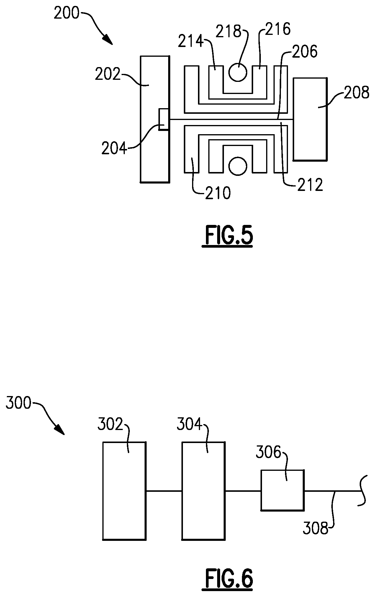
FIG. 5 shows another embodiment.
FIG. 6 shows yet another embodiment.
DETAILED DESCRIPTION
A portion of a gas turbine engine 10 is shown schematically in FIG. 1. The turbine engine 10 includes a fixed housing 12 that is constructed from numerous pieces secured to one another. A compressor section 14 having compressor hubs 16 with blades are driven by a turbine shaft 25 about an axis A. A turbo fan 18 is supported on a turbo fan shaft 20 that is driven by a compressor shaft 24, which supports the compressor hubs 16, through an epicyclic gear train 22. The engine 10 is a high-bypass geared architecture aircraft engine. In one disclosed, non-limiting embodiment, the engine 10 bypass ratio is greater than about six (6) to ten (10), the gear train 22 is an epicyclic gear train such as a planetary gear system or other gear system with a gear reduction ratio of greater than about 2.3 and the low pressure turbine 18 has a pressure ratio that is greater than about 5. The engine 10 in one non-limiting embodiment is a high-bypass geared architecture aircraft engine. In one disclosed embodiment, the engine 10 bypass ratio is greater than ten (10:1), the turbofan diameter is significantly larger than that of the low pressure compressor 16, and the low pressure turbine 27a (shown schematically) has a pressure ratio that is greater than 5:1. As understood, the low pressure turbine 27a is downstream of at least one upstream, or high pressure turbine. The gear train 22 may be an epicycle gear train such as a planetary gear system or other gear system with a gear reduction ratio of greater than 2.5:1. It should be understood, however, that the above parameters are only exemplary of one embodiment of a geared architecture engine and that the present invention is applicable to other gas turbine engines including direct drive turbofans.
A significant amount of thrust is provided by the bypass flow B due to the high bypass ratio. The fan 18 of the engine 10 is designed for a particular flight condition--typically cruise at about 0.8 M and about 35,000 feet. The flight condition of 0.8 M and 35,000 ft, with the engine at its best fuel consumption--also known as "bucket cruise TSFC"--is the industry standard parameter of lbm of fuel being burned divided by lbf of thrust the engine produces at that minimum point. "Low fan pressure ratio" is the pressure ratio across the fan blade alone, without the FEGV system 36. The low fan pressure ratio as disclosed herein according to one non-limiting embodiment is less than 1.45. "Low corrected fan tip speed" is the actual fan tip speed in ft/sec divided by an industry standard temperature correction of [(Tambient deg R)/518.7){circumflex over ( )}0.5]. The "Low corrected fan tip speed" as disclosed herein according to one non-limiting embodiment is less than 1150 ft/second.
The gear train 22 generally includes a fan drive gear system (FDGS) 100 driven by the compressor shaft 24 through an input coupling 102. The input coupling 102 both transfers torque from the compressor shaft 24 to the gear train 22 and facilitates the segregation of vibrations and other transients therebetween.
The input coupling 102 may include an interface spline 102 joined, by a gear spline 106, to the sun gear 30. The sun gear 30 is in meshed engagement with multiple star gears 32. Each star gear 32 is also in meshed engagement with rotating ring gear 38 that is mechanically connected to the fan shaft 20. Since the star gears 32 mesh with both the rotating ring gear 38 as well as the rotating sun gear 30, the star gears 32 rotate about their own axes to drive the ring gear 38. The rotation of the ring gear 38 is conveyed to the fan 20 through the fan shaft 20 to thereby drive the fan 18 at a lower speed than the turbine shaft 25.
In the example arrangement shown, the epicyclic gear train 22 is a star gear train. Referring to FIG. 2, the epicyclic gear train 22 includes the sun gear 30 that is connected to the compressor shaft 24, which provides rotational input, by the splined connection. A carrier 26 is fixed to the housing 12 by a torque frame 28 using fingers (not shown) known in the art. The carrier 26 supports star gears 32 using journal bearings 34 that are coupled to the sun gear 30 by meshed interfaces between the teeth of sun and star gears 30, 32. Multiple star gears 32 are arranged circumferentially about the sun gear 30. Retainers 36 retain the journal bearings 34 to the carrier 26. A ring gear 38 surrounds the carrier 26 and is coupled to the star gears 32 by meshed interfaces. The ring gear 38, which provides rotational output, is secured to the turbo fan shaft 20 by circumferentially arranged fastening elements, which are described in more detail below.
The torque frame 28 supports the carrier 26 with respect to the housing 12 such as a front center body which facilitates the segregation of vibrations and other transients therebetween. It should be understood that various gas turbine engine case structures may alternatively or additionally be provided.
The fixed housing 12 may further include a number 1 and 1.5 bearing support frame 108 which is commonly referred to as a "K-frame" which supports the number 1 and number 1.5 bearing systems 110A, 110B to support the fan shaft 20 (FIG. 1). The number 1 and number 1.5 bearing systems 110A, 110B may include tapered roller bearings which provide a line contact.
Referring to FIGS. 3 and 4, the ring gear 38 is a two-piece construction having first and second portions 40, 42. The first and second portions 40, 42 abut one another at a radial interface 45. A trough 41 separates oppositely angled teeth 43 (best shown in FIG. 4) on each of the first and second portions 40, 42. The arrangement of teeth 43 forces the first and second portions 40, 42 toward one another at the radial interface 45. The back side of the first and second portions 40, 42 includes a generally S-shaped outer circumferential surface 47 that, coupled with a change in thickness, provides structural rigidity and resistance to overturning moments. The first and second portions 40, 42 have a first thickness T1 that is less than a second thickness T2 arranged axially inwardly from the first thickness T1. The first and second portions 40, 42 include facing recesses 44 that form an internal annular cavity 46.
The first and second portions 40, 42 include flanges 51 that extend radially outward away from the teeth 43. The turbo fan shaft 20 includes a radially outwardly extending flange 70 that is secured to the flanges 51 by circumferentially arranged bolts 52 and nuts 54, which axially constrain and affix the turbo fan shaft 20 and ring gear 38 relative to one another. Thus, the spline ring is eliminated, which also reduces heat generated from windage and churning that resulted from the sharp edges and surface area of the splines. The turbo fan shaft 20 and ring gear 38 can be rotationally balanced with one another since radial movement resulting from the use of splines is eliminated. An oil baffle 68 is also secured to the flanges 51, 70 and balanced with the assembly.
Seals 56 having knife edges 58 are secured to the flanges 51, 70. The first and second portions 40, 42 have grooves 48 at the radial interface 45 that form a hole 50, which expels oil through the ring gear 38 to a gutter 60 that is secured to the carrier 26 with fasteners 61 (FIG. 2). The direct radial flow path provided by the grooves 48 reduces windage and churning by avoiding the axial flow path change that existed with splines. That is, the oil had to flow radially and then axially to exit through the spline interface. The gutter 60 is constructed from a soft material such as aluminum so that the knife edges 58, which are constructed from steel, can cut into the aluminum if they interfere. Referring to FIG. 3, the seals 56 also include oil return passages 62 provided by first and second slots 64 in the seals 56, which permit oil on either side of the ring gear 38 to drain into the gutter 60. In the example shown in FIG. 2, the first and second slots 64, 66 are instead provided in the flange 70 and oil baffle 68, respectively.
FIG. 5 shows an embodiment 200, wherein there is a fan drive turbine 208 driving a shaft 206 to in turn drive a fan rotor 202. A gear reduction 204 may be positioned between the fan drive turbine 208 and the fan rotor 202. This gear reduction 204 may be structured and operate like the gear reduction disclosed above. A compressor rotor 210 is driven by an intermediate pressure turbine 212, and a second stage compressor rotor 214 is driven by a turbine rotor 216. A combustion section 218 is positioned intermediate the compressor rotor 214 and the turbine section 216.
FIG. 6 shows yet another embodiment 300 wherein a fan rotor 302 and a first stage compressor 304 rotate at a common speed. The gear reduction 306 (which may be structured as disclosed above) is intermediate the compressor rotor 304 and a shaft 308 which is driven by a low pressure turbine section.
Although a preferred embodiment of this invention has been disclosed, a worker of ordinary skill in this art would recognize that certain modifications would come within the scope of this invention. For that reason, the following claims should be studied to determine the true scope and content of this invention.
* * * * *
References
-
scribd.com/document/153900429/GasTurb-12
-
gasturb.de/about-gasturb.html
-
-
datathief.org/DatathiefManual.pdfpp
-
cfmaeroengines.com
-
en.wikipedia.org/wiki/Torsion_spring
-
-
researchgate.net/post/What_is_the_mesh_stiffness_of_gears
-
ntrs.nasa.gov/archive/nasa/casi.ntrs.nasa.gov/19800075257.pdf
-
mmsonline.com/articles/composite-fan-blade-containment-casepp
-
pyrografproducts.com/Merchant5/merchant.mvc?Screen=cp_nanofiber
-
jet-engine.net/civtfspec.html
-
smartcockpit.com/docs/F900EX-Engines.pdfpp
-
cgabusinessdesk.com/document/aviation_tech_review.pdf
-
catalog.wshampshire.com/Asset/psg_teflon_ptfe.pdf
-
bloomberg.com/news/articles/2016-06-30/ge-wins-shot-to-invalidate-pratt-airplane-engine-patent-in-u-s
-
geaviation.com/sites/default/files/datasheet-CF6-80C2.pdf
-
geaviation.com/commercial/engines/ge90-engine
-
-
-
D00000
D00001
D00002
D00003
XML
uspto.report is an independent third-party trademark research tool that is not affiliated, endorsed, or sponsored by the United States Patent and Trademark Office (USPTO) or any other governmental organization. The information provided by uspto.report is based on publicly available data at the time of writing and is intended for informational purposes only.
While we strive to provide accurate and up-to-date information, we do not guarantee the accuracy, completeness, reliability, or suitability of the information displayed on this site. The use of this site is at your own risk. Any reliance you place on such information is therefore strictly at your own risk.
All official trademark data, including owner information, should be verified by visiting the official USPTO website at www.uspto.gov. This site is not intended to replace professional legal advice and should not be used as a substitute for consulting with a legal professional who is knowledgeable about trademark law.