Rare earth based hydrogen storage alloy and application thereof
Yan , et al. Feb
U.S. patent number 10,566,614 [Application Number 15/507,133] was granted by the patent office on 2020-02-18 for rare earth based hydrogen storage alloy and application thereof. This patent grant is currently assigned to Baotou Research Institute of Rare Earths, National Engineering Research Centre of Rare Earth Metallurgy and Function Materials, Tianjin Baogang Research Institute of Rare Earths Co., Ltd.. The grantee listed for this patent is Baotou Research Institute of Rare Earths, National Engineering Research Centre of Rare Earth Metallurgy and Function Materials, Tianjin Baogang Research Institute of Rare Earths Co., Ltd.. Invention is credited to Baoquan Li, Jin Li, Li Wang, Wei Xiong, Huizhong Yan.


View All Diagrams
| United States Patent | 10,566,614 |
| Yan , et al. | February 18, 2020 |
Rare earth based hydrogen storage alloy and application thereof
Abstract
The invention relates to a rare earth based hydrogen storage alloy, represented by the general formula (I): RE.sub.xY.sub.yNi.sub.z-a-b-cMn.sub.aAl.sub.bM.sub.cZr.sub.ATi.sub.B (I) wherein RE denotes one or more element(s) selected from La, Ce, Pr, Nd, Sm, Gd; M denotes one or more element(s) selected from Cu, Fe, Co, Sn, V, W. The alloy has favorable pressure-composition-temperature characteristic, high hydrogen storage capacity, high electrochemical capacity. The alloy doesn't contain magnesium element, and the preparation process of the alloy is easy and safe.
| Inventors: | Yan; Huizhong (Baotou, CN), Wang; Li (Baotou, CN), Xiong; Wei (Baotou, CN), Li; Baoquan (Baotou, CN), Li; Jin (Baotou, CN) | ||||||||||
|---|---|---|---|---|---|---|---|---|---|---|---|
| Applicant: |
|
||||||||||
| Assignee: | Baotou Research Institute of Rare
Earths (Baotou, Neimenggu, CN) National Engineering Research Centre of Rare Earth Metallurgy and Function Materials (Baotou, Neimenggu, CN) Tianjin Baogang Research Institute of Rare Earths Co., Ltd. (Tianjin, CN) |
||||||||||
| Family ID: | 55398767 | ||||||||||
| Appl. No.: | 15/507,133 | ||||||||||
| Filed: | August 27, 2015 | ||||||||||
| PCT Filed: | August 27, 2015 | ||||||||||
| PCT No.: | PCT/CN2015/088274 | ||||||||||
| 371(c)(1),(2),(4) Date: | February 27, 2017 | ||||||||||
| PCT Pub. No.: | WO2016/029861 | ||||||||||
| PCT Pub. Date: | March 03, 2016 |
Prior Publication Data
| Document Identifier | Publication Date | |
|---|---|---|
| US 20170288217 A1 | Oct 5, 2017 | |
Foreign Application Priority Data
| Aug 28, 2014 [CN] | 2014 1 0427179 | |||
| Aug 28, 2014 [CN] | 2014 1 0427199 | |||
| Aug 28, 2014 [CN] | 2014 1 0427220 | |||
| Aug 28, 2014 [CN] | 2014 1 0427259 | |||
| Aug 28, 2014 [CN] | 2014 1 0427281 | |||
| Aug 28, 2014 [CN] | 2014 1 0429187 | |||
| Aug 28, 2014 [CN] | 2014 1 0429202 | |||
| Current U.S. Class: | 1/1 |
| Current CPC Class: | C22C 19/03 (20130101); C22C 1/023 (20130101); H01M 10/345 (20130101); H01M 4/383 (20130101); C22C 19/007 (20130101); C22C 28/00 (20130101); C22C 2202/04 (20130101); H01M 2004/027 (20130101) |
| Current International Class: | H01M 4/38 (20060101); H01M 10/34 (20060101); C22C 19/03 (20060101); C22C 19/00 (20060101); C22C 1/02 (20060101); C22C 28/00 (20060101); H01M 4/02 (20060101) |
| 101170173 | Apr 2008 | CN | |||
| 101355155 | Jan 2009 | CN | |||
| 102828069 | Dec 2012 | CN | |||
| 103700895 | Apr 2014 | CN | |||
| 104152749 | Nov 2014 | CN | |||
| 104513915 | Apr 2015 | CN | |||
| 104513916 | Apr 2015 | CN | |||
| 104513925 | Apr 2015 | CN | |||
| 104518204 | Apr 2015 | CN | |||
| 104532062 | Apr 2015 | CN | |||
| 104532095 | Apr 2015 | CN | |||
| WO 02/101855 | Dec 2002 | WO | |||
Other References
|
State Intellectual Property Office of the People's Republic of China, International Search Report issued in International Patent Application No. PCT/CN2015/088274 (dated Dec. 4, 2015) 6 pp. cited by applicant . State Intellectual Property Office of the People's Republic of China, First Office Action issued in Chinese Patent Application No. 201410427179.9, (dated Feb. 3, 2016) 11 pp. cited by applicant . State Intellectual Property Office of the People's Republic of China, Second Office Action issued in Chinese Patent Application No. 201410427179.9, (dated Sep. 19, 2016) 13 pp. cited by applicant . State Intellectual Property Office of the People's Republic of China, First Office Action issued in Chinese Patent Application No. 201410427199.6, (dated Dec. 17, 2015) 11 pp. cited by applicant . State Intellectual Property Office of the People's Republic of China, Second Office Action issued in Chinese Patent Application No. 201410427199.6, (dated Jun. 27, 2016) 13 pp. cited by applicant . State Intellectual Property Office of the People's Republic of China, First Office Action issued in Chinese Patent Application No. 201410427220.2, (dated Feb. 3, 2016) 10 pp. cited by applicant . State Intellectual Property Office of the People's Republic of China, Second Office Action issued in Chinese Patent Application No. 201410427220.2, dated Sep. 19, 2016) 13 pp. cited by applicant . State Intellectual Property Office of the People's Republic of China, First Office Action issued in Chinese Patent Application No. 201410427259.4, (dated Jun. 2, 2016) 12 pp. cited by applicant . State Intellectual Property Office of the People's Republic of China, Second Office Action issued in Chinese Patent Application No. 201410427259.4, (dated Jan. 23, 2017) 13 pp. cited by applicant . State Intellectual Property Office of the People's Republic of China, Third Office Action issued in Chinese Patent Application No. 201410427259.4, (dated Jul. 3, 2017) 17 pp. cited by applicant . State Intellectual Property Office of the People's Republic of China, First Office Action issued in Chinese Patent Application No. 201410427281.9, (dated Feb. 3, 2016) 15 pp. cited by applicant . State Intellectual Property Office of the People's Republic of China, Second Office Action issued in Chinese Patent Application No. 201410427281.9, (dated Jul. 13, 2016) 17 pp. cited by applicant . State Intellectual Property Office of the People's Republic of China, First Office Action issued in Chinese Patent Application No. 201410429187.7, (dated Mar. 24, 2016) 14 pp. cited by applicant . State Intellectual Property Office of the People's Republic of China, Second Office Action issued in Chinese Patent Application No. 201410429187.7, (dated Nov. 28, 2016) 14 pp. cited by applicant . State Intellectual Property Office of the People's Republic of China, Third Office Action issued in Chinese Patent Application No. 201410429187.7, (dated Jun. 5, 2017) 11 pp. cited by applicant . State Intellectual Property Office of the People's Republic of China, First Office Action issued in Chinese Patent Application No. 201410429202.8, (dated Feb. 3, 2016) 14 pp. cited by applicant . State Intellectual Property Office of the People's Republic of China, Notification of Grant issued in Chinese Patent Application No. 201410429202.8, (dated Oct. 9, 2016) 3 pp. cited by applicant . Latroche et al., "Crystallographic and hydriding properties of the system La.sub.1-xCe.sub.xY.sub.2Ni.sub.9 (Xc.sub.e = 0, 0.5 and 1)," Journal of Solid State Chemistry, 173: 236-243 (2003). cited by applicant . State Intellectual Property Office of the People's Republic of China, Office Action issued in Chinese Patent Application No. 201580046681.8 (dated May 11, 2018) 11 pp. cited by applicant. |
Primary Examiner: Nassiri-Motlagh; Anita
Attorney, Agent or Firm: Leydig, Voit & Mayer, Ltd.
Claims
The invention claimed is:
1. A rare earth based hydrogen storage alloy represented by the general formula (I): RE.sub.xY.sub.yNi.sub.z-a-b-cMn.sub.aAl.sub.bM.sub.cZr.sub.ATi.sub.B (I) wherein RE denotes one or more element(s) selected from the group consisting of La, Ce, Pr, Nd, Sm, and Gd; M denotes one or more element(s) selected from the group consisting of Cu, Fe, Co, Sn, V, and W; x>0, y.gtoreq.0.5, and x+y=3, 13.gtoreq.z.gtoreq.7; 6.gtoreq.a+b>0, 5.gtoreq.c.gtoreq.0, and 4.gtoreq.A+B.gtoreq.0.
2. The rare earth based hydrogen storage alloy according to claim 1, wherein x>0, y.gtoreq.0.5, x+y=3; 12.5.gtoreq.z.gtoreq.8.5; 5.5.gtoreq.a+b>0, 3.5.gtoreq.c.gtoreq.0, and 2.5.gtoreq.A+B.gtoreq.0.
3. The rare earth based hydrogen storage alloy according to claim 2, wherein c=0 and A=B=0.
4. The rare earth based hydrogen storage alloy according to claim 3, wherein 12.5.gtoreq.z.gtoreq.11.
5. The rare earth based hydrogen storage alloy according to claim 3, wherein 11>z.gtoreq.9.5; and 4.5.gtoreq.a+b>0.
6. The rare earth based hydrogen storage alloy according to claim 3, wherein 9.5>z.gtoreq.8.5; and 3.5.gtoreq.a+b>0.
7. The rare earth based hydrogen storage alloy according to claim 2, wherein A=B=0, and c>0.
8. The rare earth based hydrogen storage alloy according to claim 7, wherein 3.5.gtoreq.a+b.gtoreq.0; and 3.0.gtoreq.c>0.
9. The rare earth based hydrogen storage alloy according to claim 2, wherein 2.5.gtoreq.A+B>0.
10. The rare earth based hydrogen storage alloy according to claim 9, wherein 12.5.gtoreq.z.gtoreq.11, and 4.gtoreq.a+b>0.
11. The rare earth based hydrogen storage alloy according to claim 9, wherein 11>z.gtoreq.9.5; 3.5.gtoreq.a+b>0; and 3.gtoreq.c.gtoreq.0.
12. The rare earth based hydrogen storage alloy according to claim 9, wherein 9.5>z.gtoreq.8.5; 3.gtoreq.a+b>0; and 2.5.gtoreq.c.gtoreq.0.
13. The rare earth based hydrogen storage alloy according to claim 1, wherein one or more of the following items i)-iv) apply: i) 2.0.gtoreq.x.gtoreq.0.5; ii) 3.0.gtoreq.a.gtoreq.0.5; iii) 1.5.gtoreq.b.gtoreq.0.3; iv) z=11.4.
14. The rare earth based hydrogen storage alloy according to claim 1, wherein one or more of the following items i)-iv) apply: i) 2.0.gtoreq.x.gtoreq.0.5; ii) 2.5.gtoreq.a.gtoreq.0.5; iii) 1.0.gtoreq.b.gtoreq.0.2; iv) z=10.5.
15. The rare earth based hydrogen storage alloy according to claim 1, wherein one or more of the following items i)-iv) apply: i) 2.0.gtoreq.x.gtoreq.0.5; ii) 2.0.gtoreq.a.gtoreq.0.5; iii) 1.0.gtoreq.b.gtoreq.0.2; iv) z=9.
16. The rare earth based hydrogen storage alloy according to claim 1, wherein one or more of the following items i)-v) apply: i) 2.0.gtoreq.x.gtoreq.0.5; ii) 2.0.gtoreq.a.gtoreq.0.5; iii) 1.0.gtoreq.b.gtoreq.0.3; iv) 11.4.gtoreq.z.gtoreq.9; v) 2.5.gtoreq.c.gtoreq.0.1.
17. The rare earth based hydrogen storage alloy according to claim 1, wherein one or more of the following items i)-vii) apply: i) 2.gtoreq.x.gtoreq.0.5; ii) 2.5.gtoreq.a.gtoreq.0.5; iii) 1.0.gtoreq.b.gtoreq.0.2; iv) z=11.4; v) 2.5.gtoreq.c.gtoreq.0.1; vi) 1.0.gtoreq.A.gtoreq.0.1; vii) 1.0.gtoreq.B.gtoreq.0.1.
18. The rare earth based hydrogen storage alloy according to claim 1, wherein one or more of the following items i)-vii) apply: i) 2.0.gtoreq.x.gtoreq.0.5; ii) 2.0.gtoreq.a.gtoreq.0.5; iii) 1.0.gtoreq.b.gtoreq.0.2; iv) z=10.5; v) 2.0.gtoreq.c.gtoreq.0.1; vi) 1.0.gtoreq.A.gtoreq.0.1; vii) 1.0.gtoreq.B.gtoreq.0.1.
19. The rare earth based hydrogen storage alloy according to claim 1, wherein one or more of the following items i)-vii) apply: i) 2.0.gtoreq.x.gtoreq.0.5; ii) 2.0.gtoreq.a.gtoreq.0.5; iii) 1.0.gtoreq.b.gtoreq.0.2; iv) z=9; v) 2.0.gtoreq.c.gtoreq.0.1; vi) 1.0.gtoreq.A.gtoreq.0.1; vii) 1.0.gtoreq.B.gtoreq.0.1.
20. The rare earth based hydrogen storage alloy according to claim 1, wherein one or more of the following items i)-iii) apply: i) the alloy has a maximum hydrogen storage capacity of 1.2-1.5 wt % at 313K; ii) when utilized as a negative material electrode for a Ni-MH battery, the alloy has a maximum discharge capacity of 300-400 mAh/g at a current density of 70 mA/g; iii) the alloy has a capacity retention of more than 85%, at a current density of 70 mA/g.
21. A hydrogen storage medium comprising the rare earth based hydrogen storage alloy according to claim 1.
22. An electrode of a secondary battery comprising the rare earth based hydrogen storage alloy according to claim 1.
23. A secondary battery comprising the rare earth based hydrogen storage alloy according to claim 1.
Description
CROSS-REFERENCE TO RELATED APPLICATIONS
This patent application is the U.S. national phase of International Application No. PCT/CN2015/088274, filed on Aug. 27, 2015, which claims priority from Chinese Application Nos. 201410427179.9, 201410427199.6, 201410427220.2, 201410427259.4, 201410427281.9, 201410429187.7, and 201410429202.8, all filed on Aug. 28, 2014, the disclosures of which are incorporated herein by reference in their entireties for all purposes.
TECHNICAL FIELD
The invention belongs to the field of hydrogen storage alloy, and relates to a rare earth based hydrogen storage alloy and the application thereof.
BACKGROUND
Hydrogen storage alloy is a functional material with high hydrogen-storage density. At present, hydrogen storage alloy could be roughly divided into six categories: rare earth based AB.sub.5 type, such as LaNi.sub.5; magnesium based, such as Mg.sub.2Ni, MgNi, La.sub.2Mg.sub.17; rare earth-magnesium-nickel based AB.sub.3-4 type, such as La.sub.2MgNi.sub.9, La.sub.5Mg.sub.2Ni.sub.23, La.sub.3MgNi.sub.14; titanium based AB type, such as TiNi, TiFe; zirconium or titanium based AB.sub.2 type with Laves phase, such as ZrNi.sub.2; vanadium based solid solution type as (V.sub.0.9Ti.sub.0.1).sub.1-xFe.sub.x.
The hydrogen-storage material widely used nowadays is LaNi.sub.5 type hydrogen-storage alloy. The alloy is mainly used as a negative material of a metal hydride-nickel(MH-Ni) secondary battery, with a theoretical electrochemical capacity of about 373 mAhg.sup.-1. The commercial negative material electrode materials in actual application is Mm(NiCoMnAl).sub.5 (wherein Mm denotes mixed rare earths), which has a maximum capacity of 350 mAhg.sup.-1. In order to develop hydrogen-storage alloys with better electrochemical properties or higher hydrogen storage capacity, the research of magnesium based alloy has become a hotspot. Magnesium based alloys have high theoretical capacity. Especially, great progresses have been made in the study of rare earth-magnesium-nickel based AB.sub.3 type, A.sub.2B.sub.7 type and A.sub.5B.sub.19 type alloys and these alloys has been put into industrial application. Titanium, zirconium and vanadium based hydrogen storage materials were not widely used due to their disadvantages such as poor activation characteristic, high cost, etc.
CN201310228766.0 discloses an A.sub.2B.sub.7 type hydrogen storage alloy for nickel-hydride battery and preparation method thereof. The composition of the alloy conforms to the general formula Ln.sub.aMg.sub.bNi.sub.xY.sub.yZ.sub.z, wherein Ln denotes one or more rare earth element(s), Y denotes one or more element(s) selected from Al, Co, Nb, V, Fe, Cu, Zn, As, Ga, Mo, Sn, In, W, Si and P, and Z denotes one or more element(s) selected from Ag, Sr, Ge, 0.5.ltoreq.a<2, 0<b<1, 5<X+Y+Z<9, 0<Y<3, 0<Z<1.
CN101210294A discloses a A.sub.5B.sub.19 type alloy. The alloy has a formula of X.sub.5-aY.sub.aZ.sub.b, wherein X denotes one or more of rear earth metals, Y denotes one or more of alkaline earth metal(s), Z denotes one or more element(s) selected from Mn, Al, V, Fe, Si, Sn, Ni, Co, Cr, Cu, Mo, Zn and B, 0<a.ltoreq.2, 17.5.ltoreq.b.ltoreq.22.5.
CN102195041A discloses a hydrogen storage alloy for an alkaline storage battery. The alloy has a formula of La.sub.xRe.sub.yMg.sub.1-x-yNi.sub.n-m-vAl.sub.mT.sub.v, wherein Re denotes at least one rare earth element(s) including Y(ytterbium)(except La), T denotes at least one element(s) selected from Co, Mn and Zn; 0.17.ltoreq.x.ltoreq.0.64, 3.5.ltoreq.n.ltoreq.3.8, 0.06.ltoreq.m.ltoreq.0.22, v.gtoreq.0. The main phase of the alloy is A.sub.5B.sub.19 type crystal structure.
CN101238231A discloses a hydrogen storage alloy. The alloy contains a phase of Pr.sub.5Co.sub.19 type crystal structure, which conforms to the general formula A.sub.(4-w)B.sub.(1+w)C.sub.19, wherein A denotes one or more element(s) selected from rare earth elements including Y (yttrium); B denotes Mg element; C denotes one or more element(s) selected from Ni, Co, Mn, and Al; and w denotes a numeral in a range from -0.1 to 0.8; and the alloy have a composition as a whole defined by the general formula R1.sub.xR2.sub.yR3.sub.z, wherein 15.8.ltoreq.x.ltoreq.17.8, 3.4.ltoreq.y.ltoreq.5.0, 78.8.ltoreq.z.ltoreq.79.6, and x+y+z=100; R1 denotes one or more element(s) selected from rare earth elements including Y (yttrium); R2 denotes an Mg element, R3 denotes one or more element(s) selected from Ni, Co, Mn, and Al; z is 0.5 or higher when it denotes the stoichiometric number of Mn+Al; z is 4.1 or lower when it denotes the stoichiometric number of Al.
CN102660700A discloses an AB.sub.3 type hydrogen storage alloy and preparation method thereof. The chemical formula of the AB.sub.3 type hydrogen storage alloy is La.sub.0.35Pr.sub.0.30Mg.sub.xNi.sub.2.90Al.sub.0.30, wherein x=0.30.about.0.35.
CN102195041A discloses a hydrogen storage alloy for an alkaline storage battery, the composition of which conforms to the general formula La.sub.xRe.sub.yMg.sub.1-x-yNi.sub.n-m-vAl.sub.mT.sub.v (Re: rare earth elements including Y; T: Co, Mn, Zn; 0.17.ltoreq.x.ltoreq.0.64, 3.5.ltoreq.n.ltoreq.3.8, 0.06.ltoreq.m.ltoreq.0.22, v.gtoreq.0), and the alloy's main phase has a A.sub.5B.sub.19-type crystal structure.
CN103326004A discloses an A.sub.2B.sub.7 hydrogen storage alloy for a nickel metal hydride battery and preparation method thereof. The alloy conforms to the structural general formula: Ln.sub.aMg.sub.bNi.sub.xY.sub.yZ.sub.z, wherein Ln denotes at least one element selected from rare earth elements; Y denotes least one element selected from Al, Co, Nb, V, Fe, Cu, Zn, As, Ga, Mo, Sn, In, W, Si and P; Z denotes at least one element selected from Ag, Sr and Ge; 0.5.ltoreq.a<2, 0<b<1, 5<X+Y+Z<9, 0<Y<3, 0<Z<1.
The above alloys do not contain Y element, or do not contain Zr element, or do not contain Ti element. However, they all contain alkaline earth metals or magnesium element. Because the vapor pressure of active metal element magnesium is high, the difficulty of manufacturing the alloy is increased, and the composition of the alloy is difficult to control. The escaped micro-fine magnesium powder is flammable and combustible, which is a potential safety hazards.
Researches of "An electrochemical study of new La.sub.1-xCe.sub.xY.sub.2Ni.sub.9 (0.ltoreq.x.ltoreq.1) hydrogen storage alloys" (Electrochimica Acta, 46 (2001): 2385-2393) and "New ternary intermetallic compounds belonging to the R--Y--Ni(R.dbd.La, Ce) system as negative material electrodes for Ni-MH batteries" (Journal of Alloys and Compounds, 330-332 (2002): 782-786) report an AB.sub.3 type La--Y--Ni hydrogen storage alloy. Nevertheless, the alloy doesn't contain Mn and Al, and its maximum hydrogen storage capacity is only 260 mAhg.sup.-1.
SUMMARY
An object of the invention is to provide a rare earth based hydrogen storage alloy with high hydrogen storage capacity. Another object of the invention is to provide a rare earth based hydrogen storage alloy with high electrochemical capacity. Another object of the invention is to provide a rare earth based hydrogen storage alloy which is easy to prepare, or the composition of which is easy to control, or the preparation process of which is safe.
In order to achieve one or more of the above objects, according to the first aspect of the present application, provided is a rare earth based hydrogen storage alloy represented by the general formula (I): RE.sub.xY.sub.yNi.sub.z-a-b-cMn.sub.aAl.sub.bM.sub.cZr.sub.ATi.sub.B (I)
wherein RE denotes one or more element(s) selected from La, Ce, Pr, Nd, Sm, Gd; M denotes one or more element(s) selected from Cu, Fe, Co, Sn, V, W; x>0, y.gtoreq.0.5, x+y=3, 13.gtoreq.z.gtoreq.7; 6.gtoreq.a+b>0, 5.gtoreq.c.gtoreq.0, 4.gtoreq.A+B.gtoreq.0.
In a preferred embodiment for the rare earth based hydrogen storage alloy of the invention represented by the general formula (I), x>0, y.gtoreq.0.5, x+y=3; 12.5.gtoreq.z.gtoreq.8.5; 5.5.gtoreq.a+b>0, 3.5.gtoreq.c.gtoreq.0, 2.5.gtoreq.A+B.gtoreq.0.
In a preferred embodiment for the rare earth based hydrogen storage alloy of the invention represented by the general formula (I), RE denotes La and/or Ce.
In another preferred embodiment for the rare earth based hydrogen storage alloy of the invention represented by the general formula (I), RE denotes La.
In another preferred embodiment for the rare earth based hydrogen storage alloy of the invention represented by the general formula (I), RE denotes Ce.
In another preferred embodiment for the rare earth based hydrogen storage alloy of the invention represented by the general formula (I), RE denotes mischmetal consisting of La and Ce, preferably the atomic ratio of La and Ce is 0.8:0.2.
In another preferred embodiment for the rare earth based hydrogen storage alloy of the invention represented by the general formula (I), RE denotes Lanthanum-rich mischmetal wherein La accounts for about 64 wt %, Ce accounts for about 25 wt %, Pr accounts for about 3 wt % and Nd accounts for about 8 wt %.
In a preferred embodiment for the rare earth based hydrogen storage alloy of the invention represented by the general formula (I), 2.5.gtoreq.A+B>0.
In a preferred embodiment for the rare earth based hydrogen storage alloy of the invention represented by the general formula (I), c=0, A=B=0.
In a preferred embodiment for the rare earth based hydrogen storage alloy of the invention represented by the general formula (I), 11>z.gtoreq.9.5, 4.5.gtoreq.a+b>0.
In a preferred embodiment for the rare earth based hydrogen storage alloy of the invention represented by the general formula (I), 12.5.gtoreq.z.gtoreq.11, 5.5.gtoreq.a+b>0.
In a preferred embodiment for the rare earth based hydrogen storage alloy of the invention represented by the general formula (I), 9.5>z.gtoreq.8.5; 3.5.gtoreq.a+b>0.
In a preferred embodiment for the rare earth based hydrogen storage alloy of the invention represented by the general formula (I), A=B=0, c>0.
In another preferred embodiment for the rare earth based hydrogen storage alloy of the invention represented by the general formula (I), 3.5.gtoreq.a+b.gtoreq.0; 3.0.gtoreq.c>0.
In a preferred embodiment for the rare earth based hydrogen storage alloy of the invention represented by the general formula (I), c=0, A=B=0, 11>z.gtoreq.9.5, 4.5.gtoreq.a+b>0. In such embodiment, the rare earth based hydrogen storage alloy of the invention represented by the general formula (I) may be represented by the general formula (I-1): RE.sub.xY.sub.yNi.sub.z-a-bMn.sub.aAl.sub.b (I-1)
wherein: RE denotes one or more element(s) selected from La, Ce, Pr, Nd, Sm, Gd; x>0, y.gtoreq.0.5, x+y=3; 11>z.gtoreq.9.5; 4.5.gtoreq.a+b>0. When z=10.5, the hydrogen storage alloy is stoichiometric A.sub.2B.sub.7 type; when z.noteq.10.5, the hydrogen storage alloy is non-stoichiometric A.sub.2B.sub.7 type.
In a preferred embodiment for the rare earth based hydrogen storage alloy represented by the general formula (I-1), 2.5.gtoreq.x.gtoreq.0.5, preferably 2.0.gtoreq.x.gtoreq.0.5, further preferably 1.2.gtoreq.x.gtoreq.0.8.
In another preferred embodiment for the rare earth based hydrogen storage alloy represented by the general formula (I-1), 2.5.gtoreq.a.gtoreq.0, preferably 2.5.gtoreq.a.gtoreq.0.5, further preferably 0.6.gtoreq.a.gtoreq.0.4.
In another preferred embodiment for the rare earth based hydrogen storage alloy represented by the general formula (I-1), 1.0.gtoreq.b.gtoreq.0, preferably 1.0.gtoreq.b.gtoreq.0.2, or preferably 0.3.gtoreq.b.gtoreq.0.
In another preferred embodiment for the rare earth based hydrogen storage alloy represented by the general formula (I-1), 10.8.gtoreq.z.gtoreq.9.5, preferably z=10.5.
In another preferred embodiment for the rare earth based hydrogen storage alloy represented by the general formula (I-1), 2.0.gtoreq.x.gtoreq.0.5, 2.5.gtoreq.a.gtoreq.0.5, 1.0.gtoreq.b.gtoreq.0.2, z=10.5.
In a preferred embodiment for the rare earth based hydrogen storage alloy of the invention represented by the general formula (I), c=0, A=B=0, 12.5.gtoreq.z.gtoreq.11. In such embodiment, the rare earth based hydrogen storage alloy of the invention represented by the general formula (I) may be represented by the general formula (I-1): RE.sub.xY.sub.yNi.sub.z-a-bMn.sub.aAl.sub.b (I-1)
wherein RE denotes one or more element(s) selected from La, Ce, Pr, Nd, Sm, Gd; x>0, y.gtoreq.0.5, x+y=3; 12.5.gtoreq.z.gtoreq.11; 5.5.gtoreq.a+b>0. When z=11.4, the hydrogen storage alloy is stoichiometric A.sub.5B.sub.19 type; when z.noteq.11.4, the hydrogen storage alloy is non-stoichiometric A.sub.5B.sub.19 type.
In a preferred embodiment for the rare earth based hydrogen storage alloy represented by the general formula (I-1), 2.5.gtoreq.x.gtoreq.0.5, preferably 2.0.gtoreq.x.gtoreq.0.5, further preferably 1.5.gtoreq.x.gtoreq.1.
In another preferred embodiment for the rare earth based hydrogen storage alloy represented by the general formula (I-1), 3.0.gtoreq.a.gtoreq.0, preferably 3.0.gtoreq.a.gtoreq.0.5, further preferably 1.0.gtoreq.a.gtoreq.0.5.
In another preferred embodiment for the rare earth based hydrogen storage alloy represented by the general formula (I-1), 1.5.gtoreq.b.gtoreq.0, preferably 1.5.gtoreq.b.gtoreq.0.3, further preferably 0.5.gtoreq.b.gtoreq.0;
In another preferred embodiment for the rare earth based hydrogen storage alloy represented by the general formula (I-1), 12.5.gtoreq.z.gtoreq.11, preferably 11.4.gtoreq.z.gtoreq.11.0 further preferably z=11.4.
In another preferred embodiment for the rare earth based hydrogen storage alloy represented by the general formula (I-1), 2.0.gtoreq.x.gtoreq.0.5, 3.0.gtoreq.a.gtoreq.0.5, 1.5.gtoreq.b.gtoreq.0.3, z=11.4.
In another preferred embodiment for the rare earth based hydrogen storage alloy of the invention represented by the general formula (I), c=0, A=B=0, 9.5>z.gtoreq.8.5; 3.5.gtoreq.a+b>0. In such embodiment, the rare earth based hydrogen storage alloy of the invention represented by the general formula (I) may be represented by the general formula (I-1): RE.sub.xY.sub.yNi.sub.z-a-bMn.sub.aAl.sub.b (I-1)
wherein RE denotes one or more element(s) selected from La, Ce, Pr, Nd, Sm, Gd, x>0, y.gtoreq.0.5, x+y=3; 9.5>z.gtoreq.8.5, 3.5.gtoreq.a+b>0. When z=9, the hydrogen storage alloy is stoichiometric AB.sub.3 type; when z.noteq.9, the hydrogen storage alloy is non-stoichiometric AB.sub.3 type.
In a preferred embodiment for the rare earth based hydrogen storage alloy represented by the general formula (I-1), 2.5.gtoreq.x.gtoreq.0.5, preferably 2.0.gtoreq.x.gtoreq.0.5.
In another preferred embodiment for the rare earth based hydrogen storage alloy represented by the general formula (I-1), 2.gtoreq.a.gtoreq.0; preferably 2.gtoreq.a.gtoreq.0.5.
In another preferred embodiment for the rare earth based hydrogen storage alloy represented by the general formula (I-1), 1.0.gtoreq.b.gtoreq.0, preferably 1.0.gtoreq.b.gtoreq.0.2.
In another preferred embodiment for the rare earth based hydrogen storage alloy represented by the general formula (I-1), 9.5.gtoreq.z.gtoreq.8.5, preferably z=9.
In another further preferably embodiment for the rare earth based hydrogen storage alloy represented by the general formula (I-1), 2.0.gtoreq.x.gtoreq.0.5, 2.0.gtoreq.a.gtoreq.0.5, 1.0.gtoreq.b.gtoreq.0.2, z=9.
In another preferred embodiment for the rare earth based hydrogen storage alloy represented by the general formula (I-1), RE denotes La and/or Ce.
In another preferred embodiment for the rare earth based hydrogen storage alloy represented by the general formula (I-1), RE denotes La.
In another preferred embodiment for the rare earth based hydrogen storage alloy represented by the general formula (I-1), RE denotes Ce.
In another preferred embodiment for the rare earth based hydrogen storage alloy represented by the general formula (I-1), RE denotes mischmetal consisting of La and Ce, preferably wherein the atomic ratio of La and Ce is 0.8:0.2.
In another preferred embodiment for the rare earth based hydrogen storage alloy represented by the general formula (I-1), RE denotes Lanthanum-rich mischmetal, La accounts for about 64 wt %, Ce accounts for about 25 wt %, Pr accounts for about 3 wt % and Nd accounts for about 8 wt %.
In another preferred embodiment for the rare earth based hydrogen storage alloy of the invention represented by the general formula (I), A=B=0, 3.5.gtoreq.a+b.gtoreq.0; 3.0.gtoreq.c>0. In such embodiment, the rare earth based hydrogen storage alloy of the invention represented by the general formula (I) may be represented by the general formula (I-2): RE.sub.xY.sub.yNi.sub.z-a-b-cMn.sub.aAl.sub.bM.sub.c (I-2)
wherein RE denotes one or more element(s) selected from La, Ce, Pr, Nd, Sm, Gd, M denotes one or more element(s) selected from Cu, Fe, Co, Sn, V, W; x>0, y.gtoreq.0.5, x+y=3; 12.5.gtoreq.z.gtoreq.8.5, 3.5.gtoreq.a+b>0, 3.0.gtoreq.c>0.
In a preferred embodiment for the rare earth based hydrogen storage alloy represented by the general formula (I-2), 2.5.gtoreq.x.gtoreq.0.5, preferably 2.0.gtoreq.x.gtoreq.0.5, further preferably 1.2.gtoreq.x.gtoreq.1.
In another preferred embodiment for the rare earth based hydrogen storage alloy represented by the general formula (I-2), 2.0.gtoreq.a.gtoreq.0.5, preferably 1.gtoreq.a.gtoreq.0.5.
In another preferred embodiment for the rare earth based hydrogen storage alloy represented by the general formula (I-2), 1.0.gtoreq.b.gtoreq.0.3; preferably 0.5.gtoreq.b.gtoreq.0.3.
In another preferred embodiment for the rare earth based hydrogen storage alloy represented by the general formula (I-2), 12.5.gtoreq.z.gtoreq.8.5, preferably 11.4.gtoreq.z.gtoreq.9, further preferably 11.gtoreq.z.gtoreq.10.
In another preferred embodiment for the rare earth based hydrogen storage alloy represented by the general formula (I-2), 2.5.gtoreq.c.gtoreq.0.1, preferably 1.gtoreq.c.gtoreq.0.5.
In another preferred embodiment for the rare earth based hydrogen storage alloy represented by the general formula (I-2), 2.0.gtoreq.x.gtoreq.0.5, 2.0.gtoreq.a.gtoreq.0.5, 1.0.gtoreq.b.gtoreq.0.3, 2.5.gtoreq.c.gtoreq.0.1, 11.4.gtoreq.z.gtoreq.9.
In another preferred embodiment for the rare earth based hydrogen storage alloy represented by the general formula (I-2), RE denotes La and/or Ce.
In another preferred embodiment for the rare earth based hydrogen storage alloy represented by the general formula (I-2), RE denotes La.
In another preferred embodiment for the rare earth based hydrogen storage alloy represented by the general formula (I-2), RE denotes Ce.
In another preferred embodiment for the rare earth based hydrogen storage alloy represented by the general formula (I-2), RE denotes mischmetal consisting of La and Ce, preferably the atomic ratio of La and Ce is 0.8:0.2.
In another preferred embodiment for the rare earth based hydrogen storage alloy represented by the general formula (I-2), RE denotes Lanthanum-rich mischmetal, La accounts for about 64 wt %, Ce accounts for about 25 wt %, Pr accounts for about 3 wt % and Nd accounts for about 8 wt %.
In a preferred embodiment for the rare earth based hydrogen storage alloy of the invention represented by the general formula (I), 12.5.gtoreq.z.gtoreq.11, 4.gtoreq.a+b>0.
In another preferred embodiment for the rare earth based hydrogen storage alloy of the invention represented by the general formula (I), RE denotes one or more element(s) selected from La, Ce, Pr, Nd, Sm, Gd, x>0, y.gtoreq.0.5, x+y=3; M denotes one or more element(s) selected from Cu, Fe, Co, Sn, V, W, 12.5.gtoreq.z.gtoreq.11 (when z=11.4, the alloy is stoichiometric A.sub.5B.sub.19 type; when z.noteq.11.4, the alloy is non-stoichiometric A.sub.5B.sub.19 type), 4.gtoreq.a+b>0, 3.5.gtoreq.c.gtoreq.0, 2.5.gtoreq.A+B>0;
preferably, 2.5.gtoreq.x.gtoreq.0.5, further preferably, 2.0.gtoreq.x.gtoreq.0.5;
preferably, 2.5.gtoreq.a.gtoreq.0, further preferably, 2.5.gtoreq.a.gtoreq.0.5;
preferably, 1.0.gtoreq.b.gtoreq.0, further preferably, 1.0.gtoreq.b.gtoreq.0.2, still further preferably, 0.5.gtoreq.b.gtoreq.0;
preferably, 2.5.gtoreq.a.gtoreq.0.5, 1.0.gtoreq.b.gtoreq.0.2;
preferably, 2.5.gtoreq.c.gtoreq.0, further preferably, 2.5.gtoreq.c.gtoreq.0.1, still further preferably, 0.5.gtoreq.c.gtoreq.0;
preferably, 1.0.gtoreq.A.gtoreq.0, further preferably, 1.0.gtoreq.A.gtoreq.0.1, still further preferably, 0.5.gtoreq.A.gtoreq.0.1;
preferably, 1.0.gtoreq.B.gtoreq.0, further preferably, 1.0.gtoreq.B.gtoreq.0.1, still further preferably, 0.3.gtoreq.B.gtoreq.0;
preferably, z=11.4.
In a preferably embodiment for the rare earth based hydrogen storage alloy of the invention represented by the general formula (I), RE denotes one or more element(s) selected from La, Ce, Pr, Nd, Sm, Gd; M denotes one or more element(s) selected from Cu, Fe, Co, Sn, V, W, 2.0.gtoreq.x.gtoreq.0.5, 2.5.gtoreq.a.gtoreq.0.5, 1.0.gtoreq.b.gtoreq.0.2, 2.5.gtoreq.c.gtoreq.0.1, 1.0.gtoreq.A.gtoreq.0.1, 1.0.gtoreq.B.gtoreq.0.1, z=11.4.
In a preferred embodiment for the rare earth based hydrogen storage alloy of the invention represented by the general formula (I), 11>z.gtoreq.9.5; 3.5.gtoreq.a+b>0; 3.gtoreq.c.gtoreq.0.
In another preferred embodiment for the rare earth based hydrogen storage alloy of the invention represented by the general formula (I), RE denotes one or more element(s) selected from La, Ce, Pr, Nd, Sm, Gd, x>0, y.gtoreq.0.5, x+y=3; M denotes one or more element(s) selected from Cu, Fe, Co, Sn, V, W, 11>z.gtoreq.9.5 (when z=10.5, the alloy is stoichiometric A.sub.2B.sub.7 type; when z.noteq.10.5, the alloy is non-stoichiometric A.sub.2B.sub.7 type), 3.5.gtoreq.a+b>0, 3.gtoreq.c.gtoreq.0, 2.gtoreq.A+B>0;
preferably 2.5.gtoreq.x.gtoreq.0.5, further preferably 2.0.gtoreq.x.gtoreq.0.5;
preferably 2.0.gtoreq.a.gtoreq.0, further preferably 2.0.gtoreq.a.gtoreq.0.5, further preferably 1.0.gtoreq.a.gtoreq.0.5;
preferably 1.0.gtoreq.b.gtoreq.0, further preferably 1.0.gtoreq.b.gtoreq.0.2, further preferably 0.5.gtoreq.b.gtoreq.0;
preferably 2.0.gtoreq.c.gtoreq.0, further preferably 2.0.gtoreq.c.gtoreq.0.1, further preferably 0.5.gtoreq.c.gtoreq.0;
preferably 1.0.gtoreq.A.gtoreq.0.1, further preferably 0.5.gtoreq.A.gtoreq.0.1;
preferably 1.0.gtoreq.B.gtoreq.0.1, further preferably 0.3.gtoreq.B.gtoreq.0.1;
preferably 10.8.gtoreq.z.gtoreq.9.5, further preferably z=10.5.
In another preferred embodiment for the rare earth based hydrogen storage alloy of the invention represented by the general formula (I), RE denotes one or more element(s) selected from La, Ce, Pr, Nd, Sm, Gd, M denotes one or more element(s) selected from Cu, Fe, Co, Sn, V, W, 2.0.gtoreq.x.gtoreq.0.5, 2.0.gtoreq.a.gtoreq.0.5, 1.0.gtoreq.b.gtoreq.0.2, 2.0.gtoreq.c.gtoreq.0.1, 1.0.gtoreq.A.gtoreq.0.1, 1.0.gtoreq.B.gtoreq.0.1, z=10.5.
In a preferred embodiment for the rare earth based hydrogen storage alloy of the invention represented by the general formula (I), 9.5>z.gtoreq.8.5; 3.gtoreq.a+b>0; 2.5.gtoreq.c.gtoreq.0.
In another preferred embodiment for the rare earth based hydrogen storage alloy of the invention represented by the general formula (I), RE denotes one or more element(s) selected from La, Ce, Pr, Nd, Sm, Gd, x>0, y.gtoreq.0.5, x+y=3; M denotes one or more element(s) selected from Cu, Fe, Co, Sn, V, W, 9.5>z.gtoreq.8.5 (when z=9, the alloy is stoichiometric AB.sub.3 type; when z.noteq.9, the alloy is non-stoichiometric AB.sub.3 type), 3.gtoreq.a+b>0, 2.5.gtoreq.c.gtoreq.0, 2.gtoreq.A+B>0;
preferably 2.5.gtoreq.x.gtoreq.0.5, further preferably 2.0.gtoreq.x.gtoreq.0.5, further preferably 1.2.gtoreq.x.gtoreq.0.8, for example, x=1;
preferably 2.0.gtoreq.a.gtoreq.0, further preferably 2.0.gtoreq.a.gtoreq.0.5, further preferably 0.6.gtoreq.a.gtoreq.0.4, for example, a=0.5;
preferably 1.0.gtoreq.b.gtoreq.0, further preferably 1.0.gtoreq.b.gtoreq.0.2, further preferably 0.5.gtoreq.b.gtoreq.0;
preferably 2.0.gtoreq.c.gtoreq.0, further preferably 2.0.gtoreq.c.gtoreq.0.1, further preferably 0.5.gtoreq.c.gtoreq.0;
preferably 1.0.gtoreq.A.gtoreq.0, further preferably 1.0.gtoreq.A.gtoreq.0.1, further preferably 0.5.gtoreq.A.gtoreq.0.1;
preferably 1.0.gtoreq.B.gtoreq.0, further preferably 1.0.gtoreq.B.gtoreq.0.1, further preferably 0.3.gtoreq.B.gtoreq.0.2;
preferably 9.4.gtoreq.z.gtoreq.8.5, further preferably 9.4.gtoreq.z.gtoreq.9, further preferably z=9.
In another preferred embodiment for the rare earth based hydrogen storage alloy of the invention represented by the general formula (I), RE denotes one or more element(s) selected from La, Ce, Pr, Nd, Sm and Gd; M denotes one or more element(s) selected from Cu, Fe, Co, Sn, V and W, 2.0.gtoreq.x.gtoreq.0.5, 2.0.gtoreq.a.gtoreq.0.5, 1.0.gtoreq.b.gtoreq.0.2, 2.0.gtoreq.c.gtoreq.0.1, 1.0.gtoreq.A.gtoreq.0.1, 1.0.gtoreq.B.gtoreq.0.1, z=9.
In an embodiment for the rare earth based hydrogen storage alloy of the invention represented by the general formula (I), x may be 0.1, 0.2, 0.3 or 0.4, x may also be 0.5, 0.6 or 0.7, x may also be 0.8, 0.9 or 1, x may also be 1.1, 1.2 or 1.3, x may also be 1.4, 1.5 or 1.6, x may also be 1.7, 1.8 or 1.9, x may also be 2, 2.1 or 2.2, x may also be 2.3, 2.4 or 2.5.
In an embodiment for the rare earth based hydrogen storage alloy of the invention represented by the general formula (I), y may be 0.5, 0.6 or 0.7, y may also be 0.8, 0.9 or 1, y may also be 1.1, 1.2 or 1.3, y may also be 1.4, 1.5 or 1.6, y may also be 1.7, 1.8 or 1.9, y may also be 2, 2.1 or 2.2, y may also be 2.3, 2.4 or 2.5, y may also be 2.6, 2.7, 2.8 or 2.9.
In an embodiment for the rare earth based hydrogen storage alloy of the invention represented by the general formula (I), a may be 0, a may also be 0.1, 0.2, 0.3, 0.4 or 0.5, a may also be 0.6, 0.7, 0.8, 0.9 or 1, a may also be 1.1, 1.2, 1.3, 1.4 or 1.5, a may also be 1.6, 1.7, 1.8, 1.9 or 2, a may also be 2.1, 2.2, 2.3, 2.4 or 2.5, a may also be 2.6, 2.7, 2.8, 2.9 or 3.
In an embodiment for the rare earth based hydrogen storage alloy of the invention represented by the general formula (I), b may be 0, b may also be 0.1, 0.2 or 0.3, b may also be 0.4, 0.5 or 0.6, b may also be 0.7, 0.8 or 0.9, b may also be 1.
In an embodiment for the rare earth based hydrogen storage alloy of the invention represented by the general formula (I), z may be 8.5, 8.6, 8.7, 8.8, 8.9 or 9, z may also be 9.1, 9.2, 9.3, 9.4 or 9.5, z may also be 9.6, 9.7, 9.8, 9.9 or 10, z may also be 10.1, 10.2, 10.3, 10.4 or 10.5, z may also be 10.6, 10.7, 10.8, 10.9 or 11, z may also be 11.1, 11.2, 11.3, 11.4 or 11.5, z may also be 11.6, 11.7, 11.8, 11.9 or 12, z may also be 12.1, 12.2, 12.3, 12.4 or 12.5.
In an embodiment for the rare earth based hydrogen storage alloy of the invention represented by the general formula (I), c may be 0, c may also be 0.1, 0.2, 0.3, 0.4 or 0.5, c may also be 0.6, 0.7, 0.8, 0.9 or 1, c may also be 1.1, 1.2, 1.3, 1.4 or 1.5, c may also be 1.6, 1.7, 1.8, 1.9 or 2, c may also be 2.1, 2.2, 2.3, 2.4 or 2.5, c may also be 2.6, 2.7, 2.8, 2.9 or 3, c may also be 3.1, 3.2, 3.3, 3.4 or 3.5.
In an embodiment for the rare earth based hydrogen storage alloy of the invention represented by the general formula (I), A may be 0, A may also be 0.1, 0.2 or 0.3, A may also be 0.4, 0.5 or 0.6, A may also be 0.7, 0.8 or 0.9, A may also be 1.
In an embodiment for the rare earth based hydrogen storage alloy of the invention represented by the general formula (I), B may be 0, B may also be 0.1, 0.2 or 0.3, B may also be 0.4, 0.5 or 0.6, B may also be 0.7, 0.8 or 0.9, B may also be 1.
In an embodiment for the rare earth based hydrogen storage alloy of the invention represented by the general formula (I), x may be 0.5, 1, 1.2, 1.5, 2 or 2.5, x may also be 1, 1.2 or 1.5.
In an embodiment for the rare earth based hydrogen storage alloy of the invention represented by the general formula (I), y may be 0.5, 1, 1.5, 1.8, 2 or 2.5, y may also be 1.5, 1.8 or 2.
In an embodiment for the rare earth based hydrogen storage alloy of the invention represented by the general formula (I), a may be 0, 0.5, 0.8, 1, 1.5, 2, 2.5 or 3, a may also be 0.5, 0.8, 1, 1.5, 2 or 2.5.
In an embodiment for the rare earth based hydrogen storage alloy of the invention represented by the general formula (I), b may be 0, 0.2, 0.3, 0.5, 0.8, 1 or 1.5, b may also be 0, 0.2, 0.3 or 0.5.
In an embodiment for the rare earth based hydrogen storage alloy of the invention represented by the general formula (I), c may be 0, 0.1, 0.2, 0.5, 1, 1.5, 2 or 2.5, c may also be 0, 0.1 or 0.5.
In an embodiment for the rare earth based hydrogen storage alloy of the invention represented by the general formula (I), A may be 0, 0.1, 0.2, 0.3, 0.5 or 1, A may also be 0.1, 0.3 or 0.5.
In an embodiment for the rare earth based hydrogen storage alloy of the invention represented by the general formula (I), B may be 0, 0.1, 0.2, 0.3, 0.5 or 1, B may also be 0, 0.1, 0.2 or 0.3.
In an embodiment for the rare earth based hydrogen storage alloy of the invention represented by the general formula (I), when z=9, the alloy is stoichiometric AB.sub.3 type; when z.noteq.9, the alloy is non-stoichiometric AB.sub.3 type.
In an embodiment for the rare earth based hydrogen storage alloy of the invention represented by the general formula (I), when z=10.5, the alloy is stoichiometric A.sub.2B.sub.7 type; z.noteq.10.5, the alloy is non-stoichiometric A.sub.2B.sub.7 type.
In an embodiment for the rare earth based hydrogen storage alloy of the invention represented by the general formula (I), when z=11.4, the alloy is stoichiometric A.sub.5B.sub.19 type; z.noteq.11.4, the alloy is non-stoichiometric A.sub.5B.sub.19 type.
In an embodiment for the rare earth based hydrogen storage alloy of the invention represented by the general formula (I), comprises one or more phase(s) selected from Y.sub.2Ni.sub.7, La.sub.2Ni.sub.7, LaNi.sub.5, Ni.sub.5Y, Ce.sub.2Ni.sub.7, Al.sub.2Ni.sub.6Y.sub.3 and LaY.sub.2Ni.sub.9.
In an embodiment for the rare earth based hydrogen storage alloy of the invention represented by the general formula (I), comprises one or more phase(s) selected from Y.sub.2Ni.sub.7, La.sub.2Ni.sub.7, LaNi.sub.5 and Ce.sub.2Ni.sub.7.
In an embodiment for the rare earth based hydrogen storage alloy of the invention represented by the general formula (I), comprises one or more phase(s) selected from Y.sub.2Ni.sub.7, La.sub.2Ni.sub.7, LaNi.sub.5 and Al.sub.2Ni.sub.6Y.sub.3.
In an embodiment for the rare earth based hydrogen storage alloy of the invention represented by the general formula (I), comprises one or more phase(s) selected from Y.sub.2Ni.sub.7 and LaY.sub.2Ni.sub.9.
In an embodiment for the rare earth based hydrogen storage alloy of the invention represented by the general formula (I), comprises one or more phase(s) selected from Y.sub.2Ni.sub.7 and La.sub.2Ni.sub.7, Ni.sub.5Y.
In an embodiment for the rare earth based hydrogen storage alloy of the invention represented by the general formula (I), comprises LaY.sub.2Ni.sub.9 phase.
In an embodiment for the rare earth based hydrogen storage alloy of the invention represented by the general formula (I), comprises one or more phase(s) selected from Y.sub.2Ni.sub.7 and La.sub.2Ni.sub.7.
In an embodiment for the rare earth based hydrogen storage alloy of the invention represented by the general formula (I) comprises Y.sub.2Ni.sub.7 phase.
In an embodiment for the rare earth based hydrogen storage alloy of the invention represented by the general formula (I) has a maximum hydrogen storage capacity of 1.2.about.1.5 wt %, preferably 1.3.about.1.5 wt %, optionally 1.2.about.1.4 wt % or 1.3.about.1.4 wt %, at a temperature of 313K,
In an embodiment, when used as a negative material electrode for a Ni-MH battery, the rare earth based hydrogen storage alloy of the invention represented by the general formula (I) has a maximum discharge capacity of 300.about.400 mAh/g, preferably 350.about.400 mAh/g, further preferably 370.about.400 mAh/g, still further preferably 380.about.400 mAh/g, at a current density of 70 mA/g. The cut-off discharge voltage may be 1.0V.
In an embodiment, when used as a negative material electrode for a Ni-MH battery, the rare earth based hydrogen storage alloy of the invention represented by the general formula (I) has a capacity retention of more than 85%, preferably more than 90%, more preferably more than 95%, still further preferably more than 98% after 100 cycles of charge and discharge, at a current density of 70 mA/g. The cut-off discharge voltage may be 1.0V.
According to the second aspect of the present application, provided is use of the rare earth based hydrogen storage alloy of the invention represented by the general formula (I) of the invention as a hydrogen storage medium.
According to the third aspect of the present application, provided is use of the rare earth based hydrogen storage alloy of the invention represented by the general formula (I) of the invention in manufacturing an electrode of a secondary battery.
The rare earth based hydrogen storage alloy of the invention represented by the general formula (I) of the invention may be manufactured into electrode, and the electrode could be made into a secondary battery coupled with other suitable materials. The secondary battery made from the rare earth based hydrogen storage alloy of the invention represented by the general formula (I) of the invention can be discharged and recharged for multiple times.
The rare earth based hydrogen storage alloy of the invention represented by the general formula (I) of the invention could be produced by a method comprising the following steps:
(i) providing raw materials according to the composition of the alloy product;
(ii) smelting the raw materials;
(iii) rapidly solidifying the smelted raw materials on a copper roller;
preferably, the linear speed of the copper roller in step (iii) is 3-4 m/s, and the copper roller is supplied with cooling water.
In an embodiment, in the method of preparing the rare earth based hydrogen storage alloy of the invention, after the step of rapidly solidifying, the prepared alloy is annealed at 700.about.800.degree. C. for 6.about.10 hours, e.g. at 750.degree. C. for 8 hours, under vacuum or inert gas.
In an embodiment, the hydrogen storage alloy of the invention may be produced by high temperature smelting-rapidly quenching method comprising the following steps: providing components satisfying the stoichiometric ratio of the chemical formula by weighing each raw material accurately, wherein the purity of each elemental metal or intermediate alloy used as raw material is greater than 99.0%; putting the raw materials into an Al.sub.2O.sub.3 crucible in sequence, vacuuming the crucible to a pressure of 3.0 Pa, and then filling the crucible with an inert gas Ar to a pressure of 0.055 MPa; smelting the raw materials, keeping the temperature of the smelted raw materials for about 6 minutes and then performing rapidly quenching. The linear speed of the copper roller used for rapidly quenching is 3.4 m/s. The copper roller is cooled with cooling water having a temperature of 25.degree. C.
In an embodiment, in the method of preparing the rare earth based hydrogen storage alloy of the invention, the mass ratio of the raw materials which is prior to loss by burning are increased at an appropriate amount, the increase rate is shown in the following table:
TABLE-US-00001 raw material RE Y Mn Al increase rate 2% 1% 5% 3%
Besides the abovementioned methods, the hydrogen storage alloy represented by the general formula (I) of the invention may be produced by other methods for producing hydrogen storage alloys, such as: high-temperature smelting and casting method, mechanical alloying (MA) method, powder sintering method, high-temperature smelting and gas atomization method, reduction diffusion method, replacement-diffusion method, combustion synthesis (CS) method or self-propagating high temperature synthesis (SHS) method.
According to the fourth aspect of the invention, provided is the rare earth based hydrogen storage alloy represented by the general formula (I) as a hydrogen storage medium.
According to the fifth aspect of the invention, provided is the rare earth based hydrogen storage alloy represented by the general formula (I) for manufacturing an electrode of a secondary battery.
The rare earth based hydrogen storage alloy represented by the general formula (I) could be composited with other hydrogen storage alloys in various proportions to fabricate new hydrogen storage materials.
Heat treatment may be performed to improve the microstructures and properties of the rare earth based hydrogen storage alloy of the invention represented by the general formula (I), for example, to relieve structural stresses and eliminate component segregation, or to improve hydrogen absorption/desorption plateau characteristics or discharge/charge plateau characteristics, or to increase hydrogen storage capacity and cycle life. Various surface treatments may be performed to improve the alloy's performance, such as to improve the kinetics performance of hydrogen absorption/desorption processes or charge/discharge processes of the alloy, or to enhance the antioxidant ability of the alloy, or to improve the electrical/thermal conductivity of the alloy.
In the invention, unless otherwise specified, symbols for elements are consistent with the Periodic Table of Elements. In the general formula (I) of the invention, Y denotes yttrium, Ni denotes nickel, Mn denotes manganese, Al denotes aluminum, Zr denotes zirconium and Ti denotes titanium.
The Beneficial Effects of the Invention
The rare earth based hydrogen storage alloy of the invention represented by the general formula (I) of the invention has one or more of the following advantage(s):
(1) It has a favorable pressure-composition-temperature (P-c-T) feature. Under normal conditions, the hydrogen storage capacity could reach 1.28 wt % or more, the maximum hydrogen storage capacity of the alloy could reach 1.36 wt % or more;
(2) The electrochemical performance and hydrogen gas absorption and desorption performance of the rare earth based hydrogen storage alloy of the invention as hydrogen storage electrode are better than the traditional LaNi.sub.5 type hydrogen storage alloy;
(3) The rare earth based hydrogen storage alloy of the invention doesn't contain magnesium, and therefore the preparation methods of the rare earth based hydrogen storage alloy of the invention is easier and safer compared to that of the traditional rare earth-magnesium-nickel hydrogen storage alloy
(4) The rare earth based hydrogen storage alloy of the invention has favorable activation performance, rate discharge ability, charging/discharging or hydrogen absorbing/desorbing cycling stability. It can work at a wide range of temperature and has a low self-discharge rate.
(5) One of the main components of the rare earth based hydrogen storage alloy of the invention is yttrium (Y). As Yttrium is abundant in rare earth minerals, the application of yttrium is beneficial for comprehensive utilization of rare earth resources of China.
BRIEF DESCRIPTION OF THE DRAWINGS
The drawings described herein are used to provide a further understanding of the invention and constitute a part of this application, in which:
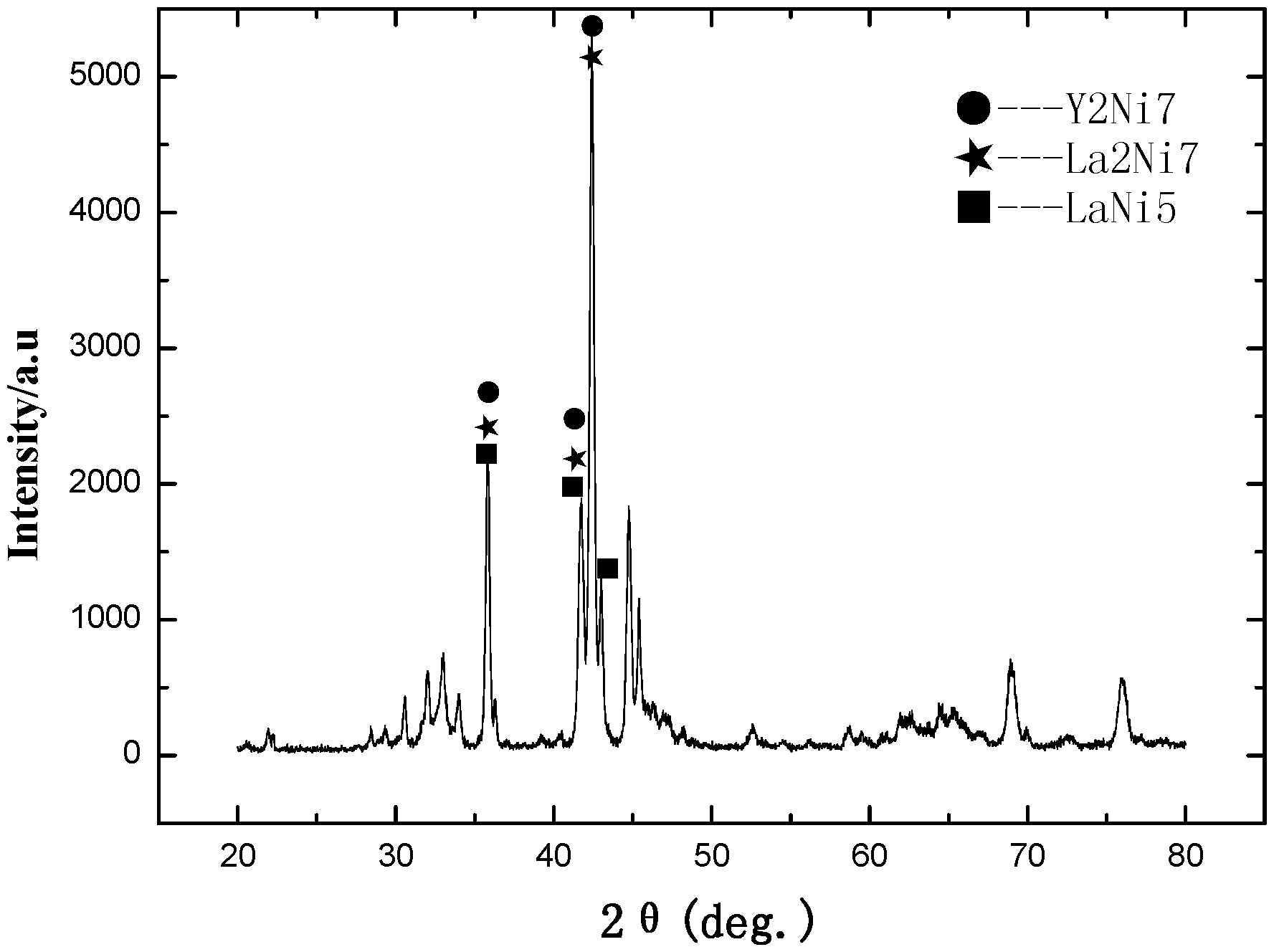
FIG. 1-1 is an XRD pattern of the hydrogen storage alloy, LaCe.sub.0.5Y.sub.1.5Ni.sub.9.7Mn.sub.0.5Al.sub.0.3 (Example A23);
FIG. 1-2 is a redrawn XRD pattern of hydrogen storage alloy, LaCe.sub.0.5Y.sub.1.5Ni.sub.9.7Mn.sub.0.5Al.sub.0.3 according to the original XRD data of FIG. 1-1 (Example A23);
FIG. 1-3 is a P-c-T curve of the hydrogen storage alloy LaY.sub.2Ni.sub.9.5Mn.sub.0.5Al.sub.0.5 (Example A13);
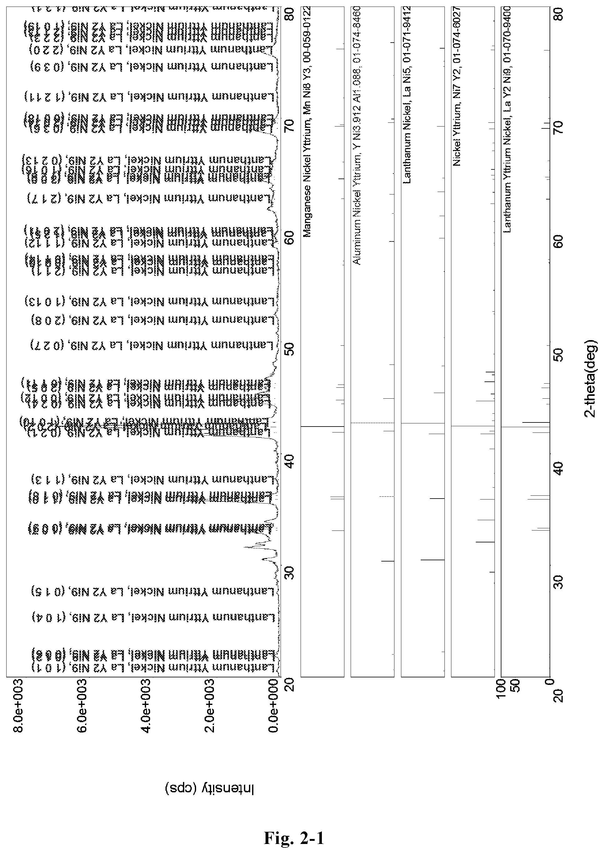
FIG. 2-1 is a XRD pattern of the hydrogen storage alloy LaY.sub.2Ni.sub.10.6Mn.sub.0.5Al.sub.0.3 (Example B2);
FIG. 2-2 is a redrawn XRD pattern of the hydrogen storage alloy LaY.sub.2Ni.sub.10.6Mn.sub.0.5Al.sub.0.3 according to the original XRD data of FIG. 2-1 (Example B2);
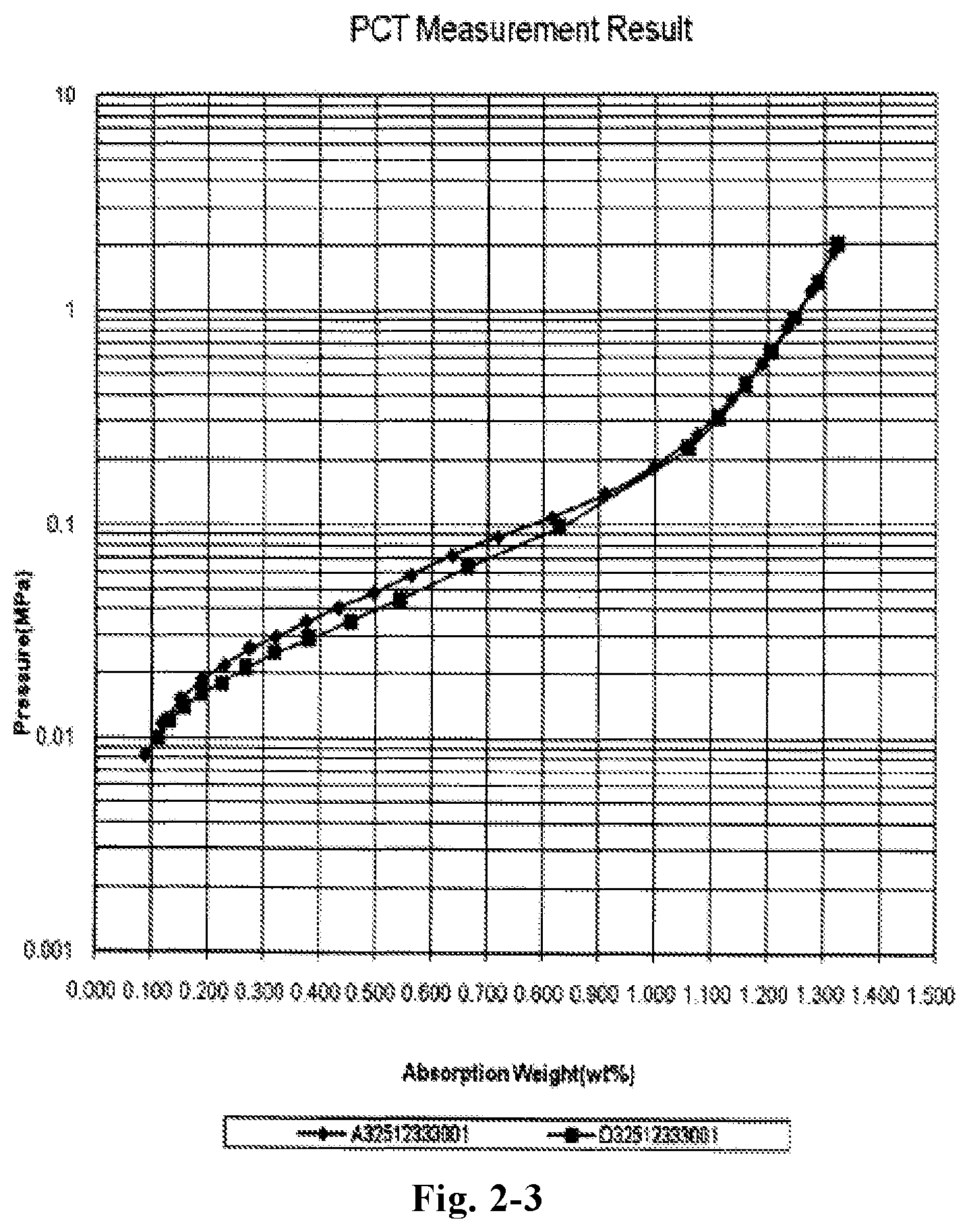
FIG. 2-3 is a P-c-T curve of the hydrogen storage alloy LaY.sub.2Ni.sub.10.6Mn.sub.0.5Al.sub.0.3 (Example B2);
FIG. 3-1 is a XRD pattern of the hydrogen storage alloy LaY.sub.2Ni.sub.8Mn.sub.0.5Al.sub.0.5 (Example C13);
FIG. 3-2 a redrawn XRD pattern of the hydrogen storage alloy LaY.sub.2Ni.sub.8Mn.sub.0.5Al.sub.0.5 according to the original XRD data of FIG. 3-1 (Example C13);
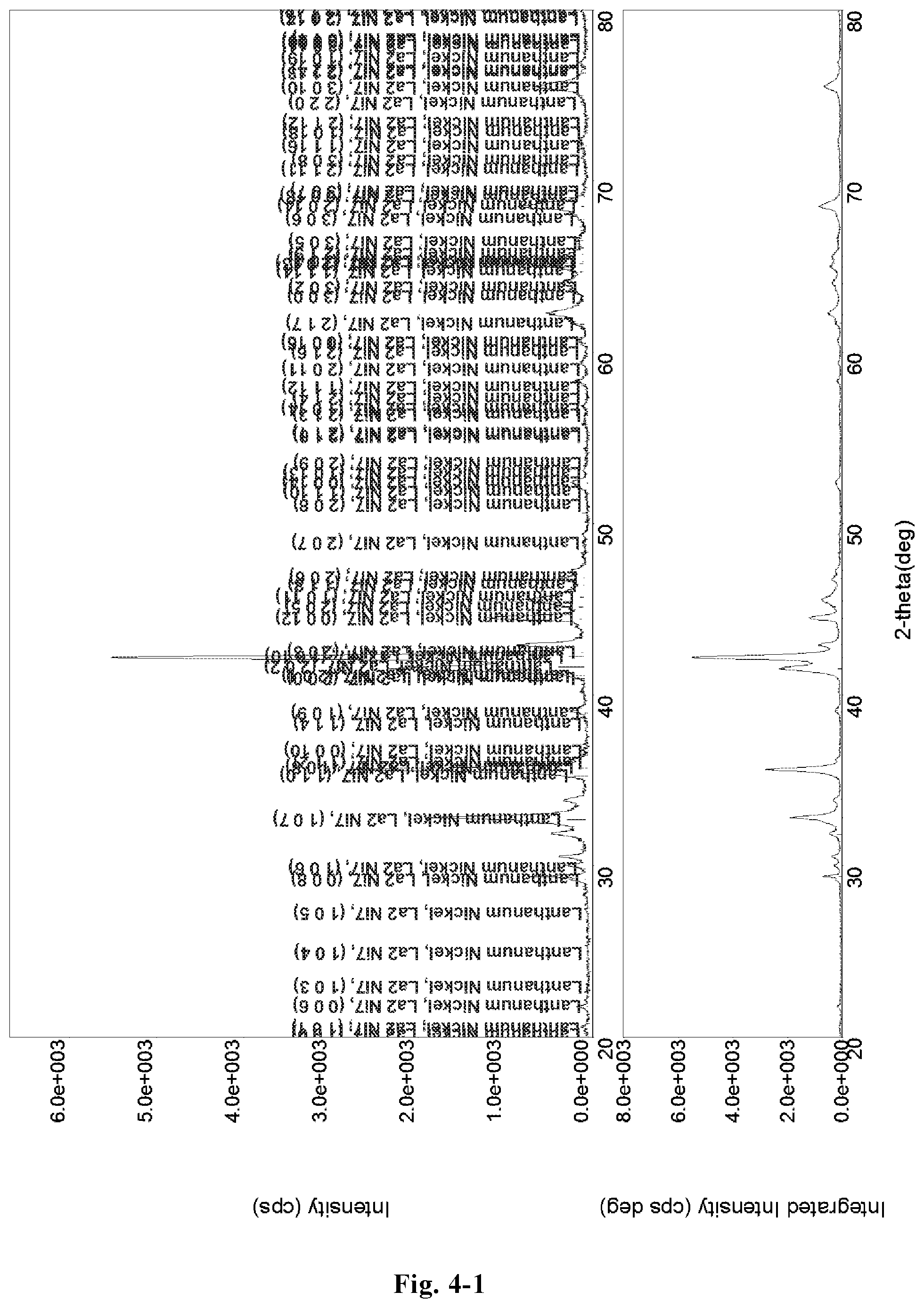
FIG. 4-1 is a XRD pattern of the hydrogen storage alloy La.sub.1.2Y.sub.1.8Ni.sub.9.2Mn.sub.0.5Al.sub.0.3Co.sub.0.5 (Example D28);
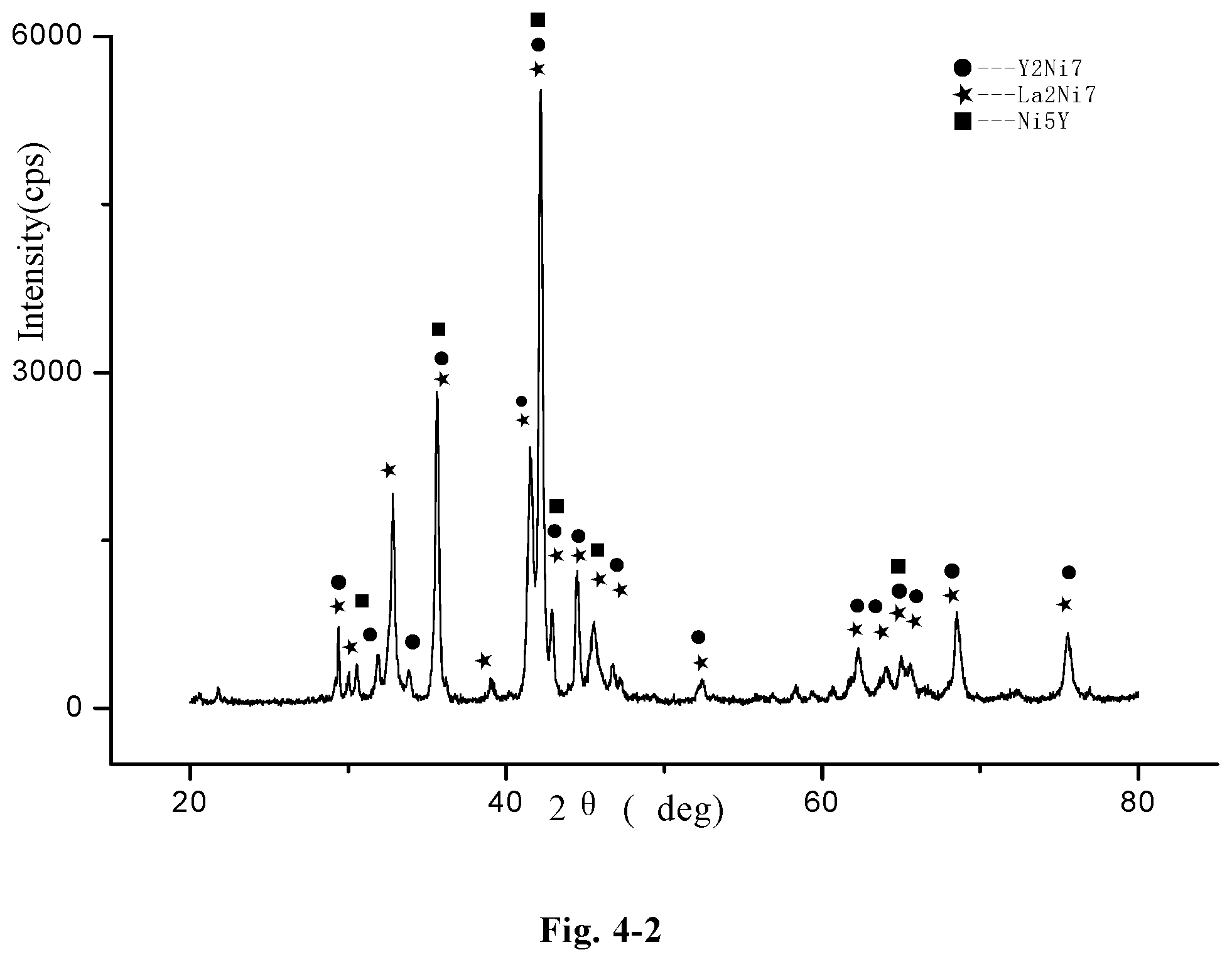
FIG. 4-2 a redrawn XRD pattern of the hydrogen storage alloy La.sub.1.2Y.sub.1.8Ni.sub.9.2Mn.sub.0.5Al.sub.0.3Co.sub.0.5, according to the original XRD data of FIG. 4-1 (Example D28);
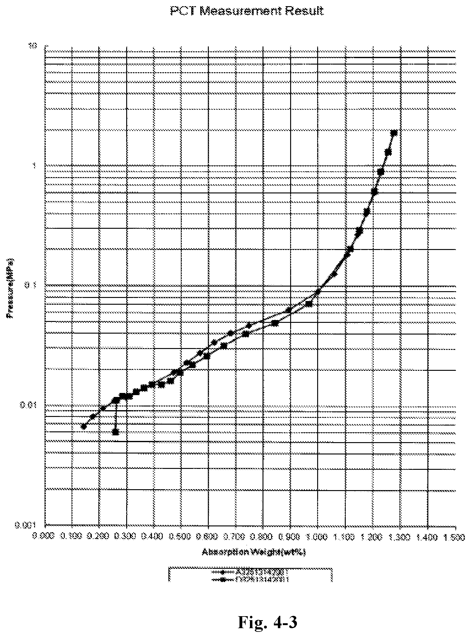
FIG. 4-3 is a pressure-composition-temperature (P-c-T) curve of the alloy LaY.sub.2Ni.sub.9.5Mn.sub.0.5Al.sub.0.3Cu.sub.0.2 (Example D38);
FIG. 5-1 is an XRD pattern of the hydrogen storage alloy La.sub.1.2Y.sub.1.8Ni.sub.9.2Mn.sub.0.5Al.sub.0.3Co.sub.0.5Zr.sub.0.1Ti.s- ub.0.1 (Example E18);
FIG. 5-2 an redrawn XRD pattern of the hydrogen storage alloy, La.sub.1.2Y.sub.1.8Ni.sub.9.2Mn.sub.0.5Al.sub.0.3Co.sub.0.5Zr.sub.0.1Ti.s- ub.0.1, according to the original XRD data of FIG. 5-1 (Example E18);
FIG. 6-1 is an X ray diffraction pattern of the alloy LaY.sub.2Ni.sub.10.6Mn.sub.0.5Al.sub.0.3Zr.sub.0.1 (Example F35);
FIG. 7-1 is an XRD pattern of the hydrogen storage alloy, LaY.sub.2Ni.sub.8.3Mn.sub.0.5Al.sub.0.2Zr.sub.0.1 (Example G18);
FIG. 7-2 a redrawn XRD pattern of the hydrogen storage alloy, LaY.sub.2Ni.sub.8.3Mn.sub.0.5Al.sub.0.2Zr.sub.0.1, according to the original XRD data of FIG. 7-1 (Example G18).
DETAILED DESCRIPTION OF THE EMBODIMENT
The embodiments of the invention are further described with reference to the examples and drawings. The examples and the descriptions thereof are to illustrate the invention, yet not to limit the invention.
In the following examples:
1. phase structure analyses are performed on X-Ray Diffractometer (XRD), with the following test condition: Cu target, Ka radiation, tube voltage 40 kV, tube current 100 mA, scanning angle 2.theta.: 20.about.80.degree., scanning speed: 3.degree./min and scanning step: 0.02.degree..
2. Equipments for measuring hydrogen storage amount include a PCT measuring instrument for hydrogen storage alloy, a thermostatic water bath and an analytical balance. The purity of the hydrogen used in the test is 99.999%.
Measuring procedure includes: crushing the alloy plates, sieving the crushed alloy with a 14 mesh (1200 .mu.m) screen and a 200 mesh (74 .mu.m) screen, collecting about 2.5 g of the alloy powder passing through 200 mesh screen and putting it into a sample container, vacuuming the sample container for 5 min, then charging the container with hydrogen, calibrating the volume of the sample container according to the ideal-gas equation, then vacuuming the sample container for 30 min, keeping the pressure below 0.001 MPa, activating the alloy for 3 times at 353K, then vacuuming the sample container for 2 h, and obtaining a pressure-composition-temperature (PCT) curve at 313K.
3. The rare earth based hydrogen storage alloy is produced by high temperature smelting-rapidly quenching method, the method comprising the following steps: providing components satisfying the stoichiometric ratio of the chemical formula by weighing each raw material accurately, wherein the purity of each elemental metal or intermediate alloy used as raw material is greater than 99.0%; putting the raw materials into an Al.sub.2O.sub.3 crucible in sequence, vacuuming the crucible to a pressure of 3.0 Pa, and then filling the crucible with an inert gas Ar to a pressure of 0.055 MPa; smelting the raw materials, keeping the temperature of the smelted raw materials for about 6 minutes and then performing rapidly quenching. The linear speed of the copper roller used for rapidly quenching is 3.4 m/s. The copper roller is cooled with cooling water having a temperature of 25.degree. C.
4. The electrochemical parameters involved in the following examples include: N, denoting the number of cycles; C.sub.max, denoting the maximum discharge capacity; S.sub.100, denoting the capacity retention ratio after 100 cycles; HRD.sub.350, reflecting the discharge ability under a discharge current density (I.sub.d) of 350 mAg.sup.-1, LTD.sub.243, denoting the capacity retention ratio at a temperature of 243K; SD.sub.72, denoting the capacity retention ratio after the battery being stored for 72 hours (self discharge feature).
High-rate discharge capacity (HRD.sub.350) mainly reflects the dynamics performance of the hydrogen storage electrodes. HRD.sub.350 is calculated according to the following formula:
.times..times. ##EQU00001##
wherein: C.sub.d denotes the discharge capacity measured at a discharge current density (I.sub.d) and a cut-off discharge voltage of 1.0V (vs. Ni(OH).sub.2/NiOOH counter electrode), C.sub.60 denotes the residual discharge capacity measured at a discharge current density of I=60 mAg.sup.-1 and a cut-off voltage of 1.0V after the alloy electrode has been fully discharge at high discharge current density (I.sub.d). HRD.sub.350 denotes the HRD measured at a discharge current density (I.sub.d) of 350 mAg.sup.-1.
LTD.sub.243 reflects the discharge performance at a low temperature of 243K. The low temperature discharge performance (LTD) is calculated according to the following formula:
.times..times. ##EQU00002##
In the formula: C.sub.T denotes the maximum discharge capacity at a current density of 70 mA/g at a low temperature (243K), C.sub.298 denotes the maximum discharge capacity at a current density of 70 mA/g at the normal temperature (298K).
SD.sub.72 denotes the self-discharge rate measured after the battery has been rested for 72 hours. SD.sub.72 reflects the self-discharge ability (charge retention ability). The test condition includes: measuring the discharge capacity C.sub.a by charging a battery for 6 h at a rate of 0.2C, resting the battery for 10 min, discharging the battery to 1.0V at a rate of 0.2C, and then measuring the discharge capacity C.sub.b, by charging the battery at a rate of 0.2C for 6 h, resting the battery for 72 h, discharging the battery to 1.0 V at a rate of 0.2C, and then measuring the discharge capacity C.sub.c by charging and discharging the battery at a rate of 0.2C. SD.sub.72, which denotes the charge retention ratio after the battery being rested for 72 h, is calculated by the following formula: 2C.sub.b/(C.sub.a+C.sub.c).times.100%
Example A1.about.A23
A.sub.2B.sub.7 type RE.sub.xY.sub.yNi.sub.z-a-bMn.sub.aAl.sub.b hydrogen storage alloys in Example A1.about.A23 were produced by applying the high temperature smelting-rapidly quenching method.
The alloys in Example A13 and Example A14 were produced by using the same raw material composition. The alloy in Example A13 was produced by applying the above-mentioned high temperature smelting-rapidly quenching method, the method including the following steps: providing components satisfying the stoichiometric ratio of the chemical formula by weighing each raw material accurately (the raw materials with high burning loss were increased by appropriate amount), wherein the purity of each elemental metal or intermediate alloy used as raw material is greater than 99.0%; putting the raw materials into an Al.sub.2O.sub.3 crucible in sequence, vacuuming the crucible to a pressure of 3.0 Pa, and then filling the crucible with an inert gas Ar to a pressure of 0.055 MPa; smelting the raw materials, keeping the temperature of the smelted raw materials for about 6 minutes and then performing rapidly quenching. The linear speed of the copper roller used for rapidly quenching was 3.4 m/s. The copper roller was cooled with cooling water having a temperature of 25.degree. C.
The alloy in Example A14 was also produced by applying the above-mentioned high temperature smelting-rapidly quenching method. Besides, an annealing step was added to the producing method. Specifically, the method including the following steps: providing components satisfying the stoichiometric ratio of the chemical formula by weighing each raw material accurately, wherein the purity of each elemental metal or intermediate alloy used as raw material is greater than 99.0%; putting the raw materials into an Al.sub.2O.sub.3 crucible in sequence, vacuuming the crucible to a pressure of 3.0 Pa, and then filling the crucible with an inert gas Ar to a pressure of 0.055 MPa; smelting the raw materials, keeping the temperature of the smelted raw materials for about 6 minutes and then performing rapidly quenching. The linear speed of the copper roller used for rapidly quenching was 3.4 m/s. The copper roller was cooled with cooling water having a temperature of 25.degree. C. The rapidly solidified alloy sheet was further annealed at 750.degree. C. for 8 h under vacuum or inert gas atmosphere.
The Ml in Example A20 denotes Lanthanum-rich mischmetal, La accounted for about 64%, Ce accounted for about 25%, Pr accounted for about 3% and Nd accounted for about 8%.
The test method for electrodes includes: mechanically crushing the alloys of Example A1.about.A23 into 200-300 mesh alloy powder, mixing the alloy powder with carbonyl nickel powder by a weight ratio of 1:4, tabletting the mixed powder with a pressure of 16 MPa to form .phi.15 mm a MH electrodes plate, placing an electrode plate between two pieces of nickel foams, meanwhile, placing nickel belts between the nickel foams as the battery tabs, pressing the nickel forms with a pressure of 16 MPa to form a hydrogen storage anode (MH electrode) for testing, spot welding the edge of the electrode to make sure the electrode and the nickel forms were in close contact.
An open two-electrode system was used to test the electrochemical performance, native electrode was MH electrode; positive electrode was sintered Ni(OH).sub.2/NiOOH electrode with surplus capacity; electrolyte was 6 molL.sup.-1 KOH solution. The assembled battery was being rested for 24 h, and then tested on a LAND battery testing equipment employing galvanostatic method to test their electrochemical performance (such as activating times, maximum capacity, high rate discharge capacity HRD, cycling stability, etc.). The environmental temperature during the test is 298K. The charge current density was 70 mAg.sup.-1; the charging time was 6 h; the discharge current density was 70 mAg.sup.-1; the discharge cut-off voltage was 1.0V, the interval between each charge and discharge was 10 min.
The A.sub.2B.sub.7 type RE.sub.xY.sub.yNi.sub.z-a-bMn.sub.aAl.sub.b hydrogen storage alloys of Example A1.about.A23 and their electrochemical performance are listed in Table 1.
TABLE-US-00002 TABLE 1 A.sub.2B.sub.7 type RE.sub.xY.sub.yNi.sub.z-a-bMn.sub.aAl.sub.b hydrogen storage alloy and their electrochemical performance electrochemical performances C.sub.max S.sub.100 HRD.sub.350 LTD.sub.243 Example hydrogen storage alloy N (mAh g.sup.-1) (%) (%) (%) SD.sub.72 A1 LaY.sub.2Ni.sub.8.7Mn.sub.0.5Al.sub.0.3 3 381 95 93 81 80 A2 LaY.sub.2Ni.sub.9.7Mn.sub.0.5Al.sub.0.3 2 386 93 91 82 83 A3 LaY.sub.2Ni.sub.10Mn.sub.0.5Al.sub.0.3 2 375 93 91 86 84 A4 LaY.sub.2Ni.sub.10Mn.sub.0.5 2 378 93 93 82 81 A5 LaY.sub.2Ni.sub.9.5Mn 1 367 91 90 85 82 A6 La.sub.0.5Y.sub.2.5Ni.sub.9.5Mn 1 352 95 92 87 81 A7 La.sub.0.5Y.sub.2.5Ni.sub.9.5Al 3 337 98 87 85 86 A8 La.sub.2YNi.sub.9.5Mn 3 365 88 89 82 85 A9 La.sub.2.5Y.sub.0.5Ni.sub.9.5Mn 3 351 85 85 79 87 A10 LaY.sub.2Ni.sub.10Al.sub.0.5 3 346 98 91 85 83 A11 LaY.sub.2Ni.sub.9.3MnAl.sub.0.2 1 352 93 90 86 83 A12 LaY.sub.2Ni.sub.9MnAl.sub.0.5 2 349 96 87 83 85 A13 LaY.sub.2Ni.sub.9.5Mn.sub.0.5Al.sub.0.5 2 362 90 89 84 80 A14 LaY.sub.2Ni.sub.9.5Mn.sub.0.5Al.sub.0.5 3 369 92 91 86 83 A15 LaY.sub.1.5Ce.sub.0.5Ni.sub.9.5Mn.sub.0.5Al.sub.0.5 3 357 93 88 81 83 A16 LaY.sub.1.5Sm.sub.0.5Ni.sub.9.5Mn.sub.0.5Al.sub.0.5 3 343 95 91 86 85 A17 La.sub.0.8Ce.sub.0.2Y.sub.2Ni.sub.9.5Mn.sub.0.5Al.sub.0.5 3 363 93 90 - 85 80 A18 La.sub.0.8Ce.sub.0.2Y.sub.1.5Sm.sub.0.5Ni.sub.9.5Mn.sub.0.5Al.sub.0.5 - 3 354 96 84 83 80 A19 La.sub.0.8Ce.sub.0.2Y.sub.1.5Nd.sub.0.5Ni.sub.9.5Mn.sub.0.5Al.sub.0.5 - 3 352 97 82 83 81 A20 MlY.sub.2Ni.sub.9.5Mn.sub.0.5Al.sub.0.5 3 352 96 90 85 83 A21 La.sub.0.8Ce.sub.0.2Y.sub.2Ni.sub.8.5Mn.sub.1.5Al.sub.0.5 3 353 92 88 - 86 82 A22 La.sub.0.8Ce.sub.0.2Y.sub.2Ni.sub.7.5Mn.sub.2.5Al.sub.0.5 3 342 93 82 - 87 85 A23 LaCe.sub.0.5Y.sub.1.5Ni.sub.9.7Mn.sub.0.5Al.sub.0.3 3 361 90 85 87 86
According to Table 1, compared with the LaY.sub.2Ni.sub.9.5Mn.sub.0.5Al.sub.0.5 alloy of Example A13, the alloy electrode of Example A14, which has been subjected to annealing heat treatment, has increased electrochemical capacity, and improved cycle life, discharge capacity, low temperature discharge characteristic, as well as self-discharge performance.
The microstructure of the LaCe.sub.0.5Y.sub.1.5Ni.sub.9.7Mn.sub.0.5Al.sub.0.3 alloy of Example A23 was analyzed by an X-ray diffractometer. FIG. 1-1 shows an XRD pattern exported from the X-ray diffractometer. As shown in FIG. 1-1, the alloy may contains Ce.sub.2Ni.sub.7 phase, Y.sub.2Ni.sub.7 phase, LaNi.sub.5 phase, LaY.sub.2Ni.sub.9 phase or La.sub.0.5Ce.sub.0.5Y.sub.2Ni.sub.9 phase.
FIG. 1-2 shows a redrawn XRD pattern of hydrogen storage alloy according to the original XRD data of Example A23. As shown in the figure, the alloy contains Y.sub.2Ni.sub.7 phase, La.sub.2Ni.sub.7 phase, LaNi.sub.5 phase and Ce.sub.2Ni.sub.7 phase.
FIG. 1-3 is a pressure-composition-temperature curve (P-c-T curve) of LaY.sub.2Ni.sub.9.5Mn.sub.0.5Al.sub.0.5 alloy of Example A13 measured at 313K by applying Sievert method. As shown in FIG. 1-3, the maximum hydrogen storage capacity of the alloy could reach 1.36 wt % and the hydrogen desorption plateau pressure is about 0.05 MPa. The A31212482001 curve denotes the hydrogen absorption curve of the alloy and the D31212482001 curve denotes the hydrogen desorption curve of the alloy.
Example B1.about.B22
The A.sub.5B.sub.19 type RE.sub.xY.sub.yNi.sub.z-a-bMn.sub.aAl.sub.b of Example B1.about.B22 were prepared by adopting the high-temperature smelting rapidly quenching method.
The alloy of Example B13 and Example B14 were prepared from the same raw materials. The alloy of Example B13 was prepared by applying the abovementioned high-temperature smelting rapidly quenching method. Specifically, the method including the following steps: providing components satisfying the stoichiometric ratio of the chemical formula by weighing each raw material accurately, (the raw materials with high burning loss were increased by appropriate amount), wherein the purity of each elemental metal or intermediate alloy used as raw material is greater than 99.0%; putting the raw materials into an Al.sub.2O.sub.3 crucible in sequence, vacuuming the crucible to a pressure of 3.0 Pa, and then filling the crucible with an inert gas Ar to a pressure of 0.055 MPa; smelting the raw materials, keeping the temperature of the smelted raw materials for about 6 minutes and then performing rapidly quenching. The linear speed of the copper roller used for rapidly quenching was 3.4 m/s. The copper roller was cooled with cooling water having a temperature of 25.degree. C.
The alloy of Example B14 was prepared by applying the abovementioned high-temperature smelting rapidly quenching method. Additionally, an annealing heat treatment step was added in the preparing process. Specifically, the method including the following steps: providing components satisfying the stoichiometric ratio of the chemical formula by weighing each raw material accurately, (the raw materials with high burning loss were increased by appropriate amount), wherein the purity of each elemental metal or intermediate alloy used as raw material is greater than 99.0%; putting the raw materials into an Al.sub.2O.sub.3 crucible in sequence, vacuuming the crucible to a pressure of 3.0 Pa, and then filling the crucible with an inert gas Ar to a pressure of 0.055 MPa; smelting the raw materials, keeping the temperature of the smelted raw materials for about 6 minutes and then performing rapidly quenching. The linear speed of the copper roller used for rapidly quenching was 3.4 m/s. The copper roller was cooled with cooling water having a temperature of 25.degree. C. The rapidly solidified alloy sheet was further annealed at 750.degree. C. for 8 h under vacuum or inert gas atmosphere.
The Ml in Example B20 denotes Lanthanum-rich mischmetal, La accounted for about 64%, Ce accounted for about 25%, Pr accounted for about 3% and Nd accounted for about 8%.
The method for preparing the test electrode was same as that of Example A1.about.A23.
The method for testing electrochemical performance was same as that of Example A1.about.A23.
The A.sub.5B.sub.19 type RE.sub.xY.sub.yNi.sub.z-a-bMn.sub.aAl.sub.b hydrogen storage alloys of Example B1.about.B22 and their electrochemical performance are listed in the following table.
TABLE-US-00003 TABLE 2 A.sub.5B.sub.19 type RE.sub.xY.sub.yNi.sub.z-a-bMn.sub.aAl.sub.b hydrogen storage alloy and their electrochemical performance electrochemical performances C.sub.max S.sub.100 HRD.sub.350 LTD.sub.243 Example hydrogen storage alloy N (mAh g.sup.-1) (%) (%) (%) SD.sub.72 B1 LaY.sub.2Ni.sub.10.2Mn.sub.0.5Al.sub.0.3 3 372 93 95 80 83 B2 LaY.sub.2Ni.sub.10.6Mn.sub.0.5Al.sub.0.3 2 383 90 91 82 81 B3 LaY.sub.2Ni.sub.11.7Mn.sub.0.5Al.sub.0.3 2 365 95 90 83 85 B4 LaY.sub.2Ni.sub.10.6Mn.sub.0.8 2 376 93 93 80 82 B5 LaY.sub.2Ni.sub.9.9Mn.sub.1.5 1 367 91 90 85 81 B6 La.sub.0.5Y.sub.2.5Ni.sub.9.9Mn.sub.1.5 3 351 94 93 87 82 B7 La.sub.2.0YNi.sub.9.9Mn.sub.1.5 2 361 92 89 84 85 B8 La.sub.2.5Y.sub.0.5Ni.sub.9.9Mn.sub.1.5 1 353 89 87 80 87 B9 LaY.sub.2Ni.sub.9.9Al.sub.1.5 3 330 98 88 83 89 B10 LaY.sub.2Ni.sub.10.6Al.sub.0.8 3 342 96 91 87 83 B11 LaY.sub.2Ni.sub.9.4Mn.sub.1.5Al.sub.0.5 1 362 93 90 83 80 B12 LaY.sub.2Ni.sub.10.1MnAl.sub.0.3 2 383 90 87 85 82 B13 LaY.sub.2Ni.sub.9.9MnAl.sub.0.5 2 380 92 89 81 80 B14 LaY.sub.2Ni.sub.9.9MnAl.sub.0.5 3 383 93 91 86 83 B15 LaY.sub.1.5Ce.sub.0.5Ni.sub.9.9MnAl.sub.0.5 3 372 96 88 81 85 B16 LaY.sub.1.5Sm.sub.0.5Ni.sub.9.9MnAl.sub.0.5 3 363 95 90 85 83 B17 La.sub.0.8Ce.sub.0.2Y.sub.2Ni.sub.9.9MnAl.sub.0.5 3 370 93 90 82 80 B18 La.sub.0.8Ce.sub.0.2Y.sub.1.5Sm.sub.0.5Ni.sub.9.9MnAl.sub.0.5 3 354 96- 87 85 83 B19 La.sub.0.8Ce.sub.0.2Y.sub.1.5Nd.sub.0.5Ni.sub.9.9MnAl.sub.0.5 3 351 97- 87 83 85 B20 MlY.sub.2Ni.sub.9.9MnAl.sub.0.5 3 360 94 90 81 82 B21 La.sub.0.8Ce.sub.0.2Y.sub.2Ni.sub.9.4Mn.sub.1.5Al.sub.0.5 3 362 91 87 - 85 83 B22 La.sub.0.8Ce.sub.0.2Y.sub.2Ni.sub.7.9Mn.sub.3Al.sub.0.5 3 350 93 82 86- 85
According to Table 2, compared with the LaY.sub.2Ni.sub.9.9MnAl.sub.0.5 alloy of Example B13, the alloy electrode of Example B14, which has been subjected to annealing heat treatment, has increased electrochemical capacity, and improved cycle life, discharge capacity, low temperature discharge characteristic, as well as self-discharge performance.
The microstructure of the LaY.sub.2Ni.sub.10.6Mn.sub.0.5Al.sub.0.3 alloy (Example B2) was analyzed by an X-ray diffractometer. FIG. 2-1 shows an XRD pattern exported from the X-ray diffractometer. As shown in FIG. 2-1, the alloy may contain MnNi.sub.8Y.sub.3 phase, YNi.sub.3.912Al.sub.1.088 phase, LaNi.sub.5 phase, Ni.sub.7Y.sub.2 phase, or LaY.sub.2Ni.sub.9 phase, etc. The alloy may also contain YNi.sub.3 phase, Y.sub.2Ni.sub.7 phase, LaY.sub.2Ni.sub.9 phase, LaNi.sub.5 phase, Pr.sub.5Co.sub.19 phase or Ce.sub.5Co.sub.19 phase, etc.
FIG. 2-2 shows a redrawn XRD pattern of hydrogen storage alloy according to the original XRD data of Example B2. As shown in the figure, the alloy contains Y.sub.2Ni.sub.7, La.sub.2Ni.sub.7, LaNi.sub.5 and Al.sub.2Ni.sub.6Y.sub.3 phase.
FIG. 2-3 is a pressure-composition-temperature curve (P-c-T curve) of LaY.sub.2Ni.sub.10.6Mn.sub.0.5Al.sub.0.3 alloy (Example B2) measured at 313K by applying Sievert method. As shown in FIG. 2-3, the maximum hydrogen storage capacity of the alloy could reach 1.33 wt % and the hydrogen desorption plateau pressure is about 0.1 MPa. The A32512333001 curve in denotes the hydrogen absorption curve of the alloy and D32512333001 curve denotes the hydrogen desorption curve of the alloy.
Example C1.about.C22
The AB.sub.3 type RE.sub.xY.sub.yNi.sub.z-a-bMn.sub.aAl.sub.b hydrogen storage alloy of Example C1.about.C22 were prepared by adopting the high-temperature smelting rapidly quenching method.
The alloy of Example C13 and Example C14 were prepared from the same raw materials. The alloy of Example C13 was prepared by applying the abovementioned high-temperature smelting rapidly quenching method. Specifically, the method including the following steps: providing components satisfying the stoichiometric ratio of the chemical formula by weighing each raw material accurately (the raw materials with high burning loss were increased by appropriate amount), wherein the purity of each elemental metal or intermediate alloy used as raw material is greater than 99.0%; putting the raw materials into an Al.sub.2O.sub.3 crucible in sequence, vacuuming the crucible to a pressure of 3.0 Pa, and then filling the crucible with an inert gas Ar to a pressure of 0.055 MPa; smelting the raw materials, keeping the temperature of the smelted raw materials for about 6 minutes and then performing rapidly quenching. The linear speed of the copper roller used for rapidly quenching was 3.4 m/s. The copper roller was cooled with cooling water having a temperature of 25.degree. C.
The alloy of Example C14 was prepared by applying the abovementioned high-temperature smelting rapidly quenching method. Additionally, an annealing heat treatment step was added in the preparing process. Specifically, the method including the following steps: providing components satisfying the stoichiometric ratio of the chemical formula by weighing each raw material accurately (the raw materials with high burning loss were increased by appropriate amount), wherein the purity of each elemental metal or intermediate alloy used as raw material is greater than 99.0%; putting the raw materials into an Al.sub.2O.sub.3 crucible in sequence, vacuuming the crucible to a pressure of 3.0 Pa, and then filling the crucible with an inert gas Ar to a pressure of 0.055 MPa; smelting the raw materials, keeping the temperature of the smelted raw materials for about 6 minutes and then performing rapidly quenching. The linear speed of the copper roller used for rapidly quenching was 3.4 m/s. The copper roller was cooled with cooling water having a temperature of 25.degree. C. The rapidly solidified alloy sheet was further annealed at 750.degree. C. for 8 h under vacuum or inert gas atmosphere.
The Ml in Example C20 denotes Lanthanum-rich mischmetal, La accounted for about 64%, Ce accounted for about 25%, Pr accounted for about 3% and Nd accounted for about 8%.
The method for preparing the test electrode was same as that of Example A1.about.A23.
The method for testing electrochemical performance was same as that of Example A1.about.A23.
The RE.sub.xY.sub.yNi.sub.z-a-bMn.sub.aAl.sub.b hydrogen storage alloys of Example C1.about.C22 and their electrochemical performance are listed in the following table 3.
TABLE-US-00004 TABLE 3 RE.sub.xY.sub.yNi.sub.z-a-bMn.sub.aAl.sub.b hydrogen storage alloy and their electrochemical performance electrochemical performances C.sub.max S.sub.100 HRD.sub.350 LTD.sub.243 Example hydrogen storage alloy N (mAh g.sup.-1) (%) (%) (%) SD.sub.72 C1 LaY.sub.2Ni.sub.7.7Mn.sub.0.5Al.sub.0.3 2 345 92 89 80 81 C2 LaY.sub.2Ni.sub.8.2Mn.sub.0.5Al.sub.0.3 2 362 93 91 81 83 C3 LaY.sub.2Ni.sub.8.5Mn.sub.0.5Al.sub.0.3 3 369 95 93 82 80 C4 LaY.sub.2Ni.sub.8.5Mn.sub.0.5 2 367 93 93 80 78 C5 LaY.sub.2Ni.sub.8Mn 1 357 91 90 80 82 C6 La.sub.0.5Y.sub.2.5Ni.sub.8Mn 3 351 97 93 85 80 C7 La.sub.2.0YNi.sub.8Mn 2 359 95 89 82 82 C8 La.sub.2.5Y.sub.0.5Ni.sub.8Mn 1 354 91 87 79 85 C9 LaY.sub.2Ni.sub.8Al 3 342 98 87 81 85 C10 LaY.sub.2Ni.sub.8.5Al.sub.0.5 3 339 98 91 81 83 C11 LaY.sub.2Ni.sub.7.7MnAl.sub.0.2 1 342 93 90 83 83 C12 LaY.sub.2Ni.sub.7.5MnAl.sub.0.5 2 332 96 87 81 85 C13 LaY.sub.2Ni.sub.8Mn.sub.0.5Al.sub.0.5 2 352 90 89 80 80 C14 LaY.sub.2Ni.sub.8Mn.sub.0.5Al.sub.0.5 3 362 91 92 83 82 C15 LaY.sub.1.5Ce.sub.0.5Ni.sub.8Mn.sub.0.5Al.sub.0.5 3 345 93 88 82 85 C16 LaY.sub.1.5Sm.sub.0.5Ni.sub.8Mn.sub.0.5Al.sub.0.5 3 335 95 92 80 86 C17 La.sub.0.8Ce.sub.0.2Y.sub.2Ni.sub.8Mn.sub.0.5Al.sub.0.5 3 357 92 90 80- 82 C18 La.sub.0.8Ce.sub.0.2Y.sub.1.5Sm.sub.0.5Ni.sub.8Mn.sub.0.5Al.sub.0.5 3 - 351 97 86 82 86 C19 La.sub.0.8Ce.sub.0.2Y.sub.1.5Nd.sub.0.5Ni.sub.8Mn.sub.0.5Al.sub.0.5 3 - 348 98 87 82 87 C20 MlY.sub.2Ni.sub.8Mn.sub.0.5Al.sub.0.5 3 352 96 90 81 83 C21 La.sub.0.8Ce.sub.0.2Y.sub.2Ni.sub.7Mn.sub.1.5Al.sub.0.5 3 343 90 87 83- 82 C22 La.sub.0.8Ce.sub.0.2Y.sub.2Ni.sub.6.5Mn.sub.2Al.sub.0.5 3 337 92 89 85- 86
According to Table 3, compared with the LaY.sub.2Ni.sub.8Mn.sub.0.5Al.sub.0.5 alloy of Example C13, the alloy electrode of Example C14, which has been subjected to annealing heat treatment, has increased electrochemical capacity, and improved cycle life, discharge capacity, low temperature discharge characteristic, as well as self-discharge performance.
The microstructure of the LaY.sub.2Ni.sub.8Mn.sub.0.5Al.sub.0.5 alloy (Example C13) was analyzed by an X-ray diffractometer. FIG. 3-1 shows an XRD pattern exported from the X-ray diffractometer. As shown in FIG. 3-1, the alloy may contain MnNi.sub.8Y.sub.3 phase, Al.sub.0.20LaNi.sub.2.80 phase or LaMn.sub.0.17Ni.sub.2.83 phase, etc. The alloy may also contain YNi.sub.3 phase or LaNi.sub.3 phase, etc.
FIG. 3-2 shows a redrawn XRD pattern of hydrogen storage alloy according to the original XRD data of Example C13. As shown in the figure, the alloy contains LaY.sub.2Ni.sub.9 phase or Ni.sub.7Y.sub.2 phase.
Example D1.about.D38
The RE.sub.xY.sub.yNi.sub.z-a-b-cMn.sub.aAl.sub.bM.sub.c hydrogen storage alloy of Example D1.about.D38 were prepared by adopting the high-temperature smelting rapidly quenching method.
The alloy of Example D7 and D8 as well as Example D28 and D29 were prepared from the same raw materials. The alloy of Example D7 and D28 were prepared by applying the abovementioned high-temperature smelting rapidly quenching method. Specifically, the method including the following steps: providing components satisfying the stoichiometric ratio of the chemical formula by weighing each raw material accurately (the raw materials with high burning loss were increased by appropriate amount), wherein the purity of each elemental metal or intermediate alloy used as raw material is greater than 99.0%; putting the raw materials into an Al.sub.2O.sub.3 crucible in sequence, vacuuming the crucible to a pressure of 3.0 Pa, and then filling the crucible with an inert gas Ar to a pressure of 0.055 MPa; smelting the raw materials, keeping the temperature of the smelted raw materials for about 6 minutes and then performing rapidly quenching. The linear speed of the copper roller used for rapidly quenching was 3.4 m/s. The copper roller was cooled with cooling water having a temperature of 25.degree. C.
The alloy of Example D8 and D29 were prepared by applying the abovementioned high-temperature smelting rapidly quenching method. Additionally, an annealing heat treatment step was added in the preparing process. Specifically, the method including the following steps: providing components satisfying the stoichiometric ratio of the chemical formula by weighing each raw material accurately (the raw materials with high burning loss were increased by appropriate amount), wherein the purity of each elemental metal or intermediate alloy used as raw material is greater than 99.0%; putting the raw materials into an Al.sub.2O.sub.3 crucible in sequence, vacuuming the crucible to a pressure of 3.0 Pa, and then filling the crucible with an inert gas Ar to a pressure of 0.055 MPa; smelting the raw materials, keeping the temperature of the smelted raw materials for about 6 minutes and then performing rapidly quenching. The linear speed of the copper roller used for rapidly quenching was 3.4 m/s. The copper roller was cooled with cooling water having a temperature of 25.degree. C. The rapidly solidified alloy sheet was further annealed at 750.degree. C. for 8 h under vacuum or inert gas atmosphere.
The Ml in Example D37 denotes Lanthanum-rich mischmetal, La accounted for about 64%, Ce accounted for about 25%, Pr accounted for about 3% and Nd accounted for about 8%.
The method for preparing the test electrode was same as that of Example A1.about.A23.
The method for testing electrochemical performance was same as that of Example A1.about.A23.
The RE.sub.xY.sub.yNi.sub.z-a-b-cMn.sub.aAl.sub.bM.sub.c hydrogen storage alloys of Example D1.about.D38 and their electrochemical performance are listed in the following table.
TABLE-US-00005 TABLE 4 RE.sub.xY.sub.yNi.sub.z-a-b-cMn.sub.aAl.sub.bM.sub.chydrogen storage alloy and their electrochemical performance electrochemical performances C.sub.max S.sub.100 HRD.sub.350 LTD.sub.243 Example hydrogen storage alloy N (mAh g.sup.-1) (%) (%) (%) SD.sub.72 D1 LaY.sub.2Ni.sub.6.5MnAl.sub.0.5Cu 3 352 95 93 81 83 D2 LaY.sub.2Ni.sub.6.5MnAl.sub.0.5Fe 2 346 94 93 82 81 D3 LaY.sub.2Ni.sub.6.5MnAl.sub.0.5Co 2 368 92 90 81 83 D4 LaY.sub.2Ni.sub.6.5MnAl.sub.0.5Sn 2 356 93 92 80 80 D5 LaY.sub.2Ni.sub.6.5MnAl.sub.0.5(VFe) 1 347 95 87 82 81 D6 LaY.sub.2Ni.sub.6.5MnAl.sub.0.5W 3 352 93 90 78 80 D7 LaY.sub.2Ni.sub.8MnAl.sub.0.5Cu 3 371 90 88 81 80 D8 LaY.sub.2Ni.sub.8MnAl.sub.0.5Cu 2 376 92 91 83 82 D9 La.sub.0.5Y.sub.2.5Ni.sub.8MnAl.sub.0.5Cu 3 362 96 93 84 80 D10 La.sub.2YNi.sub.8MnAl.sub.0.5Cu 2 367 90 87 80 82 D11 La.sub.2.5Y.sub.0.5Ni.sub.8MnAl.sub.0.5Cu 1 360 87 85 77 83 D12 LaY.sub.2Ni.sub.8MnAlCu 3 355 95 83 82 85 D13 LaY.sub.2Ni.sub.8MnAlCu.sub.0.1 3 361 92 82 79 87 D14 LaY.sub.2Ni.sub.8MnAl.sub.0.5Fe 2 363 93 90 81 81 D15 LaY.sub.2Ni.sub.8MnAl.sub.0.5Co 2 378 90 92 83 82 D16 LaY.sub.2Ni.sub.8MnAl.sub.0.5Sn 2 362 95 92 82 79 D17 LaY.sub.2Ni.sub.8MnAl.sub.0.5(VFe) 1 357 93 90 82 81 D18 LaY.sub.2Ni.sub.8MnAl.sub.0.5W 3 352 97 91 83 80 D19 LaY.sub.2Ni.sub.9.9MnAl.sub.0.5Cu 3 365 91 90 81 82 D20 LaY.sub.2Ni.sub.9.9MnAl.sub.0.5Fe 2 353 94 91 80 79 D21 LaY.sub.2Ni.sub.9.9MnAl.sub.0.5Co 2 369 95 90 81 80 D22 LaY.sub.2Ni.sub.9.9MnAl.sub.0.5Sn 2 356 96 92 78 82 D23 LaY.sub.2Ni.sub.9.9MnAl.sub.0.5(VFe) 1 347 93 90 82 81 D24 LaY.sub.2Ni.sub.9.9MnAl.sub.0.5W 3 342 98 91 84 83 D25 LaY.sub.2Ni.sub.9MnAl.sub.0.5CoCu 3 352 95 93 85 83 D26 LaY.sub.2Ni.sub.5MnAl.sub.0.5CuSn 2 349 96 91 82 81 D27 LaY.sub.2Ni.sub.8MnAl.sub.0.5CoCuSn.sub.0.5 2 354 95 90 78 80 D28 La.sub.1.2Y.sub.1.8Ni.sub.9.2Mn.sub.0.5Al.sub.0.3Co.sub.0.5 2 372 90 8- 9 81 79 D29 La.sub.1.2Y.sub.1.8Ni.sub.9.2Mn.sub.0.5Al.sub.0.3Co.sub.0.5 3 377 92 9- 1 84 82 D30 LaY.sub.2Ni.sub.8.9MnAl.sub.0.5(VFe) 1 352 93 91 82 81 D31 LaY.sub.2Ni.sub.8.9MnAl.sub.0.5W 3 339 98 91 85 83 D32 LaY.sub.1.5Ce.sub.0.5Ni.sub.8MnAl.sub.0.5Cu 3 363 92 89 83 82 D33 LaY.sub.1.5Sm.sub.0.5Ni.sub.8MnAl.sub.0.5Co 3 353 95 90 85 83 D34 La.sub.0.8Ce.sub.0.2Y.sub.2Ni.sub.8MnAl.sub.0.5Fe 3 356 93 90 82 80 D35 La.sub.0.8Ce.sub.0.2Y.sub.1.5Sm.sub.0.5Ni.sub.8MnAl.sub.0.5Sn 3 334 97- 90 85 83 D36 La.sub.0.8Ce.sub.0.2Y.sub.1.5Nd.sub.0.5Ni.sub.8MnAl.sub.0.5Sn 3 331 97- 91 84 84 D37 MlY.sub.2Ni.sub.7.7MnAl.sub.0.3CoCu.sub.0.5 3 355 92 90 83 82 D38 LaY.sub.2Ni.sub.9.5Mn.sub.0.5Al.sub.0.3Cu.sub.0.2 2 363 92 88 81 80
According to Table 4, compared with the alloys of Example D7 and D28 respectively, the alloy electrodes of Example D8 and D29, which have been subjected to annealing heat treatment, have increased electrochemical capacity, and improved cycle life, discharge capacity, low temperature discharge characteristic, as well as self-discharge performance.
The microstructure of the La.sub.1.2Y.sub.1.8Ni.sub.9.2Mn.sub.0.5Al.sub.0.3Co.sub.0.5 alloy (Example D28) was analyzed by an X-ray diffractometer. FIG. 4-1 shows an XRD pattern exported from the X-ray diffractometer. As shown in FIG. 4-1, the alloy may mainly contain La.sub.2Ni.sub.7 phase.
FIG. 4-2 shows a redrawn XRD pattern of hydrogen storage alloy La.sub.1.2Y.sub.1.8Ni.sub.9.2Mn.sub.0.5Al.sub.0.3Co.sub.0.5 according to the original XRD data of Example D28. As shown in the figure, the alloy contains Y.sub.2Ni.sub.7 phase, La.sub.2Ni.sub.7 phase or Ni.sub.5Y phase.
FIG. 4-3 is a pressure-composition-temperature curve (P-c-T curve) of LaY.sub.2Ni.sub.9.5Mn.sub.0.5Al.sub.0.3Cu.sub.0.2 alloy (Example D38) measured at 313K by applying Sievert method. As shown in FIG. 4-3, the maximum hydrogen storage capacity of the alloy could reach 1.28 wt % and the hydrogen desorption plateau pressure is about 0.03 MPa. The A32513142001 curve in denotes the hydrogen absorption curve of the alloy and D32513142001 curve denotes the hydrogen desorption curve of the alloy.
Example E1.about.E34
The RE.sub.xY.sub.yNi.sub.z-a-b-cMn.sub.aAl.sub.bM.sub.cZr.sub.ATi.sub.B hydrogen storage alloy of Example E1.about.E34 were prepared by adopting the high-temperature smelting rapidly quenching method.
The alloy of Example E14 and Example E15 were prepared from the same raw materials. The alloy of Example E14 was prepared by applying the abovementioned high-temperature smelting rapidly quenching method. Specifically, the method including the following steps: providing components satisfying the stoichiometric ratio of the chemical formula by weighing each raw material accurately (the raw materials with high burning loss were increased by appropriate amount), the purity of each elemental metal or intermediate alloy used as raw material is greater than 99.0%; putting the raw materials into an Al.sub.2O.sub.3 crucible in sequence, vacuuming the crucible to a pressure of 3.0 Pa, and then filling the crucible with an inert gas Ar to a pressure of 0.055 MPa; smelting the raw materials, keeping the temperature of the smelted raw materials for about 6 minutes and then performing rapidly quenching. The linear speed of the copper roller used for rapidly quenching was 3.4 m/s. The copper roller was cooled with cooling water having a temperature of 25.degree. C.
The alloy of Example E15 was prepared by applying the abovementioned high-temperature smelting rapidly quenching method. Additionally, an annealing heat treatment step was added in the preparing process. Specifically, the method including the following steps: providing components satisfying the stoichiometric ratio of the chemical formula by weighing each raw material accurately (the raw materials with high burning loss were increased by appropriate amount), wherein the purity of each elemental metal or intermediate alloy used as raw material is greater than 99.0%; putting the raw materials into an Al.sub.2O.sub.3 crucible in sequence, vacuuming the crucible to a pressure of 3.0 Pa, and then filling the crucible with an inert gas Ar to a pressure of 0.055 MPa; smelting the raw materials, keeping the temperature of the smelted raw materials for about 6 minutes and then performing rapidly quenching. The linear speed of the copper roller used for rapidly quenching was 3.4 m/s. The copper roller was cooled with cooling water having a temperature of 25.degree. C. The rapidly solidified alloy sheet was further annealed at 750.degree. C. for 8 h under vacuum or inert gas atmosphere.
The Ml in Example E28 denotes Lanthanum-rich mischmetal, La accounted for about 64%, Ce accounted for about 25%, Pr accounted for about 3% and Nd accounted for about 8%.
The method for preparing the test electrode was same as that of Example A1.about.A23.
The method for testing electrochemical performance was same as that of Example A1.about.A23.
The RE.sub.xY.sub.yNi.sub.z-a-b-cMn.sub.aAl.sub.bM.sub.cZr.sub.ATi.sub.B hydrogen storage alloys of Example E1.about.E34 and their electrochemical performance are listed in the following table.
TABLE-US-00006 TABLE 5 RE.sub.xY.sub.yNi.sub.z-a-b-cMn.sub.aAl.sub.bM.sub.cZr.sub.ATi.sub.Bhydrog- en storage alloy and their electrochemical performance electrochemical performances S.sub.100 HRD.sub.350 LTD.sub.243 Example hydrogen storage alloy N C.sub.maxmAh g.sup.-1 (%) (%) (%) SD.sub.72 E1 LaY.sub.2Ni.sub.8.7Mn.sub.0.5Al.sub.0.3Zr.sub.0.5Ti.sub.0.3 3 386 96 92- 79 82 E2 LaY.sub.2Ni.sub.9.7Mn.sub.0.5Al.sub.0.3Zr.sub.0.5Ti.sub.0.3 2 389 94 92- 82 83 E3 LaY.sub.2Ni.sub.10Mn.sub.0.5Al.sub.0.3Zr.sub.0.3Ti.sub.0.2 2 382 93 91 - 80 81 E4 LaY.sub.2Ni.sub.10Mn.sub.0.5Zr.sub.0.5Ti.sub.0.3 2 387 91 90 82 79 E5 La.sub.0.5Y.sub.2.5Ni.sub.10Mn.sub.0.5Zr.sub.0.5Ti.sub.0.3 3 373 95 93 - 84 82 E6 La.sub.2YNi.sub.10Mn.sub.0.5Zr.sub.0.5Ti.sub.0.3 2 379 92 91 81 80 E7 La.sub.2.5Y.sub.0.5Ni.sub.10Mn.sub.0.5Zr.sub.0.5Ti.sub.0.3 1 381 89 87 - 78 81 E8 LaY.sub.2Ni.sub.9.5MnZr.sub.0.5Ti.sub.0.3 1 373 92 90 83 81 E9 LaY.sub.2Ni.sub.9Mn.sub.1.5Zr.sub.0.5Ti.sub.0.3 2 365 91 87 79 83 E10 LaY.sub.2Ni.sub.8.5Mn.sub.2Zr.sub.0.5Ti.sub.0.3 3 359 89 85 75 84 E11 LaY.sub.2Ni.sub.10Al.sub.0.5Zr.sub.0.5Ti.sub.0.3 3 352 96 90 79 82 E12 LaY.sub.2Ni.sub.9.2MnAl.sub.0.3Zr.sub.0.5Ti.sub.0.3 1 360 92 89 81 80 E13 LaY.sub.2Ni.sub.9MnAl.sub.0.5Zr.sub.0.5Ti.sub.0.3 2 354 94 89 82 83 E14 LaY.sub.2Ni.sub.9.5Mn.sub.0.5Al.sub.0.5Zr.sub.0.5Ti.sub.0.3 2 367 92 9- 0 79 80 E15 LaY.sub.2Ni.sub.9.5Mn.sub.0.5Al.sub.0.5Zr.sub.0.5Ti.sub.0.3 3 375 93 9- 2 83 83 E16 LaY.sub.2Ni.sub.9Mn.sub.0.5AlZr.sub.0.5Ti.sub.0.3 3 366 97 90 80 85 E17 La.sub.1.2Y.sub.1.8Ni.sub.9.6Mn.sub.0.5Al.sub.0.3Co.sub.0.1Zr.sub.0.1T- i.sub.0.1 2 378 91 93 80 77 E18 La.sub.1.2Y.sub.1.8Ni.sub.9.2Mn.sub.0.5Al.sub.0.3Co.sub.0.5Zr.sub.0.1T- i.sub.0.1 3 371 93 91 79 80 E19 La.sub.1.2Y.sub.1.8Ni.sub.8.7Mn.sub.0.5Al.sub.0.3CoZr.sub.0.1Ti.sub.0.- 1 3 362 95 88 76 82 E20 La.sub.1.2Y.sub.1.8Ni.sub.7.7Mn.sub.0.5Al.sub.0.3Co.sub.2Zr.sub.0.1Ti.- sub.0.1 4 351 98 85 72 85 E21 LaY.sub.1.5Ce.sub.0.5Ni.sub.9.5Mn.sub.0.5Al.sub.0.5Zr.sub.0.5 3 363 95- 90 82 85 E22 LaY.sub.1.5Ce.sub.0.5Ni.sub.9.5Mn.sub.0.5Al.sub.0.5Zr 5 342 98 87 80 8- 6 E23 LaY.sub.1.5Sm.sub.0.5Ni.sub.9.5Mn.sub.0.5Al.sub.0.5Ti.sub.0.5 3 349 93- 91 80 82 E24 LaY.sub.1.5Sm.sub.0.5Ni.sub.9.5Mn.sub.0.5Al.sub.0.5Ti 4 337 97 89 81 8- 5 E25 La.sub.0.8Ce.sub.0.2Y.sub.2Ni.sub.9.5Mn.sub.0.5Al.sub.0.5Zr.sub.0.3Ti.- sub.0.2 3 370 95 91 82 81 E26 La.sub.0.8Ce.sub.0.2Y.sub.1.5Sm.sub.0.5Ni.sub.9.5Mn.sub.0.5Al.sub.0.5Z- r.sub.0.2 3 362 95 88 78 79 E27 La.sub.0.8Ce.sub.0.2Y.sub.1.5Nd.sub.0.5Ni.sub.9.5Mn.sub.0.5Al.sub.0.5Z- r.sub.0.2 3 359 96 90 80 81 E28 MlY.sub.2Ni.sub.9.5Mn.sub.0.5Al.sub.0.5Ti.sub.0.2 3 357 93 91 80 81 E29 LaY.sub.2Ni.sub.9.3Mn.sub.0.5Al.sub.0.2Cu.sub.0.5Zr.sub.0.3Ti.sub.0.2 - 3 374 92 92 81 82 E30 LaY.sub.2Ni.sub.9.3Mn.sub.0.5Al.sub.0.2Fe.sub.0.5Zr.sub.0.5 2 369 95 9- 1 83 82 E31 LaY.sub.2Ni.sub.9.3Mn.sub.0.5Al.sub.0.2Co.sub.0.5Zr.sub.0.3Ti.sub.0.2 - 2 387 93 90 83 81 E32 LaY.sub.2Ni.sub.9.3Mn.sub.0.5Al.sub.0.2Sn.sub.0.5Ti.sub.0.3 2 366 93 9- 2 82 80 E33 LaY.sub.2Ni.sub.9.3Mn.sub.0.5Al.sub.0.2(VFe).sub.0.5Zr.sub.0.3 2 361 9- 5 91 80 81 E34 LaY.sub.2Ni.sub.9.3Mn.sub.0.5Al.sub.0.2W.sub.0.5Zr.sub.0.3 3 355 96 90- 82 80
According to Table 5, compared with the LaY.sub.2Ni.sub.9.5Mn.sub.0.5Al.sub.0.5Zr.sub.0.5Ti.sub.0.3 alloy of Example E14, the alloy electrode of Example E15, which has been subjected to annealing heat treatment, has increased electrochemical capacity, and improved cycle life, discharge capacity, low temperature discharge characteristic, as well as self-discharge performance.
The microstructure of the La.sub.1.2Y.sub.1.8Ni.sub.9.2Mn.sub.0.5Al.sub.0.3Co.sub.0.5Zr.sub.0.1Ti.s- ub.0.1 alloy (Example E18) was analyzed by an X-ray diffractometer. FIG. 5-1 shows an XRD pattern exported from the X-ray diffractometer. As shown in FIG. 5-1, the alloy may contain La.sub.2Ni.sub.7 phase, LaY.sub.2Ni.sub.9 phase, Y.sub.2Ni.sub.7 phase, Ni.sub.5La phase or LaNi.sub.5 phase, etc. The alloy may also contain Ce.sub.2Ni.sub.7 or Y.sub.2Ni.sub.7 phase.
FIG. 5-2 shows a redrawn XRD pattern of hydrogen storage alloy according to the original XRD data of Example E18. As shown in the figure, the alloy contains Y.sub.2Ni.sub.7, La.sub.2Ni.sub.7, Ni.sub.5Y phase.
Example F1.about.F35
The RE.sub.xY.sub.yNi.sub.z-a-b-cMn.sub.aAl.sub.bM.sub.cZr.sub.ATi.sub.B hydrogen storage alloy of Example F1.about.B35 were prepared by adopting the high-temperature smelting rapidly quenching method.
The alloy of Example F12 and Example F13 were prepared from the same raw materials. The alloy of Example F12 was prepared by applying the abovementioned high-temperature smelting rapidly quenching method. Specifically, the method including the following steps: providing components satisfying the stoichiometric ratio of the chemical formula by weighing each raw material accurately (the raw materials with high burning loss were increased by appropriate amount) wherein the purity of each elemental metal or intermediate alloy used as raw material is greater than 99.0%; putting the raw materials into an Al.sub.2O.sub.3 crucible in sequence, vacuuming the crucible to a pressure of 3.0 Pa, and then filling the crucible with an inert gas Ar to a pressure of 0.055 MPa; smelting the raw materials, keeping the temperature of the smelted raw materials for about 6 minutes and then performing rapidly quenching. The linear speed of the copper roller used for rapidly quenching was 3.4 m/s. The copper roller was cooled with cooling water having a temperature of 25.degree. C.
The alloy of Example F13 was prepared by applying the abovementioned high-temperature smelting rapidly quenching method. Additionally, an annealing heat treatment step was added in the preparing process. Specifically, the method including the following steps: providing components satisfying the stoichiometric ratio of the chemical formula by weighing each raw material accurately (the raw materials with high burning loss were increased by appropriate amount), wherein the purity of each elemental metal or intermediate alloy used as raw material is greater than 99.0%; putting the raw materials into an Al.sub.2O.sub.3 crucible in sequence, vacuuming the crucible to a pressure of 3.0 Pa, and then filling the crucible with an inert gas Ar to a pressure of 0.055 MPa; smelting the raw materials, keeping the temperature of the smelted raw materials for about 6 minutes and then performing rapidly quenching. The linear speed of the copper roller used for rapidly quenching was 3.4 m/s. The copper roller was cooled with cooling water having a temperature of 25.degree. C. The rapidly solidified alloy sheet was further annealed at 750.degree. C. for 8 h under vacuum or inert gas atmosphere.
The Ml in Example F24 denotes Lanthanum-rich mischmetal, La accounted for about 64%, Ce accounted for about 25%, Pr accounted for about 3% and Nd accounted for about 8%.
The method for preparing the test electrode was same as that of Example A1.about.A23.
The method for testing electrochemical performance was same as that of Example A1.about.A23.
The RE.sub.xY.sub.yNi.sub.z-a-b-cMn.sub.aAl.sub.bM.sub.cZr.sub.ATi.sub.B hydrogen storage alloys of Example F1.about.F35 and their electrochemical performance are listed in the following table 6.
TABLE-US-00007 TABLE 6 RE.sub.xY.sub.yNi.sub.z-a-b-cMn.sub.aAl.sub.bM.sub.cZr.sub.ATi.sub.Bhydrog- en storage alloy and their electrochemical performance electrochemical performances S.sub.100 HRD.sub.350 LTD.sub.243 Example hydrogen storage alloy N C.sub.maxmAh g.sup.-1 (%) (%) (%) SD.sub.72 F1 LaY.sub.2Ni.sub.10.2Mn.sub.0.5Al.sub.0.3Zr.sub.0.5Ti.sub.0.3 3 377 95 9- 2 83 80 F2 LaY.sub.2Ni.sub.10.6Mn.sub.0.5Al.sub.0.3Zr.sub.0.5Ti.sub.0.3 2 387 93 9- 0 82 81 F3 LaY.sub.2Ni.sub.11.7Mn.sub.0.5Al.sub.0.3Zi.sub.0.3Ti.sub.0.2 2 371 95 9- 1 80 85 F4 LaY.sub.2Ni.sub.10.6Mn.sub.0.8Zr.sub.0.5Ti.sub.0.3 2 380 94 92 82 82 F5 La.sub.0.5Y.sub.2.5Ni.sub.10.6Mn.sub.0.8Zr.sub.0.5Ti.sub.0.3 3 374 96 9- 3 85 77 F6 La.sub.2YNi.sub.10.6Mn.sub.0.8Zr.sub.0.5Ti.sub.0.3 2 383 89 90 81 83 F7 La.sub.2.5Y.sub.0.5Ni.sub.10.6Mn.sub.0.8Zr.sub.0.5Ti.sub.0.3 1 377 88 8- 7 78 85 F8 LaY.sub.2Ni.sub.9.9Mn.sub.1.5Zr.sub.0.5Ti.sub.0.3 1 375 93 91 85 82 F9 LaY.sub.2Ni.sub.10.6Al.sub.0.8Zr.sub.0.5Ti.sub.0.3 3 353 98 92 85 83 F10 LaY.sub.2Ni.sub.9.4Mn.sub.1.5Al.sub.0.5Zr.sub.0.5Ti.sub.0.3 1 369 95 9- 1 83 83 F11 LaY.sub.2Ni.sub.10.1MnAl.sub.0.3Zr.sub.0.5Ti.sub.0.3 2 388 93 89 85 82- F12 LaY.sub.2Ni.sub.9.9MnAl.sub.0.5Zr.sub.0.5Ti.sub.0.3 2 385 92 91 83 82 F13 LaY.sub.2Ni.sub.9.9MnAl.sub.0.5Zr.sub.0.5Ti.sub.0.3 3 387 93 93 85 83 F14 LaY.sub.2Ni.sub.8.9Mn.sub.2Al.sub.0.5Zr.sub.0.5Ti.sub.0.3 2 375 92 90 - 82 85 F15 LaY.sub.2Ni.sub.8.4Mn.sub.2.5Al.sub.0.5Zr.sub.0.5Ti.sub.0.3 2 371 91 8- 8 81 86 F16 LaY.sub.2Ni.sub.9.9MnAl.sub.0.5ZrTi.sub.0.3 4 357 98 92 86 87 F17 LaY.sub.1.5Ce.sub.0.5Ni.sub.9.9MnAl.sub.0.5Zr.sub.0.5 3 380 95 90 83 8- 2 F18 LaY.sub.1.5Sm.sub.0.5Ni.sub.9.9MnAl.sub.0.5Ti.sub.0.5 3 365 94 90 82 8- 1 F19 LaY.sub.1.5Sm.sub.0.5Ni.sub.9.9MnAl.sub.0.5Ti 4 357 96 91 83 79 F20 La.sub.0.8Ce.sub.0.2Y.sub.2Ni.sub.9.9MnAl.sub.0.5Zr.sub.0.3Ti.sub.0.2 - 3 378 92 90 85 83 F21 La.sub.0.8Ce.sub.0.2Y.sub.2Ni.sub.9.4MnAlZr.sub.0.3Ti.sub.0.2 4 361 97- 83 80 85 F22 La.sub.0.8Ce.sub.0.2Y.sub.1.5Sm.sub.0.5Ni.sub.9.9MnAl.sub.0.5Zr.sub.0.- 2 3 357 96 89 84 80 F23 La.sub.0.8Ce.sub.0.2Y.sub.1.5Nd.sub.0.5Ni.sub.9.9MnAl.sub.0.5Zr.sub.0.- 2 3 358 96 90 85 82 F24 MlY.sub.2Ni.sub.9.9MnAl.sub.0.5Ti.sub.0.2 3 363 96 91 82 82 F25 LaY.sub.2Ni.sub.10.2Mn.sub.0.5Al.sub.0.2Cu.sub.0.5Zr.sub.0.3Ti.sub.0.2- 3 370 93 90 82 80 F26 LaY.sub.2Ni.sub.10.2Mn.sub.0.5Al.sub.0.2Fe.sub.0.5Zr.sub.0.5 2 358 96 - 90 83 81 F27 LaY.sub.2Ni.sub.10.6Mn.sub.0.5Al.sub.0.2Co.sub.0.1Zr.sub.0.3Ti.sub.0.2- 1 377 92 93 84 78 F28 LaY.sub.2Ni.sub.10.2Mn.sub.0.5Al.sub.0.2Co.sub.0.5Zr.sub.0.3Ti.sub.0.2- 2 374 95 91 82 80 F29 LaY.sub.2Ni.sub.9.7Mn.sub.0.5Al.sub.0.2CoZr.sub.0.3Ti.sub.0.2 3 362 96- 88 79 82 F30 LaY.sub.2Ni.sub.8.7Mn.sub.0.5Al.sub.0.2Co.sub.2Zr.sub.0.3Ti.sub.0.2 4 - 351 97 85 75 83 F31 LaY.sub.2Ni.sub.8.2Mn.sub.0.5Al.sub.0.2Co.sub.2.5Zr.sub.0.3Ti.sub.0.2 - 4 342 98 81 71 85 F32 LaY.sub.2Ni.sub.10.2Mn.sub.0.5Al.sub.0.2Sn.sub.0.5Ti.sub.0.3 2 361 95 - 90 81 79 F33 LaY.sub.2Ni.sub.10.2Mn.sub.0.5Al.sub.0.2(VFe).sub.0.5Zr.sub.0.3 1 356 - 95 91 83 82 F34 LaY.sub.2Ni.sub.10.2Mn.sub.0.5Al.sub.0.2W.sub.0.5Zr.sub.0.3 3 350 98 9- 2 84 83 F35 LaY.sub.2Ni.sub.10.6Mn.sub.0.5Al.sub.0.3Zr.sub.0.1 1 377 93 93 85 83
According to Table 6, compared with the LaY.sub.2Ni.sub.9.9MnAl.sub.0.5Zr.sub.0.5Ti.sub.0.3 alloy of Example F12, the alloy electrode of Example F13, which has been subjected to annealing heat treatment, has increased electrochemical capacity, and improved cycle life, discharge capacity, low temperature discharge characteristic, as well as self-discharge performance.
The microstructure of the LaY.sub.2Ni.sub.10.6Mn.sub.0.5Al.sub.0.3Zr.sub.0.1 alloy (Example F35) was analyzed by an X-ray diffractometer. FIG. 6-1 shows an XRD pattern exported from the X-ray diffractometer. As shown in FIG. 6-1, the alloy may contain Y.sub.2Ni.sub.7 phase, La.sub.2Ni.sub.7 phase, Pr.sub.5Co.sub.19 phase, Ce.sub.5Co.sub.19 phase or LaNi.sub.5 phase.
Example G1.about.G34
The RE.sub.xY.sub.yNi.sub.z-a-b-cMn.sub.aAl.sub.bM.sub.cZr.sub.ATi.sub.B hydrogen storage alloy of Example G1.about.G34 were prepared by adopting the high-temperature smelting rapidly quenching method.
The alloy of Example G15 and Example G16 were prepared from the same raw materials. The alloy of Example G15 was prepared by applying the abovementioned high-temperature smelting rapidly quenching method. Specifically, the method including the following steps: providing components satisfying the stoichiometric ratio of the chemical formula by weighing each raw material accurately (the raw materials with high burning loss were increased by appropriate amount), wherein the purity of each elemental metal or intermediate alloy used as raw material is greater than 99.0%; putting the raw materials into an Al.sub.2O.sub.3 crucible in sequence, vacuuming the crucible to a pressure of 3.0 Pa, and then filling the crucible with an inert gas Ar to a pressure of 0.055 MPa; smelting the raw materials, keeping the temperature of the smelted raw materials for about 6 minutes and then performing rapidly quenching. The linear speed of the copper roller used for rapidly quenching was 3.4 m/s. The copper roller was cooled with cooling water having a temperature of 25.degree. C.
The alloy of Example G16 was prepared by applying the abovementioned high-temperature smelting rapidly quenching method. Additionally, an annealing heat treatment step was added in the preparing process. Specifically, the method including the following steps: providing components satisfying the stoichiometric ratio of the chemical formula by weighing each raw material accurately (the raw materials with high burning loss were increased by appropriate amount) wherein the purity of each elemental metal or intermediate alloy used as raw material is greater than 99.0%; putting the raw materials into an Al.sub.2O.sub.3 crucible in sequence, vacuuming the crucible to a pressure of 3.0 Pa, and then filling the crucible with an inert gas Ar to a pressure of 0.055 MPa; smelting the raw materials, keeping the temperature of the smelted raw materials for about 6 minutes and then performing rapidly quenching. The linear speed of the copper roller used for rapidly quenching was 3.4 m/s. The copper roller was cooled with cooling water having a temperature of 25.degree. C. The rapidly solidified alloy sheet was further annealed at 750.degree. C. for 8 h under vacuum or inert gas atmosphere.
The Ml in Example G25 denotes Lanthanum-rich mischmetal, La accounted for about 64%, Ce accounted for about 25%, Pr accounted for about 3% and Nd accounted for about 8%.
The method for preparing the test electrode was same as that of Example A1.about.A23.
The method for testing electrochemical performance was same as that of Example A1.about.A23.
The RE.sub.xY.sub.yNi.sub.z-a-b-cMn.sub.aAl.sub.bM.sub.cZr.sub.ATi.sub.B hydrogen storage alloys of Example G1.about.G34 and their electrochemical performance are listed in the following table.
TABLE-US-00008 TABLE 7 RE.sub.xY.sub.yNi.sub.z-a-b-cMn.sub.aAl.sub.bM.sub.cZr.sub.ATi.sub.Bhydrog- en storage alloy and their electrochemical performance electrochemical performances S.sub.100 HRD.sub.350 LTD.sub.243 Example hydrogen storage alloy N C.sub.maxmAh g.sup.-1 (%) (%) (%) SD.sub.72 G1 LaY.sub.2Ni.sub.7.7Mn.sub.0.5Al.sub.0.3Zr.sub.0.5Ti.sub.0.3 2 353 96 91- 80 80 G2 LaY.sub.2Ni.sub.8.2Mn.sub.0.5Al.sub.0.3Zr.sub.0.5Ti.sub.0.3 2 367 93 90- 79 81 G3 LaY.sub.2Ni.sub.8.5Mn.sub.0.5Al.sub.0.3Zr.sub.0.3Ti.sub.0.2 3 375 92 91- 77 80 G4 La.sub.0.5Y.sub.2.5Ni.sub.8.5Mn.sub.0.5Al.sub.0.3Zr.sub.0.3Ti.sub.0.2 4- 351 97 94 81 76 G5 La.sub.2YNi.sub.8.5Mn.sub.0.5Al.sub.0.3Zr.sub.0.3Ti.sub.0.2 2 363 93 89- 75 79 G6 LaY.sub.2Ni.sub.8.9Mn.sub.0.5Zr.sub.0.1Ti.sub.0.3 1 374 90 92 81 77 G7 LaY.sub.2Ni.sub.8.5Mn.sub.0.5Zr.sub.0.5Ti.sub.0.3 2 372 93 92 78 79 G8 LaY.sub.2Ni.sub.8Mn.sub.0.5ZrTi.sub.0.3 3 365 97 87 73 81 G9 LaY.sub.2Ni.sub.8MnZr.sub.0.5Ti.sub.0.3 1 363 91 90 77 80 G10 LaY.sub.2Ni.sub.7.5Mn.sub.1.5Zr.sub.0.5Ti.sub.0.3 2 359 90 87 74 83 G11 LaY.sub.2Ni.sub.7Mn.sub.2Zr.sub.0.5Ti.sub.0.3 3 350 93 85 71 85 G12 LaY.sub.2Ni.sub.8.5Al.sub.0.5Zr.sub.0.5Ti.sub.0.1 3 343 98 92 80 83 G13 LaY.sub.2Ni.sub.7.7MnAl.sub.0.3Zr.sub.0.5Ti.sub.0.3 1 352 92 89 78 81 G14 LaY.sub.2Ni.sub.7.5MnAl.sub.0.5Zr.sub.0.5Ti.sub.0.3 2 340 97 90 81 82 G15 LaY.sub.2Ni.sub.8Mn.sub.0.5Al.sub.0.5Zr.sub.0.5Ti.sub.0.3 2 359 91 89 - 79 82 G16 LaY.sub.2Ni.sub.8Mn.sub.0.5Al.sub.0.5Zr.sub.0.5Ti.sub.0.3 3 370 92 91 - 80 82 G17 LaY.sub.2Ni.sub.7.5Mn.sub.0.5AlZr.sub.0.5Ti.sub.0.3 4 352 96 88 75 84 G18 LaY.sub.2Ni.sub.8.3Mn.sub.0.5Al.sub.0.2Zr.sub.0.1 3 367 93 90 79 80 G19 LaY.sub.1.5Ce.sub.0.5Ni.sub.8Mn.sub.0.5Al.sub.0.5Zr.sub.0.5 3 351 94 8- 9 77 80 G20 LaY.sub.1.5Sm.sub.0.5Ni.sub.8Mn.sub.0.5Al.sub.0.5Ti.sub.0.5 2 357 93 9- 1 76 83 G21 LaY.sub.1.5Sm.sub.0.5Ni.sub.8Mn.sub.0.5Al.sub.0.5Ti 3 348 96 93 80 82 G22 La.sub.0.8Ce.sub.0.2Y.sub.2Ni.sub.8Mn.sub.0.5Al.sub.0.5Zr.sub.0.3Ti.su- b.0.2 3 368 92 91 79 80 G23 La.sub.0.8Ce.sub.0.2Y.sub.1.5Sm.sub.0.5Ni.sub.8Mn.sub.0.5Al.sub.0.5Zr.- sub.0.2 3 355 95 88 80 79 G24 La.sub.0.8Ce.sub.0.2Y.sub.1.5Nd.sub.0.5Ni.sub.8Mn.sub.0.5Al.sub.0.5Zr.- sub.0.2 3 352 96 90 81 80 G25 MlY.sub.2Ni.sub.8Mn.sub.0.5Al.sub.0.5Ti.sub.0.2 3 359 96 91 78 80 G26 LaY.sub.2Ni.sub.7.8Mn.sub.0.5Al.sub.0.2Cu.sub.0.5Zr.sub.0.3Ti.sub.0.2 - 3 363 93 94 82 81 G27 LaY.sub.2Ni.sub.7.8Mn.sub.0.5Al.sub.0.2Fe.sub.0.5Zr.sub.0.5 2 352 93 9- 2 83 81 G28 LaY.sub.2Ni.sub.8.2Mn.sub.0.5Al.sub.0.2Co.sub.0.1Zr.sub.0.3Ti.sub.0.2 - 2 375 90 89 84 80 G29 LaY.sub.2Ni.sub.7.8Mn.sub.0.5Al.sub.0.2Co.sub.0.5Zr.sub.0.3Ti.sub.0.2 - 2 373 93 91 81 82 G30 LaY.sub.2Ni.sub.7.3Mn.sub.0.5Al.sub.0.2CoZr.sub.0.3Ti.sub.0.2 3 361 96- 87 77 83 G31 LaY.sub.2Ni.sub.6.3Mn.sub.0.5Al.sub.0.2Co.sub.2Zr.sub.0.3Ti.sub.0.2 4 - 348 98 82 73 85 G32 LaY.sub.2Ni.sub.7.8Mn.sub.0.5Al.sub.0.2Sn.sub.0.5Ti.sub.0.3 2 359 94 9- 2 80 79 G33 LaY.sub.2Ni.sub.7.8Mn.sub.0.5Al.sub.0.2(VFe).sub.0.5Zr.sub.0.3 1 352 9- 6 89 82 80 G34 LaY.sub.2Ni.sub.7.8Mn.sub.0.5Al.sub.0.2W.sub.0.5Zr.sub.0.3 3 355 95 91- 82 81
According to Table 7, compared with the LaY.sub.2Ni.sub.8Mn.sub.0.5Al.sub.0.5Zr.sub.0.5Ti.sub.0.3 alloy of Example G15, the alloy electrode alloy of Example G16, which has been subjected to annealing heat treatment, has increased electrochemical capacity, and improved cycle life, discharge capacity, low temperature discharge characteristic, as well as self-discharge performance.
The microstructure of the LaY.sub.2Ni.sub.8.3Mn.sub.0.5Al.sub.0.2Zr.sub.0.1 alloy (Example G18) was analyzed by an X-ray diffractometer. FIG. 7-1 shows an XRD pattern exported from the X-ray diffractometer. As shown in FIG. 7-1, the alloy may contain LaY.sub.2Ni.sub.9 phase or LaNi phase.
FIG. 7-2 shows a redrawn XRD pattern of hydrogen storage alloy according to the original XRD data of Example G18. As shown in the figure, the alloy contain LaY.sub.2Ni.sub.9 phase.
Finally, it should be noted that the above embodiments are merely provided for describing the technical solutions of the present invention but not to limit them; although the present invention has been described in detail with reference to the preferred embodiments, it will be understood by those of ordinary skill in the art: the technical features of the present invention may still be modified or equivalent replacements may be made to some technical features; without departing from the spirit of the present invention, which should be covered in the scope of the technical solutions.
* * * * *
D00000
D00001
D00002
D00003
D00004
D00005
D00006
D00007
D00008
D00009
D00010
D00011
D00012

D00013
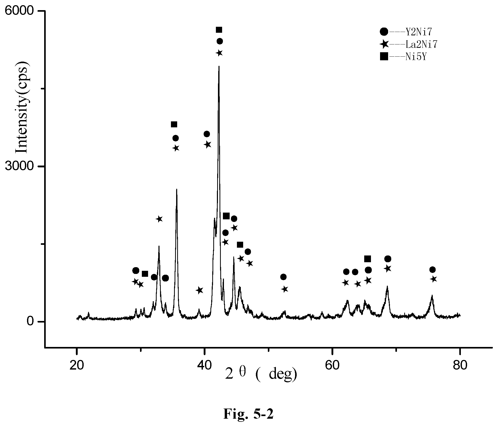
D00014
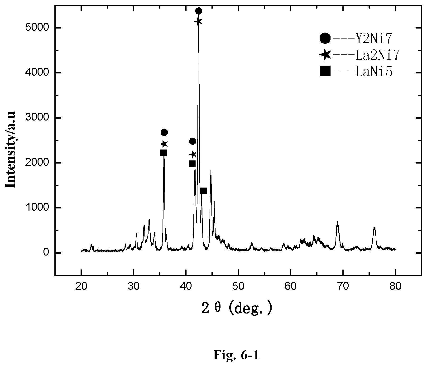
D00015
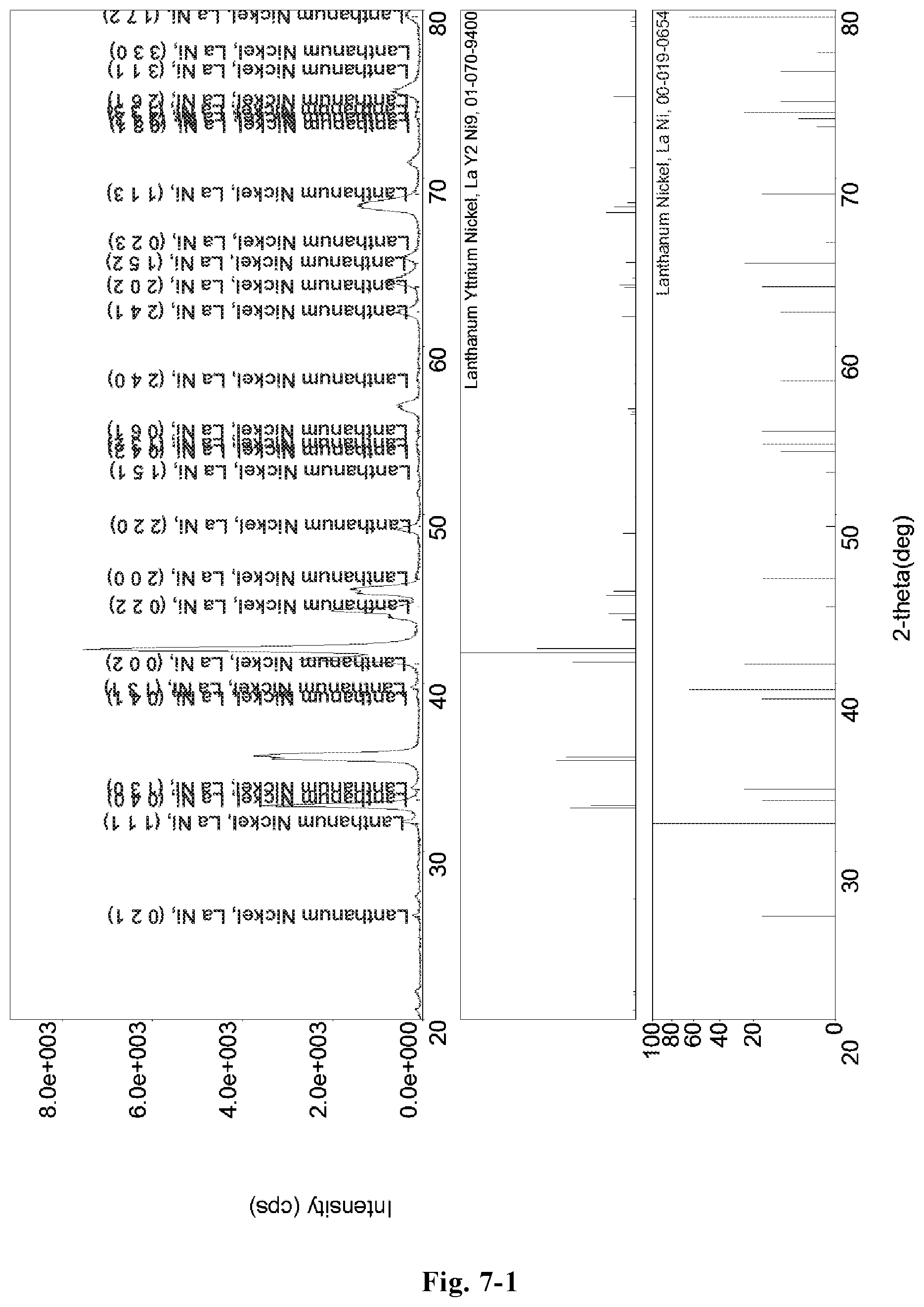
D00016
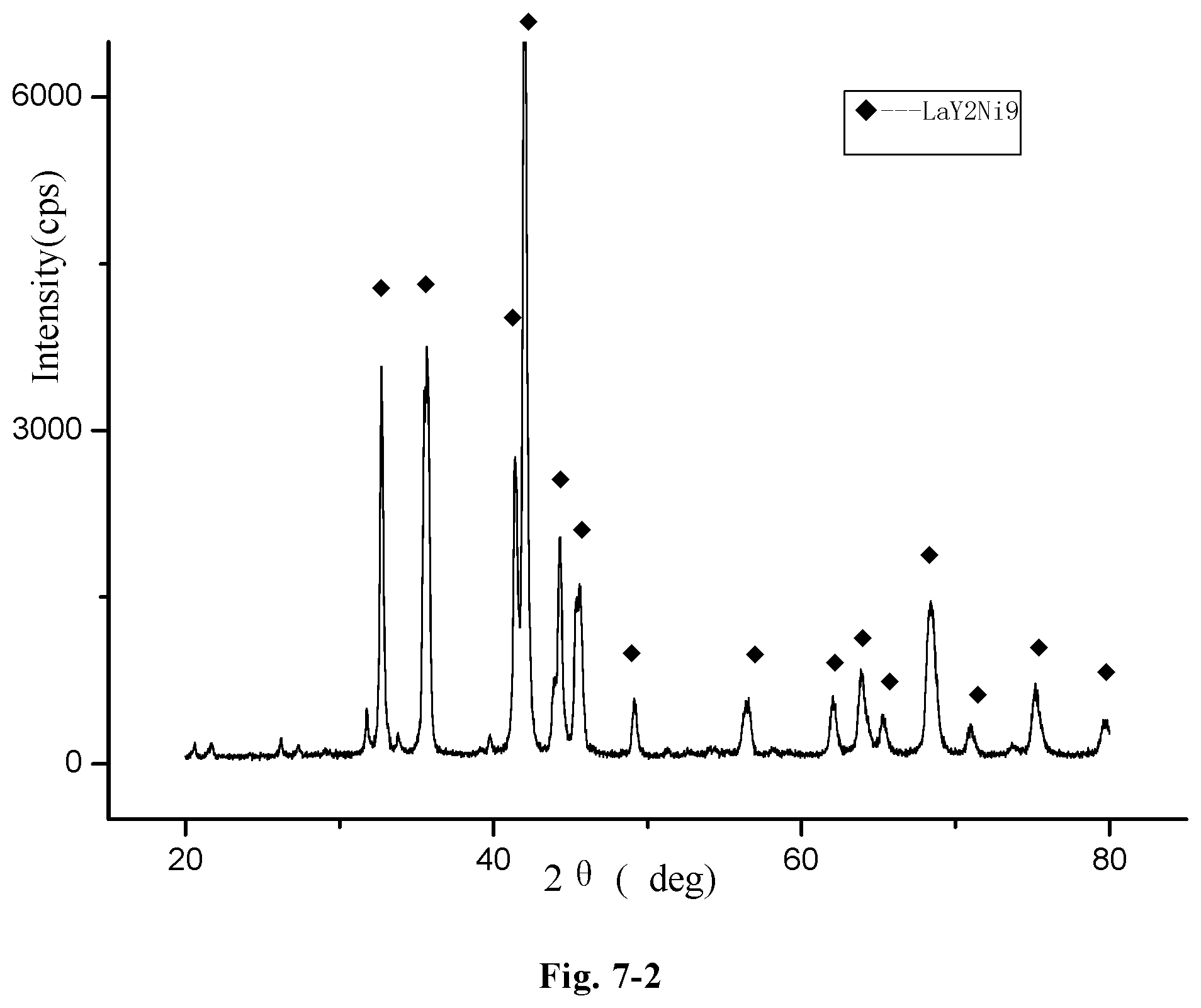
M00001

M00002

P00001

XML
uspto.report is an independent third-party trademark research tool that is not affiliated, endorsed, or sponsored by the United States Patent and Trademark Office (USPTO) or any other governmental organization. The information provided by uspto.report is based on publicly available data at the time of writing and is intended for informational purposes only.
While we strive to provide accurate and up-to-date information, we do not guarantee the accuracy, completeness, reliability, or suitability of the information displayed on this site. The use of this site is at your own risk. Any reliance you place on such information is therefore strictly at your own risk.
All official trademark data, including owner information, should be verified by visiting the official USPTO website at www.uspto.gov. This site is not intended to replace professional legal advice and should not be used as a substitute for consulting with a legal professional who is knowledgeable about trademark law.