Query task processing based on memory allocation and performance criteria
Teodorescu , et al. Feb
U.S. patent number 10,565,206 [Application Number 15/351,429] was granted by the patent office on 2020-02-18 for query task processing based on memory allocation and performance criteria. This patent grant is currently assigned to Deephaven Data Labs LLC. The grantee listed for this patent is Deephaven Data Labs LLC. Invention is credited to Ryan Caudy, David R. Kent, IV, Radu Teodorescu, Charles Wright.


View All Diagrams
| United States Patent | 10,565,206 |
| Teodorescu , et al. | February 18, 2020 |
| **Please see images for: ( Certificate of Correction ) ** |
Query task processing based on memory allocation and performance criteria
Abstract
Described are methods, systems and computer readable media for query task operations based on memory allocation and performance criteria.
| Inventors: | Teodorescu; Radu (New York, NY), Caudy; Ryan (New York, NY), Kent, IV; David R. (Colorado Springs, CO), Wright; Charles (Cortlandt Manor, NY) | ||||||||||
|---|---|---|---|---|---|---|---|---|---|---|---|
| Applicant: |
|
||||||||||
| Assignee: | Deephaven Data Labs LLC
(Plymouth, MN) |
||||||||||
| Family ID: | 57248327 | ||||||||||
| Appl. No.: | 15/351,429 | ||||||||||
| Filed: | November 14, 2016 |
Prior Publication Data
| Document Identifier | Publication Date | |
|---|---|---|
| US 20180137175 A1 | May 17, 2018 | |
Related U.S. Patent Documents
| Application Number | Filing Date | Patent Number | Issue Date | ||
|---|---|---|---|---|---|
| 15154991 | Apr 4, 2017 | 9613109 | |||
| 62161813 | May 14, 2015 | ||||
| Current U.S. Class: | 1/1 |
| Current CPC Class: | G06F 3/0483 (20130101); G06F 8/60 (20130101); G06F 11/1451 (20130101); G06F 16/24534 (20190101); G06F 16/285 (20190101); G06F 40/117 (20200101); G06F 40/216 (20200101); G06F 3/04847 (20130101); G06F 3/0485 (20130101); G06F 16/2379 (20190101); G06F 16/245 (20190101); G06F 16/9535 (20190101); G06F 16/144 (20190101); G06F 16/2453 (20190101); G06F 16/2457 (20190101); H04L 12/18 (20130101); G06F 16/113 (20190101); G06F 16/242 (20190101); G06F 16/2428 (20190101); H04L 63/102 (20130101); G06F 3/0481 (20130101); G06F 16/2455 (20190101); G06F 3/0605 (20130101); G06F 16/24575 (20190101); G06F 16/9024 (20190101); G06F 16/9566 (20190101); G06F 40/183 (20200101); H04L 67/1002 (20130101); G06F 3/067 (20130101); G06F 12/084 (20130101); G06F 16/24537 (20190101); G06F 16/2264 (20190101); G06F 16/2272 (20190101); G06F 16/2358 (20190101); G06F 3/04895 (20130101); G06F 3/0656 (20130101); G06F 16/278 (20190101); G06F 11/1464 (20130101); G06F 16/254 (20190101); H04L 51/12 (20130101); G06F 8/427 (20130101); G06F 16/2365 (20190101); G06F 16/951 (20190101); G06F 16/2228 (20190101); G06F 16/2255 (20190101); H04L 67/28 (20130101); H04L 67/42 (20130101); G06F 11/1469 (20130101); G06F 16/2308 (20190101); G06F 16/2372 (20190101); G06F 16/2246 (20190101); G06F 16/9574 (20190101); G06F 40/166 (20200101); H04L 69/16 (20130101); G06F 16/23 (20190101); G06F 16/24553 (20190101); G06F 16/27 (20190101); G06F 21/6209 (20130101); G06F 40/174 (20200101); G06F 16/162 (20190101); G06F 16/2237 (20190101); H04L 63/101 (20130101); G06F 16/24561 (20190101); G06F 16/248 (20190101); G06F 15/17331 (20130101); G06F 16/221 (20190101); G06F 21/00 (20130101); H04L 67/2842 (20130101); G06F 40/18 (20200101); H04L 67/2833 (20130101); G06F 16/215 (20190101); G06F 16/24535 (20190101); G06F 16/2456 (20190101); H04L 67/141 (20130101); G06F 16/22 (20190101); G06F 16/24539 (20190101); G06F 40/134 (20200101); G06F 12/0261 (20130101); H04L 51/046 (20130101); G06F 12/1483 (20130101); G06F 8/30 (20130101); G06F 16/907 (20190101); H04L 67/34 (20130101); G06F 3/0482 (20130101); G06F 8/41 (20130101); G06F 40/177 (20200101); H04L 61/2069 (20130101); G06F 16/2282 (20190101); G06F 40/274 (20200101); G06F 16/2291 (20190101); G06F 2201/805 (20130101); G06F 2201/84 (20130101); G06F 2212/154 (20130101); G06F 2212/163 (20130101); G06F 2212/60 (20130101); G06F 17/40 (20130101); H04L 67/2847 (20130101); G06F 2212/1052 (20130101) |
| Current International Class: | G06F 16/22 (20190101); G06F 16/2455 (20190101) |
| Field of Search: | ;707/720 |
References Cited [Referenced By]
U.S. Patent Documents
| 5335202 | August 1994 | Manning et al. |
| 5452434 | September 1995 | Macdonald |
| 5469567 | November 1995 | Okada |
| 5504885 | April 1996 | Alashqur |
| 5530939 | June 1996 | Mansfield et al. |
| 5568632 | October 1996 | Nelson |
| 5673369 | September 1997 | Kim |
| 5701461 | December 1997 | Dalal et al. |
| 5701467 | December 1997 | Freeston |
| 5764953 | June 1998 | Collins et al. |
| 5787411 | July 1998 | Groff et al. |
| 5787428 | July 1998 | Hart |
| 5806059 | September 1998 | Tsuchida et al. |
| 5808911 | September 1998 | Tucker et al. |
| 5859972 | January 1999 | Subramaniam et al. |
| 5873075 | February 1999 | Cochrane et al. |
| 5875334 | February 1999 | Chow et al. |
| 5878415 | March 1999 | Olds |
| 5890167 | March 1999 | Bridge et al. |
| 5899990 | May 1999 | Maritzen et al. |
| 5920860 | July 1999 | Maheshwari et al. |
| 5943672 | August 1999 | Yoshida |
| 5960087 | September 1999 | Tribble et al. |
| 5991810 | November 1999 | Shapiro et al. |
| 5999918 | December 1999 | Williams et al. |
| 6006220 | December 1999 | Haderle et al. |
| 6032144 | February 2000 | Srivastava et al. |
| 6032148 | February 2000 | Wilkes |
| 6038563 | March 2000 | Bapat et al. |
| 6058394 | May 2000 | Bakow et al. |
| 6061684 | May 2000 | Glasser et al. |
| 6138112 | October 2000 | Slutz |
| 6160548 | December 2000 | Lea |
| 6253195 | June 2001 | Hudis |
| 6266669 | July 2001 | Brodersen et al. |
| 6289357 | September 2001 | Parker |
| 6292803 | September 2001 | Richardson et al. |
| 6304876 | October 2001 | Isip |
| 6317728 | November 2001 | Kane |
| 6327702 | December 2001 | Sauntry et al. |
| 6336114 | January 2002 | Garrison |
| 6353819 | March 2002 | Edwards et al. |
| 6367068 | April 2002 | Vaidyanathan et al. |
| 6389414 | May 2002 | Delo et al. |
| 6389462 | May 2002 | Cohen et al. |
| 6397206 | May 2002 | Hill |
| 6438537 | August 2002 | Netz et al. |
| 6446069 | September 2002 | Yaung et al. |
| 6460037 | October 2002 | Weiss et al. |
| 6473750 | October 2002 | Petculescu et al. |
| 6487552 | November 2002 | Lei et al. |
| 6496833 | December 2002 | Goldberg et al. |
| 6505189 | January 2003 | Au et al. |
| 6505241 | January 2003 | Pitts |
| 6510551 | January 2003 | Miller |
| 6519604 | February 2003 | Acharya |
| 6530075 | March 2003 | Beadle et al. |
| 6538651 | March 2003 | Hayman et al. |
| 6546402 | April 2003 | Beyer et al. |
| 6553375 | April 2003 | Huang et al. |
| 6584474 | June 2003 | Pereira |
| 6604104 | August 2003 | Smith |
| 6618720 | September 2003 | Au et al. |
| 6631374 | October 2003 | Klein et al. |
| 6640234 | October 2003 | Coffen et al. |
| 6697880 | February 2004 | Dougherty |
| 6701415 | March 2004 | Hendren |
| 6714962 | March 2004 | Helland et al. |
| 6725243 | April 2004 | Snapp |
| 6732100 | May 2004 | Brodersen et al. |
| 6745332 | June 2004 | Wong et al. |
| 6748374 | June 2004 | Madan et al. |
| 6748455 | June 2004 | Hinson et al. |
| 6760719 | July 2004 | Hanson et al. |
| 6775660 | August 2004 | Lin et al. |
| 6785668 | August 2004 | Polo et al. |
| 6795851 | September 2004 | Noy |
| 6801908 | October 2004 | Fuloria |
| 6816855 | November 2004 | Hartel et al. |
| 6820082 | November 2004 | Cook et al. |
| 6829620 | December 2004 | Michael et al. |
| 6832229 | December 2004 | Reed |
| 6851088 | February 2005 | Conner et al. |
| 6882994 | April 2005 | Yoshimura et al. |
| 6925472 | August 2005 | Kong |
| 6934717 | August 2005 | James |
| 6947928 | September 2005 | Dettinger et al. |
| 6983291 | January 2006 | Cochrane et al. |
| 6985895 | January 2006 | Witkowski et al. |
| 6985899 | January 2006 | Chan et al. |
| 6985904 | January 2006 | Kaluskar et al. |
| 7020649 | March 2006 | Cochrane et al. |
| 7024414 | April 2006 | Sah et al. |
| 7031962 | April 2006 | Moses |
| 7047484 | May 2006 | Becker |
| 7058657 | June 2006 | Berno |
| 7089228 | August 2006 | Arnold et al. |
| 7089245 | August 2006 | George et al. |
| 7096216 | August 2006 | Anonsen |
| 7099927 | August 2006 | Cudd et al. |
| 7103608 | September 2006 | Ozbutun et al. |
| 7110997 | September 2006 | Turkel et al. |
| 7127462 | October 2006 | Hiraga et al. |
| 7146357 | December 2006 | Suzuki et al. |
| 7149742 | December 2006 | Eastham et al. |
| 7167870 | January 2007 | Avvari et al. |
| 7171469 | January 2007 | Ackaouy et al. |
| 7174341 | February 2007 | Ghukasyan et al. |
| 7181686 | February 2007 | Bahrs |
| 7188105 | March 2007 | Dettinger et al. |
| 7200620 | April 2007 | Gupta |
| 7216115 | May 2007 | Walters et al. |
| 7216116 | May 2007 | Nilsson et al. |
| 7219302 | May 2007 | O'Shaughnessy et al. |
| 7225189 | May 2007 | McCormack et al. |
| 7254808 | August 2007 | Trappen et al. |
| 7257689 | August 2007 | Baird |
| 7272605 | September 2007 | Hinshaw et al. |
| 7308580 | December 2007 | Nelson et al. |
| 7316003 | January 2008 | Dulepet et al. |
| 7330969 | February 2008 | Harrison et al. |
| 7333941 | February 2008 | Choi |
| 7343585 | March 2008 | Lau et al. |
| 7350237 | March 2008 | Vogel et al. |
| 7380242 | May 2008 | Alaluf |
| 7401088 | July 2008 | Chintakayala et al. |
| 7426521 | September 2008 | Harter |
| 7430549 | September 2008 | Zane et al. |
| 7433863 | October 2008 | Zane et al. |
| 7447865 | November 2008 | Uppala et al. |
| 7478094 | January 2009 | Ho et al. |
| 7484096 | January 2009 | Garg et al. |
| 7493311 | February 2009 | Cutsinger et al. |
| 7506055 | March 2009 | McClain et al. |
| 7529734 | May 2009 | Dirisala |
| 7529750 | May 2009 | Bair |
| 7542958 | June 2009 | Warren et al. |
| 7552223 | June 2009 | Ackaouy et al. |
| 7596550 | September 2009 | Mordvinov |
| 7610351 | October 2009 | Gollapudi et al. |
| 7620687 | November 2009 | Chen et al. |
| 7624126 | November 2009 | Pizzo et al. |
| 7627603 | December 2009 | Rosenblum et al. |
| 7661141 | February 2010 | Dutta et al. |
| 7664778 | February 2010 | Yagoub et al. |
| 7672275 | March 2010 | Yajnik et al. |
| 7680782 | March 2010 | Chen et al. |
| 7711716 | May 2010 | Stonecipher |
| 7711740 | May 2010 | Minore et al. |
| 7711788 | May 2010 | Ran et al. |
| 7747640 | June 2010 | Dettinger et al. |
| 7761444 | July 2010 | Zhang et al. |
| 7797356 | September 2010 | Iyer et al. |
| 7827204 | November 2010 | Heinzel et al. |
| 7827403 | November 2010 | Wong et al. |
| 7827523 | November 2010 | Ahmed et al. |
| 7882121 | February 2011 | Bruno et al. |
| 7882132 | February 2011 | Ghatare |
| 7895191 | February 2011 | Colossi |
| 7904487 | March 2011 | Ghatare |
| 7908259 | March 2011 | Branscome et al. |
| 7908266 | March 2011 | Zeringue et al. |
| 7930412 | April 2011 | Yeap et al. |
| 7966311 | June 2011 | Haase |
| 7966312 | June 2011 | Nolan et al. |
| 7966343 | June 2011 | Yang et al. |
| 7970777 | June 2011 | Saxena et al. |
| 7979431 | July 2011 | Qazi et al. |
| 7984043 | July 2011 | Waas |
| 8019795 | September 2011 | Anderson et al. |
| 8027293 | September 2011 | Spaur et al. |
| 8032525 | October 2011 | Bowers et al. |
| 8037542 | October 2011 | Taylor et al. |
| 8046394 | October 2011 | Shatdal |
| 8046749 | October 2011 | Owen et al. |
| 8055672 | November 2011 | Djugash et al. |
| 8060484 | November 2011 | Bandera et al. |
| 8171018 | May 2012 | Zane et al. |
| 8180789 | May 2012 | Wasserman et al. |
| 8196121 | June 2012 | Peshansky et al. |
| 8209356 | June 2012 | Roesler |
| 8286189 | October 2012 | Kukreja et al. |
| 8321833 | November 2012 | Langworthy et al. |
| 8332435 | December 2012 | Ballard et al. |
| 8359305 | January 2013 | Burke et al. |
| 8375127 | February 2013 | Lita |
| 8380757 | February 2013 | Bailey et al. |
| 8418142 | April 2013 | Ao et al. |
| 8433701 | April 2013 | Sargeant et al. |
| 8458218 | June 2013 | Wildermuth |
| 8473897 | June 2013 | Box et al. |
| 8478713 | July 2013 | Cotner et al. |
| 8515942 | August 2013 | Marum et al. |
| 8543620 | September 2013 | Ching |
| 8553028 | October 2013 | Urbach |
| 8555263 | October 2013 | Allen et al. |
| 8560502 | October 2013 | Vora |
| 8595151 | November 2013 | Hao et al. |
| 8601016 | December 2013 | Briggs et al. |
| 8621424 | December 2013 | Kejariwal |
| 8631034 | January 2014 | Peloski |
| 8635251 | January 2014 | Chan |
| 8650182 | February 2014 | Murthy |
| 8660869 | February 2014 | MacIntyre et al. |
| 8676863 | March 2014 | Connell et al. |
| 8683488 | March 2014 | Kukreja et al. |
| 8713518 | April 2014 | Pointer et al. |
| 8719252 | May 2014 | Miranker et al. |
| 8725707 | May 2014 | Chen et al. |
| 8726254 | May 2014 | Rohde et al. |
| 8745014 | June 2014 | Travis |
| 8745510 | June 2014 | D'Alo' et al. |
| 8751823 | June 2014 | Myles et al. |
| 8768961 | July 2014 | Krishnamurthy |
| 8788254 | July 2014 | Peloski |
| 8793243 | July 2014 | Weyerhaeuser et al. |
| 8805875 | August 2014 | Bawcom |
| 8805947 | August 2014 | Kuzkin et al. |
| 8806133 | August 2014 | Hay et al. |
| 8812625 | August 2014 | Chitilian et al. |
| 8838656 | September 2014 | Cheriton |
| 8855999 | October 2014 | Elliot |
| 8863156 | October 2014 | Lepanto et al. |
| 8874512 | October 2014 | Jin et al. |
| 8880569 | November 2014 | Draper et al. |
| 8880787 | November 2014 | Kimmel et al. |
| 8881121 | November 2014 | Ali |
| 8886631 | November 2014 | Abadi et al. |
| 8903717 | December 2014 | Elliot |
| 8903842 | December 2014 | Bloesch et al. |
| 8922579 | December 2014 | Mi et al. |
| 8924384 | December 2014 | Driesen et al. |
| 8930892 | January 2015 | Pointer et al. |
| 8954418 | February 2015 | Faerber et al. |
| 8959495 | February 2015 | Chafi et al. |
| 8996864 | March 2015 | Maigne et al. |
| 9031930 | May 2015 | Valentin |
| 9077611 | July 2015 | Cordray et al. |
| 9122765 | September 2015 | Chen |
| 9177079 | November 2015 | Ramachandran |
| 9195712 | November 2015 | Freedman et al. |
| 9298768 | March 2016 | Varakin et al. |
| 9311357 | April 2016 | Ramesh et al. |
| 9372671 | June 2016 | Balan et al. |
| 9384184 | July 2016 | Cervantes et al. |
| 9477702 | October 2016 | Ramachandran |
| 9612959 | April 2017 | Caudy et al. |
| 9613018 | April 2017 | Zeldis et al. |
| 9613109 | April 2017 | Wright et al. |
| 9619210 | April 2017 | Kent et al. |
| 9633060 | April 2017 | Caudy et al. |
| 9639570 | May 2017 | Wright et al. |
| 9672238 | June 2017 | Wright et al. |
| 9679006 | June 2017 | Wright et al. |
| 9690821 | June 2017 | Wright et al. |
| 9710511 | July 2017 | Wright et al. |
| 9760591 | September 2017 | Caudy et al. |
| 9805084 | October 2017 | Wright et al. |
| 9832068 | November 2017 | McSherry et al. |
| 9836494 | December 2017 | Caudy et al. |
| 9836495 | December 2017 | Wright |
| 9886469 | February 2018 | Kent et al. |
| 9898496 | February 2018 | Caudy et al. |
| 9934266 | April 2018 | Wright et al. |
| 10002153 | June 2018 | Teodorescu et al. |
| 10002154 | June 2018 | Kent, IV |
| 10002155 | June 2018 | Caudy et al. |
| 10003673 | June 2018 | Caudy et al. |
| 10019138 | July 2018 | Zeldis et al. |
| 10069943 | September 2018 | Teodorescu et al. |
| 2002/0002576 | January 2002 | Wollrath et al. |
| 2002/0007331 | January 2002 | Lo et al. |
| 2002/0054587 | May 2002 | Baker et al. |
| 2002/0065981 | May 2002 | Jenne et al. |
| 2002/0129168 | September 2002 | Kanai et al. |
| 2002/0156722 | October 2002 | Greenwood |
| 2003/0004952 | January 2003 | Nixon et al. |
| 2003/0061216 | March 2003 | Moses |
| 2003/0074400 | April 2003 | Brooks et al. |
| 2003/0110416 | June 2003 | Morrison et al. |
| 2003/0167261 | September 2003 | Grust et al. |
| 2003/0182261 | September 2003 | Patterson |
| 2003/0208484 | November 2003 | Chang et al. |
| 2003/0208505 | November 2003 | Mullins et al. |
| 2003/0233632 | December 2003 | Aigen et al. |
| 2004/0002961 | January 2004 | Dettinger et al. |
| 2004/0015566 | January 2004 | Anderson et al. |
| 2004/0076155 | April 2004 | Yajnik et al. |
| 2004/0111492 | June 2004 | Nakahara et al. |
| 2004/0148630 | July 2004 | Choi |
| 2004/0186813 | September 2004 | Tedesco et al. |
| 2004/0216150 | October 2004 | Scheifler et al. |
| 2004/0220923 | November 2004 | Mica |
| 2004/0254876 | December 2004 | Coval et al. |
| 2005/0015490 | January 2005 | Saare et al. |
| 2005/0060693 | March 2005 | Robison et al. |
| 2005/0097447 | May 2005 | Serra et al. |
| 2005/0102284 | May 2005 | Srinivasan et al. |
| 2005/0102636 | May 2005 | McKeon et al. |
| 2005/0131893 | June 2005 | Glan |
| 2005/0132384 | June 2005 | Morrison et al. |
| 2005/0138624 | June 2005 | Morrison et al. |
| 2005/0144189 | June 2005 | Edwards et al. |
| 2005/0165866 | July 2005 | Bohannon et al. |
| 2005/0198001 | September 2005 | Cunningham et al. |
| 2005/0228828 | October 2005 | Chandrasekar |
| 2006/0059253 | March 2006 | Goodman et al. |
| 2006/0074901 | April 2006 | Pirahesh et al. |
| 2006/0085490 | April 2006 | Baron et al. |
| 2006/0100989 | May 2006 | Chinchwadkar et al. |
| 2006/0101019 | May 2006 | Nelson et al. |
| 2006/0116983 | June 2006 | Dettinger et al. |
| 2006/0116999 | June 2006 | Dettinger et al. |
| 2006/0131383 | June 2006 | Battagin |
| 2006/0136361 | June 2006 | Peri et al. |
| 2006/0173693 | August 2006 | Arazi et al. |
| 2006/0195460 | August 2006 | Nori et al. |
| 2006/0212847 | September 2006 | Tarditi et al. |
| 2006/0218123 | September 2006 | Chowdhuri et al. |
| 2006/0218200 | September 2006 | Factor et al. |
| 2006/0230016 | October 2006 | Cunningham et al. |
| 2006/0253311 | November 2006 | Yin et al. |
| 2006/0271510 | November 2006 | Harward et al. |
| 2006/0277162 | December 2006 | Smith |
| 2007/0011211 | January 2007 | Reeves et al. |
| 2007/0027884 | February 2007 | Heger et al. |
| 2007/0033518 | February 2007 | Kenna et al. |
| 2007/0073765 | March 2007 | Chen |
| 2007/0101252 | May 2007 | Chamberlain et al. |
| 2007/0113014 | May 2007 | Manolov |
| 2007/0116287 | May 2007 | Rasizade et al. |
| 2007/0169003 | July 2007 | Branda et al. |
| 2007/0198479 | August 2007 | Cai et al. |
| 2007/0256060 | November 2007 | Ryu et al. |
| 2007/0258508 | November 2007 | Werb et al. |
| 2007/0271280 | November 2007 | Chandasekaran |
| 2007/0294217 | December 2007 | Chen et al. |
| 2007/0299822 | December 2007 | Jopp et al. |
| 2008/0022136 | January 2008 | Mattsson et al. |
| 2008/0033907 | February 2008 | Woehler et al. |
| 2008/0034084 | February 2008 | Pandya |
| 2008/0046804 | February 2008 | Rui et al. |
| 2008/0072150 | March 2008 | Chan et al. |
| 2008/0097748 | April 2008 | Haley |
| 2008/0120283 | May 2008 | Liu et al. |
| 2008/0155565 | June 2008 | Poduri |
| 2008/0168135 | July 2008 | Redlich et al. |
| 2008/0172639 | July 2008 | Keysar et al. |
| 2008/0235238 | September 2008 | Jalobeanu et al. |
| 2008/0263179 | October 2008 | Buttner et al. |
| 2008/0276241 | November 2008 | Bajpai et al. |
| 2008/0319951 | December 2008 | Ueno et al. |
| 2009/0019029 | January 2009 | Tommaney et al. |
| 2009/0022095 | January 2009 | Spaur et al. |
| 2009/0024615 | January 2009 | Pedro et al. |
| 2009/0037391 | February 2009 | Agrawal et al. |
| 2009/0037500 | February 2009 | Kirshenbaum |
| 2009/0055370 | February 2009 | Dagum et al. |
| 2009/0083215 | March 2009 | Burger |
| 2009/0089312 | April 2009 | Chi et al. |
| 2009/0248902 | October 2009 | Blue |
| 2009/0254516 | October 2009 | Meiyyappan et al. |
| 2009/0271472 | October 2009 | Scheifler et al. |
| 2009/0300770 | December 2009 | Rowney et al. |
| 2009/0319058 | December 2009 | Rovaglio et al. |
| 2009/0319484 | December 2009 | Golbandi et al. |
| 2009/0327242 | December 2009 | Brown et al. |
| 2010/0023952 | January 2010 | Sandoval et al. |
| 2010/0036801 | February 2010 | Pirvali et al. |
| 2010/0042587 | February 2010 | Johnson et al. |
| 2010/0047760 | February 2010 | Best et al. |
| 2010/0049715 | February 2010 | Jacobsen et al. |
| 2010/0070721 | March 2010 | Pugh et al. |
| 2010/0114890 | May 2010 | Hagar et al. |
| 2010/0161555 | June 2010 | Nica et al. |
| 2010/0186082 | July 2010 | Ladki et al. |
| 2010/0199161 | August 2010 | Aureglia et al. |
| 2010/0205017 | August 2010 | Sichelman et al. |
| 2010/0205351 | August 2010 | Wiener et al. |
| 2010/0281005 | November 2010 | Carlin et al. |
| 2010/0281071 | November 2010 | Ben-Zvi et al. |
| 2011/0126110 | May 2011 | Vilke et al. |
| 2011/0126154 | May 2011 | Boehler et al. |
| 2011/0153603 | June 2011 | Adiba et al. |
| 2011/0161378 | June 2011 | Williamson |
| 2011/0167020 | July 2011 | Yang et al. |
| 2011/0178984 | July 2011 | Talius et al. |
| 2011/0194563 | August 2011 | Shen et al. |
| 2011/0219020 | September 2011 | Oks et al. |
| 2011/0314019 | December 2011 | Peris |
| 2012/0110030 | May 2012 | Pomponio |
| 2012/0144234 | June 2012 | Clark et al. |
| 2012/0159303 | June 2012 | Friedrich et al. |
| 2012/0191446 | July 2012 | Binsztok et al. |
| 2012/0192096 | July 2012 | Bowman et al. |
| 2012/0197868 | August 2012 | Fauser et al. |
| 2012/0209886 | August 2012 | Henderson |
| 2012/0215741 | August 2012 | Poole et al. |
| 2012/0221528 | August 2012 | Renkes |
| 2012/0246052 | September 2012 | Taylor et al. |
| 2012/0254143 | October 2012 | Varma et al. |
| 2012/0259759 | October 2012 | Crist et al. |
| 2012/0296846 | November 2012 | Teeter |
| 2013/0041946 | February 2013 | Joel et al. |
| 2013/0080514 | March 2013 | Gupta et al. |
| 2013/0086107 | April 2013 | Genochio et al. |
| 2013/0166551 | June 2013 | Wong et al. |
| 2013/0166556 | June 2013 | Baeumges et al. |
| 2013/0173667 | July 2013 | Soderberg et al. |
| 2013/0179460 | July 2013 | Cervantes et al. |
| 2013/0185619 | July 2013 | Ludwig |
| 2013/0191370 | July 2013 | Chen et al. |
| 2013/0198232 | August 2013 | Shamgunov et al. |
| 2013/0226959 | August 2013 | Dittrich et al. |
| 2013/0246560 | September 2013 | Feng et al. |
| 2013/0263123 | October 2013 | Zhou et al. |
| 2013/0290243 | October 2013 | Hazel et al. |
| 2013/0304725 | November 2013 | Nee et al. |
| 2013/0304744 | November 2013 | McSherry et al. |
| 2013/0311352 | November 2013 | Kayanuma et al. |
| 2013/0311488 | November 2013 | Erdogan et al. |
| 2013/0318129 | November 2013 | Vingralek et al. |
| 2013/0346365 | December 2013 | Kan et al. |
| 2014/0019494 | January 2014 | Tang |
| 2014/0026121 | January 2014 | Jackson et al. |
| 2014/0040203 | February 2014 | Lu et al. |
| 2014/0046638 | February 2014 | Peloski |
| 2014/0059646 | February 2014 | Hannel et al. |
| 2014/0082724 | March 2014 | Pearson et al. |
| 2014/0136521 | May 2014 | Pappas |
| 2014/0143123 | May 2014 | Banke et al. |
| 2014/0149997 | May 2014 | Kukreja et al. |
| 2014/0156618 | June 2014 | Castellano |
| 2014/0173023 | June 2014 | Varney et al. |
| 2014/0181036 | June 2014 | Dhamankar et al. |
| 2014/0181081 | June 2014 | Veldhuizen |
| 2014/0188924 | July 2014 | Ma et al. |
| 2014/0195558 | July 2014 | Murthy et al. |
| 2014/0201194 | July 2014 | Reddy et al. |
| 2014/0215446 | July 2014 | Araya et al. |
| 2014/0222768 | August 2014 | Rambo et al. |
| 2014/0229506 | August 2014 | Lee |
| 2014/0229874 | August 2014 | Strauss |
| 2014/0244687 | August 2014 | Shmueli et al. |
| 2014/0279810 | September 2014 | Mann et al. |
| 2014/0280522 | September 2014 | Watte |
| 2014/0282227 | September 2014 | Nixon et al. |
| 2014/0282444 | September 2014 | Araya et al. |
| 2014/0282540 | September 2014 | Bonnet et al. |
| 2014/0289700 | September 2014 | Srinivasaraghavan |
| 2014/0292765 | October 2014 | Maruyama et al. |
| 2014/0297611 | October 2014 | Abbour et al. |
| 2014/0317084 | October 2014 | Chaudhry et al. |
| 2014/0324821 | October 2014 | Meiyyappan et al. |
| 2014/0330700 | November 2014 | Studnitzer et al. |
| 2014/0330807 | November 2014 | Weyerhaeuser et al. |
| 2014/0344186 | November 2014 | Nadler |
| 2014/0344391 | November 2014 | Varney et al. |
| 2014/0358892 | December 2014 | Nizami et al. |
| 2014/0359574 | December 2014 | Beckwith et al. |
| 2014/0372482 | December 2014 | Martin et al. |
| 2014/0380051 | December 2014 | Edward et al. |
| 2015/0019516 | January 2015 | Wein et al. |
| 2015/0026155 | January 2015 | Martin |
| 2015/0032789 | January 2015 | Nguyen et al. |
| 2015/0067640 | March 2015 | Booker et al. |
| 2015/0074066 | March 2015 | Li et al. |
| 2015/0082218 | March 2015 | Affoneh et al. |
| 2015/0088894 | March 2015 | Czarlinska et al. |
| 2015/0095381 | April 2015 | Chen et al. |
| 2015/0120261 | April 2015 | Giannacopoulos et al. |
| 2015/0127599 | May 2015 | Schiebeler |
| 2015/0154262 | June 2015 | Yang et al. |
| 2015/0172117 | June 2015 | Dolinsky et al. |
| 2015/0188778 | July 2015 | Asayag et al. |
| 2015/0205588 | July 2015 | Bates et al. |
| 2015/0205589 | July 2015 | Dally |
| 2015/0254298 | September 2015 | Bourbonnais et al. |
| 2015/0304182 | October 2015 | Brodsky et al. |
| 2015/0317359 | November 2015 | Tran et al. |
| 2015/0356157 | December 2015 | Anderson et al. |
| 2016/0026383 | January 2016 | Lee et al. |
| 2016/0026442 | January 2016 | Chhaparia |
| 2016/0065670 | March 2016 | Kimmel et al. |
| 2016/0085772 | March 2016 | Vermeulen et al. |
| 2016/0092599 | March 2016 | Barsness et al. |
| 2016/0103897 | April 2016 | Nysewander |
| 2016/0125018 | May 2016 | Tomoda et al. |
| 2016/0147748 | May 2016 | Florendo |
| 2016/0171070 | June 2016 | Hrle et al. |
| 2016/0179754 | June 2016 | Borza et al. |
| 2016/0253294 | September 2016 | Allen et al. |
| 2016/0316038 | October 2016 | Jolfaei |
| 2016/0335281 | November 2016 | Teodorescu |
| 2016/0335304 | November 2016 | Teodorescu et al. |
| 2016/0335317 | November 2016 | Teodorescu et al. |
| 2016/0335323 | November 2016 | Teodorescu et al. |
| 2016/0335330 | November 2016 | Teodorescu et al. |
| 2016/0335361 | November 2016 | Teodorescu et al. |
| 2017/0032016 | February 2017 | Zinner |
| 2017/0161514 | June 2017 | Dettinger et al. |
| 2017/0177677 | June 2017 | Wright et al. |
| 2017/0185385 | June 2017 | Kent et al. |
| 2017/0192910 | July 2017 | Wright et al. |
| 2017/0206229 | July 2017 | Caudy et al. |
| 2017/0206256 | July 2017 | Tsirogiannis et al. |
| 2017/0235794 | August 2017 | Wright et al. |
| 2017/0235798 | August 2017 | Wright et al. |
| 2017/0249350 | August 2017 | Wright et al. |
| 2017/0270150 | September 2017 | Wright et al. |
| 2017/0316046 | November 2017 | Caudy et al. |
| 2017/0329740 | November 2017 | Crawford et al. |
| 2017/0357708 | December 2017 | Ramachandran |
| 2017/0359415 | December 2017 | Venkatraman et al. |
| 2018/0004796 | January 2018 | Kent et al. |
| 2018/0011891 | January 2018 | Wright et al. |
| 2018/0052879 | February 2018 | Wright |
| 2309462 | Dec 2000 | CA | |||
| 1406463 | Apr 2004 | EP | |||
| 1198769 | Jun 2008 | EP | |||
| 2199961 | Jun 2010 | EP | |||
| 2423816 | Feb 2012 | EP | |||
| 2743839 | Jun 2014 | EP | |||
| 2397906 | Aug 2004 | GB | |||
| 2421798 | Jun 2011 | RU | |||
| 2000000879 | Jan 2000 | WO | |||
| 2001079964 | Oct 2001 | WO | |||
| 2011120161 | Oct 2011 | WO | |||
| 2012136627 | Oct 2012 | WO | |||
| 2014026220 | Feb 2014 | WO | |||
| 2014143208 | Sep 2014 | WO | |||
| 2016183563 | Nov 2016 | WO | |||
Other References
|
Advisory Action dated Apr. 19, 2017, in U.S. Appl. No. 15/154,999. cited by applicant . Advisory Action dated Apr. 20, 2017, in U.S. Appl. No. 15/154,980. cited by applicant . Advisory Action dated Apr. 6, 2017, in U.S. Appl. No. 15/154,995. cited by applicant . Advisory Action dated Dec. 21, 2017, in U.S. Appl. No. 15/154,984. cited by applicant . Advisory Action dated Mar. 31, 2017, in U.S. Appl. No. 15/154,996. cited by applicant . Advisory Action dated May 3, 2017, in U.S. Appl. No. 15/154,993. cited by applicant . Breitbart, Update Propagation Protocols for Replicated Databases, SIGMOD '99 Philadelphia PA, 1999, pp. 97-108. cited by applicant . Corrected Notice of Allowability dated Aug. 9, 2017, in U.S. Appl. No. 15/154,980. cited by applicant . Corrected Notice of Allowability dated Jul. 31, 2017, in U.S. Appl. No. 15/154,999. cited by applicant . Corrected Notice of Allowability dated Mar. 10, 2017, in U.S. Appl. No. 15/154,979. cited by applicant . Corrected Notice of Allowability dated Oct. 26, 2017, in U.S. Appl. No. 15/610,162. cited by applicant . Decision on Pre-Appeal Conference Request dated Nov. 20, 2017, in U.S. Appl. No. 15/154,997. cited by applicant . Final Office Action dated Apr. 10, 2017, in U.S. Appl. No. 15/155,006. cited by applicant . Final Office Action dated Dec. 29, 2017, in U.S. Appl. No. 15/154,974. cited by applicant . Final Office Action dated Feb. 24, 2017, in U.S. Appl. No. 15/154,993. cited by applicant . Final Office Action dated Jul. 27, 2017, in U.S. Appl. No. 15/154,993. cited by applicant . Final Office Action dated Jun. 23, 2017, in U.S. Appl. No. 15/154,997. cited by applicant . Final Office Action dated Mar. 1, 2017, in U.S. Appl. No. 15/154,975. cited by applicant . Final Office Action dated Mar. 13, 2017, in U.S. Appl. No. 15/155,012. cited by applicant . Final Office Action dated Mar. 31, 2017, in U.S. Appl. No. 15/155,005. cited by applicant . Final Office Action dated May 15, 2017, in U.S. Appl. No. 15/155,010. cited by applicant . Final Office Action dated May 4, 2017, in U.S. Appl. No. 15/155,009. cited by applicant . Kramer, The Combining DAG: A Technique for Parallel Data Flow Analysis, IEEE Transactions on Parallel and Distributed Systems, vol. 5, No. 8, Aug. 1994, pp. 805-813. cited by applicant . Non-final Office Action dated Apr. 19, 2017, in U.S. Appl. No. 15/154,974. cited by applicant . Non-final Office Action dated Aug. 14, 2017, in U.S. Appl. No. 15/464,314. cited by applicant . Non-final Office Action dated Dec. 13, 2017, in U.S. Appl. No. 15/608,963. cited by applicant . Non-final Office Action dated Dec. 28, 2017, in U.S. Appl. No. 15/154,996. cited by applicant . Non-final Office Action dated Dec. 28, 2017, in U.S. Appl. No. 15/796,230. cited by applicant . Non-final Office Action dated Feb. 12, 2018, in U.S. Appl. No. 15/466,836. cited by applicant . Non-final Office Action dated Feb. 15, 2018, in U.S. Appl. No. 15/813,112. cited by applicant . Non-final Office Action dated Feb. 28, 2018, in U.S. Appl. No. 15/813,119. cited by applicant . Non-final Office Action dated Jan. 4, 2018, in U.S. Appl. No. 15/583,777. cited by applicant . Non-final Office Action dated Jul. 27, 2017, in U.S. Appl. No. 15/154,995. cited by applicant . Non-final Office Action dated Mar. 2, 2017, in U.S. Appl. No. 15/154,984. cited by applicant . Non-final Office Action dated Mar. 20, 2018, in U.S. Appl. No. 15/155,006. cited by applicant . Non-final Office Action dated Nov. 15, 2017, in U.S. Appl. No. 15/654,461. cited by applicant . Non-final Office Action dated Nov. 21, 2017, in U.S. Appl. No. 15/155,005. cited by applicant . Non-final Office Action dated Nov. 30, 2017, in U.S. Appl. No. 15/155,012. cited by applicant . Non-final Office Action dated Oct. 5, 2017, in U.S. Appl. No. 15/428,145. cited by applicant . Notice of Allowance dated Feb. 12, 2018, in U.S. Appl. No. 15/813,142. cited by applicant . Notice of Allowance dated Feb. 26, 2018, in U.S. Appl. No. 15/428,145. cited by applicant . Notice of Allowance dated Feb. 28, 2017, in U.S. Appl. No. 15/154,990. cited by applicant . Notice of Allowance dated Jul. 28, 2017, in U.S. Appl. No. 15/155,009. cited by applicant . Notice of Allowance dated Jun. 19, 2017, in U.S. Appl. No. 15/154,980. cited by applicant . Notice of Allowance dated Jun. 20, 2017, in U.S. Appl. No. 15/154,975. cited by applicant . Notice of Allowance dated Mar. 1, 2018, in U.S. Appl. No. 15/464,314. cited by applicant . Notice of Allowance dated Mar. 2, 2017, in U.S. Appl. No. 15/154,998. cited by applicant . Notice of Allowance dated Mar. 31, 2017, in U.S. Appl. No. 15/154,998. cited by applicant . Notice of Allowance dated May 10, 2017, in U.S. Appl. No. 15/154,988. cited by applicant . Notice of Allowance dated Nov. 17, 2017, in U.S. Appl. No. 15/154,993. cited by applicant . Final Office Action dated Aug. 10, 2018, in U.S. Appl. No. 15/796,230. cited by applicant . Final Office Action dated Aug. 2, 2018, in U.S. Appl. No. 15/154,996. cited by applicant . Final Office Action dated Aug. 28, 2018, in U.S. Appl. No. 15/813,119. cited by applicant . Final Office Action dated Jun. 18, 2018, in U.S. Appl. No. 15/155,005. cited by applicant . Final Office Action dated May 18, 2018, in U.S. Appl. No. 15/654,461. cited by applicant . Non-final Office Action dated Apr. 12, 2018, in U.S. Appl. No. 15/154,997. cited by applicant . Non-final Office Action dated Apr. 23, 2018, in U.S. Appl. No. 15/813,127. cited by applicant . Non-final Office Action dated Apr. 5, 2018, in U.S. Appl. No. 15/154,984. cited by applicant . Non-final Office Action dated Aug. 10, 2018, in U.S. Appl. No. 16/004,578. cited by applicant . Non-final Office Action dated Jun. 29, 2018, in U.S. Appl. No. 15/154,974. cited by applicant . Non-final Office Action dated Jun. 8, 2018, in U.S. Appl. No. 15/452,574. cited by applicant . Notice of Allowance dated Apr. 30, 2018, in U.S. Appl. No. 15/155,012. cited by applicant . Notice of Allowance dated Jul. 11, 2018, in U.S. Appl. No. 15/154,995. cited by applicant . Notice of Allowance dated May 4, 2018, in U.S. Appl. No. 15/897,547. cited by applicant . Notice of Allowance dated Sep. 11, 2018, in U.S. Appl. No. 15/608,963. cited by applicant . Hartle, Thom, Conditional Formatting in Excel using CQG's RTD Bate Function (2011), http://news.cqg.com/blogs/excel/2011/05/conditional-formatting-excel-usin- g-cqgs-rtd-bate-function (last visited Apr. 3, 2019). cited by applicant . Azbel, Maria, How to hide and group columns in Excel AbleBits (2014), https://www.ablebits.com/office-addins-blog/2014/08/06/excel-hide-columns- / (last visited Jan. 18, 2019). cited by applicant . Dodge, Mark & Craig Stinson, Microsoft Excel 2010 inside out (2011). cited by applicant . Cheusheve, Svetlana, Excel formulas for conditional formatting based on another cell AbleBits (2014), https://www.ablebits.com/office-addins-blog/2014/06/10/excel-conditional-- formatting-formulas/comment-page-6/ (last visited Jan. 14, 2019). cited by applicant . Notice of Allowance dated Oct. 6, 2017, in U.S. Appl. No. 15/610,162. cited by applicant . Sobell, Mark G. "A Practical Guide to Linux, Commands, Editors and Shell Programming." Third Edition, dated Sep. 14, 2012. Retrieved from: http://techbus.safaribooksonline.com/book/operating-systems-and-server-ad- ministration/linux/9780133085129. cited by applicant . Jellema, Lucas. "Implementing Cell Highlighting in JSF-based Rich Enterprise Apps (Part 1)", dated Nov. 2008. Retrieved from http://www.oracle.com/technetwork/articles/adf/jellema-adfcellhighlightin- g-087850.html (last accessed Jun. 16, 2016). cited by applicant . Lou, Yuan. "A Multi-Agent Decision Support System for Stock Trading", IEEE Network, Jan./Feb. 2002. Retreived from http://www.reading.ac.uk/AcaDepts/si/sisweb13/ais/papers/journal12-A%20mu- lti-agent%20Framework.pdf. cited by applicant . Mallet, "Relational Database Support for Spatio-Temporal Data", Technical Report TR 04-21, Sep. 2004, University of Alberta, Department of Computing Science. cited by applicant . Mariyappan, Balakrishnan. "10 Useful Linux Bash_Completion Complete Command Examples (Bash Command Line Completion on Steroids)", dated Dec. 2, 2013. Retrieved from http://www.thegeekstuff.com/2013/12/bash-completion-complete/ (last accessed Jun. 16, 2016). cited by applicant . Murray, Derek G. et al. "Naiad: a timely dataflow system." SOSP '13 Proceedings of the Twenty-Fourth ACM Symposium on Operating Systems Principles. pp. 439-455. Nov. 2013. cited by applicant . Non-final Office Action dated Aug. 12, 2016, in U.S. Appl. No. 15/155,001. cited by applicant . Non-final Office Action dated Aug. 16, 2016, in U.S. Appl. No. 15/154,993. cited by applicant . Non-final Office Action dated Aug. 19, 2016, in U.S. Appl. No. 15/154,991. cited by applicant . Non-final Office Action dated Aug. 25, 2016, in U.S. Appl. No. 15/154,980. cited by applicant . Non-final Office Action dated Aug. 26, 2016, in U.S. Appl. No. 15/154,995. cited by applicant . Non-final Office Action dated Aug. 8, 2016, in U.S. Appl. No. 15/154,983. cited by applicant . Non-final Office Action dated Aug. 8, 2016, in U.S. Appl. No. 15/154,985. cited by applicant . Non-final Office Action dated Feb. 8, 2017, in U.S. Appl. No. 15/154,997. cited by applicant . Non-final Office Action dated Nov. 17, 2016, in U.S. Appl. No. 15/154,999. cited by applicant . Non-final Office Action dated Oct. 13, 2016, in U.S. Appl. No. 15/155,009. cited by applicant . Non-final Office Action dated Oct. 27, 2016, in U.S. Appl. No. 15/155,006. cited by applicant . Non-final Office Action dated Oct. 7, 2016, in U.S. Appl. No. 15/154,998. cited by applicant . Non-final Office Action dated Sep. 1, 2016, in U.S. Appl. No. 15/154,979. cited by applicant . Non-final Office Action dated Sep. 1, 2016, in U.S. Appl. No. 15/155,011. cited by applicant . Non-final Office Action dated Sep. 1, 2016, in U.S. Appl. No. 15/155,012. cited by applicant . Non-final Office Action dated Sep. 14, 2016, in U.S. Appl. No. 15/154,984. cited by applicant . Non-final Office Action dated Sep. 16, 2016, in U.S. Appl. No. 15/154,988. cited by applicant . Non-final Office Action dated Sep. 22, 2016, in U.S. Appl. No. 15/154,987. cited by applicant . Non-final Office Action dated Sep. 26, 2016, in U.S. Appl. No. 15/155,005. cited by applicant . Non-final Office Action dated Sep. 29, 2016, in U.S. Appl. No. 15/154,990. cited by applicant . Non-final Office Action dated Sep. 8, 2016, in U.S. Appl. No. 15/154,975. cited by applicant . Non-final Office Action dated Sep. 9, 2016, in U.S. Appl. No. 15/154,996. cited by applicant . Non-final Office Action dated Sep. 9, 2016, in U.S. Appl. No. 15/155,010. cited by applicant . Notice of Allowance dated Dec. 19, 2016, in U.S. Appl. No. 15/155,001. cited by applicant . Notice of Allowance dated Dec. 22, 2016, in U.S. Appl. No. 15/155,011. cited by applicant . Notice of Allowance dated Dec. 7, 2016, in U.S. Appl. No. 15/154,985. cited by applicant . Notice of Allowance dated Feb. 1, 2017, in U.S. Appl. No. 15/154,988. cited by applicant . Notice of Allowance dated Feb. 14, 2017, in U.S. Appl. No. 15/154,979. cited by applicant . Notice of Allowance dated Jan. 30, 2017, in U.S. Appl. No. 15/154,987. cited by applicant . Notice of Allowance dated Nov. 17, 2016, in U.S. Appl. No. 15/154,991. cited by applicant . Notice of Allowance dated Nov. 21, 2016, in U.S. Appl. No. 15/154,983. cited by applicant . Notice of Allowance dated Nov. 8, 2016, in U.S. Appl. No. 15/155,007. cited by applicant . Notice of Allowance dated Oct. 11, 2016, in U.S. Appl. No. 15/155,007. cited by applicant . Notice of Allowance dated Oct. 21, 2016, in U.S. Appl. No. 15/154,999. cited by applicant . Palpanas, Themistoklis et al. "Incremental Maintenance for Non-Distributive Aggregate Functions", Proceedings of the 28th VLDB Conference, 2002. Retreived from http://www.vldb.org/conf/2002/S22P04.pdf. cited by applicant . PowerShell Team, Intellisense in Windows PowerShell ISE 3.0, dated Jun. 12, 2012, Windows PowerShell Blog, pp. 1-6 Retrieved: https://biogs.msdn.microsoft.com/powershell/2012/06/12/intellisense-in-wi- ndows-powershell-ise-3-0/. cited by applicant . Smith, Ian. "Guide to Using SQL: Computed and Automatic Columns." Rdb Jornal, dated Sep. 2008, retrieved Aug. 15, 2016, retrieved from the Internet <URL: http://www.oracle.com/technetwork/products/rdb/automatic-columns-132042.p- df>. cited by applicant . Wes McKinney & PyData Development Team. "pandas: powerful Python data analysis toolkit, Release 0.16.1" Dated May 11, 2015. Retrieved from: http://pandas.pydata.org/pandas-docs/version/0.16.1/index.html. cited by applicant . Wes McKinney & PyData Development Team. "pandas: powerful Python data analysis toolkit, Release 0.18.1" Dated May 3, 2016. Retrieved from: http://pandas.pydata.org/pandas-docs/version/0.18.1/index.html. cited by applicant . Wu, Buwen et al. "Scalable SPARQL Querying using Path Partitioning", 31st IEEE International Conference on Data Engineering (ICDE 2015), Seoul, Korea, Apr. 13-17, 2015. Retreived from http://imada.sdu.dk/.about.zhou/papers/icde2015.pdf. cited by applicant . Posey, Brien, "How to Combine PowerShell Cmdlets", Jun. 14, 2013 Redmond the Independent Voice of the Microsoft Community (Year: 2013). cited by applicant . "About Entering Commands in the Command Window", dated Dec. 16, 2015. Retrieved from https://knowledge.autodesk.com/support/autocad/learn-explore/caas/CloudHe- lp/cloudhelp/2016/ENU/AutoCAD-Core/files/GUID-BB0C3E79-66AF-4557-9140-D31B- 4CF3C9CF-htm.html (last accessed Jun. 16, 2016). cited by applicant . "Change Data Capture", Oracle Database Online Documentation 11g Release 1 (11.1), dated Apr. 5, 2016. Retreived from https://web.archive.org/web/20160405032625/http://docs.oracle.com/cd/B283- 59_01/server.111/b28313/cdc.htm. cited by applicant . "Chapter 24. Query access plans", Tuning Database Performance, DB2 Version 9.5 for Linux, UNIX, and Windows, pp. 301-462, dated Dec. 2010. Retreived from http://public.dhe.ibm.com/ps/products/db2/info/vr95/pdf/en_US/DB2Per- fTuneTroubleshoot-db2d3e953.pdf. cited by applicant . "GNU Emacs Manual", dated Apr. 15, 2016, pp. 43-47. Retrieved from https://web.archive.org/web/20160415175915/http://www.gnu.org/software/em- acs/manual/html_mono/emacs.html. cited by applicant . "Google Protocol RPC Library Overview", dated Apr. 27, 2016. Retrieved from https://cloud.google.com/appengine/docs/python/tools/protorpc/ (last accessed Jun. 16, 2016). cited by applicant . "IBM--What is HBase?", dated Sep. 6, 2015. Retrieved from https://web.archive.org/web/20150906022050/http://www-01.ibm.com/software- /data/infosphere/hadoop/hbase/. cited by applicant . "IBM Informix TimeSeries data management", dated Jan. 18, 2016. Retrieved from https://web.archive.org/web/20160118072141/http://www-01.ibm.com/sof- tware/data/informix/timeseries/. cited by applicant . "IBM InfoSphere BigInsights 3.0.0--Importing data from and exporting data to DB2 by using Sqoop", dated Jan. 15, 2015. Retrieved from https://web.archive.org/web/20150115034058/http://www-01.ibm.com/support/- knowledgecenter/SSPT3X_3.0.0/com.ibm.swg.im.infosphere.biginsights.import.- doc/doc/data_warehouse_sqoop.html. cited by applicant . "Maximize Data Value with Very Large Database Management by SAP Sybase IQ", dated 2013. Retrieved from http://www.sap.com/bin/sapcom/en_us/downloadasset.2013-06-jun-11-11.maxim- ize-data-value-with-very-large-database-management-by-sap-sybase-iq-pdf.ht- ml. cited by applicant . "Microsoft Azure--Managing Access Control Lists (ACLs) for Endpoints by using PowerShell", dated Nov. 12, 2014. Retrieved from https://web.archive.org/web/20150110170715/http://msdn. microsoft.com/en-us/library/azure/dn376543.aspx. cited by applicant . "Oracle Big Data Appliance--Perfect Balance Java API", dated Sep. 20, 2015. Retrieved from https://web.archive.org/web/20131220040005/http://docs.oracle.com/cd/E416- 04_01/doc.22/e41667/toc.htm. cited by applicant . "Oracle Big Data Appliance--X5-2", dated Sep. 6, 2015. Retrieved from https://web.archive.org/web/20150906185409/http://www.oracle.com/technetw- ork/database/bigdata-appliance/overview/bigdataappliance-datasheet-1883358- .pdf. cited by applicant . "Oracle Big Data Appliance Software User's Guide", dated Feb. 2015. Retrieved from https://docs.oracle.com/cd/E55905_01/doc.40/e55814.pdf. cited by applicant . "SAP HANA Administration Guide", dated Mar. 29, 2016, pp. 290-294. Retrieved from https://web.archive.org/web/20160417053656/http://help.sap.com/hana/SAP_H- ANA_Administration_Guide_en.pdf. cited by applicant . "Sophia Database--Architecture", dated Jan. 18, 2016. Retrieved from https://web.archive.org/web/20160118052919/http://sphia.org/architecture.- html. cited by applicant . "Tracking Data Changes", SQL Server 2008 R2, dated Sep. 22, 2015. Retreived from https://web.archive.org/web/20150922000614/https://technet.microsoft.com/- en-us/library/bb933994(v=sql.105).aspx. cited by applicant . "Use Formula AutoComplete", dated 2010. Retrieved from https://support.office.com/en-us/article/Use-Formula-AutoComplete-c7c46fa- 6-3a94-4150-a217-34140c1ee4d9 (last accessed Jun. 16, 2016). cited by applicant . Adelfio et al. "Schema Extraction for Tabular Data on the Web", Proceedings of the VLDB Endowment, vol. 6, No. 6. Apr. 2013. Retrieved from http://www.cs.umd.edu/.about.hjs/pubs/spreadsheets-vldb13.pdf. cited by applicant . Borror, Jefferey A. "Q for Mortals 2.0", dated Nov. 1, 2011, Retreived from http://code.kx.com/wiki/JB:QforMortals2/contents. cited by applicant . Cheusheva, Svetlana. "How to change the row color based on a cell's value in Excel", dated Oct. 29, 2013. Retrieved from https://www.ablebits.com/office-addins-blog/2013/10/29/excel-change-row-b- ackground-color/ (last accessed Jun. 16, 2016). cited by applicant . Ex Parte Quayle Action mailed Aug. 8, 2016, in U.S. Appl. No. 15/154,999. cited by applicant . Final Office Action dated Dec. 19, 2016, in U.S. Appl. No. 15/154,995. cited by applicant . Final Office Action dated Jan. 27, 2017, in U.S. Appl. No. 15/154,980. cited by applicant . Final Office Action dated Jan. 31, 2017, in U.S. Appl. No. 15/154,996. cited by applicant . Gai, Lei et al. "An Efficient Summary Graph Driven Method for RDF Query Processing", dated Oct. 27, 2015. Retreived from http://arxiv.org/pdf/1510.07749.pdf. cited by applicant . International Search Report and Written Opinion dated Aug. 18, 2016, in International Appln. No. PCT/US2016/032582 filed May 14, 2016. cited by applicant . International Search Report and Written Opinion dated Aug. 18, 2016, in International Appln. No. PCT/US2016/032584 filed May 14, 2016. cited by applicant . International Search Report and Written Opinion dated Aug. 18, 2016, in International Appln. No. PCT/US2016/032588 filed May 14, 2016. cited by applicant . International Search Report and Written Opinion dated Aug. 18, 2016, in International Appln. No. PCT/US2016/032593 filed May 14, 2016. cited by applicant . International Search Report and Written Opinion dated Aug. 18, 2016, in International Appln. No. PCT/US2016/032597 filed May 14, 2016. cited by applicant . International Search Report and Written Opinion dated Aug. 18, 2016, in International Appln. No. PCT/US2016/032599 filed May 14, 2016. cited by applicant . International Search Report and Written Opinion dated Aug. 18, 2016, in International Appln. No. PCT/US2016/032605 filed May 14, 2016. cited by applicant . International Search Report and Written Opinion dated Aug. 25, 2016, in International Appln. No. PCT/US2016/032590 filed May 14, 2016. cited by applicant . International Search Report and Written Opinion dated Aug. 25, 2016, in International Appln. No. PCT/US2016/032592 filed May 14, 2016. cited by applicant . International Search Report and Written Opinion dated Aug. 4, 2016, in International Appln. No. PCT/US2016/032581 filed May 14, 2016. cited by applicant . International Search Report and Written Opinion dated Jul. 28, 2016, in International Appln. No. PCT/US2016/032586 filed May 14, 2016. cited by applicant . International Search Report and Written Opinion dated Jul. 28, 2016, in International Appln. No. PCT/US2016/032587 filed May 14, 2016. cited by applicant . International Search Report and Written Opinion dated Jul. 28, 2016, in International Appln. No. PCT/US2016/032589 filed May 14, 2016. cited by applicant . International Search Report and Written Opinion dated Sep. 1, 2016, in International Appln. No. PCT/US2016/032596 filed May 14, 2016. cited by applicant . International Search Report and Written Opinion dated Sep. 1, 2016, in International Appln. No. PCT/US2016/032598 filed May 14, 2016. cited by applicant . International Search Report and Written Opinion dated Sep. 1, 2016, in International Appln. No. PCT/US2016/032601 filed May 14, 2016. cited by applicant . International Search Report and Written Opinion dated Sep. 1, 2016, in International Appln. No. PCT/US2016/032602 filed May 14, 2016. cited by applicant . International Search Report and Written Opinion dated Sep. 1, 2016, in International Appln. No. PCT/US2016/032607 filed May 14, 2016. cited by applicant . International Search Report and Written Opinion dated Sep. 15, 2016, in International Appln. No. PCT/US2016/032591 filed May 14, 2016. cited by applicant . International Search Report and Written Opinion dated Sep. 15, 2016, in International Appln. No. PCT/US2016/032594 filed May 14, 2016. cited by applicant . International Search Report and Written Opinion dated Sep. 15, 2016, in International Appln. No. PCT/US2016/032600 filed May 14, 2016. cited by applicant . International Search Report and Written Opinion dated Sep. 29, 2016, in International Appln. No. PCT/US2016/032595 filed May 14, 2016. cited by applicant . International Search Report and Written Opinion dated Sep. 29, 2016, in International Appln. No. PCT/US2016/032606 filed May 14, 2016. cited by applicant . International Search Report and Written Opinion dated Sep. 8, 2016, in International Appln. No. PCT/US2016/032603 filed May 14, 2016. cited by applicant . International Search Report and Written Opinion dated Sep. 8, 2016, in International Appln. No. PCT/US2016/032604 filed May 14, 2016. cited by applicant. |
Primary Examiner: Hershley; Mark E
Attorney, Agent or Firm: Carmichael IP, PLLC
Parent Case Text
This application is related to U.S. patent application Ser. No. 15/154,991, entitled "QUERY TASK PROCESSING BASED ON MEMORY ALLOCATION AND PERFORMANCE CRITERIA" and filed on May 14, 2016, which is incorporated herein by reference in its entirety.
This application claims the benefit of U.S. Provisional Application No. 62/161,813, entitled "Computer Data System" and filed on May 14, 2015, which is incorporated herein by reference in its entirety.
Claims
What is claimed is:
1. A system for maximizing memory and processing efficiencies in a computer system, the system comprising: one or more processors; computer readable storage coupled to the one or more processors, the computer readable storage having stored thereon instructions that, when executed by the one or more processors, cause the one or more processors to perform operations including: sending a digital request from a client computer to a remote query processor on a query server computer; creating and storing, in a computer storage separate from the computer readable storage, data in a plurality of column sources; creating and storing in a computer memory a first table object index mapping data in the plurality of column sources to a first table object, the computer memory having faster access time than the computer storage separate from the computer readable storage; at the remote query processor, providing remote operations including: an aggregation query operation, the aggregation query operation comprising: receiving an aggregation query task to create a second table object comprising an updateable aggregation of rows from the first table object; creating and storing in the computer memory separate from the computer storage, the second table object; creating a plurality of aggregation states for a plurality of aggregation rows of the second table object, each of the plurality of aggregation rows representing an aggregation of one or more rows of the first table object, each of the plurality of aggregation states being configured to determine an aggregated value for a respective one of the plurality of aggregation rows by executing an aggregation formula; storing determined aggregated values in the computer memory separate from the computer storage; creating and starting a listener for the second table object; and subscribing to receive at the listener an indication of an update to the first table object and, responsive to receiving the indication at the listener, selecting one or more of the aggregation states to update the second table object and accessing a subset of rows of the first table object, wherein the subset of rows is smaller than the first table object, the computer storage separate from the computer readable storage being remote from the remote query processor and being accessed by the remote query processor via a network, and the computer memory being local to the remote query processor.
2. The system of claim 1, wherein the aggregated values comprise a collection for each aggregated column of each row of the second table object.
3. The system of claim 2, wherein a first collection of a first aggregated column of a first row of the second table object is a first ordered collection; wherein a second collection of a second aggregated column of the first row of the second table object is a second ordered collection; and wherein the first ordered collection and the second ordered collection have a same ordering.
4. The system of claim 2, wherein the collection comprises a reference to data of the first table object.
5. The system of claim 1, wherein the aggregation function determines a summation and the aggregated values comprise a running sum.
6. The system of claim 1, wherein the aggregation function determines a standard deviation and the aggregated values comprise a running sum, a running sum of squares, and a count.
7. A system for maximizing memory and processing efficiencies in a computer system, the system comprising: one or more processors; computer readable storage coupled to the one or more processors, the computer readable storage having stored thereon instructions that, when executed by the one or more processors, cause the one or more processors to perform operations including: storing a second table object representing an updateable aggregation of rows from a first table object; creating a plurality of aggregation states for a plurality of aggregation rows of the second table object, each of the plurality of aggregation rows representing an aggregation of one or more rows of the first table object, each of the plurality of aggregation states being configured to determine an aggregated value for a respective one of the plurality of aggregation rows by executing an aggregation formula; storing determined aggregated values in the computer memory separate from the computer readable storage; receiving an indication of an update to the first table object; and responsive to receiving, selecting one or more of the aggregation states to update the second table object and accessing a subset of rows of the first table object.
8. The system of claim 7, wherein the aggregated values comprise a collection for each aggregated column of each row of the second table object.
9. The system of claim 8, wherein a first collection of a first aggregated column of a first row of the second table object is a first ordered collection; wherein a second collection of a second aggregated column of the first row of the second table object is a second ordered collection; and wherein the first ordered collection and the second ordered collection have a same ordering.
10. The system of claim 8, wherein the collection comprises a reference to data of the first table object.
11. The system of claim 8, the operations further comprising: determining a mapping of a subset of columns and applying the mapping to one or more other columns to create one or more of the collections for the aggregated columns of the second table object.
12. The system of claim 7, wherein the aggregation function determines a weighted average.
13. The system of claim 7, wherein a combination aggregation is determined for a row of the second table object by two or more of the plurality of aggregation states.
14. The system of claim 7, wherein data of the first table object is stored in a computer storage separate from the computer readable storage that is remote from a computer memory separate from the computer readable storage and the computer storage and is accessed via a network, and wherein the computer memory separate from the computer readable storage is local to the one or more processors.
15. A nontransitory computer readable medium having stored thereon software instructions that, when executed by one or more processors, cause the one or more processors to perform operations including: storing, in a computer memory separate from the nontransitory computer readable medium, a second table object representing an updateable aggregation of rows from a first table object; creating, at a processor coupled to the computer memory, a plurality of aggregation states for a plurality of aggregation rows of the second table object, each of the plurality of aggregation rows representing an aggregation of one or more rows of the first table object, each of the plurality of aggregation states being configured to determine an aggregated value for a respective one of the plurality of aggregation rows by executing an aggregation formula; storing determined aggregated values in the computer memory; receiving an indication of an update to the first table object; and responsive to receiving, selecting one or more of the aggregation states to update the second table object and accessing a subset of rows of the first table object, wherein the subset of rows is smaller than the first table object.
16. The nontransitory computer readable medium of claim 15, wherein the aggregated values comprise a collection for each aggregated column of each row of the second table object.
17. The nontransitory computer readable medium of claim 16, wherein a first collection of a first aggregated column of a first row of the second table object is a first ordered collection; wherein a second collection of a second aggregated column of the first row of the second table object is a second ordered collection; and wherein the first ordered collection and the second ordered collection have a same ordering.
18. The nontransitory computer readable medium of claim 16, wherein the collection comprises a reference to data of the first table object.
19. The nontransitory computer readable medium of claim 16, the operations further comprising: determining a mapping of a subset of columns and applying the mapping to one or more other columns to create one or more of the collections for the aggregated columns of the second table object.
20. The nontransitory computer readable medium of claim 15, wherein the aggregation function determines a maximum value.
21. The nontransitory computer readable medium of claim 15, wherein data of the first table object is stored in a computer storage separate from the nontransitory computer readable medium and the computer memory that is remote from the computer memory and is accessed via a network, and wherein the computer memory is local to the one or more processors.
22. A method for maximizing memory and processing efficiencies in a computer system, the system comprising: storing, in a computer memory, a second table object representing an updateable aggregation of rows from a first table object; creating, at a processor coupled to the computer memory, a plurality of aggregation states for a plurality of aggregation rows of the second table object, each of the plurality of aggregation rows representing an aggregation of one or more rows of the first table object, each of the plurality of aggregation states being configured to determine an aggregated value for a respective one of the plurality of aggregation rows; storing determined aggregated values in the computer memory; receiving an indication of an update to the first table object; and responsive to receiving, selecting one or more of the aggregation states to update the second table object and accessing a subset of rows of the first table object.
23. The method of claim 22, wherein the aggregated values comprise a collection for each of one or more aggregated columns of each row of the second table object.
24. The method of claim 23, wherein a first collection of a first aggregated column of a first row of the second table object is a first ordered collection; wherein a second collection of a second aggregated column of the first row of the second table object is a second ordered collection; and wherein the first ordered collection and the second ordered collection have a same ordering.
25. The method of claim 24, wherein the first ordering and the second ordering is determined based on an ordering of the first table object.
26. The method of claim 23, wherein the collection comprises a reference to data of the first table object.
27. The method of claim 23, further comprising: determining a mapping of a subset of columns and applying the mapping to one or more other columns to create one or more of the collections for the aggregated columns of the second table object.
28. The method of claim 22, further comprising: detecting a change to an output of an aggregation state of the plurality of aggregation states; and transmitting, responsive to the detecting, a change notification to a subscriber of the second table object.
29. The method of claim 28, wherein the change notifications can include one of a data add notification, a data modify notification, a data delete notification and a data reindex notification.
30. The method of claim 22, wherein at least one of the plurality of aggregation states is configured to determine an aggregated value based on a new value and an associated previous value of the first table object.
Description
Embodiments relate generally to computer data systems, and more particularly, to methods, systems and computer readable media for memory-efficient and processor-efficient aggregation and data source refreshing.
Data sources or objects within a computer data system may include static sources and dynamic sources. Some data sources or objects (e.g., tables) may depend on other data sources. As new data is received or obtained for dynamic data sources, those dynamic data sources may be refreshed (or updated). Data sources or objects that are dependent on one or more dynamic sources that have been refreshed may also need to be refreshed. The refreshing of data sources may need to be performed in an order based on dependencies.
In addition, some data sources or objects (e.g., tables) contain logical arrays (or collections) of values from other data sources. Data from the other data sources used to create the logical arrays may change. The logical arrays may need to be refreshed as the data used to create the arrays are changed.
Embodiments were conceived in light of the above mentioned needs, problems and/or limitations, among other things.
Some implementations (first implementations) can include a system for maximizing memory and processing efficiencies in a computer system, the system comprising one or more processors and computer readable storage coupled to the one or more processors, the computer readable storage having stored thereon instructions that, when executed by the one or more processors, cause the one or more processors to perform operations. The operations can include sending a digital request from a client computer to a remote query processor on a query server computer. The operations can include creating and storing, in a computer storage, data in a plurality of column sources. The operations can also include creating and storing in a computer memory a first table object index mapping data in the plurality of column sources to a first table object, the computer memory having faster access time than the computer storage. At the remote query processor, memory-efficient and processor-efficient operations can be provided including an aggregation query operation. The aggregation query operation can include receiving an aggregation query task to create a second table object comprising an updateable aggregation of rows from the first table object. The aggregation query operation can include creating and storing in the computer memory separate from the computer storage, the second table object. The aggregation query operation can also include creating a plurality of aggregation states for a plurality of aggregation rows of the second table object, each of the plurality of aggregation rows representing an aggregation of one or more rows of the first table object, each of the plurality of aggregation states being configured to determine an aggregated value for a respective one of the plurality of aggregation rows by executing an aggregation formula. The aggregation query operation can further include storing determined aggregated values in the computer memory separate from the computer storage. The aggregation query operation can include creating and starting a listener for the second table object. The aggregation query operation can also include subscribing to receive at the listener an indication of an update to the first table object. The aggregation query operation can include, responsive to receiving the indication at the listener, selecting one or more of the aggregation states to update the second table object and accessing at most only a subset of rows of the first table object, thereby eliminating the use of repeat processing time for re-executing the aggregation formula and providing faster access to the plurality of aggregation rows of the second table object. The computer storage can be remote from the remote query processor and can be accessed by the remote query processor via a network. The computer memory can be local to the remote query processor.
In some first implementations, aggregated values comprise a collection for each aggregated column of each row of the second table object. In some first implementations, a first collection of a first aggregated column of a first row of the second table object is a first ordered collection, a second collection of a second aggregated column of the first row of the second table object is a second ordered collection, and the first ordered collection and the second ordered collection have a same ordering. In some first implementations, the collection comprises a reference to data of the first table object. In some first implementations, the aggregation function determines a summation and the aggregated values comprise a running sum. In some first implementations, the aggregation function determines a standard deviation and the aggregated values comprise a running sum, a running sum of squares, and a count.
In some first implementations, the aggregation query operation further includes, responsive to the receiving at the listener, detecting a change to an output of an aggregation state of the plurality of aggregation states; and transmitting, responsive to the detecting, a change notification to a subscriber of the second table object. In some first implementations, the change notifications can include one of a data add notification, a data modify notification, a data delete notification and a data reindex notification. In some first implementations, at least one of the plurality of aggregation states is configured to determine an aggregated value based on a new value and an associated previous value of the first table object. In some first implementations, the first ordering and the second ordering is determined based on an ordering of the first table object. In some first implementations, the aggregation query operation further includes determining a mapping of a subset of columns and applying the mapping to one or more other columns to create one or more of the collections for the aggregated columns of the second table object.
Some implementations (second implementations) can include a system for maximizing memory and processing efficiencies in a computer system, the system comprising one or more processors and computer readable storage coupled to the one or more processors, the computer readable storage having stored thereon instructions that, when executed by the one or more processors, cause the one or more processors to perform operations. The operations can include storing a second table object representing an updateable aggregation of rows from a first table object. The operations can include creating a plurality of aggregation states for a plurality of aggregation rows of the second table object, each of the plurality of aggregation rows representing an aggregation of one or more rows of the first table object, each of the plurality of aggregation states being configured to determine an aggregated value for a respective one of the plurality of aggregation rows by executing an aggregation formula. The operations can also include storing determined aggregated values in the computer memory separate from the computer storage. The operations can include receiving an indication of an update to the first table object. The operations can further include, responsive to receiving, selecting one or more of the aggregation states to update the second table object and accessing at most only a subset of rows of the first table object, thereby eliminating the use of repeat processing time for re-executing the aggregation formula and providing faster access to the plurality of aggregation rows of the second table object.
In some second implementations, the aggregated values comprise a collection for each aggregated column of each row of the second table object. In some second implementations, a first collection of a first aggregated column of a first row of the second table object is a first ordered collection, a second collection of a second aggregated column of the first row of the second table object is a second ordered collection, and the first ordered collection and the second ordered collection have a same ordering. In some second implementations, the collection comprises a reference to data of the first table object. In some second implementations, the aggregation function determines a weighted average. In some second implementations, a combination aggregation is determined for a row of the second table object by two or more of the plurality of aggregation states. In some second implementations, data of the first table object is stored in a computer storage that is remote from the computer memory and is accessed via a network, and the computer memory is local to the one or more processors. In some second implementations, the operations can further include determining a mapping of a subset of columns and applying the mapping to one or more other columns to create one or more of the collections for the aggregated columns of the second table object.
In some second implementations, the operations further include detecting a change to an output of an aggregation state of the plurality of aggregation states; and transmitting, responsive to the detecting, a change notification to a subscriber of the second table object. In some second implementations, the change notifications can include one of a data add notification, a data modify notification, a data delete notification and a data reindex notification. In some second implementations, at least one of the plurality of aggregation states is configured to determine an aggregated value based on a new value and an associated previous value of the first table object. In some second implementations, the first ordering and the second ordering is determined based on an ordering of the first table object.
Some implementations (third implementations) can include a nontransitory computer readable medium having stored thereon software instructions that, when executed by one or more processors, cause the one or more processors to perform operations. The operations can include storing, in a computer memory, a second table object representing an updateable aggregation of rows from a first table object. The operations can include creating, at a processor coupled to the computer memory, a plurality of aggregation states for a plurality of aggregation rows of the second table object, each of the plurality of aggregation rows representing an aggregation of one or more rows of the first table object, each of the plurality of aggregation states being configured to determine an aggregated value for a respective one of the plurality of aggregation rows by executing an aggregation formula. The operations can also include storing determined aggregated values in the computer memory. The operations can further include receiving an indication of an update to the first table object. The operations can also include, responsive to receiving, selecting one or more of the aggregation states to update the second table object and accessing a small subset of rows of the first table object, thereby eliminating the use of repeat processing time for re-executing the aggregation formula and providing faster access to the plurality of aggregation rows of the second table object.
In some third implementations, the aggregated values comprise a collection for each aggregated column of each row of the second table object. In some third implementations, a first collection of a first aggregated column of a first row of the second table object is a first ordered collection, a second collection of a second aggregated column of the first row of the second table object is a second ordered collection, and the first ordered collection and the second ordered collection have a same ordering. In some third implementations, the collection comprises a reference to data of the first table object. In some third implementations, the aggregation function determines a maximum value. In some third implementations, data of the first table object is stored in a computer storage that is remote from the computer memory and is accessed via a network, and the computer memory is local to the one or more processors. In some third implementations, the operations further include determining a mapping of a subset of columns and applying the mapping to one or more other columns to create one or more of the collections for the aggregated columns of the second table object.
In some third implementations, the operations further include detecting a change to an output of an aggregation state of the plurality of aggregation states; and transmitting, responsive to the detecting, a change notification to a subscriber of the second table object. In some third implementations, the change notifications can include one of a data add notification, a data modify notification, a data delete notification and a data reindex notification. In some third implementations, at least one of the plurality of aggregation states is configured to determine an aggregated value based on a new value and an associated previous value of the first table object. In some third implementations, the first ordering and the second ordering is determined based on an ordering of the first table object.
Some implementations (fourth implementations) can include a method for maximizing memory and processing efficiencies in a computer system. The method can include storing, in a computer memory, a second table object representing an updateable aggregation of rows from a first table object. The method can also include creating, at a processor coupled to the computer memory, a plurality of aggregation states for a plurality of aggregation rows of the second table object, each of the plurality of aggregation rows representing an aggregation of one or more rows of the first table object, each of the plurality of aggregation states being configured to determine an aggregated value for a respective one of the plurality of aggregation rows. The method can also include storing determined aggregated values in the computer memory. The method can also include receiving an indication of an update to the first table object. The method can also include, responsive to receiving, selecting one or more of the aggregation states to update the second table object and accessing at most only a subset of rows of the first table object, thereby eliminating the use of repeat processing time for re-executing the aggregation formula and providing faster access to the plurality of aggregation rows of the second table object.
In some fourth implementations, the aggregated values comprise a collection for each of one or more aggregated columns of each row of the second table object. In some fourth implementations, a first collection of a first aggregated column of a first row of the second table object is a first ordered collection, a second collection of a second aggregated column of the first row of the second table object is a second ordered collection, and the first ordered collection and the second ordered collection have a same ordering. In some fourth implementations, the collection comprises a reference to data of the first table object. In some fourth implementations, the method further includes detecting a change to an output of an aggregation state of the plurality of aggregation states; and transmitting, responsive to the detecting, a change notification to a subscriber of the second table object. In some fourth implementations, the change notifications can include one of a data add notification, a data modify notification, a data delete notification and a data reindex notification. In some fourth implementations, at least one of the plurality of aggregation states is configured to determine an aggregated value based on a new value and an associated previous value of the first table object. In some fourth implementations, the first ordering and the second ordering is determined based on an ordering of the first table object. In some fourth implementations, the method further includes determining a mapping of a subset of columns and applying the mapping to one or more other columns to create one or more of the collections for the aggregated columns of the second table object. In some fourth implementations, data of the first table object is stored in a computer storage that is remote from the computer memory and is accessed via a network, and the computer memory is local to the one or more processors.
BRIEF DESCRIPTION OF THE DRAWINGS
FIG. 1 is a diagram of an example computer data system showing an example data distribution configuration in accordance with some implementations.
FIG. 2 is a diagram of an example computer data system showing an example administration/process control arrangement in accordance with some implementations.
FIG. 3 is a diagram of an example computing device configured for memory-efficient and processor-efficient aggregation and data source refresh processing in accordance with some implementations.
FIG. 4 is a flowchart of an aggregation operation in accordance with some implementations.
FIGS. 5A-H illustrate source and result tables of example aggregation operations in accordance with some implementations.
FIGS. 6A-C illustrate an example performing multiple aggregations together in accordance with some implementations.
FIGS. 7A and 7B show data source definitions and a corresponding directed acyclic graph (DAG) in accordance with some implementations.
FIG. 8A shows a data source table (t1 defined in FIG. 7A) in accordance with some implementations.
FIGS. 8B and 8C illustrate an aggregation table that is a result of the aggregation operation shown in FIGS. 7A-7B in accordance with some implementations.
FIG. 9A illustrates automatic updating of an aggregation result when a row is modified in a source table in accordance with some implementations.
FIG. 9B illustrates automatic updating of an aggregation result when a row is modified in a source table and the modification includes a change to the key in accordance with some implementations.
FIG. 9C illustrates automatic updating of an aggregation result when a row is modified in a source table and the modification includes a change to the key in accordance with some implementations.
FIG. 9D illustrates automatic updating of an aggregation result when a row is added to a source table in accordance with some implementations. When row 906 is added to t1 is added as shown in FIG. 9D, t2 is notified via an AMDR message.
FIG. 9E illustrates automatic updating of an aggregation result when a row is deleted from a source table in accordance with some implementations.
FIG. 10 is a diagram of an example computer data system showing an example data distribution configuration in accordance with some implementations.
FIG. 11 is a diagram of an example computer data system showing an example data distribution configuration in accordance with some implementations.
FIG. 12 is a flowchart of an example aggregation operation in accordance with some implementations.
FIG. 13 is a diagram of an example computer data system showing an example data distribution configuration in accordance with some implementations.
FIGS. 14A and 14B also show data source definitions and a corresponding directed acyclic graph (DAG) in accordance with some implementations.
DETAILED DESCRIPTION
Reference may be made herein to the Java programming language, Java classes, Java bytecode and the Java Virtual Machine (JVM) for purposes of illustrating example implementations. It will be appreciated that implementations can include other programming languages (e.g., groovy, Scala, R, Go, etc.), other programming language structures as an alternative to or in addition to Java classes (e.g., other language classes, objects, data structures, program units, code portions, script portions, etc.), other types of bytecode, object code and/or executable code, and/or other virtual machines or hardware implemented machines configured to execute a data system query.
FIG. 1 is a diagram of an example computer data system and network 100 showing an example data distribution configuration in accordance with some implementations. In particular, the system 100 includes an application host 102, a periodic data import host 104, a query server host 106, a long-term file server 108, and a user data import host 110. While tables are used as an example data object in the description below, it will be appreciated that the data system described herein can also process other data objects such as mathematical objects (e.g., a singular value decomposition of values in a given range of one or more rows and columns of a table), TableMap objects, etc. A TableMap object provides the ability to lookup a Table by some key. This key represents a unique value (or unique tuple of values) from the columns aggregated on in a byExternal( ) statement execution, for example. A TableMap object can be the result of a byExternal( ) statement executed as part of a query. It will also be appreciated that the configurations shown in FIGS. 1 and 2 are for illustration purposes and in a given implementation each data pool (or data store) may be directly attached or may be managed by a file server.
The application host 102 can include one or more application processes 112, one or more log files 114 (e.g., sequential, row-oriented log files), one or more data log tailers 116 and a multicast key-value publisher 118. The periodic data import host 104 can include a local table data server, direct or remote connection to a periodic table data store 122 (e.g., a column-oriented table data store) and a data import server 120. The query server host 106 can include a multicast key-value subscriber 126, a performance table logger 128, local table data store 130 and one or more remote query processors (132, 134) each accessing one or more respective tables (136, 138). The long-term file server 108 can include a long-term data store 140. The user data import host 110 can include a remote user table server 142 and a user table data store 144. Row-oriented log files and column-oriented table data stores are discussed herein for illustration purposes and are not intended to be limiting. It will be appreciated that log files and/or data stores may be configured in other ways. In general, any data stores discussed herein could be configured in a manner suitable for a contemplated implementation.
In operation, the input data application process 112 can be configured to receive input data from a source (e.g., a securities trading data source), apply schema-specified, generated code to format the logged data as it's being prepared for output to the log file 114 and store the received data in the sequential, row-oriented log file 114 via an optional data logging process. In some implementations, the data logging process can include a daemon, or background process task, that is configured to log raw input data received from the application process 112 to the sequential, row-oriented log files on disk and/or a shared memory queue (e.g., for sending data to the multicast publisher 118). Logging raw input data to log files can additionally serve to provide a backup copy of data that can be used in the event that downstream processing of the input data is halted or interrupted or otherwise becomes unreliable.
A data log tailer 116 can be configured to access the sequential, row-oriented log file(s) 114 to retrieve input data logged by the data logging process. In some implementations, the data log tailer 116 can be configured to perform strict byte reading and transmission (e.g., to the data import server 120). The data import server 120 can be configured to store the input data into one or more corresponding data stores such as the periodic table data store 122 in a column-oriented configuration. The periodic table data store 122 can be used to store data that is being received within a time period (e.g., a minute, an hour, a day, etc.) and which may be later processed and stored in a data store of the long-term file server 108. For example, the periodic table data store 122 can include a plurality of data servers configured to store periodic securities trading data according to one or more characteristics of the data (e.g., a data value such as security symbol, the data source such as a given trading exchange, etc.).
The data import server 120 can be configured to receive and store data into the periodic table data store 122 in such a way as to provide a consistent data presentation to other parts of the system. Providing/ensuring consistent data in this context can include, for example, recording logged data to a disk or memory, ensuring rows presented externally are available for consistent reading (e.g., to help ensure that if the system has part of a record, the system has all of the record without any errors), and preserving the order of records from a given data source. If data is presented to clients, such as a remote query processor (132, 134), then the data may be persisted in some fashion (e.g., written to disk).
The local table data server 124 can be configured to retrieve data stored in the periodic table data store 122 and provide the retrieved data to one or more remote query processors (132, 134) via an optional proxy.
The remote user table server (RUTS) 142 can include a centralized consistent data writer, as well as a data server that provides processors with consistent access to the data that it is responsible for managing. For example, users can provide input to the system by writing table data that is then consumed by query processors.
The remote query processors (132, 134) can use data from the data import server 120, local table data server 124 and/or from the long-term file server 108 to perform queries. The remote query processors (132, 134) can also receive data from the multicast key-value subscriber 126, which receives data from the multicast key-value publisher 118 in the application host 102. The performance table logger 128 can log performance information about each remote query processor and its respective queries into a local table data store 130. Further, the remote query processors can also read data from the RUTS, from local table data written by the performance logger, or from user table data read over NFS, for example.
It will be appreciated that the configuration shown in FIG. 1 is a typical example configuration that may be somewhat idealized for illustration purposes. An actual configuration may include one or more of each server and/or host type. The hosts/servers shown in FIG. 1 (e.g., 102-110, 120, 124 and 142) may each be separate or two or more servers may be combined into one or more combined server systems. Data stores can include local/remote, shared/isolated and/or redundant. Any table data may flow through optional proxies indicated by an asterisk on certain connections to the remote query processors. Also, it will be appreciated that the term "periodic" is being used for illustration purposes and can include, but is not limited to, data that has been received within a given time period (e.g., millisecond, second, minute, hour, day, week, month, year, etc.) and which has not yet been stored to a long-term data store (e.g., 140).
FIG. 2 is a diagram of an example computer data system 200 showing an example administration/process control arrangement in accordance with some implementations. The system 200 includes a production client host 202, a controller host 204, a GUI host or workstation 206, and query server hosts 208 and 210. It will be appreciated that there may be one or more of each of 202-210 in a given implementation.
The production client host 202 can include a batch query application 212 (e.g., a query that is executed from a command line interface or the like) and a real time query data consumer process 214 (e.g., an application that connects to and listens to tables created from the execution of a separate query). The batch query application 212 and the real time query data consumer 214 can connect to a remote query dispatcher 222 and one or more remote query processors (224, 226) within the query server host 1 208.
The controller host 204 can include a persistent query controller 216 configured to connect to a remote query dispatcher 232 and one or more remote query processors 228-230. In some implementations, the persistent query controller 216 can serve as the "primary client" for persistent queries and can request remote query processors from dispatchers, and send instructions to start persistent queries. For example, a user can submit a query to 216, and 216 starts and runs the query every day. In another example, a securities trading strategy could be a persistent query. The persistent query controller can start the trading strategy query every morning before the market opened, for instance. It will be appreciated that 216 can work on times other than days. In some implementations, the controller may require its own clients to request that queries be started, stopped, etc. This can be done manually, or by scheduled (e.g., cron) jobs. Some implementations can include "advanced scheduling" (e.g., auto-start/stop/restart, time-based repeat, etc.) within the controller.
The GUI/host workstation can include a user console 218 and a user query application 220. The user console 218 can be configured to connect to the persistent query controller 216. The user query application 220 can be configured to connect to one or more remote query dispatchers (e.g., 232) and one or more remote query processors (228, 230).
FIG. 3 is a diagram of an example computing device 300 in accordance with at least one implementation. The computing device 300 includes one or more processors 302, operating system 304, computer readable medium 306 and network interface 308. The memory 306 can include a data source refresh application 310 and a data section 312 (e.g., for storing DAGs, etc.).
In operation, the processor 302 may execute the application 310 stored in the memory 306. The application 310 can include software instructions that, when executed by the processor, cause the processor to perform operations for memory-efficient and processor-efficient aggregation and data source refreshing in accordance with the present disclosure (e.g., performing one or more of 402-410 and 1202-1226 described below).
The application program 310 can operate in conjunction with the data section 312 and the operating system 304.
FIG. 4 is a flowchart of an aggregation operation in accordance with some implementations. Processing begins at 402.
At 402, an aggregation operation is called on a source table. The aggregation operation can specify zero or more "groupColumns" of the source table. The aggregation operation can, for example, be a general "by( )" operation, a dedicated aggregator, a combined aggregation, a "byExternal( )" operation, a user-defined aggregator, or the like. In some implementations, the syntax for calling a "by( )" aggregation operation is "Table by(String . . . groupColumns)". Processing continues to 404.
At 404, the columns defined by groupColumns (i.e., key columns or grouping columns) are evaluated against the source table. Each of the groupColumns is read, and a combined key is created. All rows from the source table are mapped to an aggregation state. Each row that has the same values for the groupColumns are mapped to the same state. Rows that have different values for the groupColumns are mapped to different states. In the case where no groupColumns are specified, all rows map to a single aggregation state. Processing continues to 406.
At 406, a new table is created containing all the distinct rows identified at 404. Processing continues to 408.
At 408, one or more aggregation columns (or result columns) is added to the new table based on the aggregation operation and/or the zero or more non-grouping (or non-key) columns. For example, a new column can be added for each non-grouping (or non-key) column with the same name and containing a collection (e.g., an array) with one element for each row that maps to the given distinct grouping key (set of grouping column values) as shown, for example, in FIGS. 5B and 5C. As can be seen in the result shown in FIG. 5C, the result columns A and B produce collections of elements from the original table. Such collections can maintain the ordering (e.g., row ordering) from the original or source table. In some examples there is not an exact match in the cardinality. For example, not all of the columns will be brought over for some operations (e.g., the "Count" operation only produces one additional result column). In other examples, several result columns can be created from one input column (e.g., the combination aggregation). For example, the Sum, Min, and Max from one input column can be applied in the same aggregation operation (e.g., an combination aggregation such as, for example, that shown in FIGS. 6A-6B in which the Min and Max are applied to the same "Timestamp" input column and the Sum and Average are applied to the same "Size" input column). In another example, two or more non-key columns of the source table can be used to create fewer result columns (e.g., a value column and a weight column of a source table can be used by a Weighted Average operation producing a single result column).
In some implementations, the array columns added at 408 (corresponding to columns not addressed explicitly in the grouping columns) are not actually instantiated in memory. In some such implementations, aggregation operations (e.g., the by( ) operation) only computes a mapping of their value in the original table, and this mapping is shared among all non-grouping (or non-key) columns, thereby reducing memory usage for aggregation operations. In some implementations, the appropriate result mapping can be determined from a subset of columns (e.g., only the key columns), and then applied to multiple result columns, thereby improving memory utilization and processor consumption. Consequently, it is relatively cheap to do something like Table1.by("GroupCol"), even for a very large table "Table1". In some implementations, the cost of a by(groupColumns) operation is comparable to select(groupColumns) in terms of execution time, and the storage overhead is driven by the storage requirements of the groupColumns.
In some implementations, dedicated aggregators (or predefined aggregation functions) can apply a given standard operation to all non-key columns such as, for example, those listed in Table 1 below.
TABLE-US-00001 TABLE 1 Predefined Aggregation Functions Predefined Aggregation Function Syntax Description Table sumBy(String . . . groupByColumns) Group by key columns, then calculate the sum of all other columns Table avgBy(String . . . groupByColumns) Group by key columns, then calculate the average of all other columns Table stdBy(String . . . groupByColumns) Group by key columns, then calculate the standard deviation of all other columns Table varBy(String . . . groupByColumns) Group by key columns, then calculate the variance of all other columns Table medianBy(String . . . Group by key columns, then calculate the groupByColumns) median of all other columns Table lastBy(String . . . groupByColumns) Group by key columns, then return the last one. This generates a table with the last row with each distinct "groupbyColumns" value. Table firstBy(String . . . groupByColumns) Group by key columns, then return the first one. This generates a table with the first row with each distinct "groupbyColumns" value. Table minBy(String . . . groupByColumns) Group by key columns, then calculate the minimum of all other columns Table maxBy(String . . . groupByColumns) Group by key columns, then calculate the maximum of all other columns Table countBy(String countColumn, Group by key columns, then count number of String . . . groupByColumns) rows in each group. Table countBy(String countColumn) Give the total number of values in the column, equivalent to by( ).count(countColumn).
Examples of predefined aggregation functions are shown in FIGS. 5E-H. FIG. 5E shows a result of a lastBy( ) operation in accordance with some implementations. FIG. 5F shows a result of avgBy( ) operation in accordance with some implementations. FIG. 5G shows a result of sumBy( ) operation in accordance with some implementations. FIGS. 5F and 5G show the result of avgBy( ) and sumBy( ) operations, respectively, applied to results of applying the view( ) operation on the source table shown in FIG. 5A.
In some implementations, a combined aggregation can be used to perform multiple aggregations together. In some such implementations, the following syntax is used: "resultTable=sourceTable.by(AggCombo(ComboBy . . . Aggregators), String . . . groupByColumns);", where each aggregation is defined by a "ComboBy" object that can, for example, be created using methods of a "ComboAggregateFactory" class. The ComboAggregateFactory class can, for example, provide the following methods: ComboBy AggMin(String . . . matchPairs); ComboBy AggMax(String . . . matchPairs); ComboBy AggSum(String . . . matchPairs); ComboBy AggVar(String . . . matchPairs); ComboBy AggAvg(String . . . matchPairs); ComboBy AggStd(String . . . matchPairs); ComboBy AggFirst(String . . . matchPairs); ComboBy AggLast(String . . . matchPairs); ComboBy AggArray(String . . . matchPairs); and ComboBy AggCount(String resultColumn).
The source column names for the calculations and the names for their respective results in the new table can be provided as arguments to the ComboAggregateFactory methods. For example, if calculating both the earliest timestamp and the lowest price, the appropriate ComboBy would be created by calling: AggMin("Timestamp", "Price"). The resulting column can be given a different name than the source column: AggMin("EarliestTimestamp=Timestamp", "LowestPrice=Price").
This syntax can apply to all of the methods except AggCount( ). Because AggCount( ) determines the count based on the number of rows rather than any particular source column, the only argument to AggCount( ) is the desired result column name: AggCount("Count") or AggCount("Total").
Passing multiple ComboBy objects can provide a concise and expressive syntax for aggregation. An example illustrating the use of multiple ComboBy objects is shown in FIGS. 6A-C and described below. In this example, table1 shown in FIG. 6A contains records of option trades in companies ABC and XYZ. Table1 can be used to determine the first and last trade times, the total size traded, and the average trade size, which can be performed by calculating minima, maxima, sums, and averages--four different types of aggregations. It would be inefficient to perform minBy( ), maxBy( ), sumBy( ), and avgBy( ) in four separate steps, creating four separate tables, then to join the results. Instead, the desired result can be produced more efficiently, and with simpler, more compact code, using the example combined aggregation syntax shown in FIG. 6B. The result of processing the combined aggregation code shown in FIG. 6B is shown in FIG. 6C.
In some implementations, a "byExternal( )" operation can divide a single table into multiple tables, which can be accessed through a "TableMap". For example, a large table containing values for many USyms can be divided into a TableMap using: curveLog=db.getLastByTable("SystemEQ", "CurveLog").where("Date=currentDateNy( )"); and curveLogByUsym=curveLog.byExternal("USym"). To retrieve an individual table from the map: spy=curveLogByUsym.get("SPY"). The set of keys can be obtained using the TableMap getKeySet( ) method.
In some implementations, a byExternal("USym") operation is performed to divide a table for a one-click action from a console. In another example, some use cases may include dividing a table into smaller pieces, each requiring a distinct where clause (e.g., tableA=table.where("Value=`A`"); and tableB=table.where("Value=`B`")). Using byExternal("Value") eliminates the need to have one pass over the data for each of the values of interest.
In some implementations, user--defined aggregators can include an "applyToAllBy( )" operation having the following syntax: Table applyToAllBy(String formulaColumn, String . . . groupByColumns). The groupByColumns groups data by key columns and applies formulaColumn to each of the non-key columns. The formulaColumn represents the formula applied to each column, and uses the parameter, for example, "each" to refer to each column to which it is being applied, as shown, for example, in FIG. 5H.
Although not explicitly shown in FIG. 4, it will be appreciated that, in some implementations, the result of an aggregation operation (e.g., the tables shown in FIGS. 5B-5H, 6C, and 8B) can be automatically updated as its source table (e.g., FIGS. 5A, 6A, and 8A) (and/or any sources of the source table) is updated as shown in FIGS. 7A, 7B, 8A-8C, 9A-9E, and 12, and described herein.
FIGS. 7A and 7B show data source definitions and a corresponding directed acyclic graph query (DAG) in accordance with some implementations. In FIG. 7A, example code 700 defines the data sources as tables (t1 and t2). From the code 700 for the data sources, DAG 702 can be generated as shown by the graph in FIG. 7B. DAG 702 in FIG. 7B shows dependencies between the nodes, which correspond to table data sources.
Although the DAG in FIG. 7B includes only two nodes, DAGs can be generated with more nodes in various configurations. For example, FIGS. 14A and 14B also show data source definitions and a corresponding directed acyclic graph (DAG) in accordance with some implementations. In FIG. 14A, example code defines the data sources as tables (t1, t3, t4, and t5), where t1 and t3 are primary data sources. From the code for the data sources, a DAG can be generated as shown by the graph in FIG. 14B. The DAG in FIG. 14B shows dependencies between the nodes, which correspond to table relationships defined in FIG. 14A.
Data sources can include market data (e.g., data received via multicast distribution mechanism or through a tailer), system generated data, historical data, user input data from the remote user table server, tables programmatically generated in-memory, or something further downstream in the DAG. In general, anything represented in the data system as a table and which can refresh itself/provide data can be a data source. Also, data sources can include non-table data structures which update, for example, mathematical data structures. As shown in FIG. 7A, t2=t1.sumBy("GroupCol"), where this creates a summation aggregation of table t1 as a new table t2. The table t2 would then get updated when t1 changes as shown, for example, in FIGS. 9A-9E and 12. Similarly, minimum, maximum, variance, average, standard deviation, first, last, by, etc. aggregations can be supported, as shown, for example, in FIG. 14B, t5=t4.stdBy("GroupCol"), where this creates a standard deviation aggregation of table t4 as a new table t5.
In some implementations, code can be converted into the in-memory data structures holding the DAG. For example, the source code of FIG. 7A gets converted into the DAG data structure in memory. The DAG connectivity can change by executing code. For example, assume a set of code CODE1 is executed. CODE1 leads to a DAG1 being created. Data can be processed through DAG1, leading to table updates. Now assume that the user wants to compute a few more tables. The user can run a few more lines of code CODE2, which use variables computed in CODE1. The execution of CODE2 leads to a change in the DAG. As a simple example, assume that the first 3 lines in FIG. 14A are executed. The user could come along later and execute line 4, which would modify the DAG data structure (i.e., adding t5). Also, some implementations can permit other programs to listen to changes from a node representing a data object (e.g., table or non-table object).
In some implementations, when a table changes, an application programming interface (API) can specify, for example, rows where add, modify, delete, or reindex (AMDR) changes were made. A reindex is a change in which a row is moved but the value contained in the row is not modified. The API can also provide a mechanism to obtain a value prior to the most recent change. When the DAG is processed during the refresh, the AMDR info on "upstream" data objects (e.g., tables, etc.) or nodes can be used to compute changes in "downstream" data objects or nodes. In some implementations, the entire DAG can be processed during the refresh cycle.
In general, a DAG can be comprised of a) dynamic nodes (DN); b) static nodes (SN); and c) internal nodes (IN) that can include nodes with DN and/or SN and/or IN as inputs.
DNs are nodes of the graph that can change. For example, DN can be data sources that update as new data comes in. DN could also be timers that trigger an event based on time intervals. In other examples, DN could also be MySQL monitors, specialized filtering criteria (e.g., update a "where" filter only when a certain event happens). Because these nodes are "sources", they may occur as root nodes in the DAG. At the most fundamental level, DN are root DAG nodes which change (e.g., are "alive").
SNs are nodes of the DAG that do not change. For example, historical data does not change. IN are interior nodes of the DAG. The state of an IN can be defined by its inputs, which can be DN, SN, and or IN. If all of the IN inputs are "static", the IN will be static. If one or more of the IN inputs is "dynamic", the IN will be dynamic. IN can be tables or other data structures. For example, a "listener IN" can permit code to listen to a node of the DAG. A listener node or associated listener monitoring code can place (or "fire") additional events (or notifications) into a priority queue of a DAG.
In general, a DAG can be composed of static and/or dynamic subgraphs. In some implementations, update processing occurs on dynamic subgraphs (because static subgraphs are not changing). In some such implementations, only dynamic nodes are in the DataMonitor loop. For Tables, change notification messages such as, for example, AMDR messages can be used for communication within the DAG.
When query code is executed, the DAG is created or modified. As part of this process, the system records the order in which the DAG nodes were constructed in. This "construction ordering" can be used to determine the order that nodes are processed in the DAG.
For example, consider:
a=db.i( . . . ), where a is a dynamic node (or DN)
b=a.where("A=1")
c=b.where("A=2")
d=c.join(b)
Assume (a) has changes to be processed during a refresh cycle. The order of processing will be (a), (b), (c), and then (d).
When (d) is processed, it will process input changes from both (b) and (c) before creating AMDRs notification messages for (d). This ordering prevents (d) from creating more than one set of AMDRs per input change, and it can help ensure that all AMDRs are consistent with all data being processed for the clock cycle. If this ordering were not in place, it may be possible to get multiple ticks per cycle and some of the data can be inconsistent. Also, the ordering can help ensure that joins produce consistent results.
In some examples, a single data source is used more than once (i.e., has two or more child nodes in the DAG).
It will be appreciated that the implementations discussed above can use any update message format and are not limited to AMDR messages.
In some implementations, refresh processing of a DAG such as those shown in FIGS. 7B and 14B can be performed as disclosed in U.S. patent application Ser. No. 15/154,975, entitled "COMPUTER DATA SYSTEM DATA SOURCE REFRESHING USING AN UPDATE PROPAGATION GRAPH" (Attorney Docket No. W1.4-10058) and filed on May 14, 2016 (hereinafter the '975 application), which is hereby incorporated by reference herein in its entirety as if fully set forth herein. For example, refresh processing of the DAG can be performed in accordance with the data source refresh processes disclosed by FIG. 6 and the specification of the '975 application, where the notifications delivered at 614 include the AMDR notifications shown in FIGS. 9A-9E of the present disclosure and described below.
FIG. 8A shows a data source table (t1 defined in FIG. 7A) in accordance with some implementations. Table t1 includes three columns (GroupCol 402, DataCol1 404, and DataCol2 408) and six rows including Row1 410 and Row5 412.
FIGS. 8B and 8C illustrate aggregation table t2 that is a result of the aggregation operation shown in FIGS. 7A-7B in accordance with some implementations. Table t2 is the result of the aggregation operation sumBy("GroupCol") shown in FIG. 7A. Table t2 includes three columns (GroupCol 602, DataCol1 604, DataCol2 606) corresponding to the columns of t1 (402, 404, and 406, respectively) and aggregates rows based on the column specified in the sumBy( ) call--the "GroupCol" column. Accordingly, table t2 includes a row for each of the distinct values of the GroupCol 402 column of t1: Row0 610 for those rows of t1 with "C" in the GroupCol 402 column, Row1 612 for those rows of t1 with "D" in the GroupCol 402 column, and Row2 608 for those rows of t1 with "E" in the GroupCol 402 column.
In some implementations, an aggregation state is created for each row of the result of an aggregation operation as shown, for example, in FIG. 8C. FIG. 8C shows aggregation table t2 including a listener 1302 and aggregation states 1304 in accordance with some implementations. Aggregation states 1304 includes aggregation states 1306, 1308, and 1310 for Row0 610, Row1 612, and Row2 608 of t2, respectively. Table t2 can subscribe to updates from its parent or upstream source table t1 and receive at listener 1302 AMDR messages (e.g., via the DAG) indicating updates to t1. The AMDR messages can be processed according to the method shown, for example, in FIG. 12. In some implementations listener 1302 receives AMDR messages, identifies the appropriate aggregation state(s) to handle the messages (e.g., including creating/removing aggregation states when appropriate), and calls the identified aggregation state(s) to process the updates indicated in the AMDR messages, as shown, for example, in FIGS. 9A-9E.
FIG. 9A illustrates automatic updating of an aggregation result when a row is modified in a source table in accordance with some implementations. When row 412 of t1 is modified, t2 is notified via an AMDR message. The AMDR message can be generated based on the DAG created when t2 was defined as shown, for example, in FIGS. 7A and 7B and discussed above. The DAG node for t2 can receive the AMDR message and the update for the corresponding aggregation row 608 can be determined by accessing at most only a subset of rows of the source table that had previously been aggregated for aggregation row 608 (e.g., determined without having to access the other rows of t1 that had previously been aggregated for aggregation row 608) according to, for example, the method shown in FIG. 12. The term subset is meant to mean less than all of the entire set.
In some implementations, processing the update can include determining that the key (i.e., value of the grouping column 402) of row 412 (i.e., "E") has not changed (by comparing its oldvalue and newvalue for the current update/refresh/clock cycle) and then identifying the aggregation state(s) associated with that key (e.g., aggregation state 1310 shown in FIG. 8C). In some implementations, different aggregation functions can be applied to different columns and different aggregation states can be created for the different aggregation functions. In some implementations, the same aggregation function can be applied to multiple columns and one aggregation state or multiple aggregation states can be created for the multiple columns. The associated aggregation state(s) can process the row modification by accessing a small subset of rows of the source table aggregated by the aggregation state (e.g., without accessing the values of the other rows of t1 that had previously been aggregated by the aggregation state). For example, an aggregation state for the summation aggregation shown can store a running sum for each column being aggregated. Such an aggregation state can process the row modification by, for each column being aggregated, subtracting the oldvalue of the modified row's corresponding column from, and adding the newvalue of the modified row's corresponding column to, the running sum (i.e., the value before processing the modification to row 412 of t1).
For column 606 of aggregation row 608, the current aggregation value is the result of the sum of (N+Q), and the summation aggregation state associated with that column/row can determine an updated aggregation value by subtracting the corresponding oldvalue(Q) from (N+Q) and adding the corresponding newvalue(R). It can be determined (e.g., by the aggregation state) that the aggregation value has changed and an AMDR notification indicating the change can be generated for any child nodes (or subscribers) of t2.
For column 604 of aggregation row 608, the current aggregation value is the result of (H+K), and the summation aggregation state can determine the updated aggregation value by subtracting the corresponding oldvalue(K) and adding the corresponding newvalue(K).
FIG. 9B illustrates automatic updating of an aggregation result when a row is modified in a source table and the modification includes a change to the key in accordance with some implementations. When row 412 of t1 is modified as shown in FIG. 9B, t2 is notified via an AMDR message.
In some implementations, processing the update can include determining that the key (i.e., value of the grouping column 402) of row 412 has changed from "E" to "C" (by comparing its oldvalue and newvalue for the current update/refresh/clock cycle) and identifying the aggregation state(s) associated with those key (e.g., aggregation states 1306 and 1310 shown in FIG. 8C). The associated aggregation state(s) can process the row modification by accessing a small subset of rows of the source table aggregated by the aggregation state (e.g., without accessing the values of other rows of t1 that had previously been aggregated by the aggregation state). The aggregation state associated with the key's oldvalue can process the update by, for each aggregated column, removing the oldvalue of the column in row 412 from the aggregation value. The aggregation state associated with the key's newvalue can process the update by, for each aggregated column, adding the newvalue of the column in row 412 to the aggregation value.
For column 604 of aggregation row 610, the current aggregation value is the result of the sum of (F+I+J), and the summation aggregation state associated with that column/row can determine an updated aggregation value by adding the corresponding newvalue(K) to (F+I+J). For column 606 of aggregation row 610, the current aggregation value is the result of (L+O+P), and the summation aggregation state can determine the updated aggregation value by adding the corresponding newvalue(T). It can be determined (e.g., by the aggregation state) that the aggregation value(s) of aggregation row 610 has changed and an AMDR notification indicating the change can be generated for any child nodes (or subscribers) of t2.
For column 604 of aggregation row 608, the current aggregation value is the result of the sum of (H+K), and the summation aggregation state associated with that column/row can determine an updated aggregation value by subtracting the corresponding oldvalue(K) from (H+K). For column 606 of aggregation row 608, the current aggregation value is the result of (N+Q), and the summation aggregation state can determine the updated aggregation value by subtracting the corresponding oldvalue(Q). It can be determined (e.g., by the aggregation state) that the aggregation value(s) of aggregation row 608 has changed and an AMDR notification indicating the change can be generated for any child nodes (or subscribers) of t2.
FIG. 9C illustrates automatic updating of an aggregation result when a row is modified in a source table and the modification includes a change to the key in accordance with some implementations. When row 410 of t1 is modified as shown in FIG. 9C, t2 is notified via an AMDR message.
In some implementations, processing the update can include determining that the key (i.e., value of the grouping column 402) of row 410 has changed from "D" to "C" (by comparing its oldvalue and newvalue for the current update/refresh/clock cycle) and identifying the aggregation state(s) associated with those key (e.g., aggregation states 1306 and 1308 shown in FIG. 8C). The associated aggregation state(s) can process the row modification by accessing a small subset of rows of the source table aggregated by the aggregation state (e.g., without accessing the values of other rows of t1 that had previously been aggregated by the aggregation state). The aggregation state associated with the key's oldvalue can process the update by, for each aggregated column, removing the oldvalue of the column in row 410 from the aggregation value. The aggregation state associated with the key's newvalue can process the update by, for each aggregated column, adding the newvalue of the column in row 410 to the aggregation value.
For column 604 of aggregation row 610, the current aggregation value is the result of the sum of (F+I+J), and the summation aggregation state associated with that column/row can determine an updated aggregation value by adding the corresponding newvalue(S) to (F+I+J). For column 606 of aggregation row 610, the current aggregation value is the result of (L+O+P), and the summation aggregation state can determine the updated aggregation value by adding the corresponding newvalue(T). It can be determined (e.g., by the aggregation state) that the aggregation value(s) of aggregation row 610 has changed and an AMDR notification indicating the change can be generated for any child nodes (or subscribers) of t2.
For column 604 of aggregation row 612, the current aggregation value is the result of the sum of (G), and the summation aggregation state associated with that column/row can determine an updated aggregation value by subtracting the corresponding oldvalue(G) from (G). For column 606 of aggregation row 612, the current aggregation value is the result of (M), and the summation aggregation state can determine the updated aggregation value by subtracting the corresponding oldvalue(M). It can be determined (e.g., by the aggregation state) that aggregation row 608 now contains zero entries, and the aggregation row 608 can be removed from t2 and an AMDR notification indicating the change can be generated for any child nodes (or subscribers) of t2.
FIG. 9D illustrates automatic updating of an aggregation result when a row is added to a source table in accordance with some implementations. When row 906 is added to t1 is added as shown in FIG. 9D, t2 is notified via an AMDR message.
In some implementations, processing the update can include identifying the aggregation state(s) associated with the key (i.e., value of the grouping column 402) of row 906 (e.g., aggregation state 1310 shown in FIG. 8C). The associated aggregation state(s) can process the row modification by accessing a small subset of rows of the source table aggregated by the aggregation state (e.g., without accessing the values of other rows of t1 that had previously been aggregated by the aggregation state). The associated aggregation state(s) can process the update by, for each aggregated column, adding the newvalue of the column in row 906 to the aggregation value.
For column 604 of aggregation row 608, the current aggregation value is the result of the sum of (H+K), and the summation aggregation state associated with that column/row can determine an updated aggregation value by adding the corresponding newvalue(K) to (H+K). For column 606 of aggregation row 608, the current aggregation value is the result of (N+Q), and the summation aggregation state can determine the updated aggregation value by adding the corresponding newvalue(A). It can be determined (e.g., by the aggregation state) that the aggregation value(s) of aggregation row 608 has changed and an AMDR notification indicating the change can be generated for any child nodes (or subscribers) of t2.
FIG. 9E illustrates automatic updating of an aggregation result when a row is deleted from a source table in accordance with some implementations. When row 412 is deleted from t1 is added as shown in FIG. 9E, t2 is notified via an AMDR message.
In some implementations, processing the update can include identifying the aggregation state(s) associated with the key (i.e., value of the grouping column 402) of row 412 (e.g., aggregation state 1310 shown in FIG. 8C). The associated aggregation state(s) can process the row modification by accessing a small subset of rows of the source table aggregated by the aggregation state (e.g., without accessing the values of other rows of t1 that had previously been aggregated by the aggregation state). The associated aggregation state(s) can process the update by, for each aggregated column, deleting the oldvalue of the column in row 412 from the aggregation value.
For column 604 of aggregation row 608, the current aggregation value is the result of the sum of (H+K), and the summation aggregation state associated with that column/row can determine an updated aggregation value by subtracting the corresponding oldvalue(K) from (H+K). For column 606 of aggregation row 608, the current aggregation value is the result of (N+Q), and the summation aggregation state can determine the updated aggregation value by subtracting the corresponding oldvalue(Q). It can be determined (e.g., by the aggregation state) that the aggregation value(s) of aggregation row 608 has changed and an AMDR notification indicating the change can be generated for any child nodes (or subscribers) of t2.
FIGS. 10 and 11 are diagrams of example computer data system 100 showing an example data distribution configuration in accordance with some implementations. Source table t1 can be stored in periodic data 122 and aggregation result table t2 can be stored at remote query processor 134, as shown in FIG. 10, and/or at table user data 144, as shown in FIG. 11.
FIG. 13 is a diagram of example computer data system 100 showing an example data distribution configuration in accordance with some implementations. Source table t1 can be stored in periodic data 122, source table t3 can be stored at long-term data 140, source table t4 can be stored at remote query processor 134, and aggregation result table t5 can be stored at user table data 144.
FIG. 12 is a flowchart of an example aggregation operation in accordance with some implementations. Processing begins at 1202.
At 1202, Table B is created by calling a method on Table A (e.g., by( ), sumBy( ), or other aggregation operation). Processing continues to 1204.
At 1204, Table B creates a listener object, which refers to Table A and subscribes to AMDR messages. Table A can be a source table that generates an AMDR, or in response to an update from one of its parents, generates an AMDR. Processing continues to 1206.
At 1206, Table B's listener receives the AMDR message(s). Processing continues to 1208.
At 1208, for each deleted row, the previous value of the key columns is read, and is used to identify which aggregation state (or states) that the row corresponded to. The row is marked for deletion from that aggregation state (or states). Processing continues to 1210.
At 1210, for each modified row, the previous value of the key columns is read, and the current value of the key columns is read. Processing continues to 1212.
At 1212, the previous (i.e., oldvalue) and current (i.e., newvalue) values of the key columns are compared. If they are identical, processing continues to 1214. Otherwise, processing continues to 1216.
At 1214, the aggregation state is identified and the row is marked for modification (e.g., FIG. 9A). Processing continues to 1218.
At 1216, the old aggregation state is identified and the row is marked for deletion, and the new aggregation state is identified and the row is marked for addition (e.g., FIG. 9B). Processing continues to 1218.
At 1218, for each added row, the current value of the key columns is read and the aggregation state is identified. The row is marked for addition (e.g., FIG. 9D). Processing continues to 1220.
At 1220, the marked deleted/modified/added rows are delivered to each aggregation state. Processing continues to 1222.
At 1222, each aggregation state uses the marked deleted rows, modified rows, and added rows to compute a new value for its output. In some implementations, the aggregation states can use the clock cycle oldvalues and/or newvalues to compute the new value for its output as shown, for example, in FIGS. 9A-9E. Processing continues to 1224.
At 1224, if the aggregation state detects a change to its output value, then it marks its row as added, modified, or deleted. Processing continues to 1226.
At 1226, the. query engine iterates over the referenced aggregation states and produces a set of AMDR update for any downstream tables (e.g., tables that have subscribed to receive updates from Table B.
Some implementations include a method for maximizing memory and processing efficiencies in a computer system. In some such implementations, the method can include receiving an aggregation query task (e.g., at a remote query processor such as RQP 132) to create a second table object comprising an updateable aggregation of rows from a first table object. The data of the first table object can be stored in a computer storage and the second table object can be creating and stored in a computer memory separate from the computer storage, in some implementations.
The method can include creating a plurality of aggregation states for a plurality of aggregation rows of the second table object, each of the plurality of aggregation rows representing an aggregation of one or more rows of the first table object, each of the plurality of aggregation states being configured to determine an aggregated value for a respective one of the plurality of aggregation rows by executing an aggregation formula. The aggregated values can comprise a collection (e.g., an array) for each of one or more aggregated columns of each row of the second table object; and the collection can comprise references to data of the first table object.
The method can further include storing determined aggregated values in the computer memory. In some implementations, the aggregated values are stored in the computer memory separate from the computer storage.
The method can include creating and starting a listener for the second table object.
The method can include subscribing to receive at the listener an indication of an update to the first table object. The method can further include, responsive to receiving the indication at the listener, selecting one or more of the aggregation states to update the second table object and accessing at most only a subset of rows of the first table object, thereby eliminating the use of repeat processing time for re-executing the aggregation formula and providing faster access to the plurality of aggregation rows of the second table object.
In some implementations, the method can include detecting a change to an output of an aggregation state of the plurality of aggregation states, and transmitting, responsive to the detecting, a change notification (e.g., an AMDR) to a subscriber of the second table object.
It will be appreciated that the modules, processes, systems, and sections described above can be implemented in hardware, hardware programmed by software, software instructions stored on a nontransitory computer readable medium or a combination of the above. A system as described above, for example, can include a processor configured to execute a sequence of programmed instructions stored on a nontransitory computer readable medium. For example, the processor can include, but not be limited to, a personal computer or workstation or other such computing system that includes a processor, microprocessor, microcontroller device, or is comprised of control logic including integrated circuits such as, for example, an Application Specific Integrated Circuit (ASIC), a field programmable gate array (FPGA) or the like. The instructions can be compiled/interpreted from source code instructions provided in accordance with a programming language such as Java, C, C++, C#.net, assembly or the like. The instructions can also comprise code and data objects provided in accordance with, for example, the Visual Basic.TM. language, a specialized database query language, or another structured, object-oriented or other programming language. The sequence of programmed instructions, or programmable logic device configuration software, and data associated therewith can be stored in a nontransitory computer-readable medium such as a computer memory or storage device which may be any suitable memory apparatus, such as, but not limited to ROM, PROM, EEPROM, RAM, flash memory, disk drive and the like.
Furthermore, the modules, processes systems, and sections can be implemented as a single processor or as a distributed processor. Further, it should be appreciated that the steps mentioned above may be performed on a single or distributed processor (single and/or multi-core, or cloud computing system). Also, the processes, system components, modules, and sub-modules described in the various figures of and for embodiments above may be distributed across multiple computers or systems or may be co-located in a single processor or system. Example structural embodiment alternatives suitable for implementing the modules, sections, systems, means, or processes described herein are provided below.
The modules, processors or systems described above can be implemented as a programmed general purpose computer, an electronic device programmed with microcode, a hard-wired analog logic circuit, software stored on a computer-readable medium or signal, an optical computing device, a networked system of electronic and/or optical devices, a special purpose computing device, an integrated circuit device, a semiconductor chip, and/or a software module or object stored on a computer-readable medium or signal, for example.
Embodiments of the method and system (or their sub-components or modules), may be implemented on a general-purpose computer, a special-purpose computer, a programmed microprocessor or microcontroller and peripheral integrated circuit element, an ASIC or other integrated circuit, a digital signal processor, a hardwired electronic or logic circuit such as a discrete element circuit, a programmed logic circuit such as a PLD, PLA, FPGA, PAL, or the like. In general, any processor capable of implementing the functions or steps described herein can be used to implement embodiments of the method, system, or a computer program product (software program stored on a nontransitory computer readable medium).
Furthermore, embodiments of the disclosed method, system, and computer program product (or software instructions stored on a nontransitory computer readable medium) may be readily implemented, fully or partially, in software using, for example, object or object-oriented software development environments that provide portable source code that can be used on a variety of computer platforms. Alternatively, embodiments of the disclosed method, system, and computer program product can be implemented partially or fully in hardware using, for example, standard logic circuits or a VLSI design. Other hardware or software can be used to implement embodiments depending on the speed and/or efficiency requirements of the systems, the particular function, and/or particular software or hardware system, microprocessor, or microcomputer being utilized. Embodiments of the method, system, and computer program product can be implemented in hardware and/or software using any known or later developed systems or structures, devices and/or software by those of ordinary skill in the applicable art from the function description provided herein and with a general basic knowledge of the software engineering and computer networking arts.
Moreover, embodiments of the disclosed method, system, and computer readable media (or com
References
-
news.cqg.com/blogs/excel/2011/05/conditional-formatting-excel-using-cqgs-rtd-bate-function
-
ablebits.com/office-addins-blog/2014/08/06/excel-hide-columns
-
-
techbus.safaribooksonline.com/book/operating-systems-and-server-administration/linux/9780133085129
-
oracle.com/technetwork/articles/adf/jellema-adfcellhighlighting-087850.html
-
reading.ac.uk/AcaDepts/si/sisweb13/ais/papers/journal12-A%20multi-agent%20Framework.pdf
-
thegeekstuff.com/2013/12/bash-completion-complete
-
vldb.org/conf/2002/S22P04.pdf
-
biogs.msdn.microsoft.com/powershell/2012/06/12/intellisense-in-windows-powershell-ise-3-0
-
-
pandas.pydata.org/pandas-docs/version/0.16.1/index.html
-
-
imada.sdu.dk/.about.zhou/papers/icde2015.pdf
-
knowledge.autodesk.com/support/autocad/learn-explore/caas/CloudHelp/cloudhelp/2016/ENU/AutoCAD-Core/files/GUID-BB0C3E79-66AF-4557-9140-D31B4CF3C9CF-htm.html
-
docs.oracle.com/cd/B28359_01/server.111/b28313/cdc.htm
-
public.dhe.ibm.com/ps/products/db2/info/vr95/pdf/en_US/DB2PerfTuneTroubleshoot-db2d3e953.pdf
-
gnu.org/software/emacs/manual/html_mono/emacs.html
-
cloud.google.com/appengine/docs/python/tools/protorpc
-
www-01.ibm.com/software/data/infosphere/hadoop/hbase
-
-
-
sap.com/bin/sapcom/en_us/downloadasset.2013-06-jun-11-11.maximize-data-value-with-very-large-database-management-by-sap-sybase-iq-pdf.html
-
-
-
-
help.sap.com/hana/SAP_HANA_Administration_Guide_en.pdf
-
sphia.org/architecture.html
-
technet.microsoft.com/en-us/library/bb933994
-
support.office.com/en-us/article/Use-Formula-AutoComplete-c7c46fa6-3a94-4150-a217-34140c1ee4d9
-
cs.umd.edu/.about.hjs/pubs/spreadsheets-vldb13.pdf
-
code.kx.com/wiki/JB:QforMortals2/contents
-
-
arxiv.org/pdf/1510.07749.pdf
D00000
D00001
D00002
D00003
D00004
D00005
D00006
D00007
D00008
D00009
D00010
D00011
D00012

D00013
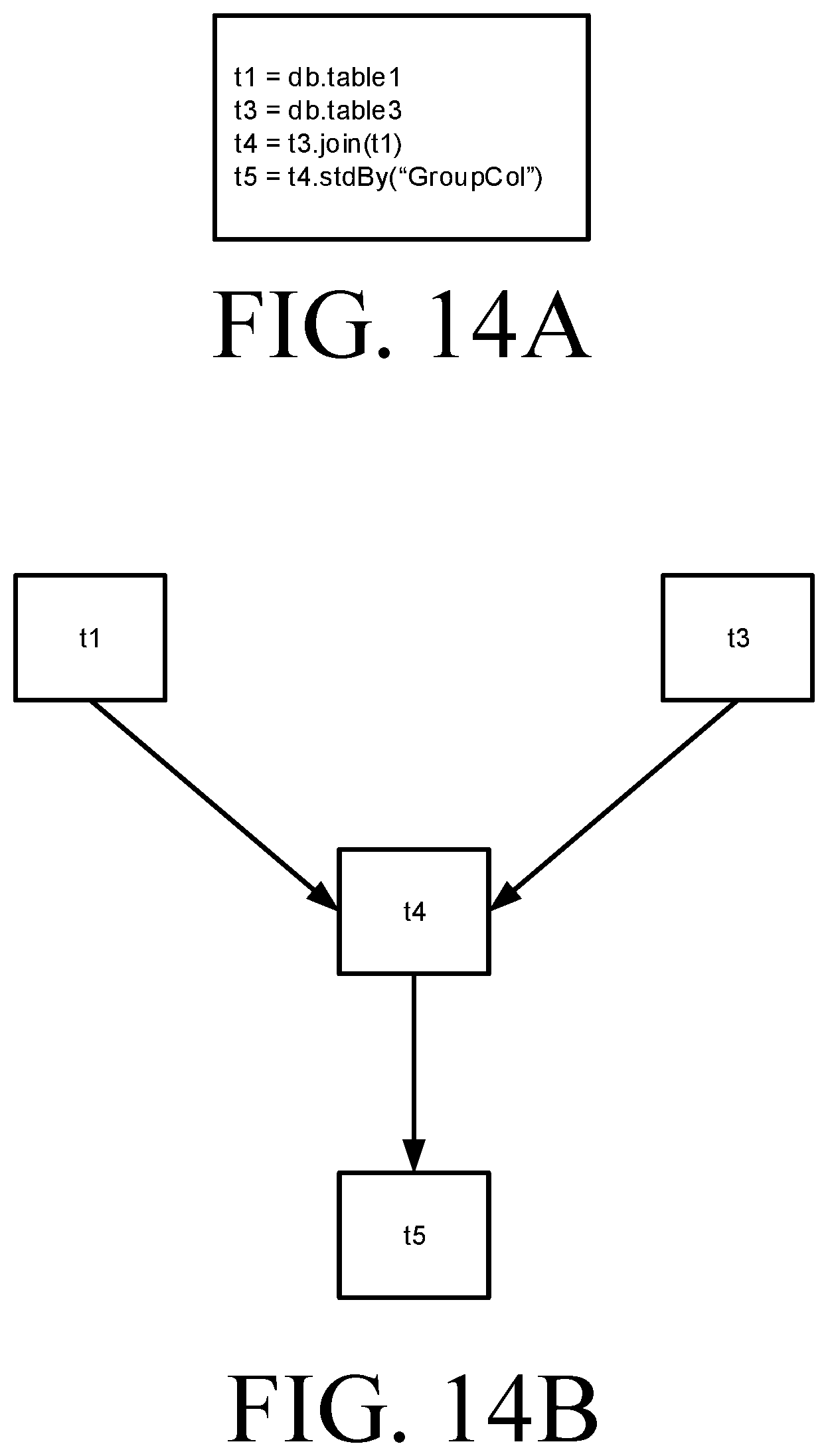
XML
uspto.report is an independent third-party trademark research tool that is not affiliated, endorsed, or sponsored by the United States Patent and Trademark Office (USPTO) or any other governmental organization. The information provided by uspto.report is based on publicly available data at the time of writing and is intended for informational purposes only.
While we strive to provide accurate and up-to-date information, we do not guarantee the accuracy, completeness, reliability, or suitability of the information displayed on this site. The use of this site is at your own risk. Any reliance you place on such information is therefore strictly at your own risk.
All official trademark data, including owner information, should be verified by visiting the official USPTO website at www.uspto.gov. This site is not intended to replace professional legal advice and should not be used as a substitute for consulting with a legal professional who is knowledgeable about trademark law.