Wearable computing device having a curved back to reduce pressure on vertebrae
Chen Feb
U.S. patent number 10,561,519 [Application Number 15/215,379] was granted by the patent office on 2020-02-18 for wearable computing device having a curved back to reduce pressure on vertebrae. This patent grant is currently assigned to TOYOTA MOTOR ENGINEERING & MANUFACTURING NORTH AMERICA, INC.. The grantee listed for this patent is Toyota Motor Engineering & Manufacturing North America, Inc.. Invention is credited to Tiffany Chen.


| United States Patent | 10,561,519 |
| Chen | February 18, 2020 |
Wearable computing device having a curved back to reduce pressure on vertebrae
Abstract
A wearable computing device includes a first side portion and a second side portion that partially extend across a shoulder and rest on a front of a user. The device also includes a neck portion connected to the first side portion and the second side portion. The neck portion includes an outer edge and an inner edge. The neck portion is curved from the first side portion to the second side portion to extend around a portion of a circumference of the neck of the user. The neck portion is also curved from the outer edge to the inner edge to follow a curvature of a spine of the user. The wearable computing device also includes an input device and a mobile processor designed to determine output data based on input data. The wearable computing device also includes an output device designed to output the output data.
| Inventors: | Chen; Tiffany (San Jose, CA) | ||||||||||
|---|---|---|---|---|---|---|---|---|---|---|---|
| Applicant: |
|
||||||||||
| Assignee: | TOYOTA MOTOR ENGINEERING &
MANUFACTURING NORTH AMERICA, INC. (Plano, TX) |
||||||||||
| Family ID: | 60990368 | ||||||||||
| Appl. No.: | 15/215,379 | ||||||||||
| Filed: | July 20, 2016 |
Prior Publication Data
| Document Identifier | Publication Date | |
|---|---|---|
| US 20180021161 A1 | Jan 25, 2018 | |
| Current U.S. Class: | 1/1 |
| Current CPC Class: | A45F 5/00 (20130101); G06F 1/163 (20130101); A61F 5/026 (20130101); A45F 2005/006 (20130101); A45F 2200/0525 (20130101) |
| Current International Class: | G06F 1/16 (20060101); H04N 5/232 (20060101); G09B 21/00 (20060101); A61F 5/02 (20060101); A45F 5/00 (20060101); G06F 3/01 (20060101); G06K 9/00 (20060101) |
| Field of Search: | ;348/62 |
References Cited [Referenced By]
U.S. Patent Documents
| 4520501 | May 1985 | DuBrucq |
| 4586827 | May 1986 | Hirsch et al. |
| 4786966 | November 1988 | Hanson |
| 5047952 | September 1991 | Kramer |
| 5097856 | March 1992 | Chi-Sheng |
| 5129716 | July 1992 | Holakovszky et al. |
| 5233520 | August 1993 | Kretsch et al. |
| 5265272 | November 1993 | Kurcbart |
| 5463428 | October 1995 | Lipton et al. |
| 5508699 | April 1996 | Silverman |
| 5539665 | July 1996 | Lamming et al. |
| 5543802 | August 1996 | Villevielle et al. |
| 5544050 | August 1996 | Abe |
| 5568127 | October 1996 | Bang |
| 5636038 | June 1997 | Lynt |
| 5659764 | August 1997 | Sakiyama |
| 5701356 | December 1997 | Stanford et al. |
| 5733127 | March 1998 | Mecum |
| 5780756 | July 1998 | Babb |
| 5807111 | September 1998 | Schrader |
| 5872744 | February 1999 | Taylor |
| 5953693 | September 1999 | Sakiyama |
| 5956630 | September 1999 | Mackey |
| 5982286 | November 1999 | Vanmoor |
| 6009577 | January 2000 | Day |
| 6055048 | April 2000 | Langevin et al. |
| 6067112 | May 2000 | Wellner et al. |
| 6199010 | March 2001 | Richton |
| 6229901 | May 2001 | Mickelson et al. |
| 6230135 | May 2001 | Ramsay |
| 6230349 | May 2001 | Silver et al. |
| 6285757 | September 2001 | Carroll et al. |
| 6307526 | October 2001 | Mann |
| 6323807 | November 2001 | Golding et al. |
| 6349001 | February 2002 | Spitzer |
| 6466232 | October 2002 | Newell et al. |
| 6477239 | November 2002 | Ohki |
| 6542623 | April 2003 | Kahn |
| 6580999 | June 2003 | Maruyama et al. |
| 6594370 | July 2003 | Anderson |
| 6603863 | August 2003 | Nagayoshi |
| 6619836 | September 2003 | Silvant et al. |
| 6701296 | March 2004 | Kramer |
| 6774788 | August 2004 | Balfe |
| 6825875 | November 2004 | Strub et al. |
| 6826477 | November 2004 | Ladetto et al. |
| 6834373 | December 2004 | Dieberger |
| 6839667 | January 2005 | Reich |
| 6857775 | February 2005 | Wilson |
| 6920229 | July 2005 | Boesen |
| D513997 | January 2006 | Wilson |
| 7027874 | April 2006 | Sawan et al. |
| D522300 | June 2006 | Roberts |
| 7069215 | June 2006 | Bangalore |
| 7106220 | September 2006 | Gourgey et al. |
| 7228275 | June 2007 | Endo |
| 7299034 | November 2007 | Kates |
| 7308314 | December 2007 | Havey et al. |
| 7336226 | February 2008 | Jung et al. |
| 7356473 | April 2008 | Kates |
| 7413554 | August 2008 | Kobayashi et al. |
| 7417592 | August 2008 | Hsiao et al. |
| 7428429 | September 2008 | Gantz et al. |
| 7463188 | December 2008 | McBurney |
| 7496445 | February 2009 | Mohsini et al. |
| 7501958 | March 2009 | Saltzstein et al. |
| 7525568 | April 2009 | Raghunath |
| 7564469 | July 2009 | Cohen |
| 7565295 | July 2009 | Hernandez-Rebollar |
| 7598976 | October 2009 | Sofer et al. |
| 7618260 | November 2009 | Daniel et al. |
| D609818 | February 2010 | Tsang |
| 7656290 | February 2010 | Fein et al. |
| 7659915 | February 2010 | Kurzweil et al. |
| 7743996 | June 2010 | Maciver |
| D625427 | October 2010 | Lee |
| 7843351 | November 2010 | Bourne |
| 7843488 | November 2010 | Stapleton |
| 7848512 | December 2010 | Eldracher |
| 7864991 | January 2011 | Espenlaub et al. |
| 7938756 | May 2011 | Rodetsky et al. |
| 7991576 | August 2011 | Roumeliotis |
| 8005263 | August 2011 | Fujimura |
| 8035519 | October 2011 | Davis |
| D649655 | November 2011 | Petersen |
| 8123660 | February 2012 | Kruse et al. |
| D656480 | March 2012 | McManigal et al. |
| 8138907 | March 2012 | Barbeau et al. |
| 8150107 | April 2012 | Kurzweil et al. |
| 8177705 | May 2012 | Abolfathi |
| 8239032 | August 2012 | Dewhurst |
| 8253760 | August 2012 | Sako et al. |
| 8300862 | October 2012 | Newton et al. |
| 8325263 | December 2012 | Kato et al. |
| D674501 | January 2013 | Petersen |
| 8359122 | January 2013 | Koselka et al. |
| 8395968 | March 2013 | Vartanian et al. |
| 8401785 | March 2013 | Cho et al. |
| 8414246 | April 2013 | Tobey |
| 8418705 | April 2013 | Ota et al. |
| 8428643 | April 2013 | Lin |
| 8483956 | July 2013 | Zhang |
| 8494507 | July 2013 | Tedesco et al. |
| 8494859 | July 2013 | Said |
| 8538687 | September 2013 | Plocher et al. |
| 8538688 | September 2013 | Prehofer |
| 8571860 | October 2013 | Strope |
| 8583282 | November 2013 | Angle et al. |
| 8588464 | November 2013 | Albertson et al. |
| 8588972 | November 2013 | Fung |
| 8591412 | November 2013 | Kovarik et al. |
| 8594935 | November 2013 | Cioffi et al. |
| 8606316 | December 2013 | Evanitsky |
| 8610879 | December 2013 | Ben-Moshe et al. |
| 8630633 | January 2014 | Tedesco et al. |
| 8676274 | March 2014 | Li |
| 8676623 | March 2014 | Gale et al. |
| 8694251 | April 2014 | Janardhanan et al. |
| 8704902 | April 2014 | Naick et al. |
| 8718672 | May 2014 | Xie et al. |
| 8743145 | June 2014 | Price |
| 8750898 | June 2014 | Haney |
| 8768071 | July 2014 | Tsuchinaga et al. |
| 8786680 | July 2014 | Shiratori et al. |
| 8797141 | August 2014 | Best et al. |
| 8797386 | August 2014 | Chou et al. |
| 8803699 | August 2014 | Foshee et al. |
| 8805929 | August 2014 | Erol et al. |
| 8812244 | August 2014 | Angelides |
| 8814019 | August 2014 | Dyster et al. |
| 8825398 | September 2014 | Alexandre et al. |
| 8836532 | September 2014 | Fish, Jr. et al. |
| 8836580 | September 2014 | Mendelson |
| 8836910 | September 2014 | Cashin et al. |
| 8902303 | December 2014 | Na'Aman et al. |
| 8909534 | December 2014 | Heath |
| D721673 | January 2015 | Park et al. |
| 8926330 | January 2015 | Taghavi |
| 8930458 | January 2015 | Lewis et al. |
| 8981682 | March 2015 | Delson et al. |
| 8994498 | March 2015 | Agrafioti |
| D727194 | April 2015 | Wilson |
| 9004330 | April 2015 | White |
| 9025016 | May 2015 | Wexler et al. |
| 9042596 | May 2015 | Connor |
| 9053094 | June 2015 | Yassa |
| 9076450 | July 2015 | Sadek |
| 9081079 | July 2015 | Chao et al. |
| 9081385 | July 2015 | Ferguson et al. |
| D736741 | August 2015 | Katz |
| 9111545 | August 2015 | Jadhav et al. |
| D738238 | September 2015 | Pede et al. |
| 9137484 | September 2015 | DiFrancesco et al. |
| 9137639 | September 2015 | Garin et al. |
| 9140554 | September 2015 | Jerauld |
| 9148191 | September 2015 | Teng et al. |
| 9158378 | October 2015 | Hirukawa |
| D742535 | November 2015 | Wu |
| D743933 | November 2015 | Park et al. |
| 9185489 | November 2015 | Gerber et al. |
| 9190058 | November 2015 | Klein |
| 9104806 | December 2015 | Stivoric et al. |
| 9230430 | January 2016 | Civelli et al. |
| 9232366 | January 2016 | Charlier et al. |
| 9267801 | February 2016 | Gupta et al. |
| 9269015 | February 2016 | Boncyk et al. |
| 9275376 | March 2016 | Barraclough et al. |
| 9304588 | April 2016 | Aldossary |
| D756958 | May 2016 | Lee et al. |
| D756959 | May 2016 | Lee et al. |
| 9335175 | May 2016 | Zhang et al. |
| 9341014 | May 2016 | Oshima et al. |
| 9355547 | May 2016 | Stevens et al. |
| D769453 | October 2016 | Ma |
| 9576460 | February 2017 | Dayal |
| 9578307 | February 2017 | Moore |
| 2001/0023387 | September 2001 | Rollo |
| 2002/0067282 | June 2002 | Moskowitz et al. |
| 2002/0071277 | June 2002 | Starner et al. |
| 2002/0075323 | June 2002 | O'Dell |
| 2002/0173346 | November 2002 | Wang |
| 2002/0178344 | November 2002 | Bourguet |
| 2003/0026461 | February 2003 | Arthur Hunter |
| 2003/0133008 | July 2003 | Stephenson |
| 2003/0133085 | July 2003 | Tretiakoff |
| 2003/0179133 | September 2003 | Pepin et al. |
| 2004/0056907 | March 2004 | Sharma |
| 2004/0232179 | November 2004 | Chauhan |
| 2004/0267442 | December 2004 | Fehr et al. |
| 2005/0020845 | September 2005 | Fink et al. |
| 2005/0221260 | October 2005 | Kikuchi |
| 2005/0259035 | November 2005 | Iwaki |
| 2005/0283752 | December 2005 | Fruchter |
| 2006/0004512 | January 2006 | Herbst et al. |
| 2006/0028550 | February 2006 | Palmer, Jr. et al. |
| 2006/0029256 | February 2006 | Miyoshi et al. |
| 2006/0129308 | June 2006 | Kates |
| 2006/0171704 | August 2006 | Bingle et al. |
| 2006/0177086 | August 2006 | Rye et al. |
| 2006/0184318 | August 2006 | Yoshimine |
| 2006/0292533 | December 2006 | Selod |
| 2007/0001904 | January 2007 | Mendelson |
| 2007/0052672 | March 2007 | Ritter et al. |
| 2007/0173688 | July 2007 | Kim |
| 2007/0182812 | August 2007 | Ritchey |
| 2007/0202865 | August 2007 | Moride |
| 2007/0230786 | October 2007 | Foss |
| 2007/0296572 | December 2007 | Fein et al. |
| 2008/0024594 | January 2008 | Ritchey |
| 2008/0068559 | March 2008 | Howell et al. |
| 2008/0120029 | May 2008 | Zelek et al. |
| 2008/0144854 | June 2008 | Abreu |
| 2008/0145822 | June 2008 | Bucchieri |
| 2008/0174676 | July 2008 | Squilla et al. |
| 2008/0198222 | August 2008 | Gowda |
| 2008/0198324 | August 2008 | Fuziak |
| 2008/0208455 | August 2008 | Hartman |
| 2008/0251110 | October 2008 | Pede |
| 2008/0260210 | October 2008 | Kobeli |
| 2009/0012788 | January 2009 | Gilbert |
| 2009/0040215 | February 2009 | Afzulpurkar |
| 2009/0058611 | March 2009 | Kawamura |
| 2009/0106016 | April 2009 | Athsani |
| 2009/0118652 | May 2009 | Carlucci |
| 2009/0122161 | May 2009 | Bolkhovitinov |
| 2009/0122648 | May 2009 | Mountain et al. |
| 2009/0157302 | June 2009 | Tashev et al. |
| 2009/0177437 | July 2009 | Roumeliotis |
| 2009/0189974 | July 2009 | Deering |
| 2009/0210596 | August 2009 | Furuya |
| 2010/0041378 | February 2010 | Aceves et al. |
| 2010/0080418 | April 2010 | Ito |
| 2010/0109918 | May 2010 | Liebermann |
| 2010/0110368 | May 2010 | Chaum |
| 2010/0179452 | July 2010 | Srinivasan |
| 2010/0182242 | July 2010 | Fields et al. |
| 2010/0182450 | July 2010 | Kumar et al. |
| 2010/0198494 | August 2010 | Chao et al. |
| 2010/0199232 | August 2010 | Mistry et al. |
| 2010/0241350 | September 2010 | Cioffi et al. |
| 2010/0245585 | September 2010 | Fisher et al. |
| 2010/0267276 | October 2010 | Wu et al. |
| 2010/0292917 | November 2010 | Emam et al. |
| 2010/0298976 | November 2010 | Sugihara et al. |
| 2010/0305845 | December 2010 | Alexandre et al. |
| 2010/0308999 | December 2010 | Chornenky |
| 2011/0066383 | March 2011 | Jangle et al. |
| 2011/0071830 | March 2011 | Kim |
| 2011/0092249 | April 2011 | Evanitsky |
| 2011/0124383 | May 2011 | Garra et al. |
| 2011/0125735 | May 2011 | Petrou |
| 2011/0181422 | July 2011 | Tran |
| 2011/0187640 | August 2011 | Jacobsen et al. |
| 2011/0211760 | September 2011 | Boncyk et al. |
| 2011/0216006 | September 2011 | Litschel |
| 2011/0221670 | September 2011 | King, III et al. |
| 2011/0234584 | September 2011 | Endo |
| 2011/0246064 | October 2011 | Nicholson |
| 2011/0260681 | October 2011 | Guccione et al. |
| 2011/0307172 | December 2011 | Jadhav et al. |
| 2012/0016578 | January 2012 | Coppens |
| 2012/0053826 | March 2012 | Slamka |
| 2012/0062357 | March 2012 | Slamka |
| 2012/0069511 | March 2012 | Azera |
| 2012/0075168 | March 2012 | Osterhout et al. |
| 2012/0082962 | April 2012 | Schmidt |
| 2012/0085377 | April 2012 | Trout |
| 2012/0092161 | April 2012 | West |
| 2012/0092460 | April 2012 | Mahoney |
| 2012/0123784 | May 2012 | Baker et al. |
| 2012/0136666 | May 2012 | Corpier et al. |
| 2012/0143495 | June 2012 | Dantu |
| 2012/0162423 | June 2012 | Xiao et al. |
| 2012/0194552 | August 2012 | Osterhout et al. |
| 2012/0206335 | August 2012 | Osterhout et al. |
| 2012/0206607 | August 2012 | Morioka |
| 2012/0207356 | August 2012 | Murphy |
| 2012/0214418 | August 2012 | Lee et al. |
| 2012/0220234 | August 2012 | Abreu |
| 2012/0232430 | September 2012 | Boissy et al. |
| 2012/0249797 | October 2012 | Haddick et al. |
| 2012/0252483 | October 2012 | Farmer et al. |
| 2012/0316884 | December 2012 | Rozaieski et al. |
| 2012/0323485 | December 2012 | Mutoh |
| 2012/0327194 | December 2012 | Shiratori |
| 2013/0002452 | January 2013 | Lauren |
| 2013/0044005 | February 2013 | Foshee et al. |
| 2013/0046541 | February 2013 | Klein et al. |
| 2013/0066636 | March 2013 | Singhal |
| 2013/0079061 | March 2013 | Jadhav |
| 2013/0090133 | April 2013 | D'Jesus Bencci |
| 2013/0115578 | May 2013 | Shiina |
| 2013/0115579 | May 2013 | Taghavi |
| 2013/0116559 | May 2013 | Levin et al. |
| 2013/0127980 | May 2013 | Haddick |
| 2013/0128051 | May 2013 | Velipasalar et al. |
| 2013/0131985 | May 2013 | Weiland et al. |
| 2013/0141576 | June 2013 | Lord et al. |
| 2013/0144629 | June 2013 | Johnston |
| 2013/0145531 | June 2013 | Fratesi |
| 2013/0155474 | June 2013 | Roach et al. |
| 2013/0157230 | June 2013 | Morgan |
| 2013/0184982 | July 2013 | DeLuca et al. |
| 2013/0201344 | August 2013 | Sweet, III |
| 2013/0202274 | August 2013 | Chan |
| 2013/0204605 | August 2013 | Illgner-Fehns |
| 2013/0211718 | August 2013 | Yoo et al. |
| 2013/0218456 | August 2013 | Zelek et al. |
| 2013/0228615 | September 2013 | Gates et al. |
| 2013/0229669 | September 2013 | Smits |
| 2013/0243250 | September 2013 | France |
| 2013/0245396 | September 2013 | Berman et al. |
| 2013/0250078 | September 2013 | Levy |
| 2013/0250233 | September 2013 | Blum et al. |
| 2013/0253818 | September 2013 | Sanders et al. |
| 2013/0265450 | October 2013 | Barnes, Jr. |
| 2013/0271584 | October 2013 | Wexler et al. |
| 2013/0290909 | October 2013 | Gray |
| 2013/0307842 | November 2013 | Grinberg et al. |
| 2013/0311179 | November 2013 | Wagner |
| 2013/0328683 | December 2013 | Sitbon et al. |
| 2013/0332452 | December 2013 | Jarvis |
| 2014/0009561 | January 2014 | Sutherland et al. |
| 2014/0031081 | January 2014 | Vossoughi et al. |
| 2014/0031977 | January 2014 | Goldenberg et al. |
| 2014/0032596 | January 2014 | Fish et al. |
| 2014/0037149 | February 2014 | Zetune |
| 2014/0055353 | February 2014 | Takahama |
| 2014/0071234 | March 2014 | Millett |
| 2014/0081631 | March 2014 | Zhu et al. |
| 2014/0085446 | March 2014 | Hicks |
| 2014/0098018 | April 2014 | Kim et al. |
| 2014/0100773 | April 2014 | Cunningham et al. |
| 2014/0125700 | May 2014 | Ramachandran et al. |
| 2014/0132388 | May 2014 | Alalawi |
| 2014/0133290 | May 2014 | Yokoo |
| 2014/0160250 | June 2014 | Pomerantz |
| 2014/0184384 | July 2014 | Zhu et al. |
| 2014/0184775 | July 2014 | Drake |
| 2014/0204245 | July 2014 | Wexler |
| 2014/0222023 | August 2014 | Kim et al. |
| 2014/0233859 | August 2014 | Cho |
| 2014/0236932 | August 2014 | Ikonomov |
| 2014/0249847 | September 2014 | Soon-Shiong |
| 2014/0251396 | September 2014 | Subhashrao et al. |
| 2014/0253702 | September 2014 | Wexler et al. |
| 2014/0278070 | September 2014 | McGavran et al. |
| 2014/0281943 | September 2014 | Prilepov |
| 2014/0287382 | September 2014 | Villar Cloquell |
| 2014/0309806 | October 2014 | Ricci |
| 2014/0313040 | October 2014 | Wright, Sr. |
| 2014/0335893 | November 2014 | Ronen |
| 2014/0343846 | November 2014 | Goldman et al. |
| 2014/0345956 | November 2014 | Kojina |
| 2014/0347265 | November 2014 | Aimone |
| 2014/0368412 | December 2014 | Jacobsen et al. |
| 2014/0369541 | December 2014 | Miskin et al. |
| 2014/0379251 | December 2014 | Tolstedt |
| 2014/0379336 | December 2014 | Bhatnager |
| 2015/0002808 | January 2015 | Rizzo, III et al. |
| 2015/0016035 | January 2015 | Tussy |
| 2015/0058237 | February 2015 | Bailey |
| 2015/0063661 | March 2015 | Lee |
| 2015/0081884 | March 2015 | Maguire |
| 2015/0099946 | April 2015 | Sahin |
| 2015/0109107 | April 2015 | Gomez et al. |
| 2015/0120186 | April 2015 | Heikes |
| 2015/0125831 | May 2015 | Chandrashekhar Nair et al. |
| 2015/0135310 | May 2015 | Lee |
| 2015/0141085 | May 2015 | Nuovo et al. |
| 2015/0142891 | May 2015 | Haque et al. |
| 2015/0154643 | June 2015 | Artman et al. |
| 2015/0196101 | July 2015 | Dayal |
| 2015/0198454 | July 2015 | Moore et al. |
| 2015/0198455 | July 2015 | Chen et al. |
| 2015/0199566 | July 2015 | Moore et al. |
| 2015/0201181 | July 2015 | Moore et al. |
| 2015/0211858 | July 2015 | Jerauld |
| 2015/0219757 | August 2015 | Boelter et al. |
| 2015/0223355 | August 2015 | Fleck |
| 2015/0256977 | September 2015 | Huang |
| 2015/0257555 | September 2015 | Wong |
| 2015/0260474 | September 2015 | Rublowsky et al. |
| 2015/0262509 | September 2015 | Labbe |
| 2015/0279172 | October 2015 | Hyde |
| 2015/0324646 | November 2015 | Kimia |
| 2015/0330787 | November 2015 | Cioffi et al. |
| 2015/0336276 | November 2015 | Song et al. |
| 2015/0338917 | November 2015 | Steiner et al. |
| 2015/0341591 | November 2015 | Kelder et al. |
| 2015/0346496 | December 2015 | Haddick et al. |
| 2015/0356345 | December 2015 | Velozo |
| 2015/0356837 | December 2015 | Pajestka et al. |
| 2015/0364943 | December 2015 | Vick et al. |
| 2015/0367176 | December 2015 | Bejestan |
| 2015/0375395 | December 2015 | Kwon et al. |
| 2016/0007158 | January 2016 | Venkatraman |
| 2016/0028917 | January 2016 | Wexler |
| 2016/0042228 | February 2016 | Opalka |
| 2016/0078289 | March 2016 | Michel |
| 2016/0085278 | March 2016 | Osterhout |
| 2016/0098138 | April 2016 | Park |
| 2016/0156850 | June 2016 | Werblin et al. |
| 2016/0198319 | July 2016 | Huang |
| 2016/0350514 | December 2016 | Rajendran |
| 201260746 | Jun 2009 | CN | |||
| 101527093 | Sep 2009 | CN | |||
| 201440733 | Apr 2010 | CN | |||
| 101803988 | Aug 2010 | CN | |||
| 101647745 | Jan 2011 | CN | |||
| 102316193 | Jan 2012 | CN | |||
| 102631280 | Aug 2012 | CN | |||
| 202547659 | Nov 2012 | CN | |||
| 202722736 | Feb 2013 | CN | |||
| 102323819 | Jun 2013 | CN | |||
| 103445920 | Dec 2013 | CN | |||
| 102011080056 | Jan 2013 | DE | |||
| 102012000587 | Jul 2013 | DE | |||
| 102012202614 | Aug 2013 | DE | |||
| 1174049 | Sep 2004 | EP | |||
| 1721237 | Nov 2006 | EP | |||
| 2368455 | Sep 2011 | EP | |||
| 2371339 | Oct 2011 | EP | |||
| 2127033 | Aug 2012 | EP | |||
| 2581856 | Apr 2013 | EP | |||
| 2751775 | Jul 2016 | EP | |||
| 2885251 | Nov 2006 | FR | |||
| 2401752 | Nov 2004 | GB | |||
| 1069539 | Mar 1998 | JP | |||
| 2001304908 | Oct 2001 | JP | |||
| 2010012529 | Jan 2010 | JP | |||
| 2010182193 | Aug 2010 | JP | |||
| 4727352 | Jul 2011 | JP | |||
| 2013169611 | Sep 2013 | JP | |||
| 100405636 | Nov 2003 | KR | |||
| 20080080688 | Sep 2008 | KR | |||
| 20120020212 | Mar 2012 | KR | |||
| 1250929 | Apr 2013 | KR | |||
| WO 1995004440 | Feb 1995 | WO | |||
| WO 9949656 | Sep 1999 | WO | |||
| WO 0010073 | Feb 2000 | WO | |||
| WO 0038393 | Jun 2000 | WO | |||
| WO 179956 | Oct 2001 | WO | |||
| WO 2004/076974 | Sep 2004 | WO | |||
| WO 2006/028354 | Mar 2006 | WO | |||
| WO 2006/045819 | May 2006 | WO | |||
| WO 2007/031782 | Mar 2007 | WO | |||
| WO 2008015375 | Feb 2008 | WO | |||
| WO 2008/035993 | Mar 2008 | WO | |||
| WO 2008/008791 | Apr 2008 | WO | |||
| WO 2008/096134 | Aug 2008 | WO | |||
| WO 2008127316 | Oct 2008 | WO | |||
| WO 2010/062481 | Jun 2010 | WO | |||
| WO 2010/109313 | Sep 2010 | WO | |||
| WO 2012/040703 | Mar 2012 | WO | |||
| WO 2012163675 | Dec 2012 | WO | |||
| WO 2013/045557 | Apr 2013 | WO | |||
| WO 2013/054257 | Apr 2013 | WO | |||
| WO 2013/067539 | May 2013 | WO | |||
| WO 2013/147704 | Oct 2013 | WO | |||
| WO 2014104531 | Jul 2014 | WO | |||
| WO 2014/138123 | Sep 2014 | WO | |||
| WO 2014/172378 | Oct 2014 | WO | |||
| WO 2015065418 | May 2015 | WO | |||
| WO 2015092533 | Jun 2015 | WO | |||
| WO 2015108882 | Jul 2015 | WO | |||
| WO 2015127062 | Aug 2015 | WO | |||
Other References
|
Zhang, Shanjun; Yoshino, Kazuyoshi; A Braille Recognition System by the Mobile Phone with Embedded Camera; 2007; IEEE. cited by applicant . Diallo, Amadou; Sep. 18, 2014; Apple iOS8: Top New Features, Forbes Magazine. cited by applicant . N. Kalar, T. Lawers, D. Dewey, T. Stepleton, M.B. Dias; Iterative Design of a Braille Writing Tutor to Combat Illiteracy; Aug. 30, 2007; IEEE. cited by applicant . AIZuhair et al.; "NFC Based Applications for Visually Impaired People--A Review"; IEEE International Conference on Multimedia and Expo Workshops (ICMEW), Jul. 14, 2014; 7 pages. cited by applicant . "Light Detector" EveryWare Technologies; 2 pages; Jun. 18, 2016. cited by applicant . Aggarwal et al.; "All-in-One Companion for Visually Impaired;" International Journal of Computer Applications; vol. 79, No. 14; pp. 37-40; Oct. 2013. cited by applicant . AppleVis; An Introduction to Braille Screen Input on iOS 8; http://www.applevis.com/guides/braille-ios/introduction-braille-screen-in- put-ios-8, Nov. 16, 2014; 7 pages. cited by applicant . Arati et al. "Object Recognition in Mobile Phone Application for Visually Impaired Users;" IOSR Journal of Computer Engineering (IOSR-JCE); vol. 17, Impaired No. 1; pp. 30-33; Jan. 2015. cited by applicant . Bharathi et al.; "Effective Navigation for Visually Impaired by Wearable Obstacle Avoidance System;" 2012 International Conference on Computing, Electronics and Electrical Technologies (ICCEET); pp. 956-958; 2012. cited by applicant . Bhatlawande et al.; "Way-finding Electronic Bracelet for Visually Impaired People"; IEEE Point-of-Care Healthcare Technologies (PHT), Jan. 16-18, 2013; 4 pages. cited by applicant . Bigham et al.; "VizWiz: Nearly Real-Time Answers to Visual Questions" Proceedings of the 23nd annual ACM symposium on User interface software and technology; 2010; 2 pages. cited by applicant . Blaze Engineering; "Visually Impaired Resource Guide: Assistive Technology for Students who use Braille"; Braille 'n Speak Manual; http://www.blaize.com; Nov. 17, 2014; 5 pages. cited by applicant . Blenkhorn et al.; "An Ultrasonic Mobility Device with Minimal Audio Feedback"; Center on Disabilities Technology and Persons with Disabilities Conference; Nov. 22, 1997; 5 pages. cited by applicant . Borenstein et al.; "The GuideCane--A Computerized Travel Aid for the Active Guidance of Blind Pedestrians"; IEEE International Conference on Robotics and Automation; Apr. 21-27, 1997; 6 pages. cited by applicant . Bujacz et al.; "Remote Guidance for the Blind--A Proposed Teleassistance System and Navigation Trials"; Conference on Human System Interactions; May 25-27, 2008; 6 pages. cited by applicant . Burbey et al.; "Human Information Processing with the Personal Memex"; ISE 5604 Fall 2005; Dec. 6, 2005; 88 pages. cited by applicant . Campos et al.; "Design and Evaluation of a Spoken-Feedback Keyboard"; Department of Information Systems and Computer Science, INESC-ID/IST/Universidade Tecnica de Lisboa, Jul. 2004; 6 pages. cited by applicant . Caperna et al.; "A Navigation and Object Location Device for the Blind"; Tech. rep. University of Maryland College Park; May 2009; 129 pages. cited by applicant . Cardonha et al.; "A Crowdsourcing Platform for the Construction of Accessibility Maps"; W4A'13 Proceedings of the 10.sup.th International Cross-Disciplinary Conference on Web Accessibility; Article No. 26; 2013; 5 pages. cited by applicant . Chaudary et al.; "Alternative Navigation Assistance Aids for Visually Impaired Blind Persons"; Proceedings of ICEAPVI; Feb. 12-14, 2015; 5 pages. cited by applicant . Coughlan et al.; "Crosswatch: A System for Providing Guidance to Visually Impaired Travelers at Traffic Intersections"; Journal of Assistive Technologies 7.2; 2013; 17 pages. cited by applicant . D'Andrea, Frances Mary; "More than a Perkins Brailler: A Review of the Mountbatten Brailler, Part 1"; AFB AccessWorld Magazine; vol. 6, No. 1, Jan. 2005; 9 pages. cited by applicant . Dias et al.; "Enhancing an Automated Braille Writing Tutor"; IEEE/RSJ International Conference on Intelligent Robots and Systems; Oct. 11-15, 2009; 7 pages. cited by applicant . Dowling et al.; "Intelligent Image Processing Constraints for Blind Mobility Facilitated Through Artificial Vision"; 8.sup.th Australian and NewZealand Intelligent Information Systems Conference (ANZIIS); Dec. 10-12, 2003; 7 pages. cited by applicant . Ebay; MATIN (Made in Korea) Neoprene Canon DSLR Camera Curved Neck Strap #6782; http://www.ebay.com/itm/MATIN-Made-in-Korea-Neoprene-Canon-DSLR-Ca- mera-Curved-Neck-Strap-6782-/281608526018?hash=item41912d18c2:g:.about.pMA- AOSwe-FU6zDa ; 4 pages. cited by applicant . Eccles, Lisa; "Smart Walker Detects Obstacles"; Electronic Design; http://electronicdesign.com/electromechanical/smart-walker-detects-obstae- les; Aug. 20, 2001; 2 pages. cited by applicant . Frizera et al.; "The Smart Walkers as Geriatric Assistive Device. The SIMBIOSIS Purpose"; Gerontechnology, vol. 7, No. 2; Jan. 30, 2008; 6 pages. cited by applicant . Garaj et al.; "A System for Remote Sighted Guidance of Visually Impaired Pedestrians"; The British Journal of Visual. Impairment; vol. 21, No. 2, 2003; 9 pages. cited by applicant . Ghiani, et al.; "Vibrotactile Feedback to Aid Blind Users of Mobile Guides"; Journal of Visual Languages and Computing 20; 2009; 13 pages. cited by applicant . Glover et al.; "A Robotically-Augmented Walker for Older Adults"; Carnegie Mellon University, School of Computer Science; Aug. 1, 2003; 13 pages. cited by applicant . Graf, Christian; "Verbally Annotated Tactile Maps--Challenges and Approaches"; Spatial Cognition VII, vol. 6222; Aug. 15-19, 2010; 16 pages. cited by applicant . Graft, Birgit; "An Adaptive Guidance System for Robotic Walking Aids"; Journal of Computing and Information Technology--CIT 17; 2009; 12 pages. cited by applicant . Greenberg et al.; "Finding Your Way: A Curriculum for Teaching and Using the Braillenote with Sendero GPS 2011"; California School for the Blind; 2011; 190 pages. cited by applicant . Guerrero et al.; "An Indoor Navigation System for the Visually Impaired"; Sensors vol. 12, Issue 6; Jun. 13, 2012; 23 pages. cited by applicant . Guy et al; "CrossingGuard: Exploring Information Content in Navigation Aids for Visually Impaired Pedestrians" Proceedings of the SIGCHI Conference on Human Factors in Computing Systems; May 5-10, 2012; 10 pages. cited by applicant . Hamid, Nazatul Naquiah Abd; "Facilitating Route Learning Using Interactive Audio-Tactile Maps for Blind and Visually Impaired People"; CHI 2013 Extended Abstracts; Apr. 27, 2013; 6 pages. cited by applicant . Helal et al.; "Drishti: An Integrated Navigation System for Visually Impaired and Disabled"; Fifth International Symposium on Wearable Computers; Oct. 8-9, 2001; 8 pages. cited by applicant . Hesch et al.; "Design and Analysis of a Portable Indoor Localization Aid for the Visually Impaired"; International Journal of Robotics Research; vol. 29; Issue 11; Sep. 2010; 15 pgs. cited by applicant . Heyes, Tony; "The Sonic Pathfinder an Electronic Travel Aid for the Vision Impaired"; http://members.optuszoo.com.au/aheyew40/pa/pf_blerf.html; Dec. 11, 2014; 7 pages. cited by applicant . Joseph et al.; "Visual Semantic Parameterization--To Enhance Blind User Perception for Indoor Navigation"; Multimedia and Expo Workshops (ICMEW), 2013 IEEE International Conference; Jul. 15, 2013; 7 pages. cited by applicant . Kalra et al.; "A Braille Writing Tutor to Combat Illiteracy in Developing Communities"; Carnegie Mellon University Research Showcase, Robotics Institute; 2007; 10 pages. cited by applicant . Kammoun et al.; "Towards a Geographic Information System Facilitating Navigation of Visually Impaired Users"; Springer Berlin Heidelberg; 2012; 8 pages. cited by applicant . Katz et al; "NAVIG: Augmented Reality Guidance System for the Visually Impaired"; Virtual Reality (2012) vol. 16; 2012; 17 pages. cited by applicant . Kayama et al.; "Outdoor Environment Recognition and Semi-Autonomous Mobile Vehicle for Supporting Mobility of the Elderly and Disabled People"; National Institute of Information and Communications Technology, vol. 54, No. 3; Aug. 2007; 11 pages. cited by applicant . Kirinic et al.; "Computers in Education of Children with Intellectual and Related Developmental Disorders"; International Journal of Emerging Technologies in Learning, vol. 5, 2010, 5 pages. cited by applicant . Krishna et al.; "A Systematic Requirements Analysis and Development of an Assistive Device to Enhance the Social Interaction of People Who are Blind or Visually Impaired"; Workshop on Computer Vision Applications for the Visually Impaired; Marseille, France; 2008; 12 pages. cited by applicant . Kumar et al.; "An Electronic Travel Aid for Navigation of Visually Impaired Persons"; Communications Systems and Networks (COMSNETS), 2011 Third International Conference; Jan. 2011; 5 pages. cited by applicant . Lee et al.; "Adaptive Power Control of Obstacle Avoidance System Using via Motion Context for Visually Impaired Person." International Conference on Cloud Computing and Social Networking (ICCCSN), Apr. 26-27, 2012 4 pages. cited by applicant . Lee et al.; "A Walking Guidance System for the Visually Impaired"; International Journal of Pattern Recognition and Artificial Intelligence; vol. 22; No. 6; 2008; 16 pages. cited by applicant . Mann et al.; "Blind Navigation with a Wearable Range Camera and Vibrotactile Helmet"; 19.sup.th ACM International Conference on Multimedia; Nov. 28, 2011; 4 pages. cited by applicant . Mau et al.; "BlindAid: An Electronic Travel Aid for the Bling;" The Robotics Institute Carnegie Mellon University; 27 pages; May 2008. cited by applicant . Meijer, Dr. Peter B.L.; "Mobile OCR, Face and Object Recognition for the Blind"; The vOICe, www.seeingwithsound.com/ocr.htm; Apr. 18, 2014; 7 pages. cited by applicant . Merino-Garcia, et al.; "A Head-Mounted Device for Recognizing Text in Natural Sciences"; CBDAR'11 Proceedings of the 4.sup.th International Conference on Camera-Based Document Analysis and Recognition; Sep. 22, 2011; 7 pages. cited by applicant . Merri et al.; "The Instruments for a Blind Teacher of English: The challenge of the board"; European Journal of Psychology of Education, vol. 20, No. 4 (Dec. 2005), 15 pages. cited by applicant . NEWEGG; Motorola Behind the Neck Stereo Bluetooth Headphone Black/Red Bulk (S9)--OEM; http://www.newegg.com/Product/Product.aspx?Item=N82E16875982212&Tpk=n82e1- 6875982212 3 pages. cited by applicant . NEWEGG; Motorola S10-HD Bluetooth Stereo Headphone w/ Comfortable Sweat Proof Design; http://www.newegg.com/Product/Product.aspx?Item=9SIA0NW2G39901&Tpk=9sia0n- w2g39901; 4 pages. cited by applicant . Nordin et al.; "Indoor Navigation and Localization for Visually Impaired People Using Weighted Topological Map"; Journal of Computer Science vol. 5, Issue 11; 2009; 7 pages. cited by applicant . OMRON; Optical Character Recognition Sensor User's Manual; 2012; 450 pages. cited by applicant . OrCam; www.orcam.com; Jul. 22, 2014; 3 pages. cited by applicant . Pagliarini et al.; "Robotic Art for Wearable"; Proceedings of EUROSIAM: European Conference for the Applied Mathematics and Informatics 2010; 10 pages. cited by applicant . Paladugu et al.; "GoingEasy.RTM. with Crowdsourcing in the Web 2.0 World for Visually Impaired Users: Design and User Study"; Arizona State University; 8 pages. cited by applicant . Park, Sungwoo; "Voice Stick"; www.yankodesign.com/2008/08/21/voice-stick; Aug. 21, 2008; 4 pages. cited by applicant . Parkes, Don; "Audio Tactile Systems for Designing and Learning Complex Environments as a Vision Impaired Person: Static and Dynamic Spatial Information Access"; EdTech-94 Proceedings; 1994; 8 pages. cited by applicant . Pawar et al.; "Multitasking Stick for Indicating Safe Path to Visually Disable People"; IOSR Journal of Electronics and Communication Engineering (IOSR-JECE), vol. 10, Issue 3, Ver. II; May-Jun. 2015; 5 pages. cited by applicant . Pawar et al.; "Review Paper on Multitasking Stick for Guiding Safe Path for Visually Disable People;" IJPRET; vol. 3, No. 9; pp. 929-936; 2015. cited by applicant . Ram et al.; "The People Sensor: A Mobility Aid for the Visually Impaired;" 2012 16.sup.th International Symposium on Wearable Computers; pp. 166-167; 2012. cited by applicant . Ramya, et al.; "Voice Assisted Embedded Navigation System for the Visually Impaired"; International Journal of Computer Applications; vol. 64, No. 13, Feb. 2013; 7 pages. cited by applicant . Ran et al.; "Drishti: An Integrated Indoor/Outdoor Blind Navigation System and Service"; Proceeding PERCOM '04 Proceedings of the Second IEEE International Conference on Pervasive Computing and Communications (PerCom'04); 2004; 9 pages. cited by applicant . Rentschler et al.; "Intelligent Walkers for the Elderly: Performance and Safety Testing of VA-PAMAID Robotic Walker"; Department of Veterans Affairs Journal of Rehabilitation Research and Development; vol. 40, No. 5; Sep./Oct. 2013; 9pages. cited by applicant . Rodriguez et al.; "Assisting the Visually Impaired: Obstacle Detection and Warning System by Acoustic Feedback"; Sensors 2012; vol. 12; 21 pages. cited by applicant . Rodriguez et al; "CrowdSight: Rapidly Prototyping Intelligent Visual Processing Apps"; AAAI Human Computation Workshop (HCOMP); 2011; 6 pages. cited by applicant . Rodriquez-Losada et al.; "Guido, The Robotic Smart Walker for the Frail Visually Impaired"; IEEE International Conference on Robotics and Automation (ICRA); Apr. 18-22, 2005; 15 pages. cited by applicant . Science Daily; "Intelligent Walker Designed to Assist the Elderly and People Undergoing Medical Rehabilitation"; http://www.sciencedaily.com/releases/2008/11/081107072015.htm; Jul. 22, 2014; 4 pages. cited by applicant . Shoval et al.; "Navbelt and the Guidecane--Robotics-Based Obstacle-Avoidance Systems for the Blind and Visually Impaired"; IEEE Robotics & Automation Magazine, vol. 10, Issue 1; Mar. 2003; 12 pages. cited by applicant . Shoval et al.; "The Navbelt--A Computerized Travel Aid for the Blind"; RESNA Conference, Jun. 12-17, 1993; 6 pages. cited by applicant . Singhal; "The Development of an Intelligent Aid for Blind and Old People;" Emerging Trends and Applications in Computer Science (ICETACS), 2013 1.sup.st International Conference; pp. 182-185; Sep. 13, 2013. cited by applicant . Sudol et al.; "LookTel--A Comprehensive Platform for Computer-Aided Visual Assistance"; Computer Vision and Pattern Recognition Workshops (CVPRW), 2010 IEEE Computer Society Conference; Jun. 13-18, 2010; 8 pages. cited by applicant . The Nex Band; http://www.mightycast.com/#faq; May 19, 2015; 4 pages. cited by applicant . Treuillet; "Outdoor/Indoor Vision-Based Localization for Blind Pedestrian Navigation Assistance"; WSPC/Instruction File; May 23, 2010; 16 pages. cited by applicant . Trinh et al.; "Phoneme-based Predictive Text Entry Interface"; Proceedings of the 16th International ACM SIGACCESS Conference on Computers & Accessibility; Oct. 2014; 2 pgs. cited by applicant . Wang, et al.; "Camera-Based Signage Detection and Recognition for Blind Persons"; 13.sup.th International Conference (ICCHP) Part 2 Proceedings; Jul. 11-13, 2012; 9 pages. cited by applicant . Ward et al.; "Visual Experiences in the Blind Induced by an Auditory Sensory Substitution Device"; Journal of Consciousness and Cognition; Oct. 2009; 30 pages. cited by applicant . Wilson, Jeff, et al. "Swan: System for Wearable Audio Navigation"; 11th IEEE International Symposium on Wearable Computers; Oct. 11-13, 2007; 8 pages. cited by applicant . Yabu et al.; "Development of a Wearable Haptic Tactile Interface as an Aid for the Hearing and/or Visually Impaired;" NTUT Education of Disabilities; vol. 13; pp. 5-12; 2015. cited by applicant . Yang, et al.; "Towards Automatic Sign Translation"; The Interactive Systems Lab, Carnegie Mellon University; 2001; 5 pages. cited by applicant . Yi, Chucai; "Assistive Text Reading from Complex Background for Blind Persons"; CBDAR'11 Proceedings of the 4.sup.th International Conference on Camera-Based Document Analysis and Recognition; Sep. 22, 2011; 7 pages. cited by applicant . Zeng et al.; "Audio-Haptic Browser for a Geographical Information System"; ICCHP 2010, Part II, LNCS 6180; Jul. 14-16, 2010; 8 pages. cited by applicant . Zhang et al.; "A Multiple Sensor-Based Shoe-Mounted User Interface Designed for Navigation Systems for the Visually Impaired"; 5.sup.th Annual ICST Wireless Internet Conference (WICON); Mar. 1-3, 2010; 9 pages. cited by applicant . Shidujaman et al.; "Design and navigation Prospective for Wireless Power Transmission Robot;" IEEE; Jun. 2015. cited by applicant . Wu et al. "Fusing Multi-Modal Features for Gesture Recognition", Proceedings of the 15.sup.th ACM on International Conference on Multimodal Interaction, Dec. 9, 2013, ACM, pp. 453-459. cited by applicant . Pitsikalis et al. "Multimodal Gesture Recognition via Multiple Hypotheses Rescoring", Journal of Machine Learning Research, Feb. 2015, pp. 255-284. cited by applicant . Shen et al. "Walkie-Markie: Indoor Pathway Mapping Made Easy" 10.sup.th USENIX Symposium on Networked Systems Design and Implementation (NSDI'13); pp. 85-98, 2013. cited by applicant . Tu et al. "Crowdsourced Routing II D2.6" 34 pages; 2012. cited by applicant . De Choudhury et al. "Automatic Construction of Travel Itineraries Using Social Breadcrumbs" pp. 35-44; Jun. 2010. cited by applicant. |
Primary Examiner: Hodges; Susan E.
Attorney, Agent or Firm: Snell & Wilmer LLP
Claims
What is claimed is:
1. A wearable computing device, comprising: a first side portion and a second side portion each configured to at least partially extend across a shoulder of a user and to rest on a front of the user; a neck portion having an inner housing and an outer housing configured to be coupled together and to define a cavity, the neck portion having a first end connected to the first side portion, a second end connected to the second side portion, a center portion that is in between the first end and the second end and that has a width that extends from a neck of the user to a thoracic portion of a spine of the user, an outer edge, an inner edge that is positioned nearer the neck of the user than the outer edge when the wearable computing device is worn, a contact surface that extends the width of the center portion and is configured to contact and rest flush with the thoracic portion of the spine of the user when the wearable computing device is worn, and an exposed surface defined by the outer housing and oriented opposite the contact surface, a curvature of the neck portion extending from the inner edge to the outer edge along the width of the center portion; an input device configured to detect input data; a mobile processor positioned in the cavity, coupled to the input device, and configured to determine output data based on the input data; an output device coupled to the mobile processor and configured to output the output data; a thermal pad positioned in the cavity, in contact with the mobile processor such that the mobile processor is located between the thermal pad and the contact surface, and configured to transfer heat from the mobile processor; and a heat spreader located in the cavity and configured to distribute the heat from the mobile processor via the thermal pad.
2. The wearable computing device of claim 1 further comprising a padding coupled to the neck portion and configured to contact the user when the wearable computing device is worn.
3. The wearable computing device of claim 2 wherein the padding includes a first padding that extends from a first location away from a halfway point along the width of the neck portion to the first end of the neck portion and a second padding that extends from a second location away from the halfway point to the second end of the neck portion such that the spine of the user is positioned between the first padding and the second padding when the wearable computing device is worn.
4. The wearable computing device of claim 1 wherein the inner edge of the neck portion is positioned at a height that is substantially equal to a height of shoulders of the user when the wearable computing device is worn.
5. The wearable computing device of claim 1 wherein the mobile processor is further configured to operate in a first mode in which it generates navigation instructions to a desired location and in a second mode in which it recognizes objects in an environment.
6. The wearable computing device of claim 1 wherein the output device includes a first output unit and a second output unit that each include a speaker and a vibration unit for providing at least one of stereo audio output or stereo haptic output.
7. The wearable computing device of claim 1 wherein the curvature from the inner edge of the neck portion to the outer edge of the neck portion resembles a curvature of the spine of the user from a cervical portion of the spine to the thoracic portion of the spine.
8. The wearable computing device of claim 1 wherein each of the first side portion and the second side portion includes a rigid portion configured to rest on the front of the user when the wearable computing device is worn, and a flexible portion positioned between the rigid portion and the neck portion and configured to at least partially extend across the shoulder of the user.
9. A wearable computing device, comprising: a first side portion and a second side portion each configured to at least partially extend across a shoulder of a user and to rest on a front of the user; a neck portion having an inner housing and an outer housing configured to be coupled together and to define a cavity, the neck portion having a first end connected to the first side portion, a second end connected to the second side portion, a center portion that in between the first end and the second end and that has a width that extends from a neck of the user to a thoracic portion of a spine of the user, an outer edge, an inner edge that is positioned nearer the neck of the user than the outer edge when the wearable computing device is worn, a contact surface that extends the width of the center portion and is configured to contact and rest flush with the thoracic portion of the spine of the user when the wearable computing device is worn, and an exposed surface defined by the outer housing and oriented opposite the contact surface, a curvature of the neck portion extending from the inner edge to the outer edge along the width of the center portion; a padding that is coupled to the neck portion and spans the entire contact surface to distribute weight on the user; a camera configured to detect image data; a mobile processor positioned in the cavity, coupled to the camera, and configured to recognize objects based on the image data and determine navigation instructions based on the image data; a speaker coupled to the mobile processor and configured to output data corresponding to the recognized objects or the determined navigation instructions; a thermal pad positioned in the cavity, in contact with the mobile processor such that the mobile processor is located between the thermal pad and the contact surface, and configured to transfer heat from the mobile processor; and a heat spreader located in the cavity and configured to distribute the heat from the mobile processor via the thermal pad.
10. The wearable computing device of claim 9 wherein the inner edge of the neck portion is positioned at a height that is substantially equal to a height of shoulders of the user when the wearable computing device is worn.
11. The wearable computing device of claim 9 wherein the speaker includes a first output unit and a second output unit that each include a combined speaker and vibration unit for providing at least one of stereo audio output or stereo haptic output.
12. The wearable computing device of claim 9 wherein the curvature from the inner edge of the neck portion to the outer edge of the neck portion resembles a curvature of the spine of the user from a cervical portion of the spine to the thoracic portion of the spine.
13. The wearable computing device of claim 9 wherein each of the first side portion and the second side portion includes a rigid portion configured to rest on the front of the user when the wearable computing device is worn, and a flexible portion positioned between the rigid portion and the neck portion and configured to at least partially extend across the shoulder of the user.
14. A wearable computing device designed to be worn around a neck of a user comprising: a first side portion and a second side portion each having a rigid portion configured to rest on a front of the user when the wearable computing device is worn, and a flexible portion configured to at least partially extend across a shoulder of the user; a neck portion having an inner housing and an outer housing configured to be coupled together and to define a cavity, the neck portion having a first end connected to the flexible portion of the first side portion, a second end connected to the flexible portion of the second side portion, a top edge, a bottom edge configured to contact a back of the user at a lower location than the top edge, a contact surface defined by the inner housing and configured to contact the user, and an exposed surface defined by the outer housing and oriented opposite the contact surface, the contact surface being bowed towards the exposed surface along a width of the neck portion between the top edge and the bottom edge to resemble a curvature of a spine of the user; a padding that is coupled to the neck portion and spans the entire contact surface to distribute weight on the user; a camera configured to detect image data; a mobile processor positioned in the cavity, coupled to the camera, and configured to recognize objects based on the image data and determine navigation instructions based on the image data; a speaker coupled to the mobile processor and configured to output data corresponding to the recognized objects or the determined navigation instructions; a thermal pad positioned in the cavity, in contact with the mobile processor such that the mobile processor is located between the thermal pad and the contact surface, and configured to transfer heat from the mobile processor; and a heat spreader located in the cavity and configured to distribute the heat from the mobile processor via the thermal pad.
15. The wearable computing device of claim 14 wherein the top edge of the neck portion is positioned at a height that is substantially equal to a height of shoulders of the user when the wearable computing device is worn.
16. The wearable computing device of claim 14 wherein a curve from the top edge of the neck portion to the bottom edge of the neck portion resembles the curvature of the spine of the user from a cervical portion of the spine to a thoracic portion of the spine.
Description
BACKGROUND
1. Field
The present disclosure relates to a wearable computing device to be worn around a user's neck that includes a curved back for reducing an amount of pressure applied to vertebra of the user by the device.
2. Description of the Related Art
As computing power becomes faster and electronic devices become smaller, technology is being implemented in increasingly smaller packages. Technology is now at a point in which advanced computing functions can be implemented in devices sufficiently small to be worn by users as accessories. Wearable computing devices, or wearable smart devices, can perform functions for a user without requiring physical manipulation of the device by the user. Examples of wearable computing devices include eyeglasses, watches, and necklaces.
Wearable computing devices perform various functions for users. For example, some wearable computing devices can function as extensions of a mobile phone of the user. Other wearable computing devices perform functions that require a relatively large amount of computation, such as providing social and environmental awareness.
Design of wearable computing devices should take into consideration various factors based on characteristics of the device. In particular, wearable computing devices that can perform computation-heavy social and environmental awareness features may have a greater mass than wearable computing devices that perform less computation-heavy features. If this mass is not well-distributed on a user, it may result in discomfort experienced by the user. Similarly, processors of wearable computing devices that can perform computation-heavy social and environmental awareness features may generate more heat than processors of wearable computing devices that perform less computation-heavy features. If this heat is not well-distributed into the atmosphere, it may result in additional discomfort experienced by the user.
Thus, there is a need for devices and systems for increasing comfort of wearable computing devices that perform computation-heavy social and environmental awareness functions.
SUMMARY
What is described is a wearable computing device designed to be worn around a neck of a user. The wearable computing device includes a first side portion and a second side portion each designed to at least partially extend across a shoulder of the user and to rest on a front of the user. The wearable computing device also includes a neck portion defining a cavity and having a first end connected to the first side portion and a second end connected to the second side portion. The neck portion also includes an outer edge and an inner edge that is positioned nearer the neck of the user than the outer edge when the wearable computing device is worn. The neck portion is curved from the first end to the second end in order to extend around a portion of a circumference of the neck of the user. The neck portion is also curved from the outer edge to the inner edge at a center portion between the first end and the second end in order to follow a curvature of a spine of the user. The wearable computing device also includes an input device designed to detect input data. The wearable computing device also includes a mobile processor positioned in the cavity, coupled to the input device, and designed to determine output data based on the input data. The wearable computing device also includes an output device coupled to the mobile processor and designed to output the output data.
Also described is a wearable computing device designed to be worn around a neck of a user. The wearable computing device includes a first side portion and a second side portion each designed to at least partially extend across a shoulder of the user and to rest on a front of the user. The wearable computing device also includes a neck portion defining a cavity and having a first end connected to the first side portion and a second end connected to the second side portion. The neck portion also includes an outer edge and an inner edge that is positioned nearer the neck of the user than the outer edge when the wearable computing device is worn. The neck portion is curved from the first end to the second end to extend around a portion of a circumference of the neck of the user. The neck portion is also curved from the outer edge to the inner edge at a center portion between the first end and the second end to follow a curvature of a spine of the user. The wearable computing device also includes a camera designed to detect image data. The wearable computing device also includes a mobile processor positioned in the cavity, coupled to the camera, and designed to recognize objects based on the image data and to determine navigation instructions based on the image data. The wearable computing device also includes a speaker coupled to the mobile processor and designed to output data corresponding to the recognized objects or the determined navigation instructions.
Also described is a wearable computing device designed to be worn around a neck of a user. The wearable computing device includes a first side portion and a second side portion each having a rigid portion that rests on a front of the user when the wearable computing device is worn. Each of the first side portion and the second side portion also has a flexible portion that at least partially extends across a shoulder of the user. The wearable computing device also includes a neck portion that defines a cavity and has a first end connected to the flexible portion of the first side portion and a second end connected to the flexible portion of the second side portion. The neck portion also includes a top edge and a bottom edge designed to contact a back of the user at a lower location than the top edge. The neck portion is curved from the top edge to the bottom edge to follow a curvature of a spine of the user. The wearable computing device also includes a camera designed to detect image data. The wearable computing device also includes a mobile processor positioned in the cavity, coupled to the camera, and designed to recognize objects based on the image data and determine navigation instructions based on the image data. The wearable computing device also includes a speaker coupled to the mobile processor and designed to output data corresponding to the recognized objects or the determined navigation instructions.
BRIEF DESCRIPTION OF THE DRAWINGS
Other systems, methods, features, and advantages of the present invention will be or will become apparent to one of ordinary skill in the art upon examination of the following figures and detailed description. It is intended that all such additional systems, methods, features, and advantages be included within this description, be within the scope of the present invention, and be protected by the accompanying claims. Component parts shown in the drawings are not necessarily to scale, and may be exaggerated to better illustrate the important features of the present invention. In the drawings, like reference numerals designate like parts throughout the different views, wherein:
FIG. 1 is a perspective view of a wearable computing device designed to be worn around a neck of a user and that includes two side portions and a neck portion that has features for increasing comfort according to an embodiment of the present invention;
FIG. 2A illustrates an enlarged view of the neck portion of FIG. 1 showing a curvature from an inner edge of the neck portion to an outer edge of the neck portion that is designed to follow a curvature of a spine according to an embodiment of the present invention;
FIG. 2B illustrates an enlarged view of a neck portion of a wearable computing device that has padding on a contact surface of both sides of the neck portion and does not include padding at a center location such that a spine is positioned between the padding to reduce pressure on the spine according to an embodiment of the present invention;
FIG. 3 illustrates a view of the wearable computing device of FIG. 1 as worn by a user according to an embodiment of the present invention;
FIG. 4 illustrates another view of the wearable computing device of FIG. 1 as worn by a user and shows a spine of the user to illustrate how the curvature illustrated in FIG. 2B follows a curvature of the spine according to an embodiment of the present invention; and
FIG. 5 is an exploded view of the wearable computing device of FIG. 1 illustrating various features for distributing heat away from a mobile processor according to an embodiment of the present invention.
DETAILED DESCRIPTION
Described herein are wearable computing devices that may be worn around a neck of a user. The wearable computing devices may be relatively heavy and may have a neck portion that rests on a neck or back of the user. The present invention includes a design of the neck portion that provides increased comfort to users. In particular, the neck portion has been designed such that the weight of the wearable computing devices is not applied to any particular vertebra of the user and is relatively evenly distributed about the user's body.
The neck portion has also been designed to increase comfort by reducing an amount of heat experienced by the user. In particular, the neck portion includes various heat distribution devices that receive heat from the electronic components. The heat distribution devices are each connected and are designed in such a way that heat transfers from the electronic components to the heat distribution devices and into the atmosphere.
The wearable computing devices provide several benefits and advantages such as increased comfort to users of the wearable computing device. This allows the user to wear the wearable computing device for longer periods of time. Increased comfort is provided in at least two different ways: by providing an even weight distribution and by distributing heat away from the neck of the user. Distributing heat away from the neck of the user provides additional benefits and advantages such as reducing the likelihood of electronic components overheating, which in turn reduces the likelihood of damage to the electronic components.
Turning to FIG. 1, a wearable computing device 100 is shown. The wearable computing device 100 is designed to be worn around a neck of a user. In that regard, the wearable computing device 100 includes a neck portion 102 designed to rest on a back of a neck of the user and to extend around at least a portion of a circumference of the neck of the user. The wearable computing device 100 also includes a first side portion 104 and a second side portion 106. The side portions 104, 106 are designed to extend across a user's shoulder and to rest on a front of a user, such as on a chest of the user.
The first side portion 104 includes a first flexible portion 108 and a first rigid portion 110. The second side portion 106 includes a second flexible portion 112 and a second rigid portion 114. The first flexible portion 108 is positioned between the neck portion 102 and the first rigid portion 110. The first flexible portion 108 may be coupled to a first end 116 of the neck portion 102, and the second flexible portion 112 may be coupled to a second end 118 of the neck portion 102. In that regard, the first flexible portion 108 may extend across the shoulder of the user and may be malleable or flexible such that it may follow the contours of the shoulder of the user. The first rigid portion 110 may rest on a portion of the front of the user, such as on the chest of the user.
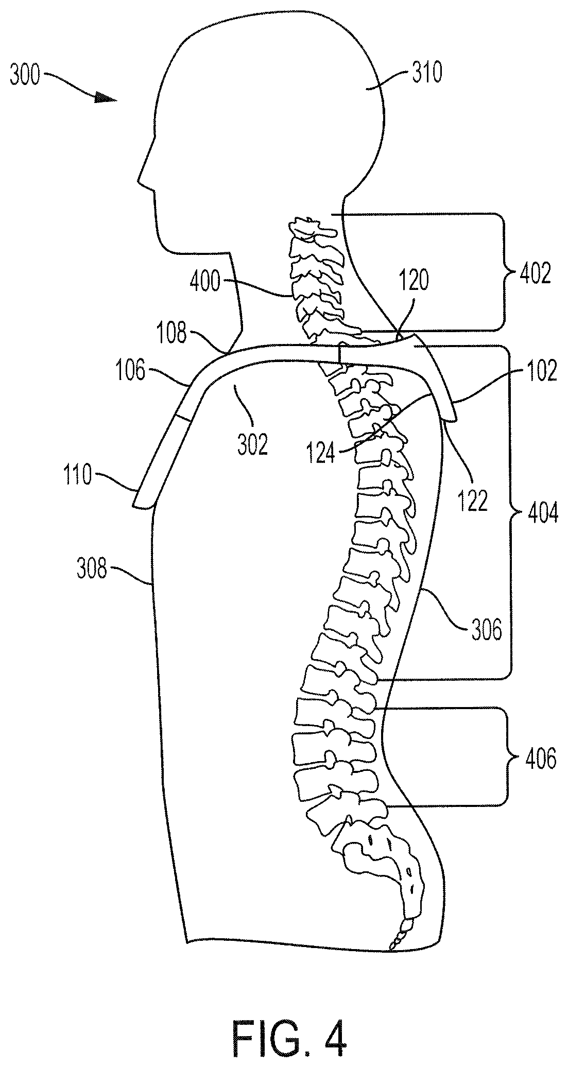
The neck portion 102 may include a top edge or inner edge 120 and a bottom edge or outer edge 122. The inner edge 120 may correspond to an edge that is nearer a center of the wearable computing device 100 than the outer edge 122. When the wearable computing device 100 is worn by a user, as shown in FIG. 3, the inner edge 120 may be nearer to a head of the user than the outer edge 122.
The neck portion 102 may also include a contact surface 124 and an exposed surface 126. The exposed surface 126 may be on an opposite side of the neck portion 102 from the contact surface 124. When the wearable computing device 100 is worn by a user, as shown in FIG. 3, the contact surface 124 may be in contact with a neck or a back of the user and the exposed surface 126 may be exposed to the environment. The contact surface 124 and/or the exposed surface 126 may refer to the neck portion 102 and/or to the entire wearable computing device 100.
The wearable computing device 100 may include multiple features for providing situational awareness to a user. For example, the wearable computing device 100 may provide assistance to a blind user by providing information to the blind user regarding objects in the environment, providing navigation instructions to the blind user, or the like.
The wearable computing device 100 may include one or more input devices for receiving input. The input devices may be used to receive user input, may detect data corresponding to the environment of the user, may receive a communication signal, or the like. For example, the wearable computing device 100 may include one or more buttons 128 for receiving user input. In some embodiments, a user may select a mode of operation of the wearable computing device 100 via the one or more buttons 128.
The wearable computing device 100 may also include one or more camera 130, such as a single camera, a stereo pair of cameras, a wide angle camera, or the like. The camera 130 may detect image data corresponding to the environment of the user.
The wearable computing device 100 may also include one or more output devices for providing output data to the user. The output devices may provide audio feedback, haptic feedback, visual feedback, or the like to the user. For example, the wearable computing device 100 may include a first output unit 132A and a second output unit 132B. The first output unit 132A and the second output unit 132B may each provide audio and haptic output. In that regard, the first output unit 132A and the second output unit 132B may together provide stereo feedback to the user. For example, the first output unit 132A and the second output unit 132B may each output audio data providing an identification of an object in the environment. As another example, the first output unit 132A and the second output unit 132B may provide navigation instructions via audio feedback and/or via stereo haptic feedback.
The wearable computing device 100 may include a mobile processor 134 and a memory 136. In some embodiments, the neck portion 102 defines a cavity in which the mobile processor 134 and/or the memory 136 are positioned. The memory 136 may include any memory for storing non-transitory data including instructions to be performed by the mobile processor 134. The mobile processor 134 may receive input data from the buttons 128 and/or the camera 130. The mobile processor 134 may then determine output data based on the input data and cause the first output unit 132A and the second output unit 132B to output the output data.
The wearable computing device 100 may operate in four modes: explorer mode, scan mode, find mode and capture mode. Each of the buttons 128 may correspond to one mode. For example, one button may correspond to the explorer mode and another button may correspond to the scan mode.
While in the explorer mode, the wearable computing device 100 provides data to the user associated with the surroundings of the user. In some embodiments, the wearable computing device 100 may describe data detected by the camera 130. The data may include predefined data, such as hazard data, whether a friend of the user is passing by, whether a user's favorite restaurant is detected, etc.
While in the scan mode, the wearable computing device 100 may describe everything that is in the field of view of the camera 130. For example, the wearable computing device 100 may describe everything in the field of view, such as by telling the user that object X is 50 degrees to your left, object Y is at your eleven-o'clock, objects Z and W are directly ahead, or the like.
While in the find mode, the wearable computing device 100 can navigate the user to a desired object, place, person, or the like. The user can provide data about the desired object, place, person, or the like, such as by speaking the name or address of the object, place, person, or the like. The wearable computing device 100 can then determine the location of the object, place, person, or the like and provide navigation directions to the user.
The capture mode may allow the wearable computing device 100 to store its current location in the memory 16 so that it can guide the user back to the same location at a later time. The capture mode may include 2 instructions--capture and return. Capture stores the location information (and possibly any obstacles that may arise during a return trip to the position) while return causes the wearable computing device 100 to provide navigation instructions to the user for a return to the location. In various embodiments, a single press of the capture button may indicate the capture instruction and a double click indicates the return instruction.
The wearable computing device 100 may be worn for a relatively long period of time. In that regard, it is desirable for the wearable computing device 100 to be comfortable when worn by a user. It is been shown that comfort of a necklace is increased when pressure on one or more vertebra is decreased. Thus, the neck portion 102 of the wearable computing device 100 includes features for more evenly distributing the weight of the wearable computing device 100 on the user and for decreasing pressure applied to any one or more vertebra by the wearable computing device 100.
One such feature is that the neck portion 102 curves from the first end 116 to the second end 118 to extend around at least a portion of a neck of the user. The neck portion 102 includes a longitudinal axis 138 that may be substantially perpendicular to a longitudinal axis of the first side portion 104 and the second side portion 106. The neck portion 102 may be curved from the longitudinal axis in order to connect with the first side portion 104 and the second side portion 106 while maintaining curvature allowing it to extend around the neck.
The neck portion 102 also includes a width 140 extending from the inner edge 120 to the outer edge 122. Thus, the contact surface 124 may be in contact with the user along the width 140 of the neck portion 102. At least a portion of the contact surface 124 may be bowed outward (i.e., bowed towards the exposed surface 126), such that a concave cavity is defined by the contact surface 124. This bowing of the contact surface 124 results in a curvature that follows a curvature of a spine of the user. For example, the curvature of the contact surface 124 may resemble the curvature from a cervical portion of the spine to a thoracic portion of the spine.
Turning to FIG. 2A, a close-up view of the neck portion 102 illustrates the curvature of the neck portion 102. In particular, FIG. 2A illustrates the curvature of the neck portion 102 from the first end 116 to the second end 118. This curvature may result in the neck portion 102 having a substantially "U" shape from the first side portion 104 to the second side portion 106.
The neck portion 102 may have a center portion 200 positioned between the first end 116 and the second end 118 and extending along the width 140. As shown, the curvature of the neck portion 102 from the inner edge 120 to the outer edge 122 may occur along the width 140 at the center portion 200 of the neck portion 102. In that regard, when the wearable computing device 100 is worn, the contact surface 124 along the center portion 200 may rest flush with the user's spine. This curvature reduces an amount of force applied by the neck portion 102 to any one or more vertebra of the user, thus increasing comfort of the wearable computing device 100.
The neck portion 102 may also include a padding 202 that defines the contact surface 124. The padding 202 may be coupled to a casing of the neck portion 102 and may further distribute the weight of the wearable computing device 100. The padding 202 may include material such as silicon, foam, rubber, or any other material capable of providing cushioning or padding.
Turning to FIG. 2B, a neck portion 252 of another wearable computing device 250 may include different features than the neck portion 102 of FIG. 2A. The neck portion 252 has a first end 254, a second end 256, and a curvature between the first end 254 and the second end 256. The neck portion 252 may also have a curvature from an inner edge to an outer edge. The neck portion 252 may include padding having different features than the padding 202 of FIG. 2B. For example, the neck portion 252 may include a first padding 264 and a second padding 266.
The first padding 264 may span from the first end 254 to a first location 260 positioned away from a halfway point 258 of the neck portion 252. The second padding 266 may span from the second end 256 to a second location 262 positioned away from the halfway point 258 of the neck portion 252.
No padding may exist between the first location 260 and the second location 262. When the wearable computing device 250 is worn, the first padding 264 and the second padding 266 may contact the user's neck, back, and/or shoulders. However, because no padding exists between the first location 260 and the second location 262, the neck portion 252 may not contact the spine of the user or may make minimal contact with the spine of the user. Thus, use of the first padding 264 and the second padding 266 may reduce pressure applied to the user's spine by the neck portion 252 even more so than the design of the neck portion 102 of FIG. 2A.
Turning now to FIG. 3, the wearable computing device 100 is shown as worn by a user 300. As shown, the neck portion 102 at least partially rests on a neck 304 and/or a back 306 of the user 300. The inner edge 120 of the neck portion 102 is positioned higher on the back 306 of the user 300 than the outer edge 122. Thus, the inner edge 120 is positioned nearer to a head 310 of the user 300 than the outer edge 122. In some embodiments, the inner edge 120 may be substantially parallel to the shoulder 302 of the user 300. Stated differently, the inner edge 120 may be positioned at substantially the same height as the user's shoulder 302.
FIG. 3 illustrates how the curvature of the neck portion 102 from the first end 116 to the second end 118 resembles a curvature of the neck 304 of the user 300. This allows the neck portion 102 to extend from a first side of the neck 304 to a second side of the neck 304. From the first end 116, the first side portion 104 extends from the first end 116 of the neck portion 102 over the shoulder 302 and rests on a front 308 of the user 300.
Referring now to FIG. 4, a cross-sectional view of the wearable computing device 100 as worn on the user 300 is shown. A spine 400 of the user is shown to illustrate how the curvature of the neck portion 102 resembles the curvature of the spine 400. The spine 400 includes a cervical portion 402, a thoracic portion 404, and a lumbar portion 406. The spine 400 has a curvature between the cervical portion 402 and the thoracic portion 404. As shown, the contact surface 124 of the neck portion 102 has a curvature that resembles the curvature of the spine 400 between the cervical portion 402 and the thoracic portion 404. Thus, the curvature of the contact surface 124 reduces an amount of pressure applied to any vertebrae of the spine 400 by the wearable computing device 100 by more evenly distributing contact with the user 300.
As shown, the first flexible portion 108 extends across the shoulder 302 towards the front 308 of the user 300. In some embodiments, the first flexible portion 108 may extend along a portion of the front 308 of the user 300. The first rigid portion 110 may rest on the front 308 of the user 300. In that regard, it may be desirable for the first rigid portion 110 to have a relatively flat contact surface such that it may rest on a flat portion of the front 308 of the user 300.
Turning now to FIG. 5, an exploded view of the neck portion 102 illustrates various features of the neck portion 102 for dissipating heat. The neck portion 102 includes a housing 500 having an inner housing 500A and an outer housing 500B. The housing 500 may include metal, plastic, or another rigid material that provides a structure for the components of the neck portion 102. Stated differently, the housing 500 may define a cavity in which components of the neck portion 102 are positioned.
The inner housing 500A may define the contact surface 124 and the outer housing 500B may define the exposed surface 126. In some embodiments, additional padding may be coupled to the contact surface 124 of the inner housing 500A, thus creating a new contact surface that includes the padding.
A printed circuit board (PCB) mount 502 may be positioned within the housing 500. In some embodiments, the PCB mount 502 may be coupled to the inner housing 500A. The PCB mount 502 may include metal, plastic, or another rigid material on which a PCB may be mounted.
A motherboard 504 may include the mobile processor 134 and the memory 136 positioned on and electrically coupled via a PCB 506. The motherboard 504 may be mounted on the PCB mount 502. For example, the motherboard 504 may be coupled to the PCB mount 502 via a snap-fit connection, a press-fit connection, fasteners, or the like.
Because the mobile processor 134 may perform computation-heavy social and environmental awareness functions, it may generate a relatively large amount of heat during operation. It is desirable to dissipate this heat away from the neck portion 102 in order to increase comfort of the user. Thus, the neck portion 102 may include various features for dissipating the heat generated by the mobile processor 134.
The neck portion 102 may include a thermal pad 508 that is coupled to the mobile processor 134. The thermal pad 508 may include a material having a relatively low resistance that is capable of transferring heat. The thermal pad 508 may partially or fully contact a surface of the mobile processor 134.
A pipe 510 may be coupled to the thermal pad 508 and may receive heat from the mobile processor 134 via the thermal pad 508. The pipe 510 may include a metal, such as copper. In that regard, the pipe 510 may have a relatively low resistance and be capable of transferring heat.
A heat spreader 512 may be coupled to the pipe 510 via thermal paste (not shown). The thermal paste may include any spreadable material capable of conducting heat. The heat spreader 512 may include any material capable of conducting heat. For example, the heat spreader 512 may include a metal such as aluminum, copper, or the like. The heat spreader 512 may receive heat from the mobile processor 134 via the thermal pad 508, the pipe 510, and the thermal paste.
The heat spreader 512 may have a relatively large surface area. In that regard, heat received by the heat spreader 512 may be dissipated, or spread, into the atmosphere and/or to the outer housing 500B from various surfaces of the heat spreader 512. Because the heat spreader 512 has a relatively large surface area, heat may be distributed over a relatively large area. This reduces the likelihood of any single location of the neck portion 102 having a relatively high temperature.
Exemplary embodiments of the methods/systems have been disclosed in an illustrative style. Accordingly, the terminology employed throughout should be read in a non-limiting manner. Although minor modifications to the teachings herein will occur to those well versed in the art, it shall be understood that what is intended to be circumscribed within the scope of the patent warranted hereon are all such embodiments that reasonably fall within the scope of the advancement to the art hereby contributed, and that that scope shall not be restricted, except in light of the appended claims and their equivalents.
* * * * *
References
-
applevis.com/guides/braille-ios/introduction-braille-screen-input-ios-8
-
blaize.com
-
ebay.com/itm/MATIN-Made-in-Korea-Neoprene-Canon-DSLR-Camera-Curved-Neck-Strap-6782-/281608526018?hash=item41912d18c2:g:.about.pMAAOSwe-FU6zDa
-
electronicdesign.com/electromechanical/smart-walker-detects-obstaeles
-
members.optuszoo.com.au/aheyew40/pa/pf_blerf.html
-
seeingwithsound.com/ocr.htm
-
newegg.com/Product/Product.aspx?Item=N82E16875982212&Tpk=n82e168759822123pages
-
-
orcam.com
-
yankodesign.com/2008/08/21/voice-stick
-
sciencedaily.com/releases/2008/11/081107072015.htm
-
mightycast.com/#faq
D00000
D00001
D00002
D00003
D00004
D00005
D00006
XML
uspto.report is an independent third-party trademark research tool that is not affiliated, endorsed, or sponsored by the United States Patent and Trademark Office (USPTO) or any other governmental organization. The information provided by uspto.report is based on publicly available data at the time of writing and is intended for informational purposes only.
While we strive to provide accurate and up-to-date information, we do not guarantee the accuracy, completeness, reliability, or suitability of the information displayed on this site. The use of this site is at your own risk. Any reliance you place on such information is therefore strictly at your own risk.
All official trademark data, including owner information, should be verified by visiting the official USPTO website at www.uspto.gov. This site is not intended to replace professional legal advice and should not be used as a substitute for consulting with a legal professional who is knowledgeable about trademark law.