Adapter assembly for interconnecting electromechanical surgical devices and surgical loading units, and surgical systems thereof
Zergiebel , et al. Feb
U.S. patent number 10,561,417 [Application Number 14/550,183] was granted by the patent office on 2020-02-18 for adapter assembly for interconnecting electromechanical surgical devices and surgical loading units, and surgical systems thereof. This patent grant is currently assigned to Covidien LP. The grantee listed for this patent is Covidien LP. Invention is credited to David M. Chowaniec, Anand Subramanian, Ryan V. Williams, Earl M. Zergiebel.


View All Diagrams
| United States Patent | 10,561,417 |
| Zergiebel , et al. | February 18, 2020 |
Adapter assembly for interconnecting electromechanical surgical devices and surgical loading units, and surgical systems thereof
Abstract
The present disclosure relates to adapter assemblies for use with and to electrically and mechanically interconnect electromechanical surgical devices and surgical loading units, and to surgical systems including hand held electromechanical surgical devices and adapter assemblies for connecting surgical loading units to the hand held electromechanical surgical devices.
| Inventors: | Zergiebel; Earl M. (Guilford, CT), Chowaniec; David M. (Rocky Hill, CT), Williams; Ryan V. (New Hartford, CT), Subramanian; Anand (Stamford, CT) | ||||||||||
|---|---|---|---|---|---|---|---|---|---|---|---|
| Applicant: |
|
||||||||||
| Assignee: | Covidien LP (Manfield,
MA) |
||||||||||
| Family ID: | 55177662 | ||||||||||
| Appl. No.: | 14/550,183 | ||||||||||
| Filed: | November 21, 2014 |
Prior Publication Data
| Document Identifier | Publication Date | |
|---|---|---|
| US 20150157321 A1 | Jun 11, 2015 | |
Related U.S. Patent Documents
| Application Number | Filing Date | Patent Number | Issue Date | ||
|---|---|---|---|---|---|
| 61913572 | Dec 9, 2013 | ||||
| Current U.S. Class: | 1/1 |
| Current CPC Class: | H01R 39/08 (20130101); A61B 17/07207 (20130101); A61B 2017/00473 (20130101); A61B 2017/00398 (20130101); A61B 2017/07271 (20130101); Y10T 74/19614 (20150115); A61B 2017/00477 (20130101); A61B 2017/00486 (20130101); A61B 2017/07285 (20130101); A61B 2017/00734 (20130101); A61B 2017/0046 (20130101); A61B 2090/038 (20160201); A61B 2090/064 (20160201); Y10T 74/18576 (20150115) |
| Current International Class: | A61B 17/072 (20060101); H01R 39/08 (20060101); A61B 17/00 (20060101); A61B 90/00 (20160101) |
| Field of Search: | ;227/175.1 |
References Cited [Referenced By]
U.S. Patent Documents
| 2777340 | January 1957 | Hettwer et al. |
| 2957353 | October 1960 | Babacz |
| 3111328 | November 1963 | Di Rito et al. |
| 3695058 | October 1972 | Keith, Jr. |
| 3734515 | May 1973 | Dudek |
| 3759336 | September 1973 | Marcovitz et al. |
| 4162399 | July 1979 | Hudson |
| 4606343 | August 1986 | Conta et al. |
| 4705038 | November 1987 | Sjostrom et al. |
| 4722685 | February 1988 | de Estrada et al. |
| 4823807 | April 1989 | Russell et al. |
| 4874181 | October 1989 | Hsu |
| 5129118 | July 1992 | Walmesley |
| 5129570 | July 1992 | Schulze et al. |
| 5152744 | October 1992 | Krause et al. |
| 5301061 | April 1994 | Nakada et al. |
| 5312023 | May 1994 | Green et al. |
| 5326013 | July 1994 | Green et al. |
| 5350355 | September 1994 | Sklar |
| 5383874 | January 1995 | Jackson et al. |
| 5383880 | January 1995 | Hooven |
| 5389098 | February 1995 | Tsuruta et al. |
| 5395033 | March 1995 | Byrne et al. |
| 5400267 | March 1995 | Denen et al. |
| 5411508 | May 1995 | Bessler et al. |
| 5413267 | May 1995 | Solyntjes et al. |
| 5427087 | June 1995 | Ito et al. |
| 5467911 | November 1995 | Tsuruta et al. |
| 5476379 | December 1995 | Disel |
| 5487499 | January 1996 | Sorrentino et al. |
| 5518163 | May 1996 | Hooven |
| 5518164 | May 1996 | Hooven |
| 5526822 | June 1996 | Burbank et al. |
| 5529235 | June 1996 | Boiarski et al. |
| 5535934 | July 1996 | Boiarski et al. |
| 5535937 | July 1996 | Boiarski et al. |
| 5540375 | July 1996 | Bolanos et al. |
| 5540706 | July 1996 | Aust et al. |
| 5542594 | August 1996 | McKean et al. |
| 5549637 | August 1996 | Crainich |
| 5553675 | September 1996 | Pitzen et al. |
| 5562239 | October 1996 | Boiarski et al. |
| 5564615 | October 1996 | Bishop et al. |
| 5609560 | March 1997 | Ichikawa et al. |
| 5632432 | May 1997 | Schulze et al. |
| 5647526 | July 1997 | Green et al. |
| 5653374 | August 1997 | Young et al. |
| 5658300 | August 1997 | Bito et al. |
| 5667517 | September 1997 | Hooven |
| 5693042 | December 1997 | Boiarski et al. |
| 5704534 | January 1998 | Huitema et al. |
| 5713505 | February 1998 | Huitema |
| 5762603 | June 1998 | Thompson |
| 5766169 | June 1998 | Fritzsch et al. |
| 5779130 | July 1998 | Alesi et al. |
| 5782396 | July 1998 | Mastri et al. |
| 5782397 | July 1998 | Koukline |
| 5797536 | August 1998 | Smith et al. |
| 5820009 | October 1998 | Melling et al. |
| 5863159 | January 1999 | Lasko |
| 5865361 | February 1999 | Milliman et al. |
| 5908427 | June 1999 | McKean et al. |
| 5954259 | September 1999 | Viola et al. |
| 5964774 | October 1999 | McKean et al. |
| 5993454 | November 1999 | Longo |
| 6010054 | January 2000 | Johnson et al. |
| 6017354 | January 2000 | Culp et al. |
| 6032849 | March 2000 | Mastri et al. |
| 6045560 | April 2000 | McKean et al. |
| 6090123 | July 2000 | Culp et al. |
| 6126651 | October 2000 | Mayer |
| 6129547 | October 2000 | Cise et al. |
| 6165169 | December 2000 | Panescu et al. |
| 6171316 | January 2001 | Kovac et al. |
| 6239732 | May 2001 | Cusey |
| 6241139 | June 2001 | Milliman et al. |
| 6264086 | July 2001 | McGuckin, Jr. |
| 6264087 | July 2001 | Whitman |
| 6302311 | October 2001 | Adams et al. |
| 6315184 | November 2001 | Whitman |
| 6321855 | November 2001 | Barnes |
| 6329778 | December 2001 | Culp et al. |
| 6330965 | December 2001 | Milliman et al. |
| 6343731 | February 2002 | Adams et al. |
| 6348061 | February 2002 | Whitman |
| 6368324 | April 2002 | Dinger et al. |
| 6371909 | April 2002 | Hoeg et al. |
| 6434507 | August 2002 | Clayton et al. |
| 6443973 | September 2002 | Whitman |
| 6461372 | October 2002 | Jensen et al. |
| 6488197 | December 2002 | Whitman |
| 6491201 | December 2002 | Whitman |
| 6533157 | March 2003 | Whitman |
| 6537280 | March 2003 | Dinger et al. |
| 6610066 | August 2003 | Dinger et al. |
| 6611793 | August 2003 | Burnside et al. |
| 6645218 | November 2003 | Cassidy et al. |
| 6654999 | December 2003 | Stoddard et al. |
| 6698643 | March 2004 | Whitman |
| 6699177 | March 2004 | Wang et al. |
| 6716233 | April 2004 | Whitman |
| 6743240 | June 2004 | Smith et al. |
| 6783533 | August 2004 | Green et al. |
| 6792390 | September 2004 | Burnside et al. |
| 6793652 | September 2004 | Whitman et al. |
| 6817508 | November 2004 | Racenet et al. |
| 6830174 | December 2004 | Hillstead et al. |
| 6846308 | January 2005 | Whitman et al. |
| 6846309 | January 2005 | Whitman et al. |
| 6849071 | February 2005 | Whitman et al. |
| 6899538 | May 2005 | Matoba |
| 6905057 | June 2005 | Swayze et al. |
| 6959852 | November 2005 | Shelton, IV et al. |
| 6964363 | November 2005 | Wales et al. |
| 6981628 | January 2006 | Wales |
| 6981941 | January 2006 | Whitman et al. |
| 6986451 | January 2006 | Mastri et al. |
| 6988649 | January 2006 | Shelton, IV et al. |
| 6997931 | February 2006 | Sauer et al. |
| 7032798 | April 2006 | Whitman et al. |
| RE39152 | June 2006 | Aust et al. |
| 7055731 | June 2006 | Shelton, IV et al. |
| 7059508 | June 2006 | Shelton, IV et al. |
| 7077856 | July 2006 | Whitman |
| 7111769 | September 2006 | Wales et al. |
| 7122029 | October 2006 | Koop et al. |
| 7140528 | November 2006 | Shelton, IV |
| 7143923 | December 2006 | Shelton, IV et al. |
| 7143925 | December 2006 | Shelton, IV et al. |
| 7143926 | December 2006 | Shelton, IV et al. |
| 7147138 | December 2006 | Shelton, IV |
| 7172104 | February 2007 | Scirica et al. |
| 7225964 | June 2007 | Mastri et al. |
| 7238021 | July 2007 | Johnson |
| 7246734 | July 2007 | Shelton, IV |
| 7328828 | February 2008 | Ortiz et al. |
| 7364061 | April 2008 | Swayze et al. |
| 7380695 | June 2008 | Doll et al. |
| 7380696 | June 2008 | Shelton, IV et al. |
| 7404508 | July 2008 | Smith et al. |
| 7407078 | August 2008 | Shelton, IV et al. |
| 7416101 | August 2008 | Shelton, IV et al. |
| 7419080 | September 2008 | Smith et al. |
| 7422139 | September 2008 | Shelton, IV et al. |
| 7431189 | October 2008 | Shelton, IV et al. |
| 7441684 | October 2008 | Shelton, IV et al. |
| 7448525 | November 2008 | Shelton, IV et al. |
| 7464846 | December 2008 | Shelton, IV et al. |
| 7464847 | December 2008 | Viola et al. |
| 7464849 | December 2008 | Shelton, IV et al. |
| 7481347 | January 2009 | Roy |
| 7481824 | January 2009 | Boudreaux et al. |
| 7487899 | February 2009 | Shelton, IV et al. |
| 7549564 | June 2009 | Boudreaux |
| 7565993 | July 2009 | Milliman et al. |
| 7568603 | August 2009 | Shelton, IV et al. |
| 7575144 | August 2009 | Ortiz et al. |
| 7588175 | September 2009 | Timm et al. |
| 7588176 | September 2009 | Timm et al. |
| 7637409 | December 2009 | Marczyk |
| 7641093 | January 2010 | Doll et al. |
| 7644848 | January 2010 | Swayze et al. |
| 7670334 | March 2010 | Hueil et al. |
| 7673780 | March 2010 | Shelton, IV et al. |
| 7699835 | April 2010 | Lee et al. |
| 7721931 | May 2010 | Shelton, IV et al. |
| 7738971 | June 2010 | Swayze et al. |
| 7740159 | June 2010 | Shelton, IV et al. |
| 7743960 | June 2010 | Whitman et al. |
| 7758613 | July 2010 | Whitman |
| 7766210 | August 2010 | Shelton, IV et al. |
| 7770773 | August 2010 | Whitman et al. |
| 7770775 | August 2010 | Shelton, IV et al. |
| 7793812 | September 2010 | Moore et al. |
| 7799039 | September 2010 | Shelton, IV et al. |
| 7802712 | September 2010 | Milliman et al. |
| 7803151 | September 2010 | Whitman |
| 7819896 | October 2010 | Racenet |
| 7822458 | October 2010 | Webster, III et al. |
| 7845534 | December 2010 | Viola et al. |
| 7845537 | December 2010 | Shelton, IV et al. |
| 7857185 | December 2010 | Swayze et al. |
| 7870989 | January 2011 | Viola et al. |
| 7905897 | March 2011 | Whitman et al. |
| 7918230 | April 2011 | Whitman et al. |
| 7922061 | April 2011 | Shelton, IV et al. |
| 7922719 | April 2011 | Ralph et al. |
| 7947034 | May 2011 | Whitman |
| 7951071 | May 2011 | Whitman et al. |
| 7954682 | June 2011 | Giordano et al. |
| 7959051 | June 2011 | Smith et al. |
| 7963433 | June 2011 | Whitman et al. |
| 7967178 | June 2011 | Scirica et al. |
| 7967179 | June 2011 | Olson et al. |
| 7992758 | August 2011 | Whitman et al. |
| 8016178 | September 2011 | Olson et al. |
| 8016855 | September 2011 | Whitman et al. |
| 8020743 | September 2011 | Shelton, IV |
| 8025199 | September 2011 | Whitman et al. |
| 8035487 | October 2011 | Malackowski |
| 8052024 | November 2011 | Viola et al. |
| 8056787 | November 2011 | Boudreaux et al. |
| 8114118 | February 2012 | Knodel et al. |
| 8132705 | March 2012 | Viola et al. |
| 8152516 | April 2012 | Harvey et al. |
| 8157150 | April 2012 | Viola et al. |
| 8157151 | April 2012 | Ingmanson et al. |
| 8182494 | May 2012 | Yencho et al. |
| 8186555 | May 2012 | Shelton, IV et al. |
| 8186587 | May 2012 | Zmood et al. |
| 8220367 | July 2012 | Hsu |
| 8235273 | August 2012 | Olson et al. |
| 8241322 | August 2012 | Whitman et al. |
| 8245898 | August 2012 | Smith et al. |
| 8272554 | September 2012 | Whitman et al. |
| 8292150 | October 2012 | Bryant |
| 8292888 | October 2012 | Whitman |
| 8303581 | November 2012 | Arts et al. |
| 8342379 | January 2013 | Whitman et al. |
| 8348855 | January 2013 | Hillely et al. |
| 8353440 | January 2013 | Whitman et al. |
| 8357144 | January 2013 | Whitman et al. |
| 8365633 | February 2013 | Simaan et al. |
| 8365972 | February 2013 | Aranyi et al. |
| 8371492 | February 2013 | Aranyi et al. |
| 8372057 | February 2013 | Cude et al. |
| 8391957 | March 2013 | Carlson et al. |
| 8424739 | April 2013 | Racenet et al. |
| 8454585 | June 2013 | Whitman |
| 8505802 | August 2013 | Viola et al. |
| 8517241 | August 2013 | Nicholas et al. |
| 8551076 | October 2013 | Duval et al. |
| 8561871 | October 2013 | Rajappa et al. |
| 8623000 | January 2014 | Humayun et al. |
| 8632463 | January 2014 | Drinan et al. |
| 8647258 | February 2014 | Aranyi et al. |
| 8657174 | February 2014 | Yates et al. |
| 8657177 | February 2014 | Scirica et al. |
| 8672206 | March 2014 | Aranyi et al. |
| 8696552 | April 2014 | Whitman |
| 8708213 | April 2014 | Shelton, IV et al. |
| 8752749 | June 2014 | Moore et al. |
| 8758391 | June 2014 | Swayze et al. |
| 8806973 | August 2014 | Ross et al. |
| 8851355 | October 2014 | Aranyi et al. |
| 8858571 | October 2014 | Shelton, IV et al. |
| 8875972 | November 2014 | Weisenburgh, II et al. |
| 8893946 | November 2014 | Boudreaux et al. |
| 8899462 | December 2014 | Kostrzewski et al. |
| 8939344 | January 2015 | Olson et al. |
| 8960519 | February 2015 | Whitman et al. |
| 8961396 | February 2015 | Azarbarzin et al. |
| 8967443 | March 2015 | McCuen |
| 8968276 | March 2015 | Zemlok et al. |
| 8968337 | March 2015 | Whitfield et al. |
| 8992422 | March 2015 | Spivey et al. |
| 9064653 | June 2015 | Prest et al. |
| 9113875 | August 2015 | Viola et al. |
| 9216013 | December 2015 | Scirica et al. |
| 9282961 | March 2016 | Whitman et al. |
| 9282963 | March 2016 | Bryant |
| 9295522 | March 2016 | Kostrzewski |
| 9307986 | April 2016 | Hall et al. |
| 2001/0031975 | October 2001 | Whitman et al. |
| 2002/0049454 | April 2002 | Whitman et al. |
| 2002/0165541 | November 2002 | Whitman |
| 2003/0038938 | February 2003 | Jung et al. |
| 2003/0165794 | September 2003 | Matoba |
| 2004/0010258 | January 2004 | Carusillo |
| 2004/0111012 | June 2004 | Whitman |
| 2004/0133189 | July 2004 | Sakurai |
| 2004/0176751 | September 2004 | Weitzner et al. |
| 2004/0193146 | September 2004 | Lee et al. |
| 2005/0131442 | June 2005 | Yachia et al. |
| 2006/0089628 | April 2006 | Whitman |
| 2006/0142656 | June 2006 | Malackowski et al. |
| 2006/0142740 | June 2006 | Sherman et al. |
| 2006/0142744 | June 2006 | Boutoussov |
| 2006/0259073 | November 2006 | Miyamoto et al. |
| 2006/0278680 | December 2006 | Viola et al. |
| 2007/0023476 | February 2007 | Whitman et al. |
| 2007/0023477 | February 2007 | Whitman et al. |
| 2007/0027468 | February 2007 | Wales et al. |
| 2007/0027469 | February 2007 | Smith et al. |
| 2007/0029363 | February 2007 | Popov |
| 2007/0055219 | March 2007 | Whitman |
| 2007/0084897 | April 2007 | Shelton et al. |
| 2007/0102472 | May 2007 | Shelton |
| 2007/0152014 | July 2007 | Gillum et al. |
| 2007/0175947 | August 2007 | Ortiz et al. |
| 2007/0175949 | August 2007 | Shelton et al. |
| 2007/0175950 | August 2007 | Shelton et al. |
| 2007/0175951 | August 2007 | Shelton et al. |
| 2007/0175955 | August 2007 | Shelton et al. |
| 2007/0175961 | August 2007 | Shelton et al. |
| 2008/0029570 | February 2008 | Shelton et al. |
| 2008/0029573 | February 2008 | Shelton et al. |
| 2008/0029574 | February 2008 | Shelton et al. |
| 2008/0029575 | February 2008 | Shelton et al. |
| 2008/0058801 | March 2008 | Taylor et al. |
| 2008/0109012 | May 2008 | Falco et al. |
| 2008/0110958 | May 2008 | McKenna et al. |
| 2008/0167736 | July 2008 | Swayze et al. |
| 2008/0185419 | August 2008 | Smith et al. |
| 2008/0188841 | August 2008 | Tomasello et al. |
| 2008/0197167 | August 2008 | Viola et al. |
| 2008/0208195 | August 2008 | Shores et al. |
| 2008/0237296 | October 2008 | Boudreaux et al. |
| 2008/0251561 | October 2008 | Eades et al. |
| 2008/0255413 | October 2008 | Zemlok et al. |
| 2008/0255607 | October 2008 | Zemlok |
| 2008/0262654 | October 2008 | Omori et al. |
| 2008/0308603 | December 2008 | Shelton et al. |
| 2009/0090763 | April 2009 | Zemlok et al. |
| 2009/0099876 | April 2009 | Whitman |
| 2009/0105750 | April 2009 | Price et al. |
| 2009/0108048 | April 2009 | Zemlok |
| 2009/0138006 | May 2009 | Bales et al. |
| 2009/0171147 | July 2009 | Lee et al. |
| 2009/0182193 | July 2009 | Whitman et al. |
| 2009/0209990 | August 2009 | Yates et al. |
| 2009/0254094 | October 2009 | Knapp et al. |
| 2010/0069942 | March 2010 | Shelton, IV |
| 2010/0193568 | August 2010 | Scheib et al. |
| 2010/0211053 | August 2010 | Ross et al. |
| 2010/0225073 | September 2010 | Porter et al. |
| 2011/0006101 | January 2011 | Hall et al. |
| 2011/0017801 | January 2011 | Zemlok et al. |
| 2011/0071508 | March 2011 | Duval et al. |
| 2011/0077673 | March 2011 | Grubac et al. |
| 2011/0121049 | May 2011 | Malinouskas et al. |
| 2011/0125138 | May 2011 | Malinouskas et al. |
| 2011/0139851 | June 2011 | McCuen |
| 2011/0155783 | June 2011 | Rajappa et al. |
| 2011/0155786 | June 2011 | Shelton, IV |
| 2011/0172648 | July 2011 | Jeong |
| 2011/0174099 | July 2011 | Ross |
| 2011/0204119 | August 2011 | McCuen |
| 2011/0218522 | September 2011 | Whitman |
| 2011/0253765 | October 2011 | Nicholas et al. |
| 2011/0276057 | November 2011 | Conlon et al. |
| 2011/0290854 | December 2011 | Timm et al. |
| 2011/0295242 | December 2011 | Spivey et al. |
| 2011/0295269 | December 2011 | Swensgard et al. |
| 2012/0000962 | January 2012 | Racenet et al. |
| 2012/0074199 | March 2012 | Olson et al. |
| 2012/0089131 | April 2012 | Zemlok |
| 2012/0104071 | May 2012 | Bryant |
| 2012/0116368 | May 2012 | Viola |
| 2012/0143002 | June 2012 | Aranyi et al. |
| 2012/0172924 | July 2012 | Allen, IV |
| 2012/0223121 | September 2012 | Viola et al. |
| 2012/0245428 | September 2012 | Smith et al. |
| 2012/0253329 | October 2012 | Zemlok |
| 2012/0310220 | December 2012 | Malkowski et al. |
| 2012/0323226 | December 2012 | Chowaniec et al. |
| 2012/0330285 | December 2012 | Hartoumbekis et al. |
| 2013/0018361 | January 2013 | Bryant |
| 2013/0093149 | April 2013 | Saur et al. |
| 2013/0098966 | April 2013 | Kostrzewski et al. |
| 2013/0098968 | April 2013 | Aranyi et al. |
| 2013/0098969 | April 2013 | Scirica et al. |
| 2013/0181035 | July 2013 | Milliman |
| 2013/0184704 | July 2013 | Beardsley et al. |
| 2013/0214025 | August 2013 | Zemlok et al. |
| 2013/0240596 | September 2013 | Whitman |
| 2013/0274722 | October 2013 | Kostrzewski et al. |
| 2013/0282052 | October 2013 | Aranyi et al. |
| 2013/0292451 | November 2013 | Viola et al. |
| 2013/0313304 | November 2013 | Shelton, IV et al. |
| 2013/0317486 | November 2013 | Nicholas et al. |
| 2013/0319706 | December 2013 | Nicholas et al. |
| 2013/0324978 | December 2013 | Nicholas et al. |
| 2013/0324979 | December 2013 | Nicholas et al. |
| 2013/0334281 | December 2013 | Williams |
| 2014/0012236 | January 2014 | Williams et al. |
| 2014/0012237 | January 2014 | Pribanic et al. |
| 2014/0012289 | January 2014 | Snow et al. |
| 2014/0025046 | January 2014 | Williams et al. |
| 2014/0110455 | April 2014 | Ingmanson et al. |
| 2014/0144970 | May 2014 | Aranyi et al. |
| 2014/0207125 | July 2014 | Applegate et al. |
| 2014/0207182 | July 2014 | Zergiebel et al. |
| 2014/0207185 | July 2014 | Goble et al. |
| 2014/0236173 | August 2014 | Scirica et al. |
| 2014/0236174 | August 2014 | Williams et al. |
| 2014/0276932 | September 2014 | Williams et al. |
| 2014/0299647 | October 2014 | Scirica et al. |
| 2014/0303668 | October 2014 | Nicholas et al. |
| 2014/0358129 | December 2014 | Zergiebel et al. |
| 2014/0361068 | December 2014 | Aranyi et al. |
| 2014/0373652 | December 2014 | Zergiebel et al. |
| 2015/0048144 | February 2015 | Whitman |
| 2015/0076205 | March 2015 | Zergiebel |
| 2015/0080912 | March 2015 | Sapre |
| 2015/0157321 | June 2015 | Zergiebel et al. |
| 2015/0164502 | June 2015 | Richard et al. |
| 2015/0272577 | October 2015 | Zemlok et al. |
| 2015/0297199 | October 2015 | Nicholas et al. |
| 2015/0303996 | October 2015 | Calderoni |
| 2015/0320420 | November 2015 | Penna et al. |
| 2015/0327850 | November 2015 | Kostrzewski |
| 2015/0342601 | December 2015 | Williams et al. |
| 2015/0342603 | December 2015 | Zergiebel et al. |
| 2015/0374366 | December 2015 | Zergiebel et al. |
| 2015/0374370 | December 2015 | Zergiebel et al. |
| 2015/0374371 | December 2015 | Richard et al. |
| 2015/0374372 | December 2015 | Zergiebel et al. |
| 2015/0374449 | December 2015 | Chowaniec et al. |
| 2015/0380187 | December 2015 | Zergiebel et al. |
| 2016/0095585 | April 2016 | Zergiebel et al. |
| 2016/0095596 | April 2016 | Scirica et al. |
| 2016/0106406 | April 2016 | Cabrera et al. |
| 2016/0113648 | April 2016 | Zergiebel et al. |
| 2016/0113649 | April 2016 | Zergiebel et al. |
| 101856251 | Oct 2010 | CN | |||
| 1759652 | Mar 2007 | EP | |||
| 1908412 | Apr 2008 | EP | |||
| 1917929 | May 2008 | EP | |||
| 1952769 | Aug 2008 | EP | |||
| 2044890 | Apr 2009 | EP | |||
| 2090247 | Aug 2009 | EP | |||
| 2245994 | Nov 2010 | EP | |||
| 2329773 | Jun 2011 | EP | |||
| 2377472 | Oct 2011 | EP | |||
| 2446834 | May 2012 | EP | |||
| 2581055 | Apr 2013 | EP | |||
| 2612609 | Jul 2013 | EP | |||
| 2668910 | Dec 2013 | EP | |||
| 2722011 | Apr 2014 | EP | |||
| 2815705 | Dec 2014 | EP | |||
| 2823771 | Jan 2015 | EP | |||
| 2881046 | Jun 2015 | EP | |||
| 2861574 | May 2005 | FR | |||
| 20120022521 | Mar 2012 | KR | |||
| 2008/121234 | Oct 2008 | WO | |||
| 20091039506 | Mar 2009 | WO | |||
| 20091039510 | Mar 2009 | WO | |||
Other References
|
Extended European Search Report corresponding to International Application No. EP 15 15 1076.5 dated Apr. 22, 2015. cited by applicant . Japanese Office Action corresponding to International Application No. JP 2011-084092 dated Jan. 14, 2016. cited by applicant . Extended European Search Report corresponding to International Application No. EP 12 19 7970.2 dated Jan. 28, 2016. cited by applicant . Chinese Office Action corresponding to International Application No. CN 201210560638.1 dated Oct. 21, 2015. cited by applicant . European Office Action corresponding to International Application No. EP 14 15 9056.2 dated Oct. 26, 2015. cited by applicant . Australian Examination Report No. 1 corresponding to International Application No. AU 2015200153 dated Dec. 11, 2015. cited by applicant . Australian Examination Report No. 1 corresponding to International Application No. AU 2014204542 dated Jan. 7, 2016. cited by applicant . Chinese Office Action corresponding to International Application No. CN 201310125449.6 dated Feb. 3, 2016. cited by applicant . Extended European Search Report corresponding to International Application No. EP 15 19 0245.9 dated Jan. 28, 2016. cited by applicant . Extended European Search Report corresponding to International Application No. EP 15 16 7793.7 dated Apr. 5, 2016. cited by applicant . European Office Action corresponding to International Application No. EP 14 18 4882.0 dated Apr. 25, 2016. cited by applicant . International Search Report and Written Opinion corresponding to Int'l Appln. No. PCT/US2015/051837, dated Dec. 21, 2015. cited by applicant . Extended European Search Report corresponding to International Application No. EP 14 19 7563.1 dated Aug. 5, 2015. cited by applicant . Partial European Search Report corresponding to International Application No. EP 15 19 0643.5 dated Feb. 26, 2016. cited by applicant . Extended European Search Report corresponding to International Application No. EP 15 16 6899.3 dated Feb. 3, 2016. cited by applicant . Extended European Search Report corresponding to International Application No. EP 14 19 9783.3 dated Dec. 22, 2015. cited by applicant . Extended European Search Report corresponding to International Application No. EP 15 17 3807.7 dated Nov. 24, 2015. cited by applicant . Extended European Search Report corresponding to International Application No. EP 15 19 0760.7 dated Apr. 1, 2016. cited by applicant . Extended European Search Report corresponding to International Application No. EP 15 17 3803.6 dated Nov. 24, 2015. cited by applicant . Extended European Search Report corresponding to International Application No. EP 15 17 3804.4 dated Nov. 24, 2015. cited by applicant . Extended European Search Report corresponding to International Application No. EP 15 18 8539.9 dated Feb. 17, 2016. cited by applicant . Extended European Search Report corresponding to International Application No. EP 15 17 3910.9 dated Nov. 13, 2015. cited by applicant . European Office Action corresponding to International Application No. EP 14 15 2236.7 dated Aug. 11, 2015. cited by applicant . Extended European Search Report corresponding to International Application No. EP 15 18 4915.5 dated Jan. 5, 2016. cited by applicant . Extended European Search Report corresponding to counterpart Int'l Appln. No. EP 16 18 3520.2 dated May 3, 2017. cited by applicant . Extended European Search Report corresponding to EP 14 19 6833.9 dated Jul. 23, 2015; 11 pp. cited by applicant . European Office Action corresponding to counterpart Int'l Appln. No. EP 14 19 6704.2 dated Oct. 28, 2016. cited by applicant . Extended European Search Report corresponding to counterpart International Application No. EP 14 19 6704.2, dated Sep. 24, 2015; (11 pp.). cited by applicant . Partial European Search Report corresponding to EP 14196833.9 dated May 6, 2015; 6 pages. cited by applicant . Partial European Search Report corresponding to EP 14196704.2 dated May 11, 2015; 6 pages. cited by applicant . Partial European Search Report corresponding to counterpart Int'l Appln. No. EP 16 18 3520.2 dated Dec. 13, 2016. cited by applicant . Chinese First Office Action corresponding to counterpart Patent Appln. CN 2014107511525 dated Apr. 4, 2018. cited by applicant . Australian Office Action corresponding to counterpart Patent Appln. AU 201468210 dated Jul. 27, 2018. cited by applicant . Japanese Final Office Action corresponding to counterpart Patent Application JP 2014-247812 dated Jan. 18, 2019. cited by applicant . Chinese Second Office Action corresponding to counterpart Patent Appln. CN 201410751152.5 dated Dec. 10, 2018. cited by applicant . Australian Office Action dated Jun. 13, 2019 corresponding to counterpart Patent Application AU 2019201734. cited by applicant . Extended European Search Report corresponding to counterpart Patent Appln. EP 17 17 1082.5 dated Oct. 5, 2017. cited by applicant . Japanese Office Action corresponding to counterpart Patent Appln. JP 2014-247811 dated Aug. 30, 2018. cited by applicant . Chinese First Office Action corresponding to counterpart Chinese patent application CN 2014107508838 dated Feb. 24, 2018. cited by applicant. |
Primary Examiner: Lopez; Michelle
Assistant Examiner: Rushing-Tucker; Chinyere J
Parent Case Text
CROSS-REFERENCE TO RELATED APPLICATIONS
This application claims the benefit of and priority to U.S. Provisional Patent Application No. 61/913,572, filed Dec. 9, 2013, the entire disclosure of which is incorporated by reference herein.
Claims
What is claimed is:
1. An electromechanical surgical system configured for selective connection with a surgical loading unit in order to actuate the loading unit to perform at least one function, the loading unit including a plurality of axially translatable drive members; the surgical system comprising: a handle-held electromechanical surgical device including: a housing; and a plurality of rotatable drive shafts supported in, and projecting from the housing; and an adapter assembly selectively connectable between the housing of the surgical device and the loading unit, the adapter assembly comprising: a housing configured and adapted for connection with the surgical device and to be in operative communication with each of the plurality of rotatable drive shafts of the surgical device; an outer tube having a proximal end supported by the housing and a distal end configured and adapted for connection with the loading unit, wherein the distal end of the outer tube is in operative communication with each of the plurality of axially translatable drive members of the loading unit; and three force/rotation transmitting/converting assemblies, each of the three force/rotation transmitting/converting assemblies configured for interconnecting a respective one of the plurality of rotatable drive shafts of the surgical device and a respective one of the plurality of axially translatable drive members of the loading unit, wherein each of the three force/rotation transmitting/converting assemblies includes: a proximal rotation receiving member that is connectable to the respective one of the plurality of rotatable drive shafts of the surgical device, each of the proximal rotation receiving members being arranged in a straight line defining an axis extending in a direction transverse to a longitudinal axis of the adapter assembly; and a distal force transmitting member that is connectable to the respective one of the plurality of axially translatable drive members of the loading unit, each of the distal force transmitting members being connected to each of the proximal rotation receiving members, respectively, in such a manner whereby rotation of the proximal rotation receiving member is converted to axial translation of the distal force transmitting member; wherein the three force/rotation transmitting/converting assemblies converts and transmits a rotation of the respective one of the plurality of rotatable drive shafts of the surgical device to an axial translation of the respective one of the plurality of axially translatable drive members of the loading unit.
2. The surgical system according to claim 1, wherein the three force/rotation transmitting/converting assemblies of the adapter assembly includes a first force/rotation transmitting/converting assembly; wherein the proximal rotation receiving member of the first force/rotation transmitting/converting assembly includes a first proximal drive shaft defining a threaded distal end; and wherein the distal force transmitting member of the first force/rotation transmitting/converting assembly includes a distal drive member threadably connected to the threaded distal end of the first proximal drive shaft.
3. The surgical system according to claim 2, wherein the first proximal drive shaft and the distal drive member of the adapter assembly are axially aligned with one another and with a rotational axis of the respective rotatable drive shaft of the surgical device.
4. The surgical system according to claim 2, wherein rotation of the respective one of the plurality of rotatable drive shafts of the surgical device, associated with the first force/rotation transmitting/converting assembly, results in rotation of the first proximal drive shaft of the first force/rotation transmitting/converting assembly which results in axial translation of the distal drive member of the first force/rotation transmitting/converting assembly of the adapter assembly.
5. The surgical system according to claim 2, wherein the three force/rotation transmitting/converting assemblies of the adapter assembly includes a second force/rotation transmitting/converting assembly; wherein the proximal rotation receiving member of the second force/rotation transmitting/converting assembly includes a second proximal drive shaft defining a threaded distal end; and wherein the distal force transmitting member of the second force/rotation transmitting/converting assembly includes a bearing assembly having an outer race threadably connected to the threaded distal end of the second proximal drive shaft and being non-rotatably disposed within the housing.
6. The surgical system according to claim 5, wherein the bearing assembly of the adapter assembly includes an inner race, and wherein the distal force transmitting member of the second force/rotation transmitting/converting assembly of the adapter assembly includes an articulation bar having a proximal end secured to the inner race of the bearing assembly, and a distal end configured to selectively engage a second axially translatable drive member of the loading unit.
7. The surgical system according to claim 5, wherein at least a portion of the first force/rotation transmitting/converting assembly of the adapter assembly extends through the bearing assembly of the second force/rotation transmitting/converting assembly of the adapter assembly.
8. The surgical system according to claim 7, wherein the articulation bar of the adapter assembly is rotatable about the first force/rotation transmitting/converting assembly.
9. The surgical system according to claim 5, wherein rotation of the respective one of the plurality of rotatable drive shafts of the surgical device, associated with the second force/rotation transmitting/converting assembly of the adapter assembly, results in rotation of the second proximal drive shaft of the second force/rotation transmitting/converting assembly which results in axial translation of the articulation bar of the second force/rotation transmitting/converting assembly.
10. The surgical system according to claim 9, wherein the three force/rotation transmitting/converting assemblies of the adapter assembly includes a third force/rotation transmitting/converting assembly; wherein the proximal rotation receiving member of the third force/rotation transmitting/converting assembly includes a third proximal drive shaft having a spur gear supported on a distal end thereof; and wherein the distal force transmitting member of the third force/rotation transmitting/converting assembly includes a ring gear fixedly supported in the housing and being in gearing connection with the spur gear.
11. The surgical system according to claim 10, wherein rotation of the respective one of the plurality of rotatable drive shafts of the surgical device, associated with the third force/rotation transmitting/converting assembly, results in rotation of the third proximal drive shaft of the third force/rotation transmitting/converting assembly of the adapter assembly which results in rotation of the ring gear of the third force/rotation transmitting/converting assembly.
12. The surgical system according to claim 10, wherein the adapter assembly further comprises an electrical assembly supported within at least one of the housing and the outer tube thereof, the electrical assembly including: a circuit board; at least one contact pin electrically connected to the circuit board and being configured and adapted to selectively electrically connect to a complementary electrical plug of the surgical device; a strain gauge supported on and electrically connected to the circuit board, wherein the first rotatable proximal drive shaft extends through the strain gauge; and a slip ring disposed about the distal drive member of the first force/rotation transmitting/converting assembly, wherein the slip ring is in electrical connection with the circuit board, and wherein the slip ring includes electrical contact supported therein for maintaining electrical contact with at least one electrical component within the adapter assembly.
13. An adapter assembly for selectively interconnecting a surgical loading unit that is configured to perform a function and a surgical device that is configured to actuate the loading unit, the loading unit including a plurality of axially translatable drive members, and the surgical device including a plurality of rotatable drive shafts, the adapter assembly comprising: a housing configured and adapted for connection with the surgical device and to be in operative communication with each of the plurality of rotatable drive shafts of the surgical device; an outer tube having a proximal end supported by the housing and a distal end configured and adapted for connection with the loading unit, wherein the distal end of the outer tube is in operative communication with each of the plurality of axially translatable drive members of the loading unit; three force/rotation transmitting/converting assemblies, each of the three force/rotation transmitting/converting assemblies configured for interconnecting a respective one of the plurality of rotatable drive shafts of the surgical device and a respective one of the plurality of axially translatable drive members of the loading unit, each of the three force/rotation transmitting/converting assemblies including a proximal rotation receiving member that is connectable to the respective one of the plurality of rotatable drive shafts of the surgical device, each of the proximal rotation receiving members being arranged in a straight line defining an axis extending in a direction transverse to a longitudinal axis of the adapter assembly; and an electrical assembly supported within at least one of the housing and the outer tube thereof, the electrical assembly including: a circuit board; at least one contact pin electrically connected to the circuit board and being configured and adapted to selectively electrically connect to a complementary electrical plug of the surgical device; a strain gauge supported on and electrically connected to the circuit board, wherein at least one of the proximal rotation receiving members extends through the strain gauge; and a slip ring disposed about at least a portion of one of the three force/rotation transmitting/converting assemblies, wherein the slip ring is in electrical connection with the circuit board, and wherein the slip ring includes electrical contact supported therein for maintaining electrical contact with at least one electrical component within the adapter assembly.
14. The adapter assembly according to claim 13, wherein the three force/rotation transmitting/converting assemblies further includes: a distal force transmitting member that is connectable to the respective one of the plurality of axially translatable drive members of the loading unit, each of the distal force transmitting member being connected to each of the proximal rotation receiving members, respectively, in such a manner whereby rotation of the proximal rotation receiving member is converted to axial translation of the distal force transmitting member; wherein each of the three force/rotation transmitting/converting assemblies converts and transmits a rotation of the respective one of the plurality of rotatable drive shafts of the surgical device to an axial translation of the respective one of the plurality of axially translatable drive members of the loading unit.
15. An electromechanical surgical system configured for selective connection with a surgical loading unit in order to actuate the loading unit to perform at least one function, the loading unit including a plurality of axially translatable drive members; the surgical system comprising: a handle-held electromechanical surgical device including: a housing; and a plurality of rotatable drive shafts supported in, and projecting from the housing; and an adapter assembly selectively connectable between the housing of the surgical device and the loading unit, the adapter assembly comprising: a housing configured and adapted for connection with the surgical device and to be in operative communication with each of the plurality of rotatable drive shafts of the surgical device; and three force/rotation transmitting/converting assemblies, each of the three force/rotation transmitting/converting assemblies configured for interconnecting a respective one of the plurality of rotatable drive shafts of the surgical device and a respective one of the plurality of axially translatable drive members of the loading unit, wherein each of the three force/rotation transmitting/converting assemblies includes a proximal rotation receiving member that is connectable to the respective one of the plurality of rotatable drive shafts of the surgical device, each of the proximal rotation receiving members being arranged in a straight line defining an axis extending in a direction transverse to a longitudinal axis of the adapter assembly, wherein each of the three force/rotation transmitting/converting assemblies converts and transmits a rotation of the respective one of the plurality of rotatable drive shafts of the surgical device to an axial translation of the respective one of the plurality of axially translatable drive members of the loading unit.
Description
BACKGROUND
1. Technical Field
The present disclosure relates to adapter assemblies for use in surgical systems. More specifically, the present disclosure relates to adapter assemblies for use with and to electrically and mechanically interconnect electromechanical surgical devices and surgical loading units, and to surgical systems including hand held electromechanical surgical devices and adapter assemblies for connecting surgical loading units to the hand held electromechanical surgical devices.
2. Background of Related Art
A number of surgical device manufacturers have developed product lines with proprietary drive systems for operating and/or manipulating electromechanical surgical devices. In many instances the electromechanical surgical devices include a handle assembly, which is reusable, and disposable loading units and/or single use loading units or the like that are selectively connected to the handle assembly prior to use and then disconnected from the handle assembly following use in order to be disposed of or in some instances sterilized for re-use.
In certain instances, an adapter assembly is used to interconnect an electromechanical surgical device with any one of a number of surgical loading units to establish a mechanical and/or electrical connection therebetween. By using an adapter assembly to interconnect the electromechanical surgical device with the surgical loading units, an overall length of this electromechanical surgical system tends to be relatively greater/longer as compared to an electromechanical surgical system not using an adapter assembly. This increased length of the electromechanical surgical system (including an adapter assembly) tends to move a center of gravity of the electromechanical surgical system (including an adapter assembly) relatively distal of a center of gravity of another electromechanical surgical system (not including an adapter assembly).
With the center of gravity being located at a more distal location of the electromechanical surgical system, a torque exerted on the hand, wrist and arm of the user is increased and thus renders use of the electromechanical surgical system tiresome or cumbersome.
Accordingly, a need exists for an adapter assembly that has a relatively shorter length and that reduces the distal displacement of a center of gravity of the electromechanical surgical system.
SUMMARY
The present disclosure relates to adapter assemblies for use with and to electrically and mechanically interconnect electromechanical surgical devices and surgical loading units, and to surgical systems including hand held electromechanical surgical devices and adapter assemblies for connecting surgical loading units to the hand held electromechanical surgical devices.
According to an aspect of the present disclosure, an adapter assembly for selectively interconnecting a surgical loading unit that is configured to perform a function and a surgical device that is configured to actuate the loading unit, is provided. The loading unit may include at least one axially translatable drive member, and the surgical device may include at least one rotatable drive shaft. The adapter assembly includes a housing configured and adapted for connection with the surgical device and to be in operative communication with each rotatable drive shaft of the surgical device; an outer tube having a proximal end supported by the housing and a distal end configured and adapted for connection with the loading unit, wherein the distal end of the outer tube is in operative communication with each of the axially translatable drive member of the loading unit; and the force/rotation transmitting/converting assembly for interconnecting a respective one drive shaft of the surgical device and a respective one axially translatable drive member of the loading unit.
The force/rotation transmitting/converting assembly includes a proximal rotation receiving member that is connectable to a respective rotatable drive shaft of the surgical device; and a distal force transmitting member that is connectable to an axially translatable drive member of the loading unit, the distal force transmitting member being connected to the proximal rotation receiving member in such a manner whereby rotation of the proximal rotation receiving member is converted to axial translation of the distal force transmitting member.
In operation, the force/rotation transmitting/converting assembly converts and transmits a rotation of the first rotatable drive shaft of the surgical device to an axial translation of the first axially translatable drive member of the loading unit.
The force/rotation transmitting/converting assembly may include a first force/rotation transmitting/converting assembly. The proximal rotation receiving member of the first force/rotation transmitting/converting assembly may include a first proximal drive shaft defining a threaded distal end. The distal force transmitting member of the first force/rotation transmitting/converting assembly may include a distal drive member threadably connected to the threaded distal end of the first proximal drive shaft.
The first proximal drive shaft and the distal drive member may be axially aligned with one another and with a rotational axis of the respective rotatable drive shaft of the surgical device.
In use, rotation of the rotatable drive shaft of the surgical device, associated with the first force/rotation transmitting/converting assembly, may result in rotation of the first rotatable drive shaft of the first force/rotation transmitting/converting assembly which may result in axial translation of the distal drive member of the first force/rotation transmitting/converting assembly.
The force/rotation transmitting/converting assembly may include a second force/rotation transmitting/converting assembly. The proximal rotation receiving member of the second force/rotation transmitting/converting assembly may include a second proximal drive shaft defining a threaded distal end. The distal force transmitting member of the second force/rotation transmitting/converting assembly may include a bearing assembly having an outer race threadably connected to the threaded distal end of the second proximal drive shaft and being non-rotatably disposed within the housing.
The bearing assembly may include an inner race. The distal force transmitting member of the second force/rotation transmitting/converting assembly may include an articulation bar having a proximal end secured to the inner race of the bearing assembly, and a distal end configured to selectively engage a second axially translatable drive member of the loading unit.
At least a portion of the first force/rotation transmitting/converting assembly may extend through the bearing assembly of the second force/rotation transmitting/converting assembly.
The articulation bar may be rotatable about the first force/rotation transmitting/converting assembly.
In use, rotation of the rotatable drive shaft of the surgical device, associated with the second force/rotation transmitting/converting assembly, may result in rotation of the second rotatable drive shaft of the second force/rotation transmitting/converting assembly which results in axial translation of the articulation bar of the second force/rotation transmitting/converting assembly.
The force/rotation transmitting/converting assembly may include a third force/rotation transmitting/converting assembly. The proximal rotation receiving member of the third force/rotation transmitting/converting assembly may include a third proximal drive shaft having a spur gear supported on a distal end thereof. The distal force transmitting member of the third force/rotation transmitting/converting assembly may include a ring gear fixedly supported in the housing and being in gearing connection with the spur gear.
In use, rotation of the rotatable drive shaft of the surgical device, associated with the third force/rotation transmitting/converting assembly, may result in rotation of the third rotatable drive shaft of the third force/rotation transmitting/converting assembly which results in rotation of the ring gear of the third force/rotation transmitting/converting assembly.
The adapter assembly may further include an electrical assembly supported within at least one of the housing and the outer tube. The electrical assembly may include a circuit board; and contact pins electrically connected to the circuit board and being configured and adapted to selectively electrically connect to a complementary electrical plug of the surgical device; a strain gauge supported on and electrically connected to the circuit board, wherein the first rotatable proximal drive shaft extends through the strain gauge; and a slip ring disposed about the distal drive member of the first force/rotation transmitting/converting assembly. The slip ring may be in electrical connection with the circuit board, and wherein the slip ring includes electrical contact supported therein for maintaining electrical contact with electrical components within the adapter assembly.
The first proximal drive shaft, the second proximal drive shaft and the third proximal drive shaft may be arranged in a common plane with one another.
According to another aspect of the present disclosure, an electromechanical surgical system is provided that is configured for selective connection with a surgical loading unit in order to actuate the loading unit to perform functions. The loading unit may include at least one axially translatable drive member. The surgical system includes a handle-held electromechanical surgical device including a housing; and at least one rotatable drive shaft supported in the projecting from the housing.
The surgical system further includes an adapter assembly selectively connectable between the housing of the surgical device and the loading unit. The adapter assembly includes a housing configured and adapted for connection with the surgical device and to be in operative communication with each rotatable drive shaft of the surgical device; an outer tube having a proximal end supported by the housing and a distal end configured and adapted for connection with the loading unit, wherein the distal end of the outer tube is in operative communication with each of the axially translatable drive members of the loading unit; and the force/rotation transmitting/converting assemblies for interconnecting a respective drive shafts of the surgical device and the respective axially translatable drive member of the loading unit.
The force/rotation transmitting/converting assembly includes a proximal rotation receiving member that is connectable to a respective rotatable drive shaft of the surgical device; and a distal force transmitting member that is connectable to an axially translatable drive member of the loading unit, the distal force transmitting member being connected to the proximal rotation receiving member in such a manner whereby rotation of the proximal rotation receiving member is converted to axial translation of the distal force transmitting member.
The force/rotation transmitting/converting assembly converts and transmits a rotation of the first rotatable drive shaft of the surgical device to an axial translation of the first axially translatable drive member of the loading unit.
The force/rotation transmitting/converting assembly of the adapter assembly may include a first force/rotation transmitting/converting assembly. The proximal rotation receiving member of the first force/rotation transmitting/converting assembly may include a first proximal drive shaft defining a threaded distal end. The distal force transmitting member of the first force/rotation transmitting/converting assembly may include a distal drive member threadably connected to the threaded distal end of the first proximal drive shaft.
The first proximal drive shaft and the distal drive member of the adapter assembly may be axially aligned with one another and with a rotational axis of the respective rotatable drive shaft of the surgical device.
In use, rotation of the rotatable drive shaft of the surgical device, associated with the first force/rotation transmitting/converting assembly, may result in rotation of the first rotatable drive shaft of the first force/rotation transmitting/converting assembly which results in axial translation of the distal drive member of the first force/rotation transmitting/converting assembly of the adapter assembly.
The force/rotation transmitting/converting assembly of the adapter assembly may include a second force/rotation transmitting/converting assembly. The proximal rotation receiving member of the second force/rotation transmitting/converting assembly may include a second proximal drive shaft defining a threaded distal end. The distal force transmitting member of the second force/rotation transmitting/converting assembly may include a bearing assembly having an outer race threadably connected to the threaded distal end of the second proximal drive shaft and being non-rotatably disposed within the housing.
The bearing assembly of the adapter assembly may include an inner race, and wherein the distal force transmitting member of the second force/rotation transmitting/converting assembly of the adapter assembly may include an articulation bar having a proximal end secured to the inner race of the bearing assembly, and a distal end configured to selectively engage a second axially translatable drive member of the loading unit.
At least a portion of the first force/rotation transmitting/converting assembly of the adapter assembly may extend through the bearing assembly of the second force/rotation transmitting/converting assembly of the adapter assembly.
The articulation bar of the adapter assembly may be rotatable about the first force/rotation transmitting/converting assembly.
In use, rotation of the rotatable drive shaft of the surgical device, associated with the second force/rotation transmitting/converting assembly of the adapter assembly, may result in rotation of the second rotatable drive shaft of the second force/rotation transmitting/converting assembly which may result in axial translation of the articulation bar of the second force/rotation transmitting/converting assembly.
The force/rotation transmitting/converting assembly of the adapter assembly may include a third force/rotation transmitting/converting assembly. The proximal rotation receiving member of the third force/rotation transmitting/converting assembly may include a third proximal drive shaft having a spur gear supported on a distal end thereof. The distal force transmitting member of the third force/rotation transmitting/converting assembly may include a ring gear fixedly supported in the housing and being in gearing connection with the spur gear.
In use, rotation of the rotatable drive shaft of the surgical device, associated with the third force/rotation transmitting/converting assembly, may result in rotation of the third rotatable drive shaft of the third force/rotation transmitting/converting assembly of the adapter assembly which may result in rotation of the ring gear of the third force/rotation transmitting/converting assembly.
The adapter assembly may further include an electrical assembly supported within at least one of the housing and the outer tube thereof. The electrical assembly may include a circuit board; contact pins electrically connected to the circuit board and being configured and adapted to selectively electrically connect to a complementary electrical plug of the surgical device; a strain gauge supported on and electrically connected to the circuit board, wherein the first rotatable proximal drive shaft extends through the strain gauge; and a slip ring disposed about the distal drive member of the first force/rotation transmitting/converting assembly, wherein the slip ring is in electrical connection with the circuit board, and wherein the slip ring includes electrical contact supported therein for maintaining electrical contact with at least one electrical component within the adapter assembly.
The first proximal drive shaft, the second proximal drive shaft and the third proximal drive shaft of the adapter assembly may be arranged in a common plane with one another.
According to a further aspect of the present disclosure, an adapter assembly is provided and includes a housing configured and adapted for connection with the surgical device and to be in operative communication with each rotatable drive shaft of the surgical device; an outer tube having a proximal end supported by the housing and a distal end configured and adapted for connection with the loading unit, wherein the distal end of the outer tube is in operative communication with each of the axially translatable drive member of the loading unit; force/rotation transmitting/converting assembly for interconnecting a respective one drive shaft of the surgical device and a respective one axially translatable drive member of the loading unit; and an electrical assembly supported within the housing and the outer tube thereof.
The electrical assembly includes a circuit board; contact pins electrically connected to the circuit board and being configured and adapted to selectively electrically connect to a complementary electrical plug of the surgical device; a strain gauge supported on and electrically connected to the circuit board, wherein the first rotatable proximal drive shaft extends through the strain gauge; and a slip ring disposed about at least a portion of the first force/rotation transmitting/converting assembly, wherein the slip ring is in electrical connection with the circuit board, and wherein the slip ring includes electrical contact supported therein for maintaining electrical contact with at least one electrical component within the adapter assembly.
The force/rotation transmitting/converting assembly may include a proximal rotation receiving member that is connectable to a respective rotatable drive shaft of the surgical device; and a distal force transmitting member that is connectable to an axially translatable drive member of the loading unit, the distal force transmitting member being connected to the proximal rotation receiving member in such a manner whereby rotation of the proximal rotation receiving member is converted to axial translation of the distal force transmitting member.
In use, the force/rotation transmitting/converting assembly may convert and transmit a rotation of the first rotatable drive shaft of the surgical device to an axial translation of the first axially translatable drive member of the loading unit.
BRIEF DESCRIPTION OF THE DRAWINGS
Embodiments of the present disclosure are described herein with reference to the accompanying drawings, wherein:
FIG. 1A is a perspective view of an adapter assembly, in accordance with an embodiment of the present disclosure, interconnected between an exemplary electromechanical surgical device and an end effector assembly;
FIG. 1B is a perspective view illustrating an attachment of a proximal end of the adapter assembly to a distal end of the electromechanical surgical device;
FIG. 2A is a front, perspective view of the adapter assembly of the present disclosure;
FIG. 2B is a rear, perspective view of the adapter assembly of FIG. 2A;
FIG. 3 is a top plan view of the adapter assembly of FIGS. 2A and 2B;
FIG. 4 is a side, elevational view of the adapter assembly of FIGS. 2A and 2B;
FIG. 5 is a rear, perspective view of the adapter assembly of FIGS. 2A and 2B, with some parts thereof separated;
FIG. 6 is a rear, perspective view of the adapter assembly of FIGS. 2A and 2B, with most parts thereof separated;
FIG. 7 is a perspective view of an articulation assembly of the adapter assembly of FIGS. 2A and 2B;
FIG. 8 is an enlarged, perspective view, with parts separated, of the articulation assembly of FIG. 7;
FIG. 9 is a perspective view of the articulation assembly of FIG. 7, shown in a first orientation;
FIG. 10 is a perspective view of the articulation assembly of FIG. 7, shown in a second orientation;
FIG. 11 is a cross-sectional view as taken along section line 11-11 of FIG. 9;
FIG. 12 is a perspective view of an electrical assembly of the adapter assembly of FIGS. 2A and 2B;
FIG. 13 is a perspective view of the electrical assembly of FIG. 12 shown connected to the core housing of the adapter assembly of FIGS. 2A and 2B;
FIG. 14 is a cross-sectional view as taken along section line 14-14 of FIG. 13;
FIG. 15 is a perspective view of a slip ring cannula or sleeve of the adapter assembly of FIGS. 2A and 2B;
FIG. 16 is an enlarged view of the indicated area of detail of FIG. 2B, illustrating an inner housing assembly of the adapter assembly of FIGS. 2A and 2B;
FIG. 17 is a rear, perspective view of the inner housing assembly of FIG. 16 with an outer knob housing half-section and a proximal cap removed therefrom;
FIG. 18 is a rear, perspective view of the inner housing assembly of FIG. 16 with the outer knob housing, the proximal cap and a bushing plate removed therefrom;
FIG. 19 is a rear, perspective view of the inner housing assembly of FIG. 16 with the outer knob housing, the proximal cap, the bushing plate and an inner housing removed therefrom;
FIG. 20 is a rear, perspective view of the an alternative embodiment of inner housing assembly similar to that shown in FIG. 16 with the outer knob housing and the proximal inner housing removed therefrom;
FIG. 21 is a rear, perspective view of the inner housing assembly of FIG. 20 with the outer knob housing, the proximal inner housing and the articulation assembly removed therefrom;
FIG. 22 is a front, perspective view of the inner housing assembly of FIG. 20 with the outer knob housing, the proximal inner housing and the articulation assembly removed therefrom;
FIG. 23 is a front, perspective view of the inner housing assembly of FIG. 20 with the outer knob housing and the proximal inner housing removed therefrom;
FIG. 24 is a cross-sectional view as taken along section line 24-24 of FIG. 2B;
FIG. 25 is an enlarged view of the indicated area of detail of FIG. 24;
FIG. 26 is an enlarged view of the indicated area of detail of FIG. 24, illustrating a lock button being actuated in a proximal direction;
FIG. 27 is a cross-sectional view as taken along section line 27-27 of FIG. 2B;
FIG. 28 is a cross-sectional view as taken along section line 27-27 of FIG. 2B, illustrating actuation of the articulation assembly in a distal direction;
FIG. 29 is a cross-sectional view as taken along section line 29-29 of FIG. 28;
FIG. 30 is a cross-sectional view as taken along section line 30-30 of FIG. 28;
FIG. 31 is a cross-sectional view as taken along section line 31-31 of FIG. 28;
FIG. 32 is a rear, perspective view of a proximal inner housing hub according to the present disclosure;
FIG. 33 is a front, perspective view of the proximal inner housing hub of FIG. 32;
FIG. 34 is a front, perspective view of the proximal inner housing hub of FIGS. 32 and 33 illustrating a first and a second force/rotation transmitting/converting assembly and a reinforcing assembly associated therewith;
FIG. 35 is a front, perspective view of a plate bushing of the proximal inner housing assembly of the present disclosure;
FIG. 36 is a rear, perspective view of the plate bushing of FIG. 35;
FIG. 37 is a rear, perspective view of the proximal inner housing assembly illustrating the plate bushing of FIGS. 35 and 36 attached thereto;
FIG. 38 is a rear, perspective view of the proximal inner housing assembly of FIG. 37 with connector sleeves removed therefrom;
FIG. 39 is a rear, perspective view of the proximal inner housing assembly of FIG. 37 with connector sleeves removed therefrom and the plate bushing shown in phantom;
FIG. 40 is a rear, perspective view of the proximal inner housing assembly of FIG. 37 with connector sleeves removed therefrom;
FIG. 41 is a rear, perspective of the inner housing assembly of FIG. 37 illustrating a support plate, according to another embodiment of the present disclosure, coupled thereto;
FIG. 42 is a rear, perspective of the inner housing assembly of FIG. 41 with the support plate removed therefrom;
FIG. 43 is a front, perspective view of an inner housing assembly according to another embodiment of the present disclosure with the outer knob housing, the proximal inner housing removed therefrom;
FIG. 44 is a rear, perspective view of the inner housing assembly of FIG. 43 with the outer knob housing, the proximal inner housing and the articulation assembly removed therefrom;
FIG. 45 is a perspective view of a bracket assembly of the inner housing assembly of FIGS. 43 and 44;
FIG. 46 is a perspective view of a reinforcing sleeve for use with the inner housing assembly of FIGS. 43 and 44;
FIG. 47 is a perspective view of the inner housing assembly of FIGS. 43 and 44, illustrating the reinforcing sleeve of FIG. 46 supported thereon; and
FIG. 48 is a perspective view, with parts separated, of an exemplary loading unit for use with the surgical device and the adapter of the present disclosure.
DETAILED DESCRIPTION OF EMBODIMENTS
Embodiments of the presently disclosed surgical devices, adapter assemblies, and loading unit detection assemblies for surgical devices and/or handle assemblies are described in detail with reference to the drawings, in which like reference numerals designate identical or corresponding elements in each of the several views. As used herein the term "distal" refers to that portion of the adapter assembly or surgical device, or component thereof, farther from the user, while the term "proximal" refers to that portion of the adapter assembly or surgical device, or component thereof, closer to the user.
A surgical device, in accordance with an embodiment of the present disclosure, is generally designated as 100, and is in the form of a powered hand held electromechanical instrument configured for selective attachment thereto of a plurality of different end effectors that are each configured for actuation and manipulation by the powered hand held electromechanical surgical instrument.
As illustrated in FIG. 1A, surgical device 100 is configured for selective connection with an adapter assembly 200, and, in turn, adapter assembly 200 is configured for selective connection with a loading unit 300 (e.g., an end effector, multiple- or single-use loading unit, see FIG. 48). Surgical device 100 and adapter assembly 200, together, may comprise an electromechanical surgical system that is configured and adapted to selectively connect with a loading unit 300 and to actuate loading unit 300.
As illustrated in FIGS. 1A and 1B, surgical device 100 includes a handle housing 102 including a circuit board (not shown) and a drive mechanism (not shown) is situated therein. The circuit board is configured to control the various operations of surgical device 100. Handle housing 102 defines a cavity therein (not shown) for selective removable receipt of a rechargeable battery (not shown) therein. The battery is configured to supply power to any of the electrical components of surgical device 100.
Handle housing 102 includes an upper housing portion 102a which houses various components of surgical device 100, and a lower hand grip portion 102b extending from upper housing portion 102a. Lower hand grip portion 102b may be disposed distally of a proximal-most end of upper housing portion 102a. The location of lower housing portion 102b relative to upper housing portion 102a is selected to balance a weight of a surgical device 100 that is connected to or supporting adapter assembly 200 and/or end effector 300.
Handle housing 102 provides a housing in which the drive mechanism is situated. The drive mechanism is configured to drive shafts and/or gear components in order to perform the various operations of surgical device 100. In particular, the drive mechanism is configured to drive shafts and/or gear components in order to selectively move a tool assembly 304 of loading unit 300 (see FIGS. 1 and 48) relative to a proximal body portion 302 of loading unit 300, to rotate loading unit 300 about a longitudinal axis "X" (see FIG. 1A) relative to handle housing 102, to move/approximate an anvil assembly 306 and a cartridge assembly 308 of loading unit 300 relative to one another, and/or to fire a stapling and cutting cartridge within cartridge assembly 308 of loading unit 300.
As illustrated in FIG. 1B, handle housing 102 defines a connecting portion 108 configured to accept a corresponding drive coupling assembly 210 of adapter assembly 200. Specifically, connecting portion 108 of surgical device 100 has a recess 108a that receives a proximal cap 210a (FIG. 6) of drive coupling assembly 210 of adapter assembly 200 when adapter assembly 200 is mated to surgical device 100. Connecting portion 108 houses three rotatable drive connectors 118, 120, 122 which are arranged in a common plane or line with one another.
When adapter assembly 200 is mated to surgical device 100, each of rotatable drive connectors 118, 120, 122 of surgical device 100 couples with a corresponding rotatable connector sleeve 218, 220, 222 of adapter assembly 200. (see FIG. 1B). In this regard, the interface between corresponding first drive connector 118 and first connector sleeve 218, the interface between corresponding second drive connector 120 and second connector sleeve 220, and the interface between corresponding third drive connector 122 and third connector sleeve 222 are keyed such that rotation of each of drive connectors 118, 120, 122 of surgical device 100 causes a corresponding rotation of the corresponding connector sleeve 218, 220, 222 of adapter assembly 200.
The mating of drive connectors 118, 120, 122 of surgical device 100 with connector sleeves 218, 220, 222 of adapter assembly 200 allows rotational forces to be independently transmitted via each of the three respective connector interfaces. The drive connectors 118, 120, 122 of surgical device 100 are configured to be independently rotated by the drive mechanism of surgical device 100. In this regard, a function selection module (not shown) of the drive mechanism selects which drive connector or connectors 118, 120, 122 of surgical device 100 is to be driven by the motor of surgical device 100.
Since each of drive connectors 118, 120, 122 of surgical device 100 has a keyed and/or substantially non-rotatable interface with respective connector sleeves 218, 220, 222 of adapter assembly 200, when adapter assembly 200 is coupled to surgical device 100, rotational force(s) are selectively transferred from drive connectors of surgical device 100 to adapter assembly 200.
The selective rotation of drive connector(s) 118, 120 and/or 122 of surgical device 100 allows surgical device 100 to selectively actuate different functions of loading unit 300. For example, selective and independent rotation of first drive connector 118 of surgical device 100 corresponds to the selective and independent opening and closing of tool assembly 304 of loading unit 300, and driving of a stapling/cutting component of tool assembly 304 of loading unit 300. As an additional example, the selective and independent rotation of second drive connector 120 of surgical device 100 corresponds to the selective and independent articulation of tool assembly 304 of loading unit 300 transverse to longitudinal axis "X" (see FIG. 1A). Additionally, for instance, the selective and independent rotation of third drive connector 122 of surgical device 100 corresponds to the selective and independent rotation of loading unit 300 about longitudinal axis "X" (see FIG. 1A) relative to handle housing 102 of surgical device 100.
As illustrated in FIG. 1A, handle housing 102 supports a plurality of finger-actuated control buttons, rocker devices and the like for activating various functions of surgical device 100.
Reference may be made to International Application No. PCT/US2008/077249, filed Sep. 22, 2008 (Inter. Pub. No. WO 2009/039506) and U.S. patent application Ser. No. 12/622,827, filed on Nov. 20, 2009, the entire content of each of which being incorporated herein by reference, for a detailed description of various internal components of and operation of exemplary electromechanical, hand-held, powered surgical instrument 100.
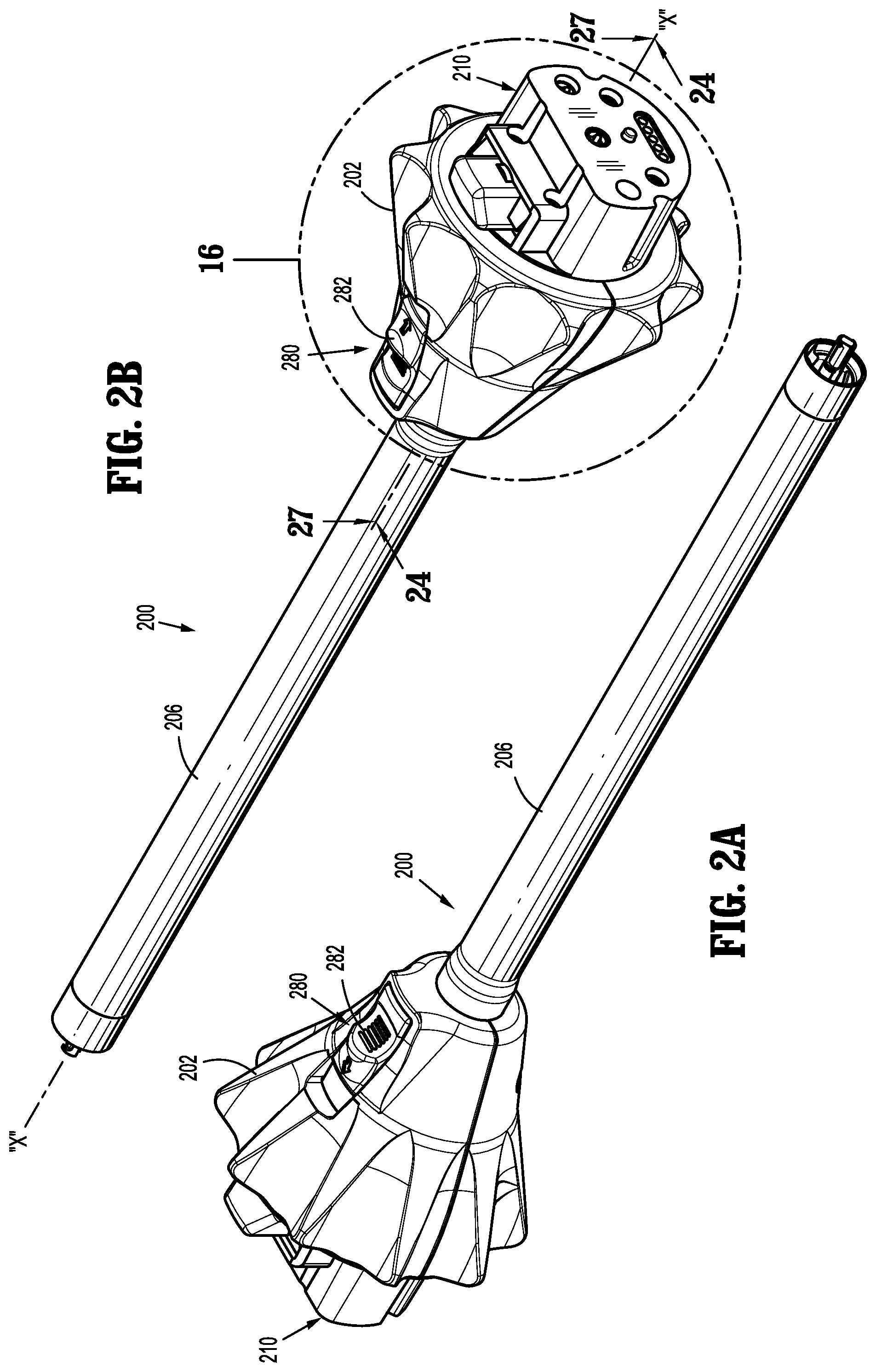
Turning now to FIGS. 1A-47, adapter assembly 200 includes an outer knob housing 202 and an outer tube 206 extending from a distal end of knob housing 202. Knob housing 202 and outer tube 206 are configured and dimensioned to house the components of adapter assembly 200. Outer tube 206 is dimensioned for endoscopic insertion, in particular, that outer tube is passable through a typical trocar port, cannula or the like. Knob housing 202 is dimensioned to not enter the trocar port, cannula of the like. Knob housing 202 is configured and adapted to connect to connecting portion 108 of handle housing 102 of surgical device 100.
Adapter assembly 200 is configured to convert a rotation of either of drive connectors 118 and 120 of surgical device 100 into axial translation useful for operating a drive assembly 360 and an articulation link 366 of loading unit 300, as illustrated in FIG. 48 and as will be described in greater detail below. As illustrated in FIGS. 5, 6, 13, 14, 17, 18, 20, 25-34 and 37-40, adapter assembly 200 includes a proximal inner housing assembly 204 rotatably supporting a first rotatable proximal drive shaft 212, a second rotatable proximal drive shaft 214, and a third rotatable proximal drive shaft 216 therein. Each proximal drive shaft 212, 214, 216 functions as a rotation receiving member to receive rotational forces from respective drive shafts of surgical device 100, as described in greater detail below.
As described briefly above, inner housing assembly 210 of shaft assembly 200 is also configured to rotatably support first, second and third connector sleeves 218, 220 and 222, respectively, arranged in a common plane or line with one another. Each of connector sleeves 218, 220, 222 is configured to mate with respective first, second and third drive connectors 118, 120, 122 of surgical device 100, as described above. Each of connector sleeves 218, 220, 222 is further configured to mate with a proximal end of respective first, second and third proximal drive shafts 212, 214, 216.
Inner housing assembly 210 also includes, as illustrated in FIGS. 6, 17, 27 and 28, a first, a second and a third biasing member 224, 226 and 228 disposed distally of respective first, second and third connector sleeves 218, 220, 222. Each of biasing members 224, 226 and 228 is disposed about respective first, second and third rotatable proximal drive shaft 212, 214 and 216. Biasing members 224, 226 and 228 act on respective connector sleeves 218, 220 and 222 to help maintain connector sleeves 218, 220 and 222 engaged with the distal end of respective drive rotatable drive connectors 118, 120, 122 of surgical device 100 when adapter assembly 200 is connected to surgical device 100.
In particular, first, second and third biasing members 224, 226 and 228 function to bias respective connector sleeves 218, 220 and 222 in a proximal direction. In this manner, during assembly of adapter assembly 200 to surgical device 100, if first, second and or third connector sleeves 218, 220 and/or 222 is/are misaligned with the drive connectors 118, 120, 122 of surgical device 100, first, second and/or third biasing member(s) 224, 226 and/or 228 are compressed. Thus, when surgical device 100 is operated, drive connectors 118, 120, 122 of surgical device 100 will rotate and first, second and/or third biasing member(s) 224, 226 and/or 228 will cause respective first, second and/or third connector sleeve(s) 218, 220 and/or 222 to slide back proximally, effectively coupling drive connectors 118, 120, 122 of surgical device 100 to first, second and/or third proximal drive shaft(s) 212, 214 and 216 of inner housing assembly 210.
Adapter assembly 200 includes a plurality of force/rotation transmitting/converting assemblies, each disposed within inner housing assembly 204 and outer tube 206. Each force/rotation transmitting/converting assembly is configured and adapted to transmit/convert a speed/force of rotation (e.g., increase or decrease) of first, second and third rotatable drive connectors 118, 120 and 122 of surgical instrument 100 before transmission of such rotational speed/force to loading unit 300.
Specifically, as illustrated in FIG. 6, adapter assembly 200 includes a first, a second and a third force/rotation transmitting/converting assembly 240, 250, 260, respectively, disposed within inner housing 208 and outer tube 206. Each force/rotation transmitting/converting assembly 240, 250, 260 is configured and adapted to transmit or convert a rotation of a first, second and third drive connector 118, 120, 122 of surgical device 100 into axial translation of articulation bar 258 of adapter assembly 200, to effectuate articulation of loading unit 300; a rotation of a ring gear 266 of adapter assembly 200, to effectuate rotation of adapter assembly 200; or axial translation of a distal drive member 248 of adapter assembly 200 to effectuate closing, opening and firing of loading unit 300.
As shown in FIGS. 5, 6 and 24-31, first force/rotation transmitting/converting assembly 240 includes first rotatable proximal drive shaft 212, which, as described above, is rotatably supported within inner housing assembly 204. First rotatable proximal drive shaft 212 includes a non-circular or shaped proximal end portion configured for connection with first connector 218 which is connected to respective first connector 118 of surgical device 100. First rotatable proximal drive shaft 212 includes a distal end portion 212b having a threaded outer profile or surface.
First force/rotation transmitting/converting assembly 240 further includes a drive coupling nut 244 rotatably coupled to threaded distal end portion 212b of first rotatable proximal drive shaft 212, and which is slidably disposed within outer tube 206. Drive coupling nut 244 is slidably keyed within proximal core tube portion of outer tube 206 so as to be prevented from rotation as first rotatable proximal drive shaft 212 is rotated. In this manner, as first rotatable proximal drive shaft 212 is rotated, drive coupling nut 244 is translated along threaded distal end portion 212b of first rotatable proximal drive shaft 212 and, in turn, through and/or along outer tube 206.
First force/rotation transmitting/converting assembly 240 further includes a distal drive member 248 that is mechanically engaged with drive coupling nut 244, such that axial movement of drive coupling nut 244 results in a corresponding amount of axial movement of distal drive member 248. The distal end portion of distal drive member 248 supports a connection member 247 configured and dimensioned for selective engagement with a drive member 374 of drive assembly 360 of loading unit 300 (FIG. 47). Drive coupling nut 244 and/or distal drive member 248 function as a force transmitting member to components of loading unit 300, as described in greater detail below.
In operation, as first rotatable proximal drive shaft 212 is rotated, due to a rotation of first connector sleeve 218, as a result of the rotation of the first respective drive connector 118 of surgical device 100, drive coupling nut 244 is caused to be translated axially along first distal drive shaft 242. As drive coupling nut 244 is caused to be translated axially along first distal drive shaft 242, distal drive member 248 is caused to be translated axially relative to outer tube 206. As distal drive member 248 is translated axially, with connection member 247 connected thereto and engaged with drive member 374 of drive assembly 360 of loading unit 300 (FIG. 47), distal drive member 248 causes concomitant axial translation of drive member 374 of loading unit 300 to effectuate a closure of tool assembly 304 and a firing of tool assembly 304 of loading unit 300.
With reference to FIGS. 5-11, 19 and 23-31, second drive converter assembly 250 of adapter assembly 200 includes second proximal drive shaft 214 rotatably supported within inner housing assembly 204. Second rotatable proximal drive shaft 214 includes a non-circular or shaped proximal end portion configured for connection with second connector or coupler 220 which is connected to respective second connector 120 of surgical device 100. Second rotatable proximal drive shaft 214 further includes a distal end portion 214b having a threaded outer profile or surface.
Distal end portion 214b of proximal drive shaft 214 is threadably engaged with an articulation bearing housing 252a of an articulation bearing assembly 252. Articulation bearing assembly 252 includes a housing 252a supporting an articulation bearing 253 having an inner race 253b that is independently rotatable relative to an outer race 253a. Articulation bearing housing 252a has a non-circular outer profile, for example tear-dropped shaped, that is slidably and non-rotatably disposed within a complementary bore 204c (FIGS. 25, 26, 29 and 33) of inner housing hub 204a.
Second drive converter assembly 250 of adapter assembly 200 further includes an articulation bar 258 having a proximal portion 258a secured to inner race 253b of articulation bearing 253. A distal portion 258b of articulation bar 258 includes a slot 258c therein, which is configured to accept a portion 366, e.g., a flag, articulation link (FIG. 47) of loading unit 300. Articulation bar 258 functions as a force transmitting member to components of loading unit 300, as described in greater detail below.
With further regard to articulation bearing assembly 252, articulation bearing assembly 252 is both rotatable and longitudinally translatable. Additionally, it is envisioned that articulation bearing assembly 252 allows for free, unimpeded rotational movement of loading unit 300 when its jaw members 306, 308 are in an approximated position and/or when jaw members 306, 308 are articulated.
In operation, as second proximal drive shaft 214 is rotated due to a rotation of second connector sleeve 220, as a result of the rotation of the second drive connector 120 of surgical device 100, articulation bearing assembly 252 is caused to be translated axially along threaded distal end portion 214b of second proximal drive shaft 214, which in turn causes articulation bar 258 to be axially translated relative to outer tube 206. As articulation bar 258 is translated axially, articulation bar 258, being coupled to articulation link 366 of loading unit 300, causes concomitant axial translation of articulation link 366 of loading unit 300 to effectuate an articulation of tool assembly 304. Articulation bar 258 is secured to inner race 253b of articulation bearing 253 and is thus free to rotate about the longitudinal axis X-X relative to outer race 253a of articulation bearing 253.
As illustrated in FIGS. 6, 17, 18, 20-23, 25-28, 31 and 37-40 and as mentioned above, adapter assembly 200 includes a third force/rotation transmitting/converting assembly 260 supported in inner housing assembly 204. Third force/rotation transmitting/converting assembly 260 includes a rotation ring gear 266 fixedly supported in and connected to outer knob housing 202. Ring gear 266 defines an internal array of gear teeth 266a (FIG. 6). Ring gear 266 includes a pair of diametrically opposed, radially extending protrusions 266b (FIG. 6) projecting from an outer edge thereof. Protrusions 266b are disposed within recesses defined in outer knob housing 202, such that rotation of ring gear 266 results in rotation of outer knob housing 202, and vice a versa.
Third force/rotation transmitting/converting assembly 260 further includes third rotatable proximal drive shaft 216 which, as described above, is rotatably supported within inner housing assembly 204. Third rotatable proximal drive shaft 216 includes a non-circular or shaped proximal end portion configured for connection with third connector 222 which is connected to respective third connector 122 of surgical device 100. Third rotatable proximal drive shaft 216 includes a spur gear 216a keyed to a distal end thereof. A reversing spur gear 264 inter-engages spur gear 216a of third rotatable proximal drive shaft 216 to gear teeth 266a of ring gear 266.
In operation, as third rotatable proximal drive shaft 216 is rotated, due to a rotation of third connector sleeve 222, as a result of the rotation of the third drive connector 122 of surgical device 100, spur gear 216a of third rotatable proximal drive shaft 216 engages reversing gear 264 causing reversing gear 264 to rotate. As reversing gear 264 rotates, ring gear 266 also rotates thereby causing outer knob housing 202 to rotate. As outer knob housing 202 is rotated, outer tube 206 is caused to be rotated about longitudinal axis "X" of adapter assembly 200. As outer tube 206 is rotated, loading unit 300, that is connected to a distal end portion of adapter assembly 200, is also caused to be rotated about a longitudinal axis of adapter assembly 200.
Adapter assembly 200 further includes, as seen in FIGS. 1B, 3-5, 16, 17, 20 and 24-26, an attachment/detachment button 272 supported thereon. Specifically, button 272 is supported on drive coupling assembly 210 of adapter assembly 200 and is biased by a biasing member 274 to an un-actuated condition. Button 272 includes lip or ledge 272a formed therewith that is configured to snap behind a corresponding lip or ledge 108b defined along recess 108a of connecting portion 108 of surgical device 100. In use, when adapter assembly 200 is connected to surgical device 100, lip 272a of button 272 is disposed behind lip 108b of connecting portion 108 of surgical device 100 to secure and retain adapter assembly 200 and surgical device 100 with one another. In order to permit disconnection of adapter assembly 200 and surgical device 100 from one another, button 272 is depresses or actuated, against the bias of biasing member 274, to disengage lip 272a of button 272 and lip 108b of connecting portion 108 of surgical device 100.
With reference to FIGS. 1A, 2A, 2B, 3-5 and 24-26, adapter assembly 200 further includes a lock mechanism 280 for fixing the axial position and radial orientation of distal drive member 248. Lock mechanism 280 includes a button 282 slidably supported on outer knob housing 202. Lock button 282 is connected to an actuation bar 284 that extends longitudinally through outer tube 206. Actuation bar 284 moves upon a movement of lock button 282. Upon a predetermined amount of movement of lock button 282, a distal end of actuation bar 284 may move into contact with a lock out (not shown), which causes the lock out to cam a camming member 288 (FIG. 24) from a recess 249 in distal drive member 248. When camming member 288 is in engagement with recess 249 (e.g., at least partially within recess 249, see FIGS. 6 and 24), the engagement between camming member 288 and distal drive member 248 effectively locks the axial and rotational position of end effector 300 that is engaged with connection member 247.
In operation, in order to lock the position and/or orientation of distal drive member 248, a user moves lock button 282 from a distal position to a proximal position (FIGS. 25 and 26), thereby causing the lock out (not shown) to move proximally such that a distal face of the lock out moves out of contact with camming member 288, which causes camming member 288 to cam into recess 249 of distal drive member 248. In this manner, distal drive member 248 is prevented from distal and/or proximal movement. When lock button 282 is moved from the proximal position to the distal position, the distal end of actuation bar 284 moves distally into the lock out, against the bias of a biasing member (not shown), to force camming member 288 out of recess 249, thereby allowing unimpeded axial translation and radial movement of distal drive member 248.
Reference may be made to U.S. patent application Ser. No. 13/875,571, filed on May 2, 2013, the entire content of which is incorporated herein by reference, for a more detailed discussion of the construction and operation of lock mechanism 280.
With reference to FIGS. 1B, 6, 12-15 and 25-28, adapter assembly 200 includes an electrical assembly 290 supported on and in outer knob housing 202 and inner housing assembly 204. Electrical assembly 290 includes a plurality of electrical contact pins 292, supported on a circuit board 294, for electrical connection to a corresponding electrical plug 190 disposed in connecting portion 108 of surgical device 100. Electrical contacts 290 serve to allow for calibration and communication of life-cycle information to the circuit board of surgical device 100 via electrical plugs 190 that are electrically connected to the circuit board (not shown) of surgical device 100.
Electrical assembly 290 further includes a strain gauge 296 electrically connected to circuit board 294. Strain gauge 296 is provided with a notch 296a which is configured and adapted to receive stem 204d of hub 204a of inner housing assembly 204. Stem 204d of hub 204a functions to restrict rotational movement of strain gauge 296. As illustrated in FIGS. 25-28, first rotatable proximal drive shaft 212 extends through strain gauge 296. Strain gauge 296 provides a closed-loop feedback to a firing/clamping load exhibited by first rotatable proximal drive shaft 212.
Electrical assembly 290 also includes a slip ring 298 disposed core tube of tube 206. Slip ring 298 is in electrical connection with circuit board 294. Slip ring 298 functions to permit rotation of first rotatable proximal drive shaft 212 and axial translation of drive coupling nut 244 while still maintaining electrical contact of electrical contact rings 298a thereof with at least another electrical component within adapter assembly 200, and while permitting the other electrical components to rotate about first rotatable proximal drive shaft 212 and drive coupling nut 244
Electrical assembly 290 may include a slip ring cannula or sleeve 299 positioned core tube of tube 206 to protect and/or shield any wires extending from slip ring 298.
Turning now to FIGS. 6, 11, 14, 32 and 33, inner housing assembly 204 has been designed to reduce incidents of racking of second proximal drive shaft 214 as drive shaft 214 rotates to axially translate articulation bearing assembly 252. Inner housing assembly 204 includes a hub 204a having a distally oriented annular wall 204b defining a substantially circular outer profile, and defining a substantially tear-drop shaped inner recess or bore 204c. Bore 204c of hub 204a is shaped and dimensioned to slidably receive articulation bearing assembly 252 therewithin.
Inner housing assembly 204 includes a ring plate 254a (FIG. 34) secured to a distal face of distally oriented annular wall 204b of hub 204a. Plate 254a defines an aperture 254e therethrough that is sized and formed therein so as to be aligned with second proximal drive shaft 214 and to rotatably receive a distal tip 214c of second proximal drive shaft 214. In this manner, distal tip 214c of second proximal drive shaft 214 is supported and prevented from moving radially away from a longitudinal rotational axis of second proximal drive shaft 214 as second proximal drive shaft 214 is rotated to axially translate articulation bearing assembly 252.
As illustrated in FIGS. 14, 32, 39 and 40, hub 204a defines a feature (e.g., a stem or the like) 204d projecting therefrom which functions to engage notch 296a of strain gauge 296 of electrical assembly 290 to measure forces experienced by shaft 212 as surgical device 100 is operated.
With reference to FIGS. 35-40, a plate bushing 230 of inner housing assembly 204 is shown and described. Plate bushing 230 extends across hub 204a of inner housing assembly 204 and is secured to hub 204a by fastening members. Plate bushing 230 defines three apertures 230a, 230b, 230c that are aligned with and rotatably receive respective first, second and third proximal drive shafts 212, 214, 216 therein. Plate bushing 230 provides a surface against which first, second and third biasing members 224, 226 and 228 come into contact or rest against.
While plate bushing 230 has been shown and described as being a unitary monolithic piece, as illustrated in FIGS. 6 and 37-40, it is envisioned and within the scope of the present application that plate bushing 230 may be separated into several parts including, and not limited to, as seen in FIGS. 40-42, a support plate 230' extending across drive shafts 212, 214, 216, and a separate bushing for each of drive shafts 212, 214, 216 and disposed between the support plate 230' and hub 204a of inner housing assembly 204. Support plate 230' may include a pair of slots 230a', 230b' formed therein, which are configured and adapted to receive tabs 296b of strain gauge 296 that project axially therefrom.
Turning now to FIGS. 43-47, an inner housing assembly 204' according to another embodiment of the present disclosure is shown and will be described. In order to reduce incidents of racking (i.e., distal end 214b of second proximal drive shaft 214 moving radially away from a longitudinal rotational axis thereof) of second proximal drive shaft 214 as drive shaft 214 rotates to axially translate articulation bearing assembly 252, inner housing assembly 204' may include a reinforcement frame or bracket assembly 254'. Bracket assembly 254' includes a first plate 254a' and a second plate 254b' integrally connected to and spaced a distance from first plate 254a' by a plurality of connecting rods 254c' extending therebetween.
First plate 254a' is disposed adjacent to or in close proximity to ring gear 266 and defines an aperture 254d' therethrough. Aperture 254d' is sized and formed in first plate 254a' so as to be aligned with second proximal drive shaft 214 and to permit second proximal drive shaft 214 to freely rotate therewithin. Second plate 254b' is spaced from first plate 254a' so as to be disposed at a distal free end of second proximal drive shaft 214. Second plate 254b' defines an aperture 254e' therethrough. Aperture 254e' is sized and formed in second plate or flange 254b' so as to be aligned with second proximal drive shaft 214 and to rotatably receive a distal tip 214c of second proximal drive shaft 214.
In this manner, distal tip 214c of second proximal drive shaft 214 is supported and prevented from moving radially away from a longitudinal rotational axis of second proximal drive shaft 214 as second proximal drive shaft 214 is rotated to axially translate articulation bearing assembly 252.
As illustrated in FIGS. 38, 46 and 47, inner housing assembly 204' may include a reinforcing sleeve 255' disposed about bracket assembly 254' to further reinforce bracket assembly 254'. It is contemplated in an embodiment that reinforcing sleeve 255' may be interposed between first plate 254a' and second plate 254b' of bracket assembly 254'. It is further contemplated that reinforcing sleeve 255' may be interposed between second plate 254b' and a distally oriented face of proximal inner housing assembly 204'.
In accordance with the present disclosure, an overall length of adapter assembly 200 has been reduced as compared to prior adapter assemblies that have been developed to transmit/convert forces/rotations from surgical device 100 to loading unit 300. By reducing an overall length of adapter assembly 200, a center of gravity of an assembled surgical device 100, adapter assembly 200 and loading unit 300 has been shifted proximally as compared to a center of gravity of an assembled surgical device 100, a prior adapter assembly and a loading unit 300. As such, a level of comfort to the end user in using the electromechanical surgical system of the present disclosure has been increased, and a level of fatigue has been decreased.
In operation, when a button of surgical device 100 is activated by the user, the software checks predefined conditions. If conditions are met, the software controls the motors and delivers mechanical drive to the attached surgical stapler, which can then open, close, rotate, articulate or fire depending on the function of the pressed button. The software also provides feedback to the user by turning colored lights on or off in a defined manner to indicate the status of surgical device 100, adapter assembly 200 and/or loading unit 300.
Reference may be made to U.S. Patent Publication No. 2009/0314821, filed on Aug. 31, 2009, entitled "TOOL ASSEMBLY FOR A SURGICAL STAPLING DEVICE" for a detailed discussion of the construction and operation of loading unit 300, as illustrated in FIGS. 1 and 48.
Any of the components described herein may be fabricated from either metals, plastics, resins, composites or the like taking into consideration strength, durability, wearability, weight, resistance to corrosion, ease of manufacturing, cost of manufacturing, and the like.
It will be understood that various modifications may be made to the embodiments of the presently disclosed adapter assemblies. Therefore, the above description should not be construed as limiting, but merely as exemplifications of embodiments. Those skilled in the art will envision other modifications within the scope and spirit of the present disclosure.
* * * * *
D00000
D00001
D00002
D00003
D00004
D00005
D00006
D00007
D00008
D00009
D00010
D00011
D00012

D00013

D00014

D00015

D00016

D00017

D00018

D00019

D00020

D00021

D00022
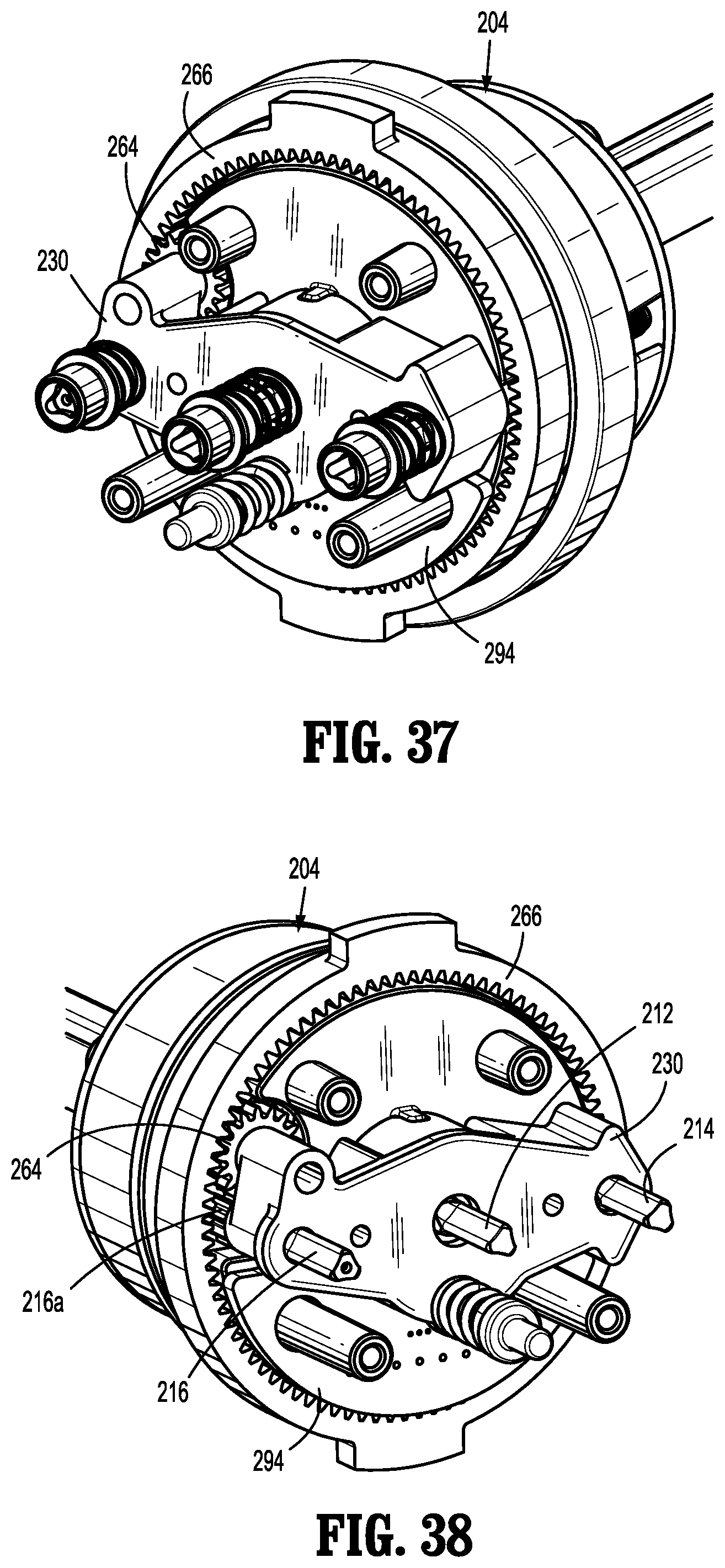
D00023

D00024

D00025

D00026

D00027

XML
uspto.report is an independent third-party trademark research tool that is not affiliated, endorsed, or sponsored by the United States Patent and Trademark Office (USPTO) or any other governmental organization. The information provided by uspto.report is based on publicly available data at the time of writing and is intended for informational purposes only.
While we strive to provide accurate and up-to-date information, we do not guarantee the accuracy, completeness, reliability, or suitability of the information displayed on this site. The use of this site is at your own risk. Any reliance you place on such information is therefore strictly at your own risk.
All official trademark data, including owner information, should be verified by visiting the official USPTO website at www.uspto.gov. This site is not intended to replace professional legal advice and should not be used as a substitute for consulting with a legal professional who is knowledgeable about trademark law.