Surgical adapter assemblies for use between surgical handle assembly and surgical end effectors
Williams , et al. Feb
U.S. patent number 10,561,416 [Application Number 15/606,152] was granted by the patent office on 2020-02-18 for surgical adapter assemblies for use between surgical handle assembly and surgical end effectors. This patent grant is currently assigned to Covidien LP. The grantee listed for this patent is Covidien LP. Invention is credited to John Beardsley, Stanislaw Marczyk, David Racenet, Ryan Williams, Michael Zemlok.


View All Diagrams
| United States Patent | 10,561,416 |
| Williams , et al. | February 18, 2020 |
Surgical adapter assemblies for use between surgical handle assembly and surgical end effectors
Abstract
Adapter assemblies selectively interconnect a surgical end effector that is configured to perform at least a pair of functions and a surgical device that is configured to actuate the end effector. The adapter assembly includes an adapter knob housing configured and adapted for connection with the surgical device and to be in operative communication with each of the at least one rotatable drive shaft of the surgical device. The adapter knob housing defines a lumen extending longitudinally therethrough and a ring gear formed in an inner surface of the lumen of the adapter knob housing. The ring gear defines an internal array of gear teeth which are engaged with a spur gear of a rotatable drive shaft. The adapter knob housing may be a unitary member and may be formed of plastic.
| Inventors: | Williams; Ryan (New Hartford, CT), Marczyk; Stanislaw (Stratford, CT), Racenet; David (Killingworth, CT), Beardsley; John (Wallingford, CT), Zemlok; Michael (Prospect, CT) | ||||||||||
|---|---|---|---|---|---|---|---|---|---|---|---|
| Applicant: |
|
||||||||||
| Assignee: | Covidien LP (Mansfield,
MA) |
||||||||||
| Family ID: | 48746358 | ||||||||||
| Appl. No.: | 15/606,152 | ||||||||||
| Filed: | May 26, 2017 |
Prior Publication Data
| Document Identifier | Publication Date | |
|---|---|---|
| US 20170258467 A1 | Sep 14, 2017 | |
Related U.S. Patent Documents
| Application Number | Filing Date | Patent Number | Issue Date | ||
|---|---|---|---|---|---|
| 14820650 | Aug 7, 2015 | 10251644 | |||
| 13904069 | May 29, 2013 | 10022123 | |||
| 15606152 | |||||
| 15338980 | Oct 31, 2016 | ||||
| 13847791 | Mar 20, 2013 | 9498212 | |||
| 13233299 | Sep 15, 2011 | 8424739 | |||
| 10968525 | Oct 18, 2004 | 8770459 | |||
| 15606152 | |||||
| 14683407 | Apr 10, 2015 | 10041822 | |||
| 12895897 | Oct 1, 2010 | 9113880 | |||
| 12189834 | Aug 12, 2008 | ||||
| 15606152 | |||||
| 15338980 | Oct 31, 2016 | ||||
| 13847791 | Mar 20, 2013 | 9498212 | |||
| 13233299 | Sep 15, 2011 | 8424739 | |||
| 10968525 | Oct 18, 2004 | 8770459 | |||
| 15606152 | |||||
| 14683407 | Apr 10, 2015 | 10041822 | |||
| 12895897 | Oct 1, 2010 | 9113880 | |||
| 61669228 | Jul 9, 2012 | ||||
| 60512481 | Oct 17, 2003 | ||||
| 61248971 | Oct 6, 2009 | ||||
| 61248504 | Oct 5, 2009 | ||||
| 60997854 | Oct 5, 2007 | ||||
| 61669228 | Jul 9, 2012 | ||||
| 60512481 | Oct 17, 2003 | ||||
| Current U.S. Class: | 1/1 |
| Current CPC Class: | A61B 90/00 (20160201); A61B 17/068 (20130101); A61B 17/07207 (20130101); A61B 2017/00473 (20130101); F04C 2270/041 (20130101); A61B 2017/00464 (20130101); A61B 2017/0046 (20130101); A61B 2017/00477 (20130101); A61B 2017/00345 (20130101); A61B 2017/00734 (20130101); A61B 2017/00367 (20130101); A61B 2017/00486 (20130101); A61B 2017/00398 (20130101) |
| Current International Class: | A61B 17/068 (20060101); A61B 17/072 (20060101); A61B 90/00 (20160101); A61B 17/00 (20060101) |
| Field of Search: | ;227/175.1,176.1,178.1,179.1,180.1,19 |
References Cited [Referenced By]
U.S. Patent Documents
| 2777340 | January 1957 | Hettwer et al. |
| 2957353 | October 1960 | Babacz |
| 3111328 | November 1963 | Di Rito et al. |
| 3695058 | October 1972 | Keith, Jr. |
| 3734515 | May 1973 | Dudek |
| 3759336 | September 1973 | Marcovitz et al. |
| 4162399 | July 1979 | Hudson |
| 4606343 | August 1986 | Conta et al. |
| 4705038 | November 1987 | Sjostrom et al. |
| 4722685 | February 1988 | de Estrada et al. |
| 4823807 | April 1989 | Russell et al. |
| 4874181 | October 1989 | Hsu |
| 5129118 | July 1992 | Walmesley |
| 5129570 | July 1992 | Schulze et al. |
| 5152744 | October 1992 | Krause et al. |
| 5301061 | April 1994 | Nakada et al. |
| 5312023 | May 1994 | Green et al. |
| 5326013 | July 1994 | Green et al. |
| 5350355 | September 1994 | Sklar |
| 5383874 | January 1995 | Jackson et al. |
| 5383880 | January 1995 | Hooven |
| 5389098 | February 1995 | Tsuruta et al. |
| 5395033 | March 1995 | Byrne et al. |
| 5400267 | March 1995 | Denen et al. |
| 5405344 | April 1995 | Williamson |
| 5411508 | May 1995 | Bessler et al. |
| 5413267 | May 1995 | Solyntjes et al. |
| 5427087 | June 1995 | Ito et al. |
| 5431323 | July 1995 | Smith |
| 5467911 | November 1995 | Tsuruta et al. |
| 5476379 | December 1995 | Disel |
| 5487499 | January 1996 | Sorrentino et al. |
| 5518163 | May 1996 | Hooven |
| 5518164 | May 1996 | Hooven |
| 5526822 | June 1996 | Burbank et al. |
| 5529235 | June 1996 | Boiarski et al. |
| 5535934 | July 1996 | Boiarski et al. |
| 5535937 | July 1996 | Boiarski et al. |
| 5540375 | July 1996 | Bolanos et al. |
| 5540706 | July 1996 | Aust et al. |
| 5542594 | August 1996 | McKean et al. |
| 5549637 | August 1996 | Crainich |
| 5553675 | September 1996 | Pitzen et al. |
| 5562239 | October 1996 | Boiarski et al. |
| 5564615 | October 1996 | Bishop et al. |
| 5609560 | March 1997 | Ichikawa et al. |
| 5632432 | May 1997 | Schulze et al. |
| 5653374 | August 1997 | Young et al. |
| 5658300 | August 1997 | Bito et al. |
| 5667517 | September 1997 | Hooven |
| 5693042 | December 1997 | Boiarski et al. |
| 5704534 | January 1998 | Huitema et al. |
| 5713505 | February 1998 | Huitema |
| 5762603 | June 1998 | Thompson |
| 5779130 | July 1998 | Alesi et al. |
| 5782396 | July 1998 | Mastri et al. |
| 5782397 | July 1998 | Koukline |
| 5820009 | October 1998 | Melling et al. |
| 5863159 | January 1999 | Lasko |
| 5865361 | February 1999 | Milliman et al. |
| 5871493 | February 1999 | Sjostrom et al. |
| 5908427 | June 1999 | McKean et al. |
| 5954259 | September 1999 | Viola et al. |
| 5964774 | October 1999 | McKean et al. |
| 5993454 | November 1999 | Longo |
| 6010054 | January 2000 | Johnson et al. |
| 6017354 | January 2000 | Culp et al. |
| 6032849 | March 2000 | Mastri et al. |
| 6045560 | April 2000 | McKean et al. |
| 6090123 | July 2000 | Culp et al. |
| 6126651 | October 2000 | Mayer |
| 6129547 | October 2000 | Cise et al. |
| 6165169 | December 2000 | Panescu et al. |
| 6239732 | May 2001 | Cusey |
| 6241139 | June 2001 | Milliman et al. |
| 6264086 | July 2001 | McGuckin, Jr. |
| 6264087 | July 2001 | Whitman |
| 6302311 | October 2001 | Adams et al. |
| 6315184 | November 2001 | Whitman |
| 6321855 | November 2001 | Barnes |
| 6329778 | December 2001 | Culp et al. |
| 6343731 | February 2002 | Adams et al. |
| 6348061 | February 2002 | Whitman |
| 6368324 | April 2002 | Dinger et al. |
| 6371909 | April 2002 | Hoeg et al. |
| 6434507 | August 2002 | Clayton et al. |
| 6443973 | September 2002 | Whitman |
| 6461372 | October 2002 | Jensen et al. |
| 6488197 | December 2002 | Whitman |
| 6491201 | December 2002 | Whitman |
| 6494892 | December 2002 | Ireland et al. |
| 6533157 | March 2003 | Whitman |
| 6537280 | March 2003 | Dinger et al. |
| 6610066 | August 2003 | Dinger et al. |
| 6611793 | August 2003 | Burnside et al. |
| 6645218 | November 2003 | Cassidy et al. |
| 6654999 | December 2003 | Stoddard et al. |
| 6698643 | March 2004 | Whitman |
| 6699177 | March 2004 | Wang et al. |
| 6716233 | April 2004 | Whitman |
| 6743240 | June 2004 | Smith et al. |
| 6783533 | August 2004 | Green et al. |
| 6792390 | September 2004 | Burnside et al. |
| 6793652 | September 2004 | Whitman et al. |
| 6817508 | November 2004 | Racenet et al. |
| 6830174 | December 2004 | Hillstead et al. |
| 6846308 | January 2005 | Whitman et al. |
| 6846309 | January 2005 | Whitman et al. |
| 6849071 | February 2005 | Whitman et al. |
| 6905057 | June 2005 | Swayze et al. |
| 6959852 | November 2005 | Shelton, IV et al. |
| 6964363 | November 2005 | Wales et al. |
| 6981628 | January 2006 | Wales |
| 6981941 | January 2006 | Whitman et al. |
| 6986451 | January 2006 | Mastri et al. |
| 6988649 | January 2006 | Shelton, IV et al. |
| 7032798 | April 2006 | Whitman et al. |
| RE39152 | June 2006 | Aust et al. |
| 7055731 | June 2006 | Shelton, IV et al. |
| 7059508 | June 2006 | Shelton, IV et al. |
| 7077856 | July 2006 | Whitman |
| 7111769 | September 2006 | Wales et al. |
| 7122029 | October 2006 | Koop et al. |
| 7140528 | November 2006 | Shelton, IV |
| 7143923 | December 2006 | Shelton, IV et al. |
| 7143925 | December 2006 | Shelton, IV et al. |
| 7143926 | December 2006 | Shelton, IV et al. |
| 7147138 | December 2006 | Shelton, IV |
| 7172104 | February 2007 | Scirica et al. |
| 7225964 | June 2007 | Mastri et al. |
| 7238021 | July 2007 | Johnson |
| 7246734 | July 2007 | Shelton, IV |
| 7328828 | February 2008 | Ortiz et al. |
| 7364061 | April 2008 | Swayze et al. |
| 7380695 | June 2008 | Doll et al. |
| 7380696 | June 2008 | Shelton, IV et al. |
| 7404508 | July 2008 | Smith et al. |
| 7407078 | August 2008 | Shelton, IV et al. |
| 7416101 | August 2008 | Shelton, IV et al. |
| 7419080 | September 2008 | Smith et al. |
| 7422139 | September 2008 | Shelton, IV et al. |
| 7431189 | October 2008 | Shelton, IV et al. |
| 7441684 | October 2008 | Shelton, IV et al. |
| 7448525 | November 2008 | Shelton, IV et al. |
| 7464846 | December 2008 | Shelton, IV et al. |
| 7464847 | December 2008 | Viola et al. |
| 7464849 | December 2008 | Shelton, IV et al. |
| 7481347 | January 2009 | Roy |
| 7481824 | January 2009 | Boudreaux et al. |
| 7487899 | February 2009 | Shelton, IV et al. |
| 7549564 | June 2009 | Boudreaux |
| 7565993 | July 2009 | Milliman et al. |
| 7568603 | August 2009 | Shelton, IV et al. |
| 7575144 | August 2009 | Ortiz et al. |
| 7588175 | September 2009 | Timm et al. |
| 7588176 | September 2009 | Timm et al. |
| 7637409 | December 2009 | Marczyk |
| 7641093 | January 2010 | Doll et al. |
| 7644848 | January 2010 | Swayze et al. |
| 7670334 | March 2010 | Hueil et al. |
| 7673780 | March 2010 | Shelton, IV et al. |
| 7699835 | April 2010 | Lee et al. |
| 7721931 | May 2010 | Shelton, IV et al. |
| 7738971 | June 2010 | Swayze et al. |
| 7740159 | June 2010 | Shelton, IV et al. |
| 7743960 | June 2010 | Whitman et al. |
| 7758613 | July 2010 | Whitman |
| 7766210 | August 2010 | Shelton, IV et al. |
| 7770773 | August 2010 | Whitman et al. |
| 7770775 | August 2010 | Shelton, IV et al. |
| 7793812 | September 2010 | Moore et al. |
| 7799039 | September 2010 | Shelton, IV et al. |
| 7802712 | September 2010 | Milliman et al. |
| 7803151 | September 2010 | Whitman |
| 7822458 | October 2010 | Webster, III et al. |
| 7845534 | December 2010 | Viola et al. |
| 7845537 | December 2010 | Shelton, IV et al. |
| 7857185 | December 2010 | Swayze et al. |
| 7870989 | January 2011 | Viola et al. |
| 7905897 | March 2011 | Whitman et al. |
| 7918230 | April 2011 | Whitman et al. |
| 7922061 | April 2011 | Shelton, IV et al. |
| 7922719 | April 2011 | Ralph et al. |
| 7947034 | May 2011 | Whitman |
| 7951071 | May 2011 | Whitman et al. |
| 7954682 | June 2011 | Giordano et al. |
| 7959051 | June 2011 | Smith et al. |
| 7963433 | June 2011 | Whitman et al. |
| 7967178 | June 2011 | Scirica et al. |
| 7967179 | June 2011 | Olson et al. |
| 7992758 | August 2011 | Whitman et al. |
| 8016178 | September 2011 | Olson et al. |
| 8016855 | September 2011 | Whitman et al. |
| 8020743 | September 2011 | Shelton, IV |
| 8025199 | September 2011 | Whitman et al. |
| 8035487 | October 2011 | Malackowski |
| 8052024 | November 2011 | Viola et al. |
| 8056787 | November 2011 | Boudreaux et al. |
| 8114118 | February 2012 | Knodel et al. |
| 8132705 | March 2012 | Viola et al. |
| 8152516 | April 2012 | Harvey et al. |
| 8157150 | April 2012 | Viola et al. |
| 8157151 | April 2012 | Ingmanson et al. |
| 8182494 | May 2012 | Yencho et al. |
| 8186555 | May 2012 | Shelton, IV et al. |
| 8186587 | May 2012 | Zmood et al. |
| 8220367 | July 2012 | Hsu |
| 8235273 | August 2012 | Olson et al. |
| 8241322 | August 2012 | Whitman et al. |
| 8272554 | September 2012 | Whitman et al. |
| 8292150 | October 2012 | Bryant |
| 8292888 | October 2012 | Whitman |
| 8303581 | November 2012 | Arts et al. |
| 8342379 | January 2013 | Whitman et al. |
| 8348855 | January 2013 | Hillely et al. |
| 8353440 | January 2013 | Whitman et al. |
| 8357144 | January 2013 | Whitman et al. |
| 8365633 | February 2013 | Simaan et al. |
| 8365972 | February 2013 | Aranyi et al. |
| 8371492 | February 2013 | Aranyi et al. |
| 8372057 | February 2013 | Cude et al. |
| 8391957 | March 2013 | Carlson et al. |
| 8424739 | April 2013 | Racenet et al. |
| 8454585 | June 2013 | Whitman |
| 8505802 | August 2013 | Viola et al. |
| 8517241 | August 2013 | Nicholas et al. |
| 8551076 | October 2013 | Duval et al. |
| 8561871 | October 2013 | Rajappa et al. |
| 8623000 | January 2014 | Humayun et al. |
| 8632463 | January 2014 | Drinan et al. |
| 8647258 | February 2014 | Aranyi et al. |
| 8657174 | February 2014 | Yates et al. |
| 8657177 | February 2014 | Scirica et al. |
| 8672206 | March 2014 | Aranyi et al. |
| 8696552 | April 2014 | Whitman |
| 8708213 | April 2014 | Shelton, IV et al. |
| 8752749 | June 2014 | Moore et al. |
| 8758391 | June 2014 | Swayze et al. |
| 8806973 | August 2014 | Ross et al. |
| 8851355 | October 2014 | Aranyi et al. |
| 8858571 | October 2014 | Shelton, IV et al. |
| 8875972 | November 2014 | Weisenburgh, II et al. |
| 8893946 | November 2014 | Boudreaux et al. |
| 8899462 | December 2014 | Kostrzewski et al. |
| 8939344 | January 2015 | Olson et al. |
| 8960519 | February 2015 | Whitman et al. |
| 8961396 | February 2015 | Azarbarzin et al. |
| 8967443 | March 2015 | McCuen |
| 8968276 | March 2015 | Zemlok et al. |
| 8968337 | March 2015 | Whitfield et al. |
| 8992422 | March 2015 | Spivey et al. |
| 9064653 | June 2015 | Prest et al. |
| 9113875 | August 2015 | Viola et al. |
| 9216013 | December 2015 | Scirica et al. |
| 9282961 | March 2016 | Whitman et al. |
| 9282963 | March 2016 | Bryant |
| 9295522 | March 2016 | Kostrzewski |
| 9307986 | April 2016 | Hall et al. |
| 10022123 | July 2018 | Williams |
| 10251644 | April 2019 | Williams |
| 2002/0049454 | April 2002 | Whitman et al. |
| 2002/0165541 | November 2002 | Whitman |
| 2003/0038938 | February 2003 | Jung et al. |
| 2003/0165794 | September 2003 | Matoba |
| 2004/0111012 | June 2004 | Whitman |
| 2004/0133189 | July 2004 | Sakurai |
| 2004/0176751 | September 2004 | Weitzner et al. |
| 2005/0131442 | June 2005 | Yachia et al. |
| 2006/0142656 | June 2006 | Malackowski et al. |
| 2006/0142740 | June 2006 | Sherman et al. |
| 2006/0278680 | December 2006 | Viola et al. |
| 2007/0023476 | February 2007 | Whitman et al. |
| 2007/0023477 | February 2007 | Whitman et al. |
| 2007/0029363 | February 2007 | Popov |
| 2007/0055219 | March 2007 | Whitman et al. |
| 2007/0084897 | April 2007 | Shelton et al. |
| 2007/0102472 | May 2007 | Shelton |
| 2007/0152014 | July 2007 | Gillum et al. |
| 2007/0175949 | August 2007 | Shelton et al. |
| 2007/0175950 | August 2007 | Shelton et al. |
| 2007/0175951 | August 2007 | Shelton et al. |
| 2007/0175955 | August 2007 | Shelton et al. |
| 2007/0175961 | August 2007 | Shelton et al. |
| 2008/0029570 | February 2008 | Shelton et al. |
| 2008/0029573 | February 2008 | Shelton et al. |
| 2008/0029574 | February 2008 | Shelton et al. |
| 2008/0029575 | February 2008 | Shelton et al. |
| 2008/0058801 | March 2008 | Taylor et al. |
| 2008/0109012 | May 2008 | Falco et al. |
| 2008/0110958 | May 2008 | McKenna et al. |
| 2008/0167736 | July 2008 | Swayze et al. |
| 2008/0185419 | August 2008 | Smith et al. |
| 2008/0188841 | August 2008 | Tomasello et al. |
| 2008/0197167 | August 2008 | Viola et al. |
| 2008/0208195 | August 2008 | Shores et al. |
| 2008/0234715 | September 2008 | Pesce et al. |
| 2008/0237296 | October 2008 | Boudreaux et al. |
| 2008/0251561 | October 2008 | Eades et al. |
| 2008/0255413 | October 2008 | Zemlok et al. |
| 2008/0255607 | October 2008 | Zemlok |
| 2008/0262654 | October 2008 | Omori et al. |
| 2008/0308603 | December 2008 | Shelton et al. |
| 2009/0090763 | April 2009 | Zemlok et al. |
| 2009/0099876 | April 2009 | Whitman |
| 2009/0138006 | May 2009 | Bales et al. |
| 2009/0171147 | July 2009 | Lee et al. |
| 2009/0182193 | July 2009 | Whitman et al. |
| 2009/0209990 | August 2009 | Yates et al. |
| 2009/0254094 | October 2009 | Knapp et al. |
| 2010/0069942 | March 2010 | Shelton, IV |
| 2010/0193568 | August 2010 | Scheib et al. |
| 2010/0211053 | August 2010 | Ross et al. |
| 2010/0225073 | September 2010 | Porter et al. |
| 2011/0006101 | January 2011 | Hall et al. |
| 2011/0017801 | January 2011 | Zemlok et al. |
| 2011/0071508 | March 2011 | Duval et al. |
| 2011/0077673 | March 2011 | Grubac et al. |
| 2011/0082387 | April 2011 | Miller et al. |
| 2011/0121049 | May 2011 | Malinouskas et al. |
| 2011/0125138 | May 2011 | Malinouskas et al. |
| 2011/0139851 | June 2011 | McCuen |
| 2011/0155783 | June 2011 | Rajappa et al. |
| 2011/0155786 | June 2011 | Shelton, IV |
| 2011/0172648 | July 2011 | Jeong |
| 2011/0174099 | July 2011 | Ross et al. |
| 2011/0204119 | August 2011 | McCuen |
| 2011/0218522 | September 2011 | Whitman |
| 2011/0253765 | October 2011 | Nicholas et al. |
| 2011/0276057 | November 2011 | Conlon et al. |
| 2011/0290854 | December 2011 | Timm et al. |
| 2011/0295242 | December 2011 | Spivey et al. |
| 2011/0295269 | December 2011 | Swensgard et al. |
| 2012/0000962 | January 2012 | Racenet et al. |
| 2012/0074199 | March 2012 | Olson et al. |
| 2012/0089131 | April 2012 | Zemlok et al. |
| 2012/0104071 | May 2012 | Bryant |
| 2012/0116368 | May 2012 | Viola |
| 2012/0143002 | June 2012 | Aranyi et al. |
| 2012/0172924 | July 2012 | Allen, IV |
| 2012/0223121 | September 2012 | Viola et al. |
| 2012/0245428 | September 2012 | Smith et al. |
| 2012/0253329 | October 2012 | Zemlok et al. |
| 2012/0310220 | December 2012 | Malkowski et al. |
| 2012/0323226 | December 2012 | Chowaniec et al. |
| 2012/0330285 | December 2012 | Hartoumbekis et al. |
| 2013/0018361 | January 2013 | Bryant |
| 2013/0093149 | April 2013 | Saur et al. |
| 2013/0098966 | April 2013 | Kostrzewski et al. |
| 2013/0098968 | April 2013 | Aranyi et al. |
| 2013/0098969 | April 2013 | Scirica et al. |
| 2013/0181035 | July 2013 | Milliman |
| 2013/0184704 | July 2013 | Beardsley et al. |
| 2013/0214025 | August 2013 | Zemlok et al. |
| 2013/0240596 | September 2013 | Whitman |
| 2013/0274722 | October 2013 | Kostrzewski et al. |
| 2013/0282052 | October 2013 | Aranyi et al. |
| 2013/0292451 | November 2013 | Viola et al. |
| 2013/0313304 | November 2013 | Shelton, IV et al. |
| 2013/0317486 | November 2013 | Nicholas et al. |
| 2013/0319706 | December 2013 | Nicholas et al. |
| 2013/0324978 | December 2013 | Nicholas et al. |
| 2013/0324979 | December 2013 | Nicholas et al. |
| 2013/0334281 | December 2013 | Williams |
| 2014/0012236 | January 2014 | Williams et al. |
| 2014/0012237 | January 2014 | Pribanic et al. |
| 2014/0012289 | January 2014 | Snow et al. |
| 2014/0025046 | January 2014 | Williams et al. |
| 2014/0110455 | April 2014 | Ingmanson et al. |
| 2014/0207125 | July 2014 | Applegate et al. |
| 2014/0207182 | July 2014 | Zergiebel et al. |
| 2014/0236173 | August 2014 | Scirica et al. |
| 2014/0236174 | August 2014 | Williams et al. |
| 2014/0276932 | September 2014 | Williams et al. |
| 2014/0299647 | October 2014 | Scirica et al. |
| 2014/0303668 | October 2014 | Nicholas et al. |
| 2014/0358129 | December 2014 | Zergiebel et al. |
| 2014/0361068 | December 2014 | Aranyi et al. |
| 2014/0373652 | December 2014 | Zergiebel et al. |
| 2015/0048144 | February 2015 | Whitman |
| 2015/0076205 | March 2015 | Zergiebel |
| 2015/0080912 | March 2015 | Sapre |
| 2015/0157321 | June 2015 | Zergiebel et al. |
| 2015/0164502 | June 2015 | Richard et al. |
| 2015/0272577 | October 2015 | Zemlok et al. |
| 2015/0297199 | October 2015 | Nicholas et al. |
| 2015/0303996 | October 2015 | Calderoni |
| 2015/0320420 | November 2015 | Penna et al. |
| 2015/0327850 | November 2015 | Kostrzewski |
| 2015/0342601 | December 2015 | Williams et al. |
| 2015/0342603 | December 2015 | Zergiebel et al. |
| 2015/0374366 | December 2015 | Zergiebel et al. |
| 2015/0374370 | December 2015 | Zergiebel et al. |
| 2015/0374371 | December 2015 | Richard et al. |
| 2015/0374372 | December 2015 | Zergiebel et al. |
| 2015/0374449 | December 2015 | Chowaniec et al. |
| 2015/0380187 | December 2015 | Zergiebel et al. |
| 2016/0095585 | April 2016 | Zergiebel et al. |
| 2016/0095596 | April 2016 | Scirica et al. |
| 2016/0106406 | April 2016 | Cabrera et al. |
| 2016/0113648 | April 2016 | Zergiebel et al. |
| 2016/0113649 | April 2016 | Zergiebel et al. |
| 2008229795 | Apr 2009 | AU | |||
| 2451558 | Jan 2003 | CA | |||
| 101283924 | Oct 2008 | CN | |||
| 101856251 | Oct 2010 | CN | |||
| 102113902 | Jul 2011 | CN | |||
| 102247182 | Nov 2011 | CN | |||
| 102008053842 | May 2010 | DE | |||
| 0634144 | Jan 1995 | EP | |||
| 0648476 | Apr 1995 | EP | |||
| 0686374 | Dec 1995 | EP | |||
| 0705571 | Apr 1996 | EP | |||
| 1690502 | Aug 2006 | EP | |||
| 1723913 | Nov 2006 | EP | |||
| 1736112 | Dec 2006 | EP | |||
| 1759652 | Mar 2007 | EP | |||
| 1769754 | Apr 2007 | EP | |||
| 1772105 | Apr 2007 | EP | |||
| 1774914 | Apr 2007 | EP | |||
| 1 813 203 | Aug 2007 | EP | |||
| 1813199 | Aug 2007 | EP | |||
| 1813211 | Aug 2007 | EP | |||
| 1908412 | Apr 2008 | EP | |||
| 1917929 | May 2008 | EP | |||
| 1943954 | Jul 2008 | EP | |||
| 1943956 | Jul 2008 | EP | |||
| 1943958 | Jul 2008 | EP | |||
| 1943976 | Jul 2008 | EP | |||
| 1952769 | Aug 2008 | EP | |||
| 2005898 | Dec 2008 | EP | |||
| 2027819 | Feb 2009 | EP | |||
| 2044890 | Apr 2009 | EP | |||
| 2055243 | May 2009 | EP | |||
| 2090247 | Aug 2009 | EP | |||
| 2090251 | Aug 2009 | EP | |||
| 2098170 | Sep 2009 | EP | |||
| 2100561 | Sep 2009 | EP | |||
| 2100562 | Sep 2009 | EP | |||
| 2165664 | Mar 2010 | EP | |||
| 2236098 | Oct 2010 | EP | |||
| 2245994 | Nov 2010 | EP | |||
| 2263568 | Dec 2010 | EP | |||
| 2272443 | Jan 2011 | EP | |||
| 2316345 | May 2011 | EP | |||
| 2324776 | May 2011 | EP | |||
| 2329773 | Jun 2011 | EP | |||
| 2333509 | Jun 2011 | EP | |||
| 2377472 | Oct 2011 | EP | |||
| 2462878 | Jun 2012 | EP | |||
| 2462880 | Jun 2012 | EP | |||
| 2491872 | Aug 2012 | EP | |||
| 2586382 | May 2013 | EP | |||
| 2606834 | Jun 2013 | EP | |||
| 2668910 | Dec 2013 | EP | |||
| 2676615 | Dec 2013 | EP | |||
| 2815705 | Dec 2014 | EP | |||
| 2333509 | Feb 2010 | ES | |||
| 2861574 | May 2005 | FR | |||
| 08-038488 | Feb 1996 | JP | |||
| 2005-125075 | May 2005 | JP | |||
| 2007-508868 | Apr 2007 | JP | |||
| 2009-233333 | Oct 2009 | JP | |||
| 2011-115594 | Jun 2011 | JP | |||
| 20120022521 | Mar 2012 | KR | |||
| 91/12773 | Sep 1991 | WO | |||
| 99/15086 | Apr 1999 | WO | |||
| 2000/072760 | Dec 2000 | WO | |||
| 2000/072765 | Dec 2000 | WO | |||
| 2003/000138 | Jan 2003 | WO | |||
| 2003/026511 | Apr 2003 | WO | |||
| 2003/030743 | Apr 2003 | WO | |||
| 2003065916 | Aug 2003 | WO | |||
| 2003/077769 | Sep 2003 | WO | |||
| 2003090630 | Nov 2003 | WO | |||
| 2004/107989 | Dec 2004 | WO | |||
| 2006/042210 | Apr 2006 | WO | |||
| 2007016290 | Feb 2007 | WO | |||
| 2007/026354 | Mar 2007 | WO | |||
| 2007137304 | Nov 2007 | WO | |||
| 2008/131362 | Oct 2008 | WO | |||
| 2008/133956 | Nov 2008 | WO | |||
| 2009039506 | Mar 2009 | WO | |||
| 2007014355 | Apr 2009 | WO | |||
| 2009/132359 | Oct 2009 | WO | |||
| 2009/143092 | Nov 2009 | WO | |||
| 2009149234 | Dec 2009 | WO | |||
| 2011/108840 | Sep 2011 | WO | |||
| 2012/040984 | Apr 2012 | WO | |||
Other References
|
Chinese Office Action dated Oct. 23, 2017 issued in corresponding Chinese Application No. 2013102866767. cited by applicant . International Search Report corresponding to PCT/US2005/027266, completed May 30, 2008 and dated Jun. 18, 2008; (2 pp.). cited by applicant . Extended European Search Report corresponding to EP 08 25 2703.7, completed Oct. 23, 2008 and dated Oct. 31, 2008; (7 pp.). cited by applicant . Extended European Search Report corresponding to EP 08 25 3184.9, completed Feb. 12, 2009 and dated Feb. 27, 2009; (3 pp.). cited by applicant . Extended European Search Report corresponding to EP 10 25 0228.3, completed May 20, 2010 and dated Jun. 1, 2010; (6 pp.). cited by applicant . Extended European Search Report corresponding to EP 10 25 2037.6, completed Mar. 1, 2011 and dated Mar. 9, 2011; (3 pp.). cited by applicant . Extended European Search Report corresponding to EP 10 25 1968.3, completed on Jul. 4, 2011 and dated Jul. 14, 2011; (12 pp.). cited by applicant . Extended European Search Report corresponding to EP 11 15 2266.0, completed Jul. 15, 2011 and dated Jul. 28, 2011; (3 pp.). cited by applicant . Extended European Search Report corresponding to EP 11 25 0462.6, completed Jul. 20, 2011 and dated Jul. 28, 2011; (6 pp.). cited by applicant . Extended European Search Report corresponding to EP 11 25 0771.0, completed Feb. 7, 2012 and dated Feb. 17, 2012; (3 pp.). cited by applicant . Extended European Search Report corresponding to EP 06 78 8914.7, completed May 3, 2012 and dated May 11, 2012; (8 pp.). cited by applicant . Partial European Search Report corresponding to EP 12 18 6177.7, completed Jan. 30, 2013 and dated Feb. 12, 2013; (6 pp.). cited by applicant . Extended European Search Report corresponding to EP No. 11 17 8021.9, dated Jun. 4, 2013; (3 pp). cited by applicant . Extended European Search Report corresponding to EP No. 13 16 3033.7, completed Jun. 27, 2013 and dated Jul. 15, 2013; (8 pp). cited by applicant . Extended European Search Report corresponding to EP No. 12 18 6177.7, completed Aug. 14, 2013 and dated Aug. 23, 2013; (8 pp). cited by applicant . Partial European Search Report corresponding to EP No. 13 17 1742.3, completed Sep. 17, 2013 and dated Sep. 25, 2013; (8 pp). cited by applicant . Partial European Search Report corresponding to EP No. 13 17 2400.7, completed Sep. 18, 2013 and dated Oct. 1, 2013; (7 pp). cited by applicant . Extended European Search Report corresponding to EP No. 13 17 5475.6, completed Sep. 23, 2013 and dated Oct. 1, 2013; (8 pp). cited by applicant . Extended European Search Report corresponding to EP No. 13 17 5478.0, completed Sep. 24, 2013 and dated Oct. 2, 2013; (6 pp). cited by applicant . Extended European Search Report corresponding to EP No. 13 17 5479.8, completed Sep. 27, 2013 and dated Oct. 10, 2013; (7 pp). cited by applicant . Partial Extended European Search Report corresponding to EP 13 17 5477.2, completed Oct. 7, 2013 and dated Oct. 15, 2013; (7 pp). cited by applicant . Extended European Search Report corresponding to EP No. 08 25 2703.7, completed Oct. 23, 2008 and dated Oct. 31, 2008; (7 pp). cited by applicant . European search Report from Appl. No. 13177163.6 dated Nov. 15, 2013. (8 pp). cited by applicant . Extended European Search Report from EP Application No. 13172400.7 dated Jan. 21, 2014. cited by applicant . Extended European Search Report from EP Application No. 13189026.1 dated Jan. 31, 2014. cited by applicant . The extended European Search Report from Application No. EP 13177163.6 dated Feb. 6, 2014. cited by applicant . Extended European Search Report from Application No. EP 13175477.2 dated Feb. 6, 2014. cited by applicant . Extended European Search Report from Application No. EP 13169998.5 dated Feb. 24, 2014. cited by applicant . Extended European Search Report corresponding to EP 13176805.3, dated Nov. 4, 2013. cited by applicant . Extended European Search Report from Application No. EP 13171742.3 dated Jan. 3, 2014. cited by applicant . Extended European Search Report, dated May 27, 2015, corresponding to European Patent Application No. 15152791.8; 5 pages. cited by applicant . Extended European Search Report corresponding to International Application No. EP 15 15 1076.5 dated Apr. 22, 2015. cited by applicant . Japanese Office Action corresponding to International Application No. JP 2011-084092 dated Jan. 14, 2016. cited by applicant . Extended European Search Report corresponding to International Application No. EP 12 19 7970.2 dated Jan. 28, 2016. cited by applicant . Chinese Office Action corresponding to International Application No. CN 201210560638.1 dated Oct. 21, 2015. cited by applicant . European Office Action corresponding to International Application No. EP 14 15 9056.2 dated Oct. 26, 2015. cited by applicant . Australian Examination Report No. 1 corresponding to International Application No. AU 2015200153 dated Dec. 11, 2015. cited by applicant . Australian Examination Report No. 1 corresponding to International Application No. AU 2014204542 dated Jan. 7, 2016. cited by applicant . Office Action corresponding to International Application No. CN 201310125449.6 dated Feb. 3, 2016. cited by applicant . Extended European Search Report corresponding to International Application No. EP 15 19 0245.9 dated Jan. 28, 2016. cited by applicant . Extended European Search Report corresponding to International Application No. EP 15 16 7793.7 dated Apr. 5, 2016. cited by applicant . European Office Action corresponding to International Application No. EP 14 18 4882.0 dated Apr. 25, 2016. cited by applicant . Extended European Search Report corresponding to International Application No. EP 14 19 6704.2 dated Sep. 24, 2015. cited by applicant . International Search Report and Written Opinion corresponding to Int'l Appln. No. PCT/US2015/051837, dated Dec. 21, 2015. cited by applicant . Extended European Search Report corresponding to International Application No. EP 14 19 7563.1 dated Aug. 5, 2015. cited by applicant . Partial European Search Report corresponding to International Application No. EP 15 19 0643.5 dated Feb. 26, 2016. cited by applicant . Extended European Search Report corresponding to International Application No. EP 15 16 6899.3 dated Feb. 3, 2016. cited by applicant . Extended European Search Report corresponding to International Application No. EP 14 19 9783.3 dated Dec. 22, 2015. cited by applicant . Extended European Search Report corresponding to International Application No. EP 15 17 3807.7 dated Nov. 24, 2015. cited by applicant . Extended European Search Report corresponding to International Application No. EP 15 19 0760.7 dated Apr. 1, 2016. cited by applicant . Extended European Search Report corresponding to International Application No. EP 15 17 3803.6 dated Nov. 24, 2015. cited by applicant . Extended European Search Report corresponding to International Application No. EP 15 17 3804.4 dated Nov. 24, 2015. cited by applicant . Extended European Search Report corresponding to International Application No. EP 15 18 8539.9 dated Feb. 17, 2016. cited by applicant . Extended European Search Report corresponding to International Application No. EP 15 17 3910.9 dated Nov. 13, 2015. cited by applicant . European Office Action corresponding to International Application No. EP 14 15 2236.7 dated Aug. 11, 2015. cited by applicant . Extended European Search Report corresponding to International Application No. EP 15 18 4915.5 dated Jan. 5, 2016. cited by applicant . Chinese Office Action (with English translation), dated Jul. 1, 2016, corresponding to Chinese Application No. 201310286676.7; 20 total pages. cited by applicant . Chinese Office Action (with English translation), dated May 27, 2017, corresponding to Chinese Application No. 201310286676.7; 21 total pages. cited by applicant . Japanese Office Action (with English translation), dated Apr. 17, 2017, corresponding to Japanese Application No. 2013-142552; 6 total pages. cited by applicant . Extended European Search Report corresponding to European Application No. EP 17 15 3830.9, dated Jul. 20, 2017; 10 pages. cited by applicant . Japanese Notice of Allowance with English Summary Form, corresponding to Japanese Application No. 2013-142552, dated Aug. 1, 2017; 4 total pages. cited by applicant. |
Primary Examiner: Chukwurah; Nathaniel C
Parent Case Text
CROSS REFERENCE TO RELATED APPLICATION
The present application is a Continuation Application of U.S. patent application Ser. No. 14/820,650, filed on Aug. 7, 2015 (now U.S. Pat. No. 10,251,644), which is a Continuation Application of U.S. patent application Ser. No. 13/904,069, filed on May 29, 2013 (now U.S. Pat. No. 10,022,123), which claims the benefit of and priority to U.S. Provisional Application Ser. No. 61/669,228, filed on Jul. 9, 2012, the entire content of each of which is incorporated by reference herein.
The present application is also a Continuation-in-Part Application of U.S. patent application Ser. No. 15/338,980, filed on Oct. 31, 2016, which is a Continuation Application of U.S. patent application Ser. No. 13/847,791, filed on Mar. 20, 2013 (now U.S. Pat. No. 9,498,212), which is a Continuation Application of U.S. patent application Ser. No. 13/233,299, filed on Sep. 15, 2011 (now U.S. Pat. No. 8,424,739), which is a Continuation Application of U.S. patent application Ser. No. 10/968,525, filed on Oct. 18, 2004 (now U.S. Pat. No. 8,770,459), which claims the benefit of and priority to U.S. Provisional Application Ser. No. 60/512,481 filed Oct. 17, 2003, the entire content of each of which is incorporated by reference herein.
The present application is also a Continuation-in-Part Application of U.S. patent application Ser. No. 14/683,407, filed on Apr. 10, 2015 (now U.S. Pat. No. 10,041,822), which is a Continuation-in-Part of U.S. patent application Ser. No. 12/895,897, filed on Oct. 1, 2010 (now U.S. Pat. No. 9,113,880), which claims the benefit of and priority to U.S. Provisional Application Ser. No. 61/248,971, filed on Oct. 6, 2009 and U.S. Provisional Application Ser. No. 61/248,504, filed on Oct. 5, 2009, the entire content of each of which is incorporated by reference herein.
U.S. patent application Ser. No. 12/895,897, filed on Oct. 1, 2010 (now U.S. Pat. No. 9,113,880) is also a Continuation-in-Part Application of U.S. Patent Application Ser. No. 12/189,834, filed on Aug. 12, 2008 (now abandoned), which claims the benefit and priority to U.S. Provisional Application Ser. No. 60,997,854, filed on Oct. 5, 2007, the entire content of each of which is incorporated by reference herein.
Claims
What is claimed is:
1. An adapter assembly for selectively interconnecting a surgical end effector and a surgical device, the adapter assembly comprising: an adapter knob housing configured to couple to the surgical device, the adapter knob housing including: an inner surface defining a lumen extending longitudinally through the adapter knob housing; and a ring gear formed in the inner surface of the adapter knob housing; an outer tube having a proximal end portion supported by the adapter knob housing and a distal end portion configured to couple to the end effector; and a proximal drive shaft defining a longitudinal axis and rotatably supported in the adapter knob housing, the proximal drive shaft having a gear operably coupled to the ring gear, wherein when the adapter assembly is connected to the surgical device and the end effector a rotation of the proximal drive shaft about the longitudinal axis rotates the adapter knob housing and the end effector.
2. The adapter assembly according to claim 1, wherein the ring gear defines an internal annular array of gear teeth.
3. The adapter assembly according to claim 2, wherein the internal annular array of gear teeth project into the lumen.
4. The adapter assembly according to claim 1, wherein the adapter knob housing is formed as a unitary molded component.
5. The adapter assembly according to claim 4, wherein the adapter knob housing is formed from a thermoplastic polymer.
6. An adapter assembly for selectively interconnecting an end effector and a surgical device, the adapter assembly comprising: an adapter knob housing configured to couple to the surgical device and including: an inner surface defining a lumen extending longitudinally through the adapter knob housing; and a ring gear monolithically formed in the inner surface of the adapter knob housing.
7. The adapter assembly according to claim 6, wherein the ring gear defines an internal annular array of gear teeth.
8. The adapter assembly according to claim 7, wherein the internal annular array of gear teeth project into the lumen.
9. The adapter assembly according to claim 6, wherein the adapter knob housing is formed as a unitary molded component.
10. The adapter assembly according to claim 6, wherein the adapter knob housing is formed from a thermoplastic polymer.
11. The adapter assembly according to claim 6, further comprising a proximal drive shaft defining a longitudinal axis and rotatably supported in the adapter knob housing.
12. The adapter assembly according to claim 11, wherein the proximal drive shaft includes a gear operably coupled to the ring gear of the adapter knob housing such that rotation of the proximal drive shaft about the longitudinal axis rotates the adapter knob housing.
Description
BACKGROUND
1. Technical Field
The present disclosure relates to surgical devices. More specifically, the present disclosure relates to surgical adapters and/or adapter assemblies for use between and for interconnecting a powered, rotating and/or articulating surgical device or handle assembly and an end effector for clamping, cutting and/or stapling tissue.
2. Background of Related Art
One type of surgical device is a linear clamping, cutting and stapling device. Such a device may be employed in a surgical procedure to resect a cancerous or anomalous tissue from a gastro-intestinal tract. Conventional linear clamping, cutting and stapling instruments include a pistol grip-styled structure having an elongated shaft and distal portion. The distal portion includes a pair of scissors-styled gripping elements, which clamp the open ends of the colon closed. In this device, one of the two scissors-styled gripping elements, such as the anvil portion, moves or pivots relative to the overall structure, whereas the other gripping element remains fixed relative to the overall structure. The actuation of this scissoring device (the pivoting of the anvil portion) is controlled by a grip trigger maintained in the handle.
In addition to the scissoring device, the distal portion also includes a stapling mechanism. The fixed gripping element of the scissoring mechanism includes a staple cartridge receiving region and a mechanism for driving the staples up through the clamped end of the tissue against the anvil portion, thereby sealing the previously opened end. The scissoring elements may be integrally formed with the shaft or may be detachable such that various scissoring and stapling elements may be interchangeable.
A number of surgical device manufacturers have developed product lines with proprietary powered drive systems for operating and/or manipulating the surgical device. In many instances the surgical devices include a powered handle assembly, which is reusable, and a disposable end effector or the like that is selectively connected to the powered handle assembly prior to use and then disconnected from the end effector following use in order to be disposed of or in some instances sterilized for re-use.
Many of the existing end effectors for use with many of the existing powered surgical devices and/or handle assemblies are driven by a linear force. For examples, end effectors for performing endo-gastrointestinal anastomosis procedures, end-to-end anastomosis procedures and transverse anastomosis procedures, each typically require a linear driving force in order to be operated. As such, these end effectors are not compatible with surgical devices and/or handle assemblies that use a rotary motion to deliver power or the like.
In order to make the linear driven end effectors compatible with powered surgical devices and/or handle assemblies that use a rotary motion to deliver power, a need exists for adapters and/or adapter assemblies to interface between and interconnect the linear driven end effectors with the powered rotary driven surgical devices and/or handle assemblies.
Many of these powered rotary driven surgical devices and/or handle assemblies are complex devices, including many parts and requiring extensive labor to assemble. Accordingly, a need exists to develop powered rotary driven surgical devices and/or handle assemblies that incorporate fewer parts, are less labor intensive to assemble and ultimately more economical to manufacture.
SUMMARY
The present disclosure relates to surgical adapters and/or adapter assemblies for use between and for interconnecting a powered, rotating and/or articulating surgical device or handle assembly and an end effector for clamping, cutting and/or stapling tissue.
According to an aspect of the present disclosure, an adapter assembly is provided for selectively interconnecting a surgical end effector that is configured to perform a function and a surgical device that is configured to actuate the end effector, the end effector including at least one axially translatable drive member, and the surgical device including at least one rotatable drive shaft. The adapter assembly includes an adapter knob housing configured and adapted for connection with the surgical device and to be in operative communication with each of the at least one rotatable drive shaft of the surgical device. The adapter knob housing defines a lumen extending longitudinally therethrough. The adapter assembly includes an outer tube having a proximal end supported by the adapter knob housing and a distal end configured and adapted for connection with the end effector, wherein the distal end of the outer tube is in operative communication with each of the at least one axially translatable drive member of the end effector. The adapter assembly includes a drive transmitting assembly having a proximal rotatable drive shaft rotatably supported in the adapter knob housing and having a spur gear supported on a distal end thereof and a proximal end connectable to a rotatable drive shaft of the surgical device; and a ring gear formed in an inner surface of the lumen of the adapter knob housing, the ring gear defining an internal array of gear teeth which are engaged with the spur gear of the proximal rotatable drive shaft. In use, rotation of the rotatable drive shaft of the surgical device results in rotation of the proximal drive shaft, and wherein rotation of the proximal drive shaft results in rotation of adapter knob housing via the ring gear, and rotation of the distal coupling assembly to rotate the end effector.
According to another aspect of the present disclosure, an electromechanical surgical system is provided and includes a hand-held surgical device, an end effector, and an adapter assembly for selectively interconnecting the end effector and the surgical device.
The hand-held surgical device includes a device housing defining a connecting portion for selectively connecting with an adapter assembly.
The end effector includes at least one axially translatable drive member.
The adapter assembly includes an adapter knob housing configured and adapted for connection with the surgical device and to be in operative communication with each of the at least one rotatable drive shaft of the surgical device. The adapter knob housing defines a lumen extending longitudinally therethrough. The adapter assembly includes an outer tube having a proximal end supported by the adapter knob housing and a distal end configured and adapted for connection with the end effector, wherein the distal end of the outer tube is in operative communication with each of the at least one axially translatable drive member of the end effector. The adapter assembly includes a drive transmitting assembly having a proximal rotatable drive shaft rotatably supported in the adapter knob housing and having a spur gear supported on a distal end thereof and a proximal end connectable to a rotatable drive shaft of the surgical device; and a ring gear formed in an inner surface of the lumen of the adapter knob housing, the ring gear defining an internal array of gear teeth which are engaged with the spur gear of the proximal rotatable drive shaft. In use, rotation of the rotatable drive shaft of the surgical device results in rotation of the proximal drive shaft, and wherein rotation of the proximal drive shaft results in rotation of adapter knob housing via the ring gear, and rotation of the distal coupling assembly to rotate the end effector.
The adapter knob housing may be a unitary member.
The adapter knob housing may be formed of plastic.
The adapter knob housing may include a distal housing half, and a proximal housing half secured to the distal housing half.
BRIEF DESCRIPTION OF THE DRAWINGS
Embodiments of the present disclosure are described herein with reference to the accompanying drawings, wherein:
FIG. 1 is a perspective view, with parts separated, of a surgical device and adapter assembly, in accordance with an embodiment of the present disclosure, illustrating a connection thereof with an end effector;
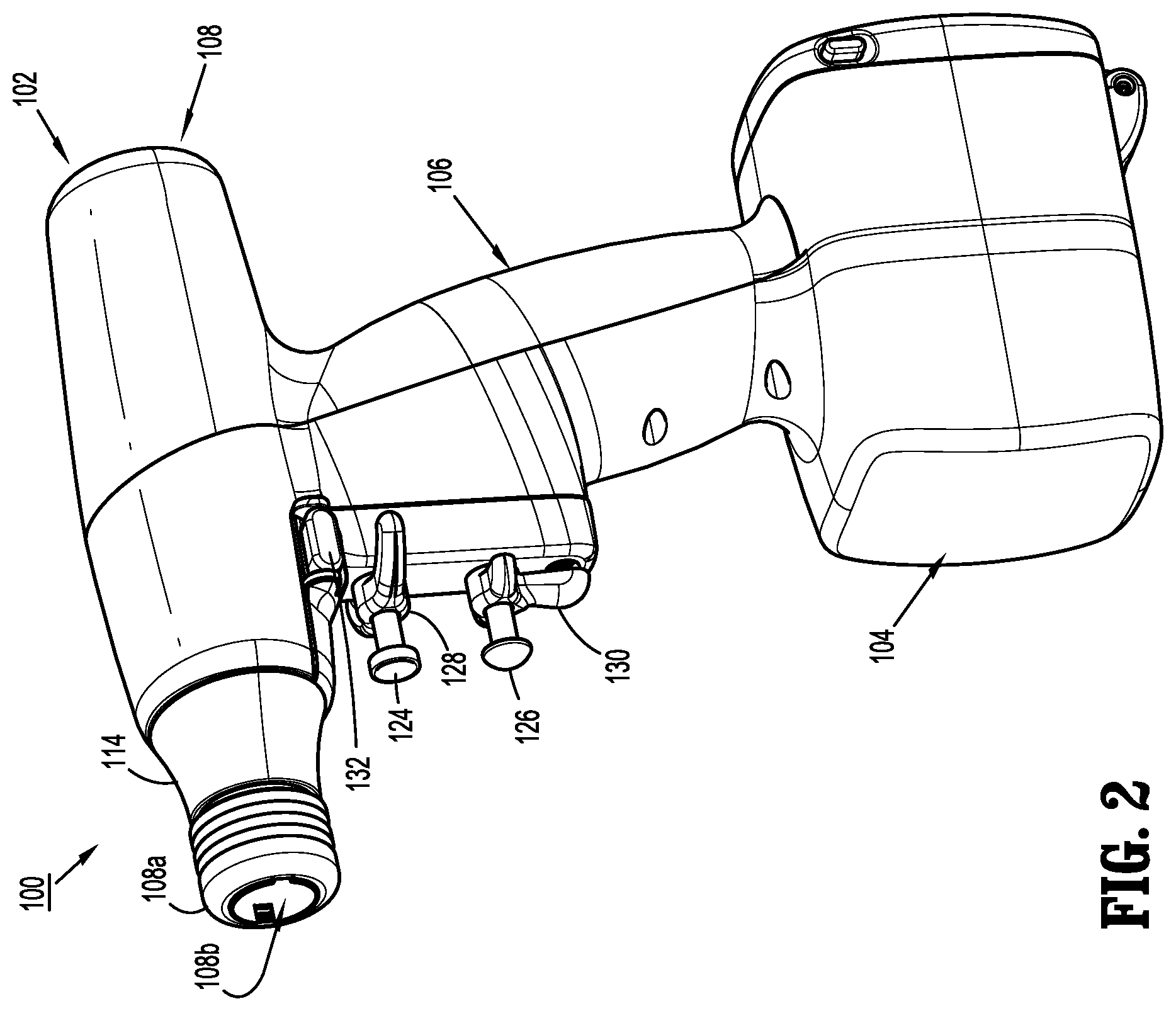
FIG. 2 is a perspective view of the surgical device of FIG. 1;
FIG. 3 is a perspective view of the connecting ends of each of the surgical device and the adapter assembly, illustrating a connection therebetween;
FIG. 4 is a perspective view of the adapter of FIG. 1;
FIG. 5 is a perspective view, with parts separated, of the adapter assembly of FIGS. 1-4;
FIG. 6 is a cross-sectional view of the adapter of FIGS. 1-5, as taken through 6-6 of FIG. 4;
FIG. 7 is a rear, perspective view of an adapter assembly including a knob housing according to another embodiment of the present disclosure;
FIG. 8 is a rear, perspective view of the knob housing of the adapter assembly of FIG. 7;
FIGS. 9 and 10 are perspective, cross-sectional views of the knob housing of FIGS. 7 and 8;
FIG. 11 is a perspective view, with parts separated, of an exemplary end effector for use with the surgical device and the adapter assembly of the present disclosure; and
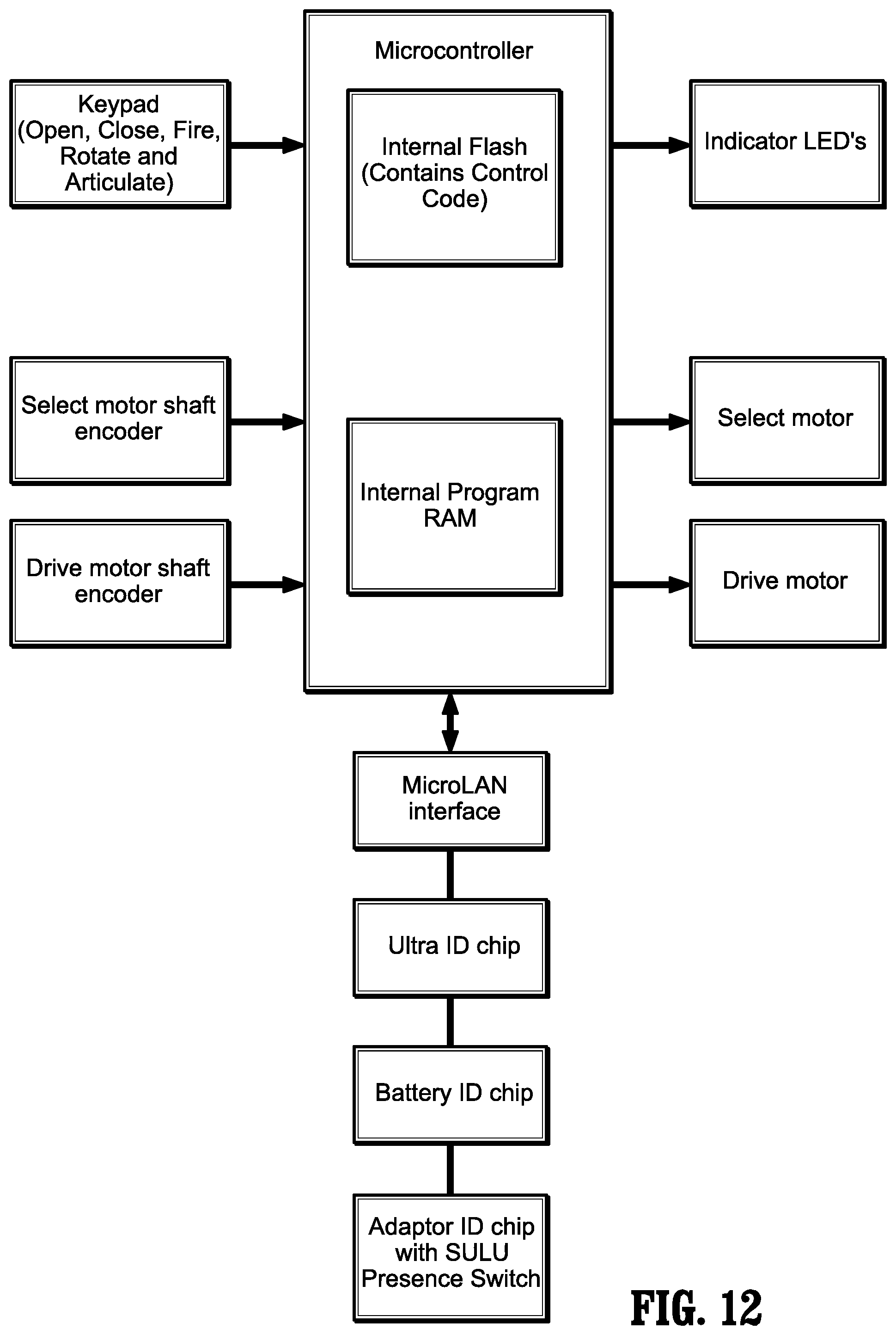
FIG. 12 is a schematic illustration of the outputs to the LED's; selection of motor (to select clamping/cutting, rotation or articulation); and selection of the drive motors to perform a function selected.
DETAILED DESCRIPTION OF EMBODIMENTS
Embodiments of the presently disclosed surgical devices, and adapter assemblies for surgical devices and/or handle assemblies are described in detail with reference to the drawings, in which like reference numerals designate identical or corresponding elements in each of the several views. As used herein the term "distal" refers to that portion of the adapter assembly or surgical device, or component thereof, farther from the user, while the term "proximal" refers to that portion of the adapter assembly or surgical device, or component thereof, closer to the user.
A surgical device, in accordance with an embodiment of the present disclosure, is generally designated as 100, and is in the form of a powered hand held electromechanical instrument configured for selective attachment thereto of a plurality of different end effectors that are each configured for actuation and manipulation by the powered hand held electromechanical surgical instrument.
As illustrated in FIG. 1, surgical device 100 is configured for selective connection with an adapter assembly 200, and, in turn, adapter assembly 200 is configured for selective connection with an end effector or single use loading unit 300.
As illustrated in FIGS. 1 and 2, surgical device 100 includes a handle housing 102 having a lower housing portion 104, an intermediate housing portion 106 extending from and/or supported on lower housing portion 104, and an upper housing portion 108 extending from and/or supported on intermediate housing portion 106. Intermediate housing portion 106 and upper housing portion 108 are separated into a distal half-section that is integrally formed with and extending from the lower portion 104, and a proximal half-section connectable to the distal half-section by a plurality of fasteners. When joined, the distal and proximal half-sections define a handle housing 102 having a cavity therein in which a circuit board (not shown) and a drive mechanism (not shown) is situated.
With reference to FIGS. 1-3, the distal half-section of upper housing portion 108 defines a nose or connecting portion 108a. A nose cone 114 is supported on nose portion 108a of upper housing portion 108. Nose cone 114 is fabricated from a transparent material. An illumination member (not shown) is disposed within nose cone 114 such that the illumination member is visible therethrough. The illumination member may be in the form of a light emitting diode printed circuit board (LED PCB). The illumination member may be configured to illuminate multiple colors with a specific color pattern being associated with a unique discrete event.
Upper housing portion 108 of handle housing 102 provides a housing in which the drive mechanism is situated. The drive mechanism is configured to drive shafts and/or gear components in order to perform the various operations of surgical device 100. In particular, the drive mechanism is configured to drive shafts and/or gear components in order to selectively move tool assembly 304 of end effector 300 (see FIGS. 1 and 11) relative to proximal body portion 302 of end effector 300, to rotate end effector 300 about a longitudinal axis "X" (see FIG. 3) relative to handle housing 102, to move anvil assembly 306 relative to cartridge assembly 308 of end effector 300, and/or to fire a stapling and cutting cartridge within cartridge assembly 308 of end effector 300.
As illustrated in FIGS. 1-3, and as mentioned above, the distal half-section of upper housing portion 108 defines a connecting portion 108a configured to accept a corresponding drive coupling assembly 210 of adapter assembly 200.
As illustrated in FIGS. 2 and 3, connecting portion 108a of surgical device 100 has a cylindrical recess 108b that receives a drive coupling assembly 210 of adapter assembly 200 when adapter assembly 200 is mated to surgical device 100. Connecting portion 108a houses three rotatable drive connectors 118, 120, 122.
When adapter assembly 200 is mated to surgical device 100, each of rotatable drive connectors 118, 120, 122 of surgical device 100 couples with a corresponding rotatable connector sleeve 218, 220, 222 of adapter assembly 200. (see FIG. 3). In this regard, the interface between corresponding first drive connector 118 and first connector sleeve 218, the interface between corresponding second drive connector 120 and second connector sleeve 220, and the interface between corresponding third drive connector 122 and third connector sleeve 222 are keyed such that rotation of each of drive connectors 118, 120, 122 of surgical device 100 causes a corresponding rotation of the corresponding connector sleeve 218, 220, 222 of adapter assembly 200.
The mating of drive connectors 118, 120, 122 of surgical device 100 with connector sleeves 218, 220, 222 of adapter assembly 200 allows rotational forces to be independently transmitted via each of the three respective connector interfaces. The drive connectors 118, 120, 122 of surgical device 100 are configured to be independently rotated by the drive mechanism. In this regard, a function selection module of the drive mechanism selects which drive connector or connectors 118, 120, 122 of surgical device 100 is to be driven by an input drive component of the drive mechanism.
Since each of drive connectors 118, 120, 122 of surgical device 100 has a keyed and/or substantially non-rotatable interface with respective connector sleeves 218, 220, 222 of adapter assembly 200, when adapter assembly 200 is coupled to surgical device 100, rotational force(s) are selectively transferred from the drive mechanism of surgical device 100 to adapter assembly 200.
The selective rotation of drive connector(s) 118, 120 and/or 122 of surgical device 100 allows surgical device 100 to selectively actuate different functions of end effector 300. As will be discussed in greater detail below, selective and independent rotation of first drive connector 118 of surgical device 100 corresponds to the selective and independent opening and closing of tool assembly 304 of end effector 300, and driving of a stapling/cutting component of tool assembly 304 of end effector 300. Also, the selective and independent rotation of second drive connector 120 of surgical device 100 corresponds to the selective and independent articulation of tool assembly 304 of end effector 300 transverse to longitudinal axis "X" (see FIG. 4). Additionally, the selective and independent rotation of third drive connector 122 of surgical device 100 corresponds to the selective and independent rotation of end effector 300 about longitudinal axis "X" (see FIG. 4) relative to handle housing 102 of surgical device 100.
As illustrated in FIGS. 1 and 2, handle housing 102 supports a pair of finger-actuated control buttons 124, 126 and rocker devices 128, 130.
Actuation of first control button 124 causes tool assembly 304 of end effector 300 to close and/or a stapling/cutting cartridge within tool assembly 304 of end effector 300 to fire.
Actuation of rocker device 128 in a first direction causes tool assembly 304 to articulate relative to body portion 302 in a first direction, while actuation of rocker device 128 in an opposite, e.g., second, direction causes tool assembly 304 to articulate relative to body portion 302 in an opposite, e.g., second, direction.
Actuation of control button 126 causes tool assembly 304 of end effector 300 to open.
Actuation of rocker device 130 causes end effector 300 to rotate relative to handle housing 102 of surgical device 100. Specifically, movement of rocker device 130 in a first direction causes end effector 300 to rotate relative to handle housing 102 in a first direction, while movement of rocker device 130 in an opposite, e.g., second, direction causes end effector 300 to rotate relative to handle housing 102 in an opposite, e.g., second, direction.
As illustrated in FIGS. 1-3, surgical device 100 is configured for selective connection with adapter assembly 200, and, in turn, adapter assembly 200 is configured for selective connection with end effector 300.
Adapter assembly 200 is configured to convert a rotation of either of drive connectors 120 and 122 of surgical device 100 into axial translation useful for operating a drive assembly 360 and an articulation link 366 of end effector 300, as illustrated in FIG. 11.
Adapter assembly 200 may include a first drive transmitting/converting assembly for interconnecting third rotatable drive connector 122 of surgical device 100 and a first axially translatable drive member of end effector 300, wherein the first drive transmitting/converting assembly converts and transmits a rotation of third rotatable drive connector 122 of surgical device 100 to an axial translation of the first axially translatable drive assembly 360 (see FIG. 7) of end effector 300 for firing.
Adapter assembly 200 may include a second drive transmitting/converting assembly for interconnecting second rotatable drive connector 120 of surgical device 100 and a second axially translatable drive member of end effector 300, wherein the second drive transmitting/converting assembly converts and transmits a rotation of second rotatable drive connector 120 of surgical device 100 to an axial translation of articulation link 366 (see FIG. 11) of end effector 300 for articulation.
Turning now to FIGS. 1-6, adapter assembly 200 includes a knob housing 202 and an outer tube 206 extending from a distal end of knob housing 202. Knob housing 202 and outer tube 206 are configured and dimensioned to house the components of adapter assembly 200. Outer tube 206 is dimensioned for endoscopic insertion, in particular, that outer tube is passable through a typical trocar port, cannula or the like. Knob housing 202 is dimensioned to not enter the trocar port, cannula of the like.
Knob housing 202 is configured and adapted to connect to connecting portion 108a of upper housing portion 108 of the distal half-section of surgical device 100.
As seen in FIGS. 1-6, adapter assembly 200 includes a surgical device drive coupling assembly 210 at a proximal end thereof and to an end effector coupling assembly 230 at a distal end thereof. Drive coupling assembly 210 includes a distal drive coupling housing 210a and a proximal drive coupling housing 210b rotatably supported, at least partially, in knob housing 202. Drive coupling assembly 210 rotatably supports a first rotatable proximal drive shaft 212 (see FIG. 6), a second rotatable proximal drive shaft 214 (see FIG. 5), and a third rotatable proximal drive shaft 216 (see FIG. 6) therein.
Proximal drive coupling housing 210b is configured to rotatably support first, second and third connector sleeves 218, 220 and 222 (see FIGS. 3 and 6), respectively. Each of connector sleeves 218, 220, 222 is configured to mate with respective first, second and third drive connectors 118, 120, 122 of surgical device 100, as described above. Each of connector sleeves 218, 220, 222 is further configured to mate with a proximal end of respective first, second and third proximal drive shafts 212, 214, 216.
Adapter assembly 200 includes a first, a second and a third drive transmitting/converting assembly, as mentioned above, disposed within handle housing 202 and outer tube 206. Each drive transmitting/converting assembly is configured and adapted to transmit or convert a rotation of a first, second and third drive connector 118, 120, 122 of surgical device 100 into axial translation of a drive tube and a drive bar of adapter assembly 200, to effectuate closing, opening, articulating and firing of end effector 300; or a rotation of adapter assembly 200.
As seen in FIGS. 4-6 and as mentioned above, adapter assembly 200 includes a third drive transmitting/converting assembly. Third drive transmitting/converting assembly is integrally formed in knob housing 202. In FIG. 5, knob housing 202 is shown as having a first half section and a second half section, for illustrative purposes only. In accordance with the scope of the present disclosure, knob housing 202 is formed as a single unitary (one-piece) molded component, devoid of any split half sections. By providing a unitary molded component, knob housing 202 may be more robust as compared to a knob housing having a pair of half sections. It is contemplated that knob housing 202 may be fabricated from plastic or the like using any method known to one having skill in the art.
Knob housing 202 defines a longitudinally extending lumen 202a extending therethrough. Knob housing includes a pair of diametrically opposed bosses 202b, 202c extending radially into lumen 202a. Knob housing 202 further includes an internal ring gear 202d formed in the surface of lumen 202a.
As seen in FIG. 6, the third drive transmitting/converting assembly includes a rotatable proximal drive shaft 216 rotatably supported within housing 202. A proximal end portion of rotatable proximal drive shaft 216 is keyed to third connector 222 of adapter assembly 200. Rotatable proximal drive shaft 216 includes a spur gear 216a keyed to a distal end thereof. A gear set 274 inter-engages spur gear 216a of rotatable proximal drive shaft 216 to the gear teeth of ring gear 202d of knob housing 202. Gear set 274 includes a first gear 274a engaged with spur gear 216a of third rotatable proximal drive shaft 216, and a second gear 274b engaged with the gear teeth of ring gear 202d.
In operation, as rotatable proximal drive shaft 216 is rotated, due to a rotation of third connector sleeve 222, as a result of the rotation of the third respective drive connector 122 of surgical device 100, spur gear 216a of rotatable proximal drive shaft 216 engages first gear 272a of gear set 274 causing gear set 274 to rotate. As gear set 274 rotates, second gear 274b of gear set 274 is rotated and thus causes ring gear 202d to also rotate thereby causing knob housing 202 to rotate. As knob housing 202 is rotated, the pair of diametrically opposed bosses 202b, 202c of knob housing 202 are rotated therewith, thereby transmitting rotation to inner housing tube 206a. As inner housing tube 206a is rotated, distal coupling assembly 230 connected thereto, is caused to be rotated about longitudinal axis "X" of adapter assembly 200. As distal coupling 230 is rotated, end effector 300, that is connected to distal coupling assembly 230, is also caused to be rotated about longitudinal axis "X" of adapter assembly 200.
By forming knob housing 202 as a single unitary component, as compared to an assembly including multiple components manufactured from multiple different materials, knob housing 202 of the present disclosure reduces a relative cost and a relative complexity of shaft assembly 200. In particular, manufacturing time of a single unitary knob housing 202 is reduced as compared to a multi-component knob housing. The overall weight of shaft assembly 200, including a single unitary knob housing 202, will be reduced as compared to a shaft assembly including a multi-component knob housing. The assembly of shaft assembly 200, including a single unitary knob housing 202, will be simplified as compared to the assembly of a shaft assembly including a multi-component knob housing.
Additionally, providing a shaft assembly 200, including a single unitary knob housing 202, will be reduce or eliminate clearances inherently present in shaft assemblies including a multi-component knob housing. By reducing and/or eliminating clearances, a shaft assembly 200, including a single unitary knob housing 202, reduces backlash or play which would otherwise be present in the rotation system (i.e., the third drive transmitting/converting assembly) of surgical device 100 and shaft assembly 200. This will translate into an increase of accuracy from the number input turns to rotation of shaft assembly 200.
Also, the single unitary knob housing 202 will minimize undesired movement and wobbling between the knob housing 202, surgical device drive coupling assembly 210, and outer tube 206.
Turning now to FIGS. 7-10, an adapter assembly 1200 including a knob housing 1202, according to another embodiment of the present disclosure, is shown and will be described. Knob housing 1202 defines a longitudinally extending lumen 1202a extending therethrough. Knob housing 1202 includes a distal housing half 1203a and a proximal housing half or cap 1203b, joined to one another via screw fasteners (not shown) or the like. Proximal housing half 1203b is configured to receive drive coupling assembly 210 therethrough.
Knob housing 1202 further includes an internal ring gear 1202d formed in the surface of lumen 1202a thereof. In particular, internal ring gear 1202d is formed in distal housing half 1203a of knob housing 1202.
As discussed above with regard to adapter assembly 200, adapter assembly 1200 includes a third drive transmitting/converting assembly including a gear set having a spur gear of rotatable proximal drive shaft that engages the gear teeth of ring gear 1202d of knob housing 1202.
Distal housing half 1203a of knob housing 1202 is formed as a single, unitary component (i.e., not split longitudinally). Knob housing 1202, including distal housing half 1203a has all the advantages described above as related to knob housing 202.
In operation, when a button of surgical device 100 is activated by the user, the software checks predefined conditions. If conditions are met, the software controls the motors and delivers mechanical drive to the attached surgical stapler, which can then open, close, rotate, articulate or fire depending on the function of the pressed button. The software also provides feedback to the user by turning colored lights on or off in a defined manner to indicate the status of surgical device 100, adapter assembly 200 and/or end effector 300.
A high level electrical architectural view of the system is displayed in FIG. 12 and shows the connections to the various hardware and software interfaces. Inputs from presses of buttons 124, 126 and from motor encoders of the drive shaft are shown on the left side of FIG. 12. The microcontroller contains the device software that operates surgical device 100, adapter assembly 200 and/or end effector 300. The microcontroller receives inputs from and sends outputs to a MicroLAN, an Ultra ID chip, a Battery ID chip, and Adaptor ID chips.
The MicroLAN, the Ultra ID chip, the Battery ID chip, and the Adaptor ID chips control surgical device 100, adapter assembly 200 and/or end effector 300 as follows:
TABLE-US-00001 MicroLAN -- Serial 1-wire bus communication to read/write system component ID information. Ultra ID chip -- identifies surgical device 100 and records usage information. Battery ID chip -- identifies the Battery 156 and records usage information. Adaptor ID chip -- identifies the type of adapter assembly 200, records the presence of an end effector 300, and records usage information.
The right side of the schematic illustrated in FIG. 12 indicates outputs to the LED's; selection of motor (to select clamping/cutting, rotation or articulation); and selection of the drive motors to perform the function selected.
As illustrated in FIGS. 1 and 11, the end effector is designated as 300. End effector 300 is configured and dimensioned for endoscopic insertion through a cannula, trocar or the like. In particular, in the embodiment illustrated in FIGS. 1 and 11, end effector 300 may pass through a cannula or trocar when end effector 300 is in a closed condition.
End effector 300 includes a proximal body portion 302 and a tool assembly 304. Proximal body portion 302 is releasably attached to a distal coupling 230 of adapter assembly 200 and tool assembly 304 is pivotally attached to a distal end of proximal body portion 302. Tool assembly 304 includes an anvil assembly 306 and a cartridge assembly 308. Cartridge assembly 308 is pivotal in relation to anvil assembly 306 and is movable between an open or unclamped position and a closed or clamped position for insertion through a cannula of a trocar.
Proximal body portion 302 includes at least a drive assembly 360 and an articulation link 366.
Referring to FIG. 11, drive assembly 360 includes a flexible drive beam 364 having a distal end which is secured to a dynamic clamping member 365, and a proximal engagement section 368. Engagement section 368 includes a stepped portion defining a shoulder 370. A proximal end of engagement section 368 includes diametrically opposed inwardly extending fingers 372. Fingers 372 engage a hollow drive member 374 to fixedly secure drive member 374 to the proximal end of beam 364. Drive member 374 defines a proximal porthole 376 which receives connection member 247 of drive tube 246 of first drive converter assembly 240 of adapter assembly 200 when end effector 300 is attached to distal coupling 230 of adapter assembly 200.
When drive assembly 360 is advanced distally within tool assembly 304, an upper beam of clamping member 365 moves within a channel defined between anvil plate 312 and anvil cover 310 and a lower beam moves over the exterior surface of carrier 316 to close tool assembly 304 and fire staples therefrom.
Proximal body portion 302 of end effector 300 includes an articulation link 366 having a hooked proximal end 366a which extends from a proximal end of end effector 300. Hooked proximal end 366a of articulation link 366 engages coupling hook 258c of drive bar 258 of adapter assembly 200 when end effector 300 is secured to distal housing 232 of adapter assembly 200. When drive bar 258 of adapter assembly 200 is advanced or retracted as described above, articulation link 366 of end effector 300 is advanced or retracted within end effector 300 to pivot tool assembly 304 in relation to a distal end of proximal body portion 302.
As illustrated in FIG. 11, cartridge assembly 308 of tool assembly 304 includes a staple cartridge 305 supportable in carrier 316. Staple cartridge 305 defines a central longitudinal slot 305a, and three linear rows of staple retention slots 305b positioned on each side of longitudinal slot 305a. Each of staple retention slots 305b receives a single staple 307 and a portion of a staple pusher 309. During operation of surgical device 100, drive assembly 360 abuts an actuation sled and pushes actuation sled through cartridge 305. As the actuation sled moves through cartridge 305, cam wedges of the actuation sled sequentially engage staple pushers 309 to move staple pushers 309 vertically within staple retention slots 305b and sequentially eject a single staple 307 therefrom for formation against anvil plate 312.
Reference may be made to U.S. Pat. No. 7,819,896, filed on Aug. 31, 2009, entitled "TOOL ASSEMBLY FOR A SURGICAL STAPLING DEVICE," the entire content of which is incorporated herein by reference, for a detailed discussion of the construction and operation of end effector 300.
Reference may also be made to U.S. Pat. No. 9,055,943, filed on May 31, 2012, entitled "HAND HELD SURGICAL HANDLE ASSEMBLY, SURGICAL ADAPTERS FOR USE BETWEEN SURGICAL HANDLE ASSEMBLY AND SURGICAL END EFFECTORS, AND METHODS OF USE," the entire content of which is incorporated herein by reference, for a detailed discussion of the construction and operation of any of the remaining components of surgical device 100, adapter assembly 200, and end effector 300.
It will be understood that various modifications may be made to the embodiments of the presently disclosed adapter assemblies. Therefore, the above description should not be construed as limiting, but merely as exemplifications of embodiments. Those skilled in the art will envision other modifications within the scope and spirit of the present disclosure.
* * * * *
D00000
D00001
D00002
D00003
D00004
D00005
D00006
D00007
D00008
D00009
D00010
D00011
XML
uspto.report is an independent third-party trademark research tool that is not affiliated, endorsed, or sponsored by the United States Patent and Trademark Office (USPTO) or any other governmental organization. The information provided by uspto.report is based on publicly available data at the time of writing and is intended for informational purposes only.
While we strive to provide accurate and up-to-date information, we do not guarantee the accuracy, completeness, reliability, or suitability of the information displayed on this site. The use of this site is at your own risk. Any reliance you place on such information is therefore strictly at your own risk.
All official trademark data, including owner information, should be verified by visiting the official USPTO website at www.uspto.gov. This site is not intended to replace professional legal advice and should not be used as a substitute for consulting with a legal professional who is knowledgeable about trademark law.