Implantable medical device having a sense channel with performance adjustment
Kharam , et al. Feb
U.S. patent number 10,561,330 [Application Number 15/792,353] was granted by the patent office on 2020-02-18 for implantable medical device having a sense channel with performance adjustment. This patent grant is currently assigned to CARDIAC PACEMAKERS, INC.. The grantee listed for this patent is CARDIAC PACEMAKERS, INC.. Invention is credited to Ron A. Balczewski, Paul Huelskamp, Lance Eric Juffer, Aleksandra Kharam, Keith R. Maile.


View All Diagrams
| United States Patent | 10,561,330 |
| Kharam , et al. | February 18, 2020 |
Implantable medical device having a sense channel with performance adjustment
Abstract
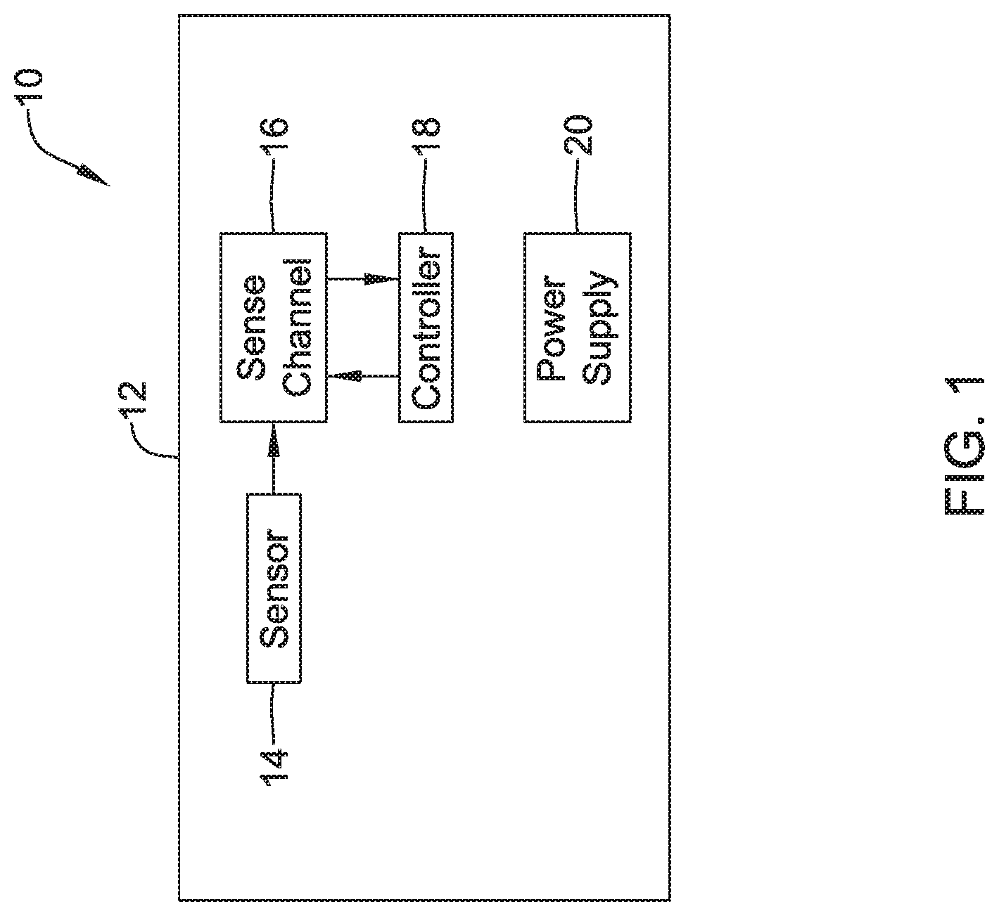
An implantable medical device (IMD) may include a sensor for providing a sensor output signal and a sense channel configured to receive the sensor output signal from the sensor. The sense channel may be configured to process the sensor output signal and output a sense channel output signal. The sense channel may have an adjustable performance level, wherein for a higher performance level the sense channel consumes more power than for a lower performance level. A controller may be configured to adjust the performance level of the sense channel to achieve more performance and more power consumption when a higher degree of sense channel performance is desired and to achieve less performance and less power consumption when a higher degree of performance is not desired.
| Inventors: | Kharam; Aleksandra (Maple Grove, MN), Balczewski; Ron A. (Bloomington, MN), Huelskamp; Paul (St. Paul, MN), Juffer; Lance Eric (Lino Lakes, MN), Maile; Keith R. (New Brighton, MN) | ||||||||||
|---|---|---|---|---|---|---|---|---|---|---|---|
| Applicant: |
|
||||||||||
| Assignee: | CARDIAC PACEMAKERS, INC. (St.
Paul, MN) |
||||||||||
| Family ID: | 60263126 | ||||||||||
| Appl. No.: | 15/792,353 | ||||||||||
| Filed: | October 24, 2017 |
Prior Publication Data
| Document Identifier | Publication Date | |
|---|---|---|
| US 20180116540 A1 | May 3, 2018 | |
Related U.S. Patent Documents
| Application Number | Filing Date | Patent Number | Issue Date | ||
|---|---|---|---|---|---|
| 62413726 | Oct 27, 2016 | ||||
| Current U.S. Class: | 1/1 |
| Current CPC Class: | A61N 1/378 (20130101); A61N 1/37205 (20130101); A61B 5/7221 (20130101); A61N 1/3704 (20130101); A61B 5/0402 (20130101); A61N 1/3708 (20130101); A61B 5/0456 (20130101); A61B 5/686 (20130101); A61N 1/37512 (20170801); A61N 1/37252 (20130101); A61B 5/7203 (20130101); A61N 1/3756 (20130101); A61B 2560/0209 (20130101) |
| Current International Class: | A61B 5/0402 (20060101); A61N 1/37 (20060101); A61N 1/378 (20060101); A61N 1/375 (20060101); A61B 5/00 (20060101); A61B 5/0456 (20060101); A61N 1/372 (20060101) |
References Cited [Referenced By]
U.S. Patent Documents
| 3835864 | September 1974 | Rasor et al. |
| 3943936 | March 1976 | Rasor et al. |
| 4142530 | March 1979 | Wittkampf |
| 4151513 | April 1979 | Menken et al. |
| 4157720 | June 1979 | Greatbatch |
| RE30366 | August 1980 | Rasor et al. |
| 4243045 | January 1981 | Maas |
| 4250884 | February 1981 | Hartlaub et al. |
| 4256115 | March 1981 | Bilitch |
| 4263919 | April 1981 | Levin |
| 4310000 | January 1982 | Lindemans |
| 4312354 | January 1982 | Walters |
| 4323081 | April 1982 | Wiebusch |
| 4357946 | November 1982 | Dutcher et al. |
| 4365639 | December 1982 | Goldreyer |
| 4440173 | April 1984 | Hudziak et al. |
| 4476868 | October 1984 | Thompson |
| 4522208 | June 1985 | Buffet |
| 4537200 | August 1985 | Widrow |
| 4556063 | December 1985 | Thompson et al. |
| 4562841 | January 1986 | Brockway et al. |
| 4593702 | June 1986 | Kepski et al. |
| 4593955 | June 1986 | Leiber |
| 4630611 | December 1986 | King |
| 4635639 | January 1987 | Hakala et al. |
| 4674508 | June 1987 | DeCote |
| 4712554 | December 1987 | Garson |
| 4729376 | March 1988 | DeCote |
| 4754753 | July 1988 | King |
| 4759366 | July 1988 | Callaghan |
| 4776338 | October 1988 | Lekholm et al. |
| 4787389 | November 1988 | Tarjan |
| 4793353 | December 1988 | Borkan |
| 4819662 | April 1989 | Heil et al. |
| 4858610 | August 1989 | Callaghan et al. |
| 4886064 | December 1989 | Strandberg |
| 4887609 | December 1989 | Cole |
| 4928688 | May 1990 | Mower |
| 4967746 | November 1990 | Vandegriff |
| 4987897 | January 1991 | Funke |
| 4989602 | February 1991 | Sholder et al. |
| 5012806 | May 1991 | De Bellis |
| 5036849 | August 1991 | Hauck et al. |
| 5040534 | August 1991 | Mann et al. |
| 5058581 | October 1991 | Silvian |
| 5078134 | January 1992 | Heilman et al. |
| 5109845 | May 1992 | Yuuchi et al. |
| 5113859 | May 1992 | Funke |
| 5113869 | May 1992 | Nappholz et al. |
| 5117824 | June 1992 | Keimel et al. |
| 5127401 | July 1992 | Grevious et al. |
| 5133353 | July 1992 | Hauser |
| 5144950 | September 1992 | Stoop et al. |
| 5170784 | December 1992 | Ramon et al. |
| 5179945 | January 1993 | Van Hofwegen et al. |
| 5193539 | March 1993 | Schulman et al. |
| 5193540 | March 1993 | Schulman et al. |
| 5241961 | September 1993 | Henry |
| 5243977 | September 1993 | Trabucco et al. |
| 5259387 | November 1993 | DePinto |
| 5269326 | December 1993 | Verrier |
| 5284136 | February 1994 | Hauck et al. |
| 5300107 | April 1994 | Stokes et al. |
| 5301677 | April 1994 | Hsung |
| 5305760 | April 1994 | McKown et al. |
| 5312439 | May 1994 | Loeb |
| 5313953 | May 1994 | Yomtov et al. |
| 5314459 | May 1994 | Swanson et al. |
| 5318597 | June 1994 | Hauck et al. |
| 5324316 | June 1994 | Schulman et al. |
| 5331966 | July 1994 | Bennett et al. |
| 5334222 | August 1994 | Salo et al. |
| 5342408 | August 1994 | deCoriolis et al. |
| 5370667 | December 1994 | Alt |
| 5372606 | December 1994 | Lang et al. |
| 5376106 | December 1994 | Stahmann et al. |
| 5383915 | January 1995 | Adams |
| 5388578 | February 1995 | Yomtov et al. |
| 5404877 | April 1995 | Nolan et al. |
| 5405367 | April 1995 | Schulman et al. |
| 5411031 | May 1995 | Yomtov |
| 5411525 | May 1995 | Swanson et al. |
| 5411535 | May 1995 | Fujii et al. |
| 5456691 | October 1995 | Snell |
| 5458622 | October 1995 | Alt |
| 5466246 | November 1995 | Silvian |
| 5468254 | November 1995 | Hahn et al. |
| 5472453 | December 1995 | Alt |
| 5522866 | June 1996 | Fernald |
| 5540727 | July 1996 | Tockman et al. |
| 5545186 | August 1996 | Olson et al. |
| 5545202 | August 1996 | Dahl et al. |
| 5571146 | November 1996 | Jones et al. |
| 5591214 | January 1997 | Lu |
| 5620466 | April 1997 | Haefner et al. |
| 5634938 | June 1997 | Swanson et al. |
| 5649968 | July 1997 | Alt et al. |
| 5662688 | September 1997 | Haefner et al. |
| 5674259 | October 1997 | Gray |
| 5683426 | November 1997 | Greenhut et al. |
| 5683432 | November 1997 | Goedeke et al. |
| 5706823 | January 1998 | Wodlinger |
| 5709215 | January 1998 | Perttu et al. |
| 5720770 | February 1998 | Nappholz et al. |
| 5728154 | March 1998 | Crossett et al. |
| 5741314 | April 1998 | Daly et al. |
| 5741315 | April 1998 | Lee et al. |
| 5752976 | May 1998 | Duffin et al. |
| 5752977 | May 1998 | Grevious et al. |
| 5755736 | May 1998 | Gillberg et al. |
| 5759199 | June 1998 | Snell et al. |
| 5774501 | June 1998 | Halpern et al. |
| 5792195 | August 1998 | Carlson et al. |
| 5792202 | August 1998 | Rueter |
| 5792203 | August 1998 | Schroeppel |
| 5792205 | August 1998 | Alt et al. |
| 5792208 | August 1998 | Gray |
| 5814089 | September 1998 | Stokes et al. |
| 5827216 | October 1998 | Igo et al. |
| 5836985 | November 1998 | Rostami et al. |
| 5836987 | November 1998 | Baumann et al. |
| 5842977 | December 1998 | Lesho et al. |
| 5855593 | January 1999 | Olson et al. |
| 5861009 | January 1999 | Armstrong et al. |
| 5873894 | February 1999 | Vandegriff et al. |
| 5891184 | April 1999 | Lee et al. |
| 5897586 | April 1999 | Molina |
| 5899876 | May 1999 | Flower |
| 5899928 | May 1999 | Sholder et al. |
| 5919214 | July 1999 | Ciciarelli et al. |
| 5935078 | August 1999 | Feierbach |
| 5941906 | August 1999 | Barreras, Sr. et al. |
| 5944744 | August 1999 | Paul et al. |
| 5954757 | September 1999 | Gray |
| 5978713 | November 1999 | Prutchi et al. |
| 5991660 | November 1999 | Goyal |
| 5991661 | November 1999 | Park et al. |
| 5999848 | December 1999 | Gord et al. |
| 5999857 | December 1999 | Weijand et al. |
| 6016445 | January 2000 | Baura |
| 6026320 | February 2000 | Carlson et al. |
| 6029085 | February 2000 | Olson et al. |
| 6041250 | March 2000 | DePinto |
| 6044298 | March 2000 | Salo et al. |
| 6044300 | March 2000 | Gray |
| 6055454 | April 2000 | Heemels |
| 6073050 | June 2000 | Griffith |
| 6076016 | June 2000 | Feierbach |
| 6077236 | June 2000 | Cunningham |
| 6080187 | June 2000 | Alt et al. |
| 6083248 | July 2000 | Thompson |
| 6106551 | August 2000 | Crossett et al. |
| 6115636 | September 2000 | Ryan |
| 6128526 | October 2000 | Stadler et al. |
| 6141581 | October 2000 | Olson et al. |
| 6141583 | October 2000 | Pape et al. |
| 6141588 | October 2000 | Cox et al. |
| 6141592 | October 2000 | Pauly |
| 6144879 | November 2000 | Gray |
| 6162195 | December 2000 | Igo et al. |
| 6164284 | December 2000 | Schulman et al. |
| 6167303 | December 2000 | Thompson |
| 6167310 | December 2000 | Grevious |
| 6201993 | March 2001 | Kruse et al. |
| 6208894 | March 2001 | Schulman et al. |
| 6211799 | April 2001 | Post et al. |
| 6221011 | April 2001 | Bardy |
| 6240316 | May 2001 | Richmond et al. |
| 6240317 | May 2001 | Villaseca et al. |
| 6256534 | July 2001 | Dahl |
| 6259947 | July 2001 | Olson et al. |
| 6266558 | July 2001 | Gozani et al. |
| 6266567 | July 2001 | Ishikawa et al. |
| 6270457 | August 2001 | Bardy |
| 6272377 | August 2001 | Sweeney et al. |
| 6273856 | August 2001 | Sun et al. |
| 6277072 | August 2001 | Bardy |
| 6280380 | August 2001 | Bardy |
| 6285907 | September 2001 | Kramer et al. |
| 6292698 | September 2001 | Duffin et al. |
| 6295473 | September 2001 | Rosar |
| 6297943 | October 2001 | Carson |
| 6298271 | October 2001 | Weijand |
| 6307751 | October 2001 | Bodony et al. |
| 6312378 | November 2001 | Bardy |
| 6315721 | November 2001 | Schulman et al. |
| 6336903 | January 2002 | Bardy |
| 6345202 | February 2002 | Richmond et al. |
| 6351667 | February 2002 | Godie |
| 6351669 | February 2002 | Hartley et al. |
| 6353759 | March 2002 | Hartley et al. |
| 6358203 | March 2002 | Bardy |
| 6361780 | March 2002 | Ley et al. |
| 6366812 | April 2002 | Levine et al. |
| 6368284 | April 2002 | Bardy |
| 6371922 | April 2002 | Baumann et al. |
| 6398728 | June 2002 | Bardy |
| 6400982 | June 2002 | Sweeney et al. |
| 6400990 | June 2002 | Silvian |
| 6408208 | June 2002 | Sun |
| 6409674 | June 2002 | Brockway et al. |
| 6411848 | June 2002 | Kramer et al. |
| 6424865 | July 2002 | Ding |
| 6434429 | August 2002 | Kraus et al. |
| 6438410 | August 2002 | Hsu et al. |
| 6438417 | August 2002 | Rockwell et al. |
| 6438421 | August 2002 | Stahmann et al. |
| 6440066 | August 2002 | Bardy |
| 6441747 | August 2002 | Khair et al. |
| 6442426 | August 2002 | Kroll |
| 6442432 | August 2002 | Lee |
| 6443891 | September 2002 | Grevious |
| 6445953 | September 2002 | Bulkes et al. |
| 6453200 | September 2002 | Koslar |
| 6459929 | October 2002 | Hopper et al. |
| 6470215 | October 2002 | Kraus et al. |
| 6471645 | October 2002 | Warkentin et al. |
| 6480745 | November 2002 | Nelson et al. |
| 6487443 | November 2002 | Olson et al. |
| 6490487 | December 2002 | Kraus et al. |
| 6498951 | December 2002 | Larson et al. |
| 6507755 | January 2003 | Gozani et al. |
| 6507759 | January 2003 | Prutchi et al. |
| 6512940 | January 2003 | Brabec et al. |
| 6522915 | February 2003 | Ceballos et al. |
| 6526311 | February 2003 | Begemann |
| 6539253 | March 2003 | Thompson et al. |
| 6542775 | April 2003 | Ding et al. |
| 6553258 | April 2003 | Stahmann et al. |
| 6561975 | May 2003 | Pool et al. |
| 6564807 | May 2003 | Schulman et al. |
| 6574506 | June 2003 | Kramer et al. |
| 6584351 | June 2003 | Ekwall |
| 6584352 | June 2003 | Combs et al. |
| 6597948 | July 2003 | Rockwell et al. |
| 6597951 | July 2003 | Kramer et al. |
| 6622045 | September 2003 | Snell et al. |
| 6622046 | September 2003 | Fraley et al. |
| 6628985 | September 2003 | Sweeney et al. |
| 6647292 | November 2003 | Bardy et al. |
| 6666844 | December 2003 | Igo et al. |
| 6689117 | February 2004 | Sweeney et al. |
| 6690959 | February 2004 | Thompson |
| 6694189 | February 2004 | Begemann |
| 6704602 | March 2004 | Berg et al. |
| 6718212 | April 2004 | Parry et al. |
| 6721597 | April 2004 | Bardy et al. |
| 6738670 | May 2004 | Almendinger et al. |
| 6746797 | June 2004 | Benson et al. |
| 6749566 | June 2004 | Russ |
| 6758810 | July 2004 | Lebel et al. |
| 6763269 | July 2004 | Cox |
| 6778860 | August 2004 | Ostroff et al. |
| 6788971 | September 2004 | Sloman et al. |
| 6788974 | September 2004 | Bardy et al. |
| 6804558 | October 2004 | Haller et al. |
| 6807442 | October 2004 | Myklebust et al. |
| 6847844 | January 2005 | Sun et al. |
| 6871095 | March 2005 | Stahmann et al. |
| 6878112 | April 2005 | Linberg et al. |
| 6885889 | April 2005 | Chinchoy |
| 6892094 | May 2005 | Ousdigian et al. |
| 6897788 | May 2005 | Khair et al. |
| 6904315 | June 2005 | Panken et al. |
| 6922592 | July 2005 | Thompson et al. |
| 6931282 | August 2005 | Esler |
| 6934585 | August 2005 | Schloss et al. |
| 6957107 | October 2005 | Rogers et al. |
| 6978176 | December 2005 | Lattouf |
| 6985773 | January 2006 | Von Arx et al. |
| 6990375 | January 2006 | Kloss et al. |
| 7001366 | February 2006 | Ballard |
| 7003350 | February 2006 | Denker et al. |
| 7006864 | February 2006 | Echt et al. |
| 7013178 | March 2006 | Reinke et al. |
| 7027871 | April 2006 | Burnes et al. |
| 7050849 | May 2006 | Echt et al. |
| 7060031 | June 2006 | Webb et al. |
| 7063693 | June 2006 | Guenst |
| 7082336 | July 2006 | Ransbury et al. |
| 7085606 | August 2006 | Flach et al. |
| 7092758 | August 2006 | Sun et al. |
| 7110824 | September 2006 | Amundson et al. |
| 7120504 | October 2006 | Osypka |
| 7130681 | October 2006 | Gebhardt et al. |
| 7139613 | November 2006 | Reinke et al. |
| 7142912 | November 2006 | Wagner et al. |
| 7146225 | December 2006 | Guenst et al. |
| 7146226 | December 2006 | Lau et al. |
| 7149581 | December 2006 | Goedeke |
| 7149588 | December 2006 | Lau et al. |
| 7158839 | January 2007 | Lau |
| 7162307 | January 2007 | Patrias |
| 7164952 | January 2007 | Lau et al. |
| 7177700 | February 2007 | Cox |
| 7181505 | February 2007 | Haller et al. |
| 7184830 | February 2007 | Echt et al. |
| 7186214 | March 2007 | Ness |
| 7191015 | March 2007 | Lamson et al. |
| 7200437 | April 2007 | Nabutovsky et al. |
| 7200439 | April 2007 | Zdeblick et al. |
| 7206423 | April 2007 | Feng et al. |
| 7209785 | April 2007 | Kim et al. |
| 7209790 | April 2007 | Thompson et al. |
| 7211884 | May 2007 | Davis et al. |
| 7212871 | May 2007 | Morgan |
| 7226440 | June 2007 | Gelfand et al. |
| 7228183 | June 2007 | Sun et al. |
| 7236821 | June 2007 | Cates et al. |
| 7236829 | June 2007 | Farazi et al. |
| 7254448 | August 2007 | Almendinger et al. |
| 7260436 | August 2007 | Kilgore et al. |
| 7270669 | September 2007 | Sra |
| 7272448 | September 2007 | Morgan et al. |
| 7277755 | October 2007 | Falkenberg et al. |
| 7280872 | October 2007 | Mosesov et al. |
| 7288096 | October 2007 | Chin |
| 7289847 | October 2007 | Gill et al. |
| 7289852 | October 2007 | Helfinstine et al. |
| 7289853 | October 2007 | Campbell et al. |
| 7289855 | October 2007 | Nghiem et al. |
| 7302294 | November 2007 | Kamath et al. |
| 7305266 | December 2007 | Kroll |
| 7310556 | December 2007 | Bulkes |
| 7319905 | January 2008 | Morgan et al. |
| 7321798 | January 2008 | Muhlenberg et al. |
| 7333853 | February 2008 | Mazar et al. |
| 7336994 | February 2008 | Hettrick et al. |
| 7345607 | March 2008 | Frigaard et al. |
| 7347819 | March 2008 | Lebel et al. |
| 7366572 | April 2008 | Heruth et al. |
| 7373207 | May 2008 | Lattouf |
| 7384403 | June 2008 | Sherman |
| 7386342 | June 2008 | Falkenberg et al. |
| 7392090 | June 2008 | Sweeney et al. |
| 7406105 | July 2008 | DelMain et al. |
| 7406349 | July 2008 | Seeberger et al. |
| 7410497 | August 2008 | Hastings et al. |
| 7425200 | September 2008 | Brockway et al. |
| 7433739 | October 2008 | Salys et al. |
| 7496409 | February 2009 | Greenhut et al. |
| 7496410 | February 2009 | Heil |
| 7502652 | March 2009 | Gaunt et al. |
| 7512448 | March 2009 | Malick et al. |
| 7515969 | April 2009 | Tockman et al. |
| 7526342 | April 2009 | Chin et al. |
| 7529589 | May 2009 | Williams et al. |
| 7532933 | May 2009 | Hastings et al. |
| 7536222 | May 2009 | Bardy et al. |
| 7536224 | May 2009 | Ritscher et al. |
| 7539541 | May 2009 | Quiles et al. |
| 7544197 | June 2009 | Kelsch et al. |
| 7558631 | July 2009 | Cowan et al. |
| 7565195 | July 2009 | Kroll et al. |
| 7584002 | September 2009 | Burnes et al. |
| 7590455 | September 2009 | Heruth et al. |
| 7606621 | October 2009 | Brisken et al. |
| 7610088 | October 2009 | Chinchoy |
| 7610092 | October 2009 | Cowan et al. |
| 7610099 | October 2009 | Almendinger et al. |
| 7610104 | October 2009 | Kaplan et al. |
| 7616991 | November 2009 | Mann et al. |
| 7617001 | November 2009 | Penner et al. |
| 7617007 | November 2009 | Williams et al. |
| 7630767 | December 2009 | Poore et al. |
| 7634313 | December 2009 | Kroll et al. |
| 7637867 | December 2009 | Zdeblick |
| 7640060 | December 2009 | Zdeblick |
| 7647109 | January 2010 | Hastings et al. |
| 7650186 | January 2010 | Hastings et al. |
| 7657311 | February 2010 | Bardy et al. |
| 7668596 | February 2010 | Von Arx et al. |
| 7682316 | March 2010 | Anderson et al. |
| 7691047 | April 2010 | Ferrari |
| 7702392 | April 2010 | Echt et al. |
| 7713194 | May 2010 | Zdeblick |
| 7713195 | May 2010 | Zdeblick |
| 7729783 | June 2010 | Michels et al. |
| 7734333 | June 2010 | Ghanem et al. |
| 7734343 | June 2010 | Ransbury et al. |
| 7738958 | June 2010 | Zdeblick et al. |
| 7738964 | June 2010 | Von Arx et al. |
| 7742812 | June 2010 | Ghanem et al. |
| 7742816 | June 2010 | Masoud et al. |
| 7742822 | June 2010 | Masoud et al. |
| 7743151 | June 2010 | Vallapureddy et al. |
| 7747335 | June 2010 | Williams |
| 7751881 | July 2010 | Cowan et al. |
| 7758521 | July 2010 | Morris et al. |
| 7761150 | July 2010 | Ghanem et al. |
| 7761164 | July 2010 | Verhoef et al. |
| 7765001 | July 2010 | Echt et al. |
| 7769452 | August 2010 | Ghanem et al. |
| 7783362 | August 2010 | Whitehurst et al. |
| 7792588 | September 2010 | Harding |
| 7797059 | September 2010 | Bornzin et al. |
| 7801596 | September 2010 | Fischell et al. |
| 7809438 | October 2010 | Echt et al. |
| 7840281 | November 2010 | Kveen et al. |
| 7844331 | November 2010 | Li et al. |
| 7844348 | November 2010 | Swoyer et al. |
| 7846088 | December 2010 | Ness |
| 7848815 | December 2010 | Brisken et al. |
| 7848823 | December 2010 | Drasler et al. |
| 7860455 | December 2010 | Fukumoto et al. |
| 7871433 | January 2011 | Lattouf |
| 7877136 | January 2011 | Moffitt et al. |
| 7877142 | January 2011 | Moaddeb et al. |
| 7881786 | February 2011 | Jackson |
| 7881798 | February 2011 | Miesel et al. |
| 7881810 | February 2011 | Chitre et al. |
| 7890173 | February 2011 | Brisken et al. |
| 7890181 | February 2011 | Denzene et al. |
| 7890192 | February 2011 | Kelsch et al. |
| 7894885 | February 2011 | Bartal et al. |
| 7894894 | February 2011 | Stadler et al. |
| 7894907 | February 2011 | Cowan et al. |
| 7894910 | February 2011 | Cowan et al. |
| 7894915 | February 2011 | Chitre et al. |
| 7899537 | March 2011 | Kroll et al. |
| 7899541 | March 2011 | Cowan et al. |
| 7899542 | March 2011 | Cowan et al. |
| 7899554 | March 2011 | Williams et al. |
| 7901360 | March 2011 | Yang et al. |
| 7904170 | March 2011 | Harding |
| 7907993 | March 2011 | Ghanem et al. |
| 7920928 | April 2011 | Yang et al. |
| 7925343 | April 2011 | Min et al. |
| 7930022 | April 2011 | Zhang et al. |
| 7930040 | April 2011 | Kelsch et al. |
| 7937135 | May 2011 | Ghanem et al. |
| 7937148 | May 2011 | Jacobson |
| 7937161 | May 2011 | Hastings et al. |
| 7941214 | May 2011 | Kleckner et al. |
| 7945333 | May 2011 | Jacobson |
| 7946997 | May 2011 | Hubinette |
| 7949404 | May 2011 | Hill |
| 7949405 | May 2011 | Feher |
| 7953486 | May 2011 | Daum et al. |
| 7953493 | May 2011 | Fowler et al. |
| 7962202 | June 2011 | Bhunia |
| 7974702 | July 2011 | Fain et al. |
| 7979136 | July 2011 | Young et al. |
| 7983753 | July 2011 | Severin |
| 7991467 | August 2011 | Markowitz et al. |
| 7991471 | August 2011 | Ghanem et al. |
| 7996087 | August 2011 | Cowan et al. |
| 8000791 | August 2011 | Sunagawa et al. |
| 8000807 | August 2011 | Morris et al. |
| 8001975 | August 2011 | DiSilvestro et al. |
| 8002700 | August 2011 | Ferek-Petric et al. |
| 8010209 | August 2011 | Jacobson |
| 8019419 | September 2011 | Panescu et al. |
| 8019434 | September 2011 | Quiles et al. |
| 8027727 | September 2011 | Freeberg |
| 8027729 | September 2011 | Sunagawa et al. |
| 8032219 | October 2011 | Neumann et al. |
| 8036743 | October 2011 | Savage et al. |
| 8046079 | October 2011 | Bange et al. |
| 8046080 | October 2011 | Von Arx et al. |
| 8050297 | November 2011 | DelMain et al. |
| 8050759 | November 2011 | Stegemann et al. |
| 8050774 | November 2011 | Kveen et al. |
| 8055345 | November 2011 | Li et al. |
| 8055350 | November 2011 | Roberts |
| 8060212 | November 2011 | Rios et al. |
| 8065018 | November 2011 | Haubrich et al. |
| 8073542 | December 2011 | Doerr |
| 8078278 | December 2011 | Penner |
| 8078283 | December 2011 | Cowan et al. |
| 8095123 | January 2012 | Gray |
| 8102789 | January 2012 | Rosar et al. |
| 8103359 | January 2012 | Reddy |
| 8103361 | January 2012 | Moser |
| 8112148 | February 2012 | Giftakis et al. |
| 8114021 | February 2012 | Robertson et al. |
| 8121680 | February 2012 | Falkenberg et al. |
| 8123684 | February 2012 | Zdeblick |
| 8126545 | February 2012 | Flach et al. |
| 8131334 | March 2012 | Lu et al. |
| 8140161 | March 2012 | Willerton et al. |
| 8150521 | April 2012 | Crowley et al. |
| 8160672 | April 2012 | Kim et al. |
| 8160702 | April 2012 | Mann et al. |
| 8160704 | April 2012 | Freeberg |
| 8165694 | April 2012 | Carbanaru et al. |
| 8175715 | May 2012 | Cox |
| 8180451 | May 2012 | Hickman et al. |
| 8185213 | May 2012 | Kveen et al. |
| 8187161 | May 2012 | Li et al. |
| 8195293 | June 2012 | Limousin et al. |
| 8204595 | June 2012 | Pianca et al. |
| 8204605 | June 2012 | Hastings et al. |
| 8209014 | June 2012 | Doerr |
| 8214043 | July 2012 | Matos |
| 8224244 | July 2012 | Kim et al. |
| 8229556 | July 2012 | Li |
| 8233985 | July 2012 | Bulkes et al. |
| 8262578 | September 2012 | Bharmi et al. |
| 8265748 | September 2012 | Liu et al. |
| 8265757 | September 2012 | Mass et al. |
| 8280521 | October 2012 | Haubrich et al. |
| 8285387 | October 2012 | Utsi et al. |
| 8290598 | October 2012 | Boon et al. |
| 8290600 | October 2012 | Hastings et al. |
| 8295939 | October 2012 | Jacobson |
| 8301254 | October 2012 | Mosesov et al. |
| 8315701 | November 2012 | Cowan et al. |
| 8315708 | November 2012 | Berthelsdorf et al. |
| 8321021 | November 2012 | Kisker et al. |
| 8321036 | November 2012 | Brockway et al. |
| 8332036 | December 2012 | Hastings et al. |
| 8335563 | December 2012 | Stessman |
| 8335568 | December 2012 | Heruth et al. |
| 8340750 | December 2012 | Prakash et al. |
| 8340780 | December 2012 | Hastings et al. |
| 8352025 | January 2013 | Jacobson |
| 8352028 | January 2013 | Wenger |
| 8352038 | January 2013 | Mao et al. |
| 8359098 | January 2013 | Lund et al. |
| 8364261 | January 2013 | Stubbs et al. |
| 8364276 | January 2013 | Willis |
| 8369959 | February 2013 | Meskens |
| 8369962 | February 2013 | Abrahamson |
| 8380320 | February 2013 | Spital |
| 8386051 | February 2013 | Rys |
| 8391981 | March 2013 | Mosesov |
| 8391990 | March 2013 | Smith et al. |
| 8406874 | March 2013 | Liu et al. |
| 8406879 | March 2013 | Shuros et al. |
| 8406886 | March 2013 | Gaunt et al. |
| 8412352 | April 2013 | Griswold et al. |
| 8417340 | April 2013 | Goossen |
| 8417341 | April 2013 | Freeberg |
| 8423149 | April 2013 | Hennig |
| 8428722 | April 2013 | Verhoef et al. |
| 8433402 | April 2013 | Ruben et al. |
| 8433409 | April 2013 | Johnson et al. |
| 8433420 | April 2013 | Bange et al. |
| 8447412 | May 2013 | Dal Molin et al. |
| 8452413 | May 2013 | Young et al. |
| 8457740 | June 2013 | Osche |
| 8457742 | June 2013 | Jacobson |
| 8457744 | June 2013 | Janzig et al. |
| 8457761 | June 2013 | Wariar |
| 8478407 | July 2013 | Demmer et al. |
| 8478408 | July 2013 | Hastings et al. |
| 8478431 | July 2013 | Griswold et al. |
| 8494632 | July 2013 | Sun et al. |
| 8504156 | August 2013 | Bonner et al. |
| 8509910 | August 2013 | Sowder et al. |
| 8515559 | August 2013 | Roberts et al. |
| 8525340 | September 2013 | Eckhardt et al. |
| 8527068 | September 2013 | Ostroff |
| 8532790 | September 2013 | Griswold |
| 8538526 | September 2013 | Stahmann et al. |
| 8541131 | September 2013 | Lund et al. |
| 8543205 | September 2013 | Ostroff |
| 8547248 | October 2013 | Zdeblick et al. |
| 8548605 | October 2013 | Ollivier |
| 8554333 | October 2013 | Wu et al. |
| 8565882 | October 2013 | Matos |
| 8565897 | October 2013 | Regnier et al. |
| 8571678 | October 2013 | Wang |
| 8577327 | November 2013 | Makdissi et al. |
| 8588926 | November 2013 | Moore et al. |
| 8612002 | December 2013 | Faltys et al. |
| 8615310 | December 2013 | Khairkhahan et al. |
| 8626280 | January 2014 | Allavatam et al. |
| 8626294 | January 2014 | Sheldon et al. |
| 8634908 | January 2014 | Cowan |
| 8634912 | January 2014 | Bornzin et al. |
| 8634919 | January 2014 | Hou et al. |
| 8639335 | January 2014 | Peichel et al. |
| 8644934 | February 2014 | Hastings et al. |
| 8649859 | February 2014 | Smith et al. |
| 8670842 | March 2014 | Bornzin et al. |
| 8676319 | March 2014 | Knoll |
| 8676335 | March 2014 | Katoozi et al. |
| 8694097 | April 2014 | Cao |
| 8700173 | April 2014 | Edlund |
| 8700181 | April 2014 | Bornzin et al. |
| 8705599 | April 2014 | dal Molin et al. |
| 8718766 | May 2014 | Wahlberg |
| 8718773 | May 2014 | Willis et al. |
| 8725260 | May 2014 | Shuros et al. |
| 8738133 | May 2014 | Shuros et al. |
| 8738147 | May 2014 | Hastings et al. |
| 8744555 | June 2014 | Allavatam et al. |
| 8744572 | June 2014 | Greenhut et al. |
| 8747314 | June 2014 | Stahmann et al. |
| 8755884 | June 2014 | Demmer et al. |
| 8758365 | June 2014 | Bonner et al. |
| 8768483 | July 2014 | Schmitt et al. |
| 8774572 | July 2014 | Hamamoto |
| 8781605 | July 2014 | Bornzin et al. |
| 8788035 | July 2014 | Jacobson |
| 8788053 | July 2014 | Jacobson |
| 8798740 | August 2014 | Samade et al. |
| 8798745 | August 2014 | Jacobson |
| 8798762 | August 2014 | Fain et al. |
| 8798770 | August 2014 | Reddy |
| 8805505 | August 2014 | Roberts |
| 8805528 | August 2014 | Corndorf |
| 8812109 | August 2014 | Blomqvist et al. |
| 8818504 | August 2014 | Bodner et al. |
| 8827913 | September 2014 | Havel et al. |
| 8831747 | September 2014 | Min et al. |
| 8855789 | October 2014 | Jacobson |
| 8868186 | October 2014 | Kroll |
| 8886339 | November 2014 | Faltys et al. |
| 8903473 | December 2014 | Rogers et al. |
| 8903500 | December 2014 | Smith et al. |
| 8903513 | December 2014 | Ollivier |
| 8909336 | December 2014 | Navarro-Paredes et al. |
| 8914131 | December 2014 | Bornzin et al. |
| 8923795 | December 2014 | Makdissi et al. |
| 8923963 | December 2014 | Bonner et al. |
| 8938300 | January 2015 | Rosero |
| 8942806 | January 2015 | Sheldon et al. |
| 8958892 | February 2015 | Khairkhahan et al. |
| 8977358 | March 2015 | Ewert et al. |
| 8989873 | March 2015 | Locsin |
| 8996109 | March 2015 | Karst et al. |
| 9002467 | April 2015 | Smith et al. |
| 9008776 | April 2015 | Cowan et al. |
| 9008777 | April 2015 | Dianaty et al. |
| 9014818 | April 2015 | Deterre et al. |
| 9017341 | April 2015 | Bornzin et al. |
| 9020611 | April 2015 | Khairkhahan et al. |
| 9037262 | May 2015 | Regnier et al. |
| 9042984 | May 2015 | Demmer et al. |
| 9072911 | July 2015 | Hastings et al. |
| 9072913 | July 2015 | Jacobson |
| 9155882 | October 2015 | Grubac et al. |
| 9168372 | October 2015 | Fain |
| 9168380 | October 2015 | Greenhut et al. |
| 9168383 | October 2015 | Jacobson et al. |
| 9180285 | November 2015 | Moore et al. |
| 9192774 | November 2015 | Jacobson |
| 9205225 | December 2015 | Khairkhahan et al. |
| 9216285 | December 2015 | Boling et al. |
| 9216293 | December 2015 | Berthiaume et al. |
| 9216298 | December 2015 | Jacobson |
| 9227077 | January 2016 | Jacobson |
| 9238145 | January 2016 | Wenzel et al. |
| 9242102 | January 2016 | Khairkhahan et al. |
| 9242113 | January 2016 | Smith et al. |
| 9248300 | February 2016 | Rys et al. |
| 9265436 | February 2016 | Min et al. |
| 9265962 | February 2016 | Dianaty et al. |
| 9272155 | March 2016 | Ostroff |
| 9278218 | March 2016 | Karst et al. |
| 9278229 | March 2016 | Reinke et al. |
| 9283381 | March 2016 | Grubac et al. |
| 9283382 | March 2016 | Berthiaume et al. |
| 9289612 | March 2016 | Sambelashvili et al. |
| 9302115 | April 2016 | Molin et al. |
| 9333364 | May 2016 | Echt et al. |
| 9358387 | June 2016 | Suwito et al. |
| 9358400 | June 2016 | Jacobson |
| 9364675 | June 2016 | Deterre et al. |
| 9370663 | June 2016 | Moulder |
| 9375580 | June 2016 | Bonner et al. |
| 9375581 | June 2016 | Baru et al. |
| 9381365 | July 2016 | Kibler et al. |
| 9393424 | July 2016 | Demmer et al. |
| 9393436 | July 2016 | Doerr |
| 9399139 | July 2016 | Demmer et al. |
| 9399140 | July 2016 | Cho et al. |
| 9409033 | August 2016 | Jacobson |
| 9427594 | August 2016 | Bornzin et al. |
| 9433368 | September 2016 | Stahmann et al. |
| 9433780 | September 2016 | Regnier et al. |
| 9457193 | October 2016 | Klimovitch et al. |
| 9492668 | November 2016 | Sheldon et al. |
| 9492669 | November 2016 | Demmer et al. |
| 9492674 | November 2016 | Schmidt et al. |
| 9492677 | November 2016 | Greenhut et al. |
| 9511233 | December 2016 | Sambelashvili |
| 9511236 | December 2016 | Varady et al. |
| 9511237 | December 2016 | Deterre et al. |
| 9522276 | December 2016 | Shen et al. |
| 9522280 | December 2016 | Fishler et al. |
| 9526522 | December 2016 | Wood et al. |
| 9526891 | December 2016 | Eggen et al. |
| 9526909 | December 2016 | Stahmann et al. |
| 9533163 | January 2017 | Klimovitch et al. |
| 9561382 | February 2017 | Persson et al. |
| 9566012 | February 2017 | Greenhut et al. |
| 9636511 | May 2017 | Carney et al. |
| 9669223 | June 2017 | Auricchio et al. |
| 9687654 | June 2017 | Sheldon et al. |
| 9687655 | June 2017 | Pertijs et al. |
| 9687659 | June 2017 | Von Arx et al. |
| 9694186 | July 2017 | Carney et al. |
| 9782594 | October 2017 | Stahmann et al. |
| 9782601 | October 2017 | Ludwig |
| 9789317 | October 2017 | Greenhut et al. |
| 9789319 | October 2017 | Sambelashvili |
| 9808617 | November 2017 | Ostroff et al. |
| 9808628 | November 2017 | Sheldon et al. |
| 9808631 | November 2017 | Maile et al. |
| 9808632 | November 2017 | Reinke et al. |
| 9808633 | November 2017 | Bonner et al. |
| 9808637 | November 2017 | Sharma et al. |
| 9855414 | January 2018 | Marshall et al. |
| 9855430 | January 2018 | Ghosh et al. |
| 9855435 | January 2018 | Sahabi et al. |
| 9861815 | January 2018 | Tran et al. |
| 10080887 | September 2018 | Schmidt et al. |
| 10080888 | September 2018 | Kelly et al. |
| 10080900 | September 2018 | Ghosh et al. |
| 10080903 | September 2018 | Willis et al. |
| 10086206 | October 2018 | Sambelashvili |
| 10118026 | November 2018 | Grubac et al. |
| 10124163 | November 2018 | Ollivier et al. |
| 10124175 | November 2018 | Berthiaume et al. |
| 10130821 | November 2018 | Grubac et al. |
| 10137305 | November 2018 | Kane et al. |
| 10201710 | February 2019 | Jackson et al. |
| 10207115 | February 2019 | Echt et al. |
| 10207116 | February 2019 | Sheldon et al. |
| 2002/0032470 | March 2002 | Linberg |
| 2002/0035376 | March 2002 | Bardy et al. |
| 2002/0035377 | March 2002 | Bardy et al. |
| 2002/0035378 | March 2002 | Bardy et al. |
| 2002/0035380 | March 2002 | Rissmann et al. |
| 2002/0035381 | March 2002 | Bardy et al. |
| 2002/0042629 | April 2002 | Bardy et al. |
| 2002/0042630 | April 2002 | Bardy et al. |
| 2002/0042634 | April 2002 | Bardy et al. |
| 2002/0049475 | April 2002 | Bardy et al. |
| 2002/0052636 | May 2002 | Bardy et al. |
| 2002/0068958 | June 2002 | Bardy et al. |
| 2002/0072773 | June 2002 | Bardy et al. |
| 2002/0082665 | June 2002 | Haller et al. |
| 2002/0091414 | July 2002 | Bardy et al. |
| 2002/0095196 | July 2002 | Linberg |
| 2002/0099423 | July 2002 | Berg et al. |
| 2002/0103510 | August 2002 | Bardy et al. |
| 2002/0107545 | August 2002 | Rissmann et al. |
| 2002/0107546 | August 2002 | Ostroff et al. |
| 2002/0107547 | August 2002 | Erlinger et al. |
| 2002/0107548 | August 2002 | Bardy et al. |
| 2002/0107549 | August 2002 | Bardy et al. |
| 2002/0107559 | August 2002 | Sanders et al. |
| 2002/0120299 | August 2002 | Ostroff et al. |
| 2002/0173830 | November 2002 | Starkweather et al. |
| 2002/0193846 | December 2002 | Pool et al. |
| 2003/0009203 | January 2003 | Lebel et al. |
| 2003/0028082 | February 2003 | Thompson |
| 2003/0040779 | February 2003 | Engmark et al. |
| 2003/0041866 | March 2003 | Linberg et al. |
| 2003/0045805 | March 2003 | Sheldon et al. |
| 2003/0088278 | May 2003 | Bardy et al. |
| 2003/0097153 | May 2003 | Bardy et al. |
| 2003/0105497 | June 2003 | Zhu et al. |
| 2003/0114908 | June 2003 | Flach |
| 2003/0144701 | July 2003 | Mehra et al. |
| 2003/0187460 | October 2003 | Chin et al. |
| 2003/0187461 | October 2003 | Chin |
| 2004/0024435 | February 2004 | Leckrone et al. |
| 2004/0068302 | April 2004 | Rodgers et al. |
| 2004/0087938 | May 2004 | Leckrone et al. |
| 2004/0088035 | May 2004 | Guenst et al. |
| 2004/0102830 | May 2004 | Williams |
| 2004/0127959 | July 2004 | Amundson et al. |
| 2004/0133242 | July 2004 | Chapman et al. |
| 2004/0147969 | July 2004 | Mann et al. |
| 2004/0147973 | July 2004 | Hauser |
| 2004/0167558 | August 2004 | Igo et al. |
| 2004/0167587 | August 2004 | Thompson |
| 2004/0172071 | September 2004 | Bardy et al. |
| 2004/0172077 | September 2004 | Chinchoy |
| 2004/0172104 | September 2004 | Berg et al. |
| 2004/0176817 | September 2004 | Wahlstrand et al. |
| 2004/0176818 | September 2004 | Wahlstrand et al. |
| 2004/0176830 | September 2004 | Fang |
| 2004/0186529 | September 2004 | Bardy et al. |
| 2004/0204673 | October 2004 | Flaherty |
| 2004/0210292 | October 2004 | Bardy et al. |
| 2004/0210293 | October 2004 | Bardy et al. |
| 2004/0210294 | October 2004 | Bardy et al. |
| 2004/0215308 | October 2004 | Bardy et al. |
| 2004/0220624 | November 2004 | Ritscher et al. |
| 2004/0220626 | November 2004 | Wagner |
| 2004/0220639 | November 2004 | Mulligan et al. |
| 2004/0230283 | November 2004 | Prinzen et al. |
| 2004/0249431 | December 2004 | Ransbury et al. |
| 2004/0260348 | December 2004 | Bakken et al. |
| 2004/0267303 | December 2004 | Guenst |
| 2005/0061320 | March 2005 | Lee et al. |
| 2005/0070962 | March 2005 | Echt et al. |
| 2005/0102003 | May 2005 | Grabek et al. |
| 2005/0149138 | July 2005 | Min et al. |
| 2005/0165466 | July 2005 | Morris et al. |
| 2005/0182465 | August 2005 | Ness |
| 2005/0203410 | September 2005 | Jenkins |
| 2005/0283208 | December 2005 | Von Arx et al. |
| 2005/0288743 | December 2005 | Ahn et al. |
| 2006/0042830 | March 2006 | Maghribi et al. |
| 2006/0052829 | March 2006 | Sun et al. |
| 2006/0052830 | March 2006 | Spinelli et al. |
| 2006/0064135 | March 2006 | Brockway |
| 2006/0064149 | March 2006 | Belacazar et al. |
| 2006/0085039 | April 2006 | Hastings et al. |
| 2006/0085041 | April 2006 | Hastings et al. |
| 2006/0085042 | April 2006 | Hastings et al. |
| 2006/0095078 | May 2006 | Tronnes |
| 2006/0106442 | May 2006 | Richardson et al. |
| 2006/0116746 | June 2006 | Chin |
| 2006/0135999 | June 2006 | Bodner et al. |
| 2006/0136004 | June 2006 | Cowan et al. |
| 2006/0161061 | July 2006 | Echt et al. |
| 2006/0200002 | September 2006 | Guenst |
| 2006/0206151 | September 2006 | Lu |
| 2006/0212079 | September 2006 | Routh et al. |
| 2006/0241701 | October 2006 | Markowitz et al. |
| 2006/0241705 | October 2006 | Neumann et al. |
| 2006/0247672 | November 2006 | Vidlund et al. |
| 2006/0259088 | November 2006 | Pastore et al. |
| 2006/0265018 | November 2006 | Smith et al. |
| 2007/0004979 | January 2007 | Wojciechowicz et al. |
| 2007/0016098 | January 2007 | Kim et al. |
| 2007/0027508 | February 2007 | Cowan |
| 2007/0078490 | April 2007 | Cowan et al. |
| 2007/0088394 | April 2007 | Jacobson |
| 2007/0088396 | April 2007 | Jacobson |
| 2007/0088397 | April 2007 | Jacobson |
| 2007/0088398 | April 2007 | Jacobson |
| 2007/0088405 | April 2007 | Jacobson |
| 2007/0135882 | June 2007 | Drasler et al. |
| 2007/0135883 | June 2007 | Drasler et al. |
| 2007/0150037 | June 2007 | Hastings et al. |
| 2007/0150038 | June 2007 | Hastings et al. |
| 2007/0156190 | July 2007 | Cinbis |
| 2007/0219525 | September 2007 | Gelfand et al. |
| 2007/0219590 | September 2007 | Hastings et al. |
| 2007/0225545 | September 2007 | Ferrari |
| 2007/0233206 | October 2007 | Frikart et al. |
| 2007/0239244 | October 2007 | Morgan et al. |
| 2007/0255376 | November 2007 | Michels et al. |
| 2007/0276444 | November 2007 | Gelbart et al. |
| 2007/0293900 | December 2007 | Sheldon et al. |
| 2007/0293904 | December 2007 | Gelbart et al. |
| 2008/0004663 | January 2008 | Jorgenson |
| 2008/0021505 | January 2008 | Hastings et al. |
| 2008/0021519 | January 2008 | De Geest et al. |
| 2008/0021532 | January 2008 | Kveen et al. |
| 2008/0065183 | March 2008 | Whitehurst et al. |
| 2008/0065185 | March 2008 | Worley |
| 2008/0071318 | March 2008 | Brooke et al. |
| 2008/0109054 | May 2008 | Hastings et al. |
| 2008/0119911 | May 2008 | Rosero |
| 2008/0130670 | June 2008 | Kim et al. |
| 2008/0154139 | June 2008 | Shuros et al. |
| 2008/0154322 | June 2008 | Jackson et al. |
| 2008/0228234 | September 2008 | Stancer |
| 2008/0234771 | September 2008 | Chinchoy et al. |
| 2008/0243217 | October 2008 | Wildon |
| 2008/0269814 | October 2008 | Rosero |
| 2008/0269825 | October 2008 | Chinchoy et al. |
| 2008/0275518 | November 2008 | Ghanem et al. |
| 2008/0275519 | November 2008 | Ghanem et al. |
| 2008/0288039 | November 2008 | Reddy |
| 2008/0294208 | November 2008 | Willis et al. |
| 2008/0294210 | November 2008 | Rosero |
| 2008/0294229 | November 2008 | Friedman et al. |
| 2008/0306359 | December 2008 | Zdeblick et al. |
| 2009/0018599 | January 2009 | Hastings et al. |
| 2009/0024180 | January 2009 | Kisker et al. |
| 2009/0036941 | February 2009 | Corbucci |
| 2009/0048646 | February 2009 | Katoozi et al. |
| 2009/0062895 | March 2009 | Stahmann et al. |
| 2009/0082827 | March 2009 | Kveen et al. |
| 2009/0082828 | March 2009 | Ostroff |
| 2009/0088813 | April 2009 | Brockway et al. |
| 2009/0131907 | May 2009 | Chin et al. |
| 2009/0135886 | May 2009 | Robertson et al. |
| 2009/0143835 | June 2009 | Pastore et al. |
| 2009/0171408 | July 2009 | Solem |
| 2009/0171414 | July 2009 | Kelly et al. |
| 2009/0204163 | August 2009 | Shuros et al. |
| 2009/0204170 | August 2009 | Hastings et al. |
| 2009/0210024 | August 2009 | M. |
| 2009/0216292 | August 2009 | Pless et al. |
| 2009/0234407 | September 2009 | Hastings et al. |
| 2009/0234411 | September 2009 | Sambelashvili et al. |
| 2009/0266573 | October 2009 | Engmark et al. |
| 2009/0275998 | November 2009 | Burnes et al. |
| 2009/0275999 | November 2009 | Burnes et al. |
| 2009/0299447 | December 2009 | Jensen et al. |
| 2010/0013668 | January 2010 | Kantervik |
| 2010/0016911 | January 2010 | Willis et al. |
| 2010/0023085 | January 2010 | Wu et al. |
| 2010/0030061 | February 2010 | Canfield et al. |
| 2010/0030327 | February 2010 | Chatel |
| 2010/0042108 | February 2010 | Hibino |
| 2010/0056871 | March 2010 | Govari et al. |
| 2010/0063375 | March 2010 | Kassab et al. |
| 2010/0063562 | March 2010 | Cowan et al. |
| 2010/0069983 | March 2010 | Peacock, III et al. |
| 2010/0094367 | April 2010 | Sen |
| 2010/0114209 | May 2010 | Krause et al. |
| 2010/0114214 | May 2010 | Morelli et al. |
| 2010/0125281 | May 2010 | Jacobson et al. |
| 2010/0168761 | July 2010 | Kassab et al. |
| 2010/0168819 | July 2010 | Freeberg |
| 2010/0198288 | August 2010 | Ostroff |
| 2010/0198304 | August 2010 | Wang |
| 2010/0217367 | August 2010 | Belson |
| 2010/0228308 | September 2010 | Cowan et al. |
| 2010/0234906 | September 2010 | Koh |
| 2010/0234924 | September 2010 | Willis |
| 2010/0241185 | September 2010 | Mahapatra et al. |
| 2010/0249729 | September 2010 | Morris et al. |
| 2010/0286744 | November 2010 | Echt et al. |
| 2010/0298841 | November 2010 | Prinzen et al. |
| 2010/0312309 | December 2010 | Harding |
| 2011/0022113 | January 2011 | Zdeblick et al. |
| 2011/0071586 | March 2011 | Jacobson |
| 2011/0077708 | March 2011 | Ostroff |
| 2011/0112600 | May 2011 | Cowan et al. |
| 2011/0118588 | May 2011 | Komblau et al. |
| 2011/0118810 | May 2011 | Cowan et al. |
| 2011/0137187 | June 2011 | Yang et al. |
| 2011/0144720 | June 2011 | Cowan et al. |
| 2011/0152970 | June 2011 | Jollota et al. |
| 2011/0160558 | June 2011 | Rassatt et al. |
| 2011/0160565 | June 2011 | Stubbs et al. |
| 2011/0160801 | June 2011 | Markowitz et al. |
| 2011/0160806 | June 2011 | Lyden et al. |
| 2011/0166620 | July 2011 | Cowan et al. |
| 2011/0166621 | July 2011 | Cowan et al. |
| 2011/0184491 | July 2011 | Kivi |
| 2011/0190835 | August 2011 | Brockway et al. |
| 2011/0208260 | August 2011 | Jacobson |
| 2011/0218587 | September 2011 | Jacobson |
| 2011/0230734 | September 2011 | Fain et al. |
| 2011/0237967 | September 2011 | Moore et al. |
| 2011/0245890 | October 2011 | Brisben et al. |
| 2011/0251660 | October 2011 | Griswold |
| 2011/0251662 | October 2011 | Griswold et al. |
| 2011/0270099 | November 2011 | Ruben et al. |
| 2011/0270339 | November 2011 | Murray, III et al. |
| 2011/0270340 | November 2011 | Pellegrini et al. |
| 2011/0270341 | November 2011 | Ruben et al. |
| 2011/0276102 | November 2011 | Cohen |
| 2011/0282423 | November 2011 | Jacobson |
| 2012/0004527 | January 2012 | Thompson et al. |
| 2012/0029323 | February 2012 | Zhao |
| 2012/0041508 | February 2012 | Rousso et al. |
| 2012/0059433 | March 2012 | Cowan et al. |
| 2012/0059436 | March 2012 | Fontaine et al. |
| 2012/0065500 | March 2012 | Rogers et al. |
| 2012/0078322 | March 2012 | Dal Molin et al. |
| 2012/0089198 | April 2012 | Ostroff |
| 2012/0093245 | April 2012 | Makdissi et al. |
| 2012/0095521 | April 2012 | Hintz |
| 2012/0095539 | April 2012 | Khairkhahan et al. |
| 2012/0101540 | April 2012 | O'Brien et al. |
| 2012/0101553 | April 2012 | Reddy |
| 2012/0109148 | May 2012 | Bonner et al. |
| 2012/0109149 | May 2012 | Bonner et al. |
| 2012/0109236 | May 2012 | Jacobson et al. |
| 2012/0109259 | May 2012 | Bond et al. |
| 2012/0116489 | May 2012 | Khairkhahan et al. |
| 2012/0150251 | June 2012 | Giftakis et al. |
| 2012/0158111 | June 2012 | Khairkhahan et al. |
| 2012/0165827 | June 2012 | Khairkhahan et al. |
| 2012/0172690 | July 2012 | Anderson et al. |
| 2012/0172891 | July 2012 | Lee |
| 2012/0172892 | July 2012 | Grubac et al. |
| 2012/0172942 | July 2012 | Berg |
| 2012/0197350 | August 2012 | Roberts et al. |
| 2012/0197373 | August 2012 | Khairkhahan et al. |
| 2012/0215285 | August 2012 | Tahmasian et al. |
| 2012/0232565 | September 2012 | Kveen et al. |
| 2012/0245665 | September 2012 | Friedman et al. |
| 2012/0277600 | November 2012 | Greenhut |
| 2012/0277606 | November 2012 | Ellingson et al. |
| 2012/0283795 | November 2012 | Stancer et al. |
| 2012/0283807 | November 2012 | Deterre et al. |
| 2012/0289776 | November 2012 | Keast et al. |
| 2012/0289815 | November 2012 | Keast et al. |
| 2012/0290021 | November 2012 | Saurkar et al. |
| 2012/0290025 | November 2012 | Keimel |
| 2012/0296381 | November 2012 | Matos |
| 2012/0303082 | November 2012 | Dong et al. |
| 2012/0316613 | December 2012 | Keefe et al. |
| 2013/0012151 | January 2013 | Hankins |
| 2013/0023975 | January 2013 | Locsin |
| 2013/0035748 | February 2013 | Bonner et al. |
| 2013/0041422 | February 2013 | Jacobson |
| 2013/0053908 | February 2013 | Smith et al. |
| 2013/0053915 | February 2013 | Holmstrom et al. |
| 2013/0053921 | February 2013 | Bonner et al. |
| 2013/0060298 | March 2013 | Splett et al. |
| 2013/0066169 | March 2013 | Rys et al. |
| 2013/0072770 | March 2013 | Rao et al. |
| 2013/0079798 | March 2013 | Tran et al. |
| 2013/0079861 | March 2013 | Reinert et al. |
| 2013/0085350 | April 2013 | Schugt et al. |
| 2013/0085403 | April 2013 | Gunderson et al. |
| 2013/0085550 | April 2013 | Polefko et al. |
| 2013/0096649 | April 2013 | Martin et al. |
| 2013/0103047 | April 2013 | Steingisser et al. |
| 2013/0103109 | April 2013 | Jacobson |
| 2013/0110008 | May 2013 | Bourget et al. |
| 2013/0110127 | May 2013 | Bornzin et al. |
| 2013/0110192 | May 2013 | Tran et al. |
| 2013/0110219 | May 2013 | Bornzin et al. |
| 2013/0116529 | May 2013 | Min et al. |
| 2013/0116738 | May 2013 | Samade et al. |
| 2013/0116740 | May 2013 | Bornzin et al. |
| 2013/0116741 | May 2013 | Bornzin et al. |
| 2013/0123872 | May 2013 | Bornzin et al. |
| 2013/0123875 | May 2013 | Varady et al. |
| 2013/0131591 | May 2013 | Berthiaume et al. |
| 2013/0131693 | May 2013 | Berthiaume et al. |
| 2013/0138006 | May 2013 | Bornzin et al. |
| 2013/0150695 | June 2013 | Biela et al. |
| 2013/0150911 | June 2013 | Perschbacher et al. |
| 2013/0150912 | June 2013 | Perschbacher et al. |
| 2013/0184776 | July 2013 | Shuros et al. |
| 2013/0192611 | August 2013 | Taepke, II et al. |
| 2013/0196703 | August 2013 | Masoud et al. |
| 2013/0197609 | August 2013 | Moore et al. |
| 2013/0231710 | September 2013 | Jacobson |
| 2013/0238072 | September 2013 | Deterre et al. |
| 2013/0238073 | September 2013 | Makdissi et al. |
| 2013/0253309 | September 2013 | Allan et al. |
| 2013/0253342 | September 2013 | Griswold et al. |
| 2013/0253343 | September 2013 | Waldhauser et al. |
| 2013/0253344 | September 2013 | Griswold et al. |
| 2013/0253345 | September 2013 | Griswold et al. |
| 2013/0253346 | September 2013 | Griswold et al. |
| 2013/0253347 | September 2013 | Griswold et al. |
| 2013/0261497 | October 2013 | Pertijs et al. |
| 2013/0265144 | October 2013 | Banna et al. |
| 2013/0268042 | October 2013 | Hastings et al. |
| 2013/0274828 | October 2013 | Willis |
| 2013/0274847 | October 2013 | Ostroff |
| 2013/0282070 | October 2013 | Cowan et al. |
| 2013/0282073 | October 2013 | Cowan et al. |
| 2013/0296727 | November 2013 | Sullivan et al. |
| 2013/0303872 | November 2013 | Taff et al. |
| 2013/0324825 | December 2013 | Ostroff et al. |
| 2013/0325081 | December 2013 | Karst et al. |
| 2013/0345770 | December 2013 | Dianaty et al. |
| 2014/0012344 | January 2014 | Hastings et al. |
| 2014/0018876 | January 2014 | Ostroff |
| 2014/0018877 | January 2014 | Demmer et al. |
| 2014/0031836 | January 2014 | Ollivier |
| 2014/0039570 | February 2014 | Carroll et al. |
| 2014/0039591 | February 2014 | Drasler et al. |
| 2014/0043146 | February 2014 | Makdissi et al. |
| 2014/0046395 | February 2014 | Regnier et al. |
| 2014/0046420 | February 2014 | Moore et al. |
| 2014/0058240 | February 2014 | Mothilal et al. |
| 2014/0058494 | February 2014 | Ostroff et al. |
| 2014/0074114 | March 2014 | Khairkhahan et al. |
| 2014/0074186 | March 2014 | Faltys et al. |
| 2014/0094891 | April 2014 | Pare et al. |
| 2014/0100624 | April 2014 | Ellingson |
| 2014/0100627 | April 2014 | Min |
| 2014/0107723 | April 2014 | Hou et al. |
| 2014/0121719 | May 2014 | Bonner et al. |
| 2014/0121720 | May 2014 | Bonner et al. |
| 2014/0121722 | May 2014 | Sheldon et al. |
| 2014/0128935 | May 2014 | Kumar et al. |
| 2014/0135865 | May 2014 | Hastings et al. |
| 2014/0142648 | May 2014 | Smith et al. |
| 2014/0148675 | May 2014 | Nordstrom et al. |
| 2014/0148815 | May 2014 | Wenzel et al. |
| 2014/0155950 | June 2014 | Hastings et al. |
| 2014/0169162 | June 2014 | Romano et al. |
| 2014/0172060 | June 2014 | Bornzin et al. |
| 2014/0180306 | June 2014 | Grubac et al. |
| 2014/0180366 | June 2014 | Edlund |
| 2014/0207149 | July 2014 | Hastings et al. |
| 2014/0207210 | July 2014 | Willis et al. |
| 2014/0214104 | July 2014 | Greenhut et al. |
| 2014/0222015 | August 2014 | Keast et al. |
| 2014/0222098 | August 2014 | Baru et al. |
| 2014/0222109 | August 2014 | Moulder |
| 2014/0228913 | August 2014 | Molin et al. |
| 2014/0236172 | August 2014 | Hastings et al. |
| 2014/0243848 | August 2014 | Auricchio et al. |
| 2014/0255298 | September 2014 | Cole et al. |
| 2014/0257324 | September 2014 | Fain |
| 2014/0257422 | September 2014 | Herken |
| 2014/0257444 | September 2014 | Cole et al. |
| 2014/0276929 | September 2014 | Foster et al. |
| 2014/0303704 | October 2014 | Suwito et al. |
| 2014/0309706 | October 2014 | Jacobson |
| 2014/0343348 | November 2014 | Kaplan et al. |
| 2014/0371818 | December 2014 | Bond et al. |
| 2014/0379041 | December 2014 | Foster |
| 2015/0025612 | January 2015 | Haasl et al. |
| 2015/0039041 | February 2015 | Smith et al. |
| 2015/0045868 | February 2015 | Bonner et al. |
| 2015/0051609 | February 2015 | Schmidt et al. |
| 2015/0051610 | February 2015 | Schmidt et al. |
| 2015/0051611 | February 2015 | Schmidt et al. |
| 2015/0051612 | February 2015 | Schmidt et al. |
| 2015/0051613 | February 2015 | Schmidt et al. |
| 2015/0051614 | February 2015 | Schmidt et al. |
| 2015/0051615 | February 2015 | Schmidt et al. |
| 2015/0051616 | February 2015 | Haasl et al. |
| 2015/0051682 | February 2015 | Schmidt et al. |
| 2015/0057520 | February 2015 | Foster et al. |
| 2015/0057558 | February 2015 | Stahmann et al. |
| 2015/0057721 | February 2015 | Stahmann et al. |
| 2015/0088155 | March 2015 | Stahmann et al. |
| 2015/0105836 | April 2015 | Bonner et al. |
| 2015/0126854 | May 2015 | Keast et al. |
| 2015/0157861 | June 2015 | Aghassian |
| 2015/0157866 | June 2015 | Demmer et al. |
| 2015/0173655 | June 2015 | Demmer et al. |
| 2015/0190638 | July 2015 | Smith et al. |
| 2015/0196756 | July 2015 | Stahmann et al. |
| 2015/0196757 | July 2015 | Stahmann et al. |
| 2015/0196758 | July 2015 | Stahmann et al. |
| 2015/0196769 | July 2015 | Stahmann et al. |
| 2015/0217119 | August 2015 | Nikolski et al. |
| 2015/0221898 | August 2015 | Chi et al. |
| 2015/0224315 | August 2015 | Stahmann |
| 2015/0224320 | August 2015 | Stahmann |
| 2015/0230699 | August 2015 | Berul et al. |
| 2015/0238769 | August 2015 | Demmer et al. |
| 2015/0258345 | September 2015 | Smith et al. |
| 2015/0290468 | October 2015 | Zhang |
| 2015/0297905 | October 2015 | Greenhut et al. |
| 2015/0297907 | October 2015 | Zhang |
| 2015/0305637 | October 2015 | Greenhut et al. |
| 2015/0305638 | October 2015 | Zhang |
| 2015/0305639 | October 2015 | Greenhut et al. |
| 2015/0305640 | October 2015 | Reinke et al. |
| 2015/0305641 | October 2015 | Stadler et al. |
| 2015/0305642 | October 2015 | Reinke et al. |
| 2015/0306374 | October 2015 | Seifert et al. |
| 2015/0306375 | October 2015 | Marshall et al. |
| 2015/0306401 | October 2015 | Demmer et al. |
| 2015/0306406 | October 2015 | Crutchfield et al. |
| 2015/0306407 | October 2015 | Crutchfield et al. |
| 2015/0306408 | October 2015 | Greenhut et al. |
| 2015/0321016 | November 2015 | O'Brien et al. |
| 2015/0328459 | November 2015 | Chin et al. |
| 2015/0335884 | November 2015 | Khairkhahan et al. |
| 2016/0015322 | January 2016 | Anderson et al. |
| 2016/0023000 | January 2016 | Cho et al. |
| 2016/0030757 | February 2016 | Jacobson |
| 2016/0033177 | February 2016 | Barot et al. |
| 2016/0051823 | February 2016 | Maile et al. |
| 2016/0121127 | May 2016 | Klimovitch et al. |
| 2016/0121128 | May 2016 | Fishler et al. |
| 2016/0121129 | May 2016 | Persson et al. |
| 2016/0213919 | July 2016 | Suwito et al. |
| 2016/0213937 | July 2016 | Reinke et al. |
| 2016/0213939 | July 2016 | Carney et al. |
| 2016/0228026 | August 2016 | Jackson |
| 2016/0317825 | November 2016 | Jacobson |
| 2016/0367823 | December 2016 | Cowan et al. |
| 2017/0014629 | January 2017 | Ghosh et al. |
| 2017/0035315 | February 2017 | Jackson |
| 2017/0043173 | February 2017 | Sharma et al. |
| 2017/0043174 | February 2017 | Greenhut et al. |
| 2017/0189681 | July 2017 | Anderson |
| 2017/0281261 | October 2017 | Shuros et al. |
| 2017/0281952 | October 2017 | Shuros et al. |
| 2017/0281953 | October 2017 | Min et al. |
| 2017/0281955 | October 2017 | Maile et al. |
| 2017/0312531 | November 2017 | Sawchuk |
| 2018/0256902 | September 2018 | Toy et al. |
| 2018/0256909 | September 2018 | Smith et al. |
| 2018/0264262 | September 2018 | Haasl et al. |
| 2018/0264270 | September 2018 | Koop et al. |
| 2018/0264272 | September 2018 | Haasl et al. |
| 2018/0264273 | September 2018 | Haasl et al. |
| 2018/0264274 | September 2018 | Haasl et al. |
| 2018/0339160 | November 2018 | Carroll |
| 2008279789 | Oct 2011 | AU | |||
| 2008329620 | May 2014 | AU | |||
| 2014203793 | Jul 2014 | AU | |||
| 1003904 | Jan 1977 | CA | |||
| 202933393 | May 2013 | CN | |||
| 0362611 | Apr 1990 | EP | |||
| 503823 | Sep 1992 | EP | |||
| 0570674 | Nov 1993 | EP | |||
| 1702648 | Sep 2006 | EP | |||
| 1904166 | Jun 2011 | EP | |||
| 2471452 | Jul 2012 | EP | |||
| 2433675 | Jan 2013 | EP | |||
| 2441491 | Jan 2013 | EP | |||
| 2452721 | Nov 2013 | EP | |||
| 2662113 | Nov 2013 | EP | |||
| 1948296 | Jan 2014 | EP | |||
| 2760541 | May 2016 | EP | |||
| 2833966 | May 2016 | EP | |||
| 2000051373 | Feb 2000 | JP | |||
| 2002502640 | Jan 2002 | JP | |||
| 2004512105 | Apr 2004 | JP | |||
| 2005508208 | Mar 2005 | JP | |||
| 2005245215 | Sep 2005 | JP | |||
| 2008540040 | Nov 2008 | JP | |||
| 5199867 | Feb 2013 | JP | |||
| 9500202 | Jan 1995 | WO | |||
| 9636134 | Nov 1996 | WO | |||
| 9724981 | Jul 1997 | WO | |||
| 9826840 | Jun 1998 | WO | |||
| 9939767 | Aug 1999 | WO | |||
| 0234330 | May 2002 | WO | |||
| 02098282 | Dec 2002 | WO | |||
| 2005000206 | Jan 2005 | WO | |||
| 2005042089 | May 2005 | WO | |||
| 2006065394 | Jun 2006 | WO | |||
| 2006086435 | Aug 2006 | WO | |||
| 2006113659 | Oct 2006 | WO | |||
| 2006124833 | Nov 2006 | WO | |||
| 2007073435 | Jun 2007 | WO | |||
| 2007075974 | Jul 2007 | WO | |||
| 2009006531 | Jan 2009 | WO | |||
| 2012054102 | Apr 2012 | WO | |||
| 2013080038 | Jun 2013 | WO | |||
| 2013098644 | Jul 2013 | WO | |||
| 2013184787 | Dec 2013 | WO | |||
| 2014120769 | Aug 2014 | WO | |||
Other References
|
US 8,886,318 B2, 11/2014, Jacobson et al. (withdrawn) cited by applicant . International Search Report and Written Opinion for Application No. PCT/US2017/058102, 26 pages, dated Feb. 6, 2018. cited by applicant . "Instructions for Use System 1, Leadless Cardiac Pacemaker (LCP) and Delivery Catheter," Nanostim Leadless Pacemakers, pp. 1-28, 2013. cited by applicant . Hachisuka et al., "Development and Performance Analysis of an Intra-Body Communication Device," The 12th International Conference on Solid State Sensors, Actuators and Microsystems, vol. 4A1.3, pp. 1722-1725, 2003. cited by applicant . Seyedi et al., "A Survey on Intrabody Communications for Body Area Network Application," IEEE Transactions on Biomedical Engineering,vol. 60(8): 2067-2079, 2013. cited by applicant . Spickler et al., "Totally Self-Contained Intracardiac Pacemaker," Journal of Electrocardiology, vol. 3(3&4): 324-331, 1970. cited by applicant . Wegmuller, "Intra-Body Communication for Biomedical Sensor Networks," Diss. ETH, No. 17323, 1-173, 2007. cited by applicant. |
Primary Examiner: Manuel; George
Attorney, Agent or Firm: Seager, Tufte & Wickhem LLP.
Parent Case Text
CROSS REFERENCE TO RELATED APPLICATIONS
This application claims the benefit of U.S. Provisional Patent Application Ser. No. 62/413,726 filed on Oct. 27, 2016, the disclosure of which is incorporated herein by reference.
Claims
What is claimed is:
1. An implantable medical device (IMD) comprising: a housing; a sensor for providing a sensor output signal; a sense channel receiving the sensor output signal from the sensor, the sense channel processing the sensor output signal and outputting a sense channel output signal; the sense channel having an adjustable performance level, wherein for a higher performance level the sense channel consumes more power and for a lower performance level the sense channel consumes less power; a controller receiving the sense channel output signal; and the controller adjusting the performance level of the sense channel to achieve more performance and more power consumption when a higher degree of performance is desired and to achieve less performance and less power consumption when a high degree of performance is not desired.
2. The IMD of claim 1, wherein the controller determines a measure of a signal-to-noise ratio (SNR) of the sense channel output signal, and adjusts the performance level of the sense channel based at least in part on the measure of the signal-to-noise ratio (SNR) of the sense channel output signal.
3. The IMD of claim 1, wherein the performance level of the sense channel is adjusted by adjusting a noise floor of a sense amplifier of the sense channel.
4. The IMD of claim 1, wherein the performance level of the sense channel is adjusted by adjusting a resolution of the sense channel and/or a supply voltage of a sense amplifier of the sense channel.
5. The IMD of claim 1, wherein the performance level of the sense channel is adjusted by adjusted a sample rate of the sense channel.
6. The IMD of claim 1, wherein the sense channel comprises a sense amplifier, and wherein the performance level of the sense channel is adjusted by adjusting a bias of the sense amplifier.
7. The IMD of claim 1, wherein the sense channel is activated and deactivated at a duty cycle, and wherein the performance level of the sense channel is adjusted by adjusting the duty cycle of the sense channel.
8. The IMD of claim 1, wherein the sense channel samples the sensor output signal at a sample rate, and wherein the performance level of the sense channel is adjusted by adjusting the sample rate of the sense channel.
9. The IMD of claim 1, wherein the sense channel comprises an analog-to-digital (A/D) converter with an adjustable resolution, and wherein the performance level of the sense channel is adjusted by adjusting the resolution of the A/D converter.
10. The IMD of claim 1, wherein the IMD senses and processes two or more different cardiac signals, and wherein the controller adjusts the performance level of the sense channel based at least in part on which of the two or more different cardiac signals is to be sensed and processed.
11. The IMD of claim 10, wherein the two or more different cardiac signals comprise an R-wave and a P-Wave, and wherein the controller adjusts the performance level of the sense channel to achieve more performance and more power consumption when the P-Wave is to be sensed and processed, and adjusts the performance level of the sense channel to achieve less performance and less power consumption when the R-Wave is to be sensed and processed.
12. The IMD of claim 1, wherein the controller dynamically adjusts the performance level of the sense channel.
13. The IMD of claim 1, comprising a leadless cardiac pacemaker (LCP).
14. The IMD of claim 1, comprising an insertable cardiac monitor (ICM).
15. A leadless cardiac pacemaker (LCP) configured for implantation into a patient's heart, the LCP configured to sense electrical cardiac activity and to deliver pacing pulses to the patient's heart, the LCP comprising: a housing; a first electrode secured relative to the housing; a second electrode secured relative to the housing, the second electrode spaced from the first electrode; a controller disposed within the housing and operably coupled to the first electrode and the second electrode such that the controller is capable of receiving, via the first electrode and the second electrode, electrical cardiac signals of the heart; a sensor disposed within the housing, the sensor sensing an indication of cardiac activity and providing a sensor output signal; a sense channel receiving the sensor output signal from the sensor, the sense channel processing the sensor output signal and outputting a sense channel output signal; the sense channel having an adjustable performance level, wherein for a higher performance level the sense channel consumes more power and for a lower performance level the sense channel consumes less power; the controller receiving the sense channel output signal; and the controller adjusting the performance level of the sense channel to achieve more performance and more power consumption when a higher degree of performance is desired and to achieve less performance and less power consumption when a high degree of performance is not desired.
16. The LCP of claim 15, wherein the LCP senses and processes two or more different cardiac signals, and wherein the controller adjusts the performance level of the sense channel based at least in part on which of the two or more different cardiac signals is to be sensed and processed.
17. The LCP of claim 15, wherein the sensor comprises an electrical signal sensor that senses an electric signal between the first electrode and the second electrode.
18. The LCP of claim 15, wherein the sensor comprises one or more of an accelerometer, a pressure sensor, a gyroscope, and a magnetic sensor.
19. A method of monitoring a patient's heart using an implantable medical device configured for implantation proximate the patient's heart, the implantable medical device including a sensor configured to sense an indication of cardiac activity and a dynamically adjustable sense channel configured to process a signal from the sensor, the implantable medical device further including a controller operably coupled to the dynamically adjustable sense channel, the method comprising: sensing an indication of cardiac activity using the sensor, the sensor outputting a signal to the dynamically adjustable sense channel; operating the dynamically adjustable sense channel at a performance level to process the signal from the sensor and output the processed signal to the controller; analyzing the processed signal for an indication of signal quality; determining if the indication of signal quality is acceptable; and adjusting the performance level of the dynamically adjustable sense channel if the indication of signal quality is not acceptable.
20. The method of claim 19, further comprising: repeating the sensing, operating, analyzing, determining and adjusting steps until the indication of signal quality is determined to be acceptable.
Description
TECHNICAL FIELD
The present disclosure pertains to medical devices, and more particularly to implantable medical devices in which performance may be adjusted
BACKGROUND
Implantable medical devices are commonly used today to monitor and/or delivery therapy to a patient. In one example, many patients suffer from heart conditions that can result in a reduced ability of the heart to deliver sufficient amounts of blood to the patient's body. Such heart conditions may lead to slow, rapid, irregular, and/or inefficient heart contractions. To help alleviate some of these conditions, various medical devices (e.g., pacemakers, defibrillators, etc.) can be implanted in a patient's body. Such devices may monitor and in some cases provide electrical stimulation (e.g. pacing, defibrillation, etc.) to the heart to help the heart operate in a more normal, efficient and/or safe manner. In another example, neuro stimulators are often used to stimulate tissue of a patient to help alleviate pain and/or some other condition. In yet another example, an implantable medical device may simply be a monitor that monitors one or more physiological or other parameters of the patient, and to communicate the sensed parameters to another device such as another implanted medical device or an external programmer. To extend the effective lifetime of such implanted medical devices, there is a desire to conserve energy while still providing effective monitoring and/or delivery of therapy to the patient.
SUMMARY
This disclosure describes implantable medical devices that include a sense channel that can be dynamically adjusted to achieve a desired performance level based on the current conditions and/or current needs. A higher performance level will typically increase the power consumption of the sense channel relative to a lower performance level. By setting the performance level of the sense channel to an appropriate level, the effective lifetime of the power supply of the implantable medical device may be extended.
In one example, an implantable medical device (IMD) may include a housing, a sensor for providing a sensor output signal and a sense channel that is configured to receive the sensor output signal from the sensor, process the sensor output signal, and output a sense channel output signal. The sense channel may have an adjustable performance level, wherein for a higher performance level the sense channel consumes more power and for a lower performance level the sense channel consumes less power. The IMD may include a controller that is configured to receive the sense channel output signal. In some cases, the controller may be configured to adjust the performance level of the sense channel to achieve more performance and more power consumption when a higher degree of performance is desired and to achieve less performance and less power consumption when a high degree of performance is not desired.
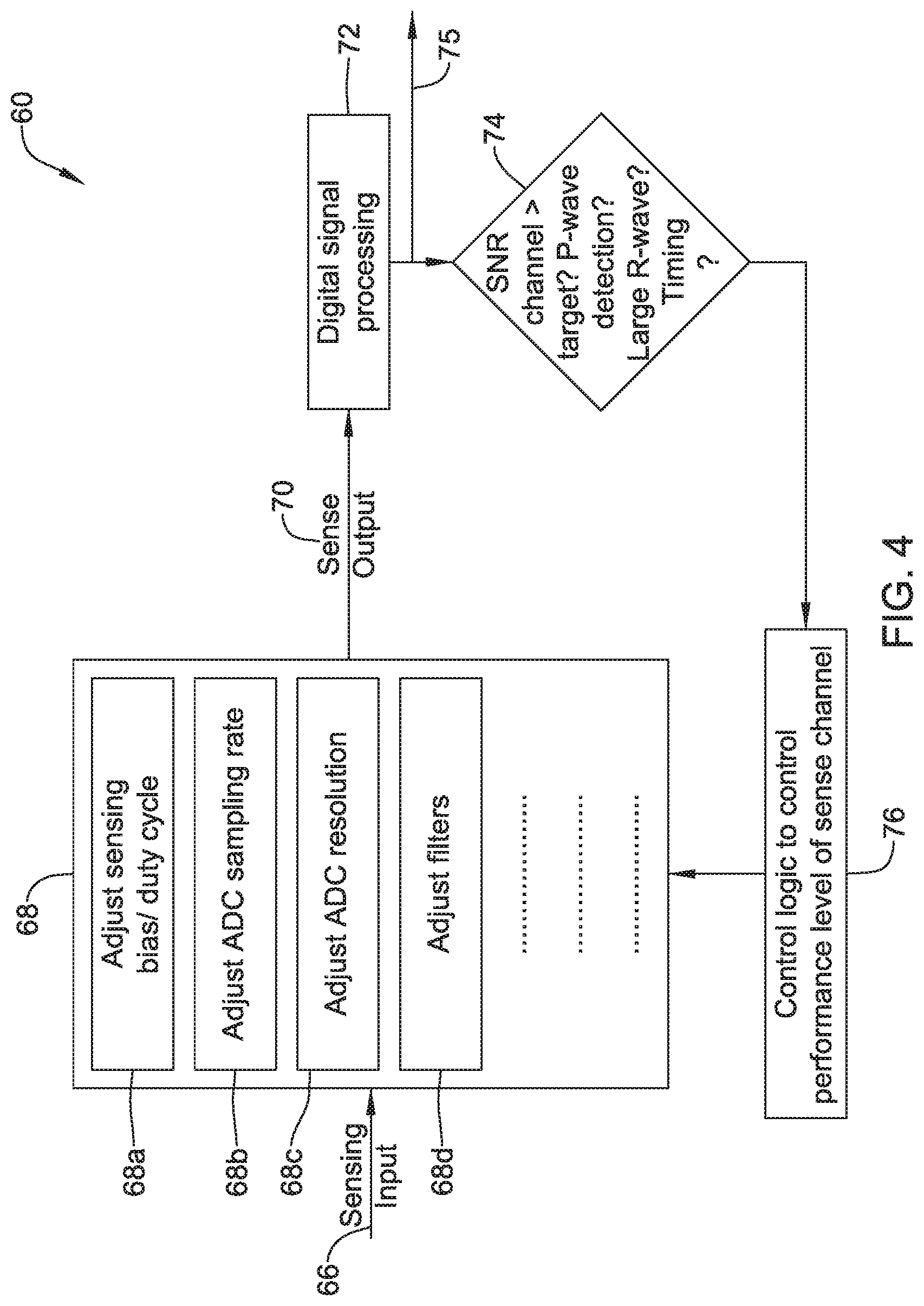
Alternatively or additionally to any of the embodiments above, the controller may be configured to determine a measure of a signal-to-noise ratio (SNR) of the sense channel output signal, and to adjust the performance level of the sense channel based at least in part on the measure of the signal-to-noise ratio (SNR) of the sense channel output signal.
Alternatively or additionally to any of the embodiments above, the performance level of the sense channel may be adjusted by adjusting a noise floor of a sense amplifier of the sense channel.
Alternatively or additionally to any of the embodiments above, the performance level of the sense channel may be adjusted by adjusting a resolution of the sense channel and/or a supply voltage of a sense amplifier of the sense channel.
Alternatively or additionally to any of the embodiments above, the performance level of the sense channel may be adjusted by adjusting a sample rate of the sense channel.
Alternatively or additionally to any of the embodiments above, the sense channel may include a sense amplifier, and the performance level of the sense channel may be adjusted by adjusting a bias of the sense amplifier.
Alternatively or additionally to any of the embodiments above, the sense channel is activated and deactivated at a duty cycle, and the performance level of the sense channel may be adjusted by adjusting the duty cycle of the sense channel.
Alternatively or additionally to any of the embodiments above, the sense channel samples the sensor output signal at a sample rate, and the performance level of the sense channel may be adjusted by adjusting the sample rate of the sense channel.
Alternatively or additionally to any of the embodiments above, the sense channel includes an analog-to-digital (A/D) converter with an adjustable resolution, and the performance level of the sense channel may be adjusted by adjusting the resolution of the A/D converter.
Alternatively or additionally to any of the embodiments above, the IMD is configured to sense and process two or more different cardiac signals, and the controller may be configured to adjust the performance level of the sense channel based at least in part on which of the two or more different cardiac signals is to be sensed and processed. In some cases, the two or more different cardiac signals include an R-wave and a P-Wave, and the controller may be configured to adjust the performance level of the sense channel to achieve more performance and more power consumption when the P-Wave is to be sensed and processed, and to adjust the performance level of the sense channel to achieve less performance and less power consumption when the R-Wave is to be sensed and processed.
Alternatively or additionally to any of the embodiments above, the controller may be configured to automatically and dynamically adjust the performance level of the sense channel.
Alternatively or additionally to any of the embodiments above, the IMD may be a leadless cardiac pacemaker (LCP).
Alternatively or additionally to any of the embodiments above, the IMD may be an insertable cardiac monitor (ICM).
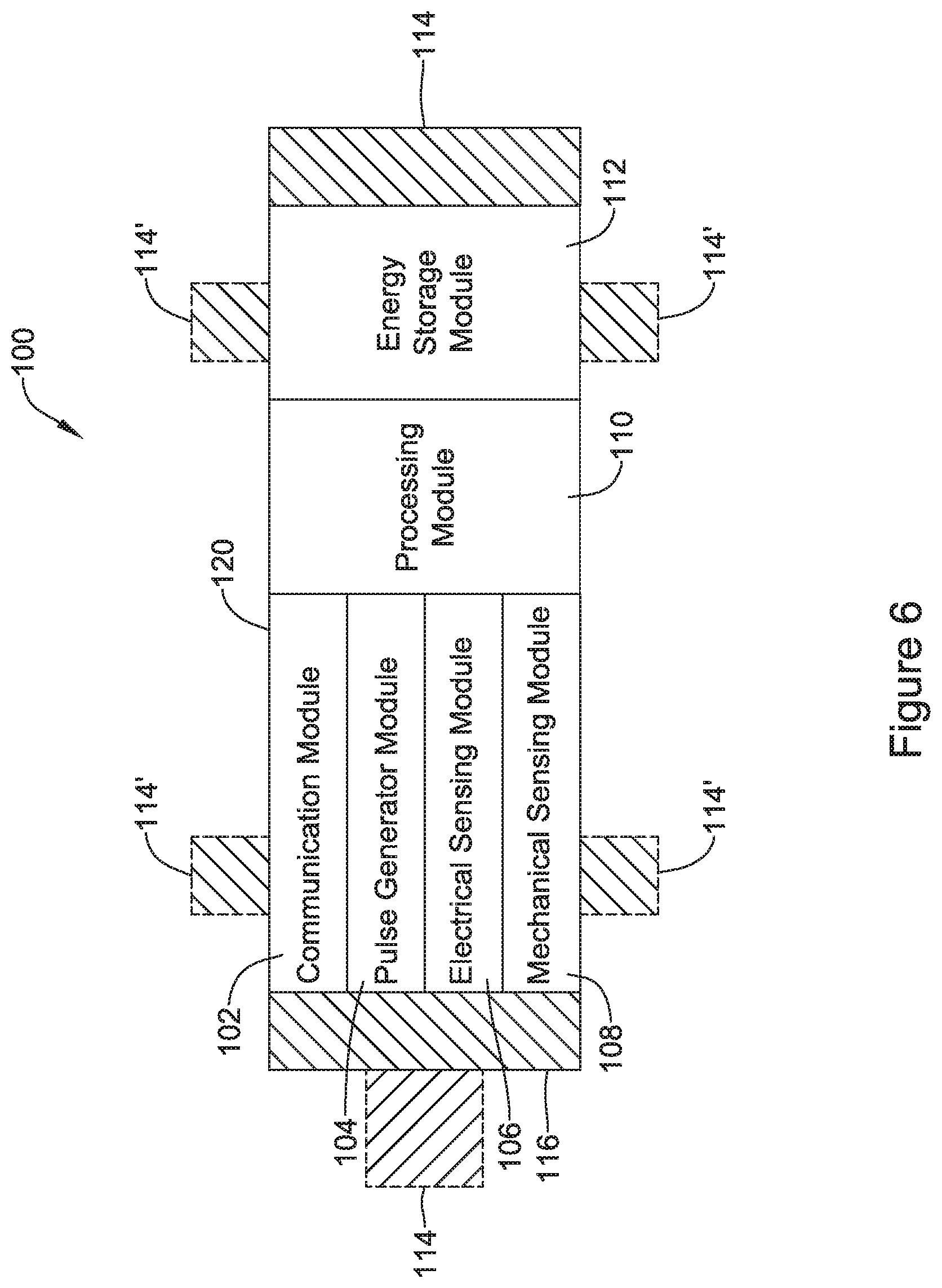
In another example, a leadless cardiac pacemaker (LCP) configured for implantation into a patient's heart may be configured to sense electrical cardiac activity and to deliver pacing pulses to the patient's heart. The LCP may include a housing, a first electrode that is secured relative to the housing and a second electrode that is secured relative to the housing and is spaced from the first electrode. A controller may be disposed within the housing and may be operably coupled to the first electrode and the second electrode such that the controller is capable of receiving, via the first electrode and the second electrode, electrical cardiac signals of the heart. A sensor may be disposed within the housing and may be configured to sense an indication of cardiac activity and provide a sensor output signal. A sense channel may be configured to receive the sensor output signal from the sensor, process the sensor output signal and to output a sense channel output signal. In some cases, the sense channel may have an adjustable performance level, wherein for a higher performance level the sense channel consumes more power and for a lower performance level the sense channel consumes less power. The controller may be configured to receive the sense channel output signal and to adjust the performance level of the sense channel to achieve more performance and more power consumption when a higher degree of performance is desired and to achieve less performance and less power consumption when a high degree of performance is not desired.
Alternatively or additionally to any of the embodiments above, the LCP may be configured to sense and process two or more different cardiac signals, and the controller may be configured to adjust the performance level of the sense channel based at least in part on which of the two or more different cardiac signals is to be sensed and processed.
Alternatively or additionally to any of the embodiments above, the sensor may include an electrical signal sensor that senses an electric signal between the first electrode and the second electrode.
Alternatively or additionally to any of the embodiments above, the sensor may include one or more of an accelerometer, a pressure sensor, a gyroscope, and a magnetic sensor.
In another example, a method of monitoring a patient's heart using an implantable medical device that is configured for implantation proximate the patient's heart and that includes a sensor configured to sense an indication of cardiac activity, a dynamically adjustable sense channel configured to process a signal from the sensor, and a controller operably coupled to the dynamically adjustable sense channel. The illustrative method includes sensing an indication of cardiac activity using the sensor, the sensor outputting a signal to the dynamically adjustable sense channel. The dynamically adjustable sense channel is operated at a performance level to process the signal from the sensor and output the processed signal to the controller. The processed signal may then be analyzed for an indication of signal quality and a determination may be made as to whether the indication of signal quality is acceptable. The performance level of the dynamically adjustable sense channel may be adjusted upward if the indication of signal quality is not acceptable. In some cases, the performance level of the dynamically adjustable sense channel may be adjusted downward to a lower performance level if the indication of signal quality exceeds a threshold to help reduce power consumption. The illustrative method may further include repeating the sensing, operating, analyzing, determining and adjusting steps until the indication of signal quality is determined to be acceptable.
The above summary of some illustrative embodiments is not intended to describe each disclosed embodiment or every implementation of the present disclosure. The Figures, and Detailed Description, which follow, more particularly exemplify some of these embodiments.
BRIEF DESCRIPTION OF THE DRAWINGS
The disclosure may be more completely understood in consideration of the following detailed description in connection with the accompanying drawings, in which:
FIG. 1 is a schematic block diagram of an implantable medical device (IMD) in accordance with an example of the disclosure;
FIG. 2 is a schematic block diagram of a leadless cardiac pacemaker (LCP) in accordance with an example of the disclosure;
FIG. 3 is a schematic diagram of an illustrative logic flow that may be used in the IMD of FIG. 1 and/or the LCP of FIG. 2;
FIG. 4 is a schematic diagram of an illustrative logic flow that may be used in the IMD of FIG. 1 and/or the LCP of FIG. 2;
FIG. 5 is a schematic illustration of a cardiac signal, indicating example time ranges for activating a sense channel in order to reduce power consumption;
FIG. 6 is a schematic block diagram of an illustrative LCP in accordance with an example of the disclosure;
FIG. 7 is a schematic block diagram of another illustrative medical device that may be used in conjunction with the LCP of FIG. 6;
FIG. 8 is a schematic diagram of an exemplary medical system that includes multiple LCPs and/or other devices in communication with one another;
FIG. 9 is a schematic diagram of a system including an LCP and another medical device, in accordance with an example of the disclosure;
FIG. 10 is a side view of an illustrative implantable leadless cardiac device; and
FIG. 11 is a flow diagram of an illustrative method for monitoring a patient's heart using the IMD of FIG. 1 and/or the LCP of FIG. 2.
While the disclosure is amenable to various modifications and alternative forms, specifics thereof have been shown by way of example in the drawings and will be described in detail. It should be understood, however, that the intention is not to limit the disclosure to the particular embodiments described. On the contrary, the intention is to cover all modifications, equivalents, and alternatives falling within the spirit and scope of the disclosure.
DETAILED DESCRIPTION
For the following defined terms, these definitions shall be applied, unless a different definition is given in the claims or elsewhere in this specification.
All numeric values are herein assumed to be modified by the term "about," whether or not explicitly indicated. The term "about" generally refers to a range of numbers that one of skill in the art would consider equivalent to the recited value (i.e., having the same function or result). In many instances, the terms "about" may include numbers that are rounded to the nearest significant figure.
The recitation of numerical ranges by endpoints includes all numbers within that range (e.g. 1 to 5 includes 1, 1.5, 2, 2.75, 3, 3.80, 4, and 5).
As used in this specification and the appended claims, the singular forms "a", "an", and "the" include plural referents unless the content clearly dictates otherwise. As used in this specification and the appended claims, the term "or" is generally employed in its sense including "and/or" unless the content clearly dictates otherwise.
It is noted that references in the specification to "an embodiment", "some embodiments", "other embodiments", etc., indicate that the embodiment described may include one or more particular features, structures, and/or characteristics. However, such recitations do not necessarily mean that all embodiments include the particular features, structures, and/or characteristics. Additionally, when particular features, structures, and/or characteristics are described in connection with one embodiment, it should be understood that such features, structures, and/or characteristics may also be used connection with other embodiments whether or not explicitly described unless clearly stated to the contrary.
The following detailed description should be read with reference to the drawings in which similar structures in different drawings are numbered the same. The drawings, which are not necessarily to scale, depict illustrative embodiments and are not intended to limit the scope of the disclosure.
FIG. 1 is a schematic view of an implantable medical device (IMD) 10. In some cases, the IMD 10 may represent an insertable cardiac monitor (ICM). In some cases, the IMD 10 may represent a cardiac pacemaker such as a leadless cardiac pacemaker (LCP). These are just examples.
Cardiac pacemakers provide electrical stimulation to heart tissue to cause the heart to contract and thus pump blood through the vascular system. Conventional pacemakers may include an electrical lead that extends from a pulse generator implanted subcutaneously or sub-muscularly to an electrode positioned adjacent the inside or outside wall of the cardiac chamber. As an alternative to conventional pacemakers, self-contained or leadless cardiac pacemakers (LCP) have been proposed. Leadless cardiac pacemakers (LCP) are small capsules that may, for example, be fixed to an intracardiac implant site in a cardiac chamber. In some cases, the small capsule may include bipolar pacing/sensing electrodes, a power source (e.g. a battery), and associated electrical circuitry for controlling the pacing/sensing electrodes, and thus may provide electrical stimulation to heart tissue and/or sense a physiological condition. The capsule may be delivered to the heart using a delivery device which may be advanced through a femoral vein, into the inferior vena cava, into the right atrium, through the tricuspid valve, and into the right ventricle. Accordingly, it may be desirable to provide delivery devices which facilitate advancement through the vasculature.
Referring specifically to FIG. 1, and in some instances, the IMD 10 includes a housing 12 and a sensor 14 that may be configured to provide a sensor output signal. In some cases, the sensor 14 may be an electrical signal sensor that senses an electric signal between, for example, two sensor electrodes. In some instances, the sensor 14 may be one or more of an accelerometer, a pressure sensor, a gyroscope and a magnetic sensor. These are just examples. In some cases, a sense channel 16 may be configured to receive the sensor output signal from the sensor 14, process the sensor output signal and output a sense channel output signal. It is contemplated that the sensor output signal may be processed by an analog circuit (e.g. sense amplifier), a digital circuit (e.g. Analog-to-Digital Converter) and/or digital processor, or both. In some cases, the sense channel 16 may have an adjustable performance level, wherein a higher performance level the sense channel 16 consumes more power than a lower performance level.
A controller 18 may be configured to receive the sense channel output signal from the sense channel 16. In some case, the controller 18 may be configured to adjust the performance level of the sense channel 16 to achieve more performance (and thus more power consumption) when a higher degree of performance is desired, and to achieve less performance (and less power consumption) when a high degree of performance is not desired. In some cases, the controller 18 may be configured to adjust the performance level of the sense channel 16 in accordance with one or more received signals or other indications of the patient's posture and/or activity level. For example, if the patient is sleeping, the sense channel 16 may be operated at a lower performance level as their cardiac cycle may be expected to vary less, for example. As another example, if the patient is relatively active, the sense channel 16 may be operated at a higher performance level as their cardiac cycle may be expected to vary more.
In some cases, the controller 18 may be configured to dynamically adjust the performance level of the sense channel 16. In some cases, for example, the controller 18 may be configured to determine a measure of a signal-to-noise ratio (SNR) of the sense channel output signal, and adjust the performance level of the sense channel 16 based at least in part on the measure of the signal-to-noise ratio (SNR) of the sense channel output signal. In another example, the IMD 10 may be configured to sense and process two or more different cardiac signals, and the controller 18 may be configured to adjust the performance level of the sense channel 16 based at least in part on which of the two or more different cardiac signals is to be sensed and processed. For example, the two or more different cardiac signals may include an R-wave and a P-Wave, and the controller 18 may be configured to adjust the performance level of the sense channel 16 to achieve more performance and more power consumption when the P-Wave is to be sensed and processed, and to adjust the performance level of the sense channel 16 to achieve less performance and less power consumption when the R-Wave is to be sensed and processed.
In some cases, the performance level of the sense channel 16 may be increased by increasing a noise floor and/or a bias of a sense amplifier (not explicitly shown) of the sense channel 16. In some cases, the performance level of the sense channel may be increased by increasing a sample rate of the sense channel 16. If increased sensitivity is desired, the controller 18 may increase the sample rate of the sense channel 16. In some cases, if increased sensitivity is desired, the controller 18 may increase the supply voltage to the sense channel 16. If power conservation considerations outweigh a need for sensitivity, the controller 18 may decrease the sample rate of the sense channel 16. In some cases, the sense channel 16 may be activated and deactivated at a duty cycle, and the performance level of the sense channel 16 may be adjusted by adjusting the duty cycle of the sense channel 16. In some cases, a duty cycle may correspond to a single cardiac cycle. In some cases, a duty cycle may correspond to several consecutive cardiac cycles. In some instances, for example, the duty cycle may pertain to turning off the sense channel 16 during a refractory period. As another example, in some cases the duty cycle may include turning the sense channel 16 on during a particular cardiac cycle and then turning the sense channel 16 off during a subsequent cardiac cycle. These are just examples. In some cases, the sense channel 16 may include an analog-to-digital (A/D) converter with an adjustable resolution, and the performance level of the sense channel 16 may be adjusted by adjusting the resolution and/or sample rate of the A/D converter.
A power supply 20 may provide power to the sensor 14, sense channel 16 and/or controller 18. The power supply 20 may include a capacitor, a battery and/or any other suitable power storage device. In some cases, the power supply 20 may be a non-rechargeable lithium-based battery. These are just examples. In most cases, the power supply will have a limited power capacity, which limits the effective lifetime of the corresponding implanted medical device. To extend the effective lifetime of the implanted medical device, there is a desire to reduce battery consumption while still providing effective monitoring and/or delivery of therapy to the patient.
FIG. 2 is a schematic view of a leadless cardiac pacemaker (LCP) 22 that is configured for implantation into a patient's heart. The LCP 22 may be configured to sense electrical cardiac activity and to deliver pacing pulses to the patient's heart when appropriate. In some cases, the LCP 22 may include a housing 24, a first electrode 26 that is secured relative to the housing 24, and a second electrode 28 that is secured relative to the housing 24 and that is spaced from the first electrode 26. A controller 30 may be disposed within the housing 24 and may be operably coupled to the first electrode 26 and to the second electrode 28 such that the controller 30 is capable of receiving, via the first electrode 26 and the second electrode 28, electrical cardiac signals of the patient's heart. In some cases, a sensor 32 may be disposed within the housing 24 and may be configured to sense an indication of cardiac activity and/or another parameter relative to the patient and to provide a sensor output signal. A sense channel 34 may be configured to receive the sensor output signal from the sensor 32 and to process (analog and/or digital) the sensor output signal in order to output a sense channel output signal. In some cases, the sense channel 34 may have an adjustable performance level, wherein for a higher performance level the sense channel 34 consumes more power and for a lower performance level the sense channel 34 consumes less power.
The controller 30 may be configured to receive the sense channel output signal and adjust the performance level of the sense channel 34 to achieve more performance and more power consumption when a higher degree of performance is desired and to achieve less performance and less power consumption when a high degree of performance is not desired. The controller 30, sense channel 34 and/or sensor 32 may be operably powered by a power supply 36.
In some cases, the sensor 32 may be an electrical signal sensor that senses an electric signal between the first electrode 26 and the second electrode 28. In some instances, the sensor 32 may be one or more of an accelerometer, a pressure sensor, a gyroscope and a magnetic sensor. These are just some example sensors.
In some cases, the controller 30 may be configured to dynamically adjust the performance level of the sense channel 34. In some cases, for example, the controller 30 may be configured to determine a measure of a signal-to-noise ratio (SNR) of the sense channel output signal, and adjust the performance level of the sense channel 34 based at least in part on the measure of the signal-to-noise ratio (SNR) of the sense channel output signal. In another example, the LCP 22 may be configured to sense and process two or more different cardiac signals, and the controller 30 may be configured to adjust the performance level of the sense channel 34 based at least in part on which of the two or more different cardiac signals is to be sensed and processed. For example, the two or more different cardiac signals may include an R-wave and a P-Wave, and the controller 30 may be configured to adjust the performance level of the sense channel 34 to achieve more performance and more power consumption when the P-Wave is to be sensed and processed, and to adjust the performance level of the sense channel 34 to achieve less performance and less power consumption when the R-Wave is to be sensed and processed.
In some cases, the performance level of the sense channel 34 may be increased by increasing a noise floor and/or a bias of a sense amplifier (not explicitly shown) of the sense channel 34. In some cases, the performance level of the sense channel 34 may be increased by increasing a sample rate of the sense channel 34. If increased sensitivity is desired, the controller 30 may increase the sample rate of the sense channel 34. If power conservation considerations outweigh a need for sensitivity, the controller 30 may decrease the sample rate of the sense channel 34. In some cases, the sense channel 34 may be activated and deactivated at a duty cycle, and the performance level of the sense channel 34 may be adjusted by adjusting the duty cycle of the sense channel 34. In some cases, the sense channel 34 may include an analog-to-digital (A/D) converter with an adjustable resolution, and the performance level of the sense channel 34 may be adjusted by adjusting the resolution and/or sample rate of the A/D converter. These are just examples.
FIG. 3 is a schematic diagram of an illustrative logic flow 40 that may be used in controlling the sense channel 16 (FIG. 1) and/or the sense channel 34 (FIG. 2). In some cases, the logic flow 40 may be considered as including a sense signal flow block 42 and a power control feedback block 44. In some instances, a sense input 46 may enter the logic flow 40, such as a signal from the sensor 14 (FIG. 1) and/or the sensor 32 (FIG. 2) and pass through the sense channel 48. In the example shown, the sense channel 48 may function to amplify the sense input 46, and provide a sense output signal 50 to a digital control logic block 52. The digital control logic block 52, when provided, may include an Analog-to-Digital Converter (ADC) and/or other digital processing circuitry. In the example shown in FIG. 3, a sense channel output signal 55 exits the digital control logic block 52 and may be used by the controller 18 (FIG. 1) and/or controller 30 (FIG. 2 to control one or more functions of the IMD 10 (FIG. 1) and/or LCP (FIG. 2).
In the example shown in FIG. 3, the sense channel output signal 55 is also provided to the power control feedback block 44. The power control feedback block 44 may be part of the controller 18 (FIG. 1), the controller 30 (FIG. 2), or a separate control block. In FIG. 3, the sense channel output signal 55 is provided to a signal to noise (SNR) decision block 54 of the power control feedback block 44. The SNR decision block 54 may determine a SNR value for the sense channel output signal 55, and may compare the SNR value to a threshold, standard or baseline. In the example shown, the control block 56 may adjust the performance level of the sense channel 48 depending on whether the SNR value is above or below a SNR value. In some cases, the control block 56 may adjust the performance level of the sense channel 48 upward to provide an increased signal to noise ratio (SNR Value) if the desired signal (e.g. P-wave) in the sense input 46 is small relative to existing noise, or perhaps to adjust the performance level of the sense channel 48 downward to reduce the signal to noise ratio (SNR value) if the desired signal (e.g. R-wave) in the sense input 46 is relatively large relative to existing noise. This is just one example.
FIG. 4 is a schematic diagram of an illustrative logic flow 60 that may be used in controlling the sense channel 16 (FIG. 1) and/or the sense channel 34 (FIG. 2). In some instances, a sense input 66 may enter the logic flow 60, such as a signal from the sensor 14 (FIG. 1) and/or the sensor 32 (FIG. 2) and pass through the sense channel 68. In some cases, the sense channel 68 may function to amplify the sense input 66, and provide a sense output signal 70 to a digital signal processing block 72. The digital signal processing block 72, when provided, may include an Analog-to-Digital Converter (ADC) and/or other digital processing circuitry. In the example shown in FIG. 4, a sense channel output signal 75 exits the digital signal processing block 72 and may be used by the controller 18 (FIG. 1) and/or controller 30 (FIG. 2) to control one or more functions of the IMD 10 (FIG. 1) and/or LCP (FIG. 2).
In the example shown in FIG. 4, the sense channel output signal 75 is also provided to a signal to noise (SNR) decision block 74, where a SNR value for a desired signal in the sense channel output signal 75 is estimated or determined. A control block 76 may then adjust the performance level of the sense channel 68 to achieve a desired SNR value in the sense channel output signal 75. In some cases, the SNR value may be directly measured.
Rather than directly measuring the SNR value, it is contemplated that the SNR decision block 74 may simply identify whether the IMD or LCP is currently attempting to sense a smaller signal (e.g. P-wave) that may have a relatively lower signal to noise ratio (SNR), or if the IMD or LCP is currently attempting to sense a larger signal (e.g. an R-wave) that may have a relatively higher signal to noise ratio (SNR). This may be reported to the control block 76. If the IMD or LCP is currently attempting to sense a smaller signal, the control block 76 may automatically increase the performance level of the sense channel 68 at the expense of power consumption, and if the IMD or LCP is currently attempting to sense a larger signal, the control block 76 may decrease the performance level of the sense channel 68 to reduce power consumption. In some cases, the SNR decision block 74 may confirm that the resulting SNR value is sufficient.
Control block 76 may be part of a feedback path to adjust the performance level of the sense channel 68. In some cases, the control block 76 may adjusted the sense channel 68 to, for example, provide an increased signal to noise ratio (SNR value) if the sense input 66 is small relative to existing noise, or perhaps to allow a decreased signal to noise ratio (SNR value) if the sense input 66 is relatively robust relative to existing noise. In some cases, the decision block 74 may monitor the sense channel output signal 75 when a desired signal is not expected at the sense input 66 to help identify the existing noise level.
In some cases, the sense channel 68 may have an adjustable performance level. For example, a bias and/or gain of a sense amplifier of the sense channel 68 may be adjusted as shown at block 68a to change the performance level of the sense channel 68. Increasing the gain may amplifier a desired signal relative to the existing noise. In another example, a sampling rate and/or resolution (number of bits) of an ADC may be adjusted as shown at blocks 68b and 68c, to change the performance level of the sense channel 68. In another example, one or more filters (Low pass, high pass, band pass) of the sense channel 68 may be activated/deactivated and/or one or more poles of one or more filters may be adjusted, as shown at block 68d, to help filter the noise and thus change the performance level of the sense channel 68. These are just examples.
In some cases, a sense channel or portions thereof may be operated in accordance with an expected timing within, for example, a cardiac cycle. For example, if a sensor operably coupled to a sense channel is configured to sense a P-wave, the sense channel may be configured to turn itself on or to increase its resolution, sensitivity or gain shortly before the next P-wave is expected. To illustrate, FIG. 5 provides a cardiac signal trace 80 including a first QRS complex 82 and a second QRS complex 84 and a timing signal 86. In the example shown, an expected PT time (e.g. an expected time from P-wave to T-wave) may be utilized. This is labeled as delta T0 on the timing signal 86, and may be on the order of 300 milliseconds. In some cases, the sense channel may be activated or placed in a higher performance mode during the period delta T0, and deactivated or placed in a lower performance mode outside of the period delta T0.
In some case, the sense channel may be turned off just before the T-wave (such as about 0 to 50 milliseconds after the previous R-wave), and then may be turned on a time delta T1 before the P-wave. In some cases, P-wave timing may be predicted using a timing fiducial from a previous cardiac cycle, and a time period denoted as delta T2 may be subtracted from an R-R interval (time between a first R-wave and a second R-wave). As another option, a dynamic PT time may be used, based upon the QT interval, which is based on the heart rate. These are just examples of adjusting the performance level of a sense channel based on when a desired signal is expected to be present.
FIG. 6 depicts an illustrative leadless cardiac pacemaker (LCP) that may be implanted into a patient and may operate to deliver appropriate therapy to the heart, such as to deliver anti-tachycardia pacing (ATP) therapy, cardiac resynchronization therapy (CRT), bradycardia therapy, and/or the like. The LCP shown in FIG. 6 may include the features described herein for adjusting the performance level of a sense channel. As can be seen in FIG. 6, the LCP 100 may be a compact device with all components housed within the or directly on a housing 120. In some cases, the LCP 100 may be considered as being an example of the IMD 10 (FIG. 1) and/or the LCP 22 (FIG. 2). In the example shown in FIG. 6, the LCP 100 may include a communication module 102, a pulse generator module 104, an electrical sensing module 106, a mechanical sensing module 108, a processing module 110, a battery 112, and an electrode arrangement 114. The LCP 100 may include more or less modules, depending on the application.
The communication module 102 may be configured to communicate with devices such as sensors, other medical devices such as an SICD, and/or the like, that are located externally to the LCP 100. Such devices may be located either external or internal to the patient's body. Irrespective of the location, external devices (i.e. external to the LCP 100 but not necessarily external to the patient's body) can communicate with the LCP 100 via communication module 102 to accomplish one or more desired functions. For example, the LCP 100 may communicate information, such as sensed electrical signals, data, instructions, messages, R-wave detection markers, etc., to an external medical device (e.g. SICD and/or programmer) through the communication module 102. The external medical device may use the communicated signals, data, instructions, messages, R-wave detection markers, etc., to perform various functions, such as determining occurrences of arrhythmias, delivering electrical stimulation therapy, storing received data, and/or performing any other suitable function. The LCP 100 may additionally receive information such as signals, data, instructions and/or messages from the external medical device through the communication module 102, and the LCP 100 may use the received signals, data, instructions and/or messages to perform various functions, such as determining occurrences of arrhythmias, delivering electrical stimulation therapy, storing received data, and/or performing any other suitable function. The communication module 102 may be configured to use one or more methods for communicating with external devices. For example, the communication module 102 may communicate via radiofrequency (RF) signals, inductive coupling, optical signals, acoustic signals, conducted communication signals, and/or any other signals suitable for communication.
In the example shown in FIG. 6, the pulse generator module 104 may be electrically connected to the electrodes 114. In some examples, the LCP 100 may additionally include electrodes 114'. In such examples, the pulse generator 104 may also be electrically connected to the electrodes 114'. The pulse generator module 104 may be configured to generate electrical stimulation signals. For example, the pulse generator module 104 may generate and deliver electrical stimulation signals by using energy stored in the battery 112 within the LCP 100 and deliver the generated electrical stimulation signals via the electrodes 114 and/or 114'. Alternatively, or additionally, the pulse generator 104 may include one or more capacitors, and the pulse generator 104 may charge the one or more capacitors by drawing energy from the battery 112. The pulse generator 104 may then use the energy of the one or more capacitors to deliver the generated electrical stimulation signals via the electrodes 114 and/or 114'. In at least some examples, the pulse generator 104 of the LCP 100 may include switching circuitry to selectively connect one or more of the electrodes 114 and/or 114' to the pulse generator 104 in order to select which of the electrodes 114/114' (and/or other electrodes) the pulse generator 104 delivers the electrical stimulation therapy. The pulse generator module 104 may generate and deliver electrical stimulation signals with particular features or in particular sequences in order to provide one or multiple of a number of different stimulation therapies. For example, the pulse generator module 104 may be configured to generate electrical stimulation signals to provide electrical stimulation therapy to combat bradycardia, tachycardia, cardiac synchronization, bradycardia arrhythmias, tachycardia arrhythmias, fibrillation arrhythmias, cardiac synchronization arrhythmias and/or to produce any other suitable electrical stimulation therapy. Some more common electrical stimulation therapies include anti-tachycardia pacing (ATP) therapy, cardiac resynchronization therapy (CRT), and cardioversion/defibrillation therapy. In some cases, the pulse generator 104 may provide a controllable pulse energy. In some cases, the pulse generator 104 may allow the controller to control the pulse voltage, pulse width, pulse shape or morphology, and/or any other suitable pulse characteristic.
In some examples, the LCP 100 may include an electrical sensing module 106, and in some cases, a mechanical sensing module 108. The electrical sensing module 106 may be configured to sense the cardiac electrical activity of the heart. For example, the electrical sensing module 106 may be connected to the electrodes 114/114', and the electrical sensing module 106 may be configured to receive cardiac electrical signals conducted through the electrodes 114/114'. The cardiac electrical signals may represent local information from the chamber in which the LCP 100 is implanted. For instance, if the LCP 100 is implanted within a ventricle of the heart (e.g. RV, LV), cardiac electrical signals sensed by the LCP 100 through the electrodes 114/114' may represent ventricular cardiac electrical signals. In some cases, the LCP 100 may be configured to detect cardiac electrical signals from other chambers (e.g. far field), such as the P-wave from the atrium.
The mechanical sensing module 108 may include one or more sensors, such as an accelerometer, a pressure sensor, a heart sound sensor, a blood-oxygen sensor, a chemical sensor, a temperature sensor, a flow sensor and/or any other suitable sensors that are configured to measure one or more mechanical/chemical parameters of the patient. Both the electrical sensing module 106 and the mechanical sensing module 108 may be connected to a processing module 110, which may provide signals representative of the sensed mechanical parameters. Although described with respect to FIG. 6 as separate sensing modules, in some cases, the electrical sensing module 206 and the mechanical sensing module 208 may be combined into a single sensing module, as desired.
The electrodes 114/114' can be secured relative to the housing 120 but exposed to the tissue and/or blood surrounding the LCP 100. In some cases, the electrodes 114 may be generally disposed on either end of the LCP 100 and may be in electrical communication with one or more of the modules 102, 104, 106, 108, and 110. The electrodes 114/114' may be supported by the housing 120, although in some examples, the electrodes 114/114' may be connected to the housing 120 through short connecting wires such that the electrodes 114/114' are not directly secured relative to the housing 120. In examples where the LCP 100 includes one or more electrodes 114', the electrodes 114' may in some cases be disposed on the sides of the LCP 100, which may increase the number of electrodes by which the LCP 100 may sense cardiac electrical activity, deliver electrical stimulation and/or communicate with an external medical device. The electrodes 114/114' can be made up of one or more biocompatible conductive materials such as various metals or alloys that are known to be safe for implantation within a human body. In some instances, the electrodes 114/114' connected to the LCP 100 may have an insulative portion that electrically isolates the electrodes 114/114' from adjacent electrodes, the housing 120, and/or other parts of the LCP 100. In some cases, one or more of the electrodes 114/114' may be provided on a tail (not shown) that extends away from the housing 120.
The processing module 110 can be configured to control the operation of the LCP 100. For example, the processing module 110 may be configured to receive electrical signals from the electrical sensing module 106 and/or the mechanical sensing module 108. Based on the received signals, the processing module 110 may determine, for example, abnormalities in the operation of the heart H. Based on any determined abnormalities, the processing module 110 may control the pulse generator module 104 to generate and deliver electrical stimulation in accordance with one or more therapies to treat the determined abnormalities. The processing module 110 may further receive information from the communication module 102. In some examples, the processing module 110 may use such received information to help determine whether an abnormality is occurring, determine a type of abnormality, and/or to take particular action in response to the information. The processing module 110 may additionally control the communication module 102 to send/receive information to/from other devices.
In some examples, the processing module 110 may include a pre-programmed chip, such as a very-large-scale integration (VLSI) chip and/or an application specific integrated circuit (ASIC). In such embodiments, the chip may be pre-programmed with control logic in order to control the operation of the LCP 100. By using a pre-programmed chip, the processing module 110 may use less power than other programmable circuits (e.g. general purpose programmable microprocessors) while still being able to maintain basic functionality, thereby potentially increasing the battery life of the LCP 100. In other examples, the processing module 110 may include a programmable microprocessor. Such a programmable microprocessor may allow a user to modify the control logic of the LCP 100 even after implantation, thereby allowing for greater flexibility of the LCP 100 than when using a pre-programmed ASIC. In some examples, the processing module 110 may further include a memory, and the processing module 110 may store information on and read information from the memory. In other examples, the LCP 100 may include a separate memory (not shown) that is in communication with the processing module 110, such that the processing module 110 may read and write information to and from the separate memory.
The battery 112 may provide power to the LCP 100 for its operations. In some examples, the battery 112 may be a non-rechargeable lithium-based battery. In other examples, a non-rechargeable battery may be made from other suitable materials, as desired. Because the LCP 100 is an implantable device, access to the LCP 100 may be limited after implantation. Accordingly, it is desirable to have sufficient battery capacity to deliver therapy over a period of treatment such as days, weeks, months, years or even decades. In some instances, the battery 112 may a rechargeable battery, which may help increase the useable lifespan of the LCP 100. In still other examples, the battery 112 may be some other type of power source, as desired.
To implant the LCP 100 inside a patient's body, an operator (e.g., a physician, clinician, etc.), may fix the LCP 100 to the cardiac tissue of the patient's heart. To facilitate fixation, the LCP 100 may include one or more anchors 116. The anchor 116 may include any one of a number of fixation or anchoring mechanisms. For example, the anchor 116 may include one or more pins, staples, threads, screws, helix, tines, and/or the like. In some examples, although not shown, the anchor 116 may include threads on its external surface that may run along at least a partial length of the anchor 116. The threads may provide friction between the cardiac tissue and the anchor to help fix the anchor 116 within the cardiac tissue. In other examples, the anchor 116 may include other structures such as barbs, spikes, or the like to facilitate engagement with the surrounding cardiac tissue.
FIG. 7 depicts an example of another or second medical device (MD) 200, which may be used in conjunction with the LCP 100 (FIG. 6) in order to detect and/or treat cardiac abnormalities. In some cases, the MD 200 may be considered as an example of the IMD 10 (FIG. 1) and/or the LCP 22 (FIG. 2). In the example shown, the MD 200 may include a communication module 202, a pulse generator module 204, an electrical sensing module 206, a mechanical sensing module 208, a processing module 210, and a battery 218. Each of these modules may be similar to the modules 102, 104, 106, 108, and 110 of LCP 100. Additionally, the battery 218 may be similar to the battery 112 of the LCP 100. In some examples, however, the MD 200 may have a larger volume within the housing 220. In such examples, the MD 200 may include a larger battery and/or a larger processing module 210 capable of handling more complex operations than the processing module 110 of the LCP 100.
While it is contemplated that the MD 200 may be another leadless device such as shown in FIG. 6, in some instances the MD 200 may include leads such as leads 212. The leads 212 may include electrical wires that conduct electrical signals between the electrodes 214 and one or more modules located within the housing 220. In some cases, the leads 212 may be connected to and extend away from the housing 220 of the MD 200. In some examples, the leads 212 are implanted on, within, or adjacent to a heart of a patient. The leads 212 may contain one or more electrodes 214 positioned at various locations on the leads 212, and in some cases at various distances from the housing 220. Some leads 212 may only include a single electrode 214, while other leads 212 may include multiple electrodes 214. Generally, the electrodes 214 are positioned on the leads 212 such that when the leads 212 are implanted within the patient, one or more of the electrodes 214 are positioned to perform a desired function. In some cases, the one or more of the electrodes 214 may be in contact with the patient's cardiac tissue. In some cases, the one or more of the electrodes 214 may be positioned subcutaneously and outside of the patient's heart. In some cases, the electrodes 214 may conduct intrinsically generated electrical signals to the leads 212, e.g. signals representative of intrinsic cardiac electrical activity. The leads 212 may, in turn, conduct the received electrical signals to one or more of the modules 202, 204, 206, and 208 of the MD 200. In some cases, the MD 200 may generate electrical stimulation signals, and the leads 212 may conduct the generated electrical stimulation signals to the electrodes 214. The electrodes 214 may then conduct the electrical signals and delivery the signals to the patient's heart (either directly or indirectly).
The mechanical sensing module 208, as with the mechanical sensing module 108, may contain or be electrically connected to one or more sensors, such as accelerometers, acoustic sensors, blood pressure sensors, heart sound sensors, blood-oxygen sensors, and/or other sensors which are configured to measure one or more mechanical/chemical parameters of the heart and/or patient. In some examples, one or more of the sensors may be located on the leads 212, but this is not required. In some examples, one or more of the sensors may be located in the housing 220.
While not required, in some examples, the MD 200 may be an implantable medical device. In such examples, the housing 220 of the MD 200 may be implanted in, for example, a transthoracic region of the patient. The housing 220 may generally include any of a number of known materials that are safe for implantation in a human body and may, when implanted, hermetically seal the various components of the MD 200 from fluids and tissues of the patient's body.
In some cases, the MD 200 may be an implantable cardiac pacemaker (ICP). In this example, the MD 200 may have one or more leads, for example the leads 212, which are implanted on or within the patient's heart. The one or more leads 212 may include one or more electrodes 214 that are in contact with cardiac tissue and/or blood of the patient's heart. The MD 200 may be configured to sense intrinsically generated cardiac electrical signals and determine, for example, one or more cardiac arrhythmias based on analysis of the sensed signals. The MD 200 may be configured to deliver CRT, ATP therapy, bradycardia therapy, and/or other therapy types via the leads 212 implanted within the heart. In some examples, the MD 200 may additionally be configured provide defibrillation therapy.
In some instances, the MD 200 may be an implantable cardioverter-defibrillator (ICD). In such examples, the MD 200 may include one or more leads implanted within a patient's heart. The MD 200 may also be configured to sense cardiac electrical signals, determine occurrences of tachyarrhythmias based on the sensed signals, and may be configured to deliver defibrillation therapy in response to determining an occurrence of a tachyarrhythmia. In other examples, the MD 200 may be a subcutaneous implantable cardioverter-defibrillator (S-ICD). In examples where the MD 200 is an S-ICD, one of the leads 212 may be a subcutaneously implanted lead. In at least some examples where the MD 200 is an S-ICD, the MD 200 may include only a single lead which is implanted subcutaneously, but this is not required. In some instances, the lead(s) may have one or more electrodes that are placed subcutaneously and outside of the chest cavity. In other examples, the lead(s) may have one or more electrodes that are placed inside of the chest cavity, such as just interior of the sternum but outside of the heart H.
In some examples, the MD 200 may not be an implantable medical device. Rather, the MD 200 may be a device external to the patient's body, and may include skin-electrodes that are placed on a patient's body. In such examples, the MD 200 may be able to sense surface electrical signals (e.g. cardiac electrical signals that are generated by the heart or electrical signals generated by a device implanted within a patient's body and conducted through the body to the skin). In such examples, the MD 200 may be configured to deliver various types of electrical stimulation therapy, including, for example, defibrillation therapy.
FIG. 8 illustrates an example of a medical device system and a communication pathway through which multiple medical devices 302, 304, 306, and/or 310 may communicate. In the example shown, the medical device system 300 may include LCPs 302 and 304, external medical device 306, and other sensors/devices 310. The external device 306 may be any of the devices described previously with respect to the MD 200. Other sensors/devices 310 may also be any of the devices described previously with respect to the MD 200. In some instances, other sensors/devices 310 may include a sensor, such as an accelerometer, an acoustic sensor, a blood pressure sensor, or the like. In some cases, other sensors/devices 310 may include an external programmer device that may be used to program one or more devices of the system 300.
Various devices of the system 300 may communicate via communication pathway 308. For example, the LCPs 302 and/or 304 may sense intrinsic cardiac electrical signals and may communicate such signals to one or more other devices 302/304, 306, and 310 of the system 300 via communication pathway 308. In one example, one or more of the devices 302/304 may receive such signals and, based on the received signals, determine an occurrence of an arrhythmia. In some cases, the device or devices 302/304 may communicate such determinations to one or more other devices 306 and 310 of the system 300. In some cases, one or more of the devices 302/304, 306, and 310 of the system 300 may take action based on the communicated determination of an arrhythmia, such as by delivering a suitable electrical stimulation to the heart of the patient. It is contemplated that the communication pathway 308 may communicate using RF signals, inductive coupling, optical signals, acoustic signals, or any other signals suitable for communication. Additionally, in at least some examples, device communication pathway 308 may include multiple signal types. For instance, other sensors/device 310 may communicate with the external device 306 using a first signal type (e.g. RF communication) but communicate with the LCPs 302/304 using a second signal type (e.g. conducted communication). Further, in some examples, communication between devices may be limited. For instance, as described above, in some examples, the LCPs 302/304 may communicate with the external device 306 only through other sensors/devices 310, where the LCPs 302/304 send signals to other sensors/devices 310, and other sensors/devices 310 relay the received signals to the external device 306.
In some cases, the communication pathway 308 may include conducted communication. Accordingly, devices of the system 300 may have components that allow for such conducted communication. For instance, the devices of system 300 may be configured to transmit conducted communication signals (e.g. current and/or voltage pulses) into the patient's body via one or more electrodes of a transmitting device, and may receive the conducted communication signals (e.g. pulses) via one or more electrodes of a receiving device. The patient's body may "conduct" the conducted communication signals (e.g. pulses) from the one or more electrodes of the transmitting device to the electrodes of the receiving device in the system 300. In such examples, the delivered conducted communication signals (e.g. pulses) may differ from pacing or other therapy signals. For example, the devices of the system 300 may deliver electrical communication pulses at an amplitude/pulse width that is sub-capture threshold to the heart. Although, in some cases, the amplitude/pulse width of the delivered electrical communication pulses may be above the capture threshold of the heart, but may be delivered during a blanking period of the heart (e.g. refractory period) and/or may be incorporated in or modulated onto a pacing pulse, if desired.
Delivered electrical communication pulses may be modulated in any suitable manner to encode communicated information. In some cases, the communication pulses may be pulse width modulated or amplitude modulated. Alternatively, or in addition, the time between pulses may be modulated to encode desired information. In some cases, conducted communication pulses may be voltage pulses, current pulses, biphasic voltage pulses, biphasic current pulses, or any other suitable electrical pulse as desired.
FIG. 9 shows an illustrative medical device system. In FIG. 9, an LCP 402 is shown fixed to the interior of the left ventricle of the heart 410, and a pulse generator 406 is shown coupled to a lead 412 having one or more electrodes 408a-408c. In some cases, the pulse generator 406 may be part of a subcutaneous implantable cardioverter-defibrillator (S-ICD), and the one or more electrodes 408a-408c may be positioned subcutaneously. In some cases, the one or more electrodes 408a-408c may be placed inside of the chest cavity but outside of the heart, such as just interior of the sternum.
In some cases, the LCP 402 may communicate with the subcutaneous implantable cardioverter-defibrillator (S-ICD). In some cases, the lead 412 and/or pulse generator 406 may include an accelerometer 414 that may, for example, be configured to sense vibrations that may be indicative of heart sounds.
In some cases, the LCP 402 may be in the right ventricle, right atrium, left ventricle or left atrium of the heart, as desired. In some cases, more than one LCP 402 may be implanted. For example, one LCP may be implanted in the right ventricle and another may be implanted in the right atrium. In another example, one LCP may be implanted in the right ventricle and another may be implanted in the left ventricle. In yet another example, one LCP may be implanted in each of the chambers of the heart.
FIG. 10 is a side view of an illustrative implantable leadless cardiac pacemaker (LCP) 610. The LCP 610 may be similar in form and function to the LCP 100 described above. The LCP 610 may include any of the modules and/or structural features described above with respect to the LCP 100 described above. The LCP 610 may include a shell or housing 612 having a proximal end 614 and a distal end 616. The illustrative LCP 610 includes a first electrode 620 secured relative to the housing 612 and positioned adjacent to the distal end 616 of the housing 612 and a second electrode 622 secured relative to the housing 612 and positioned adjacent to the proximal end 614 of the housing 612. In some cases, the housing 612 may include a conductive material and may be insulated along a portion of its length. A section along the proximal end 614 may be free of insulation so as to define the second electrode 622. The electrodes 620, 622 may be sensing and/or pacing electrodes to provide electro-therapy and/or sensing capabilities. The first electrode 620 may be capable of being positioned against or may otherwise contact the cardiac tissue of the heart while the second electrode 622 may be spaced away from the first electrode 620. The first and/or second electrodes 620, 622 may be exposed to the environment outside the housing 612 (e.g. to blood and/or tissue).
In some cases, the LCP 610 may include a pulse generator (e.g., electrical circuitry) and a power source (e.g., a battery) within the housing 612 to provide electrical signals to the electrodes 620, 622 to control the pacing/sensing electrodes 620, 622. While not explicitly shown, the LCP 610 may also include, a communications module, an electrical sensing module, a mechanical sensing module, and/or a processing module, and the associated circuitry, similar in form and function to the modules 102, 106, 108, 110 described above. The various modules and electrical circuitry may be disposed within the housing 612. Electrical connections between the pulse generator and the electrodes 620, 622 may allow electrical stimulation to heart tissue and/or sense a physiological condition.
In the example shown, the LCP 610 includes a fixation mechanism 624 proximate the distal end 616 of the housing 612. The fixation mechanism 624 is configured to attach the LCP 610 to a wall of the heart H, or otherwise anchor the LCP 610 to the anatomy of the patient. In some instances, the fixation mechanism 624 may include one or more, or a plurality of hooks or tines 626 anchored into the cardiac tissue of the heart H to attach the LCP 610 to a tissue wall. In other instances, the fixation mechanism 624 may include one or more, or a plurality of passive tines, configured to entangle with trabeculae within the chamber of the heart H and/or a helical fixation anchor configured to be screwed into a tissue wall to anchor the LCP 610 to the heart H. These are just examples.
The LCP 610 may further include a docking member 630 proximate the proximal end 614 of the housing 612. The docking member 630 may be configured to facilitate delivery and/or retrieval of the LCP 610. For example, the docking member 630 may extend from the proximal end 614 of the housing 612 along a longitudinal axis of the housing 612. The docking member 630 may include a head portion 632 and a neck portion 634 extending between the housing 612 and the head portion 632. The head portion 632 may be an enlarged portion relative to the neck portion 634. For example, the head portion 632 may have a radial dimension from the longitudinal axis of the LCP 610 that is greater than a radial dimension of the neck portion 634 from the longitudinal axis of the LCP 610. In some cases, the docking member 630 may further include a tether retention structure 636 extending from or recessed within the head portion 632. The tether retention structure 636 may define an opening 638 configured to receive a tether or other anchoring mechanism therethrough. While the retention structure 636 is shown as having a generally "U-shaped" configuration, the retention structure 636 may take any shape that provides an enclosed perimeter surrounding the opening 638 such that a tether may be securably and releasably passed (e.g. looped) through the opening 638. In some cases, the retention structure 636 may extend though the head portion 632, along the neck portion 634, and to or into the proximal end 614 of the housing 612. The docking member 630 may be configured to facilitate delivery of the LCP 610 to the intracardiac site and/or retrieval of the LCP 610 from the intracardiac site. While this describes one example docking member 630, it is contemplated that the docking member 630, when provided, can have any suitable configuration.
It is contemplated that the LCP 610 may include one or more pressure sensors 640 coupled to or formed within the housing 612 such that the pressure sensor(s) is exposed to the environment outside the housing 612 to measure blood pressure within the heart. For example, if the LCP 610 is placed in the left ventricle, the pressure sensor(s) 640 may measure the pressure within the left ventricle. If the LCP 610 is placed in another portion of the heart (such as one of the atriums or the right ventricle), the pressures sensor(s) may measure the pressure within that portion of the heart. The pressure sensor(s) 640 may include a MEMS device, such as a MEMS device with a pressure diaphragm and piezoresistors on the diaphragm, a piezoelectric sensor, a capacitor-Micro-machined Ultrasonic Transducer (cMUT), a condenser, a micro-monometer, or any other suitable sensor adapted for measuring cardiac pressure. The pressures sensor(s) 640 may be part of a mechanical sensing module described herein. It is contemplated that the pressure measurements obtained from the pressures sensor(s) 640 may be used to generate a pressure curve over cardiac cycles. The pressure readings may be taken in combination with impedance measurements (e.g. the impedance between electrodes 620 and 622) to generate a pressure-impedance loop for one or more cardiac cycles as will be described in more detail below. The impedance may be a surrogate for chamber volume, and thus the pressure-impedance loop may be representative for a pressure-volume loop for the heart H.
In some embodiments, the LCP 610 may be configured to measure impedance between the electrodes 620, 622. More generally, the impedance may be measured between other electrode pairs, such as the additional electrodes 114' described above. In some cases, the impedance may be measure between two spaced LCP's, such as two LCP's implanted within the same chamber (e.g. LV) of the heart H, or two LCP's implanted in different chambers of the heart H (e.g. RV and LV). The processing module of the LCP 610 and/or external support devices may derive a measure of cardiac volume from intracardiac impedance measurements made between the electrodes 620, 622 (or other electrodes). Primarily due to the difference in the resistivity of blood and the resistivity of the cardiac tissue of the heart H, the impedance measurement may vary during a cardiac cycle as the volume of blood (and thus the volume of the chamber) surrounding the LCP changes. In some cases, the measure of cardiac volume may be a relative measure, rather than an actual measure. In some cases, the intracardiac impedance may be correlated to an actual measure of cardiac volume via a calibration process, sometimes performed during implantation of the LCP(s). During the calibration process, the actual cardiac volume may be determined using fluoroscopy or the like, and the measured impedance may be correlated to the actual cardiac volume.
In some cases, the LCP 610 may be provided with energy delivery circuitry operatively coupled to the first electrode 620 and the second electrode 622 for causing a current to flow between the first electrode 620 and the second electrode 622 in order to determine the impedance between the two electrodes 620, 622 (or other electrode pair). It is contemplated that the energy delivery circuitry may also be configured to deliver pacing pulses via the first and/or second electrodes 620, 622. The LCP 610 may further include detection circuitry operatively coupled to the first electrode 620 and the second electrode 622 for detecting an electrical signal received between the first electrode 620 and the second electrode 622. In some instances, the detection circuitry may be configured to detect cardiac signals received between the first electrode 620 and the second electrode 622.
When the energy delivery circuitry delivers a current between the first electrode 620 and the second electrode 622, the detection circuitry may measure a resulting voltage between the first electrode 620 and the second electrode 622 (or between a third and fourth electrode separate from the first electrode 620 and the second electrode 622, not shown) to determine the impedance. When the energy delivery circuitry delivers a voltage between the first electrode 620 and the second electrode 622, the detection circuitry may measure a resulting current between the first electrode 620 and the second electrode 622 (or between a third and fourth electrode separate from the first electrode 620 and the second electrode 622) to determine the impedance.
FIG. 11 is a flow diagram showing an illustrative method 700 of monitoring a patient's heart using an implantable medical device (such as, but not limited to, the IMD 10 of FIG. 1, the LCP of FIG. 2, the LCP of FIG. 6, the LCP of FIG. 10) that is configured for implantation proximate the patient's heart and that includes a sensor configured to sense an indication of cardiac activity and a dynamically adjustable sense channel configured to process a signal from the sensor. The implantable medical device may further include a controller to dynamically adjust the performance level of the sense channel. As generally seen at block 702, an indication of cardiac activity may be sensed using the sensor. The sensor outputs a signal to the dynamically adjustable sense channel. The dynamically adjustable sense channel may be operated at a performance level to process the signal from the sensor and output the processed signal to the controller, as indicated at block 704. In some cases, and as seen at block 706, the processed signal may be analyzed for an indication of signal quality and a determination may be made as to whether the indication of signal quality is acceptable, as indicated at block 708. In some cases, and as seen at block 710, the performance level of the dynamically adjustable sense channel may be adjusted upward if the indication of signal quality is not acceptable. In some cases, the performance level of the dynamically adjustable sense channel may be adjusted downward to a lower performance level if the indication of signal quality exceeds a threshold in order to help reduce power consumption of the implantable medical device. In some cases, these steps may be repeated until the indication of signal quality is determined to be acceptable, as indicated by a dashed control line 712.
It should be understood that this disclosure is, in many respects, only illustrative. Changes may be made in details, particularly in matters of shape, size, and arrangement of steps without exceeding the scope of the disclosure. This may include, to the extent that it is appropriate, the use of any of the features of one example embodiment being used in other embodiments. The disclosure's scope is, of course, defined in the language in which the appended claims are expressed.
* * * * *
D00000
D00001
D00002
D00003
D00004
D00005
D00006
D00007
D00008
D00009
D00010
D00011
XML
uspto.report is an independent third-party trademark research tool that is not affiliated, endorsed, or sponsored by the United States Patent and Trademark Office (USPTO) or any other governmental organization. The information provided by uspto.report is based on publicly available data at the time of writing and is intended for informational purposes only.
While we strive to provide accurate and up-to-date information, we do not guarantee the accuracy, completeness, reliability, or suitability of the information displayed on this site. The use of this site is at your own risk. Any reliance you place on such information is therefore strictly at your own risk.
All official trademark data, including owner information, should be verified by visiting the official USPTO website at www.uspto.gov. This site is not intended to replace professional legal advice and should not be used as a substitute for consulting with a legal professional who is knowledgeable about trademark law.