Pressure sensor with improved strain gauge
Huo , et al. Feb
U.S. patent number 10,557,770 [Application Number 15/704,797] was granted by the patent office on 2020-02-11 for pressure sensor with improved strain gauge. This patent grant is currently assigned to Sensata Technologies, Inc.. The grantee listed for this patent is Sensata Technologies, Inc.. Invention is credited to Shihong Huo, Neil S. Petrarca, Eric A. Wolf.


| United States Patent | 10,557,770 |
| Huo , et al. | February 11, 2020 |
Pressure sensor with improved strain gauge
Abstract
An apparatus senses a pressure of a fluid from a fluid medium. The apparatus has a port body with a peripheral wall surrounding an interior channel. The interior channel extends between a diaphragm on the port body and an opening for receiving the fluid. A strain gauge is disposed on the port body. The strain gauge has two or more resistors connected between input/output pads and ground pads. The resistors are spaced substantially equidistant from the ground pad to reduce mobile ion migration.
| Inventors: | Huo; Shihong (Bedford, MA), Wolf; Eric A. (Norwood, MA), Petrarca; Neil S. (Warwick, RI) | ||||||||||
|---|---|---|---|---|---|---|---|---|---|---|---|
| Applicant: |
|
||||||||||
| Assignee: | Sensata Technologies, Inc.
(Attleboro, MA) |
||||||||||
| Family ID: | 64013383 | ||||||||||
| Appl. No.: | 15/704,797 | ||||||||||
| Filed: | September 14, 2017 |
Prior Publication Data
| Document Identifier | Publication Date | |
|---|---|---|
| US 20190078953 A1 | Mar 14, 2019 | |
| Current U.S. Class: | 1/1 |
| Current CPC Class: | G01L 9/0055 (20130101); G01L 9/06 (20130101) |
| Current International Class: | G01L 9/00 (20060101) |
| Field of Search: | ;73/727 |
References Cited [Referenced By]
U.S. Patent Documents
| 4072058 | February 1978 | Whitehead, Jr. |
| 4131088 | December 1978 | Reddy |
| 4287772 | September 1981 | Mounteer et al. |
| 4347745 | September 1982 | Singh |
| 4400681 | August 1983 | Brown et al. |
| 4462018 | July 1984 | Yang |
| 4771427 | September 1988 | Tulpule et al. |
| 4817362 | April 1989 | Archer |
| 4825876 | May 1989 | Beard |
| 4888662 | December 1989 | Bishop |
| 4903164 | February 1990 | Bishop et al. |
| 4967605 | November 1990 | Okada |
| 5060108 | October 1991 | Baker et al. |
| 5101659 | April 1992 | Takeuchi |
| 5101665 | April 1992 | Mizuno |
| 5144843 | September 1992 | Tamura et al. |
| 5173766 | December 1992 | Long et al. |
| 5181417 | January 1993 | Nishida et al. |
| 5184107 | February 1993 | Maurer |
| 5184515 | February 1993 | Terry et al. |
| 5209121 | May 1993 | Hafner |
| 5222397 | June 1993 | Kodama |
| 5231301 | July 1993 | Peterson et al. |
| 5284107 | February 1994 | Milne et al. |
| 5295307 | March 1994 | Archer |
| 5331857 | July 1994 | Levine et al. |
| 5349865 | September 1994 | Kavli et al. |
| 5425371 | June 1995 | Mischenko |
| 5448444 | September 1995 | Provenzano et al. |
| 5457988 | October 1995 | Delatorre |
| 5587535 | December 1996 | Sasaki et al. |
| 5625151 | April 1997 | Yamaguchi |
| 5629486 | May 1997 | Viduya et al. |
| 5665921 | September 1997 | Gerst et al. |
| 5741975 | April 1998 | Vaughn, II et al. |
| 5802912 | September 1998 | Pitzer et al. |
| 5866822 | February 1999 | Willig |
| 5869766 | February 1999 | Cucci et al. |
| 6033544 | March 2000 | Demers et al. |
| 6050145 | April 2000 | Olson et al. |
| 6070883 | June 2000 | Marto |
| 6119524 | September 2000 | Kobold |
| 6204594 | March 2001 | Ingham |
| 6351998 | March 2002 | Hohnstadt et al. |
| 6389903 | May 2002 | Oba et al. |
| 6411038 | June 2002 | Murai et al. |
| 6439058 | August 2002 | Aratani et al. |
| 6453747 | September 2002 | Weise et al. |
| 6487911 | December 2002 | Frackelton et al. |
| 6536287 | March 2003 | Beekhuizen et al. |
| 6539787 | April 2003 | Murai et al. |
| 6568276 | May 2003 | Ciminelli |
| 6700174 | March 2004 | Miu et al. |
| 6715357 | April 2004 | Ishiguro et al. |
| RE38557 | July 2004 | Englund et al. |
| 6763724 | July 2004 | DiPaola et al. |
| 6876943 | April 2005 | Wegerich |
| 6945118 | September 2005 | Maitland et al. |
| 6952042 | October 2005 | Stratton et al. |
| 6973837 | December 2005 | Barnett |
| 7021147 | January 2006 | Subramanian et al. |
| 7032456 | April 2006 | Amin |
| 7114396 | October 2006 | Oda et al. |
| 7197937 | April 2007 | Amore et al. |
| 7207214 | April 2007 | Wlodarczyk |
| 7302855 | December 2007 | Oda |
| 7316164 | January 2008 | Toyoda et al. |
| 7383737 | June 2008 | Lin et al. |
| 7412894 | August 2008 | Ueyanagi et al. |
| 7518234 | April 2009 | Okojie |
| 7555957 | July 2009 | Toyoda |
| 7570065 | August 2009 | Harish et al. |
| 7578194 | August 2009 | Hadjiloucas et al. |
| 7726197 | June 2010 | Selvan et al. |
| 7739922 | June 2010 | Inamori |
| 7775119 | August 2010 | Suminto et al. |
| 8024978 | September 2011 | Khemet et al. |
| 8056752 | November 2011 | Carnevali |
| 8104357 | January 2012 | Schlitzkus et al. |
| 8129624 | March 2012 | Willner et al. |
| 8156816 | April 2012 | Willner et al. |
| 8164007 | April 2012 | Speldrich et al. |
| 8215176 | July 2012 | Ding et al. |
| 8250909 | August 2012 | Kern et al. |
| 8258799 | September 2012 | Bernstein |
| 8297115 | October 2012 | Borgers et al. |
| 8429956 | April 2013 | Borgers et al. |
| 8516897 | August 2013 | Jones et al. |
| 8627559 | January 2014 | Suminto et al. |
| 8671767 | March 2014 | Kaiser et al. |
| 8950247 | February 2015 | Borgers et al. |
| 8984949 | March 2015 | Staiger et al. |
| 9003897 | April 2015 | Wade et al. |
| 9046436 | June 2015 | Schlitzkus et al. |
| 9063033 | June 2015 | Mayer et al. |
| 9689767 | June 2017 | Van Der Wiel |
| 2001/0015402 | August 2001 | Murai et al. |
| 2001/0039837 | November 2001 | Tanizawa et al. |
| 2002/0029639 | March 2002 | Wagner et al. |
| 2002/0073533 | June 2002 | Park |
| 2002/0100948 | August 2002 | Yoshihara et al. |
| 2003/0033884 | February 2003 | Beekhuizen et al. |
| 2003/0150275 | August 2003 | Wagner et al. |
| 2004/0007073 | January 2004 | Weise |
| 2004/0007074 | January 2004 | DiPaola et al. |
| 2004/0007075 | January 2004 | Ishiguro et al. |
| 2004/0015282 | January 2004 | Babala et al. |
| 2004/0020300 | February 2004 | Boehler et al. |
| 2004/0132900 | July 2004 | Sachdev et al. |
| 2004/0146719 | July 2004 | Baney et al. |
| 2004/0147140 | July 2004 | Fan et al. |
| 2004/0200286 | October 2004 | Mast |
| 2004/0255682 | December 2004 | Petrova |
| 2005/0011273 | January 2005 | Sasaki et al. |
| 2005/0103111 | May 2005 | Imai et al. |
| 2005/0252300 | November 2005 | Miller |
| 2006/0000289 | January 2006 | Jonsson |
| 2006/0042393 | March 2006 | Kaneko et al. |
| 2006/0042394 | March 2006 | Kosh et al. |
| 2006/0042395 | March 2006 | Lepine et al. |
| 2006/0053894 | March 2006 | Kunda et al. |
| 2006/0090566 | May 2006 | Oda |
| 2006/0123887 | June 2006 | Dordet |
| 2006/0214202 | September 2006 | Zorich et al. |
| 2006/0278012 | December 2006 | Fujimoto et al. |
| 2007/0113667 | May 2007 | Stratton |
| 2007/0148788 | June 2007 | Hsieh et al. |
| 2007/0154631 | July 2007 | Sachdev et al. |
| 2007/0202628 | August 2007 | Wuertz |
| 2007/0205776 | September 2007 | Harish et al. |
| 2008/0148860 | June 2008 | Murakami et al. |
| 2008/0222884 | September 2008 | Bradley et al. |
| 2008/0262584 | October 2008 | Bottomley et al. |
| 2009/0071260 | March 2009 | Speldrich |
| 2009/0075529 | March 2009 | Johnston et al. |
| 2009/0282926 | November 2009 | Hauer et al. |
| 2009/0315864 | December 2009 | Silverbrook et al. |
| 2009/0320576 | December 2009 | Borgers et al. |
| 2010/0052578 | March 2010 | Kim |
| 2010/0192696 | August 2010 | Schlitzkus et al. |
| 2010/0219487 | September 2010 | Donis |
| 2010/0239109 | September 2010 | Lutz et al. |
| 2010/0267291 | October 2010 | Chabineau-Lovgren et al. |
| 2010/0281994 | November 2010 | Brown et al. |
| 2011/0088480 | April 2011 | Koehler et al. |
| 2011/0108322 | May 2011 | Kaiser |
| 2011/0153277 | June 2011 | Morath |
| 2011/0290030 | December 2011 | Willner et al. |
| 2011/0320158 | December 2011 | Steckenreiter et al. |
| 2012/0067130 | March 2012 | Kaiser et al. |
| 2012/0227477 | September 2012 | Borgers et al. |
| 2013/0052936 | February 2013 | Jordan |
| 2013/0073189 | March 2013 | Korenaga et al. |
| 2013/0192379 | August 2013 | Petrarca |
| 2013/0248024 | September 2013 | Dunn et al. |
| 2013/0264664 | October 2013 | Nimura et al. |
| 2013/0336511 | December 2013 | Underbrink et al. |
| 2014/0130585 | May 2014 | Borgers et al. |
| 2014/0130586 | May 2014 | Zwollo et al. |
| 2014/0137654 | May 2014 | Zwijze |
| 2014/0144206 | May 2014 | Uehlin et al. |
| 2014/0219713 | August 2014 | Balsells et al. |
| 2014/0260648 | September 2014 | Aoyama et al. |
| 2014/0338448 | November 2014 | Ashino |
| 2015/0135853 | May 2015 | McNeal et al. |
| 2015/0377729 | December 2015 | Hio et al. |
| 2016/0025581 | January 2016 | Kazama |
| 2016/0133762 | May 2016 | Blasco Claret |
| 2016/0265998 | September 2016 | Lavado et al. |
| 2016/0282205 | September 2016 | Huo et al. |
| 103454032 | Dec 2013 | CN | |||
| 4234289 | Nov 1993 | DE | |||
| 4407212 | Aug 1995 | DE | |||
| 102004048367 | Apr 2006 | DE | |||
| 085584 | Aug 1983 | EP | |||
| 1074827 | Feb 2001 | EP | |||
| 1211497 | Jun 2002 | EP | |||
| 1560012 | Aug 2005 | EP | |||
| 1826543 | Aug 2007 | EP | |||
| 2390641 | Nov 2011 | EP | |||
| 2620757 | Jul 2013 | EP | |||
| 2637008 | Sep 2013 | EP | |||
| 2848908 | Mar 2015 | EP | |||
| 3315936 | May 2018 | EP | |||
| 2791430 | Sep 2000 | FR | |||
| 2066590 | Jul 1981 | GB | |||
| 406037334 | Feb 1994 | JP | |||
| 2010256187 | Nov 2010 | JP | |||
| WO-0242720 | May 2002 | WO | |||
| WO-2003100371 | Dec 2003 | WO | |||
| WO-2006102460 | Sep 2006 | WO | |||
| WO-2011155054 | Dec 2011 | WO | |||
| WO-2013083320 | Jun 2013 | WO | |||
| WO-2013110045 | Jul 2013 | WO | |||
| WO-2014132730 | Sep 2014 | WO | |||
Attorney, Agent or Firm: Burns & Levinson LLP Maraia; Joseph M. McGrath; Daniel J.
Claims
What is claimed is:
1. An apparatus for sensing a pressure of a fluid from a fluid medium comprising: a port body having a peripheral wall surrounding an interior channel for receiving the fluid from the fluid medium, the interior channel extending between the fluid medium and a diaphragm on the port body; a strain gauge affixed to the port body by a glass substrate, the strain gauge comprising: a first resistor electrically connected between a first input/output (I/O) pad and a ground pad; a second resistor electrically connected between a second I/O pad and the ground pad; a third resistor electrically connected between a third I/O pad and the ground pad; and a fourth resistor electrically connected between a fourth I/O pad and the ground pad; four current sources, each current source providing a uniform, constant current to one of the I/O pads; a first output electrically connected between the first I/O pad and the second I/O pad for measuring voltage; and a second output electrically connected between the third I/O pad and the fourth I/O pad for measuring voltage, wherein: each resistor is spaced substantially equidistant from the ground pad to urge uniform mobile ion accumulation across the resistors; and when the diaphragm experiences pressure from the fluid: the second resistor and the third resistor experience a tension force; and the first resistor and fourth resistor experience a compression force.
2. An apparatus for sensing a pressure of a fluid from a fluid medium comprising: a port body having a peripheral wall surrounding an interior channel, the interior channel extending between a diaphragm on the port body and an opening for receiving the fluid; and a strain gauge disposed on the port body comprising: a first resistor electrically connected between a first input/output (I/O) pad and a ground pad; a second resistor electrically connected between a second I/O pad and the ground pad; a third resistor electrically connected between a third I/O pad and the ground pad; and a fourth resistor electrically connected between a fourth I/O pad and the ground pad, wherein each resistor is substantially equidistant from the ground pad to reduce mobile ion migration.
3. The apparatus of claim 2 wherein a uniform input is applied through each resistor simultaneously.
4. The apparatus of claim 2 wherein: the first I/O pad and the second I/O pad are disposed on a first side of the ground pad; and the third I/O pad and the fourth I/O pad are disposed on a second side of the ground pad.
5. The apparatus of claim 4 wherein the I/O pads and the ground pad are arranged in a parallel row.
6. The apparatus of claim 2 wherein the resistors are piezoresistive elements.
7. The apparatus of claim 2 wherein: the first resistor and the fourth resistor are positioned adjacent to the peripheral wall and the second resistor and the third resistor are positioned adjacent to the diaphragm, such that fluid in the interior channel causes the first and fourth resistors to experience compression while the second and third resistors experience tension.
8. The apparatus of claim 2 wherein the first resistor and the fourth resistor are symmetrical to the second resistor and the third resistor about a lateral axis passing through the I/O pads.
9. The apparatus of claim 2 wherein: the ground pad is elongated along a longitudinal axis; and the first resistor and the second resistor are symmetrical about the longitudinal axis to the fourth resistor and the third resistor.
10. An apparatus for sensing a pressure of a fluid from a fluid medium comprising: a strain gauge comprising: a first resistor electrically connected between a first input/output (I/O) pad and a ground pad; a second resistor electrically connected between a second I/O pad and the ground pad; a first output electrically connected between the first I/O pad and the second I/O pad; a third resistor forming a first resistor pair with the second resistor; and a fourth resistor forming a second resistor pair with the first resistor, wherein, wherein: the first and second resistors are spaced from the ground pad to urge uniform mobile ion accumulation across the first and second resistors: and the first resistor pair and the second resistor pair are symmetrical about a lateral axis.
11. The apparatus of claim 10 wherein the resistors are spaced substantially equidistant from the ground pad.
12. The apparatus of claim 10 wherein a constant current is applied through the first resistor and the second resistor, the constant current being uniform.
13. The apparatus of claim 12 wherein: the constant current is applied to the first resistor via the first I/O pad; the constant current is applied to the second resistor via the second I/O pad; and the output measures a change in voltage between the first I/O pad and the second I/O pad.
14. The apparatus of claim 13 wherein the first I/O pad, the second I/O pad, and the ground pad are aligned along a lateral axis, the first resistor and the second resistor being symmetrical about the lateral axis.
15. The apparatus of claim 10 wherein a constant voltage is applied through the first resistor and the second resistor, the constant voltage being uniform.
16. The apparatus of claim 10 wherein the strain gauge further comprises: the third resistor electrically connected between a third I/O pad and the ground pad; the fourth resistor electrically connected between a fourth I/O pad and the ground pad; and a second output electrically connected between the third I/O pad and the fourth I/O pad.
17. The apparatus of claim 16 further comprising a port body defining an interior channel for receiving the fluid from the fluid medium, wherein the strain gauge is disposed on the port body.
18. The apparatus of claim 17 wherein the port body is conductive and grounded.
19. The apparatus of claim 17 wherein: the first resistor and the fourth resistor are positioned adjacent to a peripheral wall of the port body surrounding the interior channel such that fluid in the channel causes the first resistor and the fourth resistor to experience a compression force; and the second resistor and the third resistor are positioned adjacent to a diaphragm within the port body, the diaphragm being exposed to the interior channel, such that fluid in the channel causes the second resistor and the third resistor to experience a tension force.
20. The apparatus of claim 16 wherein: the first resistor and the second resistor form a first resistor pair; the third resistor and the fourth resistor form a second resistor pair; and the first resistor pair and the second resistor pair are symmetrical about a longitudinal axis.
Description
FIELD OF THE INVENTION
The subject disclosure relates to pressure sensing devices and more particularly to pressure sensors with improved strain gauge performance.
BACKGROUND OF THE INVENTION
Microfused silicon strain gauge (MSG) pressure sensors are widely used throughout a number of industries. In the automotive industry, MSGs are used for applications ranging from brake, transmission, and fuel pressure sensors, to occupant weight force sensing. Such pressure sensors typically include silicon strain gauge elements which are glass-bonded to a stainless steel diaphragm of a steel port body. Wheatstone bridge, or other strain gauge configurations are sometimes employed to yield a linear voltage output which is directly proportional to the applied pressure on the steel diaphragm by calibration.
However, inaccuracies tend to occur in typical MSGs in a number of ways. For example, when temperature rises above 110 Celsius, chemical decomposition tends to occur within the glass generating mobile ions. When the steel port body is grounded, the mobile ions will flock towards the resistors closest to the supply voltage. Disparate ion accumulate across the resistors can lead to sensor signal drift. Further, designs which seek to avoid sensor signal drift can result in sensors with reduced sensitivity, unfavorable resistor or pad positioning, or other inaccuracies.
SUMMARY OF THE INVENTION
In light of the needs described above, in at least one aspect, there is a need for a cost effective pressure sensor and strain gauge which can accurately sense pressure without significant signal drift.
In at least one aspect the subject technology relates to an apparatus for sensing a pressure of a fluid from a fluid medium. The apparatus has a port body with a peripheral wall surrounding an interior channel for receiving the fluid from the fluid medium, the interior channel extending between the fluid medium and a diaphragm on the port body. A strain gauge is affixed to the port body by a glass substrate. The strain gauge has a first resistor electrically connected between a first input/output (I/O) pad and a ground pad, a second resistor electrically connected between a second I/O pad and the ground pad, a third resistor electrically connected between a third I/O pad and the ground pad, and a fourth resistor electrically connected between a fourth I/O pad and the ground pad. Four current sources each provide a uniform, constant current to one of the I/O pads. A first output is electrically connected between the first I/O pad and the second I/O pad for measuring voltage. A second output electrically connected between the third I/O pad and the fourth I/O pad for measuring voltage. Each resistor is spaced substantially equidistant from the ground pad to urge uniform mobile ion accumulation across the resistors. Further, when the diaphragm experiences pressure from the fluid, the second resistor and the third resistor experience a tension force and the first resistor and fourth resistor experience a compression force.
In another aspect, the subject technology includes an apparatus for sensing a pressure of a fluid from a fluid medium having a port body with a peripheral wall surrounding an interior channel. The interior channel extends between a diaphragm on the port body and an opening for receiving the fluid. A strain gauge is disposed on the port body having a first resistor electrically connected between a first I/O pad and a ground pad, a second resistor electrically connected between a second I/O pad and the ground pad, a third resistor electrically connected between a third I/O pad and the ground pad, and a fourth resistor electrically connected between a fourth I/O pad and the ground pad. Each resistor is substantially equidistant from the ground pad to reduce mobile ion migration and a uniform input is applied through each resistor simultaneously. In some embodiments, the first I/O pad and the second I/O pad are disposed on a first side of the ground pad and the third I/O pad and the fourth I/O pad are disposed on a second side of the ground pad. The I/O pads and the ground pad can be arranged in a parallel row and the resistors can be piezoresistive elements.
In some embodiments, the first resistor and the fourth resistor are positioned adjacent to the peripheral wall and the second resistor and the third resistor are positioned adjacent to the diaphragm, such that fluid in the interior channel causes the first and fourth resistors to experience compression while the second and third resistors experience tension. In some embodiments the first resistor and the fourth resistor are symmetrical to the second resistor and the third resistor about a lateral axis passing through the I/O pads. In some cases, the ground pad is elongated along a longitudinal axis and the first resistor and the second resistor are symmetrical about the longitudinal axis to the fourth resistor and the third resistor.
In at least one aspect, the subject technology relates to an apparatus for sensing a pressure of a fluid from a fluid medium with a strain gauge. The strain gauge has a first resistor electrically connected between a first I/O pad and a ground pad, a second resistor electrically connected between a second I/O pad and the ground pad, and a first output electrically connected between the first I/O pad and the second I/O pad. The first and second resistors are spaced from the ground pad to urge uniform mobile ion accumulation across the first and second resistors. In some embodiments, the resistors are spaced substantially equidistant from the ground pad. A constant current can be applied through the first resistor and the second resistor, the constant current being uniform. In some cases, the constant current is applied to the first resistor via the first I/O pad and to the second resistor via the second I/O pad, the output pad measuring a change in voltage between the first I/O pad and the second I/O pad.
In some embodiments, the first I/O pad, the second I/O pad, and the ground pad are aligned along a lateral axis, the first resistor and the second resistor being symmetrical about the lateral axis. In some embodiments a constant voltage is applied through the first resistor and the second resistor, the constant voltage being uniform. The strain gauge can further include a third resistor electrically connected between a third I/O pad and the ground pad, a fourth resistor electrically connected between a fourth I/O pad and the ground pad, and a second output electrically connected between the third I/O pad and the fourth I/O pad.
In some embodiments, the apparatus includes a port body defining an interior channel for receiving the fluid from the fluid medium and the strain gauge is disposed on the port body. The port body can be conductive and grounded. The first resistor and the fourth resistor can be positioned adjacent to a peripheral wall of the port body surrounding the interior channel such that fluid in the channel causes the first resistor and the fourth resistor to experience a compression force. Further, the second resistor and the third resistor can be positioned adjacent to a diaphragm within the port body, the diaphragm being exposed to the interior channel, such that fluid in the channel causes the second resistor and the third resistor to experience a tension force.
In some embodiments, the first resistor and the fourth resistor form a first resistor pair, the second resistor and the third resistor form a second resistor pair, and the first resistor pair and the second resistor pair are symmetrical about a lateral axis. In other embodiments, the first resistor and the second resistor form a first resistor pair, the third resistor and the fourth resistor form a second resistor pair, and the first resistor pair and the second resistor pair are symmetrical about a longitudinal axis.
BRIEF DESCRIPTION OF THE DRAWINGS
So that those having ordinary skill in the art to which the disclosed system pertains will more readily understand how to make and use the same, reference may be had to the following drawings.
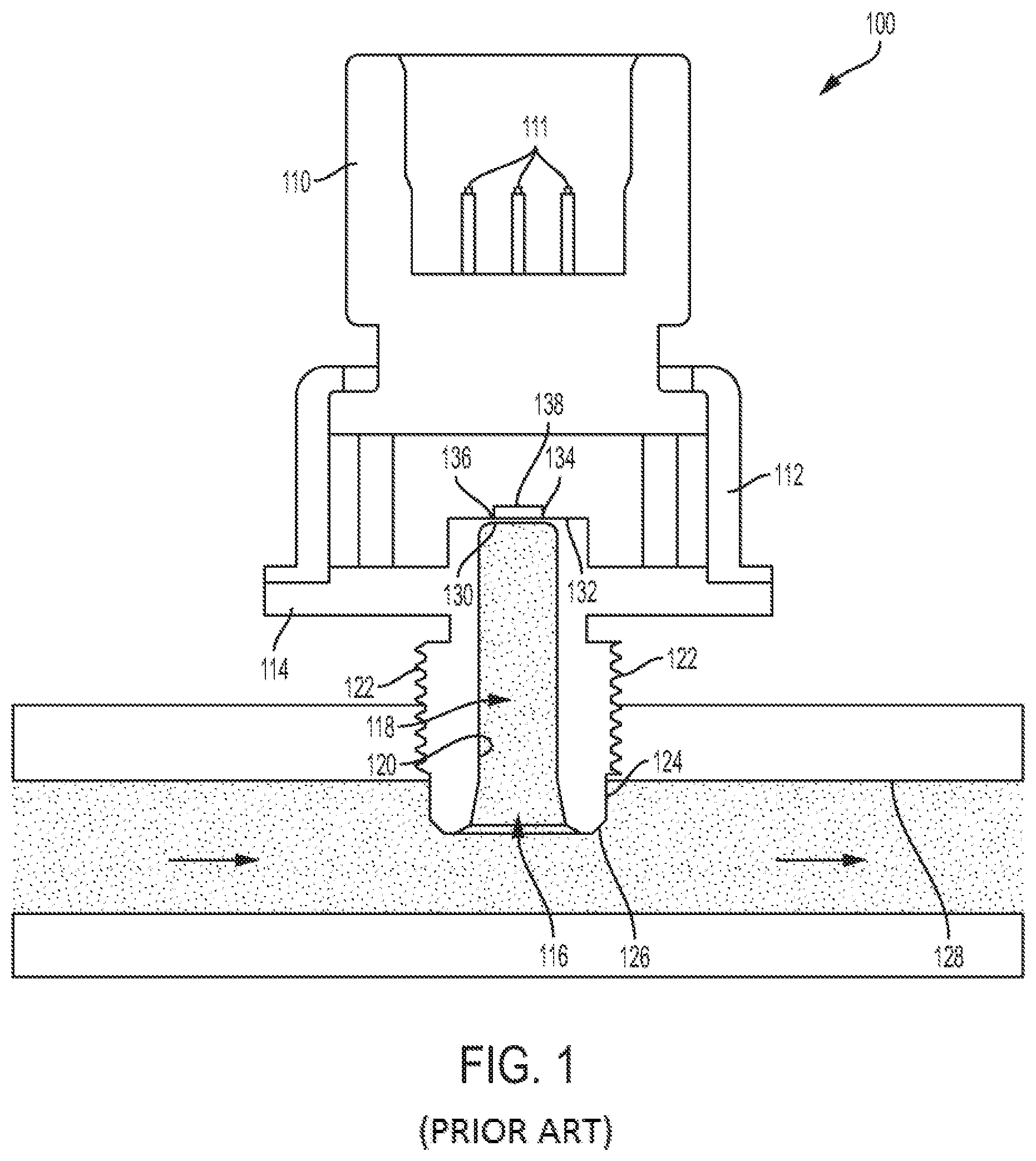
FIG. 1 is a cross sectional view of a prior art pressure sensor.
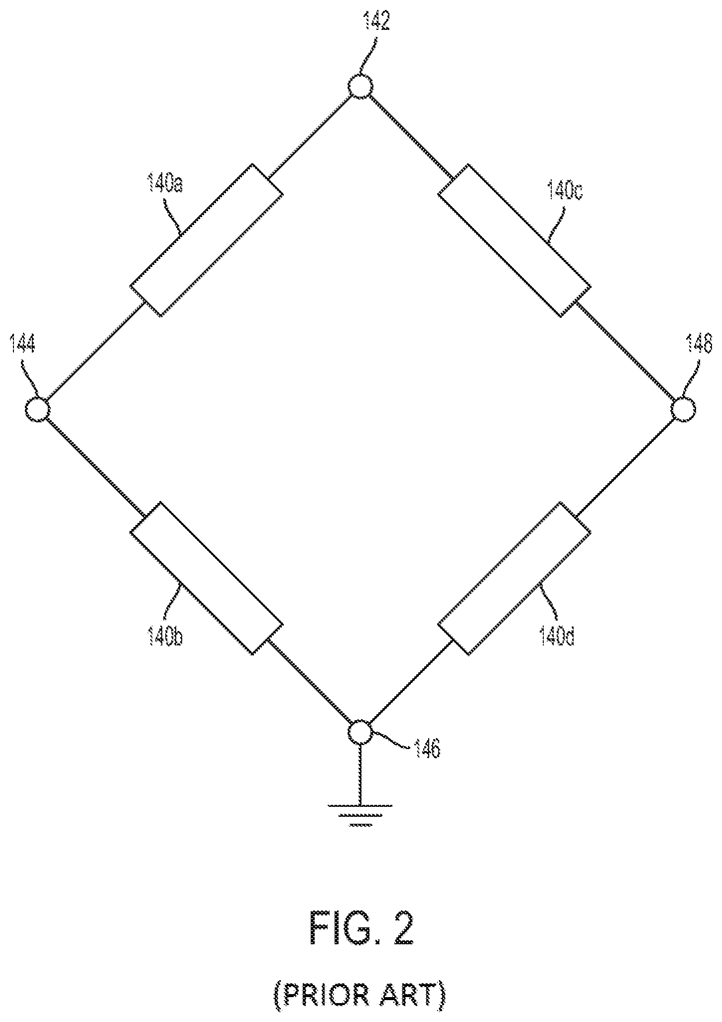
FIG. 2 is a schematic view of a prior art strain gauge forming a Wheatstone bridge.
FIG. 3 is a block diagram showing the operation of a prior art Wheatstone bridge in operation.
FIG. 4 is a cross sectional view of a strain gauge in accordance with the subject technology.
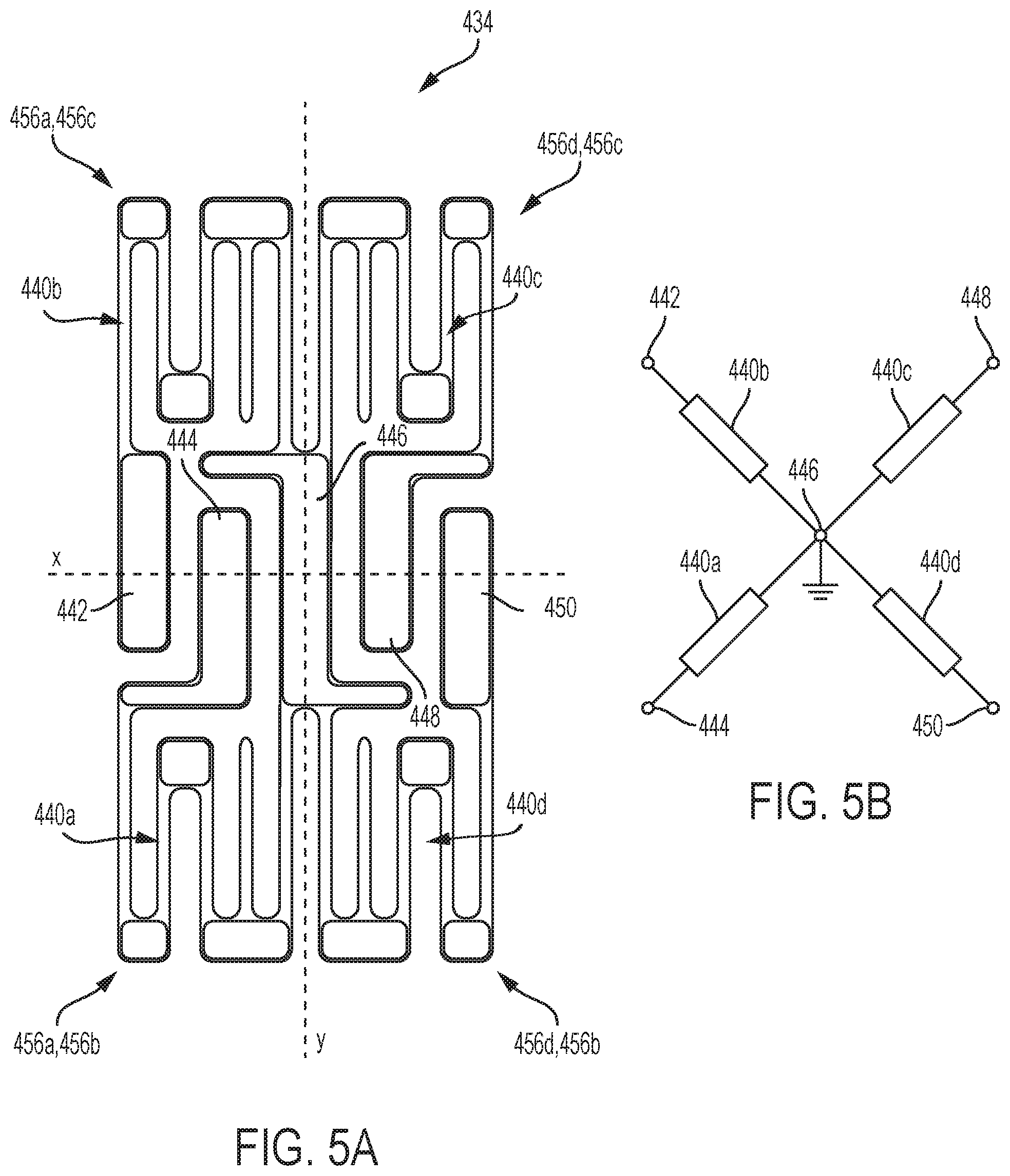
FIG. 5A is a top view of a strain gauge in accordance with the subject technology.
FIG. 5B is a simplified circuit diagram of the strain gauge of FIG. 5A.
FIG. 6 is a block diagram of the strain gauge of FIG. 5A.
FIG. 7 is a circuit diagram of the strain gauge of FIG. 5A.
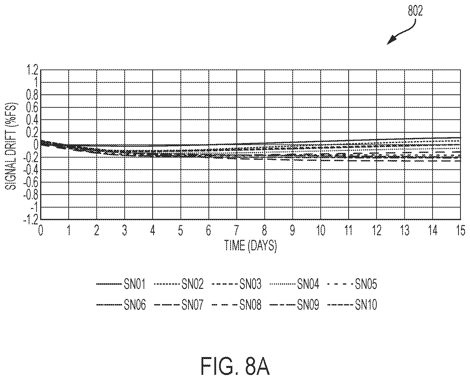
FIG. 8A is a graph showing testing data representing signal drift over time for strain gauges designed in accordance with the subject technology.
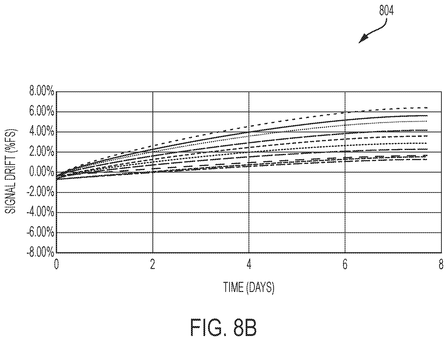
FIG. 8B is a graph showing testing data representing signal drift over time for prior art strain gauges.
DETAILED DESCRIPTION
The subject technology overcomes many of the prior art problems associated with pressure sensors. In brief summary, the subject technology provides a pressure sensor and corresponding strain gauge that significantly reduce signal drift as compared to prior art sensors. The advantages, and other features of the systems and methods disclosed herein, will become more readily apparent to those having ordinary skill in the art from the following detailed description of certain preferred embodiments taken in conjunction with the drawings which set forth representative embodiments of the present invention. Like reference numerals are used herein to denote like parts. Further, words denoting orientation such as "upper", "lower", "distal", and "proximate" are merely used to help describe the location of components with respect to one another. For example, an "upper" surface of a part is merely meant to describe a surface that is separate from the "lower" surface of that same part. No words denoting orientation are used to describe an absolute orientation (i.e. where an "upper" part must always be on top).
Further, resistors, and other features describe herein which are numbered, are numbered only to facilitate a discussion of those features with respect to one another. The numbers of each component do not refer to any particular order (e.g. where one must become before two) and in various embodiments any number of one component can switch numbers with another numbered component. For example, if a first and second resistor are described, the second resistor could just as appropriately be deemed the first resistor while the resistor formerly called the first resistor is called the second resistor. Additionally, when a number of similar components are identified with like reference numerals (e.g. two resistors are given reference numerals 140a and 140b) the components are sometimes referred to collectively with a single reference numeral (e.g. just 140).
Referring now to FIG. 1, a cross sectional view of a prior art pressure sensor 100 is shown. The pressure sensor is configured for use within various applications, such as a motorized vehicle. For example, the pressure sensor 100 can measure the pressure of transmission fluid, brake fluid, or engine oil.
A connector 110, a housing 112, and a solid steel port body 114 are coupled together to enclose the other components of the pressure sensor 100. A distal opening 116 in the port body 114 allows fluid to flow from a fluid medium into an interior channel 118 defined by peripheral walls 120 of the port body 114. Ridges 122 on the exterior 124 of the port body 114 allow fixation of the distal end 126 of the port body 114 to a structure 128 surrounding the fluid medium, keeping the interior channel 118 fluidly connected to the fluid medium.
The port body 114 also includes a diaphragm 130 at a proximate end 132 of the interior channel 118. The diaphragm 130 is formed from a steel wall that is relatively thinner as compared to the peripheral walls 120 of the port body 114. As fluid from the pressure medium enters and fills the interior channel 118, fluid pressure causes the diaphragm 130 to flex. A strain gauge 134, such as a microfused silicon strain gauge (MSG), is affixed to the top 136 of the diaphragm 130, for example, by an adhesive or substrate layer. The strain gauge 134 includes a number of sense elements, such as resistors or piezoresistive elements which change resistance as they flex in conjunction with the flexing of the diaphragm 130. The resistance of the resistors is relied upon to determine the pressure within the interior channel 118, and thus, pressure within the pressure medium. This resistance can be calculated, for example, by configuring the strain gauge 134 and corresponding resistors to form a Wheatstone bridge. Connector pins 111 allow signals for the strain gauge 134 to be delivered to external electronics (not shown herein).
Referring now to FIG. 2, a schematic of the circuitry of a prior art strain gauge 134 forming a Wheatstone bridge is shown. As described above, the strain gauge 134 and related processing circuitry act to calculate a pressure based on the resistance of the resistors 140. For example, a voltage supply 142 applies a voltage to the Wheatstone bridge. On one side of the Wheatstone bridge, shown here on the left, an electrical connection is formed between the voltage supply 142, a first bridge output voltage 144, and a ground pad 146. A first resistor 140a is disposed on the electrical connection between the voltage supply 142 and the bridge output voltage 144 and a second resistor 140b is disposed between the first bridge output voltage 144 and the ground pad 146. On the right side of the Wheatstone bridge, the voltage supply 142 is electrically connected to a second bridge output voltage 148 and the ground pad 146. A third resistor 140c is disposed on the electrical connection between the voltage supply 142 and the second bridge output voltage 148 and a fourth resistor 140d is disposed between the second bridge output voltage 148 and the ground pad 146.
As pressure is applied to the diaphragm 130, flexure of the diaphragm 130 causes a change in resistance to one or more of the resistors 140. A constant voltage is being input into the strain gauge 134 via the voltage supply 142. Therefore a change in resistance of one of the resistors 140 will cause a corresponding change in one of the bridge output voltages 144, 148. The change in output voltage is used to calculate the amount of flexure in the diaphragm and corresponding pressure change within the channel 118, and therefore, within the fluid medium. Notably, the term "Wheatstone bridge" as used herein is used merely to refer to an arrangement of components, such as contact pads and resistors 140, which work to generate a signal which can be relied upon to determine the resistance of one or more resistors 140. The processing circuitry which is relied upon to ultimately determine pressure may be separate from the strain gauge 134 shown herein.
Referring now to FIG. 3, a block diagram showing the operation of a prior art strain gauge 134 is shown. In the example given, the strain gauge 134 is operating in a harsh environment, such as part of an automotive application, and is subject to a high temperature (i.e. above 100 degrees Celsius). In some cases, the temperature may even reach a very high temperature (i.e. above 110 degrees Celsius) or greater. Due to the layout of the Wheatstone bridge, as shown in FIG. 2, the first resistor 140a is positioned relatively closer to the supply voltage 142 as compared to the second resistor 140b. Meanwhile the second resistor 140b is positioned relatively closer to the ground 146, as compared to the first resistor 140a.
Still referring to FIG. 3, the harsh environment has required the vehicle to continuously run, subjecting the strain gauge 134 to a high temperature. The strain gauge 134 has remained powered on with the steel port grounded, resulting in the creation of a number of mobile ions 152. The mobile ions 152 will accumulate on the resistors 140, and areas within those resistors 140 that are closest to the supply voltage 142 and furthest from the ground pad 146. Disparate mobile ions 152 accumulate across the resistors 140 will result in a mobile ion distribution with an unbalanced resistance change which can create a charging effect on the resistors 140 leading to sensor signal drift.
In the example shown in FIG. 3, the distribution graphs 154a, 154b (generally 154) under each resistor 140a, 140b represent the strength of the mobile ion distribution across those resistors 140a, 140b. The height of the graphical depiction of the mobile ion distribution 154 corresponds to the average total mobile ion 152 accumulation at the corresponding area of the resistor 140 (i.e. the area of each resistor 140 directly above that portion of the distribution graph 154. The first resistor 140a being closer to the voltage supply 142 and further from the ground pad 146, has a greater mobile ion accumulation, and thus a higher mobile ion distribution 154a, than the mobile ion distribution 154b of the second resistor 140b. Similarly, the mobile ion distribution graphs 154a, 154b of each resistor 140a, 140b increases according to proximity to the voltage supply 142 and distance from the ground pad 146.
Referring now to FIG. 4, a cross sectional view of a pressure sensor 400 in accordance with the subject technology is shown. A connector 410, a housing 412, and a solid steel port body 414 are coupled together to enclose the other components of the pressure sensor 400. A distal opening 416 in the port body 414 allows fluid to flow from a fluid medium into an interior channel 418 defined by peripheral walls 420 of the port body 414. Ridges 422 on the exterior 424 of the port body 414 allow fixation of the distal end 426 of the port body 414 to a structure 428 surrounding the fluid medium, keeping the interior channel 418 fluidly connected to the fluid medium.
The port body 414 also includes a diaphragm 430 at a proximate end 432 of the interior channel 418. The diaphragm 430 is formed from a steel wall that is relatively thinner as compared to the peripheral walls 420 of the port body 414. As fluid from the pressure medium enters and fills the interior channel 418, fluid pressure causes the diaphragm 430 to flex, while the peripheral walls 420 of the port body 414 are thick enough to hold their shape. A strain gauge 434, such as an MSG, is affixed to the top 436 of the diaphragm 430, for example, by an adhesive or substrate layer (e.g. a glass substrate 438). The strain gauge 434 includes a number of sense elements, such as resistors 440 (see FIG. 5A) or piezoresistive elements which change resistance as they flex in conjunction with the flexing of the diaphragm 430. The resistance of the resistors 440 is relied upon to determine the pressure within the interior channel 418, and thus, pressure within the pressure medium. The strain gauge 432 can transmit an output signal to external components for (not distinctly shown) for display or processing via connector pins 411. While the pressure sensor 400 has some similar features to the prior art pressure sensor 100, the most significant differences are described and shown herein. Notably, in the embodiment shown, the resistors 440 are directly attached to the port body 414, the only intervening layer being a glass substrate 438 or an adhesive.
In one embodiment, the pressure sensor 400 of the subject technology includes a strain gauge 434 which is positioned half over the diaphragm 430, and half over the thicker peripheral walls 420 of the port body 414. As a result, when the diaphragm 430 flexes, the portion of the strain gauge 434 over the diaphragm 430 is stretched and placed into tension, while the portion of the strain gauge 434 over the relatively inflexible peripheral walls 420 is placed into compression. Accordingly, this causes resistors 440 over the diaphragm 430 to experience a tension force while resistors 440 over the peripheral walls 420 to experience a compression force. As with the pressure sensor 100, resistance of the resistors 440 is relied upon to determine the pressure within the interior channel 118, and thus, pressure within the pressure medium. In the case of the pressure sensor 400, when the resistors 440 are piezoresistive elements, the differential in resistance between the resistors 440 in tension and the resistors 440 in compression can be further relied upon to enhance sensing accuracy.
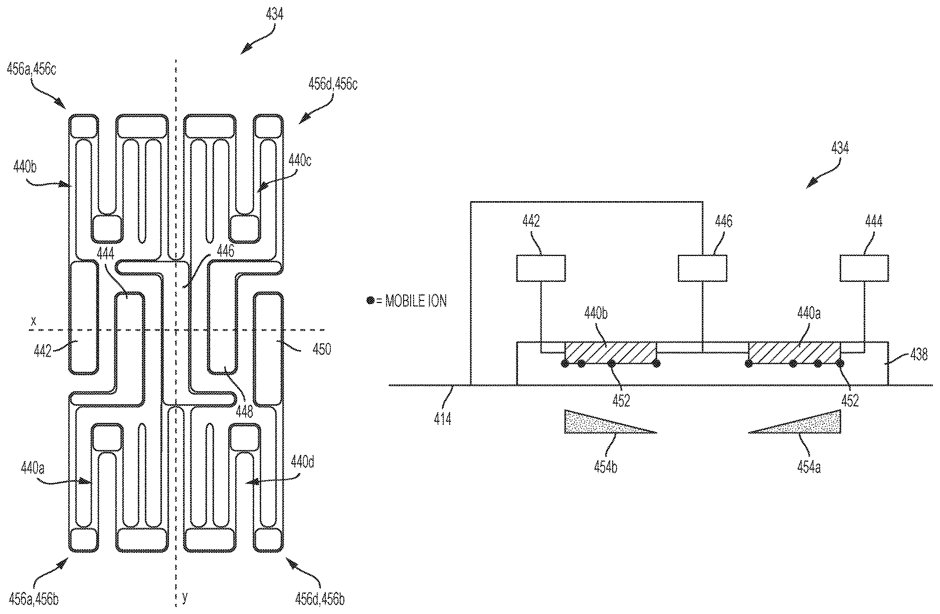
Referring now to FIGS. 5A and 5B, a top view of the mechanical configuration of a strain gauge 434, as well as a simplified circuit diagram of a strain gauge 434 in accordance with the subject technology are shown, respectively. While only a strain gauge 434 is shown for simplicity, it should be noted that it is envisioned that the strain gauge 434 will be utilized in accordance with the other components shown and described herein. For example, the strain gauge 434 can be attached to a pressure sensor 400 via a glass substrate 438, as shown in FIG. 4. Fi
Still referring to FIGS. 5A-5B, the strain gauge 434 contains four input/output pads (I/O) pads 442, 444, 448, 450 and a centrally positioned ground pad 446. The I/O pads 442, 444, 448, 450 are aligned along a lateral axis "x" and elongated along a longitudinal axis "y", such that they are all parallel along the longitudinal axis y. The longitudinal axis y passes lengthwise through the center of the ground pad 446 while the lateral axis x passes widthwise through the center of the ground pad 446. The strain gauge 434 also includes four resistors 440a, 440b, 440c, 440d (generally 440). A first resistor 440a electrically connects a first I/O pad 444 to the ground pad 446. The first resistor 440a is located on a first side 456a of the longitudinal axis y and a first side 456b of the lateral axis x. A second resistor 440b, located on the first side 456a of the longitudinal axis y and a second side 456c of the lateral axis x, connects the second I/O pad 442 to the ground pad 446. A third resistor 440c, positioned on the second side 456c of the lateral axis x and the second side 456d of the longitudinal axis y, connects the third I/O pad 448 to the ground pad 446. A fourth resistor 440d, positioned on the first side 456b of the first lateral axis x and the second side 456d of the longitudinal axis y, connects the fourth I/O pad 450 to the ground pad 446. The position of the resistors 440, with respect to the x and y axes, can also be described as quadrants. For example, the x and y axes form four quadrants with the first 440a, second 440b, third 440c, and fourth 440d resistors being positioned within the first 456a, 456b, second 456a, 456c, third 456d, 456c, and fourth 456d, 456b quadrants respectively.
The four resistors 440 can also be described as forming two pairs of resistors, the pairs being symmetrical about one or more of the axes x,y. For example, the first resistor 440a and the fourth resistor 440d can form a first resistor pair while the second resistor 440b and the third resistor 440c can form a second resistor pair. In such a case, the first resistor pair and the second resistor pair are symmetrical about the lateral axis x. Similarly, the first resistor 440a and the second resistor 440b can form a first resistor pair while the third resistor 440c and the fourth resistor 440d form a second resistor pair. The first resistor pair and the second resistor pair would then be symmetrical about the longitudinal axis y. In the example shown, there is symmetry between all resistors 440 about the axes. This symmetrical resistor orientation within the strain gauge 434 reduces pressure nonlinearity between the resistors 440. Further, the five pad 442, 444, 446, 448, 450 orientation, with symmetrical I/O pads 442, 444, 448, 450 surrounding the central ground pad 446, eases the wire bonding process, making assembly of the strain gauge 434 quicker and more cost efficient. The symmetrical resistor orientation also allows the resistors to be more easily placed on a desired location of the port body 414. For example, the strain gauge 434 can be placed with the first resistor 440a and fourth resistor 440d are placed the peripheral walls 420 of the strain gauge 434, while the second resistor 440b and third resistor 440c are placed over the diaphragm 430. In this configuration, fluid entering the channel 418 will apply a pressure to the diaphragm 430, causing the first resistor and the fourth resistor 440d to be in compression while the second resistor 440b and third resistor 440c are in compression.
Turning to FIG. 6, a block diaphragm of the strain gauge 434 of FIGS. 5A-5B is shown. In the example given, the strain gauge 434 is operating in a harsh environment, such as part of an automotive application, and is subject to a high temperature (i.e. above 100 degrees Celsius). In some cases, the temperature may even reach a very high temperature (i.e. above 110 degrees Celsius) or greater. The strain gauge 434 and circuitry are affixed to the port body 414 via a glass substrate 438. An input current is being applied to the strain gauge 434 via the I/O pads 442, 444. Due to the layout of the circuitry, the second resistor 440b is positioned substantially equidistant from the ground 446, as compared to the first resistor 440a. Both resistors 440, 440b are also positioned substantially equidistant from their corresponding I/O pad 442, 444. The term "substantially" as used in the phrase "substantially equidistant" herein, is defined as between 0 to 200 micrometers. In the embodiment shown, the port body 414 is a conductive material electrically connected to the ground. Therefore the ground pad 446 of the strain gauge 434 is grounded by a connection between the ground pad 446 and the port body 414.
Still referring to FIG. 6, the harsh environment has resulted in the creation of a number of mobile ions 452. The mobile ions 452 will accumulate on the resistors 440, and areas within those resistors 440, that are closest to supply current from the I/O pads 442, 444 and further from the ground 446. In the example shown in FIG. 6, the first and second resistors 440a, 440b are spaced from the ground pad 446 to urge uniform mobile ion 452 accumulation across the first and second resistors 440a, 440b. In other words, each resistor 440 is spaced substantially equidistant from the ground pad 446 to urge uniform mobile ion 452 accumulation across the resistors 440. Mobile ion 452 accumulation across the first resistor 440a is graphically depicted by mobile ion distribution graph 454a and the mobile ion 452 accumulation across the second resistor 440b is graphically depicted by mobile ion distribution graph 454b. The configuration of each resistor 440 being substantially equidistant from the ground pad 446 reduces mobile ion 452 migration. Thus, the first resistor 440a has approximately the same mobile ion 452 accumulation, and approximately the same mobile ion distribution graph 454a as the mobile ion 452 accumulation and distribution graph 454b for the second resistor 440b. Note that the height of the graphical depictions 454 of the mobile ion distribution 454 corresponds to average total mobile ion 452 accumulation at the corresponding area of each resistor 440a, 440b (e.g. the area of each resistor 440a, 440b at a similar distance from the central ground pad 446). Balanced mobile ion 452 accumulating across the resistors 440a, 440b results in a balanced resistance charge (i.e. the first resistor 440a is reducing at the same rate as the second resistor 440b). This advantageously prevents creation of a charging effect on the resistors 440 and reduces or eliminates sensor signal drift.
Turning to FIG. 7, a more complete circuit diagram of the strain gauge of FIGS. 5A-5B is shown. A first resistor 440a is electrically connected between a first I/O pad 444 and a ground pad 446. A second resistor 440b is electrically connected between a second I/O pad 442 and the ground pad 446. Additionally, a third resistor 440c is electrically connected between a third I/O pad 448 and the ground pad 446, while a fourth resistor 440d is electrically connected between a fourth I/O pad 450 and the ground pad 446. Each resistor 440 is positioned to be substantially equidistant from the ground pad 446 to urge uniform mobile ion 452 accumulation across the resistors 440. Four current sources 458a, 458b, 458c, 458d (generally 458), each provide a uniform, constant current to one of the I/O pads 442, 444, 448, 450. A first output 460a is electrically connected between the first I/O pad 444 and the second I/O pad 442 and a second output 460b is electrically connected between the third I/O pad 448 and the fourth I/O pad 450, the output 460 configured to measure a change in voltage. More specifically, when the resistance of the resistors 440 changes due to pressure, the outputs 460 sense a corresponding voltage change which can be used to calculate pressure. In other embodiments, a constant voltage can be applied as an input, instead of current sources 458, and the outputs 460 can be configured to measure a change in current.
Notably, while an electrical configuration of four resistors 440 is shown, this is for redundancy and only two resistors 440 need to be used in some embodiments. For example, the strain gauge 434 could be configured with only resistors 440a and 440b, output 460a, grounding pad 446, and the first and second I/O pads 442, 444. In some embodiments, the first resistor 440a would be placed above the peripheral walls 420 of the port body 414 such that it would experience a compression force, while the second resistor 440b would be placed above the diaphragm 430 to experience a tension force. The output 460a, would then measure the resistance differential (e.g. by sensing a voltage or current across the circuit) generated when the resistors 440b, 440a were placed in tension and compression, respectively. Similarly, with the four resistor 440 configuration shown, the third resistor 440c could be placed in tension while the fourth resistor 440d is placed in compression, such that the output 460b measures the resistance differential. Therefore having four resistors 440 allows for each pair of resistors (e.g. 440a, 440b and 440c, 440d) to serve as a check on the other pair.
Turning to FIG. 8A and FIG. 8B, graphs 802, 804 of test data showing the signal drift of various strain gauges are shown. Graph 802 of FIG. 8A represents the signal drift data of tests on a number of strain gauges configured in accordance with the subject technology, while graph 804 of FIG. 8B represents the signal drift of prior art strain gauges. To generate the data, a hot soak test was performed at 140 degrees Celsius for 300 hours on powered strain gauges. As can be seen, the signal drift of prior art strain gauges (graph 804) at times approached 6.00% by the 8.sup.th day of testing. By contrast, the error of all strain gauges of the subject technology (graph 802) was less than 0.2% at the 8.sup.th day. Overall, the new design reduced signal drift by an average of approximately 95%.
It will be appreciated by those of ordinary skill in the pertinent art that the functions of several elements may, in alternative embodiments, be carried out by fewer elements or a single element. Similarly, in some embodiments, any functional element may perform fewer, or different, operations than those described with respect to the illustrated embodiment. Also, functional elements (e.g., electronics, input and output sources, connection pads, and the like) shown as distinct for purposes of illustration may be incorporated within other functional elements in a particular implementation.
While the subject technology has been described with respect to preferred embodiments, those skilled in the art will readily appreciate that various changes and/or modifications can be made to the subject technology without departing from the spirit or scope of the subject technology. For example, each claim may depend from any or all claims in a multiple dependent manner even though such has not been originally claimed.
* * * * *
D00000
D00001
D00002
D00003
D00004
D00005
D00006
D00007
D00008
D00009
XML
uspto.report is an independent third-party trademark research tool that is not affiliated, endorsed, or sponsored by the United States Patent and Trademark Office (USPTO) or any other governmental organization. The information provided by uspto.report is based on publicly available data at the time of writing and is intended for informational purposes only.
While we strive to provide accurate and up-to-date information, we do not guarantee the accuracy, completeness, reliability, or suitability of the information displayed on this site. The use of this site is at your own risk. Any reliance you place on such information is therefore strictly at your own risk.
All official trademark data, including owner information, should be verified by visiting the official USPTO website at www.uspto.gov. This site is not intended to replace professional legal advice and should not be used as a substitute for consulting with a legal professional who is knowledgeable about trademark law.