Tapping devices, systems and methods for use in bone tissue
Magee , et al. Feb
U.S. patent number 10,555,758 [Application Number 15/230,198] was granted by the patent office on 2020-02-11 for tapping devices, systems and methods for use in bone tissue. This patent grant is currently assigned to Woven Orthopedic Technologies, LLC. The grantee listed for this patent is Woven Orthopedic Technologies, LLC. Invention is credited to Robert Luzzi, Lynn MacDonald, Francis Patrick Magee, Jeffrey P. Radziunas.


View All Diagrams
| United States Patent | 10,555,758 |
| Magee , et al. | February 11, 2020 |
Tapping devices, systems and methods for use in bone tissue
Abstract
A soft tapping device for preparing a bone hole that includes a substantially cylindrical insert that is sized to enter into a compressed woven retention device. The substantially cylindrical insert has protrusions that are adaptable to expand portions of a compressed woven retention device inside the bone hole. The substantially cylindrical insert is also configured to exit from the compressed woven retention device without changing the expanded portions of the compressed woven retention device.
| Inventors: | Magee; Francis Patrick (Mackay, ID), Luzzi; Robert (Silverthorne, CO), Radziunas; Jeffrey P. (Wallingford, CT), MacDonald; Lynn (Bantam, CT) | ||||||||||
|---|---|---|---|---|---|---|---|---|---|---|---|
| Applicant: |
|
||||||||||
| Assignee: | Woven Orthopedic Technologies,
LLC (Manchester, CT) |
||||||||||
| Family ID: | 57944170 | ||||||||||
| Appl. No.: | 15/230,198 | ||||||||||
| Filed: | August 5, 2016 |
Prior Publication Data
| Document Identifier | Publication Date | |
|---|---|---|
| US 20170035482 A1 | Feb 9, 2017 | |
Related U.S. Patent Documents
| Application Number | Filing Date | Patent Number | Issue Date | ||
|---|---|---|---|---|---|
| 62201273 | Aug 5, 2015 | ||||
| 62287756 | Jan 27, 2016 | ||||
| Current U.S. Class: | 1/1 |
| Current CPC Class: | A61B 17/8872 (20130101); A61B 17/686 (20130101); A61B 17/1655 (20130101); A61B 17/863 (20130101); A61L 31/028 (20130101); A61L 2430/02 (20130101); A61B 17/1617 (20130101); A61B 2017/8655 (20130101) |
| Current International Class: | A61B 17/86 (20060101); A61L 31/02 (20060101); A61B 17/88 (20060101); A61B 17/68 (20060101) |
References Cited [Referenced By]
U.S. Patent Documents
| 517668 | April 1894 | Still |
| 1486527 | March 1924 | Larkin |
| 1516652 | November 1924 | Tomkinson |
| 1517668 | December 1924 | Daudelin |
| 2148164 | February 1939 | Krippendorf |
| 2326453 | August 1943 | Gelpcke |
| 2388693 | November 1945 | Jeckel |
| 2879687 | March 1959 | Leimbach |
| 2936670 | May 1960 | Walter |
| 2983182 | May 1961 | Shobert |
| 3054406 | September 1962 | Usher |
| 3187752 | June 1965 | Glick |
| 3199398 | August 1965 | Weisz |
| 3232163 | February 1966 | Croessant |
| 3363502 | January 1968 | Florentine |
| 3371573 | March 1968 | Koreki |
| 3710789 | January 1973 | Ersek |
| 3714862 | February 1973 | Berger |
| 3921496 | November 1975 | Helderman |
| 4011602 | March 1977 | Rybicki et al. |
| 4064567 | December 1977 | Burstein et al. |
| 4158984 | June 1979 | Griffiths |
| 4182339 | January 1980 | Hardy, Jr. |
| 4205399 | June 1980 | Shalaby et al. |
| 4304169 | December 1981 | Cimprich et al. |
| 4383527 | May 1983 | Asnis et al. |
| 4394370 | July 1983 | Jefferies |
| 4409974 | October 1983 | Freedland |
| 4453539 | June 1984 | Raftopoulos et al. |
| 4520821 | June 1985 | Schmidt et al. |
| 4563489 | January 1986 | Urist |
| 4566466 | January 1986 | Ripple et al. |
| 4567917 | February 1986 | Millard |
| 4584722 | April 1986 | Levy et al. |
| 4610688 | September 1986 | Silvestrini et al. |
| 4640271 | February 1987 | Lower |
| 4693721 | September 1987 | Ducheyne |
| 4708132 | November 1987 | Silvestrini |
| 4711232 | December 1987 | Fischer et al. |
| 4716807 | January 1988 | Fischer |
| 4716893 | January 1988 | Fischer et al. |
| 4753149 | June 1988 | Celani |
| 4760843 | August 1988 | Fischer et al. |
| 4776330 | October 1988 | Chapman et al. |
| 4777860 | October 1988 | Bassett et al. |
| 4790852 | December 1988 | Noiles |
| 4803909 | February 1989 | Smith |
| 4870957 | October 1989 | Goble et al. |
| 4894063 | January 1990 | Nashef |
| 4913028 | April 1990 | Yoshiya |
| 4917700 | April 1990 | Aikins |
| 5013318 | May 1991 | Spranza, III |
| 5041114 | August 1991 | Chapman et al. |
| 5059211 | October 1991 | Stack et al. |
| 5084050 | January 1992 | Draenert |
| 5171148 | December 1992 | Wasserman et al. |
| 5186992 | February 1993 | Kite, III |
| 5211647 | May 1993 | Schmieding |
| 5221261 | June 1993 | Termin et al. |
| 5257571 | November 1993 | Richardson |
| 5268001 | December 1993 | Nicholson et al. |
| 5300075 | April 1994 | Gordon |
| 5354292 | October 1994 | Braeuer et al. |
| 5380334 | January 1995 | Torrie et al. |
| 5383387 | January 1995 | Chesterfield et al. |
| 5385077 | January 1995 | Akiyama et al. |
| 5443499 | August 1995 | Schmitt |
| 5456721 | October 1995 | Legrand |
| 5458601 | October 1995 | Young, Jr. et al. |
| 5490750 | February 1996 | Gundy |
| 5501133 | March 1996 | Brookstein et al. |
| 5520084 | May 1996 | Chesterfield et al. |
| 5571184 | November 1996 | DeSatnick |
| 5628788 | May 1997 | Pinchuk |
| 5629077 | May 1997 | Turnlund et al. |
| 5641256 | June 1997 | Gundy |
| 5713904 | February 1998 | Errico et al. |
| 5716359 | February 1998 | Ojima et al. |
| 5718159 | February 1998 | Thompson |
| 5725541 | March 1998 | Anspach, III et al. |
| 5741325 | April 1998 | Chaikof et al. |
| 5756457 | May 1998 | Wang et al. |
| 5758562 | June 1998 | Thompson |
| 5766250 | June 1998 | Chervitz et al. |
| 5785713 | July 1998 | Jobe |
| D397794 | September 1998 | Geber |
| 5849013 | December 1998 | Whittaker et al. |
| 5871504 | February 1999 | Eaton et al. |
| 5876432 | March 1999 | Lau et al. |
| 5904685 | May 1999 | Walawalkar |
| 5935129 | August 1999 | McDevitt et al. |
| 5941901 | August 1999 | Egan |
| 5957974 | September 1999 | Thompson et al. |
| 5961524 | October 1999 | Crombie |
| 5981926 | November 1999 | Kim |
| 5984926 | November 1999 | Jones |
| 6019786 | February 2000 | Thompson |
| 6039740 | March 2000 | Olerud |
| 6042592 | March 2000 | Schmitt |
| 6056751 | May 2000 | Fenton, Jr. |
| 6068632 | May 2000 | Carchidi et al. |
| 6080155 | June 2000 | Michelson |
| 6099530 | August 2000 | Simonian et al. |
| 6126663 | October 2000 | Hair |
| 6143029 | November 2000 | Rippstein |
| 6231606 | May 2001 | Graf et al. |
| 6241757 | June 2001 | An et al. |
| 6264676 | July 2001 | Gellman et al. |
| 6283966 | September 2001 | Houfburg |
| 6314856 | November 2001 | Keith et al. |
| 6319255 | November 2001 | Grundei et al. |
| 6325822 | December 2001 | Chouinard et al. |
| 6336940 | January 2002 | Graf et al. |
| 6342068 | January 2002 | Thompson |
| 6355044 | March 2002 | Hair |
| 6375662 | April 2002 | Schmitt |
| 6398807 | June 2002 | Chouinard et al. |
| 6413260 | July 2002 | Berrevoets et al. |
| 6436142 | August 2002 | Paes et al. |
| 6450770 | September 2002 | Wang et al. |
| 6495227 | December 2002 | Cahuzac |
| 6500203 | December 2002 | Thompson et al. |
| 6540770 | April 2003 | Tornier et al. |
| 6544281 | April 2003 | ElAttrache et al. |
| 6551352 | April 2003 | Clerc et al. |
| 6562046 | May 2003 | Sasso |
| 6582461 | June 2003 | Burmeister et al. |
| 6616694 | September 2003 | Hart |
| 6616996 | September 2003 | Keith et al. |
| 6622604 | September 2003 | Chouinard et al. |
| 6631666 | October 2003 | Cahuzac |
| 6645211 | November 2003 | Magana |
| 6652571 | November 2003 | White et al. |
| 6669706 | December 2003 | Schmitt et al. |
| 6685738 | February 2004 | Chouinard et al. |
| 6746483 | June 2004 | Bojarski |
| 6767350 | July 2004 | Lob |
| 6792979 | September 2004 | Konya et al. |
| 6814734 | November 2004 | Chappuis et al. |
| 6817076 | November 2004 | Stephenson |
| 6827743 | December 2004 | Eisermann et al. |
| 6840769 | January 2005 | Augthun et al. |
| 6863692 | March 2005 | Meulink |
| D503802 | April 2005 | Bjarnason |
| 6875216 | April 2005 | Wolf |
| 6908466 | June 2005 | Bonutti et al. |
| 6942666 | September 2005 | Overaker et al. |
| 6942693 | September 2005 | Chouinard et al. |
| 6991647 | January 2006 | Jadhav |
| 7004967 | February 2006 | Chouinard et al. |
| 7022124 | April 2006 | Takei et al. |
| 7052513 | May 2006 | Thompson |
| 7093527 | August 2006 | Rapaport et al. |
| 7101183 | September 2006 | Augthun et al. |
| 7141074 | November 2006 | Fanger et al. |
| 7144413 | December 2006 | Wilford et al. |
| 7213495 | May 2007 | McCullagh et al. |
| 7237466 | July 2007 | Chen |
| 7255712 | August 2007 | Steinberg |
| 7275471 | October 2007 | Nishri et al. |
| 7279008 | October 2007 | Brown et al. |
| 7309355 | December 2007 | Donnelly et al. |
| 7311031 | December 2007 | McCullagh et al. |
| 7341592 | March 2008 | Walters et al. |
| 7341601 | March 2008 | Eisermann et al. |
| 7344559 | March 2008 | Gray et al. |
| 7407512 | August 2008 | Bojarski et al. |
| 7435254 | October 2008 | Chouinard et al. |
| 7513865 | April 2009 | Boume et al. |
| 7547321 | June 2009 | Silvestri et al. |
| 7569058 | August 2009 | Zwimmann |
| 7572283 | August 2009 | Meridew |
| 7572298 | August 2009 | Roller et al. |
| 7582108 | September 2009 | Hierlemann et al. |
| 7637949 | December 2009 | Hart |
| D612499 | March 2010 | Ondracek et al. |
| 7682392 | March 2010 | Serhan et al. |
| 7699893 | April 2010 | Donnelly et al. |
| 7731750 | June 2010 | Bojarski et al. |
| 7740657 | June 2010 | Brown, Jr. et al. |
| 7749233 | July 2010 | Farr et al. |
| 7758642 | July 2010 | Bojarski et al. |
| 7785357 | August 2010 | Guan et al. |
| D626648 | November 2010 | Ahlgren |
| 7824433 | November 2010 | Williams |
| 7833249 | November 2010 | Shaolian et al. |
| 7846162 | December 2010 | Nelson et al. |
| 7892203 | February 2011 | Lenker et al. |
| 7896901 | March 2011 | Whittaker |
| 7938853 | May 2011 | Chouinard et al. |
| 7963972 | June 2011 | Foerster et al. |
| 7967851 | June 2011 | Bickley et al. |
| 7988732 | August 2011 | Bojarski et al. |
| 8052720 | November 2011 | Kuester et al. |
| 8100969 | January 2012 | Hart |
| 8114079 | February 2012 | Haidukewych et al. |
| 8114141 | February 2012 | Appenzeller et al. |
| 8128626 | March 2012 | Justin |
| 8142415 | March 2012 | Warnock, Jr. et al. |
| 8151682 | April 2012 | Lilburn et al. |
| 8162998 | April 2012 | Schlienger et al. |
| 8163031 | April 2012 | Truckai et al. |
| 8202306 | June 2012 | Dreyfuss |
| 8221479 | July 2012 | Glazer et al. |
| 8226714 | July 2012 | Beck, Jr. et al. |
| 8226715 | July 2012 | Hwang et al. |
| 8241340 | August 2012 | Froehlich |
| 8257395 | September 2012 | Bhatnagar et al. |
| 8298262 | October 2012 | Stone et al. |
| 8308779 | November 2012 | Reiley |
| 8317799 | November 2012 | Schon et al. |
| 8317863 | November 2012 | Cauldwell et al. |
| 8347772 | January 2013 | Dow et al. |
| 8353941 | January 2013 | Fricker et al. |
| 8361078 | January 2013 | Beyar et al. |
| 8366711 | February 2013 | Rabiner et al. |
| 8372115 | February 2013 | Kohm et al. |
| 8382849 | February 2013 | Thomas |
| 8414635 | April 2013 | Hyodoh et al. |
| 8419780 | April 2013 | Bickley et al. |
| 8420113 | April 2013 | Zhao |
| 8435293 | May 2013 | Donnelly et al. |
| 8443706 | May 2013 | Egres, Jr. |
| 8459164 | June 2013 | Lilburn et al. |
| 8493705 | July 2013 | Lin et al. |
| 8496705 | July 2013 | Hart |
| 8506605 | August 2013 | Bickley et al. |
| 8523902 | September 2013 | Heaven et al. |
| 8523916 | September 2013 | Anderson et al. |
| 8523951 | September 2013 | Kania |
| 8545499 | October 2013 | Lozier et al. |
| 8546456 | October 2013 | Rose et al. |
| 8546546 | October 2013 | Nakano |
| 8546752 | October 2013 | Henion et al. |
| 8568413 | October 2013 | Mazur et al. |
| 8585762 | November 2013 | Hall |
| 8591582 | November 2013 | Anderson et al. |
| 8617185 | December 2013 | Bonutti et al. |
| 8628464 | January 2014 | Bourne et al. |
| 8636753 | January 2014 | Buevich et al. |
| 8652171 | February 2014 | Stone et al. |
| 8663296 | March 2014 | Williams |
| 8663672 | March 2014 | Manrique et al. |
| 8671815 | March 2014 | Hancock et al. |
| 8677874 | March 2014 | Lilburn et al. |
| 8690962 | April 2014 | Dignam et al. |
| 8696748 | April 2014 | Bojarski et al. |
| 8709055 | April 2014 | Beyar et al. |
| 8721519 | May 2014 | Sheu et al. |
| 8747469 | June 2014 | Wang et al. |
| 8747470 | June 2014 | Beck, Jr. et al. |
| 8753391 | June 2014 | Lu et al. |
| 8770081 | July 2014 | David et al. |
| 8794118 | August 2014 | Dow et al. |
| 8821090 | September 2014 | Gruber |
| 8833224 | September 2014 | Thompson et al. |
| 8840677 | September 2014 | Kale et al. |
| 8857304 | October 2014 | Govari et al. |
| 8858606 | October 2014 | Graf et al. |
| 8870877 | October 2014 | Koogle, Jr. |
| 8910554 | December 2014 | Kinugasa |
| D723166 | February 2015 | Igaki et al. |
| 8951293 | February 2015 | Glazer et al. |
| 8956394 | February 2015 | McDonnell |
| 8956410 | February 2015 | Donnelly et al. |
| 8992537 | March 2015 | McDonnell |
| 9011440 | April 2015 | Schlienger et al. |
| 9060809 | June 2015 | Tipirneni et al. |
| D740427 | October 2015 | McDonnell et al. |
| 9388517 | July 2016 | Lilburn et al. |
| 9416472 | August 2016 | Scherrible et al. |
| 9532806 | January 2017 | McDonnell |
| 9585695 | March 2017 | Jones et al. |
| 9907593 | March 2018 | McDonnell |
| 9943351 | April 2018 | McDonnell et al. |
| 2002/0055749 | May 2002 | Esnouf et al. |
| 2002/0083821 | July 2002 | Uchida |
| 2002/0143340 | October 2002 | Kaneko |
| 2002/0147454 | October 2002 | Neto |
| 2003/0036761 | February 2003 | Smothers et al. |
| 2003/0045880 | March 2003 | Michelson |
| 2004/0024456 | February 2004 | Brown, Jr. et al. |
| 2004/0068267 | April 2004 | Harvie et al. |
| 2004/0094024 | May 2004 | Kim |
| 2004/0133204 | July 2004 | Davies |
| 2004/0176767 | September 2004 | Bickley |
| 2005/0015154 | January 2005 | Lindsey et al. |
| 2005/0070930 | March 2005 | Kammerer |
| 2005/0150370 | July 2005 | Nishri et al. |
| 2005/0216006 | September 2005 | Orbay et al. |
| 2005/0216012 | September 2005 | Willmen |
| 2005/0251143 | November 2005 | Dillard |
| 2005/0255230 | November 2005 | Clerc et al. |
| 2006/0089646 | April 2006 | Bonutti |
| 2006/0129148 | June 2006 | Simmons et al. |
| 2007/0038221 | February 2007 | Fine et al. |
| 2007/0060923 | March 2007 | Dreyfuss |
| 2007/0093899 | April 2007 | Dutoit et al. |
| 2007/0118131 | May 2007 | Gooch |
| 2007/0118144 | May 2007 | Truckai et al. |
| 2007/0191956 | August 2007 | Prewett et al. |
| 2007/0250114 | October 2007 | Drapeau |
| 2007/0270941 | November 2007 | Headley et al. |
| 2008/0027445 | January 2008 | Brown et al. |
| 2008/0051793 | February 2008 | Erickson et al. |
| 2008/0221623 | September 2008 | Gooch |
| 2008/0221624 | September 2008 | Gooch |
| 2008/0255560 | October 2008 | Myers et al. |
| 2008/0262630 | October 2008 | Fulmer et al. |
| 2008/0281430 | November 2008 | Kelman et al. |
| 2009/0024147 | January 2009 | Ralph et al. |
| 2009/0136898 | May 2009 | Kim |
| 2009/0192609 | July 2009 | Klabunde et al. |
| 2009/0193961 | August 2009 | Jensen et al. |
| 2009/0216338 | August 2009 | Gingras et al. |
| 2009/0254124 | October 2009 | Bickley et al. |
| 2009/0279980 | November 2009 | Gruber |
| 2009/0306777 | December 2009 | Widmer et al. |
| 2010/0015286 | January 2010 | Ghodsian et al. |
| 2010/0016940 | January 2010 | Shokoohi et al. |
| 2010/0042293 | February 2010 | Moshchuk et al. |
| 2010/0076503 | March 2010 | Beyar et al. |
| 2010/0125273 | May 2010 | Schwieger et al. |
| 2010/0152786 | June 2010 | Behrbalk |
| 2010/0168505 | July 2010 | Inman et al. |
| 2010/0179591 | July 2010 | Saltzman et al. |
| 2010/0185244 | July 2010 | Gooch |
| 2010/0292738 | November 2010 | Reiley |
| 2010/0318085 | December 2010 | Austin et al. |
| 2010/0324607 | December 2010 | Davis |
| 2010/0331881 | December 2010 | Hart |
| 2011/0061519 | March 2011 | Fields |
| 2011/0106177 | May 2011 | Lewis |
| 2011/0144766 | June 2011 | Kale et al. |
| 2011/0184472 | July 2011 | Niederberger et al. |
| 2011/0213467 | September 2011 | Lozier et al. |
| 2011/0230948 | September 2011 | Ehrenreich et al. |
| 2011/0238069 | September 2011 | Zajac et al. |
| 2012/0065649 | March 2012 | Towler |
| 2012/0123416 | May 2012 | Gelfand et al. |
| 2012/0172934 | July 2012 | Fisher et al. |
| 2012/0239145 | September 2012 | Peterson et al. |
| 2012/0245704 | September 2012 | Childs |
| 2012/0259372 | October 2012 | Glazer et al. |
| 2012/0264084 | October 2012 | Hansson et al. |
| 2013/0013065 | January 2013 | Bills |
| 2013/0014544 | January 2013 | Winkler |
| 2013/0018318 | January 2013 | Ravichandran et al. |
| 2013/0103166 | April 2013 | Butler et al. |
| 2013/0131684 | May 2013 | Farrell |
| 2013/0178946 | July 2013 | Monaghan et al. |
| 2013/0184819 | July 2013 | Donnelly et al. |
| 2013/0226204 | August 2013 | Kumar |
| 2013/0289621 | October 2013 | Fulmer et al. |
| 2014/0046454 | February 2014 | Rose et al. |
| 2014/0052178 | February 2014 | Dooney, Jr. |
| 2014/0090549 | April 2014 | Hurlen |
| 2014/0094805 | April 2014 | Bonutti et al. |
| 2014/0094860 | April 2014 | Reimels |
| 2014/0100590 | April 2014 | Gingras et al. |
| 2014/0128916 | May 2014 | Williams |
| 2014/0135906 | May 2014 | Winner et al. |
| 2014/0171946 | June 2014 | Benson et al. |
| 2014/0194938 | July 2014 | Bojarski et al. |
| 2014/0207145 | July 2014 | Sennett |
| 2014/0243978 | August 2014 | Beck, Jr. et al. |
| 2014/0277150 | September 2014 | Jones et al. |
| 2014/0277449 | September 2014 | Jones |
| 2014/0358145 | December 2014 | Schaller et al. |
| 2015/0018878 | January 2015 | Rizk et al. |
| 2015/0045831 | February 2015 | Allen |
| 2015/0119984 | April 2015 | Donnelly et al. |
| 2015/0148883 | May 2015 | Hyodoh et al. |
| 2015/0238205 | August 2015 | Reiley |
| 2015/0275408 | October 2015 | Tahara et al. |
| 2015/0313720 | November 2015 | Lorio |
| 2015/0342764 | December 2015 | Ramzipoor et al. |
| 2016/0010248 | January 2016 | Lariviere et al. |
| 2016/0038187 | February 2016 | McDonnell |
| 2016/0038206 | February 2016 | McDonnell |
| 2016/0058524 | March 2016 | Tehrani et al. |
| 2016/0074071 | March 2016 | McDonnell et al. |
| 2016/0074072 | March 2016 | McDonnell et al. |
| 2016/0074084 | March 2016 | McDonnell et al. |
| 2016/0168769 | June 2016 | McDonnell |
| 2016/0183942 | June 2016 | Allen |
| 2016/0317332 | November 2016 | Lilburn et al. |
| 2016/0345676 | December 2016 | Bruce et al. |
| 2017/0035481 | February 2017 | Magee et al. |
| 2017/0035482 | February 2017 | Magee et al. |
| 2017/0071634 | March 2017 | McDonnell |
| 2017/0128100 | May 2017 | Jones et al. |
| 2017/0165077 | June 2017 | McDonnell |
| 2017/0215934 | August 2017 | McDonnell |
| 201046258 | Apr 2008 | CN | |||
| 201073336 | Jun 2008 | CN | |||
| 0409364 | Jan 1991 | EP | |||
| 1614402 | Jan 2006 | EP | |||
| 2691626 | Dec 1993 | FR | |||
| 2725615 | Apr 1996 | FR | |||
| 2955259 | Jul 2011 | FR | |||
| 2 307 179 | May 1997 | GB | |||
| 10043199 | Feb 1998 | JP | |||
| 1983002555 | Aug 1983 | WO | |||
| 1989001320 | Feb 1989 | WO | |||
| 1994007425 | Apr 1994 | WO | |||
| 1996003084 | Feb 1996 | WO | |||
| 2001056506 | Aug 2001 | WO | |||
| 2001070135 | Sep 2001 | WO | |||
| 2006105935 | Oct 2006 | WO | |||
| 2007103404 | Sep 2007 | WO | |||
| 2010042293 | Apr 2010 | WO | |||
| 2012024806 | Mar 2012 | WO | |||
| 2012116319 | Aug 2012 | WO | |||
| 2012121726 | Sep 2012 | WO | |||
| 2013004763 | Jan 2013 | WO | |||
| 2013186525 | Dec 2013 | WO | |||
| 2015097416 | Jul 2015 | WO | |||
| 2016022491 | Feb 2016 | WO | |||
| 2016044471 | Mar 2016 | WO | |||
| 2017024277 | Feb 2017 | WO | |||
| 2017024280 | Feb 2017 | WO | |||
Other References
|
NuVasive, Inc.; Patent Issued for Orthopedic Screw Insert, dated Feb. 23, 2015. cited by applicant . Brown et al., "Intratunnel Tibial Fixation of Soft-Tissue Anterior Cruciate Ligament Grafts: Graft Sleeve and Tapered Screw," Clinical Gate, Nov. 14, 2015. cited by applicant . Camlog, "Surgical Procedure with the Camlog Screw-Line Implant," Nov. 17, 2015. cited by applicant . Arthrex, "The Next Generation in Foot and Ankle Repair and Reconstruction Technology," 2011. cited by applicant . Pechon et al., "Salvaging the Pullout Strength of Stripped Screws in Osteoporotic Bone," Geriatr Orthop Surg Rehabil. Jun. 30, 2013; 4(2): 50-52. cited by applicant . ACE Surgical Supply Co., Inc. Titanium Augmentation Micro Mesh--7, http://www.acesurgical.com/bone-grafting/graft-holding-mesh-foils/mic..., Jun. 19, 2014. cited by applicant . Biomesh.RTM. Neurological Patches N3L--Spinal dura-mater substitutes--Cousin Biotech, <http://www.cousin-biotech.com/uk/produit.php?idrubrique=16&idspeciali- te=35&idproduit=81>, Jun. 19, 2014. cited by applicant . Bioretec--ActivaScrew Cannulated--Surgical Technique, <http://www.bioretec.com/products/pro_orthotrauma/activascrew-cannulat- ed/surgical-technique.php>, Jun. 12, 2014. cited by applicant . ConMed, Fixation Implants, <http://www.conmed.com/products/knee-fixation.php>, Jun. 10, 2014. cited by applicant . GORE-TEX.RTM. Soft Tissue Patch, <http://www.goremedical.com/stp/>, Jun. 19, 2014. cited by applicant . Medtronic Sofamor Danek, Vertex.RTM. Max, Reconstruction System Surgical Technique, .COPYRGT. 2005. cited by applicant . The Open Prosthetics Project: suspension, <http://openprosthetics.org/suspension>, Jun. 16, 2014. cited by applicant . Synthes GmbH, Angular Stable Locking System (ASLS). For angular stable locking of intra-medullary nails, Technique Guide, .COPYRGT. Oct. 2008. cited by applicant . Synthes GmbH, DLS Dynamic Locking Screw. Combined with LCP Locking Compression Plate, Instructions for Use, .COPYRGT. Oct. 2012. cited by applicant . VICRYL.RTM. (polyglactin 910) Woven Mesh--Ethicon, <http://www.ethicon.com/healthcare-professionals/products/tissue-herni- a/mesh/vicryl-polyglactin-910-woven-mesh>. cited by applicant . K.P. Chellamani et al., "Medical textiles using Braiding Technology", Journal of Academia and Industrial Research (JAIR), vol. 2, Issue 1, Jun. 2013, pp. 21-26. cited by applicant . Ho Jung Kang et al., An Experimental lntraarticular Implantation of Woven Carbon Fiber Pad into Osteochondral Defect of the Femoral Condyle in Rabbit, Yonsei Medical Journal, vol. 32, No. 2, 1991, pp. 108-116. cited by applicant . D. S. Muckle et al., "Biological Response to Woven Carbon Fibre Pads in the Knee", The Journal of Bone and Joint Surgery, 1989, 7I-B, pp. 60-62. cited by applicant . Takanobu Nishizuka et al., "Intramedullary-fixation Technique for Long Bone Fragility Fractures Using Bioabsorbable Materials", Orthopedic Research Annual Meeting, Mar. 2014. cited by applicant . Maureen Suchenski et al., "Material Properties and Composition of Soft-Tissue Fixation", Arthroscopy: The Journal of Arthroscopic and Related Surgery, vol. 26, No. 6, Jun. 2010, pp. 821-831. cited by applicant . Stephanie C. Von Plocki, et al., "Biodegradable Sleeves for Metal Implants to Prevent Implant-Associated Infection: An Experimental In Vivo Study in Sheep", Veterinary Surgery, vol. 41, Issue 3, Apr. 2012, pp. 410-421. cited by applicant . Andre Weimann, M.D., et al., "Primary Stability of Bone-Patellar Tendon-Bone Graft Fixation With Biodegradable Pins", Arthroscopy: The Journal of Arthroscopic and Related Surgery, vol. 19, No. 10, Dec. 2003, pp. 1097-1102. cited by applicant . Office Action issued in related Design U.S. Appl. No. 29/524,091 dated Jun. 5, 2015. [Available in IFW]. cited by applicant . International Search Report and Written Opinion issued in related International Application No. PCT/US2015/050483, dated Dec. 28, 2015. cited by applicant . International Search Report and Written Opinion issued in related International Application No. PCT/US2015/050506, dated Dec. 14, 2015. cited by applicant . International Search Report and Written Opinion issued in related International Application No. PCT/US2015/065028, dated Feb. 12, 2016. cited by applicant . Notice of Allowance issued in Design U.S. Appl. No. 29/524,091 dated Jan. 25, 2016. [Available in IFW]. cited by applicant . Aga et al., "Biomechanical comparison of interference screws and combination screw and sheath devices for soft tissue anterior cruciate ligament reconstruction on the tibial side," Feb. 12, 2013. cited by applicant . International Search Report and Written Opinion issued in related International Application No. PCT/US2016/045899 dated Oct. 11, 2016. cited by applicant . Alves et al., "Injectability Evaluation of Tricalcium Phosphate Bone Cement", J Mater Sci Mater Med., vol. 19(5), 2008 (Abstract). cited by applicant . International Search Report and Written Opinion issued in related International Application No. PCT/US2015/043471, dated Nov. 3, 2015. cited by applicant . International Search Report and Written Opinion issued in related International Application No. PCT/US2016/045903, dated Nov. 2, 2016. cited by applicant . Design U.S. Appl. No. 29/524,091, filed Apr. 16, 2015. [Available in IFW]. cited by applicant . Non-Final Office Action issued in related U.S. Appl. No. 14/209,514 dated Jul. 27, 2017 [Available in IFW]. cited by applicant . Non-Final Office Action issued in related U.S. Appl. No. 14/569,541 dated Feb. 27, 2017 [Available in IFW]. cited by applicant . Non-Final Office Action issued in related U.S. Appl. No. 14/487,895 dated Mar. 24, 2017 [Available in IFW]. cited by applicant . Non-Final Office Action issued in related U.S. Appl. No. 14/487,951 dated Mar. 22, 2017 [Available in IFW]. cited by applicant . Non-Final Office Action issued in related U.S. Appl. No. 15/359,021 dated Feb. 1, 2017 [Available in IFW]. cited by applicant . Notice of Allowance issued in related U.S. Appl. No. 15/359,021 dated Sep. 13, 2017 [Available in IFW]. cited by applicant . Notice of Allowance issued in related Design U.S. Appl. No. 29/524,091 dated Jan. 25, 2016 [Available in IFW]. cited by applicant . International Search Report and Written Opinion issued in related International Application No. PCT/US2017/065450, dated Mar. 6, 2018. cited by applicant . Supplementary European Search Report in corresponding European Application No. 15829032.0, dated Aug. 10, 2018. cited by applicant. |
Primary Examiner: Beccia; Christopher J
Attorney, Agent or Firm: Venable LLP Frank; Michele V.
Parent Case Text
RELATED APPLICATIONS
This application claims priority to U.S. provisional application No. 62/201,273, filed Aug. 5, 2015, and U.S. provisional application No. 62/287,756, filed Jan. 27, 2016.
Claims
We claim:
1. A soft tapping device, comprising: a substantially cylindrical insert comprising a shaft having a proximal portion and a distal portion and sized to enter into a compressed woven retention device, the substantially cylindrical insert having protrusions that are adaptable to expand portions of the compressed woven retention device inside a pilot hole, the substantially cylindrical insert being configured to exit from the compressed woven retention device without changing the expanded portions of the compressed woven retention device, wherein the protrusions comprise a non-cutting thread and wherein the distal portion is configured with the non-cutting thread and a rounded end.
2. The soft tapping device of claim 1, wherein the non-cutting thread have a gradually increasing pitch in a proximal direction along the substantially cylindrical insert.
3. The soft tapping device of claim 1, wherein the protrusions are expanding balloon members that expand in an outward direction when the substantially cylindrical insert is compressed in a longitudinal direction.
4. The soft tapping device of claim 1, wherein the substantially cylindrical insert includes slots which form tensioned protrusion slats, wherein the protrusions are the tensioned protrusion slats; and the protrusions expand in an outward direction when the substantially cylindrical insert is compressed in a longitudinal direction.
5. The soft tapping device of claim 1, wherein the expanded portions of the compressed woven retention device allow for a self-tapping screw to insert into the woven retention device without damaging the woven retention device.
6. The soft tapping device of claim 1, wherein distal portion is configured with a first thread portion and the proximal portion is configured with a second thread portion with a coarser pitch than first thread portion of the distal portion, and wherein the second thread portion is rounder than the first thread portion.
7. A soft tapping device, comprising: a substantially cylindrical insert configured and sized to expand portions of a substantially cylindrical hole, the substantially cylindrical insert being configured to exit from the hole without changing the expanded portions of the hole, wherein the substantially cylindrical insert comprises a shaft with a proximal portion and a distal portion, wherein the distal portion is configured with a non-cutting thread and a rounded end.
8. The soft tapping device of claim 7, wherein the non-cutting thread has a radially spiral configuration.
9. The soft tapping device of claim 7, wherein the non-cutting thread has a base and a radially outward-most peak in between the proximal portion and a distal end of the distal portion.
10. The soft tapping device of claim 7, wherein the hole is a bone hole.
11. The soft tapping device of claim 7, wherein the hole is a woven retention device configured to be disposed in a bone hole.
12. The soft tapping device of claim 7, wherein the hole is a combination of a bone hole and a woven retention device in the bone hole.
13. The soft tapping device of claim 7, further comprising a spring-loaded deburring tool on a shaft of the soft tapping device.
14. A method of creating a mantle in a bone, comprising: inserting a compressed woven retention device into a pilot hole of a bone; inserting a soft tapping device into the compressed woven retention device, wherein the soft tapping device has ridges that, when inserted into the compressed woven retention device, expand the woven retention device with lead in edges; removing the soft tapping device without cutting the expanded woven retention device; and inserting a self-tapping screw into the expanded woven retention device; wherein the ridges comprise a non-cutting thread, and a distal portion of the soft tapping device is configured with the non-cutting thread and a rounded end.
15. The method of claim 14, further comprising the step of: expanding the compressed woven retention device with a leading edge of a ridge on the soft tapping device.
16. The method of claim 14, further comprising the step of: inserting one of a screw and a self-tapping screw into the pilot hole after the soft tapping device is removed.
17. The method of claim 16, further comprising the step of: inputting a slurry into the pilot hole before inserting the screw.
18. A method of creating a mantle for fixation in a bone hole, comprising: providing a soft tapping device configured to compress material in a bone hole; utilizing a soft tapping device to compress the material in the bone hole; and inserting a woven retention device into the compressed bone hole; wherein a distal portion of the soft tapping device is configured with a non-cutting thread and a rounded end.
19. The method of claim 18, wherein the soft tapping device is configured to provide a surface of the bone hole with soft edges.
20. The method of claim 19, the compressed woven retention device being adapted to expand to fill the soft edges of the bone hole.
21. The method of claim 20, further comprising inserting a screw into the expanded woven retention device.
22. The method of claim 21, wherein the inserting the screw comprises inserting a self-tapping screw into the compressed woven retention device.
23. The method of claim 22, further comprising: adding an additive to at least one of the expanded woven retention device and bone hole, wherein the additive is a different material than the woven retention device.
24. The method of claim 23, wherein the additive is a slurry that is configured to form a composite material mantle that interfaces with the self-tapping screw.
25. The method of claim 24, wherein the slurry is a calcium phosphate cement.
26. The method of claim 25, wherein the material is in one of: 1) situ bone; 2) bone material and a woven retention device; and 3) bone material, a woven retention device and a slurry.
Description
TECHNICAL FIELD
The present invention relates to devices, systems and methods for use in fixing fasteners to bone tissue.
BACKGROUND
In orthopedic surgery it is common to secure a bone screw to a patient's bone. Bone fracture repair is surgery to fix a broken bone using plates, nails, screws, or pins. It is common in the treatment of fractures to attach a plate to the bone utilizing bone screws. The resulting construct prevents motion of the fractured bone so that the bone can heal. Alternatively, one or more screws may be inserted across the break to hold it in place.
In the treatment of spinal disorders, pedicle screws are inserted into the patient's vertebrae to serve as anchor points that can then be connected with a rod. This construct prevents motion of the vertebral segments that are to be fused.
In the treatment of detached tendons, screw-like tissue anchors are inserted into the patient's bone to serve as an anchor for the reattachment of the tendon.
One complication with the use of bone screws is the loss of fixation or grip between the bone screw and the patient's bone. Another complication with the use of bone screws is the stripping of the hole in the bone when the bone screw is inserted. This results in the loss of purchase and holding strength of the bone screw.
The presence of osteoporotic bone can increase the likelihood of complications by reducing the purchase or grip of the bone screw to the patient's bone, resulting in a loss of holding strength and loosening of the bone screw or pullout of the bone screw.
Current solutions to secure bone screws have not adequately addressed screw failure and the underlying causes of screw failure. Also, current solutions have not adequately addressed screw failure related to bi-cortical intramedullary anchorage.
One solution contemplates utilizing a woven retention device above the bone surface to engage with a bone screw. However, this solution may require precise placement of the woven retention device to prevent interference with screw engagement.
BRIEF SUMMARY OF THE INVENTION
There is a need for devices, systems and methods that enhance the surface of a bone hole to provide enhanced fixation of a bone anchor to the bone. Additionally, there is a need for devices, systems and methods for repairing the surface of the bone hole following damage to the bone hole as in the case of stripping of the hole in the bone when a bone screw is over-tightened. Also, there is a need for devices, systems and methods for providing an enhanced bone hole surface for the reattachment of tendons in, for example anterior/posterior cruciate ligament repair procedures, rotator cuff repair procedures, etc. There is a need for a device that enhances the surface of a bone hole to enhance fixation of a bone anchor to bone and permits bone ingrowth into its structure. There is a need for a single device that enhances the surface of a bone hole to enhance fixation of a bone anchor to bone and accommodates variations in the diameter and depth of the bone hole. Further, there is a need for such devices that have enhanced biocompatibility to aid in tissue and bone healing, regeneration, and growth.
According to an embodiment of the present invention, the level of the material of a woven retention device above the bone surface can be very important. If the level of the woven retention device is too deep then the screw may not find the lumen and/or may push the woven retention device with the screw as the screw proceeds into the lumen. On the other hand, if the woven retention device is too proud, there may be difficulty engaging bone, there may be fiber disruption, or there may be debris formation. Another challenge lies in the general difficulty in engaging bone with the interposition of the woven retention device. For example, a diameter mismatch may occur between the pilot hole and the screw (2.5 mm vs 3.5 mm).
A woven retention device can be reduced in diameter and inserted into a pilot hole that spans a near cortex and a far cortex. In between the near cortex and the far cortex, there is no intramedullary bone in one embodiment. A self-tapping screw can then be inserted into the already inserted woven retention device. The screw upon entering the woven retention device can dilate a portion of the woven retention device back to its natural diameter. As the screw continues to proceed to the end of the woven retention device, the woven retention device continues to dilate to fit. As the screw approaches a far or near cortex or inner cortex bone, an area of a woven retention device that becomes susceptible to breakage or damage as the screw and the bone can pinch or put pressure on a portion of the woven retention device.
To ameliorate this, a soft tapping device is contemplated in accordance with the principles of the invention. The soft tapping device is shown and described herein in various embodiments. The soft tapping device can, any of, contact, engage, compact, compress, expand and/or dilate bone, with respect to the bone inside a bone hole alone, and/or, in combination with a fixation device, for example, a woven retention device.
In one aspect of the invention, a soft tapping device comprises a substantially cylindrical insert sized to enter into a compressed woven retention device, the substantially cylindrical insert having protrusions that are adaptable to expand portions of a compressed woven retention device inside a pilot hole, the substantially cylindrical insert being configured to exit from the compressed woven retention device without changing the expanded portions of the compressed woven retention device. In another aspect of the invention the protrusions are a non-cutting thread having a gradually increasing pitch in a proximal direction along the substantially cylindrical insert. In another aspect of the invention, the protrusions are expanding balloon members that expand in an outward direction when the substantially cylindrical insert is compressed in a longitudinal direction. In another aspect of the invention, the substantially cylindrical insert includes slots which form tensioned slats, wherein the protrusions are the tensioned slats; and the protrusions expand in an outward direction when the substantially cylindrical insert is compressed in a longitudinal direction. In another aspect of the invention, the expanded portions of the compressed portions of the compressed woven retention device allow for a self-tapping screw to insert into the woven retention device without damaging the woven retention device. In another aspect of the invention, the soft tapping device further comprises a shaft with a proximal portion and a distal portion, wherein the distal portion is configured with a non-cutting thread and a rounded end. In another aspect of the invention, the soft tapping device further comprises a shaft with a proximal portion and a distal portion, wherein distal portion is configured with a first thread portion and the proximal portion is configured with a second thread portion with a coarser pitch than first thread portion of the distal portion, and wherein the second thread portion is rounder than the first thread portion.
In another aspect of the invention, a soft tapping device comprises a substantially cylindrical insert configured and sized to expand portions of a substantially cylindrical hole, the substantially cylindrical insert being configured to exit from the hole without changing the expanded portions of the hole. In another aspect of the invention, the soft tapping device further comprises a shaft with a proximal portion and a distal portion, wherein the distal portion is configured with a non-cutting thread. In another aspect of the invention, the non-cutting thread has a radially spiral configuration. In another aspect of the invention, the non-cutting thread has a base and a radially outward-most peak in between the proximal portion and a distal end of the distal portion. In another aspect of the invention, the hole is a bone hole. In another aspect of the invention, the hole is a woven sleeve configured to be disposed in a bone hole. In another aspect of the invention, the hole is a combination of a bone hole and a woven sleeve in the bone hole. In another aspect of the invention, the soft tapping device further comprises a spring-loaded deburring tool on the shaft.
In another aspect of the invention, a method of creating a mantle in a bone comprises inserting a compressed woven retention device into a pilot hole of a bone; inserting a soft tapping device into the compressed woven retention device, wherein the soft tapping device has ridges that, when inserted into the compressed woven retention device, expand the woven retention device with lead in edges; and inserting a self-tapping screw into the expanded woven retention device. In another aspect of the invention, the method further comprises the step of: expanding the inserted woven retention device with a leading edge of a ridge on the soft tapping device. In another aspect of the invention, the method further comprises the step of: removing the soft tapping device without cutting the expanded woven retention device. In another aspect of the invention, the method further comprises the step of: inserting one of a screw and a self-tapping screw into the pilot hole after the soft tapping device is removed. In another aspect of the invention, the method further comprises the step of: inputting a slurry into the pilot hole before inserting the screw.
In another aspect of the invention, a method of creating a mantle for fixation in bone comprises providing a soft tapping device configured to compress material in a bone hole; utilizing a soft tapping device to compress the material in the bone hole; and inserting a woven retention device. In another aspect of the invention, the soft tapping device is configured to provide a surface of the bone hole with soft edges. In another aspect of the invention, the method further comprises inserting a compressed woven retention device into the bone hole, the compressed woven retention device being adapted to expand to fill the soft edges of the bone hole. In another aspect of the invention, the method further comprises inserting a screw into the inserted woven retention device. In another aspect of the invention, inserting the screw comprises inserting a self-tapping screw into the compressed woven retention device. In another aspect of the invention, the method further comprises adding an additive to at least one of the expanded woven retention device and bone hole, wherein the additive is a different material than the woven retention device. In another aspect of the invention, the additive is a slurry that is configured to form a composite material mantle that interfaces with the self-tapping screw. In another aspect of the invention, the slurry is a calcium phosphate cement. In another aspect of the invention, the material is in one of: 1) situ bone; 2) bone material and a woven retention device; and 3) bone material, a woven retention device and a slurry.
BRIEF DESCRIPTION OF THE DRAWINGS
FIG. 1A shows a side view of a woven retention device in relation to a bone hole.
FIG. 1B shows a side view of a woven retention device placed in a bone hole.
FIG. 2A shows a side view of one embodiment of the invention placed in a long bone, illustrating features that mate with the promixal and distal cortex of the bone.
FIG. 2B shows a top view of one embodiment of the invention.
FIG. 2C shows a side view of a bone screw placed within a woven retention device placed in a bone hole.
FIG. 3A shows a side view of an embodiment of the invention.
FIG. 3B shows a close-up side view of a distal end of an embodiment of the invention.
FIG. 3C shows a close-up side view of a distal end of an embodiment of the invention.
FIG. 3D shows a close-up side view of a distal end of an embodiment of the invention.
FIG. 3E shows a close-up side view of a central portion of an embodiment of the invention.
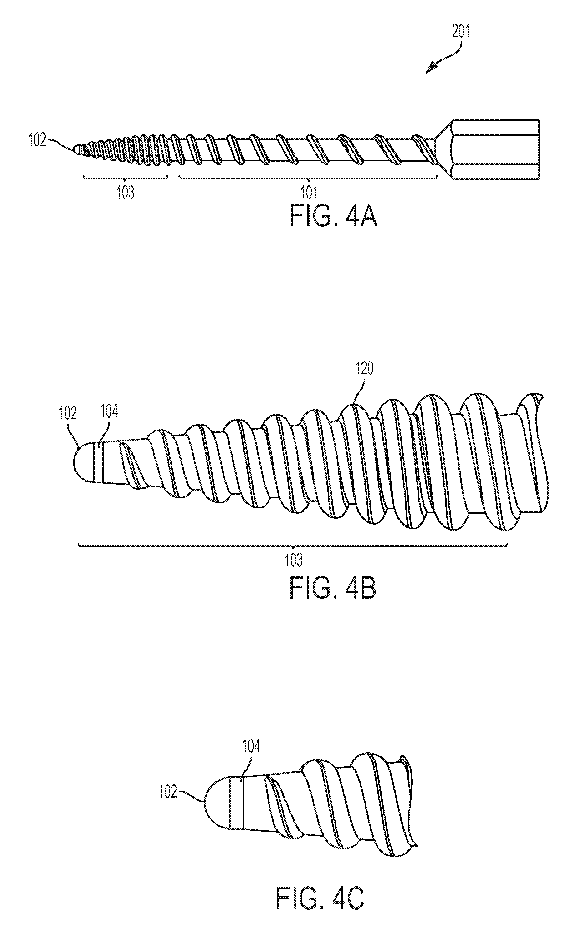
FIG. 4A shows a side view of another embodiment of the invention.
FIG. 4B shows a close-up side view of a distal end of an embodiment of the invention.
FIG. 4C shows a close-up side view of a distal end of an embodiment of the invention.
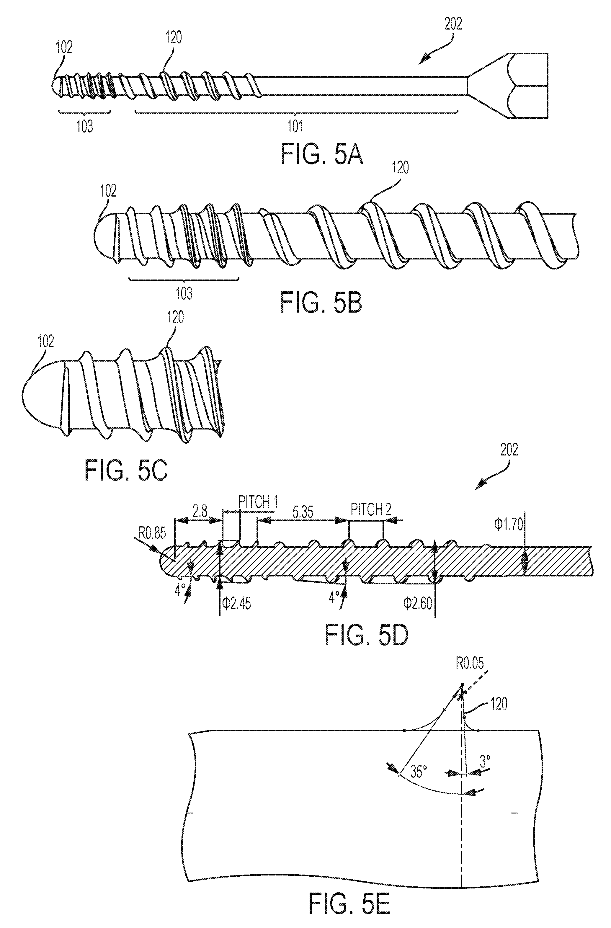
FIG. 5A shows a side view of another embodiment of the invention.
FIG. 5B shows a close-up side view of a distal end of an embodiment of the invention.
FIG. 5C shows a close-up side view of a distal end of an embodiment of the invention.
FIG. 5D shows a cross-section view of an embodiment of the invention.
FIG. 5E shows a close-up side view of a distal end of an embodiment of the invention.
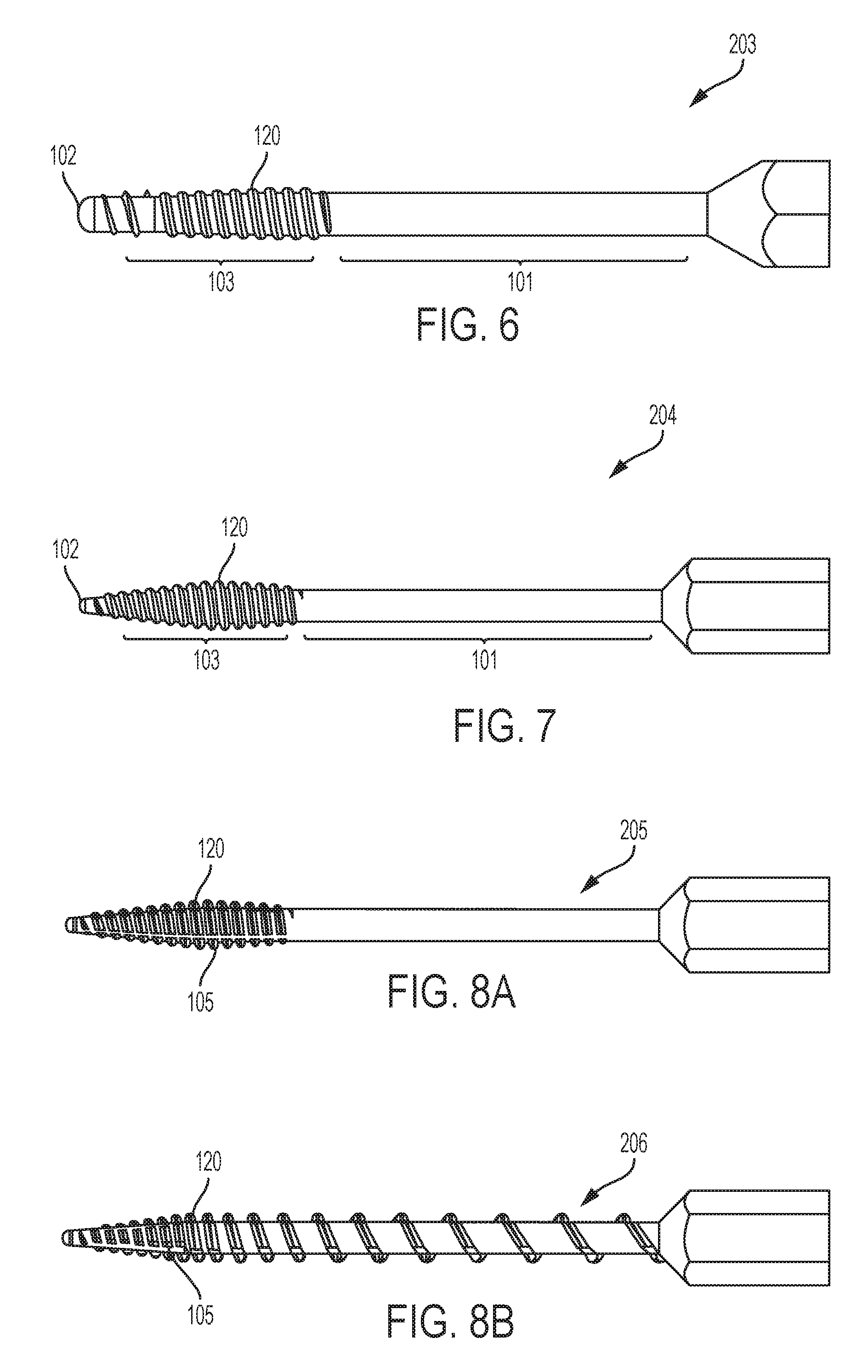
FIG. 6 shows a side view of another embodiment of the invention.
FIG. 7 shows a side view of another embodiment of the invention.
FIG. 8A shows a side view of another embodiment of the invention.
FIG. 8B shows a side view of another embodiment of the invention.
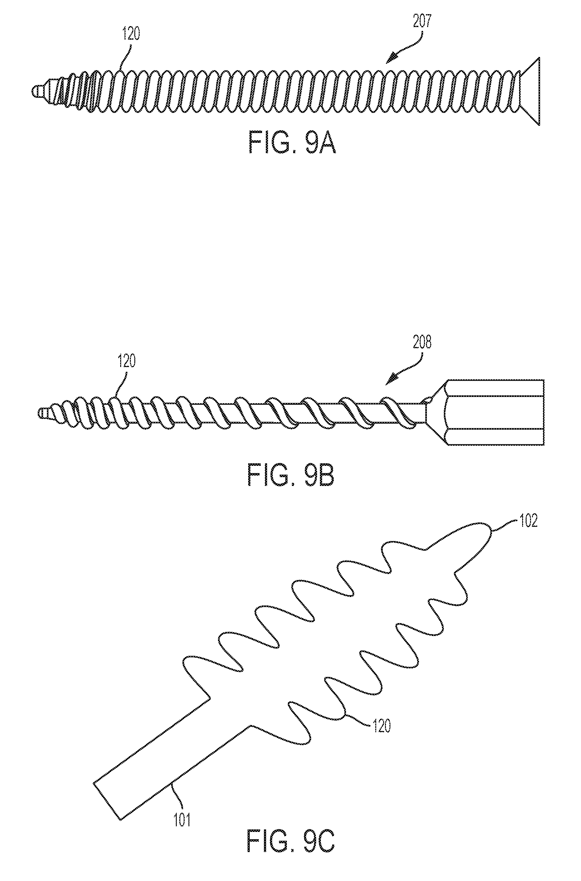
FIG. 9A shows a side view of another embodiment of the invention.
FIG. 9B shows a side view of another embodiment of the invention.
FIG. 9C shows a cross-section of another embodiment of the invention.
FIG. 10A shows a side view of another embodiment of the invention.
FIG. 10B shows a side view of another embodiment of the invention.
FIG. 10C shows a side view of another embodiment of the invention.
FIG. 10D shows a side view of another embodiment of the invention.
FIG. 10E shows a side view of another embodiment of the invention.
FIG. 10F shows a side view of another embodiment of the invention.
FIG. 10G shows a side view of another embodiment of the invention.
FIG. 10H shows a side view of another embodiment of the invention.
FIG. 10I shows a side view of another embodiment of the invention.
FIG. 11A shows a schematic of the threading in an embodiment of the invention.
FIG. 11B shows a schematic of the threading in an embodiment of the invention.
FIG. 12 shows a side view of a bone hole in an embodiment of the invention.
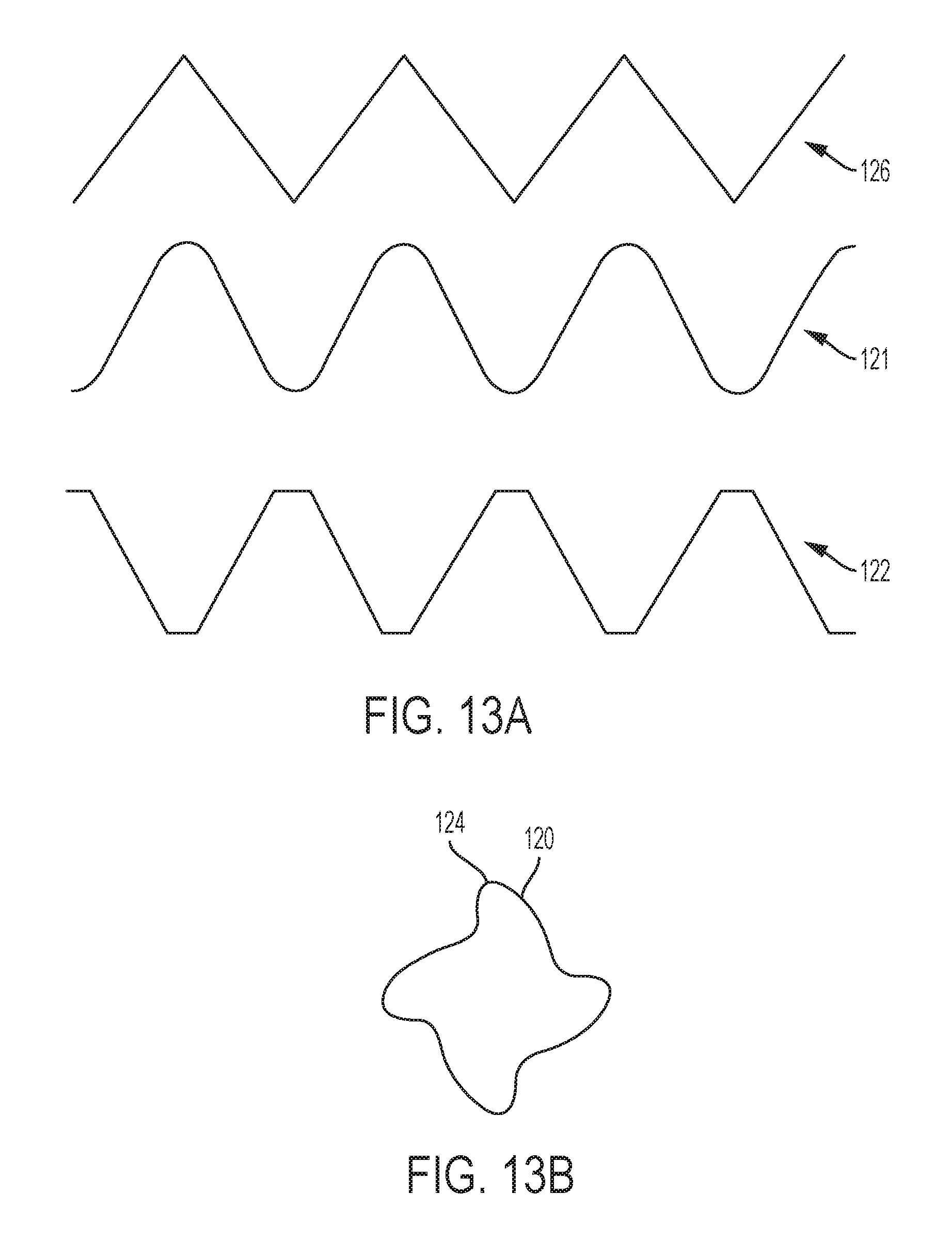
FIG. 13A shows a schematic of the threading in an embodiment of the invention.
FIG. 13B shows a cross-section of the shaft in an embodiment of the invention.
FIG. 14A shows a side view of another embodiment of the invention.
FIG. 14B shows a close-up view of the bone hole in an embodiment of the invention.
FIG. 15A shows a perspective view of the relaxed state of another embodiment of the invention.
FIG. 15B shows a perspective view of the activated state of an embodiment of the invention.
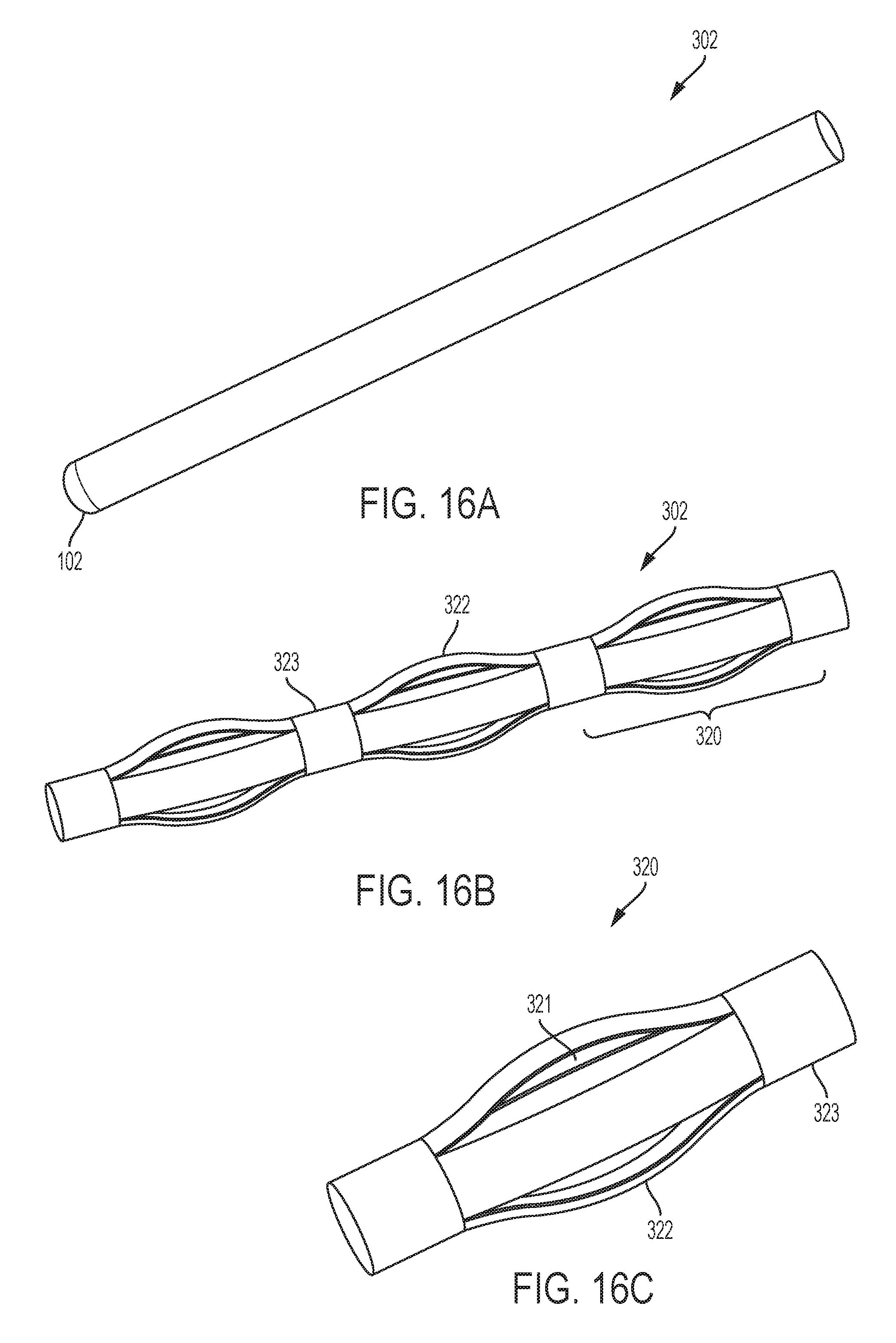
FIG. 16A shows a perspective view of the relaxed state of another embodiment of the invention.
FIG. 16B shows a perspective view of the activated state of an embodiment of the invention.
FIG. 16C shows a close-up perspective view of the activated state of an embodiment of the invention.
DETAILED DESCRIPTION OF THE INVENTION
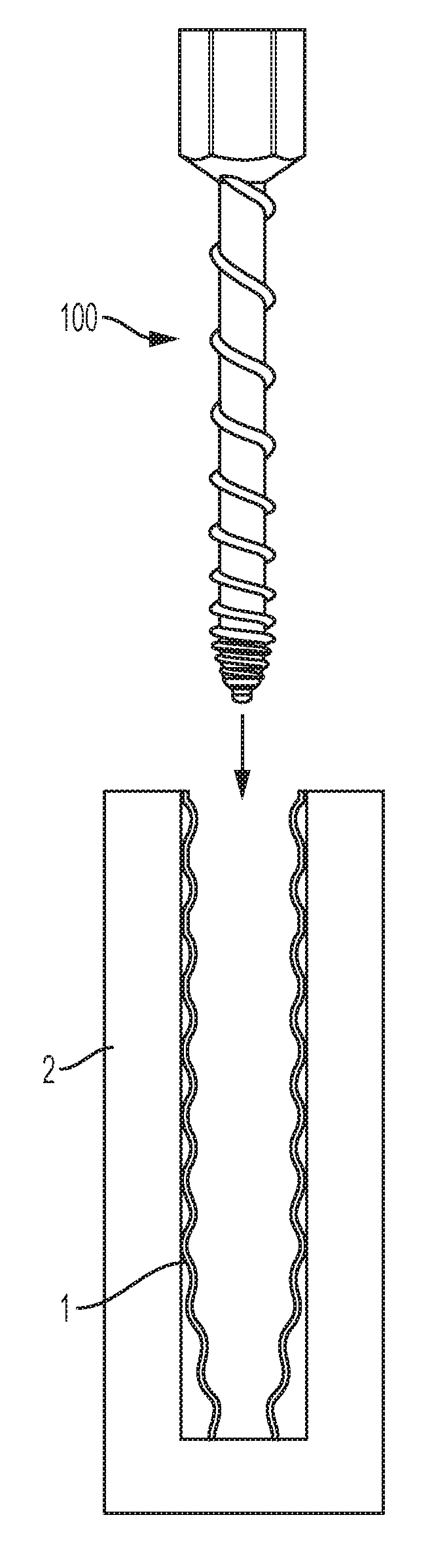
As shown in FIG. 1A, a woven retention device 1 may be placed in a bone hole 3 located within a bone 2. The bone hole 3 may be substantially cylindrical. The woven retention device 1 may initially be in a compressed state, as shown in FIG. 1A. The woven retention device 1 may distribute pressure from the bone screw to multiple points of contact on the exterior surface of the woven retention device 1. The woven retention device 1 may be the woven retention device disclosed in U.S. Pat. No. 8,992,537, which is incorporated by reference herein.
As shown in FIG. 1B, a soft tapping device 100 having soft edges can be designed to run inside the woven retention device 1 after the compressed woven retention device has been placed in the pilot hole. The soft tapping device 100 is a substantially cylindrical insert and can expand the woven retention device 1, as shown in FIG. 1B, and then exit the bone hole 3 so that a self-tapping screw can then enter the expanded woven retention device 1 without damage to the woven retention device 1 because of the soft edges. This allows for the woven retention device 1 to be properly placed within the bone hole 3 in a desired location, with desired dilation. In an embodiment, the soft tapping device 100 may also be designed to be inserted in the bone hole before a woven retention device has been placed in the hole.
As shown in FIG. 2A, the soft tapping device 100 may be inserted into the bone hole 3, such that it passes through the proximal cortex 2a of the bone, and is inserted into the distal cortex 2b of the bone. As shown in FIG. 2B, the soft tapping device 100 includes a head 110, which includes a tool attachment surface 111 that allows for a driving tool to drive the soft tapping device 100 into the bone 2. In an embodiment, the tool attachment surface 111 may be a hex head, for example a Torx hex head. The proximal end of the shaft 101 near the head 110 is not threaded to avoid engagement with the bone and thus reduce friction and back-out resistance. The soft tapping device 100 includes a shaft portion 101, distal end 102, and a distal tip portion 103. The soft tapping device 100 further includes a thread 120 on an outer surface of the soft tapping device 100. The thread 120 may have a radially spiral configuration.
As shown in FIG. 2C, after the soft tapping device 100 is removed from the bone 2 and/or the woven retention device 1, the woven retention device 1 is properly placed within the proximal cortex 2a and distal cortex 2b of the bone 2, and dilated to a particular diameter to accommodate a particular bone screw 4. It is understood that the soft tapping device 100 is shaped to dilate and place the woven retention device 1 without damaging the woven retention device 1.
The thread 120 may be of the type that compresses the bone 2, woven retention device 1, and/or composition in a bone hole 3 as described herein. For example, the thread 120 can make up the soft edges of the soft tapping device, as detailed above. In an embodiment, the soft tapping device 200 does not cut into the bone 2, woven retention device 1 and/or composition. The term "cut" is intended to be used broadly to include the separation of at least a portion of a physical object, into two or more portions, through the application of an acutely directed force. The soft tapping device 100 does not have a cutting thread like a traditional screw or tap. The soft tapping device 100 can have a non-cutting thread provided on the soft tapping device. The application of a tap (as defined broadly as a helical threaded feature) permits a localized dilating of the bone to reduce the radial force needed to compact the bone. As shown in FIG. 2A, the soft tapping device can have a helical thread at the distal portion of the device. The term "non-cutting thread" is intended to be used broadly to include threads that are of the type that preferably do not cut the bone and/or woven device, and that can be non-cutting at the crest of the thread, for example, they can be rounded at the crest of the thread, so as to not cut what it comes into contact with, for example, so as to not cut the bone and/or woven retention device. Non-cutting threads can include threads with no cutting flutes or features such as a longitudinal scallop that is intended to engage bone on its sharp edge to bite into bone. As shown in FIG. 13A, non-cutting thread can also include threads that have blunt, truncated or soft edges at the crest of the thread, whereas cutting threads 126 have triangular or sharp edges at the crest of the thread. These non-cutting threads can include rounded threads 121 and square threads 122 that do not have a sharp peak that can cut into bone. The threads of the soft tapping device can also mimic the thread geometry of the screw that is intended to be inserted into the woven retention device, so the screw follows the thread path created by the soft tapping device. In this way, the bone is dilated in a pattern that is in the shape of the screw pitch. FIG. 13B shows a cross-section of the soft tapping device 100, where threads 120 extend from the core surface of the shaft 101 and have soft edges at the radially outward-most peak or crest 124 of the thread 120.
As shown in FIGS. 3A-C, in a first embodiment, a soft tapping device 200 can be configured, as discussed above, with a shaft portion 101, distal end 102, distal tip portion 103, and thread 120. The edges of the soft tapping device 200 can be in the shape of a center bulging ridged insert where the soft tapping device gradually increases in diameter. In this embodiment, the distal tip 103 includes thread 120 wherein the thread pitch is tight enough to grab the surface, but the thread is somewhat rounded to avoid aggressive cutting. In an embodiment, a soft tapping device 200 with a 2.5 mm shaft diameter may include thread 120 that may have a 1 mm pitch at the distal tip, which increases to an 8 mm pitch at the proximal end of the distal tip. The thread may have a maximum outer diameter of 3.5 mm, and the distal tip may have a 12.degree. taper angle. Further, the thread 120 on the shaft 101 may be coarser with a greater pitch, where the thread pitch may also increase in the proximal direction, and a thread geometry that is even rounder than at the distal tip 103. For example, as shown in FIG. 3D, the thread 120 may be rounded beginning with a radius of 0.2 mm, and height of 0.5 mm at the distal tip 103 and have a 60.degree. thread angle. Contrastingly, as shown in FIG. 3E, the thread 120 at the shaft 101 may be more rounded with a radius of 0.32 mm, and a height of 0.55 mm, and have a 29.degree. thread angle. The thread 120 may have a base 125 and a radially outward-most peak or crest 124. In this embodiment, the distal end 102 may be rounded with a near cortex chamfer leading edge 104 that meets the distal tip 103. This shape of the distal end 102 allows for the soft tapping device 200 to press against the bone 2 without cutting it before the first thread engages.
The soft edges of the soft tapping device 100 can expand the woven retention device and provide a "lead in" at the diameter mismatch areas. Thus, the soft edges of the soft tapping device 100, i.e. the thread 120, can act as a lead in edge that expands the woven retention device. Alternatively, or additionally, soft edges can expand, dilate and/or compress the bone material in the bone hole and provide a "lead in" at the diameter mismatch areas. As shown in FIG. 2A, the distal cortex 2b is compounded by the fact that the woven retention device 1 upon reaching the distal cortex 2b is now constrained.
As shown in FIGS. 4A-C, in an embodiment, the distal tip 103 of a soft tapping device 201 may be tapered directly into the distal end 102, and have a greater taper than the soft tapping device 200 of FIG. 3A. In an embodiment, the thread 120 on the soft tapping device 201 may have the same shape and size on the distal tip 103 and the shaft 101. In an embodiment, the thread 120 on the shaft 101 may have an increasing pitch in the proximal direction. The thread 120 may have a finer pitch at distal tip 103 than the soft tapping device 200 of FIG. 3A. This promotes engagement with the bone 2. In an embodiment, the distal end 102 may have a narrower end that also includes a chamfer 104 between the distal end 102 and the distal tip 103. This rounded shape of the distal end 102 allows for the soft tapping device 201 to slightly pierce bone 2 and allow a smaller diameter thread to engage with the bone before tapering to a larger diameter.
While in some embodiments the soft tapping devices disclosed can be used to prepare the woven retention device for a self-tapping screw to enter the woven retention device, in another embodiment the soft tapping device can be a self-tapping screw. In an embodiment, the soft tapping device 202 may be configured where the distal end 102 and distal tip 103 is not tapered but configured with threads like a cutting tap, where the threads transition to a coarser pitch for the soft tap feature mid-shaft, and there are no threads at the proximal end. As shown in FIG. 5A-D, the distal end 102 and distal tip 103 of the soft tapping device 202 may have a thread 120 that is different than the proximal end and shaft 101. The distal tip 103 has threads that may be sharper (e.g. triangle thread versus square or rounded, as discussed with respect to FIG. 13A) and a smaller pitch to engage the proximal surface of the proximal cortex on starting and the proximal end of the distal cortex surface. This allows the screw tip to self-center and the woven retention device to displace laterally and allows the screw to engage. The proximal end has even softer thread geometry, such as rounded threads and a coarser pitch as discussed above with respect to FIGS. 3A-E. Thus, the soft edges can provide enough expansion to allow a self-tapping screw to be used. As shown in detail in FIGS. 5D-E, in an embodiment the distal tip 103 of soft tapping device 202 may have cortical thread 120 that is scalloped or saw-toothed, to further engage and cut into the bone 2. This allows for the soft tap thread 120 to engage the bone 2 quickly. In an embodiment, as shown in FIG. 5D, the thread 120 has an outer diameter of 2.45 mm at the distal tip 103, and an outer diameter of 2.6 mm at the shaft 101. The distal tip 103 may be 2.8 mm long, and the distal end 102 may have a radius of 0.85 mm. As shown in FIG. 5E, the cortical thread 120 may have a height of 0.375 mm, a 35.degree. angle at the distal face, a 3.degree. angle at the proximal face, and a radius of 0.05 mm at the surface.
As shown in FIG. 6, in an embodiment the distal tip 103 of the soft tapping device 203 may have more rounded thread 120.
As shown in FIG. 7, in an embodiment, the soft tapping device 204 may include a distal tip 103 with a similar pitch and taper as soft tapping device 201 as shown in FIG. 4A. In an embodiment, the shaft 101 of the soft tapping device 204 is smooth, with no threading. This prevents engagement of the soft tapping device 200 with both cortices 2a, 2b at the same time.
Additionally, as shown in FIGS. 8A-B, the soft tap may have longitudinal cleanout grooves 105 along part or all of the length that runs along a longitudinal axis of the soft tapping device 205, 206. This allows for the removal of debris as the soft tapping device 205, 206 moves through the bone so that any bone fragments or various other debris can exit the bone lumen. For example, FIG. 8A shows the embodiment of FIG. 7, but further including longitudinal cleanout grooves 105 along the distal tip 103 of the soft tapping device 205. Similarly, FIG. 8B shows the embodiment of FIG. 4A, but further including longitudinal cleanout grooves 105 along the distal tip 103 of the soft tapping device 206.
As shown in FIG. 9A, an embodiment of the soft tapping device 207 may have thread 120 of consistent shape and size, with an invariable very fine pitch. As shown in FIG. 9B, an embodiment of the soft tapping device 208 may have a rounded thread 120 of consistent shape and size, with a variable pitch. As shown in FIG. 9C, the soft tapping device 100 may also have a shaft 101 that tapers throughout the cylindrical body, before reaching the distal end 102. This may allow for more gentle introduction into the woven retention device 1, while providing a relatively small distal end 102.
As shown in FIGS. 10A-H, embodiments of the soft tapping devices 100 may have an increased ratio of thread height to shaft 101 core, in order to increase engagement with bone 2. In an embodiment, a shaft 101 core diameter may be 1.5 mm. In these embodiments, the soft tapping devices 100 may include a tip as shown in FIG. 5C, using a cortical thread 120 profile. In these embodiments, the taper on the tip may be very low, to allow gradual engagement of these sharper cortical threads. In these embodiments, the shaft portion 101 may have thread 120 with increased pitch with soft rounded threads, to allow for a more aggressive engagement. In an embodiment, a cortical profile thread on the tip may have a pitch of 1 mm and a tip thread outer diameter of either 2.45 or 2.5 mm. It is understood that these various embodiments may be selected by a user to fit an appropriate bone hole or pilot hole.
More specifically, in FIG. 10A, in an embodiment, soft tapping device 209 includes a thread pitch at the shaft portion 101 of 2 mm, with a maximum outer diameter of 2.6 mm. The soft tapping device 209 may have a 38.5 mm working length, measured from the base of the head 110 to the first thread 120. In FIG. 10B, soft tapping device 210 includes a thread pitch at the shaft portion 101 of 2 mm, with a maximum outer diameter of 3.2 mm. The soft tapping device 210 may have a 54.4 mm working length, measured from the base of the head 110 to the first thread 120. In FIG. 10C, soft tapping device 211 includes a thread pitch at the shaft portion 101 of 2 mm, with a maximum outer diameter of 3.5 mm. The soft tapping device 211 may have a 54.4 mm working length, measured from the base of the head 110 to the first thread 120. In FIG. 10D, soft tapping device 212 includes a thread pitch at the shaft portion 101 of 4 mm, with a maximum outer diameter of 2.9 mm. The soft tapping device 212 may have a 58.4 mm working length, measured from the base of the head 110 to the first thread 120. In FIG. 10E, soft tapping device 213 includes a thread pitch at the shaft portion 101 of 4 mm, with a maximum outer diameter of 3.2 mm. The soft tapping device 213 may have a 58.4 mm working length, measured from the base of the head 110 to the first thread 120. In FIG. 10F, soft tapping device 214 includes a thread pitch at the shaft portion 101 of 4 mm, with a maximum outer diameter of 3.5 mm. The soft tapping device 214 may have a 58.4 mm working length, measured from the base of the head 110 to the first thread 120. In FIG. 10G, soft tapping device 215 includes a thread pitch at the shaft portion 101 of 6 mm, with a maximum outer diameter of 2.9 mm. The soft tapping device 215 may have a 67.4 mm working length, measured from the base of the head 110 to the first thread 120. In FIG. 10H, soft tapping device 216 includes a thread pitch at the shaft portion 101 of 6 mm, with a maximum outer diameter of 3.2 mm. The soft tapping device 216 may have a 67.4 mm working length, measured from the base of the head 110 to the first thread 120. In FIG. 10I, soft tapping device 217 includes a thread pitch at the shaft portion 101 of 6 mm, with a maximum outer diameter of 3.5 mm. The soft tapping device 217 may have a 67.4 mm working length, measured from the base of the head 110 to the first thread 120.
As shown in FIGS. 11A-B, in an embodiment the thread 120 may have a path 123 along the soft tapping device 100. As shown in FIG. 11A, at the distal tip 103, the pitch may be 1 mm, where the taper expands from 0.56 mm to 2.4 mm. The thread 120 may have 7 revolutions around the distal tip 103, with an overall length of 7 mm. As shown in FIG. 11B, at the shaft, the pitch may be 1 mm, with a consistent shaft diameter of 2.4 mm. The thread 120 may have 12 revolutions around the shaft 101, with an overall length of 36 mm. In addition, or alternatively, the soft tapping device 100 can be inserted into a bone or pilot hole 3 to compact, compress, expand and/or dilate the bone or pilot hole 3 before insertion of the woven retention device into the bone hole. This soft tapping device 100 can create a bone bed or mantle 5 in the bone material of the bone or pilot hole 3, as shown in FIG. 12, so that when the woven retention device and/or screw is introduced into the bone or pilot hole 3, the bone 2, woven retention device 1 and screw 4 engage reliably. Indeed, a self-tapping screw can be utilized with the woven retention device without damage to the woven retention device.
The soft tapping device 100 can have soft edges that create a complementary impression in the surface of the bone tissue of the bone hole 3. Thus, the complementary impression can provide recesses to the soft edges of the soft tapping device 100 that provide ridges. The soft tapping device 100 can have threads 120 that are the same or different from a screw that could create a track for screw threads to follow or not to follow. In this manner, an interface for screws to cut through for better fixation can be created.
The soft tapping device 100 can be used to push out and/or compress bone in a radial direction of the bone or pilot hole 3. Additionally, or alternatively, the soft tapping device 100 can be used to push out and/or dilate the woven retention device outward, which when the woven retention device 1 is inside the bone hole 3 can similarly push out and/or compress bone out in a direction of the bone or pilot hole 3. This pushed-out bone surface with or without the expanded woven retention device 1 inside the bone hole can be referred to as a layer or mantle, as shown in FIG. 12. The term "mantle" is intended to be interpreted broadly to encompass the bone material in the bone hole 3 that will engage and/or interface with a fastener either directly or indirectly. In one embodiment, the mantle, layer, or composite 5 can be created solely by arranging and/or configuring the existing bone material inside the bone hole 3 utilizing the soft tapping device 100. The process of soft tapping through radially expanding and/or compressing bone material radially outwardly can be repeated one or more times. The bone 2 can be prepared with the bone's own material alone before insertion of a woven retention device 1, the bone's own material and a woven retention device 1 together, e.g., after the woven retention device 1 is inserted in the bone hole 3, and/or with the bone's own material and a third element, feature or substance that can be added, e.g., added to the bone hole and/or the woven retention device. The third item can be a substance as described herein and can be different from the bone tissue and the woven retention device 1.
In an embodiment, a third substance, or an additive different from the woven retention device, can be added to the bone or pilot hole 3 before or after the woven retention device 1 has been inserted into the bone or pilot hole 3. The third substance or additive can facilitate the formation of a mantle 5 of a composite material into which a fastener can then be introduced. The third substance can be bone material, such as autograft or allograft, or bone substitute materials, such as bone cement. The third substance or additive can be a slurry. The slurry can be any of a number of slurries known in the art including calcium phosphate cement slurries. The third substance can be in situ bone, bone material and a woven retention device 1, or bone material, a woven retention device 1, and a slurry. In this manner, an insert, layer or mantle can be created from the inside of the bone or pilot hole 3. This layer or mantle 5 can provide for improved screw fixation and/or for use with various screw types including both self-tapping and non-self-tapping screws.
A bone hole 3 in accordance with the principles of the invention can be formed or created in various non-limiting ways. For example, the bone hole can be formed in a bone either by creating a pilot hole by such means as drilling, tapping, use of an awl or other instruments, or in the form of a screw stripping a pilot hole. Thus, a pilot hole as used herein can refer to a bone hole freshly drilled or stripped by a screw or formed in a bone in other ways. A soft tapping device 100 can compress and/or expand the pilot hole and provide soft edges to the pilot hole based on the exterior surface of the soft tapping device, before or after a woven retention device has been inserted into the pilot hole. A slurry can be added into the pilot hole either with the woven retention device or before insertion of the woven retention device into the pilot hole. The slurry may be a different material from the woven retention device. A fastener, such as a bone screw, can then be inserted to interface with the soft-tap created mantle 5 inside the pilot hole.
The above embodiments envision the woven retention device 1 being inserted into the bone hole 3 and then the soft tapping device 100 is inserted inside the woven retention device 1 to further dilate the hole as well as embed the woven device into the bone, forming a bone-woven device-composite mantel. However, the soft tapping device 100 can be inserted into the bone hole 3 before the woven retention device 1, thus preparing and conditioning the hole. Then the woven device is inserted. This sequence reduces insertion force for the woven device, as well as ensuring the woven device is uniformly radially expanded in the hole. All of the soft tap embodiments disclosed above can be applied in this sequence. In addition, the alternative combination of insertion the soft tapping device, then inserting the woven retention device and then re-inserting the soft tapping device into the woven retention device may provide additional benefit, depending on the condition of the bone, the bone hole size and shape, etc.
Preparing the bone hole for the woven retention device as described above can be accomplished with other configurations of the soft tapping device. The soft tapping device geometry can target a specific location within the bone hole. For example, in FIG. 14A, the soft tapping device can have features that condition the proximal end of the distal cortex only. Shown in the FIG. 14A is a spring-loaded surface 130 that deburrs and/or chamfers the proximal side of the distal cortex bone surface creating a lead-in feature. As shown in FIG. 14B, the spring-loaded deburring tool may create a chamfered hole 6 at the surface of the bone 2, which can create a larger area for the woven retention device 1 or a bone fastener to enter the bone hole 3. This feature can be incorporated with any of the above embodiments of the soft tapping device 100.
Similar to the deburring function described above, in the scenario of inserting the soft tapping device prior to insertion of the woven retention device, the soft tapping device can have more aggressive cutting features or an even separate "hard tap" device can be inserted into the bone hole to core or cut some or all of the bone hole edges to prepare the hole for the woven retention device, as discussed with respect to FIGS. 5A-B, above. This is counterintuitive to the surgeon who works to not remove bone assuming that even a small amount of bone will improve screw retention.
As shown in FIGS. 15A-B and 16A-C, embedding the woven retention device and/or compacting the bone hole surface can be accomplished with other expandable configurations. For example, a soft tapping device 301, 302 may be formed such that the relaxed tap may be inserted into the hole, and activated by compressing the proximal end of the soft tapping device 301, 302. Activating the soft tapping device increases its diameter in total or in a localized way. For example, as shown in FIGS. 15A-B, the "threads" as described above can be protrusions 310 that are expanded radially from the shaft of the soft tapping device, such as a balloon-type device that forms balloon members. FIG. 15A shows a relaxed soft tapping device 301, which is tensioned or deflated such that the shaft surface is smooth and of a uniform diameter. FIG. 15B shows an activated soft tapping device 301, where the soft tapping device 301 is either compressed in a longitudinal direction or inflated, such that the protrusions 310 expand in an outward direction from the shaft of the soft tapping device 301. In this case, the expanded feature is not intended to remove bone but to push/compact bone away from the shaft radially.
Alternatively, other mechanical means can be employed to expand these bone compacting features. For example, there can be singular or multiple expandable features of FIG. 16A-C that are located at various positions along the longitudinal axis, creating radially expanded features along the length. For example, FIG. 16A shows a relaxed soft tapping device 302, which is tensioned such that the shaft surface is smooth and of a uniform diameter. FIG. 16B shows an activated soft tapping device 302, where the soft tapping device 302 is compressed in a longitudinal direction, such that the protrusions 320 expand in an outward direction from the shaft of the soft tapping device 301 to create expanded portions. FIG. 16C shows the activated soft tapping device 302 in more detail, where the surface of the soft tapping device 301 includes slots 321, that form tensioned protrusion slats 322 that can expand in an outward direction from the shaft of soft tapping device 302 to create expanded portions. In this case, the expanded feature is not intended to remove bone but to push/compact bone away from the shaft radially. Other mechanical means besides the two-end constrained leaf spring-like mechanism as shown in FIGS. 15A-B and 16A-C can be used to expand a portion or multiple of portions of the device.
The various embodiments and inventions contemplated here are preferably utilized in with a woven device, for example, a woven retention device. An exemplary woven retention device contemplated for use in accordance with the principles of the invention are described and shown in, for example, U.S. Pat. No. 8,956,394, filed Aug. 5, 2014 and U.S. Pat. No. 8,992,537, filed Sep. 16, 2014, the contents of which are hereby incorporated by reference herein in their entireties.
The embodiments illustrated and discussed in this specification are intended only to teach those skilled in the art how to make and use the invention. In describing embodiments of the invention, specific terminology is employed for the sake of clarity. However, the invention is not intended to be limited to the specific terminology so selected. The above-described embodiments of the invention may be modified or varied, without departing from the invention, as appreciated by those skilled in the art in light of the above teachings. It is therefore to be understood that, within the scope of the claims and their equivalents, the invention may be practiced otherwise than as specifically described.
* * * * *
References
-
acesurgical.com/bone-grafting/graft-holding-mesh-foils/mic
-
cousin-biotech.com/uk/produit.php?idrubrique=16&idspecialite=35&idproduit=81
-
bioretec.com/products/pro_orthotrauma/activascrew-cannulated/surgical-technique.php
-
conmed.com/products/knee-fixation.php
-
goremedical.com/stp
-
openprosthetics.org/suspension
-
ethicon.com/healthcare-professionals/products/tissue-hernia/mesh/vicryl-polyglactin-910-woven-mesh
D00000
D00001
D00002
D00003
D00004
D00005
D00006
D00007
D00008
D00009
D00010
D00011
D00012

D00013
XML
uspto.report is an independent third-party trademark research tool that is not affiliated, endorsed, or sponsored by the United States Patent and Trademark Office (USPTO) or any other governmental organization. The information provided by uspto.report is based on publicly available data at the time of writing and is intended for informational purposes only.
While we strive to provide accurate and up-to-date information, we do not guarantee the accuracy, completeness, reliability, or suitability of the information displayed on this site. The use of this site is at your own risk. Any reliance you place on such information is therefore strictly at your own risk.
All official trademark data, including owner information, should be verified by visiting the official USPTO website at www.uspto.gov. This site is not intended to replace professional legal advice and should not be used as a substitute for consulting with a legal professional who is knowledgeable about trademark law.