Systems and methods for reducing vehicle valve degradation
Leone , et al. Fe
U.S. patent number 10,550,776 [Application Number 16/188,838] was granted by the patent office on 2020-02-04 for systems and methods for reducing vehicle valve degradation. This patent grant is currently assigned to Ford Global Technologies, LLC. The grantee listed for this patent is Ford Global Technologies, LLC. Invention is credited to Aed M. Dudar, Thomas Leone, Kenneth Miller.


View All Diagrams
| United States Patent | 10,550,776 |
| Leone , et al. | February 4, 2020 |
Systems and methods for reducing vehicle valve degradation
Abstract
Methods and systems are provided for reducing degradation and issues related to noise, vibration and harshness (NVH) for a canister purge valve configured to regulate a flow of fuel vapors from a fuel vapor canister to an engine in response to a request to purge the fuel vapor canister of fuel vapors. In one example, a method may include purging the fuel vapor canister by synchronizing a timing of opening and closing events of the canister purge valve to correspond with instances where a pressure difference across the canister purge valve is lower as compared to higher in terms of pressure oscillations across the canister purge valve during the purging. In this way, higher loads and stress on the canister purge valve may be avoided, thus reducing degradation and NVH issues.
| Inventors: | Leone; Thomas (Ypsilanti, MI), Dudar; Aed M. (Canton, MI), Miller; Kenneth (Pinckney, MI) | ||||||||||
|---|---|---|---|---|---|---|---|---|---|---|---|
| Applicant: |
|
||||||||||
| Assignee: | Ford Global Technologies, LLC
(Dearborn, MI) |
||||||||||
| Family ID: | 69230107 | ||||||||||
| Appl. No.: | 16/188,838 | ||||||||||
| Filed: | November 13, 2018 |
| Current U.S. Class: | 1/1 |
| Current CPC Class: | F02D 41/004 (20130101); B60K 15/03519 (20130101); F02D 41/0045 (20130101); B60K 15/03504 (20130101); F02M 25/0836 (20130101); F02M 25/089 (20130101); B60K 2015/03514 (20130101); B60K 2015/03296 (20130101); F02D 2200/0406 (20130101); F02D 41/123 (20130101); B60K 2015/03302 (20130101); F02D 41/062 (20130101); F02N 11/0807 (20130101) |
| Current International Class: | F02M 1/00 (20060101); F02M 25/08 (20060101); B60K 15/035 (20060101); F02D 41/00 (20060101); B60K 15/03 (20060101) |
| Field of Search: | ;123/516-520 |
References Cited [Referenced By]
U.S. Patent Documents
| 4630581 | December 1986 | Shibata |
| 5031450 | July 1991 | Nakaniwa et al. |
| 5351193 | September 1994 | Poirier et al. |
| 5413082 | May 1995 | Cook et al. |
| 5553595 | September 1996 | Nishioka |
| 5571003 | November 1996 | Tuckey |
| 5609135 | March 1997 | Ogawa et al. |
| 5649687 | July 1997 | Rosas et al. |
| 6085731 | July 2000 | Duty |
| 6138655 | October 2000 | Kerns et al. |
| 6234141 | May 2001 | Kerns et al. |
| 6237328 | May 2001 | Kerns |
| 6257194 | July 2001 | Kerns et al. |
| 6269793 | August 2001 | Russ et al. |
| 6763298 | July 2004 | Boggs et al. |
| 7182072 | February 2007 | Clemens |
| 7930087 | April 2011 | Gibson et al. |
| 8099947 | January 2012 | Makki et al. |
| 8375701 | February 2013 | Lupescu et al. |
| 8438837 | May 2013 | Hermansson et al. |
| 8447494 | May 2013 | Wang et al. |
| 8775011 | July 2014 | Makki et al. |
| 8800356 | August 2014 | Makki et al. |
| 9243592 | January 2016 | Dudar et al. |
| 9739244 | August 2017 | Dudar |
| 9850832 | December 2017 | Dudar |
| 9932937 | April 2018 | Jentz |
| 10012183 | July 2018 | Dudar |
| 2013/0164644 | June 2013 | Noh et al. |
| 2014/0067235 | March 2014 | Banker et al. |
| 2014/0130781 | May 2014 | Jentz |
| 2014/0366508 | December 2014 | Ulrey et al. |
| 2015/0285170 | October 2015 | Nanba |
| 2016/0369713 | December 2016 | Pursifull |
Other References
|
Dudar, A. et al., "Systems and Methods for Onboard Canister Purge Valve Flow Mapping," U.S. Appl. No. 15/987,028, filed May 23, 2018, 130 pages. cited by applicant . Dudar, A., "Systems and Methods for Onboard Canister Purge Valve Flow Mapping," U.S. Appl. No. 15/987,046, filed May 23, 2018, 130 pages. cited by applicant . Dudar, A. "Systems and Methods for Reducing Vehicle Valve Degradation," U.S. Appl. No. 16/188,910, filed Nov. 13, 2018, 116 pages. cited by applicant . Dudar, A. et al., "Systems and Methods for Reducing Vehicle Valve Degradation," U.S. Appl. No. 16/188,980, filed Nov. 13, 2018, 115 pages. cited by applicant . Dudar, A. et al., "Systems and Methods for Reducing Vehicle Valve Degradation," U.S. Appl. No. 16/189,186, filed Nov. 13, 2018, 118 pages. cited by applicant. |
Primary Examiner: Kwon; John
Attorney, Agent or Firm: Brumbaugh; Geoffrey McCoy Russell LLP
Claims
The invention claimed is:
1. A method comprising: purging a fuel vapor canister that captures and stores fuel vapors from a fuel system of a vehicle by synchronizing a timing of opening and closing events of a canister purge valve to correspond with instances where a pressure difference across the canister purge valve is lower as compared to higher in terms of pressure oscillations across the canister purge valve during purging the fuel vapor canister.
2. The method of claim 1, further comprising adjusting the timing of the opening and the closing events of the canister purge valve in response to changes in the pressure oscillations across the canister purge valve during purging the fuel vapor canister.
3. The method of claim 1, further comprising controlling a duty cycle of the canister purge valve while synchronizing the timing of the opening and the closing events of the canister purge valve to correspond with the instances where the pressure difference across the canister purge valve is lower as compared to higher in terms of the pressure oscillations.
4. The method of claim 1, wherein the pressure oscillations are a function of at least operating conditions of an engine that receives purge gasses from the fuel vapor canister and further comprising: determining a frequency, a phase, and an amplitude of the pressure oscillations across the canister purge valve in order to synchronize the timing of the opening and the closing events of the canister purge valve to correspond with the instances where the pressure difference across the canister purge valve are lower as compared to higher in terms of the pressure oscillations.
5. The method of claim 4, wherein determining the frequency, the phase and the amplitude of the pressure oscillations includes mapping the pressure oscillations based on one or more of at least an engine speed, an engine load, a timing of opening and/or closing of intake and/or exhaust valves of the engine, and an ambient temperature.
6. The method of claim 4, wherein determining the frequency, the phase and the amplitude of the pressure oscillations is based at least in part on feedback from a pressure sensor at the canister purge valve.
7. The method of claim 4, wherein determining the frequency, the phase, and the amplitude of the pressure oscillations is based at least in part on a difference between an engine intake pressure and a fuel system pressure with the fuel system coupled to atmosphere, corrected for an offset that is modelled as a function of a restriction of a buffer section of the fuel vapor canister.
8. The method of claim 1, wherein synchronizing the timing of the opening and the closing events of the canister purge valve to correspond with the instances where the pressure difference across the canister purge valve is lower as compared to higher in terms of the pressure oscillations across the canister purge valve further comprises controlling a pulse width modulation signal to the canister purge valve based on the pressure oscillations across the canister purge valve.
9. The method of claim 1, wherein synchronizing the timing of the opening and the closing events of the canister purge valve to correspond with the instances where the pressure difference across the canister purge valve is lower as compared to higher in terms of the pressure oscillations across the canister purge valve improves durability and reduces issues related to noise, vibration and harshness of the canister purge valve.
10. The method of claim 1, wherein synchronizing the timing of the opening and the closing events of the canister purge valve to correspond with the instances where the pressure difference across the canister purge valve is lower as compared to higher in terms of the pressure oscillations across the canister purge valve further comprises controlling the canister purge valve to open and/or close within a threshold time duration in relation to the pressure oscillations across the canister purge valve, the threshold time duration corresponding to when the pressure difference is lower as compared to higher in terms of the pressure oscillations across the canister purge valve.
11. A method for a vehicle comprising: reducing degradation and issues related to noise, vibration and harshness of a canister purge valve by timing opening and closing events of the canister purge valve to coincide with when a pressure difference across the canister purge valve is lower than a threshold pressure difference in terms of pressure oscillations across the canister purge valve while purging a fuel vapor canister of fuel vapors.
12. The method of claim 11, wherein the threshold pressure difference is determined as a function of the pressure oscillations across the canister purge valve; and wherein the threshold pressure difference is updated as the pressure oscillations change during the course of purging the fuel vapor canister of fuel vapors.
13. The method of claim 12, further comprising determining a frequency, a phase and an amplitude of the pressure oscillations across the canister purge valve and controlling a pulse width modulation signal to the canister purge valve in order to synchronize the timing of the opening and the closing of the canister purge valve to coincide with when the pressure difference across the canister purge valve is lower than the threshold pressure difference in terms of the pressure oscillations across the canister purge valve.
14. The method of claim 11, wherein reducing degradation and issues related to noise, vibration and harshness of the canister purge valve further comprises: commanding the canister purge valve fully open without first commanding lower percentage duty cycles in response to a request for purging the fuel vapor canister, under select vehicle operating conditions.
15. The method of claim 14, wherein the select vehicle operating conditions includes a remote start event of an engine of the vehicle, where the vehicle is indicated to be unoccupied and where an exhaust catalyst is at or above an operating temperature of the exhaust catalyst.
16. The method of claim 14, wherein the select vehicle operating conditions includes a deceleration fuel shut-off event where fueling to an engine of the vehicle is shut off but where intake and exhaust valves of the engine continue to open and close, and where an exhaust catalyst is at or above an operating temperature of the exhaust catalyst.
17. A system for a vehicle, comprising: a canister purge valve positioned in a purge line fluidically coupling a fuel vapor canister to an intake of an engine; and a controller with computer readable instructions stored on non-transitory memory that when executed, cause the controller to: receive a request to purge the fuel vapor canister of fuel vapors to the engine; in a first condition, control the canister purge valve in a first mode to synchronize a timing of opening and closing of the canister purge valve as a function of pressure oscillations across the canister purge valve; and in a second condition, control the canister purge valve in a second mode that includes commanding the canister purge valve fully open without first commanding lower percentage duty cycles in response to the request for purging the fuel vapor canister.
18. The system of claim 17, further comprising an exhaust catalyst positioned in an exhaust of the engine; and wherein the controller stores further instructions to control the canister purge valve in the first mode or the second mode provided that a temperature of the exhaust catalyst is at or above a threshold temperature.
19. The system of claim 17, further comprising one or more of seat load cells, door sensing technology and/or onboard cameras for indicating occupancy of the vehicle; fuel injectors for fueling the engine; and wherein the controller stores further instructions to control the canister purge valve in the second mode in response to an indication of a remote start of the engine where the vehicle is further indicated to be unoccupied, or in response to an indication of a deceleration fuel shut off event where fuel to the engine is discontinued while engine intake and engine exhaust valves continue to operate.
20. The system of claim 17, further comprising: a crankshaft position sensor; a mass air flow sensor positioned in the intake of the engine; a throttle positioned in the intake of the engine; an ambient air temperature sensor; position sensors for engine intake and exhaust valves; an intake temperature sensor; a manifold air pressure sensor positioned in the intake; a fuel tank temperature sensor positioned in a fuel system; wherein the controller stores further instructions to map a frequency, a phase and an amplitude of the pressure oscillations across the canister purge valve based on data retrieved from a plurality of two or more of the crankshaft position sensor, the mass air flow sensor, the ambient air temperature sensor, the position sensors for the engine intake and exhaust valves, the intake temperature sensor, the manifold air pressure sensor and/or the fuel tank temperature sensor; and wherein controlling the canister purge valve in the first mode to synchronize the timing of opening and closing of the canister purge valve as a function of pressure oscillations across the canister purge valve includes controlling a pulse width modulation signal to the canister purge valve as a function of the frequency, the phase and the amplitude of the pressure oscillations, such that opening and closing events of the canister purge valve occur at times in terms of the pressure oscillations where a pressure difference across the canister purge valve is less than a threshold pressure difference, where the threshold pressure difference is set as a function of the frequency, the phase and the amplitude of the pressure oscillations.
Description
FIELD
The present description relates generally to methods and systems for controlling one or more valves configured to regulate a flow of fuel vapors in a vehicle fuel system and/or evaporative emissions system, the controlling a function of engine operating conditions.
BACKGROUND/SUMMARY
Some automotive fuels may exhibit rapid evaporation in response to diurnal variations in ambient temperature. Emissions resulting from such vapors may be reduced in automotive applications via evaporative emission control systems (EVAP), The EVAP systems include a fuel vapor storage canister containing adsorbent, such as carbon, that traps those fuel vapors and feeds them back to the vehicle's engine for combustion during canister purging operations, thus, reducing evaporative emissions from the vehicle and improving fuel economy.
In a canister purge operation, a canister purge valve (CPV) coupled between the engine intake and the fuel canister may be duty cycled, allowing for intake manifold vacuum to be applied to the fuel canister. On a boosted engine, that vacuum draw may be supplied via an ejector during boosted operation. Simultaneously, a canister vent valve coupled between the fuel canister and atmosphere can be opened, allowing for fresh air to enter the canister. Further, in some examples, a fuel tank isolation valve coupled between the fuel tank and the fuel canister may be closed to reduce the flow of fuel vapors from the fuel tank to the engine. This configuration facilitates desorption of stored fuel vapors from the adsorbent material in the canister, regenerating the adsorbent material for further fuel vapor adsorption.
Canister purge valves in EVAP systems that are duty cycled may have durability issues. Furthermore, opening and closing the CPV when there is a high pressure difference across the valve may result in the CPV experiencing higher loads and stresses as compared to situations where there is a lower pressure difference across the valve. Depending on the frequency and duty cycle of the purge valve opening and closing during pulsed flow control compared to engine firing frequency, more or less openings can occur at varying pressure differences, thus leading to unequal degradation of the valve due to the higher loads and stresses.
The inventors herein have recognized the above-mentioned issues and desires, and have developed systems and methods to at least partially address them. In one example, a method comprises purging a fuel vapor canister that captures and stores fuel vapors from a fuel system of a vehicle by synchronizing a timing of opening and closing events of a canister purge valve to correspond with instances where a pressure difference across the canister purge valve is lower as compared to higher in terms of pressure oscillations across the canister purge valve during purging the fuel vapor canister. In this way, issues related to durability of the CPV may be reduced or avoided.
In one example of the method, the method may further comprise adjusting the timing of the opening and the closing events of the canister purge valve in response to changes in the pressure oscillations across the canister purge valve during purging the fuel vapor canister.
As another example of the method, the method may further comprise controlling a duty cycle of the canister purge valve while synchronizing the timing of the opening and the closing events of the canister purge valve to correspond with the instances where the pressure difference across the canister purge valve is lower as compared to higher in terms of the pressure oscillations.
As another example, the pressure oscillations are a function of at least operating conditions of an engine that receives purge gasses from the fuel vapor canister. In such an example, the method may include determining a frequency, a phase, and an amplitude of the pressure oscillations across the canister purge valve in order to synchronize the timing of the opening and the closing events of the canister purge valve to correspond with the instances where the pressure difference across the canister purge valve are lower as compared to higher in terms of the pressure oscillations. In such a method, determining the frequency, the phase and the amplitude of the pressure oscillations may include mapping the pressure oscillations based on one or more of at least an engine speed, an engine load, a timing of opening and/or closing of intake and/or exhaust valves of the engine, and an ambient temperature. In another example, determining the frequency, the phase and the amplitude of the pressure oscillations may be based at least in part on feedback from a pressure sensor at the canister purge valve. In yet another example, determining the frequency, the phase, and the amplitude of the pressure oscillations may be based at least in part on a difference between an engine intake pressure and a fuel system pressure with the fuel system coupled to atmosphere, corrected for an offset that may be modelled as a function of a restriction of a buffer section of the fuel vapor canister.
In another example of the method, synchronizing the timing of the opening and the closing events of the canister purge valve to correspond with the instances where the pressure difference across the canister purge valve is lower as compared to higher in terms of the pressure oscillations across the canister purge valve may further comprise controlling a pulse width modulation signal to the canister purge valve based on the pressure oscillations across the canister purge valve.
In still another example of the method, synchronizing the timing of the opening and the closing events of the canister purge valve to correspond with the instances where the pressure difference across the canister purge valve is lower as compared to higher in terms of the pressure oscillations across the canister purge valve improves durability and reduces issues related to noise, vibration and harshness of the canister purge valve.
In yet another example of the method, synchronizing the timing of the opening and the closing events of the canister purge valve to correspond with the instances where the pressure difference across the canister purge valve is lower as compared to higher in terms of the pressure oscillations across the canister purge valve further comprises controlling the canister purge valve to open and/or close within a threshold time duration in relation to the pressure oscillations across the canister purge valve, the threshold time duration corresponding to when the pressure difference is lower as compared to higher in terms of the pressure oscillations across the canister purge valve.
The above advantages and other advantages, and features of the present description will be readily apparent from the following Detailed Description when taken alone or in connection with the accompanying drawings.
It should be understood that the summary above is provided to introduce in simplified form a selection of concepts that are further described in the detailed description. It is not meant to identify key or essential features of the claimed subject matter, the scope of which is defined uniquely by the claims that follow the detailed description. Furthermore, the claimed subject matter is not limited to implementations that solve any disadvantages noted above or in any part of this disclosure.
BRIEF DESCRIPTION OF THE DRAWINGS
FIG. 1 shows a schematic description of an engine including a fuel system, and an evaporative emissions system.
FIG. 2 graphically illustrates pressure oscillations across a canister purge valve as a function of engine operating conditions.
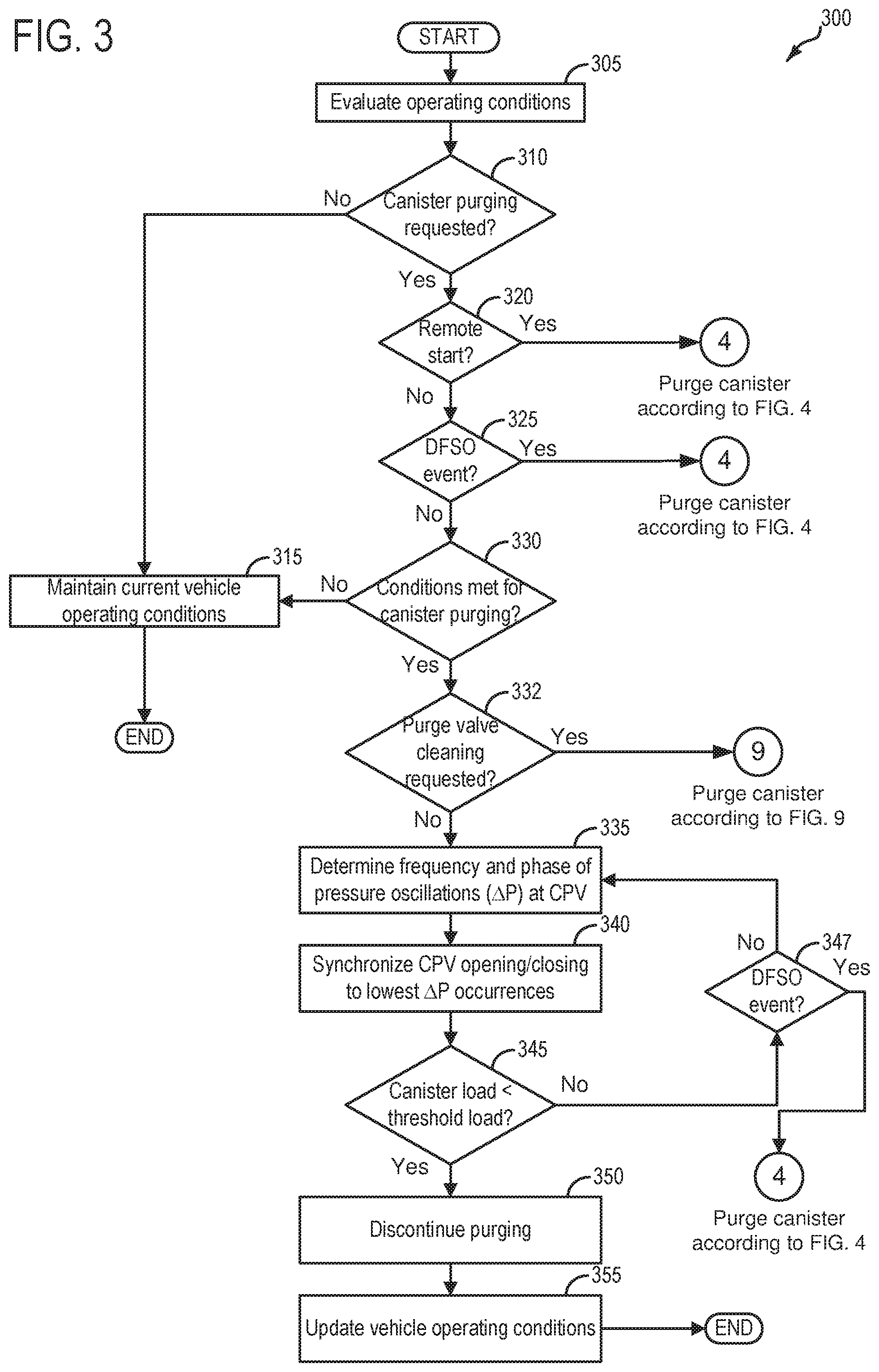
FIG. 3 depicts a high-level example method for selecting an appropriate strategy to conduct a canister purging event to reduce wear and tear on a canister purge valve.
FIG. 4 depicts a high-level example method for conducting a canister purging operation under conditions of a remote engine start event and/or a deceleration fuel shut-off event.
FIG. 5A depicts an example timeline for ramping up a duty cycle of a canister purge valve during a canister purging event, where a pulse width modulation (PWM) signal to the CPV is controlled as a function of pressure oscillations across the CPV.
FIG. 5B depicts an example timeline illustrating a timing of voltage pulses applied to the CPV, where the CPV comprises a solenoid valve, and where a frequency of valve pulsing is equal to or less than a frequency of pressure oscillations across the CPV.
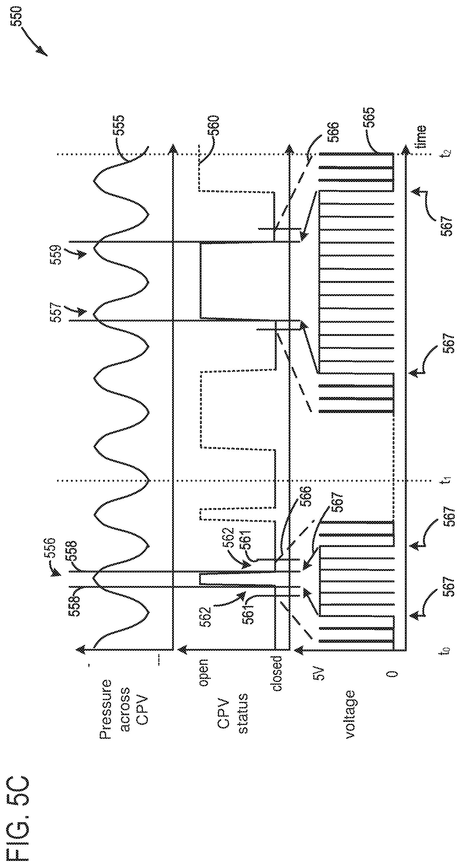
FIG. 5C depicts an example timeline illustrating a timing of voltage pulses applied to the CPV as in FIG. 5B, where a frequency of valve pulsing is greater than a frequency of pressure oscillations across the CPV.
FIG. 5D depicts an example timeline illustrating a timing of voltage pulses applied to the CPV as in FIGS. 5B-5C, where a frequency of valve pulsing is lower than a frequency of pressure oscillations across the CPV, and where CPV duty cycle changes without a corresponding change in frequency of the valve pulsing.
FIG. 6 depicts an example timeline for conducting canister purging according to the methodology depicted at FIGS. 3-4.
FIG. 7 depicts a high-level example method for conducting a fuel tank depressurization routine that reduces wear and tear on a fuel tank pressure control valve (TPCV).
FIG. 8 depicts an example timeline for conducting the fuel tank depressurization routine according to the method depicted at FIG. 7.
FIG. 9 depicts a high-level example method that continues from FIG. 3, and includes conducting a cleaning operation on the CPV during purging of the canister.
FIG. 10 depicts a high-level example method for determining whether the cleaning routine depicted at FIG. 9 was successful.
FIG. 11 depicts an example timeline for conducting the CPV cleaning operation according to the method of FIG. 9.
FIG. 12 depicts an example timeline for verifying whether the CPV cleaning routine was successful, according to the method of FIG. 10.
DETAILED DESCRIPTION
The following description relates to systems and methods for reducing degradation of one or more valves that control flow of fuel vapors in a vehicle fuel system and/or evaporative emissions system. In one example the valve is a canister purge valve (CPV) positioned in a purge line coupling a fuel vapor canister to engine intake. In another example the valve is a fuel tank pressure control valve (TPCV) that is used for depressurizing the fuel tank under particular vehicle operating conditions. The systems and methods discussed herein are particularly applicable to hybrid electric vehicles, such as the hybrid vehicle system of FIG. 1. Specifically, a fuel vapor canister traps and stores fuel vapors from a vehicle fuel system, and at a later time, the contents of the canister are purged to the engine where the stored fuel vapors are combusted. To purge the canister, the CPV can be pulse width modulated (PWM) to open and close at a particular frequency. However, pressure differences across the CPV may affect the forces and stresses for each opening and closing event of the CPV. As one side of the CPV is connected to engine intake, pressure oscillations during canister purging events stemming from engine operation (e.g. intake and exhaust valve opening/closing, phasing/timing changes when variable camshaft timing is used to alter intake and/or exhaust valve timing, etc.) may result in situations where the CPV is commanded open at times when pressure across the CPV is greater as compared to lower in terms of the pressure oscillations. This may disproportionately adversely impact CPV function (e.g. lead to degradation) as compared to CPV opening/closing events when pressure across the CPV is lower in terms of the pressure oscillations. Furthermore, when the CPV is opened/closed when pressure differences across the CPV are greater (as compared to lower) in terms of the pressure oscillations, issues related to undesirable noise, vibration and harshness (NVH) may be increased. Similar issues may arise in duty cycling the TPCV to relieve pressure. For example, if the TPCV is controlled to open and/or close when pressure differences are high as compared to low in terms of pressure oscillations across the TPCV during fuel tank depressurization routines, then TPCV degradation may occur at a faster rate than if the TPCV is controlled to open and/or close when the pressure differences are low as compared to high. Thus, it is herein recognized that it may be desirable to control the PWM signal to the CPV or TPCV such that opening and closing events of are timed to coincide with lower pressure differences across the valve in terms of the pressure oscillations. Depicted at FIG. 2 is an example illustration of such pressure oscillations across a CPV during a canister purging operation, highlighting points along the pressure oscillation wave where the CPV may be opened/closed in order to reduce degradation of the CPV and to reduce NVH issues.
FIG. 3 depicts an example method for selecting whether to time opening/closing of the CPV with the points of a pressure oscillation wave that comprise the lower pressure differences across the CPV in terms of the pressure oscillations as compared to greater pressure differences, or to take a different approach. Specifically, there may be some circumstances of vehicle operation where instead of timing the CPV opening/closing events as discussed, it may instead be desirable to purge the canister immediately with a 100% duty cycle, which may greatly reduce opportunities for degradation of the CPV and which additionally may aggressively purge the canister which may be desirable for hybrid vehicles with limited engine run time. Such circumstances include remote engine start events and deceleration fuel shut off (DFSO) events, and it will be discussed in further detail below as to why such conditions may be amenable to aggressively purging the canister with a 100% duty cycle. Thus, if it is determined that the vehicle is in the process of a remote start event or a DFSO mode, then the method of FIG. 4 may be used to purge the canister.
FIG. 5A depicts an example timeline illustrating how, depending on the pressure oscillations across the CPV, a purge ramp may be conducted. In other words, FIG. 5A depicts how duty cycle and frequency of opening/closing events of the CPV may be adjusted or controlled in order to increase an amount of vapors purged to the engine intake during a purge event, while maintaining the CPV opening/closing events to coincide with low pressure events in terms of the pressure oscillations. The CPV may be a solenoid-actuated valve, and accordingly, FIG. 5B depicts how voltage pulses to the CPV may be controlled in order to time CPV opening/closing events with low pressure points in terms of the pressure oscillations across the CPV during a purging event. In some examples, the frequency of CPV pulsing may be greater than a frequency of pressure oscillations across the CPV, as depicted at FIG. 5C. Alternatively, another example includes a situation where the frequency of CPV pulsing may be less than the frequency of pressure pulsations across the CPV, as depicted at FIG. 5D. An example timeline for conducting a canister purging operation according to the methods of FIGS. 3-4, is depicted at FIG. 6.
As discussed above, in other examples it may be desirable to control a TPCV in similar fashion as that discussed in terms of the CPV, to reduce valve degradation during fuel tank depressurization events. A method for doing so is depicted at FIG. 7. FIG. 8 depicts an example timeline for conducting a fuel tank depressurization, where the TPCV is timed to open and close at times corresponding to low pressure differences across the TPCV in terms of pressure oscillations across the TPCV, according to the method of FIG. 7.
While controlling CPV opening and closing events to coincide with low pressure differences across the CPV during purging of the canister may reduce degradation, there may be circumstances where the CPV is determined to be not sealing properly when closed. In such a case, it may be desirable to time CPV opening and closing events to coincide with high pressure differences across the CPV in terms of pressure oscillations during purging the canister. In this way, whatever is causing the CPV to not seal properly when closed (e.g. carbon pellets, dust, fibers, cardboard, etc.), may be dislodged, resulting in the CPV once again sealing properly. Accordingly, a method for conducting a CPV cleaning operation is depicted at FIG. 9. After conducting the CPV cleaning operation, the method of FIG. 10 may be used to ascertain whether the CPV cleaning routine successfully restored the ability of the CPV to seal properly or as expected, when commanded closed. A timeline for conducting the CPV cleaning operation according to the method of FIG. 9, is depicted at FIG. 11. A timeline for ascertaining whether such a CPV cleaning operation resulted in the ability of the CPV to seal properly according to the method of FIG. 10, is depicted at FIG. 12.
Turning now to FIG. 1, a schematic depiction of a hybrid vehicle system 6 is presented that can derive propulsion power from engine system 10 and/or an on-board energy storage device, such as a battery system (see below). An energy conversion device, such as a generator (see below), may be operated to absorb energy from vehicle motion and/or engine operation, and then convert the absorbed energy to an energy form suitable for storage by the energy storage device. Engine system 10 may comprise a multi-cylinder internal combustion engine, which may be included in a propulsion system of an automotive vehicle. Engine 10 may be controlled at least partially by a control system including controller 12 and by input from a vehicle operator 130 via an input device 132. In this example, input device 132 includes an accelerator pedal and a pedal position sensor 134 for generating a proportional pedal position signal PP.
Engine 10 may include a lower portion of the engine block, indicated generally at 26, which may include a crankcase 28 encasing a crankshaft 30 with oil well 32 positioned below the crankshaft. An oil fill port 29 may be disposed in crankcase 28 so that oil may be supplied to oil well 32. Oil fill port 29 may include an oil cap 33 to seal oil fill port 29 when the engine is in operation. A dip stick tube 37 may also be disposed in crankcase 28 and may include a dipstick 35 for measuring a level of oil in oil well 32. An oil temperature sensor 51 may be included in crankcase 28, and may monitor temperature of oil in oil well 32. In addition, crankcase 28 may include a plurality of other orifices for servicing components in crankcase 28. These orifices in crankcase 28 may be maintained closed during engine operation so that a crankcase ventilation system (described below) may operate during engine operation.
The upper portion of engine block 26 may include a combustion chamber (i.e., cylinder) 34. The combustion chamber 34 may include combustion chamber walls 36 with piston 38 positioned therein. Piston 38 may be coupled to crankshaft 30 so that reciprocating motion of the piston is translated into rotational motion of the crankshaft. Combustion chamber 34 may receive fuel from fuel injector 45 (configured herein as a direct fuel injector) and intake air from intake manifold 44 which is positioned downstream of throttle 42. The engine block 26 may also include an engine coolant temperature (ECT) sensor 46 input into an engine controller 12.
In some embodiments, each cylinder of engine 10 may include a spark plug 53 for initiating combustion. An ignition system (not shown) may provide an ignition spark to cylinder 34 via spark plug 53 in response to a spark advance signal from a controller, under select operating modes.
Throttle 42 may be disposed in the engine intake to control the airflow entering intake manifold 44 and may be preceded upstream by compressor 50 followed by charge air cooler 52, for example. Throttle 42 may comprise an electrically actuated throttle, for example. An air filter 54 may be positioned upstream of compressor 50 and may filter fresh air entering intake passage 13. The intake air may enter combustion chamber 34 via intake valve system 40. Likewise, combusted exhaust gas may exit combustion chamber 34 via exhaust valve system 41. In one example, one or more of the intake valve system and the exhaust valve system may be cam-actuated. In another example, one or more of the intake valve system and the exhaust valve system may be electrically-actuated. Intake air may bypass compressor 50 via compressor bypass conduit 56, during conditions wherein compressor bypass valve (CBV) 55 is opened. In this way, pressure buildup at the compressor inlet may be relieved.
Each cylinder of engine 10 may include one or more intake valves and one or more exhaust valves. For example, cylinder 34 is shown including at least one intake valve 94 and at least one exhaust valve 95 located at an upper region of cylinder 34.
Intake valve 94 may be controlled by a controller via actuator 83. Similarly, exhaust valve 95 may be controlled by a controller via actuator 84. During some conditions, the controller may vary the signals provided to actuators 83 and 84 to control the opening and closing of the respective intake and exhaust valves. The position of intake valve 94 and exhaust valve 95 may be determined by respective position sensors 98 and 99, respectively. The valve actuators may be of the electric valve actuation type or cam actuation type, or a combination thereof. The intake and exhaust valve timing may be controlled concurrently or any of a possibility of variable intake cam timing, variable exhaust cam timing, twin independent variable cam timing (TiVCT), or fixed cam timing may be used. Each cam actuation system may include one or more cams (e.g. actuator 83 and/or 84) and may utilize one or more of cam profile switching (CPS), variable cam timing (VCT), variable valve timing (VVT) and/or variable valve lift (VVL) systems that may be operated by a controller to vary valve operation. For example, cylinder 34 may alternatively include an intake valve controlled via electric valve actuation and an exhaust valve controlled via cam actuation including CPS and/or VCT. In other embodiments, the intake and exhaust valves may be controlled by a common valve actuator or actuation system, or a variable valve timing actuator or actuation system.
Shown for illustrative purposes at FIG. 1 is an example of TiVCT. Specifically, an intake camshaft 181 and an exhaust camshaft 182 are illustrated. It may be understood that such a configuration may enable the ability to advance or retard timing of both the intake camshaft 181 and the exhaust camshaft 182 independently. Such an ability may allow for improved power and torque, particularly at lower engine speed (engine RPM), as well as improved fuel economy and reduced emissions. Such an ability may further enable precise control over intake and exhaust valve position, which may include in some examples positioning a particular cylinder with intake and exhaust valves both at least partially open.
In an example, a first oil pressure-controlled actuator 183 under control of the controller may regulate rotation of intake camshaft 181, and a second oil pressure-controlled actuator 184 may regulate rotation of second camshaft 182. In this way the first and second oil pressure-controlled actuators may control the camshafts to advance or retard engine timing based on operating conditions. For example, the controller may utilize crankshaft position sensor 197 and position sensor(s) 98 and 99 to determine engine timing.
While the example depicted herein at FIG. 1 illustrates the actuators (e.g. 183 and 184) of the camshafts as oil pressure-controlled, there may be some examples where instead of oil pressure driven cam phasing, cam torque actuation (CTA) may be employed, which may utilize existing torsional energy in the valve train to rotate the camshaft(s), as is commonly understood in the art.
Furthermore, it may be understood that in examples where the vehicle includes TiVCT, an EGR valve (e.g. 164) and EGR passage (e.g. 162a, 162b) may not be included in the vehicle system, as retarding exhaust cam timing may achieve a similar result as recirculating exhaust gases.
In some examples, a first intake air oxygen sensor 43a (first IAO2 sensor) may be positioned downstream of throttle 42. Furthermore, in some examples, an air intake system hydrocarbon (AIS HC) trap 47 may be positioned downstream of air filter 54, but upstream of compressor 50. Still further, in some examples, a second intake air oxygen sensor 43b (second IAO2 sensor) may be positioned upstream of the throttle 42. Second intake air oxygen sensor 43b may constitute an intake air oxygen sensor utilize for exhaust gas recirculation (EGR) purposes, for example, and may be used in vehicles in which fuel is injected directly, for example gasoline turbo direct injection (GTDI) engines.
Exhaust combustion gases exit the combustion chamber 34 via exhaust passage 60 located upstream of turbine 62. An exhaust gas sensor 64 may be disposed along exhaust passage 60 upstream of turbine 62. Turbine 62 may be equipped with a wastegate (not shown) bypassing it. Exhaust gas sensor 64 may be a suitable sensor for providing an indication of exhaust gas air/fuel ratio such as a linear oxygen sensor or UEGO (universal or wide-range exhaust gas oxygen), a two-state oxygen sensor or EGO, a HEGO (heated EGO), a NOx, HC, or CO sensor. Exhaust gas sensor 64 may be connected with controller 12. Engine exhaust 60 may further include one or more emission control devices 63 mounted in a close-coupled position. The one or more emission control devices may include a three-way catalyst, lean NOx trap, diesel particulate filter, oxidation catalyst, etc. In some examples, multiple exhaust gas sensors may be positioned both upstream and downstream of emission control device 63. In some examples, an electric heater 119 may be coupled to the emission control device(s), and may be under control of the controller. Such an electric heater may be utilized in some examples to raise temperature of the emission control device to a light-off temperature, or otherwise referred to as operating temperature.
In the example of FIG. 1, a positive crankcase ventilation (PCV) system 16 is coupled to the engine intake so that gases in the crankcase may be vented in a controlled manner from the crankcase. During non-boosted conditions (when manifold pressure (MAP) is less than barometric pressure (BP)), the crankcase ventilation system 16 draws air into crankcase 28 via a breather or crankcase ventilation tube 74. A first side 101 of crankcase ventilation tube 74 may be mechanically coupled, or connected, to fresh air intake passage 13 upstream of compressor 50. In some examples, the first side 101 of crankcase ventilation tube 74 may be coupled to intake passage 13 downstream of air filter 54 (as shown). In other examples, the crankcase ventilation tube may be coupled to intake passage 13 upstream of air filter 54. A second, opposite side 102 of crankcase ventilation tube 74 may be mechanically coupled, or connected, to crankcase 28 via an oil separator 81.
Crankcase ventilation tube 74 further includes a sensor 77 coupled therein for providing an estimate about air flowing through crankcase ventilation tube 74 (e.g., flow rate, pressure, etc.). In some embodiments, crankcase vent tube sensor 77 may be a pressure sensor, referred to herein as a crankcase pressure sensor (CKCP sensor) 77. When configured as a pressure sensor, CKCP sensor 77 may be an absolute pressure sensor or a gauge sensor. In an alternate embodiment, sensor 77 may be a flow sensor or flow meter. In still another embodiment, sensor 77 may be configured as a venturi. In some embodiments, in addition to a pressure or flow sensor 77, the crankcase vent tube may optionally include a venturi 75 for sensing flow there-through. In still other embodiments, pressure sensor 77 may be coupled to a neck of venturi 75 to estimate a pressure drop across the venturi. One or more additional pressure and/or flow sensors may be coupled to the crankcase ventilation system at alternate locations. For example, a barometric pressure sensor (BP sensor) 57 may be coupled to intake passage 13, upstream of air filter 54, for providing an estimate of barometric pressure. In one example, where crankcase vent tube sensor 77 is configured as a gauge sensor, BP sensor 57 may be used in conjunction with gauge pressure sensor 77. In some embodiments, pressure sensor 61 may be coupled in intake passage 13 downstream of air filter 54 and upstream of compressor 50 to provide an estimate of the compressor inlet pressure (CIP). However, since crankcase vent tube pressure sensor 77 may provide an accurate estimate of a compressor inlet pressure during elevated engine air flow conditions (such as during engine run-up), the need for a dedicated CIP sensor may be reduced. Further still, a pressure sensor 59 may be coupled downstream of compressor 50 for providing an estimate of a throttle inlet pressure (TIP). Any of the above-mentioned pressure sensors may be absolute pressure sensor or gauge sensors.
PCV system 16 also vents gases out of the crankcase and into intake manifold 44 via a conduit 76 (herein also referred to as PCV line 76). In some examples, PCV line 76 may include a PCV valve 78, which may be an electronically controlled valve that is controlled by controller 12. In another example, the PCV valve 78 may comprise a passively-actuatable mechanical valve. For example, the PCV valve may actively or passively vary its flow restriction in response to the pressure drop across it (or flow rate through it). Thus, in one example PCV valve 78 may be an electronically controlled valve wherein controller 12 may command a signal to change a position of the valve from a fully open position (or a position of high flow) to a fully closed position (or a position of no flow), or vice versa, or any position there-between. In another example, the PCV valve 78 may be passively actuated.
The gases (referred to herein as blow-by gasses) in crankcase 28 may consist of un-burned fuel or un-combusted fuel, un-combusted fuel vapor, un-combusted air, and fully or partially combusted gases. Further, oil mist or vapor may also be present. As such, various oil separators may be incorporated in crankcase ventilation system 16 to reduce exiting of the oil mist from the crankcase through the PCV system. For example, PCV line 76 may include a uni-directional oil separator 80 which filters oil from vapors exiting crankcase 28 before they re-enter the intake manifold 44. Another oil separator 81 may be disposed in crankcase ventilation tube 74 to remove oil from the stream of gases exiting the crankcases during boosted operation. Additionally, PCV line 76 may also include a vacuum sensor 82 coupled to the PCV system. In other embodiments, a MAP sensor 39 or manifold vacuum (ManVac) sensor may be located in intake manifold 44.
Engine system 10 is coupled to a fuel system 18. Fuel system 18 includes a fuel tank 20 coupled to a fuel pump 21 and a fuel vapor canister 90. During a fuel tank refueling event, fuel may be pumped into the vehicle from an external source through refueling port 25. Fuel tank 20 may hold a plurality of fuel blends, including fuel with a range of alcohol concentrations, such as various gasoline-ethanol blends, including E10, E85, gasoline, etc., and combinations thereof. A fuel level sensor 22 located in fuel tank 20 may provide an indication of the fuel level ("Fuel Level Input") to controller 12. As depicted, fuel level sensor 22 may comprise a float connected to a variable resistor. Alternatively, other types of fuel level sensors may be used.
Fuel pump 21 is configured to pressurize fuel delivered to the injectors of engine 10, such as example injector 45. It will be appreciated that fuel system 18 may be a return-less fuel system, a return fuel system, or various other types of fuel system. Vapors generated in fuel tank 20 may be routed to fuel vapor storage canister 90 (also referred to herein as fuel vapor canister, or just canister), via conduit 93, before being purged to engine intake manifold 44.
Fuel vapor canister 90 may be positioned in evaporative emissions system 19. Fuel vapor canister 90 is filled with an appropriate adsorbent for temporarily trapping fuel vapors (including vaporized hydrocarbons) generated during fuel tank refueling operations. In one example, the adsorbent used is activated charcoal. When purging conditions are met, such as when the canister is saturated, vapors stored in fuel vapor canister 90 may be purged to engine intake passage 13 by opening canister purge valve (CPV) 92. While a single canister 90 is shown, it will be appreciated that evaporative emissions system 19 may include any number of canisters. In one example, CPV 92 may be a solenoid valve wherein opening or closing of the valve is performed via actuation of a canister purge valve solenoid.
In some examples, a purge line pressure sensor 67 may be positioned in purge line 91. By incorporating pressure sensor 67, the CPV may be controlled to be opened/closed when pressure across the CPV is low as compared to high during a canister purging event, as will be discussed in detail below. However, such control of the CPV may be possible in the absence of such a purge line pressure sensor 67, without departing from the scope of this disclosure.
Canister 90 may include a buffer (or buffer region) 90a and a main region 90b, each of the main region 90b and the buffer 90a comprising adsorbent. The volume of the buffer may be smaller than (e.g., a fraction of) the volume of the main region 90b. Adsorbent in the buffer may be same as, or different from, the adsorbent in the main region (e.g., both may include charcoal). The buffer may be positioned within canister 90 such that during canister loading, fuel tank vapors are first adsorbed within the buffer, and then when the buffer is saturated, further fuel tank vapors are adsorbed in the main region 90b of the canister 90. In comparison, during canister purging, fuel vapors are first desorbed from the canister (e.g., to a threshold amount) before being desorbed from the buffer. In other words, loading and unloading of the buffer is not linear with the loading and unloading of the canister. As such, the effect of the canister buffer is to dampen any fuel vapor spikes flowing from the fuel tank to the canister, thereby reducing the possibility of any fuel vapor spikes going to the engine.
Canister 90 includes a vent line 86 for routing gases out of the canister 90 to the atmosphere when storing, or trapping, fuel vapors from fuel tank 20. Vent line 86 may also allow fresh air to be drawn into fuel vapor canister 90 when purging stored fuel vapors to engine intake passage 13 via purge line 91 and CPV 92. While this example shows vent 86 communicating with fresh, unheated air, various modifications may also be used. Vent 86 may include a canister vent valve (CVV) 87 to adjust a flow of air and vapors between canister 90 and the atmosphere. The canister vent valve may also be used for diagnostic routines. When included, the vent valve may be opened during fuel vapor storing operations (for example, during fuel tank refueling) so that air, stripped of fuel vapor after having passed through the canister, can be pushed out to the atmosphere. Likewise, during purging operations (for example, during canister regeneration and while the engine is running), the vent valve may be opened to allow a flow of fresh air to strip the fuel vapors stored in the canister. In one example, canister vent valve 87 may be a solenoid valve wherein opening or closing of the valve is performed via actuation of a canister vent solenoid. In particular, the canister vent valve may be a default-open valve that is closed upon actuation of the canister vent solenoid. In some examples, an air filter (not shown) may be coupled in vent 86 between canister vent valve 87 and atmosphere.
Hybrid vehicle system 6 may have reduced engine operation times due to the vehicle being powered by engine system 10 during some conditions, and by the energy storage device under other conditions. While the reduced engine operation times reduce overall carbon emissions from the vehicle, they may also lead to insufficient purging of fuel vapors from the vehicle's emission control system. To address this, a fuel tank isolation valve 85 may be included in conduit 93 such that fuel tank 20 is coupled to canister 90 via the valve. During regular engine operation, isolation valve 85 may be kept closed to limit the amount of diurnal or "running loss" vapors directed to canister 90 from fuel tank 20. During refueling operations, and selected purging conditions, isolation valve 85 may be temporarily opened, e.g., for a duration, to direct fuel vapors from the fuel tank 20 to canister 90. While the depicted example shows isolation valve 85 positioned along conduit 93, in alternate embodiments, the isolation valve may be mounted on fuel tank 20. The fuel system may be considered to be sealed when isolation valve 85 is closed.
One or more pressure sensors 23 may be coupled to fuel system 18 for providing an estimate of a fuel system pressure. In one example, the fuel system pressure is a fuel tank pressure, wherein pressure sensor 23 is a fuel tank pressure sensor (fuel tank pressure transducer, or FTPT) coupled to fuel tank 20 for estimating a fuel tank pressure or vacuum level. While the depicted example shows pressure sensor 23 directly coupled to fuel tank 20, in alternate embodiments, the pressure sensor may be coupled between the fuel tank and canister 90, specifically between the fuel tank and isolation valve 85. In some examples, another pressure sensor 126 may be positioned in conduit 93 between the FTIV and canister 90.
One or more temperature sensors 24 may also be coupled to fuel system 18 for providing an estimate of a fuel system temperature. In one example, the fuel system temperature is a fuel tank temperature, wherein temperature sensor 24 is a fuel tank temperature sensor coupled to fuel tank 20 for estimating a fuel tank temperature. While the depicted example shows temperature sensor 24 directly coupled to fuel tank 20, in alternate embodiments, the temperature sensor may be coupled between the fuel tank and FTIV 85. A canister temperature sensor 97 may be coupled to canister 90 and configured to indicate temperature changes of the adsorbent material within the canister. As fuel vapor adsorption is an exothermic reaction and fuel vapor desorption is an endothermic reaction, the canister temperature may be used to indicate a quantity of fuel vapor adsorbed during a venting event, and/or the quantity of fuel vapor desorbed during a purging operation.
In some examples, a fuel tank pressure control valve 125 (TPCV) may be positioned in a conduit 124 that stems from conduit 93. TPCV 125 may in some examples be duty cycled to relieve pressure in fuel tank 20. A quantity and rate of vapors released by the TPCV may be determined by the duty cycle of an associated TPCV solenoid (not shown). Fuel vapors released from the fuel tank may be drawn into the engine for combustion, as will be elaborated in further detail below. The duty cycle of the TPCV may be determined by the vehicle's powertrain control module (PCM), such as controller 12, responsive to engine operating conditions such as engine speed-load conditions, an air-fuel ratio, etc. As mentioned above and which will be elaborated further below (see FIG. 7, for example), duty cycling the TPCV may lead to degradation over time, if mitigating action is not taken to reduce the potential for such degradation. It may be understood that, when cycling of the TCPV is conducted, the fuel tank isolation valve 85 may be maintained closed.
Fuel vapors released from canister 90, for example during a purging operation, may be directed into engine intake manifold 44 via purge line 91. The flow of vapors along purge line 91 may be regulated by CPV 92, coupled between the fuel vapor canister and the engine intake. The quantity and rate of vapors released by the CPV may be determined by the duty cycle of an associated canister purge valve solenoid (not shown). As such, the duty cycle of the canister purge valve solenoid may be determined by the vehicle's powertrain control module (PCM), such as controller 12, responsive to engine operating conditions, including, for example, engine speed-load conditions, an air-fuel ratio, a canister load, etc. However, as discussed above and which will be discussed in more depth below, duty cycling the CPV may lead to degradation over time, where such degradation may be exacerbated or sped up if the CPV is regularly opened when there is high pressure differences across the valve. In other words, higher pressure differences across the CPV when the CPV is commanded open/closed may result in the CPV experiencing higher loads and stresses as compared to situations where there is a lower pressure difference across the valve. Accordingly, discussed herein at the methods depicted at FIGS. 3-4 are control strategies for reducing a frequency at which the CPV is opened when pressure across the CPV is greatest in terms of pressure oscillations across the CPV during canister purging events.
Fuel system 18 may be operated by controller 12 in a plurality of modes by selective adjustment of the various valves and solenoids. For example, the fuel system may be operated in a fuel vapor storage mode (e.g., during a fuel tank refueling operation and with the engine not running), wherein the controller 12 may open isolation valve 85 and CVV 87 while closing CPV 92 to direct refueling vapors into canister 90 while preventing fuel vapors from being directed into the intake manifold.
As another example, the fuel system may be operated in a refueling mode (e.g., when fuel tank refueling is requested by a vehicle operator), wherein the controller 12 may open isolation valve 85 and CVV 87, while maintaining CPV 92 closed, to depressurize the fuel tank before allowing fuel to be added therein. As such, isolation valve 85 may be kept open during the refueling operation to allow refueling vapors to be stored in the canister. After refueling is completed, the isolation valve may be closed.
As discussed, the fuel system may be operated in a canister purging mode (e.g., after an emission control device light-off temperature has been attained and with the engine running), wherein the controller 12 may open canister purge valve 92 and canister vent valve while closing isolation valve 85. Herein, the vacuum generated by the intake manifold of the operating engine may be used to draw fresh air through vent 86 and through fuel vapor canister 90 to purge the stored fuel vapors into intake manifold 44. In this mode, the purged fuel vapors from the canister are combusted in the engine. The purging may be continued until the stored fuel vapor amount in the canister is below a threshold canister load (e.g. less than 5% full of vapors). During purging, a learned vapor amount/concentration can be used to determine the amount of fuel vapors stored in the canister, and then during a later portion of the purging operation (when the canister is sufficiently purged or empty), the learned vapor amount/concentration can be used to estimate a loading state of the fuel vapor canister. Such a vapor amount/concentration may be learned via the output of the exhaust gas sensor 64, for example.
Controller 12 is shown in FIG. 1 as a microcomputer, including microprocessor unit 108, input/output ports 110, an electronic storage medium for executable programs and calibration values shown as read only memory chip 112 in this particular example, random access memory 114, keep alive memory 116, and a data bus. Controller 12 may receive various signals from sensors 117 coupled to engine 10, including measurement of inducted mass air flow (MAF) from mass air flow sensor 58; engine coolant temperature (ECT) from temperature sensor 46; PCV pressure from vacuum sensor 82; exhaust gas air/fuel ratio from exhaust gas sensor 64; exhaust temperature sensor 65; crankcase vent tube pressure sensor 77, BP sensor 57, CIP sensor 61, TIP sensor 59, canister temperature sensor 97, purge line pressure sensor 67, ambient air temperature sensor 107, intake temperature sensor 109, etc. Furthermore, controller 12 may monitor and adjust the position of various actuators 118 based on input received from the various sensors. These actuators may include, for example, throttle 42, intake and exhaust valve systems 40, 41, PCV valve 78, CPV 92, FTIV 85, CVV 87, TPCV 125, etc. Storage medium read-only memory 112 can be programmed with computer readable data representing instructions executable by processor 108 for performing the methods described below, as well as other variants that are anticipated but not specifically listed.
As discussed, hybrid vehicle system 6 may include multiple sources of torque available to one or more vehicle wheels 171, however, in other examples, the vehicle may include an engine without other sources of torque available. In the example shown, hybrid vehicle system 6 includes an electric machine 152. Electric machine 152 may be a motor or a motor/generator. Crankshaft 30 of engine 10 and electric machine 152 are connected via a transmission 154 to vehicle wheels 171 when one or more clutches 172 are engaged. In the depicted example, a first clutch is provided between crankshaft 30 and electric machine 152, and a second clutch is provided between electric machine 152 and transmission 154. Controller 12 may send a signal to an actuator of each clutch 172 to engage or disengage the clutch, so as to connect or disconnect crankshaft from electric machine 152 and the components connected thereto, and/or connect or disconnect electric machine 152 from transmission 154 and the components connected thereto. Transmission 154 may be a gearbox, a planetary gear system, or another type of transmission. The powertrain may be configured in various manners including as a parallel, a series, or a series-parallel hybrid vehicle.
Electric machine 152 receives electrical power from a traction battery 158 (also described herein as onboard energy storage device, energy storage device, or battery) to provide torque to vehicle wheels 171. Electric machine 152 may also be operated as a generator to provide electrical power to charge traction battery 158, for example during a braking operation.
Onboard energy storage device 158 may periodically receive electrical energy from a power source 191 residing external to the vehicle (e.g., not part of the vehicle) as indicated by arrow 192. As a non-limiting example, hybrid vehicle system 6 may be configured as a PHEV, whereby electrical energy may be supplied to energy storage device 158 from power source 191 via an electrical energy transmission cable 193. During a recharging operation of energy storage device 158 from power source 191, electrical transmission cable 193 may electrically couple energy storage device 158 and power source 191. While the vehicle propulsion system is operated to propel the vehicle, electrical transmission cable 193 may disconnected between power source 191 and energy storage device 158. Controller 12 may identify and/or control the amount of electrical energy stored at the energy storage device, which may be referred to as the state of charge (SOC).
In other examples, electrical transmission cable 193 may be omitted, where electrical energy may be received wirelessly at energy storage device 158 from power source 191. For example, energy storage device 158 may receive electrical energy from power source 191 via one or more of electromagnetic induction, radio waves, and electromagnetic resonance. As such, it may be appreciated that any suitable approach may be used for recharging energy storage device 158 from a power source that does not comprise part of the vehicle.
Hybrid vehicle system 6 may include an exhaust gas recirculation (EGR) system. Specifically, the EGR system may include one or more of high pressure EGR, or low pressure EGR. In the example illustration depicted at FIG. 1, a low pressure EGR system is illustrated. Specifically, an EGR passage is indicated, the EGR passage comprising passage 162a and 162b. It may be understood that passage 162a and 162b may comprise the same EGR passage, but is indicated as a broken passage for clarity. The EGR passage comprising passage 162a and 162b may further include EGR valve 164. By controlling timing of opening and closing of EGR valve 164, an amount of exhaust gas recirculation may be appropriately regulated.
In some examples controller 12 may be in communication with a remote engine start receiver 195 (or transceiver) that receives wireless signals 106 from a key fob 104 having a remote start button 105. In other examples (not shown), a remote engine start may be initiated via a cellular telephone, or smartphone based system where a user's cellular telephone sends data to a server and the server communicates with the vehicle to start the engine.
Furthermore, controller 12 may be in communication with one or more sensors dedicated to indicating the occupancy-state of the vehicle, for example seat load cells 121, door sensing technology 122, and/or onboard cameras 123.
Thus, discussed herein, a system for a hybrid vehicle may comprise a canister purge valve positioned in a purge line fluidically coupling a fuel vapor canister to an intake of an engine. Such a system may further comprise a controller with computer readable instructions stored on non-transitory memory that when executed, cause the controller to receive a request to purge the fuel vapor canister of fuel vapors to the engine. The controller may store further instructions to, in a first condition, control the canister purge valve in a first mode to synchronize a timing of opening and closing of the canister purge valve as a function of pressure oscillations across the canister purge valve. The controller may store further instructions to, in a second condition, control the canister purge valve in a second mode that includes commanding the canister purge valve fully open without first commanding lower percentage duty cycles in response to the request for purging the fuel vapor canister.
In such a system, the system may further comprise an exhaust catalyst positioned in an exhaust of the engine. In such an example, the controller may store further instructions to control the canister purge valve in the first mode or the second mode provided that a temperature of the exhaust catalyst is at or above a threshold temperature.
In such a system, the system may further comprise one or more of seat load cells, door sensing technology and/or onboard cameras for indicating occupancy of the hybrid vehicle, and fuel injectors for fueling the engine. In such an example, the controller may store further instructions to control the canister purge valve in the second mode in response to an indication of a remote start of the engine where the hybrid vehicle is further indicated to be unoccupied, or in response to an indication of a deceleration fuel shut off event where fuel to the engine is discontinued while engine intake and engine exhaust valves continue to operate.
In such a system, the system may further comprise a crankshaft position sensor, a mass air flow sensor positioned in the intake of the engine, a throttle positioned in the intake of the engine, an ambient air temperature sensor, position sensors for engine intake and exhaust valves, an intake temperature sensor, a manifold air pressure sensor positioned in the intake, and a fuel tank temperature sensor positioned in a fuel system. In such a system, the controller may store further instructions to map a frequency, a phase and an amplitude of the pressure oscillations across the canister purge valve based on data retrieved from a plurality of two or more of the crankshaft position sensor, the mass air flow sensor, the ambient air temperature sensor, the position sensors for the engine intake and exhaust valves, the intake temperature sensor, the manifold air pressure sensor and/or the fuel tank temperature sensor. In such an example, controlling the canister purge valve in the first mode to synchronize the timing of opening and closing of the canister purge valve as a function of pressure oscillations across the canister purge valve includes controlling a pulse width modulation signal to the canister purge valve as a function of the frequency, the phase and the amplitude of the pressure oscillations, such that opening and closing events of the canister purge valve occur at times in terms of the pressure oscillations where a pressure difference across the canister purge valve is less than a threshold pressure difference, where the threshold pressure difference is set as a function of the frequency, the phase and the amplitude of the pressure oscillations.
Turning now to FIG. 2, a graphical illustration 200 depicting pressure oscillations across a CPV is shown. Time is depicted on the x axis, and pressure across the CPV is depicted on the y axis. Thus, line 202 depicts pressure across the CPV as a function of time. As depicted, there is a vacuum across the CPV, on top of which there are smaller pressure oscillations. The vacuum stems from the intake manifold (e.g. 44) of the engine (e.g. 10). In other words, in this example illustration 200, it may be understood that the engine is rotating, and the opening and closing of intake and exhaust valves (in conjunction with throttle position) generates a vacuum in the intake manifold that is communicated to the CPV.
The pressure oscillations are based on (and vary based on) several factors. One such factor is engine firing frequency, which changes with engine speed (RPM). Another such factor is phasing/timing changes of pressure oscillations when variable camshaft timing (VCT) is used. Another such factor includes how the engine and evaporative emissions system is structured, for example length of purge line coupling engine intake to the CPV, etc., and how such structure may contribute to standing pressure waves. Still another such factor includes temperature of gas in the intake and purge line, as temperature of gas affects the speed of sound and thus the propagation of pressure waves. In other words, amplitude, frequency, and phasing of pressure oscillations across the CPV change as a function of engine speed, engine load, cam timing, ambient temperature, engine and evaporative emissions system structure, etc.
As discussed above, canister purging operations are conducted by duty cycling the CPV coupled in the purge line between engine intake and the fuel vapor storage canister with the CVV open. In this way, intake manifold vacuum may be applied to the canister, where fresh air is drawn through the canister via the open CVV. The fresh air serves to desorb stored fuel vapors from the canister, which are then routed to engine intake. If the duty cycle of the CPV is pulse width modulated (PWM) at a constant frequency (e.g. 20 Hz) and the pressure oscillations are not accounted for in terms of the phasing, frequency and amplitude of the pressure oscillations across the CPV, then the CPV may open and close at random points on the pressure wave, as illustrated by filled circles 210. While not all CPV opening/closing events in such a scenario may occur when pressure across the CPV is greatest, some percentage (see 210a, 210b, and 210c) will, and opening/closing the CPV under such conditions may disproportionately adversely impact CPV durability as well as contribute to NVH issues.
Alternatively, by synchronizing the PWM signal to the CPV with the frequency and phasing of the pressure oscillations, the CPV may be phased to open and close when pressure across the CPV is low in terms of the pressure oscillations, illustrated by the open circles 205. In this way, CPV degradation may be reduced over time, and as a result, engine operation may be improved and undesired evaporative emissions (which may occur in certain cases where the CPV becomes degraded) may be reduced. Furthermore, NVH issues may additionally be reduced or avoided.
While illustration 200 depicts a situation where smaller pressure oscillations are on top of a larger vacuum, the systems and methods discussed herein are not limited to such an event. It may be understood instead that the systems and methods discussed herein in a broad sense refer to timing opening and closing events of the CPV (and in other cases the TPCV, which will be discussed in further detail below) to coincide with times when pressure differences across the CPV (or TPCV) are low as compared to high in terms of pressure oscillations across the particular valve.
Accordingly, inset 250 represents the concept in a different way, to illustrate pressure 252 across the CPV increasing (+) or decreasing (-), over time. Depicted as open circles 255, are times when the CPV may be opened or closed to coincide with low pressure differences across the CPV as compared to high pressure differences. As will be discussed in more detail below, there may be a threshold pressure difference 256, where above the threshold pressure difference comprises the high pressure difference 260, and where below the threshold pressure difference comprises the low pressure difference 261. As one example, the threshold pressure difference may be set after determining an amplitude, phase and frequency of the pressure oscillations, and may include setting the threshold pressure difference based on inflection points (depicted as arrows 257) of the pressure oscillation wave. It may be understood that setting the threshold pressure difference may not be limited to only relying upon inflexion points, but may be set to be lower than the inflexion points (thus reducing an amount of time where the CPV may be timed to open and close while coinciding with the low pressure differences). It may be understood that in setting the threshold pressure difference, a time duration (indicated by dashed lines 258 may additionally be set corresponding to when the CPV may be opened and/or closed to coincide with the low pressure differences as compared to high pressure differences. Said another way, above the threshold pressure difference 256, the CPV may be prevented from being commanded from opening and closing, whereas below the threshold pressure difference 256, the CPV may be commanded to open and close such that the opening and closing events are synchronized with the low pressure differences 261 across the CPV as compared to high pressure differences 260. It may be further understood that as one or more of the frequency, amplitude and phase of the pressure oscillations changes, so too may the pressure difference threshold. In other words, the pressure difference threshold may be adjusted as a function of changes in one or more of the frequency, phase and amplitude of the pressure oscillation wave.
As mentioned above and will be discussed in further detail below, while inset 250 was discussed with regard to the CPV, the concepts additionally apply to the TPCV. In other words, the TPCV may be controlled to time opening and closing events to coincide with low pressure differences (e.g. 261) across the TPCV in terms of pressure oscillations (e.g. 252), as compared to high pressure differences (e.g. 260) when conducting a fuel tank depressurization operation.
Furthermore, as will be discussed in greater detail below, it is herein recognized that under cases where the CPV (or in other examples the TPCV) is indicated to be degraded, or in other words, not sealing as expected or desired, a cleaning operation may include commanding the opening and closing events of the CPV (or in other examples the TPCV), to coincide with the high pressure differences (e.g. 260) across the particular valve during purging and/or fuel tank depressurization operations. In this way, residual buildup, debris, etc., may be removed from the particular valve which may return the valve to a state where degradation is not indicated, or in other words where the particular valve is indicated as sealing as desired or expected.
While synchronizing the PWM signal to the CPV with the frequency and phase of pressure oscillations may improve CPV durability and reduce NVH issues, in hybrid vehicles with limited engine run time opportunities for purging may be limited. Thus, it may be desirable in certain cases to aggressively purge the canister without necessarily synchronizing the PWM signal to the CPV with the frequency and phasing of pressure oscillations, while still avoiding opening/closing the CPV when pressure across the CPV due to pressure oscillations is greatest. Said another way, one way to avoid opening/closing the CPV during a purge event when pressure across the CPV due to pressure oscillations is greatest may be to immediately command the CPV to a 100% duty cycle (or in other words, command the CPV to a fully open position) in response to a request to purge the canister provided conditions are met for doing so. In this way, the CPV may be prevented from being opened/closed when pressure across the CPV is greatest, however such a strategy is not amenable to most vehicle operating conditions because immediately commanding a 100% duty cycle (without first commanding lower percentage duty cycles) under most vehicle operating conditions is likely to result in degraded control of engine air/fuel ratio and an increased potential for poor drivability such as engine hesitation, stall, etc.
More specifically, for controlling air-fuel ratio during canister purging events to avoid drivability issues related to engine hesitation and/or stall, the duty cycle of the CPV is generally ramped from a low initial duty cycle to a high duty cycle over time, based on feedback from an exhaust gas sensor (e.g. 64). In this way, a concentration of vapors stemming from the canister en route to the engine may be learned, and the learned vapor concentration may be used to adjust fueling to the engine to maintain a desired air-fuel ratio. Furthermore, the learned vapor concentration may be used to estimate canister loading state. However, there are many situations in hybrid vehicles where the engine may be deactivated during a purge ramp, prior to the CPV duty cycle reaching a level (e.g. greater than 90% duty cycle) where the canister may be effectively cleaned of fuel vapors. As one example, a start/stop event for vehicles equipped with such capability may occur during a purging event, where the engine is shut down when vehicle speed is below a threshold speed (e.g. at a stop light) and thus the purging operation is discontinued. If the start/stop event occurs prior to the canister being sufficiently cleaned of fuel vapors (e.g. cleaned to less than 5% loaded), then another purging event may be initiated at the next available opportunity, where the ramping procedure is initiated all over again. Thus, hybrid vehicles with limited engine run time present challenges for effectively cleaning the fuel vapor storage canister, and such issues may in some examples undesirably result in bleed-emissions from the canister to atmosphere.
Thus, while synchronizing the PWM signal to the CPV during purging events may reduce degradation of the CPV over time, there may still be issues related to insufficient canister purging where the vehicle undergoing purging is a hybrid vehicle. Thus, it is herein recognized that there are certain examples of vehicle operating conditions for which the CPV may be immediately stepped to a 100% duty cycle in response to a request for purging the canister. Immediately stepping to a 100% duty cycle may serve to aggressively clean the canister, and may further reduce opportunities where opening and closing the CPV may occur under conditions where pressure across the CPV due to pressure oscillations is greatest (e.g. 210a, 210b, 210c), which may reduce the potential for CPV degradation.
One such condition where the CPV may immediately be stepped to a 100% duty cycle in response to a request for purging includes a remote start event where the engine is activated, but there are no occupants in the vehicle. In such a case, even if purging the canister at a 100% CPV duty cycle were to result in engine hesitation or even stall, there would not be any occupant to notice the issue. For example, in the event of an engine stall, the engine may be rapidly re-activated to combust air and fuel without adverse effects. However, a contingency is that such an example relies on the exhaust catalyst being above its light-off temperature so that combusted gasses may be transformed to less polluting gasses.
Another such condition includes deceleration fuel shut off (DFSO) events where fueling and spark is discontinued to the engine, but where intake and exhaust valves continue to operate (e.g. continue to open and close). In such an example, provided the exhaust catalyst is above its light-off temperature, the contents of the canister may be purged to the exhaust where the exhaust catalyst transforms the fuel vapors into gasses that are less polluting, even though the fuel vapors are not combusted. In both examples, the canister may be aggressively purged to thoroughly clean the canister while at the same time reducing opportunities for opening and closing the CPV under conditions where pressure across the CPV due to pressure oscillations is greatest. As discussed, such cleanings may be particularly desirable for hybrid vehicles with limited engine run time, as such vehicles may not otherwise find opportunities to completely purge the canister.
Accordingly, turning now to FIG. 3, a high-level example method 300 is shown for determining whether to aggressively purge the canister or to synchronize the PWM signal to the CPV with a frequency and phasing of pressure oscillations across the CPV for a purging event. Specifically, in response to a request to purge the canister, method 300 may include determining whether the vehicle is in a condition of a remote start, or a DFSO event. If so, method 300 may proceed to FIG. 4 where method 400 may be used to aggressively purge the canister. Alternatively, if a remote start or DFSO event is not indicated, method 300 may be used to synchronize the PWM signal to the CPV with the frequency and phase of pressure oscillations across the CPV, in order to purge the canister. If, while the PWM to the CPV is synchronized to the frequency of pressure oscillations a DFSO event is initiated, then method 300 may proceed to FIG. 4 where the CPV may be controlled to 100% duty cycle to aggressively purge the canister.
Method 300 will be described with reference to the systems described herein and shown in FIG. 1, though it should be understood that similar methods may be applied to other systems without departing from the scope of this disclosure. Method 300 may be carried out by a controller, such as controller 12 in FIG. 1, and may be stored at the controller as executable instructions in non-transitory memory. Instructions for carrying out method 300 and the rest of the methods included herein may be executed by the controller based on instructions stored on a memory of the controller and in conjunction with signals received from sensors of the engine system, such as the sensors described above with reference to FIG. 1. The controller may employ actuators such as fuel injectors (e.g. 45), spark plug (e.g. 53), first oil pressure-controlled actuator (e.g. 183), second oil pressure-controlled actuator (e.g. 184), CPV (e.g. 92), CVV (e.g. 87), FTIV (e.g. 85), throttle (e.g. 42), etc., to alter states of devices in the physical world according to the methods depicted below.
Method 300 begins at 305 and includes estimating and/or measuring vehicle operating conditions. Operating conditions may be estimated, measured, and/or inferred, and may include one or more vehicle conditions, such as vehicle speed, vehicle location, etc., various engine conditions, such as engine status, engine load, engine speed, A/F ratio, manifold air pressure, etc., various fuel system conditions, such as fuel level, fuel type, fuel temperature, etc., various evaporative emissions system conditions, such as fuel vapor canister load, fuel tank pressure, etc., as well as various ambient conditions, such as ambient temperature, humidity, barometric pressure, etc.
Proceeding to 310, method 300 includes indicating whether a canister purging event is requested. A canister purging request may be received via the controller 12, in response to an indication of a canister loading state above a threshold loading state (e.g. greater than 50% full, greater than 60% full, greater than 70% full, etc.), in response to an indication that a predetermined amount of time has elapsed since a prior canister purging operation, etc. If, at 310, a request for canister purging is not indicated, method 300 may proceed to 315. At 315, method 300 may include maintaining current vehicle operating conditions. For example, if the vehicle is being operated by one of the engine, motor, or some combination, such operation may be maintained. Method 300 may then end.
Returning to 310, in response to an indication of a request to purge the canister, method 300 may proceed to 320. At 320, method 300 may include indicating if the vehicle is in the process of a remote start event. For example, upon actuation of a remote start button (e.g. 105) on a key fob (e.g. 104), a remote signal may be transmitted from the key fob and, if within range, received by a remote engine start receiver (e.g. 195) in the vehicle. Upon receiving the remote signal, the engine start receiver may alert the vehicle controller to start the engine. In other examples a remote start may be initiated via a cellular telephone, or smartphone based system where a user's cellular telephone sends data to a server and the server communicates with the vehicle to start the engine. If, at 320 it is indicated that the vehicle is in the process of a remote start, method 300 may proceed to FIG. 4, where method 400 may be used to aggressively purge the canister.
Alternatively, if at 320 it is indicated that the vehicle is not in the process of a remote start event, method 300 may proceed to 325. At 325, method 300 may include indicating whether a request to enter into a DFSO mode of operation has been requested and received via the controller. For example, DFSO entry conditions may be based on various vehicle and engine operating conditions. In particular, the routine may use a combination of one or more of vehicle speed, vehicle acceleration, engine speed, engine load, throttle position, pedal position, transmission gear position, and various other parameters to determine whether DFSO entry conditions have been met at 325. In one example, when vehicle-operator demanded torque falls below a predetermined threshold torque while the vehicle is being propelled at least in part via the engine, then the engine may enter into the DFSO mode of operation. If, at 325, it is indicated that DFSO mode entry conditions are met, then method 300 may proceed to FIG. 4 where method 400 may be used to aggressively purge the canister.
If, at 325, conditions are not indicated to be met for entering into DFSO mode, method 300 may proceed to 330. At 330, method 300 may include indicating whether conditions are met for conducting the requested canister purging operation. Conditions being met for conducting a canister purging operation may include an indication of an intake manifold vacuum greater than a threshold intake manifold vacuum. The threshold intake manifold vacuum may include an intake manifold vacuum that is great enough to enable fuel vapors to be drawn from the fuel vapor storage canister and routed to engine intake. The threshold intake manifold vacuum may be determined via the MAP sensor (e.g. 39), for example. Conditions being met for purging the canister at 330 may further include an indication that the engine is combusting air and fuel. Conditions being met for purging the canister at 330 may further include an indication that a temperature of the emissions control device (e.g. 63) is greater than a light-off temperature, the light-off temperature comprising a temperature at which the emissions control device effectively transforms exhaust gasses into less polluting gasses.
If, at 330, conditions are not indicated to be met for purging the canister, method 300 may proceed to 315. At 315, method 300 may include maintaining current vehicle operating conditions. For example, if the engine is not combusting air and fuel and/or if the vehicle is being propelled via the motor, such operating conditions may be maintained. The CPV may be maintained closed. Method 300 may then end. However, it may be understood that the purging operation may be conducted at a next opportunity when conditions are indicated to be met for conducting the purging operation.
Returning to 330, in response to conditions being met for conducting the canister purging operation, method 300 may proceed to 332. At 332, method 300 may indicate whether a CPV cleaning routine has been requested. As will be discussed in further detail below, the CPV cleaning routine may be requested in response an indication that the CPV is not sealing as desired or expected (in other words, degraded sealing). If a CPV cleaning routine is requested, method 300 may proceed to FIG. 9, where the canister may be purged and cleaned according to the instructions at FIG. 9. It may be understood that degraded sealing of the CPV may be indicated in response to a fuel system pressure reaching a predetermined negative threshold pressure, with the CPV closed and the CVV closed, under conditions where the engine is operating and communicating a vacuum at the CPV. Because the predetermined negative threshold pressure is reached in the fuel system, the CPV is exhibiting degraded sealing because if the CPV was not exhibiting degraded sealing, the predetermined negative threshold pressure would not be expected to be reached in the fuel system.
Alternatively, if a CPV cleaning routine is not requested at 332, method 300 may proceed to 335. At 335, method 300 may include determining a frequency, phasing and amplitude of pressure oscillations across the CPV.
In one example, determining a frequency, phasing and amplitude of pressure oscillations across the CPV may include mapping out or modelling the frequency, phasing and amplitude of pressure oscillations based on one or more pertinent variables which may be available from the controller. For example, as discussed above, the amplitude, frequency and phasing of pressure oscillations across the CPV are a function of at least engine speed, engine load, cam timing, ambient temperature, engine firing frequency (forcing frequency), temperature of gas in the intake and purge line, etc. Engine speed (RPM) may be determined via the crankshaft position sensor (e.g. 197). Engine load may be determined at least based on engine speed, mass air flow as determined via the MAF sensor (e.g. 58) and position of the throttle (e.g. 42). Cam timing may be determined based on position sensors (e.g. 98, 99) configured to determine position of intake and exhaust valve actuators (e.g. 83, 84), and may be a function of a schedule for controlling the first oil pressure-controlled actuator (e.g. 183) that regulates rotation of the intake camshaft (e.g. 181), and a schedule for controlling the second oil pressure-controlled actuator (e.g. 184) that regulates rotation of the exhaust camshaft (e.g. 182). Ambient temperature may be determined via the ambient air temperature sensor (e.g. 107), firing frequency may be inferred based on fuel injection schedule and spark schedule, and temperature of gas in the intake and purge line may be indicated via the intake temperature sensor (e.g. 109).
Many of the above variables may be cross-correlated with one another. For example, variable cam timing may be scheduled as a function of engine speed and load. The engine firing frequency may change in conjunction with engine speed. Thus, based on the information related to the above-mentioned variables being obtained at the controller, pressure oscillations across the CPV may be inferred since the above-mentioned variables all affect the frequency, phasing, and amplitude of the pressure oscillations across the CPV.
However, precisely mapping out the frequency, phasing and amplitude of pressure oscillations across the CPV based on the above-mentioned variables may be challenging due to the multiple contributing factors. Thus, in one example, a purge line pressure sensor (e.g. 67) may be included in the evaporative emissions system, and may be used for mapping the frequency, phasing and amplitude of pressure oscillations and/or for feedback control. More specifically, in terms of feedback control the above-mentioned variables that contribute to pressure oscillations across the CPV may be mapped out as discussed, and the modeled pressure oscillations may be further updated based on feedback from the purge line pressure sensor. Feedback from the purge line pressure sensor may help to refine the model particularly in terms of the phasing of the pressure oscillations.
In another example, the pressure oscillations across the CPV may be determined based on two pressure sensors, for example the MAP sensor (e.g. 39) in the intake of the engine and the FTPT (e.g. 23) positioned in the fuel system. In order to rely on such dual sensors to determine pressure oscillations across the CPV, it may be desirable for the canister-side of the evaporative emissions system (which includes the evaporative emissions system upstream of the CPV) to be at or near (less than 2% different) atmospheric pressure. Thus, for vehicles with an FTIV (e.g. 85) where the FTPT is positioned between the fuel tank and the FTIV, the FTIV may be commanded open for determining pressure oscillations across the CPV, which also couples the fuel system to atmosphere via an open CVV (e.g. 87) to relieve pressure in the fuel system and evaporative emissions system to atmospheric pressure. Pressure oscillations may be thus be determined as a difference between MAP and FTPT, corrected for an offset, the offset comprising a modelled restriction of the canister buffer section (e.g. 90a). However, there may be situations where it is not desirable to couple the evaporative emissions system to the fuel system via commanding open the FTIV. Examples may include situations where the canister is more than a threshold amount full of fuel vapors, for example when the fuel vapor canister is saturated with fuel vapors. Thus, in some examples the two pressure sensors relied upon for determining pressure oscillations across the CPV may include the MAP sensor and pressure sensor 126 positioned in conduit 93 between the FTIV and canister 90.
It may be understood that any one or more of the above-mentioned approaches may be used, alone or in combination, to determine the frequency, phasing and amplitude of the pressure oscillations across the CPV.
With the frequency and phasing of the pressure oscillations across the CPV having been determined at 335, method 300 may proceed to 340. At 340, method 300 may include synchronizing CPV opening/closing events, or in other words synchronizing the PWM signal to the CPV, with the frequency and phasing of the pressure oscillations determined at 335. More specifically, step 340 may include setting the threshold pressure difference (e.g. 256) as a function of the amplitude, frequency and phasing of the pressure oscillations, and then controlling the PWM signal to the CPV to time opening and closing events of the CPV to coincide with low pressure differences (e.g. 261) across the CPV, as compared to high pressure differences (e.g. 260) across the CPV. As discussed above, canister purging events may comprise a strategy where a duty cycle of the CPV is ramped up over time, as a function of feedback from the exhaust gas sensor in order to maintain a desired air-fuel ratio during the purging so as to avoid drivability issues. Accordingly, turning to FIG. 5A, an example timeline 500 is depicted, illustrating how a PWM signal to the CPV may be controlled such that opening/closing events of the CPV are concurrent with lowest pressure differences across the CPV in terms of the pressure oscillations across the CPV as determined at 335 of method 300, while additionally ramping up the duty cycle over time. It may be understood that opening/closing events of the CPV being concurrent with lowest pressure differences may comprise the opening/closing events of the CPV being within a threshold time of the lowest pressure differences.
Example timeline 500 includes plot 505, indicating frequency, phasing and amplitude of pressure oscillations across the CPV, determined for example as according to step 335 of method 300. As discussed above with regard to FIG. 2, for canister purging events there may be a vacuum across the CPV, on top of which are the smaller pressure oscillations. Accordingly, pressure across the CPV as depicted at FIG. 5A is negative (-), or more negative (---), over time. Timeline 500 further includes plot 510, indicating CPV status (open or closed), over time. The threshold pressure difference is indicated as dashed line 511. While pressure across the CPV is depicted as negative (-) or more negative (---), it may be understood that pressure differences may alternatively be represented as per inset 250 of FIG. 2, without departing from the scope of this disclosure. As depicted at FIG. 5A, it may thus be understood that pressure differences across the CPV are low pressure differences 512 as compared to high pressure differences 513, in relation to the threshold pressure difference 511.
At time t0, it may be understood that a canister purging event is requested, and frequency, amplitude and phasing of pressure oscillations across the CPV have been determined as discussed above with regard to step 335 of method 300, and the threshold pressure difference 511 has been set. Between time t0 and t1, the CPV is controlled to open and close at a low initial duty cycle, where the opening and closing events of the CPV are concurrent, or coincide, with the points on the pressure oscillation wave (plot 505) that comprise points where pressure differences across the CPV are low as compared to high. Solid lines 507 represent a threshold range for which the CPV may be opened/closed and still coincide with the lowest pressure differences across the CPV. Stars 508 depict the opening/closing events of the CPV, for clarity. By initiating the CPV opening/closing events at a low duty cycle, the potential for engine hesitation and/or stall may be reduced. As time goes on in the purging operation, the concentration of vapor stemming from the canister is learned based on feedback from the exhaust gas sensor and the duty cycle is correspondingly increased and air-fuel ratio compensated by controlling fuel injection (not shown) to engine cylinders such that a desired air-fuel ratio is maintained over the course of the purging.
Accordingly, between time t1 and t2, the duty cycle of the CPV is increased, while still maintaining opening/closing events concurrent with the lowest or low pressure differences across the CPV in terms of the pressure oscillations.
It may be understood that in order to maintain opening/closing events of the CPV concurrent with the low pressure differences across the CPV between time t1 and t2, the frequency of opening/closing events may be altered. In other words, the frequency of PWM signal to the CPV comprises a first frequency between time t0 and t1, and then is changed to a second frequency between time t1 and t2. Additionally, between time t0 and t1, the CPV is controlled at a first duty cycle, whereas between time t1 and t2, the CPV is controlled at a second duty cycle. Clearly, the first duty cycle and the second duty cycles are constrained by the instructions to time opening and closing events of the CPV with times where pressure differences across the CPV are low in terms of the pressure pulsations across the CPV. In other words, the choice of duty cycle is not arbitrary, but is constrained by the frequency, phasing and amplitude of the pressure pulsations.
This is again seen between time t2 and t3, where the frequency of opening/closing the CPV changes to a third frequency between time t2 and t3, and where the duty cycle is commanded to change to a third duty cycle between time t2 and t3. Between time t2 and t3, it may be seen that in order to increase duty cycle, or in other words, increase the time that the valve stays open for each opening event followed by a closing event, the frequency changes in order to time CPV opening and closing events to coincide with low pressure differences in terms of the pressure pulsations across the CPV. Only a portion of the purging operation is shown at FIG. 5A for illustrative purposes, but it may be understood that after time t3 the duty cycle of the CPV may be further increased, until eventually the duty cycle may comprise a 100% duty cycle. The canister purging operation may proceed in this way until canister load is below the threshold load (e.g. less than 5% loaded with fuel vapors), provided that engine operating conditions do not change such that canister purging is aborted, such as may occur in a hybrid vehicle in response to a start/stop event for example.
Thus, FIG. 5A depicts a situation where frequency of opening/closing events is equal to or less than the frequency of pressure pulsations across the CPV.
Turning to FIG. 5B, another example timeline 525 is illustrated, depicting plot 530, illustrating pressure pulsations across the CPV over time (similar to the pressure pulsations at FIG. 5A), plot 535, illustrating whether the CPV is open or closed over time, and plot 540, illustrating a voltage commanded to the CPV, or in other words, to a solenoid actuator (not shown) of the CPV, to control opening/closing events. The voltage command is sent to the CPV based on instructions from the controller (e.g. 12), as a function of desired duty cycle and as a further function of timing opening/closing events of the CPV with the times of low pressure differences 532 as compared to high pressure differences 533 across the CPV during a purging event of the fuel vapor storage canister, as related to a threshold pressure difference 531. Timeline 525 is similar to timeline 500 in that it depicts a snapshot of a purge event, illustrating a transitioning from a first frequency of the CPV opening/closing events between time t0 and t1 to a second frequency of the CPV opening/closing events between time t1 and t2. Accordingly, the duty cycle between time t0 and t1 comprises a first, lower duty cycle, than the second, higher duty cycle between time t1 and t2. Stars 532 represent opening/closing events of the CPV, along the pressure pulsation wave depicted by plot 530. Timeline 525 again depicts an example where frequency of opening/closing events is equal to or less than the frequency of pressure pulsations across the CPV.
Between time t0 and t1, the frequency of CPV opening/closing is matched with the frequency of pressure pulsations such that each event of the pressure pulsations comprising a low pressure difference across the CPV coincides with both an opening and closing of the CPV. Accordingly, voltage pulses to the CPV are timed to both open the CPV and then close the CPV during time periods where pressure is low in terms of the pressure pulsations across the CPV.
Between time t1 and t2, the frequency of opening/closing events of the CPV is lowered to the second frequency, while maintaining opening/closing events coinciding with the times of low pressure difference across the CPV in terms of the pressure oscillations across the CPV. In this way, the duty cycle of the CPV is increased such that the CPV spends more time in the open state between time t1 and t2 as compared to between time t0 and t1. Between time t1 and t2, it can be seen that voltage is commanded to the CPV to open the CPV, and is maintained until the next region of low pressure difference across the CPV, when the voltage is stopped from been commanded to the CPV. In this way, by controlling voltage commands to the CPV, or in other words, by controlling voltage commands to the CPV solenoid (not shown), frequency and duty cycle of the CPV may be controlled as a function of the pressure pulsations across the CPV.
Turning now to timeline 550 at FIG. 5C, it depicts an example timeline for conducting a purging operation of a fuel vapor storage canister where frequency of CPV pulsing is greater than the frequency of the pressure pulsations across the CPV, such that the frequency of CPV pulsing does not have to be altered in order to increase open time for the CPV during a purge ramp that may be desired during a purge event of the fuel vapors storage canister.
Timeline 550 depicts plot 555, illustrating pressure pulsations across the CPV, over time. It may be understood that the pressure pulsations are similar in nature to the pressure pulsations depicted at FIG. 2 and FIGS. 5A-5B. Timeline 500 further depicts plot 560, illustrating whether the CPV is open, or closed, over time. Plot 565 depicts voltage applied to the CPV to actuate the CPV open/closed.
Arrow 556 depicts a range (between two lines 558) corresponding to the low pressure difference across the CPV in terms of the pressure pulsations where it may be desirable to conduct CPV opening/closing events. The range may be set based on a threshold pressure difference (not shown at FIG. 5C but see for example 531 depicted at FIG. 5B). This range comprises a first range between time t0 and t1, and a second range between time t1 and t2. For clarity, only two opening/closing events of the PCV are depicted via plot 560 (solid lines), however plot 560 is illustrated as dashed lines at other regions where the CPV may be opened/closed, but which are not specifically discussed in terms of the voltage applied to the CPV in order to actuate the CPV open/closed. For plot 560, lines 561 illustrate regions outside of where the CPV is actually opened, and dashed lines 566 illustrate how voltage is applied between lines 561. Arrows 567 depict points when a duty cycle of the CPV is increased to open the CPV. Between lines 561 and 558, represented as arrow 562, it is illustrated that voltage pulses are applied to the CPV, but do not result in the CPV opening. It is in this way that frequency may be maintained unchanged while duty cycle is controlled in order to control the CPV opening/closing to coincide with low pressure regions in terms of the pressure pulsations across the CPV.
Thus, FIG. 5C is similar to FIG. 5B in that CPV open time is increased over time, enabling a ramping up of the amount of vapors directed to engine intake during purging of the canister, based on feedback from the exhaust gas sensor. As depicted between time t0 and t1, between lines 561 and 558, voltage pulses are applied to the CPV, but they are not of a duration sufficient to actually open the CPV. While lines 561 are depicted for illustrative purposes, it may be understood that the short pulses may occur anywhere along plot 560 where the CPV is not actually indicated to be opened. Thus, it may be understood that, between time t0 and t1, voltage pulses are repetitively applied to the CPV as depicted between lines 561 and 558, at a particular frequency, but that the pulses are of a short enough duration such that the CPV does not actually open. Between lines 558, represented by arrow 556, voltage pulses to the CPV are of a longer duration, or in other words, CPV duty cycle increases, which results in the CPV actually opening within the time defined by arrows 567. In this way, the CPV is opened at a time coinciding with low pressure differences across the CPV in terms of the pressure oscillations.
A similar methodology is depicted between time t1 and t2, but the CPV is held open for an overall greater period of time, such that the CPV opens at one point 557 when pressure across the CPV is low in terms of pressure pulsations across the CPV, and then closes at another point 559 when pressure across the CPV is low in terms of the pressure pulsations across the CPV. In this way, CPV duty cycle may change without changing frequency, where when the CPV is not desired to be opened, the timing of the voltage pulse to the CPV is of a short enough duration so as to not result in the CPV physically opening.
It may be understood that FIG. 5C depicts a short portion of a canister purging operation, and it may be further understood that similar methodology may be used to ramp up an amount of purge vapors directed to engine intake during purging of the canister.
Turning now to FIG. 5D, it depicts another example timeline 575 of a canister purging operation, but where frequency at which the CPV opens is lower than (and not equal to) frequency of the pressure oscillations across the CPV. In such an example, the CPV frequency may stay the same while a duty cycle is increased over the course of the purging operation.
Plot 580 depicts pressure across the CPV, over time. Specifically, as per FIG. 2 and FIGS. 5A-5C, the pressure pulsations across the CPV at plot 580 depict frequency, phasing and amplitude of pressure oscillations across the CPV, determined for example as according to step 335 of method 300. As discussed above with regard to FIG. 2, for canister purging events there may be a vacuum across the CPV, on top of which are the smaller pressure oscillations. Accordingly, pressure across the CPV as depicted at FIG. 5D is negative (-), or more negative (---), over time. Alternatively, plot 580 may instead be depicted as per inset 250 at FIG. 2, without departing from the scope of this disclosure. Timeline 575 further includes plot 585, indicating CPV status (open or closed), over time, and plot 590, indicating voltage commanded to the CPV in order to induce CPV opening/closing, over time. Stars 581 depict time points where the CPV opens and/or closes, over time.
Between time t1 and t2, there are two points where the CPV opens and then closes, coinciding with (see stars 581) CPV low pressure differences across the CPV in terms of the pressure oscillations or pulsations. At time t2, the duty cycle of the CPV is altered, without changing CPV opening frequency. CPV duty cycle is again altered between time t3 and t4, such that the duty cycle increases, for the same frequency of CPV opening. In other words, only the duty cycle is changed in going from the duty cycle between time t2 and t3, to the duty cycle between time t3 and t4. Duty cycle is further increased in similar fashion between time t4 and t5.
In this way, when frequency of the CPV is lower than the pressure oscillations across the CPV, duty cycle may be adjusted without changing the CPV frequency. However, the duty cycle may still be constrained by the frequency of pressure oscillations across the CPV, such that the CPV is only opened/closed when pressure across the CPV is low in terms of the pressure pulsations across the CPV. By increasing duty cycle over time, a purge ramp process may be conducted, as discussed above, without having to alter frequency of the CPV pulsing.
Thus, FIGS. 5A-5D depict examples of how the CPV may be controlled to time opening/closing events with low pressure differences across the CPV in terms of the pressure pulsations during purging, while still allowing for a ramping up of the amount of vapors directed to engine intake over time.
Returning to 340 of method 300, with CPV opening/closing synchronized with the frequency and phasing of the pressure oscillations, method 300 may proceed to 345. At 345, method 300 includes indicating whether the canister load is below the threshold canister load. Canister load may be inferred based on the exhaust gas sensor, for example. More specifically, when a concentration of vapors being inducted to engine intake from the canister have become such that compensatory adjustments to fueling are no longer requested to maintain desired air-fuel ratio, then the controller may infer canister load is below the threshold canister load. Additionally or alternatively, a canister temperature sensor (e.g. 97) may be relied upon to infer when canister load is below the threshold canister load. Specifically, the process of fuel vapor desorption via the canister results in heat being consumed and thus the canister is cooled during purging. Thus, temperature change rate at the canister as monitored via the canister temperature sensor may be used to infer when the canister load is below the threshold load. For example, when the temperature change rate is below a threshold temperature change rate (e.g. not changing by more than 5% or less), then it may be indicated that canister load is below the threshold load.
If, at 345, canister load is not indicated to be below the threshold canister load, method 300 may proceed to 347. At 347, it may be indicated as to whether a request to enter into a DFSO operational state has been received by the controller. A DFSO event may be requested responsive to a vehicle operator releasing the accelerator pedal for example, and in response, fuel injection to the engine may be stopped. More specifically, the controller may send a signal to the fuel injectors, actuating the fuel injectors to cease fuel injection to engine cylinders. Spark may be additionally discontinued. Fuel injection (and spark) may then be reactivated responsive to the vehicle operator depressing the accelerator pedal, or responsive to engine RPM dropping below a predetermined speed (e.g. 2000 RPM or less). During DFSO events, the fuel pump (e.g. 21) may be deactivated as well.
If, at 347, a DFSO event is indicated to be requested, method 300 may proceed to FIG. 4, where method 400 may be used to aggressively purge the canister by immediately stepping the CPV duty cycle to 100%, discussed in further detail below. Alternatively, if a DFSO event is not indicated, method 300 may return to step 335, where the frequency, phasing and amplitude of pressure oscillations across the CPV are continued to be determined. In other words, during the process of purging the canister, frequency, amplitude and phase of pressure oscillations across the CPV may change based on engine operating conditions and driver demand. Further, the act of purging the canister itself may influence the frequency, amplitude and phase of the pressure oscillations. As one example, as the process of fuel vapor desorption from the canister results in a cooling effect, temperature of gas in the intake and purge line may change (e.g. become cooler). As temperature of gas in the intake and purge line is one of the variables mentioned above that may influence the frequency and phase of pressure, purging the canister may alter the frequency and phase of the pressure oscillations initially determined at step 335. Thus, it may be understood that the controller may continually update the frequency, amplitude and phase of pressure oscillations across the CPV during the course of any purging operation. As frequency, amplitude and phase of the pressure oscillations is continually updated, the controller may continue to control the PWM signal to the CPV at step 340 in order to maintain the CPV opening/closing events in synchrony with the lowest pressure differences across the CPV. This may include adjusting the threshold pressure difference, in order to maintain the CPV opening/closing events to coincide with low pressure differences across the CPV as compared to high pressure differences in relation to the threshold pressure difference. Thus, it may be understood that steps 335-347 and returning to step 335 may comprise a feedback loop where frequency, amplitude and phase of pressure oscillations across the CPV are continually updated, and where PWM signal to the CPV is continually controlled to maintain CPV opening and closing events in synchrony with (e.g. corresponding with instances of) low pressure differences in terms of the pressure oscillations across the CPV.
It may be understood that as frequency, amplitude and phase of pressure oscillations change during the course of a canister purging operation, frequency of the PWM signal to the CPV along with duty cycle may be altered via the controller in order to maintain CPV opening/closing events in synchrony with the lowest pressure differences across the CPV in terms of the pressure oscillations.
While not explicitly illustrated, it may be understood that during the course of conducting the canister purging operation, if vehicle operating conditions change such that canister purging is no longer possible, for example if the engine is stopped in response to a start/stop event, or if vehicle operator requested engine torque changes (e.g. a tip-in event where the accelerator pedal is depressed) such that intake manifold vacuum is no longer sufficient for canister purging, then the canister purging operation may be aborted.
Returning now to step 345, if while conducting the canister purging operation, canister load is indicated to be below the threshold canister load, method 300 may proceed to 350. At 350, method 300 may include discontinuing the purging operation. Discontinuing the purging operation may include commanding the CPV closed. Proceeding to 355, method 300 may include updating vehicle operating conditions. For example, a canister purging schedule may be updated to reflect the current loading state of the canister. Method 300 may then end.
As depicted at FIG. 3, a remote start (step 320) or a DFSO event may trigger the controller to purge the canister according to the method depicted at FIG. 4. While a remote start event includes vehicle operating conditions that are distinct from a DFSO event, the method of aggressively purging the canister according to FIG. 4 in general applies to both vehicle operating conditions. Accordingly, in discussing method 400 depicted at FIG. 4, any differences in how the method is conducted depending on whether the purging operation is conducted in response to a remote start event or a DFSO event, will be discussed.
Accordingly, proceeding to FIG. 4, it illustrates method 400 which may be used to aggressively purge the canister under conditions where either engine stability issues may be likely to go unnoticed by any vehicle operator or passenger (e.g. remote start event), or where engine stability issues may be avoided due to the engine not combusting air and fuel (e.g. DFSO event). As method 400 continues from method 300 depicted at FIG. 3, method 400 is described with reference to the system shown in FIG. 1, is carried out by controller 12, and is stored at the controller as executable instructions in non-transitory memory. Instructions for carrying out method 400 and the rest of the methods included herein may be executed by the controller based on instructions stored on a memory of the controller and in conjunction with signals received from sensors of the engine system, such as the sensors described above with reference to FIG. 1. The controller may employ actuators such as fuel injectors (e.g. 45), spark plug (e.g. 53), first oil pressure-controlled actuator (e.g. 183), second oil pressure-controlled actuator (e.g. 184), CPV (e.g. 92), CVV (e.g. 87), FTIV (e.g. 85), throttle (e.g. 42), etc., to alter states of devices in the physical world according to the methods depicted below.
Method 400 begins at 405 and includes indicating whether conditions are met for aggressively purging the canister. Conditions common for both a remote start event and a DFSO event may include an indication that the emissions control device (e.g. 63) is above a desired operating temperature (e.g. at or above the light-off temperature), and an indication that intake manifold vacuum is sufficient for purging the canister. Conditions specific to a remote start event may include an indication that the vehicle is not occupied. Such an indication may be provided via one or more of seat load cells (e.g. 121), door sensing technology (e.g. 122) and/or onboard cameras (e.g. 123).
If, at 405, conditions are not met for aggressively purging the canister, method 400 may proceed to 410, where current vehicle operating conditions may be maintained. Method 400 may then end. However, while not explicitly illustrated, in some examples, if conditions are not met due to the emissions control device being at a temperature below the light-off temperature, method 400 may proceed to 410 where current vehicle operating conditions are maintained with the exception that an electric heater (e.g. 119) coupled to the emission control device may be activated to raise temperature of the emission control device to or above the light-off temperature. In another example that includes the remote start event, ignition timing may be retarded to rapidly warm the emissions control device, in lieu of or in addition to use of the electric heater. Accordingly, in such cases, method 400 may return to step 405 where method 400 includes continuing to query whether conditions are met for canister purging, indicated by dashed line 411.
Responsive to conditions being met for aggressively purging the canister at 405, method 400 may proceed to 415. At 415, method 400 may include commanding closed the throttle (e.g. 42), and may further include commanding open or maintaining open the CVV. More specifically, the throttle may be commanded closed in order to increase the amount of intake manifold vacuum applied to the canister.
Proceeding to 420, method 400 may include commanding the CPV to a 100% duty cycle, or in other words, commanding the CPV fully open. As discussed above, there are a couple benefits to aggressively purging the CPV via immediately stepping to a 100% duty cycle. First is that the ramping process of sequentially increasing the duty cycle over time is avoided, thus canister purging may be more rapidly conducted and thus the potential for the purging operation to be aborted may be reduced. Another is that with the CPV being commanded fully open, issues related to opening/closing the CPV at points where pressure across the CPV is greatest in terms of pressure oscillations may for the most part be avoided. However, when commanded to 100% duty cycle, the CPV has to be opened once, and closed once. There is thus a small possibility that one of the opening event and/or closing event may coincide with a greatest pressure difference across the CPV in terms of pressure oscillations. Thus, in one example at 420, as it is unlikely that the opening of the CPV will coincide with a time when pressure across the CPV in terms of pressure oscillations is greatest, the CPV may be commanded fully open without attempting to time the opening with a time when pressure oscillations across the CPV are lowest. However, in another example, while not explicitly illustrated, it may be understood that the controller may first determine the frequency, amplitude and phase of pressure oscillations across the CPV as discussed above at step 335, and may then control CPV opening to coincide with a low pressure difference across the CPV in terms of the pressure oscillations. In this way, it may be ensured that the opening of the CPV will not coincide with a point on the pressure oscillation wave where pressure across the CPV is high.
In either case, with the CPV commanded fully open at 100% duty cycle at 420, method 400 may proceed to 425. At 425, method 400 may include indicating whether canister load is below the threshold canister load. Step 425 may be conducted as described above with regard to step 345 of method 300. If at 425 it is indicated that canister load is below the threshold canister load, then method 400 may proceed to 430. At 430, method 400 may include discontinuing purging of the canister by commanding closed the CPV. Similar to that discussed at 420, in one example the CPV may be commanded closed without the controller timing the closing of the CPV with a point on the pressure oscillation wave where pressure across the CPV is lowest, as it may be unlikely that the one closing event of the CPV will coincide with a point on the pressure oscillation wave where pressure across the CPV is greatest. However, in other examples, the controller may determine the frequency and phase of pressure oscillations across the CPV as discussed above at step 335, and may then control CPV closing to coincide with a lowest pressure difference across the CPV in terms of the pressure oscillations across the CPV.
With purging discontinued at 430, method 400 may proceed to 435 where vehicle operating conditions are updated. Specifically, updating vehicle operating conditions may include updating a canister purging schedule to reflect the current canister loading state. Method 400 may then end.
Returning to 425, in response to canister loading state not yet being below the threshold canister load, method 400 may proceed to 440. At 440, method 400 may include indicating if conditions are met for discontinuing aggressively purging the canister. For example, if the vehicle is in DFSO mode, in response to a tip-in event where the vehicle operator requests increased engine torque, conditions may no longer be met for aggressively purging the canister. In another example that includes the remote start event, conditions may no longer be met for aggressively purging the canister in response to the vehicle becoming occupied and/or in response to an indication of a request for increased engine torque via a vehicle operator in order to propel the vehicle. If such conditions are not indicated at 440, then method 400 may return to 420 where the CPV may be continued to be commanded fully open at 100% duty cycle, until canister load is below the threshold load. Alternatively, responsive to conditions being met for discontinuing purging at 440, method 400 may proceed to 445. At 445, purging may be discontinued by commanding closed the CPV. Similar to that discussed at 430, in one example the CPV may be commanded fully closed without taking into account frequency and phasing of pressure oscillations across the CPV due to the low likelihood of the CPV being commanded closed when pressure across the CPV in terms of the pressure oscillations is greatest. However, in another example, the controller may determine the frequency and phasing of pressure oscillations across the CPV in order to command closed the CPV at a point on the pressure oscillation wave when pressure across the CPV is lowest.
In either case, with the CPV commanded closed at 445, method 400 may proceed to 450. At 450, method 400 may include updating vehicle operating conditions. For example, because aggressive purging of the canister was discontinued prior to canister load being below the threshold canister load, updating vehicle operating conditions at 450 may include indicating current canister loading state, and updating the canister purging schedule based on the current canister loading state. Method 400 may then end.
While method 400 is depicted as discontinuing purging at 440 in response to an exit from DFSO mode or in response to the vehicle being occupied during a remote start event, it is herein recognized that in another example method 400 may proceed from 440 to step 335 of method 300, without departing from the scope of this disclosure. In other words, rather than discontinuing the purging operation, the CPV duty cycle may be dropped to as high a duty cycle allowable without resulting in engine stability issues, where the CPV opening and closing events are controlled to be synchronous with the lowest pressure differences across the CPV in terms of pressure oscillations across the CPV, as discussed above.
Turning now to FIG. 6, an example timeline 600 for conducting a canister purging operation according to the methods of FIGS. 3-4, is shown. Timeline 600 includes plot 605, indicating whether conditions are met (yes or no) for purging the canister, over time. Timeline 600 further includes plot 610, indicating engine status over time. In this example timeline, the engine may be either be off, or rotating in a forward direction, the forward direction comprising a direction the engine rotates when combusting air and fuel. Timeline 600 further includes plot 615, indicating a status of fuel injection and spark to engine cylinders, over time. Fuel injection and spark may either be provided (on) or not (off). Timeline 600 further includes plot 620, indicating pressure in the intake of the engine, over time. Timeline 600 further includes plot 625, indicating pressure oscillations across the CPV, over time. As discussed above, for canister purging events the pressure oscillations across the CPV are on top of a vacuum across the CPV, thus the pressure oscillations are depicted at being negative (-) or more negative (---) similar to that depicted at FIG. 2. However, it may be understood that such pressure oscillations may alternatively be depicted as illustrated at inset 250 of FIG. 2, without departing from the scope of this disclosure. Dashed line 627 depicts a pressure difference threshold, set as a function of the frequency, phase and amplitude of the pressure oscillations 625, such that the CPV may be timed to open/close at time of low pressure differences as compared to high pressure differences across the CPV. Lines 626 depict time duration when the CPV may be opened/closed to coincide with opening/closing of the CPV, where the time duration is a function of the pressure difference threshold 627. Timeline 600 further includes plot 630, indicating a status of the CPV. The CPV may either be fully open or fully closed, over time. Timeline 600 further includes plot 635, indicating a status of the CVV (fully open or fully closed), over time. Timeline 600 further includes plot 640, indicating a position of the intake throttle, over time. The throttle may be fully open, fully closed, or somewhere between. Timeline 600 further includes plot 645, indicating the loading state of the fuel vapor canister, over time. Canister loading state may increase (+) and decrease (-) over time. Line 646 indicates the threshold canister load where at or below the threshold canister load the canister is considered effectively cleaned of fuel vapors.
At time t0, conditions are indicated to be met for canister purging (plot 605). The engine is rotating in the forward direction (plot 610), and fuel injection and spark is being provided to engine cylinders (plot 615). There is a vacuum in the intake manifold (plot 620) of the engine. There are pressure oscillations across the CPV (plot 625) on top of the vacuum across the CPV. At time t0 the CPV is closed (plot 630), and the CVV is open (plot 635). The throttle is in a position based on driver demand (plot 640), and canister load is high. Thus, at time t0 it may be understood that a canister purging event is already in progress, with the engine combusting air and fuel. The pressure oscillations across the CPV have been determined as described above with regard to step 335 of method 300 and the pressure difference threshold (line 627) has been set. As discussed, the pressure oscillations are a function of engine firing frequency, variable camshaft timing, structural componentry of the engine and purge line, temperature of gas in the intake and purge line, engine load, etc. While not explicitly illustrated, it may be understood that with the engine combusting air and fuel (plot 615), temperature of the exhaust emission control device (e.g. 63) is at or above its operating temperature (e.g. light-off temperature).
Between time t0 and t1, timing of the PWM signal to the CPV is controlled such that a desired duty cycle is attained, while also ensuring that the CPV opening and closing events are timed to coincide with the low pressure differences in terms of the pressure oscillation wave across the CPV. Similar to that depicted at FIG. 5A, lines indicated as 626 depict a range along the pressure oscillation wave for when the CPV can be opened or closed in order to coincide with the low pressure difference across the CPV in terms of the pressure oscillations. In other words, between the two lines denoted as 626, the CPV may be opened or closed in order to coincide with the lowest pressure difference across the CPV in terms of the pressure oscillations. The predetermined time may be adjusted as a function of the frequency, phase and/or amplitude of the pressure oscillations, and may be adjusted in line with adjustments to the pressure difference threshold which may similarly be adjusted based on frequency, phase and/or amplitude of the pressure oscillations. For example, the predetermined time may be shorter in response to the frequency increasing while the predetermined time may be increased in response to the frequency decreasing.
As discussed above, when purging the canister of fuel vapors, the duty cycle of the CPV is generally ramped up over time, and thus it may be understood that between time t0 and t1, the CPV duty cycle comprises one portion of the ramp. In other words, prior to time t0 the CPV duty cycle is less in terms of percentage open time, than in between time t0 and t1. Said another way, the time between time t0 and t1 represents a fraction of the overall canister purging operation. For example, as discussed above with regard to FIG. 5A, CPV duty cycle may be controlled as a function of the pressure oscillation wave such that the desired duty cycle may be achieved while also ensuring the CPV opening and closing events are timed to coincide with the lowest pressure differences across the CPV in terms of the pressure oscillation wave.
Between time t0 and t1, canister loading state decreases in accordance with the vacuum across the CPV drawing fuel vapors from the fuel vapor canister into the engine for combustion.
At time t1, a DFSO event is initiated and thus fuel injection and spark to engine cylinders are discontinued (plot 615). In other words, at time t1, it may be understood that the vehicle operator has released the accelerator pedal to an extent where engine control strategy has discontinued providing fuel and spark to engine cylinders. While not explicitly illustrated, while the DFSO event initiated at time t1 includes stopping providing fuel and spark, intake and exhaust valves continue to operate as prior to the initiation of the DFSO event. In this way, the engine continues to impart a vacuum on the intake manifold and evaporative emissions system.
With the DFSO event initiated at time t1, and with canister purging conditions still indicated to be met, between time t1 and t2, the intake throttle is commanded to the fully closed position (plot 640). In this way, an increased vacuum (plot 620) may be provided to the canister for aggressively purging the canister.
At time t2, the CPV is commanded fully open at a 100% duty cycle. The action of commanding fully open the CPV, commanding fully closed the throttle, and operating the engine in DFSO mode results in a change in pressure oscillations in the purge line (plot 625), however because the CPV is commanded to the 100% duty cycle there is no compensatory control strategy in terms of PWM signal to the CPV in terms of the change in pressure oscillations.
Between time t2 and t3, the canister is aggressively purged as intake manifold vacuum increases, and with the CPV fully open at 100% duty cycle. Accordingly, by time t3, canister load reaches the threshold canister load represented by line 646. It may be understood that in this example timeline, while not explicitly illustrated, temperature of the emission control device (e.g. 63) remained above the light-off temperature for the duration between time t2 and t3. Accordingly, even though the engine is not combusting air and fuel during the DFSO event while the canister is being purged, the purged fuel vapors are converted to less polluting gasses by the emission control device.
At time t3, with the canister load having reached the threshold canister load indicating that the canister is clean, conditions are no longer indicated to be met for canister purging (plot 605). The CPV is commanded fully closed (plot 630). Between time t3 and t4, the throttle is controlled to the position it was in prior to the DFSO event being initiated. At time t4, the controller receives a request for increased engine torque via the vehicle operator depressing the accelerator pedal, and accordingly, fuel injection and spark are resumed being provided to the engine (plot 615). After time t4, the vehicle is propelled via the engine and a canister purging schedule is updated to reflect the current loading state of the canister.
While the above-depicted example methodology and timelines depict controlling the CPV such that opening/closing events are timed to coincide with low pressure differences in terms of pressure oscillations across the valve during purging, it is herein recognized that in some examples it may be desirable to control another valve, namely the fuel tank pressure control valve (TPCV) (e.g. 125), in similar fashion for conducting fuel tank depressurization during select vehicle operational conditions. Such methodology will be discussed below with regard to FIG. 7.
Thus, discussed herein, a method may comprise purging a fuel vapor canister that captures and stores fuel vapors from a fuel system of a vehicle by synchronizing a timing of opening and closing events of a canister purge valve to correspond with instances where a pressure difference across the canister purge valve is lower as compared to higher in terms of pressure oscillations across the canister purge valve during purging the fuel vapor canister.
Such a method may further comprise adjusting the timing of the opening and the closing events of the canister purge valve in response to changes in the pressure oscillations across the canister purge valve during purging the fuel vapor canister.
Such a method may further comprise controlling a duty cycle of the canister purge valve while synchronizing the timing of the opening and the closing events of the canister purge valve to correspond with the instances where the pressure difference across the canister purge valve is lower as compared to higher in terms of the pressure oscillations.
In such a method, the pressure oscillations may be a function of at least operating conditions of an engine that receives purge gasses from the fuel vapor canister. Such a method may thus further comprise determining a frequency, a phase, and an amplitude of the pressure oscillations across the canister purge valve in order to synchronize the timing of the opening and the closing events of the canister purge valve to correspond with the instances where the pressure differences across the canister purge valve are lower as compared to higher in terms of the pressure oscillations.
In such a method, determining the frequency, the phase and the amplitude of the pressure oscillations may include mapping the pressure oscillations based on one or more of at least an engine speed, an engine load, a timing of opening and/or closing of intake and/or exhaust valves of the engine, and an ambient temperature. Determining the frequency, the phase and the amplitude of the pressure oscillations may be based at least in part on feedback from a pressure sensor at the canister purge valve. In some examples, determining the frequency, the phase, and the amplitude of the pressure oscillations may be based at least in part on a difference between an engine intake pressure and a fuel system pressure with the fuel system coupled to atmosphere, corrected for an offset that may be modelled as a function of a restriction of a buffer section of the fuel vapor canister.
In such a method, synchronizing the timing of the opening and the closing events of the canister purge valve to correspond with the instances where the pressure difference across the canister purge valve is lower as compared to higher in terms of the pressure oscillations across the canister purge valve may further comprise controlling a pulse width modulation signal to the canister purge valve based on the pressure oscillations across the canister purge valve.
In such a method, synchronizing the timing of the opening and the closing events of the canister purge valve to correspond with the instances where the pressure difference across the canister purge valve is lower as compared to higher in terms of the pressure oscillations across the canister purge valve may improve durability and may reduce issues related to noise, vibration and harshness of the canister purge valve.
In such a method, synchronizing the timing of the opening and the closing events of the canister purge valve to correspond with the instances where the pressure difference across the canister purge valve is lower as compared to higher in terms of the pressure oscillations across the canister purge valve may further comprise controlling the canister purge valve to open and/or close within a threshold time duration in relation to the pressure oscillations across the canister purge valve, the threshold time duration corresponding to when the pressure difference is lower as compared to higher in terms of the pressure oscillations across the canister purge valve.
Another example of a method for a hybrid vehicle comprises reducing degradation and issues related to noise, vibration and harshness of a canister purge valve by timing opening and closing events of the canister purge valve to coincide with when a pressure difference across the canister purge valve is lower than a threshold pressure difference in terms of pressure oscillations across the canister purge valve while purging a fuel vapor canister of fuel vapors.
In such a method, the threshold pressure difference may be determined as a function of the pressure oscillations across the canister purge valve. The threshold pressure difference may be updated as the pressure oscillations change during the course of purging the fuel vapor canister of fuel vapors. In such a method, the method may further comprise determining a frequency, a phase and an amplitude of the pressure oscillations across the canister purge valve and controlling a pulse width modulation signal to the canister purge valve in order to synchronize the timing of the opening and the closing of the canister purge valve to coincide with when the pressure difference across the canister purge valve is lower than the threshold pressure difference in terms of the pressure oscillations across the canister purge valve.
In such a method, reducing degradation and issues related to noise, vibration and harshness of the canister purge valve may further comprise commanding the canister purge valve fully open without first commanding lower percentage duty cycles in response to a request for purging the fuel vapor canister, under select vehicle operating conditions. In such a method, the select vehicle operating conditions may include a remote start event of an engine of the vehicle, where the vehicle is indicated to be unoccupied and where an exhaust catalyst is at or above an operating temperature of the exhaust catalyst. In such a method, the select vehicle operating conditions may include a deceleration fuel shut-off event where fueling to an engine of the vehicle is shut off but where intake and exhaust valves of the engine continue to open and close, and where an exhaust catalyst is at or above an operating temperature of the exhaust catalyst.
Turning to FIG. 7, a high-level example method 700 is shown for controlling the TPCV to depressurize the fuel system or fuel tank, when conditions are met for doing so. The controlling of the TPCV may be carried out in similar fashion to that discussed above for controlling the CPV during canister purging operations. Such a method may be applicable to vehicles with sealed fuel tanks, such as the fuel tank depicted at FIG. 1, in which the FTIV may be commanded closed to seal the fuel tank from the evaporative emissions system, and where he TPCV may additionally be commanded closed to seal the fuel tank. It may be understood that method 700 may be used to depressurize the fuel tank and route any vapors stemming from the fuel system to engine intake for combustion.
Method 700 will be described with reference to the systems described herein and shown in FIG. 1, though it should be understood that similar methods may be applied to other systems without departing from the scope of this disclosure. Method 700 may be carried out by a controller, such as controller 12 in FIG. 1, and may be stored at the controller as executable instructions in non-transitory memory. Instructions for carrying out method 700 and the rest of the methods included herein may be executed by the controller based on instructions stored on a memory of the controller and in conjunction with signals received from sensors of the engine system, such as the sensors described above with reference to FIG. 1. The controller may employ actuators such as fuel injectors (e.g. 45), spark plugs (e.g. 53), first oil pressure-controlled actuator (e.g. 183), second oil pressure-controlled actuator (e.g. 184), CPV (e.g. 92), CVV (e.g. 87), FTIV (e.g. 85), throttle (e.g. 42), TCPV (e.g. 125), etc., to alter states of devices in the physical world according to the methods depicted below.
Method 700 begins at 705 and includes estimating and/or measuring vehicle operating conditions. Operating conditions may be estimated, measured, and/or inferred, and may include one or more vehicle conditions, such as vehicle speed, vehicle location, etc., various engine conditions, such as engine status, engine load, engine speed, A/F ratio, manifold air pressure, etc., various fuel system conditions, such as fuel level, fuel type, fuel temperature, etc., various evaporative emissions system conditions, such as fuel vapor canister load, fuel tank pressure, etc., as well as various ambient conditions, such as ambient temperature, humidity, barometric pressure, etc.
Proceeding to step 710, method 700 includes indicating whether conditions are met for fuel tank (or fuel system) depressurization. Conditions being met may comprise one or more of the following. For example, conditions being met for fuel tank depressurization may include an indication that fuel tank pressure is greater than a threshold pressure. The threshold pressure may comprise a preset threshold pressure, for example. Conditions being met at 710 may in some examples include an indication that the canister is clean (canister loaded less than 5% full, or less than 10% full), because the canister purge valve may be commanded open 100% in order to route fuel vapors to engine intake for combustion. Conditions being met at 710 may include an indication that the engine is in operation combusting air and fuel. Conditions being met at 710 may include an indication that the exhaust catalyst (e.g. 63) is at or above its operating temperature, or light-off temperature.
If, at 710, conditions are not indicated to be met for conducting the fuel tank depressurization routine, then method 700 may proceed to 715. At 715, method 700 may include maintaining current vehicle operating conditions. For example, the fuel tank may be maintained sealed, engine operation may continue as per driver demand, etc. Method 700 may then end.
Returning to 710, in response to conditions being met for fuel tank depressurization, method 700 may proceed to 720. At 720, method 700 may include commanding the CPV to 100% duty cycle. In other words, the CPV may be commanded to a fully open position. Continuing to 725, method 700 may include determining the frequency, phasing, and amplitude of pressure pulsations at the TPCV.
Similar to that discussed above for the CPV, pressure oscillations across the TPCV may vary based on several factors. One such factor is forcing frequency, or engine firing frequency. Engine forcing frequency may vary with engine speed. Another such factor relates to phasing/timing changes when VCT is used to alter intake valve timing. Another such factor may be related to whether standing waves develop or are present in the fluidically coupled fuel system and evaporative emissions system (including the conduit that connects the evaporative emissions system to engine intake). A further such factor relates to temperature of gas in the fuel system/evaporative emissions system, as temperature affects the speed and propagation of pressure waves.
As mentioned above with regard to FIG. 3, engine speed (RPM) may be determined via the crankshaft position sensor (e.g. 197). Engine load may be determined at least based on engine speed, mass air flow as determined via the MAF sensor (e.g. 58) and position of the throttle (e.g. 42). Cam timing may be determined based on position sensors (e.g. 98, 99) configured to determine position of intake and exhaust valve actuators (e.g. 83, 84), and may be a function of a schedule for controlling the first oil pressure-controlled actuator (e.g. 183) that regulates rotation of the intake camshaft (e.g. 181), and a schedule for controlling the second oil pressure-controlled actuator (e.g. 184) that regulates rotation of the exhaust camshaft (e.g. 182). Ambient temperature may be determined via the ambient air temperature sensor (e.g. 107), firing frequency may be inferred based on fuel injection schedule and spark schedule, and temperature of gas in the intake and purge line may be indicated via the intake temperature sensor (e.g. 109).
Many of the above variables may be cross-correlated with one another. For example, variable cam timing may be scheduled as a function of engine speed and load. The engine firing frequency may change in conjunction with engine speed. Thus, based on the information related to the above-mentioned variables being obtained at the controller, pressure oscillations across the TPCV may be inferred since the above-mentioned variables all affect the frequency, phasing, and amplitude of the pressure oscillations across the TPCV.
However, similar to that discussed above at FIG. 3, precisely mapping out the frequency, phasing and amplitude of pressure oscillations across the TPCV based on the above-mentioned variables may be challenging due to the multiple contributing factors. Thus, in one example, a pressure sensor (e.g. 126) may be included in the evaporative emissions system (for example in the conduit between the fuel tank and the canister), and may be used for mapping the frequency, phasing and amplitude of pressure oscillations and/or for feedback control. More specifically, in terms of feedback control the above-mentioned variables that contribute to pressure oscillations across the TPCV may be mapped out as discussed, and the modeled pressure oscillations may be further updated based on feedback from the pressure sensor positioned in the conduit between the fuel tank and the canister. Feedback from the pressure sensor (e.g. 126) may help to refine the model particularly in terms of the phasing of the pressure oscillations.
In another example, the pressure oscillations across the TPCV may be determined based on two pressure sensors, for example the pressure sensor (e.g. 126) positioned in the conduit (e.g. 93) between the fuel tank and the canister, and the FTPT (e.g. 23). For example, pressure oscillations may be determined based on a difference between pressure sensor (e.g. 126) and FTPT (e.g. 23) minus an offset, the offset, the offset comprising a modeled restriction in the canister's buffer (e.g. 90a) region.
It may be understood that any one or more of the above-mentioned approaches may be used, alone or in combination, to determine the frequency, phasing and amplitude of the pressure oscillations across the CPV.
With the frequency and phasing (and amplitude) of the pressure oscillations across the TPCV having been determined at 725, method 700 may proceed to 730. At 730, method 700 may include synchronizing TPCV opening/closing events, or in other words synchronizing the PWM signal to the TPCV, with the frequency and phasing of the pressure oscillations determined at 725. Similar to that discussed above at FIG. 3, synchronizing the PWM signal to the TPCV may include commanding opening and closing events of the TPCV to coincide with low pressure differences across the TPCV in terms of the p
D00000
D00001
D00002
D00003
D00004
D00005
D00006
D00007
D00008
D00009
D00010
D00011
D00012

D00013

D00014

D00015

XML
uspto.report is an independent third-party trademark research tool that is not affiliated, endorsed, or sponsored by the United States Patent and Trademark Office (USPTO) or any other governmental organization. The information provided by uspto.report is based on publicly available data at the time of writing and is intended for informational purposes only.
While we strive to provide accurate and up-to-date information, we do not guarantee the accuracy, completeness, reliability, or suitability of the information displayed on this site. The use of this site is at your own risk. Any reliance you place on such information is therefore strictly at your own risk.
All official trademark data, including owner information, should be verified by visiting the official USPTO website at www.uspto.gov. This site is not intended to replace professional legal advice and should not be used as a substitute for consulting with a legal professional who is knowledgeable about trademark law.