Method for additive manufacturing
Ackelid Fe
U.S. patent number 10,549,348 [Application Number 15/495,225] was granted by the patent office on 2020-02-04 for method for additive manufacturing. This patent grant is currently assigned to Arcam AB. The grantee listed for this patent is Arcam AB. Invention is credited to Ulf Ackelid.


| United States Patent | 10,549,348 |
| Ackelid | February 4, 2020 |
Method for additive manufacturing
Abstract
A method comprising the steps of: distributing a titanium alloy or pure titanium powder layer on a work table inside a vacuum chamber, directing at least one electron beam from at least one electron beam source over the work table causing the powder layer to fuse in selected locations, distributing a second powder layer on the work table of a titanium alloy or pure titanium inside the build chamber, directing the at least one electron beam over the work table causing the second powder layer to fuse in selected locations, and releasing a predefined concentration of the gas from the metal powder into the vacuum chamber when at least one of heating or fusing the metal powder layer, wherein at least one gas comprising hydrogen is absorbed into or chemically bonded to the titanium or titanium alloy powder to a concentration of 0.01-0.5% by weight of the hydrogen.
| Inventors: | Ackelid; Ulf (Goeteborg, SE) | ||||||||||
|---|---|---|---|---|---|---|---|---|---|---|---|
| Applicant: |
|
||||||||||
| Assignee: | Arcam AB (Moelndal,
SE) |
||||||||||
| Family ID: | 60420804 | ||||||||||
| Appl. No.: | 15/495,225 | ||||||||||
| Filed: | April 24, 2017 |
Prior Publication Data
| Document Identifier | Publication Date | |
|---|---|---|
| US 20170341142 A1 | Nov 30, 2017 | |
Related U.S. Patent Documents
| Application Number | Filing Date | Patent Number | Issue Date | ||
|---|---|---|---|---|---|
| 62340874 | May 24, 2016 | ||||
| Current U.S. Class: | 1/1 |
| Current CPC Class: | B23K 15/0026 (20130101); B33Y 70/00 (20141201); B23K 26/702 (20151001); B23K 15/0093 (20130101); B23K 26/126 (20130101); C23C 8/08 (20130101); B22F 3/15 (20130101); B23K 26/342 (20151001); B22F 3/24 (20130101); B23K 15/10 (20130101); B23K 15/02 (20130101); B33Y 10/00 (20141201); B33Y 40/00 (20141201); B23K 26/0006 (20130101); C22C 14/00 (20130101); B22F 3/1039 (20130101); B23K 26/127 (20130101); B33Y 30/00 (20141201); B23K 15/0086 (20130101); B22F 3/1055 (20130101); Y02P 10/25 (20151101); B22F 2003/241 (20130101); C22C 1/0458 (20130101); B23K 2103/14 (20180801); B22F 2999/00 (20130101); B22F 2998/10 (20130101); B23K 2103/08 (20180801); Y02P 10/295 (20151101); B22F 2003/1056 (20130101); B23K 2103/04 (20180801); B22F 2998/10 (20130101); B22F 3/1055 (20130101); B22F 3/15 (20130101); B22F 2999/00 (20130101); B22F 2003/241 (20130101); B22F 2201/013 (20130101); B22F 2201/10 (20130101); B22F 2201/016 (20130101); B22F 2201/02 (20130101); B22F 2201/30 (20130101) |
| Current International Class: | B22F 3/105 (20060101); B23K 15/02 (20060101); B23K 15/00 (20060101); B33Y 30/00 (20150101); B23K 26/12 (20140101); C22C 14/00 (20060101); C23C 8/08 (20060101); B33Y 10/00 (20150101); B33Y 40/00 (20150101); B23K 26/70 (20140101); B33Y 70/00 (20150101); B22F 3/15 (20060101); B23K 26/342 (20140101); B22F 3/10 (20060101); B22F 3/24 (20060101); B23K 26/00 (20140101) |
References Cited [Referenced By]
U.S. Patent Documents
| 2264968 | December 1941 | De Forest |
| 2323715 | July 1943 | Kuehni |
| 3634644 | January 1972 | Ogden et al. |
| 3838496 | October 1974 | Kelly |
| 3882477 | May 1975 | Mueller |
| 3906229 | September 1975 | Demeester et al. |
| 3908124 | September 1975 | Rose |
| 4314134 | February 1982 | Schumacher et al. |
| 4348576 | September 1982 | Anderl et al. |
| 4352565 | October 1982 | Rowe et al. |
| 4401719 | August 1983 | Kobayashi et al. |
| 4541055 | September 1985 | Wolfe et al. |
| 4651002 | March 1987 | Anno |
| 4818562 | April 1989 | Arcella et al. |
| 4863538 | September 1989 | Deckard |
| 4888490 | December 1989 | Bass et al. |
| 4927992 | May 1990 | Whitlow et al. |
| 4958431 | September 1990 | Clark et al. |
| 4988844 | January 1991 | Dietrich et al. |
| 5118192 | June 1992 | Chen et al. |
| 5135695 | August 1992 | Marcus |
| 5167989 | December 1992 | Dudek et al. |
| 5182170 | January 1993 | Marcus et al. |
| 5204055 | April 1993 | Sachs et al. |
| 5247560 | September 1993 | Hosokawa et al. |
| 5393482 | February 1995 | Benda et al. |
| 5483036 | January 1996 | Giedt et al. |
| 5508489 | April 1996 | Benda et al. |
| 5511103 | April 1996 | Hasegawa |
| 5595670 | January 1997 | Mombo Caristan |
| 5647931 | July 1997 | Retallick et al. |
| 5753274 | May 1998 | Wilkening et al. |
| 5837960 | November 1998 | Lewis et al. |
| 5876550 | March 1999 | Feygin et al. |
| 5904890 | May 1999 | Lohner et al. |
| 5932290 | August 1999 | Lombardi et al. |
| 6046426 | April 2000 | Jeantette et al. |
| 6162378 | December 2000 | Bedal et al. |
| 6204469 | March 2001 | Fields et al. |
| 6419203 | July 2002 | Dang |
| 6537052 | March 2003 | Adler |
| 6554600 | April 2003 | Hofmann et al. |
| 6583379 | June 2003 | Meiners et al. |
| 6676892 | January 2004 | Das et al. |
| 6724001 | April 2004 | Pinckney et al. |
| 6746506 | June 2004 | Liu et al. |
| 6751516 | June 2004 | Richardson |
| 6764636 | July 2004 | Allanic et al. |
| 6811744 | November 2004 | Keicher et al. |
| 6815636 | November 2004 | Chung et al. |
| 6824714 | November 2004 | Turck et al. |
| 7003864 | February 2006 | Dirscherl |
| 7020539 | March 2006 | Kovacevic et al. |
| 7165498 | January 2007 | MacKrill et al. |
| 7204684 | April 2007 | Ederer et al. |
| 7291002 | November 2007 | Russell et al. |
| 7452500 | November 2008 | Uckelmann |
| 7454262 | November 2008 | Larsson et al. |
| 7537722 | May 2009 | Andersson et al. |
| 7540738 | June 2009 | Larsson et al. |
| 7569174 | August 2009 | Ruatta et al. |
| 7635825 | December 2009 | Larsson |
| 7686605 | March 2010 | Perret et al. |
| 7696501 | April 2010 | Jones |
| 7713454 | May 2010 | Larsson |
| 7754135 | July 2010 | Abe et al. |
| 7799253 | September 2010 | Hochsmann et al. |
| 7871551 | January 2011 | Wallgren et al. |
| 8021138 | September 2011 | Green |
| 8083513 | December 2011 | Montero-Escuder et al. |
| 8137739 | March 2012 | Philippi et al. |
| 8187521 | May 2012 | Larsson et al. |
| 8308466 | November 2012 | Ackelid et al. |
| 8992816 | March 2015 | Jonasson et al. |
| 9073265 | July 2015 | Snis |
| 9079248 | July 2015 | Ackelid |
| 9126167 | September 2015 | Ljungblad |
| 9254535 | February 2016 | Buller et al. |
| 9310188 | April 2016 | Snis |
| 9505172 | November 2016 | Ljungblad |
| 9550207 | January 2017 | Ackelid |
| 9802253 | October 2017 | Jonasson |
| 9950367 | April 2018 | Backlund et al. |
| 10071422 | September 2018 | Buller et al. |
| 2002/0104973 | August 2002 | Kerekes |
| 2002/0152002 | October 2002 | Lindemann et al. |
| 2002/0195747 | December 2002 | Hull et al. |
| 2003/0043360 | March 2003 | Farnworth |
| 2003/0133822 | July 2003 | Harryson |
| 2003/0205851 | November 2003 | Laschutza et al. |
| 2004/0012124 | January 2004 | Li et al. |
| 2004/0026807 | February 2004 | Andersson et al. |
| 2004/0084814 | May 2004 | Boyd et al. |
| 2004/0104499 | June 2004 | Keller |
| 2004/0148048 | July 2004 | Farnworth |
| 2004/0173496 | September 2004 | Srinivasan |
| 2004/0173946 | September 2004 | Pfeifer et al. |
| 2004/0204765 | October 2004 | Fenning et al. |
| 2004/0217095 | November 2004 | Herzog |
| 2005/0173380 | August 2005 | Carbone |
| 2005/0175495 | August 2005 | Rak |
| 2005/0186538 | August 2005 | Uckelmann |
| 2005/0282300 | December 2005 | Yun et al. |
| 2006/0108712 | May 2006 | Mattes |
| 2006/0138325 | June 2006 | Choi |
| 2006/0145381 | July 2006 | Larsson |
| 2006/0147332 | July 2006 | Jones et al. |
| 2006/0157892 | July 2006 | Larsson |
| 2006/0180957 | August 2006 | Hopkinson et al. |
| 2006/0284088 | December 2006 | Fukunaga et al. |
| 2007/0074659 | April 2007 | Wahlstrom |
| 2007/0175875 | August 2007 | Uckelmann et al. |
| 2007/0179655 | August 2007 | Farnworth |
| 2007/0182289 | August 2007 | Kigawa et al. |
| 2007/0298182 | December 2007 | Perret et al. |
| 2008/0236738 | October 2008 | Lo et al. |
| 2009/0017219 | January 2009 | Paasche et al. |
| 2009/0152771 | June 2009 | Philippi et al. |
| 2009/0206056 | August 2009 | Xu et al. |
| 2010/0007062 | January 2010 | Larsson et al. |
| 2010/0260410 | October 2010 | Taminger et al. |
| 2010/0305743 | December 2010 | Larsson |
| 2010/0310404 | December 2010 | Ackelid |
| 2010/0316856 | December 2010 | Currie et al. |
| 2011/0061591 | March 2011 | Stecker |
| 2011/0114839 | May 2011 | Stecker et al. |
| 2011/0133367 | June 2011 | Weidinger et al. |
| 2011/0240607 | October 2011 | Stecker et al. |
| 2011/0241575 | October 2011 | Caiafa et al. |
| 2011/0293770 | December 2011 | Ackelid et al. |
| 2011/0293771 | December 2011 | Oberhofer et al. |
| 2011/0309554 | December 2011 | Liska et al. |
| 2011/0316178 | December 2011 | Uckelmann |
| 2012/0058002 | March 2012 | Ivasishin et al. |
| 2012/0100031 | April 2012 | Ljungblad |
| 2012/0164322 | June 2012 | Teulet |
| 2012/0183701 | July 2012 | Pilz et al. |
| 2012/0193530 | August 2012 | Parker et al. |
| 2012/0211155 | August 2012 | Wehning et al. |
| 2012/0223059 | September 2012 | Ackelid |
| 2012/0225210 | September 2012 | Fruth |
| 2012/0237745 | September 2012 | Dierkes et al. |
| 2012/0266815 | October 2012 | Brunermer |
| 2013/0055568 | March 2013 | Dusel et al. |
| 2013/0162134 | June 2013 | Mattausch et al. |
| 2013/0186514 | July 2013 | Zhuang et al. |
| 2013/0216959 | August 2013 | Tanaka et al. |
| 2013/0233846 | September 2013 | Jakimov et al. |
| 2013/0264750 | October 2013 | Hofacker et al. |
| 2013/0270750 | October 2013 | Green |
| 2013/0278920 | October 2013 | Loewgren |
| 2013/0300286 | November 2013 | Ljungblad et al. |
| 2013/0343947 | December 2013 | Satzger et al. |
| 2014/0175708 | June 2014 | Echigo et al. |
| 2014/0255240 | September 2014 | Fang et al. |
| 2014/0263246 | September 2014 | Brice |
| 2014/0271964 | September 2014 | Roberts, IV et al. |
| 2014/0301884 | October 2014 | Hellestam et al. |
| 2014/0308153 | October 2014 | Ljungblad |
| 2014/0314609 | October 2014 | Ljungblad et al. |
| 2014/0314964 | October 2014 | Ackelid |
| 2014/0348691 | November 2014 | Ljungblad et al. |
| 2014/0363327 | December 2014 | Holcomb |
| 2014/0367367 | December 2014 | Wood et al. |
| 2015/0004045 | January 2015 | Ljungblad |
| 2015/0050463 | February 2015 | Nakano et al. |
| 2015/0071809 | March 2015 | Nordkvist et al. |
| 2015/0086409 | March 2015 | Hellestam |
| 2015/0088295 | March 2015 | Hellestam |
| 2015/0130118 | May 2015 | Cheng et al. |
| 2015/0139849 | May 2015 | Pialot, Jr. et al. |
| 2015/0151490 | June 2015 | Jonasson et al. |
| 2015/0165524 | June 2015 | Ljungblad et al. |
| 2015/0165525 | June 2015 | Jonasson |
| 2015/0174658 | June 2015 | Ljungblad |
| 2015/0174695 | June 2015 | Elfstroem et al. |
| 2015/0251249 | September 2015 | Fager |
| 2015/0273622 | October 2015 | Manabe |
| 2015/0283610 | October 2015 | Ljungblad et al. |
| 2015/0283613 | October 2015 | Backlund et al. |
| 2015/0290710 | October 2015 | Ackelid |
| 2015/0306819 | October 2015 | Ljungblad |
| 2016/0052056 | February 2016 | Fager |
| 2016/0052079 | February 2016 | Ackelid |
| 2016/0054115 | February 2016 | Snis |
| 2016/0054121 | February 2016 | Snis |
| 2016/0054347 | February 2016 | Snis |
| 2016/0059314 | March 2016 | Ljungblad et al. |
| 2016/0129501 | May 2016 | Loewgren et al. |
| 2016/0167160 | June 2016 | Hellestam |
| 2016/0167303 | June 2016 | Petelet |
| 2016/0202042 | July 2016 | Snis |
| 2016/0202043 | July 2016 | Snis |
| 2016/0211116 | July 2016 | Lock |
| 2016/0236279 | August 2016 | Ashton et al. |
| 2016/0279735 | September 2016 | Hellestam |
| 2016/0282848 | September 2016 | Hellestam |
| 2016/0303687 | October 2016 | Ljungblad |
| 2016/0307731 | October 2016 | Lock |
| 2016/0311021 | October 2016 | Elfstroem et al. |
| 2016/0354976 | December 2016 | Zhang |
| 2017/0080494 | March 2017 | Ackelid |
| 2017/0087661 | March 2017 | Backlund et al. |
| 2017/0106443 | April 2017 | Karlsson |
| 2017/0106570 | April 2017 | Karlsson |
| 2017/0136541 | May 2017 | Fager |
| 2017/0136542 | May 2017 | Nordkvist et al. |
| 2017/0173691 | June 2017 | Jonasson |
| 2017/0189964 | July 2017 | Backlund et al. |
| 2017/0227417 | August 2017 | Snis |
| 2017/0227418 | August 2017 | Snis |
| 2017/0246684 | August 2017 | Hellestam |
| 2017/0246685 | August 2017 | Hellestam |
| 2017/0259338 | September 2017 | Ackelid |
| 2017/0282248 | October 2017 | Ljungblad et al. |
| 2017/0294288 | October 2017 | Lock |
| 2017/0341141 | November 2017 | Ackelid |
| 2017/0348791 | December 2017 | Ekberg |
| 2017/0348792 | December 2017 | Fager |
| 2018/0009033 | January 2018 | Fager |
| 2018/0154444 | June 2018 | Jonasson |
| 2860188 | Jun 2006 | CA | |||
| 101607311 | Dec 2009 | CN | |||
| 101635210 | Jan 2010 | CN | |||
| 201693176 | Jan 2011 | CN | |||
| 101607311 | Sep 2011 | CN | |||
| 203509463 | Apr 2014 | CN | |||
| 19952998 | May 2001 | DE | |||
| 20305843 | Jul 2003 | DE | |||
| 10235434 | Feb 2004 | DE | |||
| 102005014483 | Oct 2006 | DE | |||
| 202008005417 | Aug 2008 | DE | |||
| 102007018601 | Oct 2008 | DE | |||
| 102007029052 | Jan 2009 | DE | |||
| 102008012064 | Sep 2009 | DE | |||
| 102010041284 | Mar 2012 | DE | |||
| 102011105045 | Jun 2012 | DE | |||
| 102013210242 | Dec 2014 | DE | |||
| 0289116 | Nov 1988 | EP | |||
| 0322257 | Jun 1989 | EP | |||
| 0688262 | Dec 1995 | EP | |||
| 1358994 | Nov 2003 | EP | |||
| 1418013 | May 2004 | EP | |||
| 1466718 | Oct 2004 | EP | |||
| 1486318 | Dec 2004 | EP | |||
| 1669143 | Jun 2006 | EP | |||
| 1683593 | Jul 2006 | EP | |||
| 1721725 | Nov 2006 | EP | |||
| 1752240 | Feb 2007 | EP | |||
| 1952932 | Aug 2008 | EP | |||
| 2011631 | Jan 2009 | EP | |||
| 2119530 | Nov 2009 | EP | |||
| 2281677 | Feb 2011 | EP | |||
| 2289652 | Mar 2011 | EP | |||
| 2292357 | Mar 2011 | EP | |||
| 2832474 | Feb 2015 | EP | |||
| 2980380 | Mar 2013 | FR | |||
| H05-171423 | Jul 1993 | JP | |||
| 2003241394 | Aug 2003 | JP | |||
| 2003245981 | Sep 2003 | JP | |||
| 2009006509 | Jan 2009 | JP | |||
| 524467 | Aug 2004 | SE | |||
| WO 1993/08928 | May 1993 | WO | |||
| WO 1996/012607 | May 1996 | WO | |||
| WO 1997/37523 | Oct 1997 | WO | |||
| WO 2001/081031 | Nov 2001 | WO | |||
| WO 2001/85386 | Nov 2001 | WO | |||
| WO 2002/008653 | Jan 2002 | WO | |||
| WO 2004/007124 | Jan 2004 | WO | |||
| WO 2004/043680 | May 2004 | WO | |||
| WO 2004/054743 | Jul 2004 | WO | |||
| WO 2004/056511 | Jul 2004 | WO | |||
| WO 2004/106041 | Dec 2004 | WO | |||
| WO 2004/108398 | Dec 2004 | WO | |||
| 2006048076 | May 2006 | WO | |||
| WO 2006/091097 | Aug 2006 | WO | |||
| WO 2006/121374 | Nov 2006 | WO | |||
| WO 2007/112808 | Oct 2007 | WO | |||
| WO 2007/147221 | Dec 2007 | WO | |||
| WO 2008/013483 | Jan 2008 | WO | |||
| WO 2008/057844 | May 2008 | WO | |||
| WO 2008/074287 | Jun 2008 | WO | |||
| WO 2008/125497 | Oct 2008 | WO | |||
| WO 2008/147306 | Dec 2008 | WO | |||
| WO 2009/000360 | Dec 2008 | WO | |||
| WO 2009/072935 | Jun 2009 | WO | |||
| WO 2009/084991 | Jul 2009 | WO | |||
| WO 2010/095987 | Aug 2010 | WO | |||
| WO 2010/125371 | Nov 2010 | WO | |||
| WO 2011/008143 | Jan 2011 | WO | |||
| WO 2011/011818 | Feb 2011 | WO | |||
| WO 2011/030017 | Mar 2011 | WO | |||
| WO 2011/060312 | May 2011 | WO | |||
| WO 2012/102655 | Aug 2012 | WO | |||
| 2012148471 | Nov 2012 | WO | |||
| WO 2013/092997 | Jun 2013 | WO | |||
| WO 2013/098050 | Jul 2013 | WO | |||
| WO 2013/098135 | Jul 2013 | WO | |||
| WO-2013098050 | Jul 2013 | WO | |||
| WO 2013/159811 | Oct 2013 | WO | |||
| WO 2013/167194 | Nov 2013 | WO | |||
| WO 2013/178825 | Dec 2013 | WO | |||
| WO 2014/071968 | May 2014 | WO | |||
| WO 2014/092651 | Jun 2014 | WO | |||
| WO 2014/095200 | Jun 2014 | WO | |||
| WO 2014/095208 | Jun 2014 | WO | |||
| WO 2014/195068 | Dec 2014 | WO | |||
| WO 2015/032590 | Mar 2015 | WO | |||
| WO 2015/091813 | Jun 2015 | WO | |||
| WO 2015/120168 | Aug 2015 | WO | |||
| WO 2015/142492 | Sep 2015 | WO | |||
Other References
|
Gibson, D.W., et al., "Additive Manufacturing Technologies: Rapid Prototyping to Direct Digital Manufacturing", 2010, pp. 126-129, Springer, New York. cited by applicant . Motojima, Seiji, et al., "Chemical Vapor Growth of LaB6 Whiskers and Crystals Having a Sharp Tip", Journal of Crystal Growth, vol. 44, No. 1, Aug. 1, 1978 (Aug. 1, 1978), pp. 106-109. cited by applicant . Klassen, Alexander, et al., "Modelling of Electron Beam Absorption in Complex Geometries", Journal of Physics D: Applied Physics, Jan. 15, 2014, 12 pages, vol. 47, No. 6, Institute of Physics Publishing Ltd., Great Britain. cited by applicant . Cheah, Chi-Mun, et al., "Automatic Algorithm for Generating Complex Polyhedral Scaffold Structure for Tissue Engineering", Tissue Engineering, 2004, pp. 595-610, vol. 10, No. 3/4, XP002691483. cited by applicant . Guibas, Leonidas J., et al., "Randomized Incremental Construction of Delaunay and Voronoi Diagrams", Algorithmica, Jun. 1992, pp. 381-413, vol. 7, Issue 1-6, Springer-Verlag, New York. cited by applicant . Weigel, TH. , et al., "Design and Preparation of Polymeric Scaffolds for Tissue Engineering," Expert Rev. Med. Devices, 2006, pp. 835-851, vol. 3, No. 6, XP002691485. cited by applicant . Yang, et al., "The Design of Scaffolds for Use in Tissue Engineering, Part II, Rapid Prototyping Techniques", Tissue Engineering, 2002, pp. 1-11, vol. 8, No. 1, XP002691484. cited by applicant. |
Primary Examiner: Mayes; Melvin C.
Assistant Examiner: Moody; Christopher Douglas
Attorney, Agent or Firm: Dinsmore & Shohl LLP
Parent Case Text
CROSS-REFERENCE TO RELATED APPLICATIONS
This application claims priority to and the benefit of U.S. Provisional Patent Application Ser. No. 62/340,874, filed May 24, 2016, the contents of which as are hereby incorporated by reference in their entirety.
Claims
I claim:
1. A method for forming a three-dimensional article through successive fusion of parts of a metal powder bed, which parts corresponds to successive cross sections of the three-dimensional article, the method comprising the steps of: distributing a titanium alloy or pure titanium powder layer on a work table inside a vacuum chamber, where at least one gas comprising hydrogen is absorbed into or chemically bonded to the titanium or titanium alloy powder to a concentration of 0.01-0.5% by weight of the hydrogen, directing at least one electron beam from at least one electron beam source over the work table causing the powder layer to fuse in selected locations to form a first cross section of the three-dimensional article, distributing a second powder layer on the work table of a titanium alloy or pure titanium inside the build chamber, where at least one gas comprising hydrogen is absorbed into or chemically bonded to the titanium or titanium alloy powder to a concentration of 0.01-0.5% by weight of the hydrogen, directing the at least one electron beam over the work table causing the second powder cross section to fuse in selected locations to form a second cross section of the three-dimensional article, wherein the second layer is bonded to the first cross section, and releasing a predefined concentration of the at least one gas from the titanium or titanium alloy powder into the vacuum chamber when at least one of heating or fusing each powder layer, wherein at least a portion of the released gas is configured for forming ions when being irradiated by the at least one electron beam such that ions are formed for balancing an amount of charged powder particles produced by the at least one electron beam to keep the electrical field strength below E.sub.max.
2. The method according to claim 1, wherein the gas is pure hydrogen or deuterium or a mixture thereof.
3. The method according to claim 1, wherein the gas is a mixture of an inert gas and at least one of hydrogen or deuterium.
4. The method according to claim 1, further comprising the steps of: introducing a first supplementary gas into the vacuum chamber, which first supplementary gas is capable of reacting chemically with or being absorbed by a finished three-dimensional article, and releasing a predefined concentration of the gas which had reacted chemically with or been absorbed by the finished three dimensional article.
5. The method according to claim 4, wherein the first supplementary gas is one or more gases selected from the group consisting of: hydrogen, deuterium, hydrocarbons, gaseous organic compounds, ammonia, nitrogen, oxygen, carbon monoxide, carbon dioxide, nitrous oxide, helium, argon, neon, krypton, xenon, and radon.
6. The method according to claim 4, where the first supplementary gas is introduced into the build chamber also for cooling the finished three-dimensional article.
7. The method according to claim 1, wherein a pressure in the vacuum chamber is between 1.times.10.sup.-1-1.times.10.sup.-4 mbar.
8. The method according to claim 1, wherein one or more of the steps recited therein are computer-implemented.
Description
BACKGROUND
Related Field
The present invention relates to a method for additive manufacturing with improved material properties and/or with improved process stability.
Freeform fabrication or additive manufacturing is a method for forming three-dimensional articles through successive fusion of chosen parts of powder layers applied to a worktable.
Such an apparatus may comprise a work table on which the three-dimensional article is to be formed, a powder dispenser, arranged to lay down a thin layer of powder on the work table for the formation of a powder bed, an energy beam for delivering energy to the powder whereby fusion of the powder takes place, elements for control of the energy given off by the energy beam over the powder bed for the formation of a cross section of the three-dimensional article through fusion of parts of the powder bed, and a controlling computer, in which information is stored concerning consecutive cross sections of the three-dimensional article. A three-dimensional article is formed through consecutive fusions of consecutively formed cross sections of powder layers, successively laid down by the powder dispenser.
When an energy beam in the form of an electron beam hits the powder, a charge distribution develops around the electron target area. Desirably, this charge will be led through a produced part of the article to be made and/or the powder bed towards ground. If the charge distribution density exceeds a critical limit, an electrical field having field strength above a predetermined level will develop around the position where the beam is radiating. The electrical field having electrical field strength above the predetermined level will be referred to as E.sub.max. An electrical field will cause the powder particles to repel each other such that particles leave the uppermost surface layer of the powder bed and create a distribution of particles floating above the surface. The floating particles resemble a cloud positioned above the surface. When the electrical field has field strength above E.sub.max, the electrical field, i.e. the particle cloud or smoke of powder, will influence the resolution of the device in a negative way. This is partly due to the fact that the particles in the particle cloud will diverge the electron beam. When the electrical field has field strength below E.sub.max, the electrical field, i.e. the particle cloud, will not influence the resolution of the device in a significant way. A field strength below E.sub.max is thus desirable.
Since the particles are charged they will seek a ground contact and thereby some may leave the cloud and will then contaminate different parts of the device being positioned inside the vacuum chamber. A result of such a critical electrical field is that the structure of the powder surface will be destroyed.
Related Art
One solution to the problem of avoiding charging of powder is disclosed in WO 2008/147306. In the document the amount of ions present in close vicinity to the position where the electron beam radiates the powder material is controlled. This is according to one example embodiment performed by introducing a supplementary gas into the vacuum chamber, which is capable of producing ions when irradiated by the electron beam.
The problem with the solution is that the supplementary gas increases the electron beam spot dimension and thereby affects the resolution of the additive manufacturing process in a negative way. Another problem is that the arrangement for providing supplementary gas into the build chamber may be expensive and complex.
Another problem is that finished additive manufactured parts may have an undesired microstructure, which in turn will affect the material properties of the final part.
BRIEF SUMMARY
An object of the invention is to provide a method for additive manufacturing with improved material properties and/or a method for manufacturing with improved process stability. This object is achieved by the features in the method according to the claims recited herein.
In a first aspect of the invention it is provided a method for forming a three-dimensional article through successive fusion of parts of a metal powder bed, which parts corresponds to successive cross sections of the three-dimensional article, the method comprising the steps of: providing a vacuum chamber, providing at least one electron beam source, providing a titanium alloy or pure titanium powder layer on a work table inside the vacuum chamber, where at least one gas comprising hydrogen is absorbed into or chemically bonded to the titanium or titanium alloy powder to a concentration of 0.01-0.5% by weight of the hydrogen, directing the at least one electron beam from the at least one electron beam source over the work table causing the powder layer to fuse in selected locations to form a first cross section of the three-dimensional article, providing a second powder layer on the work table of a titanium alloy or pure titanium inside the build chamber, where at least one gas comprising hydrogen is absorbed into or chemically bonded to the titanium or titanium alloy powder to a concentration of 0.01-0.5% by weight of the hydrogen, directing the at least one electron beam over the work table causing the second powder layer to fuse in selected locations to form a second cross section of the three-dimensional article, wherein the second layer is bonded to the first layer, and releasing a predefined concentration of the gas from the metal powder into the vacuum chamber when heating and/or fusing the metal powder layer, wherein at least a portion of the gas is capable of forming ions when being irradiated by the electron beam for balancing an amount of charged powder particles produced by the electron beam.
An exemplary advantage of various embodiments of the present invention is that the vacuum environment is incorporated into the powder material. Another exemplary advantage of various embodiments of the present invention is that the gas is released when it is needed and where it is needed.
In one example embodiment of the present invention the gas is pure hydrogen, deuterium or a mixture thereof or a mixture of an inert gas and hydrogen and/or deuterium. An exemplary advantage of at least this embodiment is that hydrogen is an inexpensive gas. Another advantage of this embodiment is that hydrogen is very easily ionized. Yet another advantage of this embodiment is that hydrogen does not affect the electron beam spot quality as much as other gaseous compounds.
In still another example embodiment of the present invention further comprising the steps of: providing a first supplementary gas into the vacuum chamber, which first supplementary gas is capable of reacting chemically with or being absorbed by a finished three-dimensional article, and releasing a predefined concentration of the gas which had reacted chemically with or being absorbed by the finished three dimensional article. An exemplary advantage of at least this embodiment is that the microstructure of the final three-dimensional article may be changed by introducing a gas into the final product which is later on released from the product.
In still another example embodiment of the present invention the first supplementary gas is introduced into the build chamber also for cooling the finished three-dimensional article. An exemplary advantage of at least this embodiment is that not only the finished three-dimensional article is cooled by a supplementary gas but also reacting with or bonding to the supplementary gas.
In another aspect of the present invention it is provided a method for forming a three-dimensional article through successive fusion of parts of a metal powder bed, which parts corresponds to successive cross sections of the three-dimensional article, the method comprising the steps of: providing a build chamber, providing at least one high energy beam source, providing a first metal powder layer on a work table inside the vacuum chamber, directing at least one high energy beam from the at least one high energy beam source over the work table causing the first metal powder layer to fuse in selected locations to form a first cross section of the three-dimensional article, providing a second metal powder layer on the work table, directing at least one high energy beam over the work table causing the second metal powder layer to fuse in selected locations to form a second cross section of the three-dimensional article, wherein the second layer is bonded to the first layer, providing a first supplementary gas into the build chamber, which first supplementary gas comprising hydrogen, is capable of reacting chemically with or being absorbed by a finished three-dimensional article, and releasing a predefined concentration of the gas which had reacted chemically with or being absorbed by the finished three dimensional article.
An exemplary advantage of at least this embodiment is that a thermoshydrogen process (THP) may take part wholly or partly within the additive manufacturing equipment. Another exemplary advantage of at least this embodiment is that a part of the THP process is integrated in the cooling process of the additively manufactured 3-dimensional part inside the additive manufacturing equipment.
In an example embodiment of the present invention the predefined concentration of the gas which is released from the finished three-dimensional article is at least 95% of the amount being absorbed or chemically reacted with the finished three-dimensional article. In another example embodiment the predefined concentration of the gas which is released from the finished three-dimensional article is at least 99% of the amount being absorbed or chemically reacted with the finished three-dimensional article.
Further exemplary advantages of these embodiments are that the final concentration in the three dimensional article may be tailored for the specific application. The release of the gas from the three-dimensional article may be measured for determining the remaining content of the gas in the three-dimensional article. In another example embodiment the outgassing is performed under given conditions where for instance the time is a measure of the remaining gas concentration in the three-dimensional article.
In another example embodiment the first supplementary gas comprising one or more selected from the group of: deuterium, hydrocarbons, gaseous organic compounds, ammonia, nitrogen, oxygen, carbon monoxide, carbon dioxide, nitrogen, nitrous oxide, helium, Argon, Neon, Krypton, Xenon and/or Radon. An exemplary advantage of at least this embodiment is that hydrogen may be mixed with other gases which in turn may affect the final properties of the three-dimensional article.
In another example embodiment the metal powder is Ti, Ti-6Al-4V or any other Ti-alloy and wherein the first supplementary gas, absorbed by or chemically reacted with the finished three-dimensional article, is capable of hydrogenizing the Ti, Ti-6Al-4V or the Ti alloy. An exemplary advantage of at least this embodiment is that additively manufactured parts comprising Titanium may be hydrogenized fully or at least partly within the ordinary additive manufacturing process.
In another example embodiment of the present invention the releasing of a predefined concentration of the gas which had reacted chemically with or being absorbed by the three dimensional article is performed by holding the finished three-dimensional article at a predetermined temperature interval for a predefined time interval in the build chamber when a second supplementary gas is introduced into the build chamber or without any supplementary gas introduced into the build chamber. An exemplary advantage of at least this embodiment is that the THP process is fully integrated in the additive manufacturing process.
In another example embodiment the high energy beam is a laser beam and/or an electron beam. An exemplary advantage of at least this embodiment is that the THP process can be integrated in an additive manufacturing process independently of the high energy beam used for heating and/or melting the powder material.
As a specific example, there may be provided a method for forming a three-dimensional article through successive fusion of parts of a metal powder bed, which parts corresponds to successive cross sections of the three-dimensional article, the method comprising the steps of: distributing a titanium alloy or pure titanium powder layer on a work table inside a vacuum chamber, where at least one gas comprising hydrogen is absorbed into or chemically bonded to the titanium or titanium alloy powder to a concentration of 0.01-0.5% by weight of the hydrogen, directing at least one electron beam from at least one electron beam source over the work table causing the powder layer to fuse in selected locations to form a first cross section of the three-dimensional article, distributing a second powder layer on the work table of a titanium alloy or pure titanium inside the build chamber, where at least one gas comprising hydrogen is absorbed into or chemically bonded to the titanium or titanium alloy powder to a concentration of 0.01-0.5% by weight of the hydrogen, directing the at least one electron beam over the work table causing the second powder layer to fuse in selected locations to form a second cross section of the three-dimensional article, wherein the second layer is bonded to the first layer, and releasing a predefined concentration of the gas from the metal powder into the vacuum chamber when at least one of heating or fusing the metal powder layer, wherein at least a portion of the gas is configured for forming ions when being irradiated by the electron beam for balancing an amount of charged powder particles produced by the electron beam.
Also provided according to various embodiments is an apparatus for forming a three-dimensional article through successive fusion of parts of a metal powder bed, which parts corresponds to successive cross sections of the three-dimensional article, the apparatus comprising: a vacuum chamber; a working table onto which layers of powdery material are to be placed; at least one electron beam source; and at least one control unit, wherein the apparatus is configured, via the at least one control unit, for: distributing a titanium alloy or pure titanium powder layer on the work table inside the vacuum chamber, where at least one gas comprising hydrogen is absorbed into or chemically bonded to the titanium or titanium alloy powder to a concentration of 0.01-0.5% by weight of the hydrogen, directing the at least one electron beam from the at least one electron beam source over the work table causing the powder layer to fuse in selected locations to form a first cross section of the three-dimensional article, distributing a second powder layer on the work table of a titanium alloy or pure titanium inside the build chamber, where at least one gas comprising hydrogen is absorbed into or chemically bonded to the titanium or titanium alloy powder to a concentration of 0.01-0.5% by weight of the hydrogen, directing the at least one electron beam over the work table causing the second powder layer to fuse in selected locations to form a second cross section of the three-dimensional article, wherein the second layer is bonded to the first layer, and releasing a predefined concentration of the gas from the metal powder into the vacuum chamber when heating and/or fusing the metal powder layer, wherein at least a portion of the gas is capable of forming ions when being irradiated by the electron beam for balancing an amount of charged powder particles produced by the electron beam.
Lastly provided according to various embodiments is a computer program product comprising at least one non-transitory computer-readable storage medium having computer-readable program code portions embodied therein, the computer-readable program code portions comprising at least one executable portion configured for: distributing a titanium alloy or pure titanium powder layer on a work table inside a vacuum chamber, where at least one gas comprising hydrogen is absorbed into or chemically bonded to the titanium or titanium alloy powder to a concentration of 0.01-0.5% by weight of the hydrogen, directing at least one electron beam from at least one electron beam source over the work table causing the powder layer to fuse in selected locations to form a first cross section of the three-dimensional article, distributing a second powder layer on the work table of a titanium alloy or pure titanium inside the build chamber, where at least one gas comprising hydrogen is absorbed into or chemically bonded to the titanium or titanium alloy powder to a concentration of 0.01-0.5% by weight of the hydrogen, directing the at least one electron beam over the work table causing the second powder layer to fuse in selected locations to form a second cross section of the three-dimensional article, wherein the second layer is bonded to the first layer, and releasing a predefined concentration of the gas from the metal powder into the vacuum chamber when heating and/or fusing the metal powder layer, wherein at least a portion of the gas is capable of forming ions when being irradiated by the electron beam for balancing an amount of charged powder particles produced by the electron beam.
BRIEF DESCRIPTION OF SEVERAL VIEWS OF THE DRAWINGS
The invention will be further described in the following, in a non-limiting way with reference to the accompanying drawings. Same characters of reference are employed to indicate corresponding similar parts throughout the several figures of the drawings:
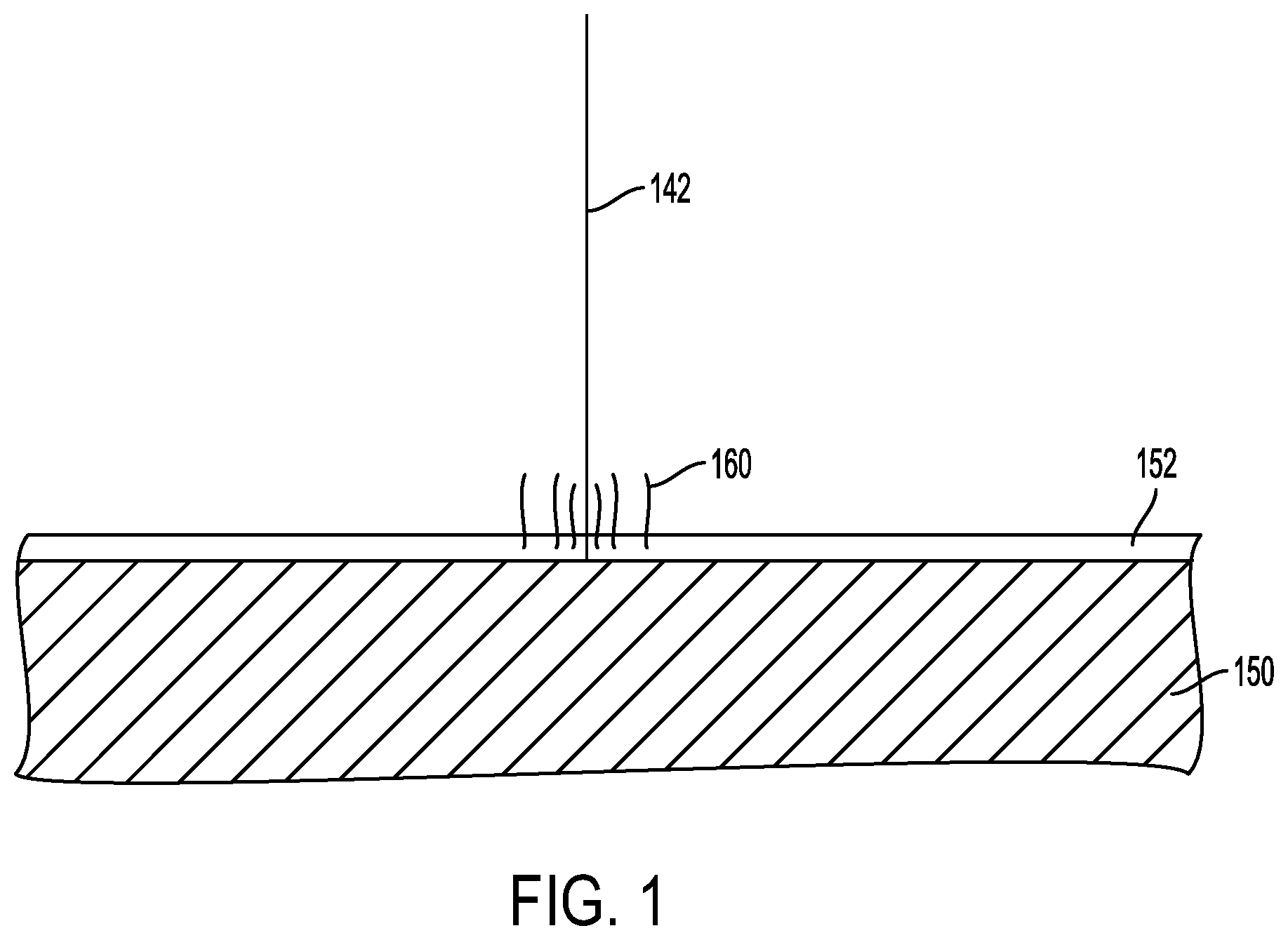
FIG. 1 depicts, in schematic view, an example of the surface of the powdery material which is outgassing when irradiated by the electron beam, outgassing may start due to high temperature only,
FIG. 2 shows, in a schematic view, an example embodiment of a device for producing a three dimensional product in which device a first example embodiment of the inventive method can be applied,
FIG. 3 depicts a finished 3-dimensional article which is reacting with a supplementary gas inside a vacuum chamber,
FIG. 4 depicts, in schematic view, an example of the surface of the powdery material with a charged particle cloud,
FIG. 5 is a block diagram of an exemplary system 1020 according to various embodiments,
FIG. 6A is a schematic block diagram of a server 1200 according to various embodiments, and
FIG. 6B is a schematic block diagram of an exemplary mobile device 1300 according to various embodiments.
DETAILED DESCRIPTION OF VARIOUS EMBODIMENTS
Various embodiments of the present invention will now be described more fully hereinafter with reference to the accompanying drawings, in which some, but not all embodiments of the invention are shown. Indeed, embodiments of the invention may be embodied in many different forms and should not be construed as limited to the embodiments set forth herein. Rather, these embodiments are provided so that this disclosure will satisfy applicable legal requirements. Unless otherwise defined, all technical and scientific terms used herein have the same meaning as commonly known and understood by one of ordinary skill in the art to which the invention relates. The term "or" is used herein in both the alternative and conjunctive sense, unless otherwise indicated. Like numbers refer to like elements throughout.
To facilitate the understanding of this invention, a number of terms are defined below. Terms defined herein have meanings as commonly understood by a person of ordinary skill in the areas relevant to the present invention. Terms such as "a", "an" and "the" are not intended to refer to only a singular entity, but include the general class of which a specific example may be used for illustration. The terminology herein is used to describe specific embodiments of the invention, but their usage does not delimit the invention, except as outlined in the claims.
The term "three-dimensional structures" and the like as used herein refer generally to intended or actually fabricated three-dimensional configurations (e.g. of structural material or materials) that are intended to be used for a particular purpose. Such structures, etc. may, for example, be designed with the aid of a three-dimensional CAD system.
The term "electron beam" as used herein in various embodiments refers to any charged particle beam. The sources of charged particle beam can include an electron gun, a linear accelerator and so on.
FIG. 2 depicts an embodiment of a freeform fabrication or additive manufacturing apparatus 21 in which the inventive methods according to the present invention may be implemented.
The apparatus 21 comprising an electron beam gun 6; deflection coils 7; two powder hoppers 4, 14; a build platform 2; a build tank 10; a powder distributor 28; a powder bed 5; and a vacuum chamber 20.
The vacuum chamber 20 is capable of maintaining a vacuum environment by means of a vacuum system, which system may comprise a turbomolecular pump, a scroll pump, an ion pump and one or more valves which are well known to a skilled person in the art and therefore need no further explanation in this context. The vacuum system is controlled by a control unit 8.
The electron beam gun 6 is generating an electron beam which is used for melting or fusing together powder material provided on the build platform 2. The control unit 8 may be used for controlling and managing the electron beam emitted from the electron beam gun 6. At least one focusing coil (not shown), at least one deflection coil 7, an optional coil for astigmatic correction (not shown) and an electron beam power supply (not shown) may be electrically connected to the control unit 8. In an example embodiment of the invention the electron beam gun 6 generates a focusable electron beam with an accelerating voltage of about 15-60 kV and with a beam power in the range of 3-10 Kw. The pressure in the vacuum chamber may be 1.times.10-3 mbar or lower when building the three-dimensional article by fusing the powder layer by layer with the energy beam.
The powder hoppers 4, 14 comprise the powder material to be provided on the build platform 2 in the build tank 10. The powder material may for instance be pure metals or metal alloys such as titanium, titanium alloys, aluminum, aluminum alloys, stainless steel, Co--Cr alloys, nickel based superalloys etc.
The powder distributor 28 is arranged to lay down a thin layer of the powder material on the build platform 2. During a work cycle the build platform 2 will be lowered successively in relation to a fixed point in the vacuum chamber. In order to make this movement possible, the build platform 2 is in one embodiment of the invention arranged movably in vertical direction, i.e., in the direction indicated by arrow P. This means that the build platform 2 starts in an initial position, in which a first powder material layer of necessary thickness has been laid down. Means for lowering the build platform 2 may for instance be through a servo engine equipped with a gear, adjusting screws etc.
An electron beam may be directed over the build platform 2 causing the first powder layer to fuse in selected locations to form a first cross section of the three-dimensional article. The beam is directed over the build platform 2 from instructions given by the control unit 8. In the control unit 8 instructions for how to control the electron beam for each layer of the three-dimensional article is stored.
After a first layer is finished, i.e., the fusion of powder material for making a first layer of the three-dimensional article, a second powder layer is provided on the build platform 2. The second powder layer is preferably distributed according to the same manner as the previous layer. However, there might be alternative methods in the same additive manufacturing machine for distributing powder onto the work table. For instance, a first layer may be provided by means of a first powder distributor 28, a second layer may be provided by another powder distributor. The design of the powder distributor is automatically changed according to instructions from the control unit 8. A powder distributor 28 in the form of a single rake system, i.e., where one rake is catching powder fallen down from both a left powder hopper 4 and a right powder hopper 14, the rake as such can change design.
After having distributed the second powder layer on the build platform, the energy beam is directed over the work table causing the second powder layer to fuse in selected locations to form a second cross section of the three-dimensional article. Fused portions in the second layer may be bonded to fused portions of the first layer. The fused portions in the first and second layer may be melted together by melting not only the powder in the uppermost powder layer but also remelting at least a fraction of a thickness of a layer directly below the uppermost powder layer.
When an electron beam is used, it is necessary to consider the charge distribution that is created in the powder as the electrons hit the powder bed 5. The charge distribution density depends on the following parameters: beam current, electron velocity (which is given by the accelerating voltage), beam scanning velocity, powder material and electrical conductivity of the powder, i.e. mainly the electrical conductivity between the powder grains. The latter is in turn a function of several parameters, such as temperature, degree of sintering and powder grain size/size distribution.
Thus, for a given powder, i.e. a powder of a certain material with a certain grain size distribution, and a given accelerating voltage, it is possible, by varying the beam current (and thus the beam power) and the beam scanning velocity, to affect the charge distribution.
By varying these parameters in a controlled way, the electrical conductivity of the powder can gradually be increased by increasing the temperature of the powder. A powder that has a high temperature obtains a considerably higher conductivity which results in a lower density of the charge distribution since the charges quickly can diffuse over a large region. This effect is enhanced if the powder is allowed to be slightly sintered during the pre-heating process. When the conductivity has become sufficiently high, the powder can be fused together, i.e. melted or fully sintered, with predetermined values of the beam current and beam scanning velocity.
A general function for describing the charge density that develops in the powder in an arbitrary scanning procedure will be a rather complex function of time and beam position since the charge density generated along one scanned path will be affected by the charge density generated along another scanned path if these paths are not very well separated in space and time. Thus, charge summation effects between different paths must be taken into account.
FIG. 4 shows the upper layer 5' of the powder bed 5 of the powdery material with a charged particle cloud 41. The cloud is concentrated around the position where the electron beam 42 radiates the powdery material. With a higher electrical field, a larger cloud will occur around the radiating point.
Ions created in the vacuum chamber should thus be above a predefined level in order to neutralize enough charges in the surface of the powder. The predefined level should be selected such that it keeps the electrical field strength below E.sub.max. In doing so, enough of the powdery material is neutralized and lifting of powder is prohibited.
FIG. 1 depicts, in schematic view, an example of the surface of the powder layer (152), on top of a partly finished three-dimensional article (150), which is outgassing (160) when irradiated by the electron beam (142). Outgassing may also take place if the temperature is high enough for some other reason, for instance previous already melted powder layer or external heating other than the melting source for the powder material.
The gas is incorporated into the metal powder before it is used. The gas may be chemically bound to the metal powder particles at room temperature. When the powder is heated in the vacuum chamber, the gas is released into the vacuum. The gas will help to prevent smoke since the electron beam may transform the outgassing gas into ions.
Titanium can react with hydrogen gas to form titanium dihydride, TiH2. Titanium dihydride is stable at room temperature, but when it is heated above 300.degree. C., hydrogen gas will start to be released from the titanium.
Ti-6Al-4V powder can be loaded with a predefined hydrogen concentration by heating the powder to a certain temperature in a hydrogen atmosphere. This hydrogen may then be released in the vacuum chamber when the powder is heated by the electron beam, by the partly finished 3-dimensional article and/or by any other heating source such as infrared heating, inductive heating or resistive heating.
The predefined hydrogen concentration in for instance pure Titanium powder or titanium alloy powder may be in the range of 0.01%-0.5% by weight. In another example embodiment the hydrogen concentration in pure titanium powder or titanium alloy powder may be in the range of 0.015-0.35% by weight.
The quantity of gas absorbed by or chemically bonded to the metal powder particles may in itself cause a pressure in the vacuum chamber between 1.times.10-4-1.times.10-1 mbar, which means if additional components are present in the vacuum chamber not emanating from the powder material the additional components may add up to the total pressure in the vacuum chamber. Hydrogen can also be loaded during the powder manufacturing process.
Virgin metal powder (unused metal powder) can be loaded with a specific gas in a separate process before being installed in the additive manufacturing machine. Used powder may be reloaded with the gaseous compound and/or blended with virgin metal powder which is loaded with the gaseous compound. Virgin and/or used powder may be loaded with the gas within the build chamber as a process step before the additive manufacturing process is starting. The vacuum chamber may be filled with the required gas and the powder may be heated to a sufficient temperature in its powder container for allowing the powder to react with or bond to the powder metal particles. During the loading step of the gas into the metal powder in the vacuum chamber, the vacuum pumps may be shut off and the vacuum chamber may be closed to its surrounding media. Vacuum is created as soon as the metal powder is loaded with a sufficient amount of gas. A certain amount of gas is supposed to be loaded in the powder after a certain time period if using a known concentration and a known temperature of the metal powder.
Metal powder loaded with hydrogen is much more inexpensive than inserting helium into the build chamber from an external gas source such as a gas tank. Gas is provided where it is supposed to give effect, i.e., close to the top surface of the metal powder layer. After release of the gas from the metal powder the gas is capable of being transformed into ions by the electron beam. The ions will help to neutralize charged metal particles and thereby prohibit metal powder particles to lift from the powder layer. With the gas loaded into the metal powder there is no need for hardware to control the supply of external gas into the vacuum chamber. Hydrogen is more easily ionized than helium which will increase the likelihood of having ionized hydrogen atoms close to the powder layer surface where it may neutralize the charged metal powder particles. Hydrogen gas is more transparent to the electron beam than helium gas because of its lower atom number. This in turn will reduce its effect on the electron beam, i.e., hydrogen will cause a less divergent electron beam than any other available gas. Since the gas is released only when the temperature of the powder is above a predetermined value, the gas is released when needed. In case of gas supply from an external source the gas need to be supplied continuously and probably in a larger amount for achieving the same effect. Having the powder loaded with the gas one will always be sure that gas will be released for each layer built, whereas in case of external gas supply it may be occasions when an additive manufacturing process may run out of gas which in turn may result in a crash. There is no need for having pressure gauges or gas detectors since one can preload the metal powder with the correct amount of gas from the beginning.
FIG. 3 depicts a second example embodiment according to the present invention. In FIG. 3 it is schematically shown, in a side view, a finished three-dimensional article 320 embedded in non-fused powder material 310 on top of a build table 302 in a build chamber 340. Correct microstructures in the final 3-dimensional article is of outmost importance in various applications. We have found that instead of cooling the final three-dimensional article 320 in helium gas which is currently made, one can cool the final three-dimensional article 320 in pure Hydrogen gas 330 or a gas 330 comprising a certain amount of hydrogen. It is then possible to refine the microstructures in the three-dimensional article 320 wholly or partly within the build chamber. Thermo Hydrogen Processing (THP) is a method for refining microstructures in an article. In THP the article is heated in a hydrogen atmosphere for a certain time and under a certain temperature for loading the article with hydrogen. The hydrogen is then released by heat treatment under vacuum conditions. The inventive idea is to substitute the helium gas in the additive manufacturing process for cooling the final 3-dimensional article with hydrogen gas or a gas comprising a certain amount of hydrogen, for instance a mixture of helium and hydrogen. The loading of hydrogen into the final 3-dimensional article then naturally takes place during its cooling step. The release of hydrogen can be made within the build chamber 340 by heating the 3-dimensional article 320 to a predefined temperature under vacuum conditions. Alternatively the release of hydrogen may take place in a separate process chamber, for instance during a HIP (Hot Isostatic pressure) post treatment step. By incorporating the THP step(s) in the additive manufacturing process one may save manufacturing time as well as redundant process equipment. Hydrogen may be supplied into the build chamber from an external source. Alternatively unused powder in the powder container inside the build chamber may be heated for releasing of hydrogen. Powder material may be preloaded with hydrogen so a heating of the powder container may start release of hydrogen which in turn may be loaded into the final three dimensional article if the final three dimensional article has correct temperature. During the loading of the gas into the final three-dimensional article the vacuum pumps may be switched off. During the release of the hydrogen from the final three-dimensional article, the vacuum pumps may be switched on.
In an example embodiment of the present invention the THP process is taking place within the additive manufacturing equipment and integrated with the cooling of the finished three dimensional article.
External gas supply may be provided via a gas bottle 25 which is connectable to the additive manufacturing apparatus 21 via a pipe 27 and a valve 23, see FIG. 2. The valve is in this embodiment controlled by the control unit 8. When the valve is open gas from the gas source 25 will be provided into the additive manufacturing device 21 through an inlet 22. The valve may be set to any position between fully open and fully closed, i.e., the gas flow may be regulated by the valve 23. In an alternative embodiment a pressure and flow regulator may be provided directly on the gas source 25, leaving the only functionality of the valve 23 to be the opening and closing means for the gas into the additive manufacturing apparatus 21. The gas in the gas source may be used for loading the powder material with a predefined amount of gas and/or the finished three-dimensional article with a predefined amount of gas.
During a preheating the powder provided on the build platform 2 the powder is about to be brought to an appropriate temperature before fusing the powder. This preheating step may be performed by scanning the electron beam over the powder bed in an appropriate manner for heating the powder bed without creating powder smoke. This may be performed by leaving enough spacing between two consecutive scanning lines so the summation of charges in a first scanning line is not affecting the charges provided in the second scanning line. During preheating gas, which is preloaded into the powder material, may be released inside the additive manufacturing apparatus 21 resulting in a pressure level which is high enough for suppressing or eliminating smoke of powder. The pressure level may be around 1.times.10-3 mbar. The pressure level may be at a constant high level throughout the preheating. Alternatively the pressure level is varying during the preheating but always high enough in order to suppress smoke of powder. Smoke of powder is most likely to be present in the beginning of the preheating when no powder is sintered at all. The more the powder is sintered the less is the likelihood of creating smoke of powder. Since most gas is present in the powder material before starting to heat the powder, the gas concentration may be higher in the beginning of the preheating process than at the end of the same. The higher gas concentration in the beginning of the preheating process will reduce or eliminate the risk of powder smoke formation.
During a fusion step 33 the pressure in the additive manufacturing apparatus 21 may be kept as low as possible which may be about 1.times.10-5 mbar or lower. This lower gas pressure is more or less self-regulating since most of or all of the preloaded gas into the powder material has been released during the preheating step. When the actual fusing of the powder material takes place the powder material has no longer any gas bonded to it or chemically reacted with it.
When the fusion step is finalized the powder and fused powder may need some heating in order to be within a predetermined temperature interval. The preheating temperature is material dependent which means that different materials require different preheating temperature intervals. The temperature chosen for the preheating may affect the internal stresses and fatigue properties of the final three dimensional article. When the heating is finalized or when no heating is needed, the process starts all over again by providing the next powder layer.
The pressure level during preheating may be kept at a relatively high pressure in order to ensure a safe suppression of smoke of powder which is very material dependent given the same power of the electron beam. The pressure level during fusion may be kept at a relatively low pressure in order to keep the electron beam quality as good as possible, i.e., as little as possible blurred by interaction of the atoms during the path from an electron beam filament to the powder layer.
A first supplementary gas provided into the vacuum chamber may be capable of reacting chemically with or being absorbed by the finished three-dimensional article. The first supplementary gas may be at least one or more in the group of: Hydrogen, deuterium, hydrocarbons, gaseous organic compounds, ammonia, nitrogen, oxygen, carbon monoxide, carbon dioxide, nitrogen, nitrous oxide, helium, Argon, Neon, Krypton, Xenon and/or Radon.
The pressure level during the chemically reaction with or absorbing by the finished three-dimensional article may be changed depending on the type of first supplementary gas chosen, a lighter atom may need a somewhat higher pressure than a heavier atom chosen among the supplementary gases given above.
A mean pressure level during the preheating may be higher than a mean pressure level during the fusion of the selected locations. The reason of having a higher pressure level of the at least first supplementary gas is to reduce or eliminate the likelihood of powder smoke. A certain number of ions are needed in the vacuum chamber in order to neutralize or decreasing the amount of the charges in the powder created by the ion beam when hitting the powder.
During the fusion one wants to keep the pressure level of the gases in the vacuum chamber at a minimum since the gas atoms may more or less influence the resolution of the electron beam. Depending on the type of ions present in the vacuum chamber there may be some differences in the pressure allowed for maintaining the same electron beam resolution for reasons as explained above.
In another aspect of the invention it is provided a program element configured and arranged when executed on a computer to implement a method as detailed elsewhere herein. The program element may be installed in a computer readable storage medium. The computer readable storage medium may be the control unit 8 or on another control unit. The computer readable storage medium and the program element, which may comprise computer-readable program code portions embodied therein, may further be contained within a non-transitory computer program product. Further details regarding these features and configurations are provided, in turn, below.
As mentioned, various embodiments of the present invention may be implemented in various ways, including as non-transitory computer program products. A computer program product may include a non-transitory computer-readable storage medium storing applications, programs, program modules, scripts, source code, program code, object code, byte code, compiled code, interpreted code, machine code, executable instructions, and/or the like (also referred to herein as executable instructions, instructions for execution, program code, and/or similar terms used herein interchangeably). Such non-transitory computer-readable storage media include all computer-readable media (including volatile and non-volatile media).
In one embodiment, a non-volatile computer-readable storage medium may include a floppy disk, flexible disk, hard disk, solid-state storage (SSS) (e.g., a solid state drive (SSD), solid state card (SSC), solid state module (SSM)), enterprise flash drive, magnetic tape, or any other non-transitory magnetic medium, and/or the like. A non-volatile computer-readable storage medium may also include a punch card, paper tape, optical mark sheet (or any other physical medium with patterns of holes or other optically recognizable indicia), compact disc read only memory (CD-ROM), compact disc compact disc-rewritable (CD-RW), digital versatile disc (DVD), Blu-ray disc (BD), any other non-transitory optical medium, and/or the like. Such a non-volatile computer-readable storage medium may also include read-only memory (ROM), programmable read-only memory (PROM), erasable programmable read-only memory (EPROM), electrically erasable programmable read-only memory (EEPROM), flash memory (e.g., Serial, NAND, NOR, and/or the like), multimedia memory cards (MMC), secure digital (SD) memory cards, SmartMedia cards, CompactFlash (CF) cards, Memory Sticks, and/or the like. Further, a non-volatile computer-readable storage medium may also include conductive-bridging random access memory (CBRAM), phase-change random access memory (PRAM), ferroelectric random-access memory (FeRAM), non-volatile random-access memory (NVRAM), magnetoresistive random-access memory (MRAM), resistive random-access memory (RRAM), Silicon-Oxide-Nitride-Oxide-Silicon memory (SONOS), floating junction gate random access memory (FJG RAM), Millipede memory, racetrack memory, and/or the like.
In one embodiment, a volatile computer-readable storage medium may include random access memory (RAM), dynamic random access memory (DRAM), static random access memory (SRAM), fast page mode dynamic random access memory (FPM DRAM), extended data-out dynamic random access memory (EDO DRAM), synchronous dynamic random access memory (SDRAM), double data rate synchronous dynamic random access memory (DDR SDRAM), double data rate type two synchronous dynamic random access memory (DDR2 SDRAM), double data rate type three synchronous dynamic random access memory (DDR3 SDRAM), Rambus dynamic random access memory (RDRAM), Twin Transistor RAM (TTRAM), Thyristor RAM (T-RAM), Zero-capacitor (Z-RAM), Rambus in-line memory module (RIMM), dual in-line memory module (DIMM), single in-line memory module (SIMM), video random access memory VRAM, cache memory (including various levels), flash memory, register memory, and/or the like. It will be appreciated that where embodiments are described to use a computer-readable storage medium, other types of computer-readable storage media may be substituted for or used in addition to the computer-readable storage media described above.
As should be appreciated, various embodiments of the present invention may also be implemented as methods, apparatus, systems, computing devices, computing entities, and/or the like, as have been described elsewhere herein. As such, embodiments of the present invention may take the form of an apparatus, system, computing device, computing entity, and/or the like executing instructions stored on a computer-readable storage medium to perform certain steps or operations. However, embodiments of the present invention may also take the form of an entirely hardware embodiment performing certain steps or operations.
Various embodiments are described below with reference to block diagrams and flowchart illustrations of apparatuses, methods, systems, and computer program products. It should be understood that each block of any of the block diagrams and flowchart illustrations, respectively, may be implemented in part by computer program instructions, e.g., as logical steps or operations executing on a processor in a computing system. These computer program instructions may be loaded onto a computer, such as a special purpose computer or other programmable data processing apparatus to produce a specifically-configured machine, such that the instructions which execute on the computer or other programmable data processing apparatus implement the functions specified in the flowchart block or blocks.
These computer program instructions may also be stored in a computer-readable memory that can direct a computer or other programmable data processing apparatus to function in a particular manner, such that the instructions stored in the computer-readable memory produce an article of manufacture including computer-readable instructions for implementing the functionality specified in the flowchart block or blocks. The computer program instructions may also be loaded onto a computer or other programmable data processing apparatus to cause a series of operational steps to be performed on the computer or other programmable apparatus to produce a computer-implemented process such that the instructions that execute on the computer or other programmable apparatus provide operations for implementing the functions specified in the flowchart block or blocks.
Accordingly, blocks of the block diagrams and flowchart illustrations support various combinations for performing the specified functions, combinations of operations for performing the specified functions and program instructions for performing the specified functions. It should also be understood that each block of the block diagrams and flowchart illustrations, and combinations of blocks in the block diagrams and flowchart illustrations, could be implemented by special purpose hardware-based computer systems that perform the specified functions or operations, or combinations of special purpose hardware and computer instructions.
FIG. 5 is a block diagram of an exemplary system 1020 that can be used in conjunction with various embodiments of the present invention. In at least the illustrated embodiment, the system 1020 may include one or more central computing devices 1110, one or more distributed computing devices 1120, and one or more distributed handheld or mobile devices 1300, all configured in communication with a central server 1200 (or control unit) via one or more networks 1130. While FIG. 5 illustrates the various system entities as separate, standalone entities, the various embodiments are not limited to this particular architecture.
According to various embodiments of the present invention, the one or more networks 1130 may be capable of supporting communication in accordance with any one or more of a number of second-generation (2G), 2.5G, third-generation (3G), and/or fourth-generation (4G) mobile communication protocols, or the like. More particularly, the one or more networks 1130 may be capable of s
D00000
D00001
D00002
D00003
D00004
D00005
D00006
D00007
XML
uspto.report is an independent third-party trademark research tool that is not affiliated, endorsed, or sponsored by the United States Patent and Trademark Office (USPTO) or any other governmental organization. The information provided by uspto.report is based on publicly available data at the time of writing and is intended for informational purposes only.
While we strive to provide accurate and up-to-date information, we do not guarantee the accuracy, completeness, reliability, or suitability of the information displayed on this site. The use of this site is at your own risk. Any reliance you place on such information is therefore strictly at your own risk.
All official trademark data, including owner information, should be verified by visiting the official USPTO website at www.uspto.gov. This site is not intended to replace professional legal advice and should not be used as a substitute for consulting with a legal professional who is knowledgeable about trademark law.