Enclosures for treating materials
Medoff , et al. Fe
U.S. patent number 10,549,241 [Application Number 14/299,002] was granted by the patent office on 2020-02-04 for enclosures for treating materials. This patent grant is currently assigned to Xyleco, Inc.. The grantee listed for this patent is Xyleco, Inc.. Invention is credited to Thomas Craig Masterman, Marshall Medoff, Robert Paradis.


| United States Patent | 10,549,241 |
| Medoff , et al. | February 4, 2020 |
Enclosures for treating materials
Abstract
Biomass (e.g., plant biomass, animal biomass, and municipal waste biomass) is processed to produce useful intermediates and products, such as energy, fuels, foods or materials. For example, systems and methods are described that can be used to treat feedstock materials, such as cellulosic and/or lignocellulosic materials, in two or more vaults that can share a common wall.
| Inventors: | Medoff; Marshall (Brookline, MA), Masterman; Thomas Craig (Rockport, MA), Paradis; Robert (Burlington, MA) | ||||||||||
|---|---|---|---|---|---|---|---|---|---|---|---|
| Applicant: |
|
||||||||||
| Assignee: | Xyleco, Inc. (Wakefield,
MA) |
||||||||||
| Family ID: | 51491991 | ||||||||||
| Appl. No.: | 14/299,002 | ||||||||||
| Filed: | June 9, 2014 |
Prior Publication Data
| Document Identifier | Publication Date | |
|---|---|---|
| US 20140284205 A1 | Sep 25, 2014 | |
Related U.S. Patent Documents
| Application Number | Filing Date | Patent Number | Issue Date | ||
|---|---|---|---|---|---|
| PCT/US2014/021604 | Mar 7, 2014 | ||||
| 61774684 | Mar 8, 2013 | ||||
| 61774773 | Mar 8, 2013 | ||||
| 61774731 | Mar 8, 2013 | ||||
| 61774735 | Mar 8, 2013 | ||||
| 61774740 | Mar 8, 2013 | ||||
| 61774744 | Mar 8, 2013 | ||||
| 61774746 | Mar 8, 2013 | ||||
| 61774750 | Mar 8, 2013 | ||||
| 61774752 | Mar 8, 2013 | ||||
| 61774754 | Mar 8, 2013 | ||||
| 61774775 | Mar 8, 2013 | ||||
| 61774780 | Mar 8, 2013 | ||||
| 61774761 | Mar 8, 2013 | ||||
| 61774723 | Mar 8, 2013 | ||||
| 61793336 | Mar 15, 2013 | ||||
| Current U.S. Class: | 1/1 |
| Current CPC Class: | C12M 47/00 (20130101); C12P 19/02 (20130101); D21C 9/007 (20130101); G21F 7/00 (20130101); G21K 5/10 (20130101); C12P 19/14 (20130101); B65G 27/00 (20130101); C10L 9/08 (20130101); C12P 7/52 (20130101); C07C 31/12 (20130101); C13K 13/002 (20130101); C07C 29/149 (20130101); B65G 53/40 (20130101); B01D 61/44 (20130101); C12P 7/56 (20130101); C10G 1/00 (20130101); E04B 1/92 (20130101); B01D 15/02 (20130101); C12P 7/04 (20130101); B01D 61/445 (20130101); C10L 1/026 (20130101); C12M 47/10 (20130101); B01J 19/085 (20130101); H01J 37/317 (20130101); B65G 53/04 (20130101); B01D 53/32 (20130101); C12P 7/06 (20130101); C10L 1/023 (20130101); C13K 1/02 (20130101); C12P 7/10 (20130101); C07C 29/149 (20130101); C07C 31/12 (20130101); C12P 2203/00 (20130101); C12P 2201/00 (20130101); Y02W 10/40 (20150501); H01J 2237/3165 (20130101); B01J 2219/0869 (20130101); Y02W 10/33 (20150501); E04B 2001/925 (20130101); Y02P 20/133 (20151101); B01J 2219/0886 (20130101); B01J 2219/0879 (20130101); C10L 2200/0469 (20130101); Y02E 50/10 (20130101); C10L 2290/36 (20130101); H01J 2237/31 (20130101); C10L 2200/0476 (20130101); H01J 2237/202 (20130101); Y02E 50/30 (20130101); Y02E 60/16 (20130101); Y02W 10/37 (20150501) |
| Current International Class: | B01D 61/44 (20060101); B01D 15/02 (20060101); B01J 19/08 (20060101); C10L 1/02 (20060101); C10G 1/00 (20060101); D21C 9/00 (20060101); B65G 53/04 (20060101); C07C 31/12 (20060101); B65G 27/00 (20060101); C12P 7/56 (20060101); C07C 29/149 (20060101); C12P 7/04 (20060101); C12P 19/14 (20060101); C12P 19/02 (20060101); B65G 53/40 (20060101); C13K 13/00 (20060101); C10L 9/08 (20060101); C13K 1/02 (20060101); C12P 7/52 (20060101); H01J 37/317 (20060101); C12P 7/10 (20060101); G21F 7/00 (20060101); C12M 1/00 (20060101); B01D 53/32 (20060101); C12P 7/06 (20060101); E04B 1/92 (20060101) |
| Field of Search: | ;204/157.6-158.14 ;422/186 |
References Cited [Referenced By]
U.S. Patent Documents
| 2674381 | April 1954 | Cady |
| 2985589 | May 1961 | Broughton et al. |
| 3434850 | March 1969 | Huff |
| 4201918 | May 1980 | Latzer |
| 4316747 | February 1982 | Rugg et al. |
| 4387476 | June 1983 | Bueb et al. |
| 4769082 | September 1988 | Kumakura |
| 4813532 | March 1989 | Harper |
| 5131525 | July 1992 | Musschoot |
| 5142023 | August 1992 | Gruber et al. |
| 5247058 | September 1993 | Gruber et al. |
| 5247059 | September 1993 | Gruber et al. |
| 5258488 | November 1993 | Gruber et al. |
| 5274073 | December 1993 | Gruber et al. |
| 5338822 | August 1994 | Gruber et al. |
| 5357035 | October 1994 | Gruber et al. |
| 5392529 | February 1995 | Bailey et al. |
| 5457269 | October 1995 | Schonberg |
| 5462155 | October 1995 | Demar et al. |
| 5475080 | December 1995 | Gruber et al. |
| 5484881 | January 1996 | Gruber et al. |
| 5525706 | June 1996 | Gruber et al. |
| 5536807 | July 1996 | Gruber et al. |
| 5539081 | July 1996 | Gruber et al. |
| 5574129 | November 1996 | Miyoshi et al. |
| 5585191 | December 1996 | Gruber et al. |
| 5665474 | September 1997 | Gruber et al. |
| 5763564 | June 1998 | Gruber et al. |
| 5773562 | June 1998 | Gruber et al. |
| 5798436 | August 1998 | Gruber et al. |
| 5807973 | September 1998 | Gruber et al. |
| 5849401 | December 1998 | El-Afandi et al. |
| 5852166 | December 1998 | Gruber et al. |
| 5882737 | March 1999 | Eckhoff |
| 5916929 | June 1999 | Knobel et al. |
| 5981694 | November 1999 | Gruber et al. |
| 5994706 | November 1999 | Allen et al. |
| 6005067 | December 1999 | Gruber et al. |
| 6005068 | December 1999 | Gruber et al. |
| 6093791 | July 2000 | Gruber et al. |
| 6111060 | August 2000 | Gruber et al. |
| 6114495 | September 2000 | Kolstad et al. |
| 6121410 | September 2000 | Gruber et al. |
| 6140458 | October 2000 | Terado et al. |
| 6143863 | November 2000 | Gruber et al. |
| 6160173 | December 2000 | Eyal et al. |
| 6183814 | February 2001 | Nangeroni et al. |
| 6207792 | March 2001 | Gruber et al. |
| 6217630 | April 2001 | Chanen et al. |
| 6229046 | May 2001 | Eyal et al. |
| 6277951 | August 2001 | Gruber et al. |
| 6320077 | November 2001 | Eyal et al. |
| 6323307 | November 2001 | Bigg et al. |
| 6326458 | December 2001 | Gruber et al. |
| 6353086 | March 2002 | Kolstad et al. |
| 6355772 | March 2002 | Gruber et al. |
| 6429280 | August 2002 | Hiroaka et al. |
| 6452051 | September 2002 | Eyal |
| 6506873 | January 2003 | Ryan et al. |
| 6528617 | March 2003 | Terado et al. |
| 6528800 | March 2003 | Dzeierzynski et al. |
| 6534679 | March 2003 | Eyal et al. |
| 6608882 | August 2003 | Allen et al. |
| 6628750 | September 2003 | Korenev |
| 6713773 | March 2004 | Lyons et al. |
| 6740731 | May 2004 | Bigg et al. |
| 6780448 | August 2004 | Howard |
| 6833551 | December 2004 | Avnery |
| 6838678 | January 2005 | Bujak et al. |
| 6846657 | January 2005 | Heikkilaet et al. |
| 7019170 | March 2006 | Eyal et al. |
| 7026145 | April 2006 | Mizrahi et al. |
| 7083955 | August 2006 | Otto |
| 7098009 | August 2006 | Shanmugam et al. |
| 7144977 | December 2006 | Eyal et al. |
| 7153533 | December 2006 | Burke et al. |
| 7186541 | March 2007 | Gokarn et al. |
| 7217545 | May 2007 | Agblevor et al. |
| 7273734 | September 2007 | Minami et al. |
| 7309597 | December 2007 | Liao et al. |
| 7393676 | July 2008 | Gokarn et al. |
| 7638316 | December 2009 | Gokarn et al. |
| 7932065 | April 2011 | Medoff |
| 8030045 | October 2011 | Jessen et al. |
| 8076120 | December 2011 | Gokarn et al. |
| 8088427 | January 2012 | Engleson et al. |
| 8142620 | March 2012 | Medoff |
| 8173753 | May 2012 | Nagano et al. |
| 8198066 | June 2012 | Gokarn et al. |
| 8728770 | May 2014 | Ishikawa |
| 9187769 | November 2015 | Medoff |
| 9334518 | May 2016 | Medoff |
| 9464334 | October 2016 | Medoff |
| 2002/0132313 | September 2002 | Lin et al. |
| 2002/0135290 | September 2002 | Avnery |
| 2002/0016629 | November 2002 | Zeik |
| 2003/0009931 | January 2003 | Hunt |
| 2003/0098373 | May 2003 | Smith |
| 2003/0129274 | July 2003 | Garwood |
| 2008/0313954 | December 2008 | Lee et al. |
| 2009/0007484 | January 2009 | Smith |
| 2009/0246843 | October 2009 | Edlauer et al. |
| 2009/0286295 | November 2009 | Medoff et al. |
| 2010/0087687 | April 2010 | Medoff |
| 2010/0112242 | May 2010 | Medoff |
| 2010/0200806 | August 2010 | Medoff |
| 2010/0230270 | September 2010 | Lee |
| 2010/0287826 | November 2010 | Hoffman et al. |
| 2010/0304439 | December 2010 | Medoff |
| 2011/0236946 | September 2011 | Maclachlan et al. |
| 2015/0216106 | August 2015 | Kotte |
| 101202127 | Jun 2008 | CN | |||
| 102066063 | May 2011 | CN | |||
| 102216435 | Oct 2011 | CN | |||
| 202670653 | Jan 2013 | CN | |||
| 2538080 | Mar 1977 | DE | |||
| 2098556 | Sep 2009 | EP | |||
| 2172568 | Apr 2010 | EP | |||
| 2298363 | Aug 1976 | FR | |||
| S648969 | Jan 1989 | JP | |||
| H11337700 | Dec 1999 | JP | |||
| 2000304900 | Nov 2000 | JP | |||
| 2001242297 | Sep 2001 | JP | |||
| 2001318200 | Nov 2001 | JP | |||
| 2002085029 | Mar 2002 | JP | |||
| 2002096049 | Apr 2002 | JP | |||
| 2002224656 | Aug 2002 | JP | |||
| 2005000848 | Jan 2005 | JP | |||
| 199324704 | Dec 1993 | WO | |||
| 2007009463 | Jan 2007 | WO | |||
| 2009134748 | Nov 2009 | WO | |||
| 2009134791 | Nov 2009 | WO | |||
| 2010056940 | May 2010 | WO | |||
| 2011/149774 | Dec 2011 | WO | |||
Other References
|
"Vibrating conveyors--Glossary--Schenck Process," downloaded from https://www.schenckprocess.com/products/glossary/vibrating-conveyors on Apr. 16, 2019 (Year: 2019). cited by examiner . Haug, G., "Aspects of Rotary Vacuum Filter Design & Performance," Reprint from Fluid/Particle Separation Journal, vol. 13(1): Apr. 2000 (19 pages). cited by applicant . BHS Sonthofen GmbH--BF Indexing Belt Filter "Gentle filtration of Sedimenting Media," www.bhs-sonthofen.com 2012 (16 pages). cited by applicant . Technical Bulletin by Osprey Corporation, Spring 2004 (2 pages). cited by applicant . Filter Cloth, by Kavon Filter Products Co., Feb. 26, 2012 (3 pages). cited by applicant . Rotary Drum Vacuum Filter, by Komline-Sanderson, 1996 (8 pages). cited by applicant . BHS Sonthofen GmbH--RPF Rotary Pressure Filter "Precise Separation of Suspensions," www.bhs-sonthofen.com 2012 (12 pages). cited by applicant . Filter Cloth, by Suita Group, Feb. 26, 2013 (3 pages) www.filtercloths.cn. cited by applicant . "An Introduction to Steam Boilers and Steam Raising," by N.E.M. Business Solutions, Nov. 15, 2012. (23 pages) www.cip.ukcentre.com/steam.htm. cited by applicant . Strempek, J.R. et al., A Technical Paper, "Innovative Solutions for a Challenging Biomass Fuel and Boiler Upgrade Project," TAPPI Engineering Pulping, Environmental Conference Aug. 28-31, 2005 (11 pages). cited by applicant . Cellulose Ethanol (Cellulosic Ethanol), www.zfacts.com (Feb. 27, 2013, 4 pages). cited by applicant . Technical Study Report on "Biomass Fired--Fluidized Bed Combustion Boiler Technology for Cogeneration" by UNEP www.uneptie.frienergy (Sep. 2007, 68 pages). cited by applicant . "Biomass Conversion Technologies," Chapter 5, EPA Combined Heat and Power Partnership : Biomass CHP Catalog, (32 pages) www.epa.gov (Accessed Jun. 12, 2014). cited by applicant . "Biomass Technology Review," Prepared for Biomass Power Association by McHale & Associates, Inc. Oct. 21, 2010 (52 pages). cited by applicant . "Holo-Flite Thermal Processor," Metso Minerals Industries Inc. (2012, 8 pages). cited by applicant . Kamp, P. "Inbicon Biomass Refinery Cellulosic Ethanol Technology Platforms; Growth and Sustainability through Biomass Refining, CHP--Technology Review," Inbicon Leifmark, North America Business Development (2010, 40 pages). cited by applicant . "Thermal Degradation of Wood Components: A Review of the Literature," U.S.D.A. Forest Service Research Paper, FPL 130 (May 1970, 29 pages). cited by applicant . Belderock, H.J.M., Master Thesis entitled "Experimental Investigation and Modeling of the Pyrolysis of Biomass," Eindhoven University of Technology, The Netherlands (Dec. 2007, 125 pages). cited by applicant . Cleland, M.R., "Industrial Applications of Electron Accelerators." Ion Beam Applications, Edgewood, NY 11717, USA http://cds.cern.ch/record/1005393/files/p383.pdf?version=1 (Accessed Jun. 12, 2014, 34 pages). cited by applicant . Krumeich, F., "Properties of Electrons, their Interactions with Matter and Applications in Electron Microscopy," Laboratory of Inorganic Chemistry, ETH Zurich, HCI-H1111, CH-8093 Zurich http://www.microscopy.ethz.ch/downloads/Interactions.pdf (Accessed Jun. 12, 2014 23 pages). cited by applicant . Author unknown, "The Case for Geothermal," www.gladwell.com (Aug. 7, 2006, 10 pages). cited by applicant . "Recommendations for Geothermal Heating and Cooling Systems," State of Ohio, Ohio Water Resources Council, State Coordinating Committee on Ground Water (Feb. 2012, 32 pages). cited by applicant . Swanson, K. "Broadbeam--Getting Started with EB," PCT Engineered Systems LLC. (2012, 9 pages). cited by applicant . "Guidelines for Ozone Mitigation at the APS," Advanced Photon Source, (May 1994, 20 pages). cited by applicant . Gundel, L.A. et al., "A Pilot Study of Energy Efficient Air Cleaning for Ozone," Indoor Environment Department, Environmental Energy Technologies Division, Lawrence Berkeley National Laboratory, Berkeley, CA 94720 (Nov. 28, 2002, 14 pages). cited by applicant . "Product Bulletin: Ozone Destruct Unit," Corporate Consulting Service Instruments, Inc., Manufactured in Akron, Ohio 44301 USA http://www.ccsi-inc.com/pb-ozone-destruct.pdf (Accessed Jun. 12, 2014, 2 pages). cited by applicant . Shepherd, A. "Activated Carbon Adsorption for Treatment of VOC Emissions," Presented at the 13th Annual EnviroExpo, Boston, Massachusetts (May 2001, 4 pages). cited by applicant . Fare, T.L. et al., "Effects of Atmospheric Ozone on Microarray Data Quality," Analytical Chemistry (2003, 4 pages). cited by applicant . Swanson, W.P., "Toxic Gas Production at Electron Linear Accelerators," Stanford Linear Accelerator Center, Stanford University, Stanford, California 94305 (Feb. 1980, 11 pages). cited by applicant . "The advantage of physically separating airflow for each conveyor," Air Flow Two Technology by Extru-Tech, Inc. www.extru-techinc.com (Accessed Jun. 12, 2014, 4 pages). cited by applicant . "DustBeater, DB8 and DB12 Models with MLC6 Control--User Guide," for Tthe Conair Group, Inc, Pittsburgh, PA 15202 www.conairnet.com (2002, 68 pages). cited by applicant . "TLM Model Tube Loaders, Hopper Loading and Direct Feed Configurations with MLC2 Control--User Guide," for The Conair Group, Inc, Pittsburgh, PA 15202 www.conairnet.com (2002, 45 pages). cited by applicant . "TLA Model Tube Loaders, Hopper Loading, Feeding Bin and Direct Feed Configurations--User Guide," for The Conair Group, Inc, Pittsburgh, PA 15202 www.conairnet.com (2003, 38 pages). cited by applicant . "Access Loader with Easy Loading Control (ELC), Models AL2 and AL5--User Guide," for The Conair Group, Inc, Pittsburgh, PA 15202 www.conairnet.com (2008, 109 pages). cited by applicant . "CAML-EVG Compressed Air Material Evacuator--User Guide," for The Conair Group, Inc, Pittsburgh, PA 15202 www.conairnet.com (2001, 48 pages). cited by applicant . Abdel-Rahman, M.A. et al., "Lactic Acid Production from Lignocellulose-Derived Sugars Using Lactic Acid Bacteria: Overview and Limits," J. Biotechnol., vol. 156: 286-301 (2011). cited by applicant . Moniz-Xavier, A.M.M., Master Thesis entitled "Study of Lactic Acid Polycondensation and Lactide Production," Developed for the Dissertation Project realized in Eidgenossische Technische Hochschule Zurich, for Universidade do Porto (Jul. 2010, 71 pages). cited by applicant . Mukhopadhyay, A., A Thesis entitled: "Bioconversion of Paper Mill Lignocellulosic Materials to Lacid Acid Using Cellulase Enzyme Complex and Microbial Cultures," prepared for Department of Grain Science and Industry College of Agriculture, Kansas State University, Manhattan Kansas (2009, 60 pages). cited by applicant . Ahmed, J. and Varsheney, S.K., "Polylactides-Chemistry, Properties and Green Packaging Technology: A Review," Intl. J. Food Properties, vol. 14(1): 37-58 (2011). cited by applicant . Xiao, Y., A Thesis entitled: "Functional Polymers by Enzymatic Catalysis," Supported by Marie Curie Action RTN program Biocatalytic Approach to Material Design, Contract No. MRTN-CT-2004-505147 (2009, 148 pages). cited by applicant . Abdel-Rahman, M. et al., "Efficient Homofermentative L-(+)-Lactic Acid Production from Xylose by a Novel Lactic Acid Bacterium, Enterococcus mundtii QU 25," Appl. Environ. Microbiol., vol. 77(5): 1892-1895 (Mar. 2011). cited by applicant . Miller, D.J. and Doidge, Br., "Biochemicals From Corn: Update 2008," for Ontario BioAuto Council, Ontario Agri-Food Technologies, Ontario Ministry of Agriculture, Food and Rural Affairs (46 pages). cited by applicant . Wang, L. et al., "Efficient production of L-lactic acid from corncob molasses, a waste by-product in xylitol production, by a newly isolated xylose utilizing Bacillus sp. strain," Bioresour. Technol. (2010, 8 pages). cited by applicant . Hassan, E., et al., "Dynamic Mechanical Properties and Thermal Stability of Poly(lactid acid) and Poly(butylene succinate) Blends Composites," J. Fiber Bioengineer. Inform., vol. 6(1): 85-94 (2013). cited by applicant . Osmundsen, C.M., "Catalysis & Biomass: Strategies for Biomass Conversion to Fuels and Chemicals," for Haldor Topsoe/DTU (Mar. 2011, 39 pages). cited by applicant . Chen, C.C. and Ju, L-K, "Coupled Lactic Acid Fermentation and Adsorption," Appl. Microbiol. Biotechnol., vol. 59: 170-174 (2002). cited by applicant . Dutkiewicz, S. et al., "Synthesis of Poly(L(+) Lactic Acid) by Polycondensation Method in Solution," Fibres & Textiles in Eastern Europe, vol. 11(4)(43): 66-70 (Dec. 2003). cited by applicant . Edreder, E.A. et al., "Optimization of Batch Reactive Distillation Process: Production of Lactic Acid," 20th European Symposium on Computer Aided Process Engineering--ESCAPE20, Ed. S. Pierucci and G. Buzzi Ferraris (2010, 6 pages). cited by applicant . Malinowski, R. et al., "Effects of Electron Radiation on Properties of PLA," Archives of Materials Science and Engineering, vol. 49(1): 25-32 (May 2011). cited by applicant . Fakhravar, S. et al., "Fermentative Lactic Acid from Deproteinized Whey Using Lactobacillus bulgaricus in Batch Culture," World Applied Sciences Journal, vol. 17(9): 1083-1086 (2012). cited by applicant . Garlotta, D., "A Literature Review of Poly(Lactic Acid)," J. Polymers and the Environ., vol. 9(2): 63-84 (2001). cited by applicant . Habova, V. et al., "Modern Method of Lactic Acid Recovery from Fermentation Broth," Czech J. Food Sci., vol. 22(3): 87-94 (2004). cited by applicant . Halasz, K. and Csoka, L., "Plasticized Biodegradable Poly(lactic acid) Based Composites Containing Cellulose in Micro-and Nanosize," J. Engineer., vol. 2013, Article ID 329379 (2012, 9 pages). cited by applicant . Henton, D.E. et al., "Polylactic Acid Technology," Ch. 16, in Natural Fibers, Biopolymers, and Biocomposites http://www.jimluntllc.com/pdfs/polylactic_acid_technology.pdf (Accessed Jun. 12, 2014, pp. 527-577). cited by applicant . Walton, S. et al., "Production of lactic acid from hemicellulose extracts by Bacillus coagulans MXL-9," J. Ind. Microbiol. Biotechnol., vol. 37: 823-830 (2010). cited by applicant . INGEO Resin Product Guide, for NatureWorks LLC. www.natureworksllc.com (2011, 4 pages). cited by applicant . Jonglertjunya, W. et al., "Utilization of Sugarcane Bagasses for Lactic Acid Production by Acid Hydrolysis and Fermentation Using Lactobacillus sp.," World Academy of Science, Engineering and Technology, vol. 66: 173-178 (2012). cited by applicant . Liu, L. et al., "Phosphoketolase Pathway for Xylose Catabolism in Clostridium acetocuylicum Revealed by C Metabolic Flux Analysis," J. Bacteriol., vol. 194(19): 5413-5422 (Oct. 2012). cited by applicant . Lunt, J. and Shafer, A.L., "Polylactic Acid Polymers from Corn--Applications in the Textiles Industry," for Cargill Dow Polymers LLC., Minnetonka, MN 55345 http://jimluntllc.com/pdfs/PolylacticAcidPolymersFromCorn.pdf (Accessed Jun. 12, 2014, 8 pages). cited by applicant . Maas, R.H.W. et al., "Lactic Acid Production From Xylose by the Fungus Rhizopus oryzae," Appl. Microbiol. Biotechnol., vol. 72: 861-868 (2006). cited by applicant . Middleton, J.C. and Tipton, A.J., "Synthetic Biodegradable Polymers as Orthopedic Devices," Biomaterials, vol. 21: 2335-2346 (2000). cited by applicant . Narayanan, N. et al., "L(+) lactic acid fermentation and its product polymerization," Electr. J. of Biotechnol., vol. 7(2) (2004, 13 pages). cited by applicant . Neureiter, M. et al., "Lignocellulose Feedstocks for the Production of Lactic Acid," Chem. Biochem. Eng. Q., vol. 18(1): 55-63 (2004). cited by applicant . Oh, H. et al., "Lactic Acid Production Through Cell-Recycle Repeated-Batch Bioreactor," Appl. Biochem. Biotechnol., vol. 105-108: 603-613 (2003). cited by applicant . Sriwongsa, K. et al., "Radiation-Induced Crosslinking of Polylactic Acid: Effects of Air and Vacuum," for TIChE International Conference at Hatyai, Songkhla Thailand (Nov. 10-11, 2011, 5 pages). cited by applicant . Razak, S. et al., "Biodegradable Polymers and their Bone Applications: A Review," Intl. J. Basic & Applied Sciences, vol. 12(1): 31-49 (2012). cited by applicant . Moon, S-L, et al., "Melt Polycondensation of L-Lactic Acid with Sn(II) Catalysts Activated by Various Proton Acids: A Direct Manufacturing Route to High Molecular Weight Poly(L-lactic acid)," J. Polymer Science: Part A: Polymer Chemistry, vol. 38: 1673-1679 (2000). cited by applicant . Technology Focus Report: Blends of PLA with Other Thermoplastics, for NatureWorks LLC. www.natureworksllc.com (2007, 6 pages). cited by applicant . Anuar, H. and Zuraida, A., "Thermal Properties of Injection Moulded Polylactic Acid--Kenaf Fibre Biocomposite," Malaysian Polymer J., vol. 6(1): 51-57 (2011). cited by applicant . Ahmed, J. et al., "Thermal Properties of Polylactides," J. Thermal Analysis and Calorimetry, vol. 95(3): 957-964 (2009). cited by applicant . Werpy, T. et al., "Top Value-Added Chemicals from Biomass, vol. I--Results of Screening for Potential Candidates from Sugars and Synthesis Gas," by Pacific Northwest Laboratory, for U.S. Department of Energy (Aug. 2007, 76 pages). cited by applicant . Holladay, J.E. et al., "Top Value-Added Chemicals from Biomass, vol. II--Results of Screening for Potential Candidates from Biorefinery Lignin," by Pacific Northwest National Laboratory, for U.S. Department of Energy under Contract DE-AC05-76RL01830 (Oct. 2007, 87 pages). cited by applicant . Wang, N. et al., "Synthesis, characterization, biodegradation, and drug delivery application of biodegradable lactic / glycolic acid acid polymers: I. Synthesis and characterization," J. Biomater. Sci. Polymer Edn., vol. 11(3): 301-318 (2000). cited by applicant . Wee, Y-J, et al., "Biotechnological Production of Lactic Acid and Its Recent Applications," Food Technol. Biotechnol., vol. 44(2): 163-12 (2006). cited by applicant . Xiao, L. et al., "Poly(Lactic Acid)-Based Biomaterials: Synthesis, Modification and Applications," Biomedical Science, Engineering and Technology http://www.intechopen.com/books/biomedical-science-engineering-and-techno- logy/poly-lactic-acid-based-biomaterials-synthesis-modification-and-applic- ations (Accessed Jun. 12, 2014 38 pages). cited by applicant . Zhang, W-x and Wang, Y-z, "Synthesis and Properties of High Molecular Weight Poly(Lactic Acid) and Its Resultant Fibers," Chinese J. Polymer Sci., vol. 26(4): 425-432 (2008). cited by applicant . Search Report--Corresponding Singapore Application No. 11201502296Y, dated Aug. 4, 2016, 2 pages. cited by applicant . Karthika K. et al., "Enzymatic Hydrolysis and Characterization of Lignocellulosic Biomass Exposed to Electron Beam Irradiation", Carbohydrate Polymers, vol. 90, No. 2, Jun. 28, 2012, pp. 1038-1045. cited by applicant . How to Choose and Use Vibratory Feeders and Conveyors, Eriez Magnetics, 2007, pp. 1-15. cited by applicant . Machine Translation of JP11337700, Mutsumi et al., pp. 1-4, 1999. cited by applicant . A. Korolev et al., "Characteristics of Sealed-Off Electron Gun with Wide Beam", Proceedings of EPAC, Lucerne, Switzerland, 2004, pp. 2727-2720. cited by applicant . McMillan, Jr. G.J., "Analysis of Vibratory Equipment Using the Finite Element Method", A Research Paper Submitted in Partial Fulfillment of the Requirements for the Master of Science Degree in Manufacturing Engineering: The Graduate School University of Wisconsin--Stout (59 pages, May 2011). cited by applicant . Search Report--Corresponding European Application No. 14760436, dated Apr. 6, 2016, 6 pages. cited by applicant . Examination Report--Corresponding Singapore Application No. 11201402958w, dated Jul. 1, 2016, 11 pages. cited by applicant . Office Action dated Feb. 15, 2017, issued by the European Patent Office in related EP Application No. 14760436.7 (7 pages). cited by applicant . Office Action dated Nov. 29, 2017, issued by the Japanese Patent Office in related JP Application 2015-561694 (5 pages). cited by applicant . Search Report--Corresponding Chinese Application No. 2014800093358, dated Mar. 23, 2018, 3 pages. cited by applicant . Australian Patent Application No. 2014225480, Examination Report dated Jan. 11, 2019. cited by applicant. |
Primary Examiner: Smith; Nicholas A
Assistant Examiner: Raphael; Colleen M
Attorney, Agent or Firm: Leber IP Law Leber; Celia H.
Parent Case Text
CROSS REFERENCE TO RELATED APPLICATIONS
This application is a continuation of PCT/US14/21604 filed Mar. 7, 2014 which claims priority to the following provisional applications: U.S. Ser. No. 61/774,684, filed Mar. 8, 2013; U.S. Ser. No. 61/774,773, filed Mar. 8, 2013; U.S. Ser. No. 61/774,731, filed Mar. 8, 2013; U.S. Ser. No. 61/774,735, filed Mar. 8, 2013; U.S. Ser. No. 61/774,740, filed Mar. 8, 2013; U.S. Ser. No. 61/774,744, filed Mar. 8, 2013; U.S. Ser. No. 61/774,746, filed Mar. 8, 2013; U.S. Ser. No. 61/774,750, filed Mar. 8, 2013; U.S. Ser. No. 61/774,752, filed Mar. 8, 2013; U.S. Ser. No. 61/774,754, filed Mar. 8, 2013; U.S. Ser. No. 61/774,775, filed Mar. 8, 2013; U.S. Ser. No. 61/774,780, filed Mar. 8, 2013; U.S. Ser. No. 61/774,761, filed Mar. 8, 2013; U.S. Ser. No. 61/774,723, filed Mar. 8, 2013; and U.S. Ser. No. 61/793,336, filed Mar. 15, 2013. The full disclosure of each of these applications is incorporated by reference herein.
Claims
What is claimed is:
1. A method of processing a cellulosic or lignocellulosic material, the method comprising: conveying a layer of particulate cellulosic or lignocellulosic material through a first enclosure, using a vibratory conveyor, and exposing the cellulosic or lignocellulosic material to a first dose of ionizing radiation to produce a first treated cellulosic or lignocellulosic material; and conveying the first treated cellulosic or lignocellulosic material through a second enclosure, using a vibratory conveyor, and exposing the first treated cellulosic or lignocellulosic material to a second dose of ionizing radiation to produce a second treated cellulosic or lignocellulosic material; wherein the first and second dose of the ionizing radiation are applied using a beam of accelerated electrons and wherein the first enclosure shares one or more common walls with the second enclosure; and enzymatically saccharifying the second treated cellulosic or lignocellulosic material to produce a sugar solution.
2. The method of claim 1, wherein the first and second dose of the ionizing radiation are applied using accelerated electrons from one or more electron accelerators.
3. The method of claim 1, wherein the electrons are accelerated to an energy of between about 0.3 MeV and about 5 MeV.
4. The method of claim 1, wherein the first dose is between about 0.5 Mrad and about 20 Mrad.
5. The method of claim 1, wherein the sum of the first and second dose is between about 10 Mrad and about 40 Mrad.
6. The method of claim 1, wherein walls of both the first and second enclosures are fabricated from discrete interconnecting blocks to provide photon-tight structures.
7. The method of claim 1, further comprising conveying the cellulosic or lignocellulosic material into the first enclosure and then conveying the first treated biomass out of the first enclosure and into the second enclosure.
8. The method of claim 7, wherein the conveying into and/or out of enclosures occurs continuously.
9. The method of claim 1, further comprising conveying the second treated cellulosic or lignocellulosic material out of the second enclosure.
10. The method of claim 9, further comprising conveying the cellulosic or lignocellulosic into a third enclosure, conveying the cellulosic or lignocellulosic within the third enclosure and exposing the second treated cellulosic or lignocellulosic material to a third dose of ionizing radiation to produce a third treated cellulosic or lignocellulosic material.
11. The method of claim 10, wherein the conveying into and within the third enclosure utilizes a pneumatic conveyor system and/or a screw conveyer system.
12. The method of claim 1, wherein the first and second dose of ionizing radiation are applied using accelerated electrons produced by an accelerator, each accelerator operating at a power of between about 100 kW and about 400 kW.
13. The method of claim 1, wherein the cellulosic or lignocellulosic material comprises comminuted corn cob.
14. The method of claim 1 wherein the layer has a substantially uniform average thickness of from about 0.1 to 1 inch.
Description
BACKGROUND OF THE INVENTION
Many potential lignocellulosic feedstocks are available today, including agricultural residues, woody biomass, municipal waste, oilseeds/cakes and seaweed, to name a few. At present, these materials are often under-utilized, being used, for example, as animal feed, biocompost materials, burned in a co-generation facility or even landfilled.
Lignocellulosic biomass includes crystalline cellulose fibrils embedded in a hemicellulose matrix, surrounded by lignin. This produces a compact matrix that is difficult to access by enzymes and other chemical, biochemical and/or biological processes. Cellulosic biomass materials (e.g., biomass material from which the lignin has been removed) is more accessible to enzymes and other conversion processes, but even so, naturally-occurring cellulosic materials often have low yields (relative to theoretical yields) when contacted with hydrolyzing enzymes. Lignocellulosic biomass is even more recalcitrant to enzyme attack. Furthermore, each type of lignocellulosic biomass has its own specific composition of cellulose, hemicellulose and lignin.
SUMMARY
Generally, the inventions relate to enclosures for treating materials, such as biomass. The inventions also relate to facilities, methods and systems for producing products from a biomass material. Increasing throughput, safety and costs associated with treatment of biomass are key goals in the development of useful manufacturing processes. In methods involving irradiation, the throughput can be increased by multiple irradiations with more than one irradiation device. Hazards can be mitigated and safety enhanced by enclosing the irradiation devices in radiation opaque enclosures, for example a vault. To reduce the energy and material costs associated with the building materials used to construct the vault and transportation or conveying of the biomass between vaults during processing, sharing of walls between vaults has been found effective. The methods and systems disclosed herein include two or more treatment vaults (e.g., 3, 4, 5, 6, 7, 8, 9, 10, 11, 12, 13, 14, 15, 16, 17, 18, 19, 20, or more e.g., 22, 24, 28, or more, sharing one or more common walls. Generally, the methods include treating a recalcitrant biomass with electron beams and then biochemically and chemically processing the reduced recalcitrance material to, for example, ethanol, xylitol and other products.
In one aspect, the invention includes processing (e.g., treating) materials, such as biomass materials, in at least a first and a second enclosure (e.g., vault, vaults or a system of vaults). The walls of the enclosures can be fabricated from discrete interconnecting blocks to provide photon-tight structures. Optionally, the first and second enclosures share one or more common walls. The method can include conveying the biomass material through the first enclosure and exposing the biomass material to a first dose of ionizing radiation (e.g., exposing in the first enclosure) to produce a first treated biomass material. Optionally, the method can include conveying the biomass material into the first enclosure and then conveying the first treated biomass material out of the first enclosure and into the second enclosure. Optionally, the second treated biomass material can be conveyed out of the second enclosure. Optionally, the first dose of radiation can be between about 0.5 Mrad and about 20 Mrad, such as between about 1 Mrad and about 15 Mrad, or between about 5 Mrad and about 15 Mrad. The method can include conveying the first treated biomass material through the second enclosure and exposing the first treated biomass material to a second dose of ionizing radiation (e.g., exposing in the second enclosure) to produce a second treated biomass material. Optionally, the sum of the first and second doses that are applied in the first and second enclosures can be between about 10 Mrad and about 40 Mrad, such as between about 20 Mrad and about 40 Mrad, such as between about 15 Mrad and about 35 Mrad or between about 15 Mrad and about 30 Mrad. The first and second doses of ionizing radiation can be applied using accelerated electrons from one or more electron accelerators, for example, the accelerated electrons having an energy of between about 0.3 MeV and about 5 MeV (e.g., such as between about 0.5 MeV and about 3.5 MeV or between about 0.8 MeV and about 2 MeV). The first and second doses of ionizing radiation can be applied using accelerated electrons (e.g., using an electron accelerator), wherein each accelerator can be operating at a power of between about 100 kW and about 400 kW, such as between about 100 kW and about 300 kW, such as between about 100 kW and about 250 kW or between about 100 kW and about 200 kW. Optionally, the biomass material and/or the first treated biomass material is/are moved by a vibratory conveyor through and/or within the enclosure(s). Optionally, conveying through each enclosure occurs continuously, for example a vibratory conveyor can be used for continuously conveying the material within an enclosure. Optionally, processing of the material occurs at a rate of between about 1,000 lb per hour and about 10,000 lb per hour, such as between about 2,000 lb per hour and about 6,000 lb per hour or between about 2,000 lb per hour and about 5,000 lbs per hour. Optionally, the processing can even be greater than about 10,000 lb per hour, such as greater than about 15,000 lb per hour, greater than about 20,000 lb per hour, greater than about 25,000 lb per hour. For example, the material can be conveyed through the enclosures (e.g., while being treated) at a rate of between about 1,000 lb per hour and about 10,000 lb per hour, between about 2,000 lb per hour and about 6,000 lb per hour, between about 2,000 lb per hour and about 5,000 lb per hour. Optionally, the biomass can be conveyed through the enclosures (e.g., while being treated) at a rate greater than about 10,000 lb per hour, greater than about 15,000 lb per hour, greater than about 20,000 lb per hour, or even greater than about 25,000 lb per hour.
In some aspects of the invention including treating biomass material in at least a first and a second enclosure, the biomass material can be transported or conveyed to the first enclosure and optionally transported or conveyed to the second enclosure for a second treatment. The biomass material can even be optionally transported or conveyed to more enclosures (e.g., a third, a fourth, a fifth, a sixth enclosure) for additional treatments (e.g., a third treatment, a fourth treatment, a fifth treatment, a sixth treatment; to produce a third, fourth, fifth or sixth treated biomass respectively). Transporting or conveying can include, for example, utilizing a pneumatic conveyor system and/or a screw conveyer system, such as a cooled screw conveyer system. Optionally, transporting or conveying to and from (e.g., into or out of the enclosures), and between the conveyors occurs continuously. In some aspects, heat generated during treating biomass in an enclosure (e.g., a vault) can be transferred to another process. For example, the hot biomass can be transferred directly to a saccharification step, wherein the heat aids in hearing liquids and enzymes used in this step. Optionally or additionally, the heat is transferred utilizing a heat exchanger.
In another aspect the invention relates to a biomass treatment facility including at least a first and a second enclosure. The facility includes a first conveying system configured to convey the biomass material through the first enclosure while exposing the biomass material to a first dose of ionizing radiation from a first electron accelerator to produce a first treated biomass material. The facility can include a second conveying system configured to convey the first treated biomass material through the second enclosure while exposing the first treated biomass material to a second dose of ionizing radiation from a second electron accelerator to produce a second treated biomass material. Optionally, the first and the second accelerator operate at a power of between about 100 and 400 kW, such as between about 100 kW and about 300 kW, such as between about 100 kW and 250 kW or between about 100 kW and about 200 kW. The facility enclosures (e.g., the first enclosure and the second enclosure) can be fabricated from discrete interconnecting blocks configured to provide a photo-tight structure. Optionally, the enclosures (e.g., the first and the second enclosure) can share a common wall.
Implementations of the invention can optionally include one or more of the following summarized features. In some implementations, the selected features can be applied or utilized in any order while in other implementations a specific selected sequence is applied or utilized. Individual features can be applied or utilized more than once in any sequence and even continuously. In addition, an entire sequence, or a portion of a sequence, of applied or utilized features can be applied or utilized once, repeatedly or continuously in any order. In some optional implementations, the features can be applied or utilized with different, or where applicable the same, set or varied, quantitative or qualitative parameters as determined by a person skilled in the art. For example, parameters of the features such as size, individual dimensions (e.g., length, width, height), location of, degree (e.g., to what extent such as the degree of recalcitrance), duration, frequency of use, density, concentration, intensity and speed can be varied or set, where applicable, as determined by a person of skill in the art.
Features, for example, include: A method of processing materials, such as a biomass material, including conveying a biomass material through a first enclosure and exposing the biomass material to a first dose of ionizing radiation to produce a first treated biomass material; conveying an ionizing radiation treated biomass material through an enclosure and exposing ionizing radiation treated biomass material to a dose of ionizing radiation to produce and additionally treated biomass material; utilizing an enclosures that can share one or more common walls; utilizing doses of ionizing radiation that can be applied using accelerated electrons from one or more electron accelerators; utilizing electrons that are accelerated to an energy between about 0.3 MeV and about 5 MeV; utilizing electrons that are accelerated to an energy between about 0.5 MeV and about 3.5 MeV; utilizing electrons that are accelerated to an energy between about 0.8 MeV and about 2 MeV; applying a first radiation dose to a biomass material of between about 0.5 Mrad and about 20 Mrad; applying a first radiation dose to a biomass material of between about 1 Mrad and about 15 Mrad; applying a first radiation dose to a biomass material of between about 5 Mrad and about 15 Mrad; applying a sum of a first and a second dose to a biomass material of between about 10 Mrad and about 40 Mrad; applying a sum of a first and a second dose to a biomass material of between about 20 Mrad and about 40 Mrad; applying a sum of a first and a second dose to a biomass material of between about 15 Mrad and about 35 Mrad; applying a sum of a first and a second dose to a biomass material of between about 15 Mrad and about 30 Mrad; utilizing enclosures that are fabricated from discrete interconnecting blocks; utilizing enclosures with walls that provide photon-tight structures; conveying a biomass material into a first enclosure and treating it, and then conveying the first treated biomass out of the first enclosure and into the second enclosure; conveying a biomass material into a first enclosure and treating it, and then conveying the first treated biomass out of the first enclosure and into the second enclosure, and conveying a second treated biomass material out of the second enclosure; conveying a biomass material that has been treated in two enclosures into a third enclosure, conveying the biomass within the third enclosure and exposing the treated biomass material to another dose of ionizing radiation to produce a third treated biomass material; utilizing a pneumatic conveyor system and/or a screw conveyer system; conveying into and/or out of enclosures continuously; a biomass material and treated biomass material is conveyed by a vibratory conveyor within an enclosures; a biomass material or treated biomass material are conveyed by a vibratory conveyor within an enclosures; conveying with a vibratory conveyor continuously; processing of a material at an average rate of from about 1,000 lb per hour to about 10,000 lb per hour; processing of a material at an average rate of from about 2,000 lb per hour to about 6,000 lb per hour; processing of a material at an average rate of from about 2,000 lb per hour to about 5,000 lb per hour; processing of a material at an average rate of at least about 15,000 lb per hour; processing of a material at an average rate of at least about 20,000 lb per hour; processing of a material at an average rate of at least about 25,000 lb per hour; conveying of a material at a rate of from about 1,000 lb per hour to about 10,000 lb per hour; conveying of a material at a rate of from about 2,000 lb per hour to about 6,000 lb per hour; conveying of a material at rate of from about 2,000 lb per hour to about 5,000 lb per hour; conveying of a material at a rate of from about 1,000 lb per hour to about 10,000 lb per hour; conveying of a material at a rate of at least about 15,000 lb per hour; conveying of a material at a rate of at least about 20,000 lb per hour; conveying of a material at a rate of at least about 25,000 lb per hour; applying a first and second dose of ionizing radiation to a material using accelerated electrons produced by an accelerator, each accelerator operating at a power of between about 100 kW to about 400 kW; applying a first and second dose of ionizing radiation to a material using accelerated electrons produced by an accelerator, each accelerator operating at a power of between about 100 kW to about 300 kW; applying a first and second dose of ionizing radiation to the material using accelerated electrons produced by an accelerator, each accelerator operating at a power between about 100 kW and about 250 kW; applying a first and second dose of ionizing radiation to the material using accelerated electrons produced by an accelerator, each accelerator operating at a power between about 100 kW and about 200 kW; a biomass treatment facility including a first conveying system configured to convey a biomass material through a first enclosure while exposing the biomass material to a first dose of ionizing radiation from a first electron accelerator to produce a first treated biomass material; a second conveying system configured to convey a first treated biomass material through a second enclosure while exposing the first treated biomass material to a second dose of ionizing radiation from a second electron accelerator to produce a second treated biomass material; a first and second enclosure that share a common wall; utilizing one or more accelerators that operate at a power of between about 100 kW and about 300 kW; utilizing one or more accelerator that operate at a power of between about 100 kW and 250 kW; utilizing one or more accelerator at a power of between about 100 kW and about 200 kW; utilizing a first and second enclosure with walls that are fabricated from discrete interconnecting blocks configured to provide a photo-tight structure.
Other features and advantages of the invention will be apparent from the following detailed description, and from the claims.
DESCRIPTION OF THE DRAWING
The foregoing will be apparent from the following more particular description of example embodiments of the invention, as illustrated in the accompanying. The drawings are not necessarily to scale, emphasis instead being placed upon illustrating embodiments of the present invention.
FIG. 1 is a flow diagram showing processes for manufacturing sugar solutions and products derived therefrom.
FIG. 2 is a flow diagram showing a process for treating a biomass material in two vaults sharing a common wall.
FIG. 3A is a perspective view showing two vaults for treating biomass where the vaults share a common wall. FIG. 3B is a front side view. FIG. 3C is a top side view.
FIG. 4 is a perspective view showing two vaults for treating biomass and a flow path for material processing.
DETAILED DESCRIPTION
Using the methods and systems described herein, cellulosic and lignocellulosic feedstock materials, for example that can be sourced from biomass (e.g., plant biomass, animal biomass, paper, and municipal waste biomass) and that are often readily available but difficult to process, can be turned into useful products (e.g., sugars such as xylose and glucose, and alcohols such as ethanol and butanol). Included are methods and systems for treating biomass in two or more vaults sharing two or more common walls. These same methods and systems can also be utilized to treat starchy materials and hydrocarbon containing materials.
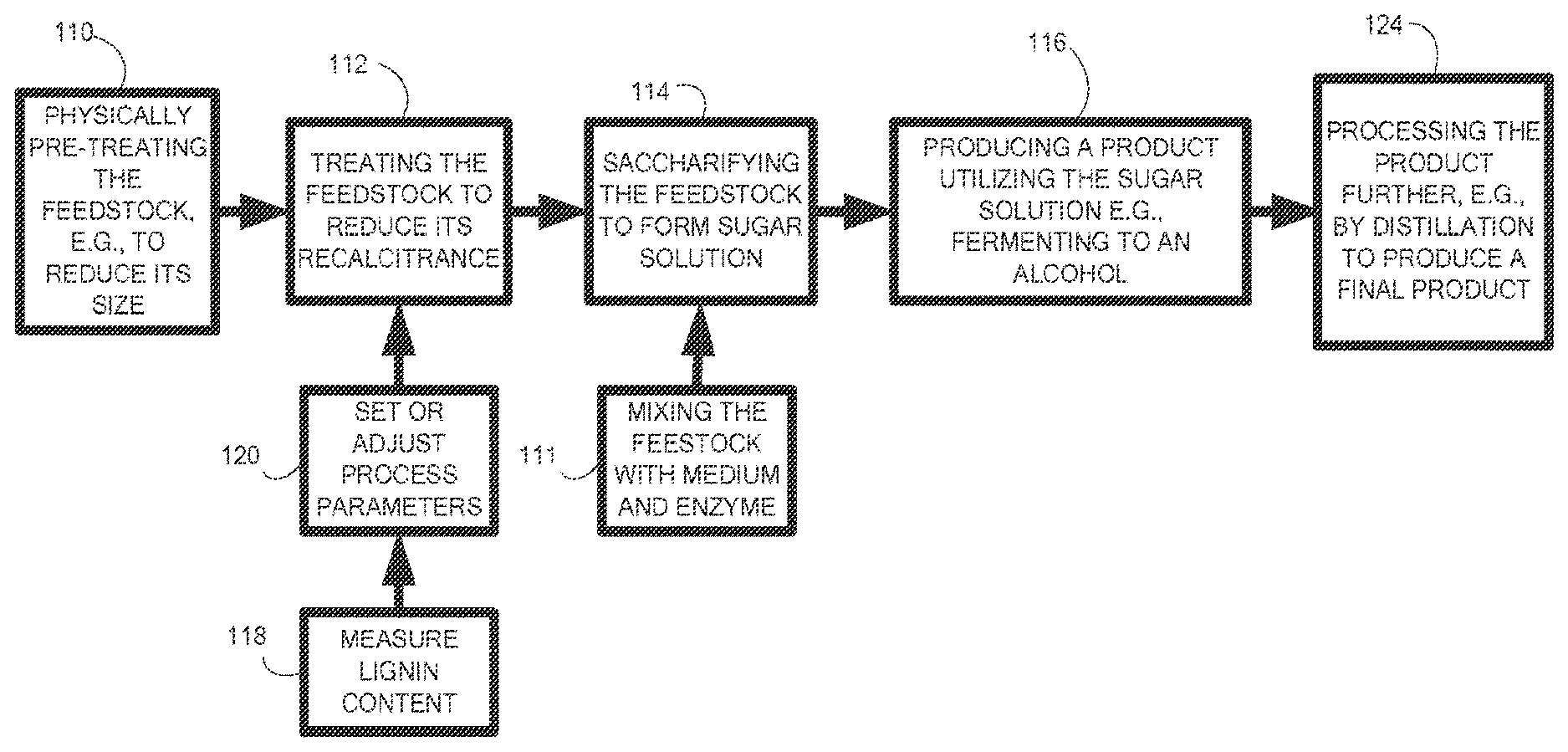
Referring to FIG. 1, processes for manufacturing sugar solutions and products derived therefrom include, for example, optionally mechanically treating a cellulosic and/or lignocellulosic feedstock 110. Before and/or after this treatment, the feedstock can be treated with another physical treatment, for example irradiation, to reduce, or further reduce its recalcitrance 112. A sugar solution is formed by saccharifying the feedstock 114 by, for example, the addition of one or more enzymes 111. A product can be derived from the sugar solution, for example, by fermentation to an alcohol 116. Further processing 124 can include purifying the solution, for example by distillation. If desired, the steps of measuring lignin content 118 and setting or adjusting process parameters based on this measurement 120 can be performed at various stages of the process, for example, as described in U.S. Pat. No. 8,415,122 issued Apr. 9, 2013, the complete disclosure of which is incorporated herein by reference.
The treatment step 112 can be irradiation with an electron beam. Several processes can occur in biomass when electrons from an electron beam interact with matter in inelastic collisions. For example, ionization of the material, chain scission of polymers in the material, cross linking of polymers in the material, oxidation of the material, generation of X-rays ("Bremsstrahlung") and vibrational excitation of molecules (e.g., phonon generation). Without being bound to a particular mechanism, the reduction in recalcitrance can be due to several of these inelastic collision effects, for example ionization, chain scission of polymers, oxidation and phonon generation. Some of the effects (e.g., especially X-ray generation), necessitate shielding and engineering barriers, for example, enclosing the irradiation processes in a concrete (or other radiation opaque material) vault. Another effect of irradiation, vibrational excitation, is equivalent to heating up the sample. Heating the sample by irradiation can help in recalcitrance reduction, but excessive heating can destroy the material, as will be explained below.
The adiabatic temperature rise (.DELTA.T) from adsorption of ionizing radiation is given by the equation: .DELTA.T=D/Cp: where D is the average dose in kGy, Cp is the heat capacity in J/g .degree. C., and .DELTA.T is the change in temperature in degrees Celsius. A typical dry biomass material will have a heat capacity close to 2. Wet biomass will have a higher heat capacity dependent on the amount of water since the heat capacity of water is very high (4.19 J/g .degree. C.). Metals have much lower heat capacities, for example 304 stainless steel has a heat capacity of 0.5 J/g .degree. C. The estimated temperature change due to the instant adsorption of radiation in a biomass and stainless steel for various doses of radiation is shown in Table 1. At the higher temperatures biomass will decompose causing extreme deviation from the estimated changes in temperature.
TABLE-US-00001 TABLE 1 Calculated Temperature increase for biomass and stainless steel. Dose (Mrad) Estimated Biomass .DELTA.T (.degree. C.) Steel .DELTA.T (.degree. C.) 10 50 200 50 250 (Decomposition) 1000 100 500 (Decomposition) 2000 150 750 (Decomposition) 3000 200 1000 (Decomposition) 4000
High temperatures can destroy and or modify the biopolymers in biomass so that the polymers (e.g., cellulose) are unsuitable for further processing. A biomass subjected to high temperatures can become dark, sticky and give off odors indicating decomposition. The stickiness can even make the material hard to convey. The odors can be unpleasant and be a safety issue. In fact, keeping the biomass below about 200.degree. C. has been found to be beneficial in the processes described herein (e.g., below about 190.degree. C., below about 180.degree. C., below about 170.degree. C., below about 160.degree. C., below about 150.degree. C., below about 140.degree. C., below about 130.degree. C., below about 120.degree. C., below about 110.degree. C., between about 60.degree. C. and 180.degree. C., between about 60.degree. C. and 160.degree. C., between about 60.degree. C. and 150.degree. C., between about 60.degree. C. and 140.degree. C., between about 60.degree. C. and 130.degree. C., between about 60.degree. C. and 120.degree. C., between about 80.degree. C. and 180.degree. C., between about 100.degree. C. and 180.degree. C., between about 120.degree. C. and 180.degree. C., between about 140.degree. C. and 180.degree. C., between about 160.degree. C. and 180.degree. C., between about 100.degree. C. and 140.degree. C., between about 80.degree. C. and 120.degree. C.).
It has been found that irradiation above about 10 Mrad is desirable for the processes described herein (e.g., reduction of recalcitrance). A high throughput is also desirable so that the irradiation does not become a bottle neck in processing the biomass. The treatment is governed by a Dose rate equation: M=FP/Dtime, where M is the mass of irradiated material (kg), F is the fraction of power that is adsorbed (unit less), P is the emitted power (kW=Voltage in MeV.times.Current in mA), time is the treatment time (sec) and D is the adsorbed dose (kGy). In an exemplary process where the fraction of adsorbed power is fixed, the Power emitted is constant and a set dosage is desired, the throughput (e.g., M, the biomass processed) can be increased by increasing the irradiation time. However, increasing the irradiation time without allowing the material to cool, can excessively heat the material as exemplified by the calculations shown above. Since biomass has a low thermal conductivity (less than about 0.1 Wm-1K-1), heat dissipation is slow, unlike, for example, metals (greater than about 10 Wm-1K-1) which can dissipate energy quickly as long as there is a heat sink to transfer the energy to.
A solution to the aforementioned contrasting issues, the need for a high radiation dose and rapid processing, without excessively heating the irradiated material, is to irradiate the biomass with one irradiator, allow the biomass to cool, and then irradiate the material with a second irradiator in a continuous manner. Higher throughput can be obtained by using even more irradiators (e.g., 3, 4, 5 or even more) but the costs of equipment and energy also increase.
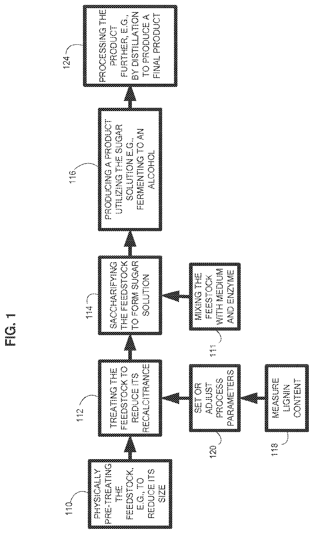
The systems and methods disclosed herein provide a possible solution for the safe and efficient processing of biomass. In particular, in order to increase the throughput of processing feedstock with irradiation, the processing can include applying to the feedstock more than one dose of radiation (e.g., more than one pass through a radiation beam). FIG. 2 shows a method to increase the throughput of processing feedstock with irradiation, for example, to reduce its recalcitrance, and utilizing two vaults. The two vaults can have a common wall. The process includes conveying the biomass into a first treatment vault 210. Within the first treatment vault, the biomass is irradiated while being conveyed by a conveyor 220. After the first irradiation, the biomass is conveyed out of the first treatment vault and into a second treatment vault 230. The biomass is irradiated in the second treatment vault 240. After the second treatment, the biomass is conveyed out of the second vault 250, and can be further processed and/or collected. The steps of conveying and irradiating can be repeated with a third, fourth or more vaults and conveyors. In another embodiment the material to be irradiated is conveyed to a single vault, irradiated, conveyed out of the vault, conveyed back into the same vault and then irradiated for a second time in the same vault. Permutation and combinations of these embodiments are also possible, for example irradiating twice in the first vault with or without conveying the material out of the vault, then conveying to another vault and irradiating the material. During the treatments in the vault, heat can be generated, for example, due to irradiation of a biomass and equipment as discussed. The heat can be removed from the biomass by a heat exchanger, for example a screw cooler or cooled conveyor. Optionally the heat can be utilized/transferred to other processes. For example, the heat 260 can be utilized for further processing of the material. For example, saccharification of an irradiated biomass material. In some instances, a biomass material can be irradiated and transferred without cooling directly into an aqueous solution, wherein the heated biomass aids in heating the water, for example by at least about 1.degree. C. (e.g., at least about 2.degree. C., at least 5.degree. C., at least about 10.degree. C., at least about 20.degree. C.).
For processes wherein the biomass is treated twice, the biomass needs to be conveyed or transported from one vault to the other between treatments. The energy utilized conveying the material between the first and second vault increases with the distance between the vaults. In addition, the material (e.g., building and/or equipment) costs are higher with increasing distance between the vaults. The least costs with respect to conveying the material would be in a configuration wherein sequential irradiation vaults are placed side by side with walls in contact.
In some embodiments, the biomass is allowed to cool between treatments, e.g., irradiations. This can be accomplished by the design of the two vaults. Therefore, in some embodiments, the distance between the vaults is sized to allow the biomass to cool at least about 5.degree. C. e.g., at least about 10.degree. C., at least about 15.degree. C., at least about 20.degree. C., at least about 30.degree. C., at least about 40.degree. C., at least about 50.degree. C. Cooling can be by heat exchange with the ambient environment and/or by a heat exchange system (e.g., cooling screw, cooled conveyor). The distance between the vaults can be determined by the cooling rate of the biomass and the conveying rate between irradiations.
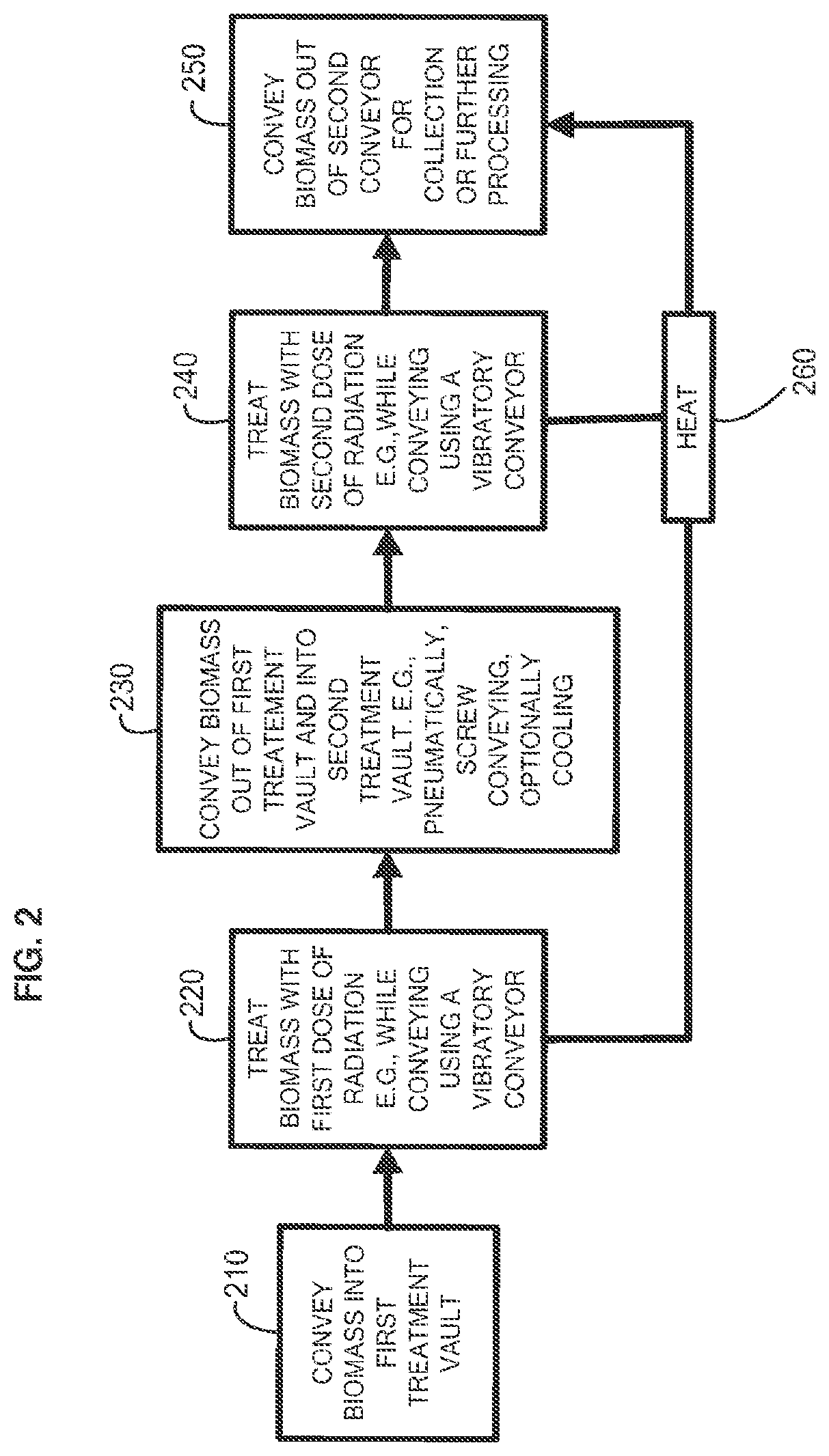
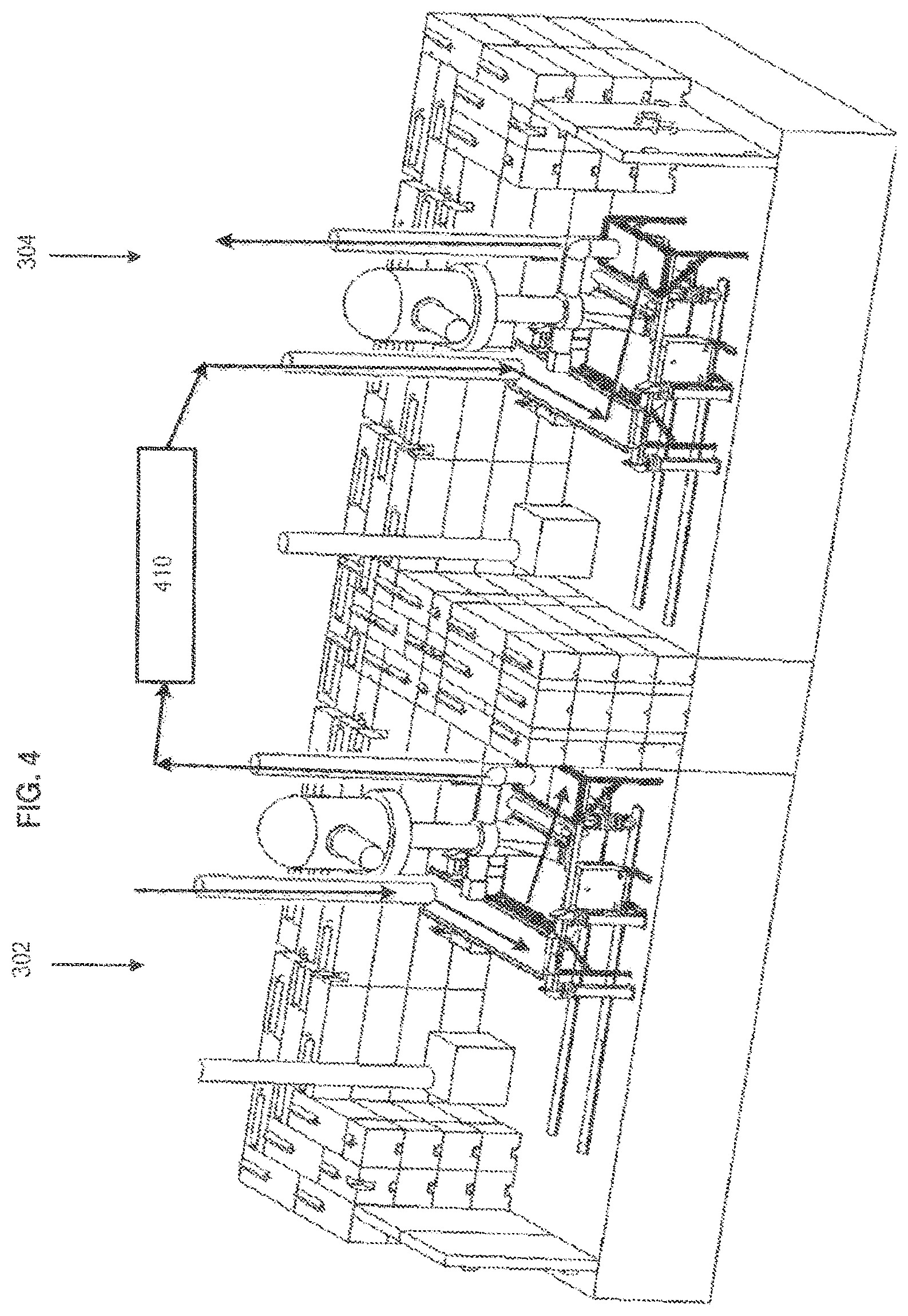
An alternative to having two discrete vaults side by side is shown in a perspective view in FIG. 3A. In this embodiment the two vaults share a common wall 310. This configuration allows the vaults to be in the closest proximity while still forming two irradiation vaults. The distance to convey the biomass material between vault 1 302 and vault 2 304 has also been minimized, providing cost advantages with respect to conveying the materials. In addition, by sharing a wall, material for construction of the walls has been reduced. Other embodiments include having three, four or more vaults sharing common walls. As more walls are shared between vaults, it is clear that the savings in material (e.g., building and/or equipment) would increase since arrangements with vaults sharing 2, 3 or even 4 walls can be envisioned.
Components and systems that can be used with the vaults will be outlined with reference to; the perspective view FIG. 3A, a front side view FIG. 3B, and a top side view FIG. 3C. An inlet 320 for a first enclosed conveyor 325 is situated at the end of pipe 327 where it is joined to conveyor 325. Material (e.g., biomass) is fed pneumatically by a pipe 327 through the inlet to the conveyor. The first conveyor is oriented perpendicularly and above the second conveyor 330 as shown. Material can be conveyed from the inlet of the first conveyor, traverse the length of the first conveyor and be then dumped onto the second conveyor. The first conveyor can have a cross cut conveying surface distal to the inlet 320. This cross can help to evenly distribute (e.g., dump, pore) the conveyed material onto the second conveyor 330. The second conveyor conveys the biomass material under the scan horn 340 and then dumps the material into the hopper (hopper 350 shown only in FIG. 3B through a rotary valve 360. The biomass is pneumatically conveyed out of the hopper through a tube 365 and passes through the ceiling of the vault where it can be sent to the inlet of the second vault.
Also shown in the FIGS. 3A, 3B and/or 3C are an electron beam accelerator 370 with a tube (vacuum tube) for accelerating electrons. The electron beam accelerator is mounted on and extends through the ceiling. A power source 380 for the electron beam accelerator is also mounted on the ceiling. An electrical conduit 382 from the power source to the electron beam accelerator is also shown. The conveyors and associated equipment are mounted on rails, 390 and 391, so that the conveyors can be moved out from under the irradiation equipment (e.g., the scan horn and electron beam accelerator). A vent system 395 for drawing out air from the vault is also shown. Similar systems and equipment can be used in the second vault 304. The vaults are built on a concrete slab 397 and the ceilings and walls are made of structurally resilient and radiation opaque materials (e.g., concrete, lead, stainless steel, rebar). Enclosures (not shown) can be provided within the vault to protect components of the conveying equipment or other equipment.
FIG. 4 is another perspective view showing a possible path of a material that is irradiated twice, once in vault 1, 302 and then in vault 2, 304. In addition to being conveyed from vault 1 to vault 2, the material can be further processed between the vaults. For example, at 410 the biomass can be cooled, comminuted, sampled, diverted and/or screened. For example, the materials can be conveyed, using cooled screw conveyors, cooled vibratory conveyors, pneumatic systems such as closed loop gas conveying systems.
Another possible configuration to allow multiple treatments and minimize conveying costs between irradiators is to have more than one electron beam device enclosed in a single vault. However, in such a configuration, if equipment in one of the vaults needs to be accessed then all the irradiators in that vault need to be taken off line for safety reasons. This can create a significant reduction in throughput and operator attention with concomitant financial losses. In embodiments with two or more vaults sharing two or more common walls, access to equipment associated with one irradiation device does not require other irradiation devices in other vaults to be taken off line. In these cases, the vault that is not being used can be by-passed, for example, by diverting the flow of biomass to other vaults with operating irradiators.
The flow of biomass into and between vaults can be re-directed as needed. For example, a first vault that was used for a first treatment of un-irradiated biomass can be bypassed and the biomass can be sent to a second vault that was being used for treating biomass for a second dose of radiation. The once treated biomass treated by this second vault can then be sent to a third vault where the biomass can be treated for a second time. The flow of biomass can also be diverted so that the biomass is sent to the same vault for treatment twice. This control of flow can be done by physically moving the necessary pneumatic systems such as pumps, blowers, dust bags and tubing. Alternatively, the pneumatic system can include a system of components interconnected between the vaults and the flow controlled by opening and closing valves and/or turning on or off pumps and/or turning on or off blowers.
The radiation dose applied in the first vault can be approximately the same as the radiation dose applied in the second vault. Alternatively, the radiation dose in two vaults can be different in each vault. For example, the radiation dose in a first vault can be less than about 50% of the total dose utilized in the irradiation (e.g., less than about 40%, less than about 30%, less than about 20%, less than about 10%). If more than two vaults are used in the irradiation, the radiation dose applied can be approximately the same in each vault or the radiation dose can be different in each vault.
The biomass can be treated continuously with the methods disclosed herein. In some embodiments the average rate of processing a biomass is more than about 500 lb/hr (e.g., more than about 1000 lb/hr, more than about 1500 lb/hr, more than about 2000 lb/hr, more than about 2500 lb/hr, more than about 3000 lb/hr, more than about 3500 lb/hr, more than about 4000 lb/hr, more than about 4500 lb/hr, more than more than about 5000 lb/hr, more than about 6000 lb/hr, more than about 10,000 lb/hr, more than about 15,000 lb/hr, more than about 20,000 lb/hr, more than about 25,000 lb/hr, for example; between about 1000 and 25,000 lb/hr, between about 1000 and 20,000 lb/hr, between about 1000 and 10,000 lb/hr, between about 1000 and 5000 lb/hr, between about 5000 and 25,000 lb/hr). The material can be processed at lower rates as well, e.g., below 500 lb/hr or below 100 lb/hr. The rates of conveying the material under an electron beam can vary greatly and independently between the irradiators in various vaults. For example, the conveying rate can be slowed down to increase the irradiation dose or increased to decrease the irradiation dose.
The vaults are designed to contain radiation as well as house the irradiation devices and associated equipment. Preferably the vaults are built with radiation opaque materials, for example concrete, lead, steel, soil or combinations of these. An example of a vault material is concrete which has a halving-thickness (the thickness to reduce the radiation by half) of 2.4''. Therefore, walls can be about 4 feet thick which would reduce radiation striking the walls to one millionth of the original strength. For a dose of 250 kGy applied inside the structure, the resulting radiation outside the structure, assuming an F-factor of 1.0, will be 0.25 microrem, well below safe limits. Walls can be thinner or thicker, for example, between 3 and 12 feet thick. In addition to walls, floors and ceilings, the vaults can have doors made of radiation opaque materials. The materials can be layered, for example, doors can be made as layers of 1'' lead over 6'' of steel over 1'' of lead.
Some more details and reiterations of processes for treating a feedstock that can be utilized, for example, with the embodiments already discussed above, or in other embodiments, are described in the following disclosures.
Radiation Treatment
The feedstock can be treated with radiation to modify its structure to reduce its recalcitrance. Such treatment can, for example, reduce the average molecular weight of the feedstock, change the crystalline structure of the feedstock, and/or increase the surface area and/or porosity of the feedstock . . . Radiation can be by, for example electron beam, ion beam, 100 nm to 28 nm ultraviolet (UV) light, gamma or X-ray radiation. Radiation treatments and systems for treatments are discussed in U.S. Pat. No. 8,142,620 and U.S. patent application Ser. No. 12/417,731, the entire disclosures of which are incorporated herein by reference.
Each form of radiation ionizes the biomass via particular interactions, as determined by the energy of the radiation. Heavy charged particles primarily ionize matter via Coulomb scattering; furthermore, these interactions produce energetic electrons that may further ionize matter. Alpha particles are identical to the nucleus of a helium atom and are produced by the alpha decay of various radioactive nuclei, such as isotopes of bismuth, polonium, astatine, radon, francium, radium, several actinides, such as actinium, thorium, uranium, neptunium, curium, californium, americium, and plutonium. Electrons interact via Coulomb scattering and bremsstrahlung radiation produced by changes in the velocity of electrons.
When particles are utilized, they can be neutral (uncharged), positively charged or negatively charged. When charged, the charged particles can bear a single positive or negative charge, or multiple charges, e.g., one, two, three or even four or more charges. In instances in which chain scission is desired to change the molecular structure of the carbohydrate containing material, positively charged particles may be desirable, in part, due to their acidic nature. When particles are utilized, the particles can have the mass of a resting electron, or greater, e.g., 500, 1000, 1500, or 2000 or more times the mass of a resting electron. For example, the particles can have a mass of from about 1 atomic unit to about 150 atomic units, e.g., from about 1 atomic unit to about 50 atomic units, or from about 1 to about 25, e.g., 1, 2, 3, 4, 5, 10, 12 or 15 atomic units.
Gamma radiation has the advantage of a significant penetration depth into a variety of material in the sample.
In embodiments in which the irradiating is performed with electromagnetic radiation, the electromagnetic radiation can have, e.g., energy per photon (in electron volts) of greater than 102 eV, e.g., greater than 103, 104, 105, 106, or even greater than 107 eV. In some embodiments, the electromagnetic radiation has energy per photon of between 104 and 107, e.g., between 105 and 106 eV. The electromagnetic radiation can have a frequency of, e.g., greater than 1016 Hz, greater than 1017 Hz, 1018, 1019, 1020, or even greater than 1021 Hz. In some embodiments, the electromagnetic radiation has a frequency of between 1018 and 1022 Hz, e.g., between 1019 to 1021 Hz.
Electron bombardment may be performed using an electron beam device that has a nominal energy of less than 10 MeV, e.g., less than 7 MeV, less than 5 MeV, or less than 2 MeV, e.g., from about 0.5 to 1.5 MeV, from about 0.8 to 1.8 MeV, or from about 0.7 to 1 MeV. In some implementations the nominal energy is about 500 to 800 keV.
The electron beam may have a relatively high total beam power (the combined beam power of all accelerating heads, or, if multiple accelerators are used, of all accelerators and all heads), e.g., at least 25 kW, e.g., at least 30, 40, 50, 60, 65, 70, 80, 100, 125, or 150 kW. In some cases, the power is even as high as 500 kW, 750 kW, or even 1000 kW or more. In some cases the electron beam has a beam power of 1200 kW or more, e.g., 1400, 1600, 1800, or even 3000 kW.
This high total beam power is usually achieved by utilizing multiple accelerating heads. For example, the electron beam device may include two, four, or more accelerating heads. The use of multiple heads, each of which has a relatively low beam power, prevents excessive temperature rise in the material, thereby preventing burning of the material, and also increases the uniformity of the dose through the thickness of the layer of material.
It is generally preferred that the bed of biomass material has a relatively uniform thickness. In some embodiments the thickness is less than about 1 inch (e.g., less than about 0.75 inches, less than about 0.5 inches, less than about 0.25 inches, less than about 0.1 inches, between about 0.1 and 1 inch, between about 0.2 and 0.3 inches).
It is desirable to treat the material as quickly as possible. In general, it is preferred that treatment be performed at a dose rate of greater than about 0.25 Mrad per second, e.g., greater than about 0.5, 0.75, 1, 1.5, 2, 5, 7, 10, 12, 15, or even greater than about 20 Mrad per second, e.g., about 0.25 to 2 Mrad per second. Higher dose rates allow a higher throughput for a target (e.g., the desired) dose. Higher dose rates generally require higher line speeds, to avoid thermal decomposition of the material. In one implementation, the accelerator is set for 3 MeV, 50 mA beam current, and the line speed is 24 feet/minute, for a sample thickness of about 20 mm (e.g., comminuted corn cob material with a bulk density of 0.5 g/cm3).
In some embodiments, electron bombardment is performed until the material receives a total dose of at least 0.1 Mrad, 0.25 Mrad, 1 Mrad, 5 Mrad, e.g., at least 10, 20, 30 or at least 40 Mrad. In some embodiments, the treatment is performed until the material receives a dose of from about 10 Mrad to about 50 Mrad, e.g., from about 20 Mrad to about 40 Mrad, or from about 25 Mrad to about 30 Mrad. In some implementations, a total dose of 25 to 35 Mrad is preferred, applied ideally over a couple of passes, e.g., at 5 Mrad/pass with each pass being applied for about one second. Cooling methods, systems and equipment can be used before, during, after and in between radiations, for example utilizing a cooling screw conveyor and/or a cooled vibratory conveyor.
Using multiple heads as discussed above, the material can be treated in multiple passes, for example, two passes at 10 to 20 Mrad/pass, e.g., 12 to 18 Mrad/pass, separated by a few seconds of cool-down, or three passes of 7 to 12 Mrad/pass, e.g., 5 to 20 Mrad/pass, 10 to 40 Mrad/pass, 9 to 11 Mrad/pass. As discussed herein, treating the material with several relatively low doses, rather than one high dose, tends to prevent overheating of the material and also increases dose uniformity through the thickness of the material. In some implementations, the material is stirred or otherwise mixed during or after each pass and then smoothed into a uniform layer again before the next pass, to further enhance treatment uniformity.
In some embodiments, electrons are accelerated to, for example, a speed of greater than 75 percent of the speed of light, e.g., greater than 85, 90, 95, or 99 percent of the speed of light.
In some embodiments, any processing described herein occurs on lignocellulosic material that remains dry as acquired or that has been dried, e.g., using heat and/or reduced pressure. For example, in some embodiments, the cellulosic and/or lignocellulosic material has less than about 25 wt. % retained water, measured at 25.degree. C. and at fifty percent relative humidity (e.g., less than about 20 wt. %, less than about 15 wt. %, less than about 14 wt. %, less than about 13 wt. %, less than about 12 wt. %, less than about 10 wt. %, less than about 9 wt. %, less than about 8 wt. %, less than about 7 wt. %, less than about 6 wt. %, less than about 5 wt. %, less than about 4 wt. %, less than about 3 wt. %, less than about 2 wt. %, less than about 1 wt. %, or less than about 0.5 wt. %.
In some embodiments, two or more ionizing sources can be used, such as two or more electron sources. For example, samples can be treated, in any order, with a beam of electrons, followed by gamma radiation and UV light having wavelengths from about 100 nm to about 280 nm. In some embodiments, samples are treated with three ionizing radiation sources, such as a beam of electrons, gamma radiation, and energetic UV light. The biomass is conveyed through the treatment zone where it can be bombarded with electrons.
It may be advantageous to repeat the treatment to more thoroughly reduce the recalcitrance of the biomass and/or further modify the biomass. In particular the process parameters can be adjusted after a first (e.g., second, third, fourth or more) pass depending on the recalcitrance of the material. In some embodiments, a conveyor can be used which includes a circular system where the biomass is conveyed multiple times through the various processes described above. In some other embodiments multiple treatment devices (e.g., electron beam generators) are used to treat the biomass multiple (e.g., 2, 3, 4 or more) times. In yet other embodiments, a single electron beam generator may be the source of multiple beams (e.g., 2, 3, 4 or more beams) that can be used for treatment of the biomass.
The effectiveness in changing the molecular/supermolecular structure and/or reducing the recalcitrance of the carbohydrate-containing biomass depends on the electron energy used and the dose applied, while exposure time depends on the power and dose. In some embodiments, the dose rate and total dose are adjusted so as not to destroy (e.g., char or burn) the biomass material. For example, the carbohydrates should not be damaged in the processing so that they can be released from the biomass intact, e.g. as monomeric sugars.
In some embodiments, the treatment (with any electron source or a combination of sources) is performed until the material receives a dose of at least about 0.05 Mrad, e.g., at least about 0.1, 0.25, 0.5, 0.75, 1.0, 2.5, 5.0, 7.5, 10.0, 15, 20, 25, 30, 40, 50, 60, 70, 80, 90, 100, 125, 150, 175, or 200 Mrad. In some embodiments, the treatment is performed until the material receives a dose of between 0.1-100 Mrad, 1-200, 5-200, 10-200, 5-150, 50-150 Mrad, 5-100, 5-50, 5-40, 10-50, 10-75, 15-50, 20-35 Mrad.
In some embodiments, relatively low doses of radiation are utilized, e.g., to increase the molecular weight of a cellulosic or lignocellulosic material (with any radiation source or a combination of sources described herein). For example, a dose of at least about 0.05 Mrad, e.g., at least about 0.1 Mrad or at least about 0.25, 0.5, 0.75. 1.0, 1.5, 2.0, 2.5, 3.0, 3.5, 4.0, or at least about 5.0 Mrad. In some embodiments, the irradiation is performed until the material receives a dose of between 0.1 Mrad and 2.0 Mrad, e.g., between 0.5 rad and 4.0 Mrad or between 1.0 Mrad and 3.0 Mrad.
It also can be desirable to irradiate from multiple directions, simultaneously or sequentially, in order to achieve a desired degree of penetration of radiation into the material. For example, depending on the density and moisture content of the material, such as wood, and the type of radiation source used (e.g., gamma or electron beam), the maximum penetration of radiation into the material may be only about 0.75 inch. In such a cases, a thicker section (up to 1.5 inch) can be irradiated by first irradiating the material from one side, and then turning the material over and irradiating from the other side. Irradiation from multiple directions can be particularly useful with electron beam radiation, which irradiates faster than gamma radiation but typically does not achieve as great a penetration depth.
Radiation Opaque Materials
As previously discussed, the invention can include processing the material in a vault and/or bunker that is constructed using radiation opaque materials. In some implementations, the radiation opaque materials are selected to be capable of shielding the components from X-rays with high energy (short wavelength), which can penetrate many materials. One important factor in designing a radiation shielding enclosure is the attenuation length of the materials used, which will determine the required thickness for a particular material, blend of materials, or layered structure. The attenuation length is the penetration distance at which the radiation is reduced to approximately 1/e (e=Euler's number) times that of the incident radiation. Although virtually all materials are radiation opaque if thick enough, materials containing a high compositional percentage (e.g., density) of elements that have a high Z value (atomic number) have a shorter radiation attenuation length and thus if such materials are used a thinner, lighter shielding can be provided. Examples of high Z value materials that are used in radiation shielding are tantalum and lead. Another important parameter in radiation shielding is the halving distance, which is the thickness of a particular material that will reduce gamma ray intensity by 50%. As an example for X-ray radiation with an energy of 0.1 MeV the halving thickness is about 15.1 mm for concrete and about 2.7 mm for lead, while with an X-ray energy of 1 MeV the halving thickness for concrete is about 44.45 mm and for lead is about 7.9 mm. Radiation opaque materials can be materials that are thick or thin so long as they can reduce the radiation that passes through to the other side. Thus, if it is desired that a particular enclosure have a low wall thickness, e.g., for light weight or due to size constraints, the material chosen should have a sufficient Z value and/or attenuation length so that its halving length is less than or equal to the desired wall thickness of the enclosure.
In some cases, the radiation opaque material may be a layered material, for example, having a layer of a higher Z value material, to provide good shielding, and a layer of a lower Z value material to provide other properties (e.g., structural integrity, impact resistance, etc.). In some cases, the layered material may be a "graded-Z" laminate, e.g., including a laminate in which the layers provide a gradient from high-Z through successively lower-Z elements. In some cases the radiation opaque materials can be interlocking blocks, for example, lead and/or concrete blocks can be supplied by NELCO Worldwide (Burlington, Mass.). For example, the blocks can include a dry-joint design so as to be reconfigurable and modular. For example, some materials that can be used include concrete blocks, MEGASHILED.TM. MODULAR BLOCK, n-Series Lead Brick. For example, the radiation opaque materials can be high density materials e.g., having densities greater than about 100 lbs/cu ft, greater than about 200 lbs for cu ft or even greater than about 300 lb/cu ft. For example, NELCO (Burlington, Mass.) concrete blocks having about 147 lbs/cu ft, 250 lb/cu ft, 288 lb/cu ft and 300 lb/cu ft. The materials can be used to provide an entirely new construction or upgrade existing facilities.
A radiation opaque material can reduce the radiation passing through a structure (e.g., a wall, door, ceiling, enclosure, a series of these or combinations of these) formed of the material by about at least about 10%, (e.g., at least about 20%, at least about 30%, at least about 40%, at least about 50%, at least about 60%, at least about 70%, at least about 80%, at least about 90%, at least about 95%, at least about 96%, at least about 97%, at least about 98%, at least about 99%, at least about 99.9%, at least about 99.99%, at least about 99.999%) as compared to the incident radiation. Therefore, an enclosure made of a radiation opaque material can reduce the exposure of equipment/system/components by the same amount. Radiation opaque materials can include stainless steel, metals with Z values above 25 (e.g., lead, iron), concrete, dirt, sand and combinations thereof. Radiation opaque materials can include a barrier in the direction of the incident radiation of at least about 1 mm (e.g., 5 mm, 10 mm, 5 cm, 10 cm, 100 cm, 1 m and even at least about 10 m).
Radiation Sources
The type of radiation determines the kinds of radiation sources used as well as the radiation devices and associated equipment. The methods, systems and equipment described herein, for example for treating materials with radiation, can utilized sources as described herein as well as any other useful source.
Sources of gamma rays include radioactive nuclei, such as isotopes of cobalt, calcium, technetium, chromium, gallium, indium, iodine, iron, krypton, samarium, selenium, sodium, thallium, and xenon.
Sources of X-rays include electron beam collision with metal targets, such as tungsten or molybdenum or alloys, or compact light sources, such as those produced commercially by Lyncean.
Alpha particles are identical to the nucleus of a helium atom and are produced by the alpha decay of various radioactive nuclei, such as isotopes of bismuth, polonium, astatine, radon, francium, radium, several actinides, such as actinium, thorium, uranium, neptunium, curium, californium, americium, and plutonium.
Sources for ultraviolet radiation include deuterium or cadmium lamps.
Sources for infrared radiation include sapphire, zinc, or selenide window ceramic lamps.
Sources for microwaves include klystrons, Slevin type RF sources, or atom beam sources that employ hydrogen, oxygen, or nitrogen gases.
Accelerators used to accelerate the particles (e.g., electrons or ions) can be DC (e.g., electrostatic DC or electrodynamic DC), RF linear, magnetic induction linear or continuous wave. For example, various irradiating devices may be used in the methods disclosed herein, including field ionization sources, electrostatic ion separators, field ionization generators, thermionic emission sources, microwave discharge ion sources, recirculating or static accelerators, dynamic linear accelerators, van de Graaff accelerators, Cockroft Walton accelerators (e.g., PELLETRON.RTM. accelerators), LINACS, Dynamitrons (e.g., DYNAMITRON.RTM. accelerators), cyclotrons, synchrotrons, betatrons, transformer-type accelerators, microtrons, plasma generators, cascade accelerators, and folded tandem accelerators. For example, cyclotron type accelerators are available from IBA, Belgium, such as the RHODOTRON.TM. system, while DC type accelerators are available from RDI, now IBA Industrial, such as the DYNAMITRON.RTM.. Other suitable accelerator systems include, for example: DC insulated core transformer (ICT) type systems, available from Nissin High Voltage, Japan; S-band LINACs, available from L3-PSD (USA), Linac Systems (France), Mevex (Canada), and Mitsubishi Heavy Industries (Japan); L-band LINACs, available from Iotron Industries (Canada); and ILU-based accelerators, available from Budker Laboratories (Russia). Ions and ion accelerators are discussed in Introductory Nuclear Physics, Kenneth S. Krane, John Wiley & Sons, Inc. (1988), Krsto Prelec, FIZIKA B 6 (1997) 4, 177-206, Chu, William T., "Overview of Light-Ion Beam Therapy", Columbus-Ohio, ICRU-IAEA Meeting, 18-20 Mar. 2006, Iwata, Y. et al., "Alternating-Phase-Focused 1H-DTL for Heavy-Ion Medical Accelerators", Proceedings of EPAC 2006, Edinburgh, Scotland, and Leitner, C. M. et al., "Status of the Superconducting ECR Ion Source Venus", Proceedings of EPAC 2000, Vienna, Austria. Some particle accelerators and their uses are disclosed, for example, in U.S. Pat. No. 7,931,784 to Medoff, the complete disclosure of which is incorporated herein by reference.
Electrons may be produced by radioactive nuclei that undergo beta decay, such as isotopes of iodine, cesium, technetium, and iridium. Alternatively, an electron gun can be used as an electron source via thermionic emission and accelerated through an accelerating potential. An electron gun generates electrons, which are then accelerated through a large potential (e.g., greater than about 500 thousand, greater than about 1 million, greater than about 2 million, greater than about 5 million, greater than about 6 million, greater than about 7 million, greater than about 8 million, greater than about 9 million, or even greater than 10 million volts) and then scanned magnetically in the x-y plane, where the electrons are initially accelerated in the z direction down the accelerator tube and extracted through a foil window. Scanning the electron beams is useful for increasing the irradiation surface when irradiating materials, e.g., a biomass, that is conveyed through the scanned beam. Scanning the electron beam also distributes the thermal load homogenously on the window and helps reduce the foil window rupture due to local heating by the electron beam. Window foil rupture is a cause of significant down-time due to subsequent necessary repairs and re-starting the electron gun.
Various other irradiating devices may be used in the methods disclosed herein, including field ionization sources, electrostatic ion separators, field ionization generators, thermionic emission sources, microwave discharge ion sources, recirculating or static accelerators, dynamic linear accelerators, van de Graaff accelerators, and folded tandem accelerators. Such devices are disclosed, for example, in U.S. Pat. No. 7,931,784 to Medoff, the complete disclosure of which is incorporated herein by reference.
A beam of electrons can be used as the radiation source. A beam of electrons has the advantages of high dose rates (e.g., 1, 5, or even 10 Mrad per second), high throughput, less containment, and less confinement equipment. Electron beams can also have high electrical efficiency (e.g., 80%), allowing for lower energy usage relative to other radiation methods, which can translate into a lower cost of operation and lower greenhouse gas emissions corresponding to the smaller amount of energy used. Electron beams can be generated, e.g., by electrostatic generators, cascade generators, transformer generators, low energy accelerators with a scanning system, low energy accelerators with a linear cathode, linear accelerators, and pulsed accelerators.
Electrons can also be more efficient at causing changes in the molecular structure of carbohydrate-containing materials, for example, by the mechanism of chain scission. In addition, electrons having energies of 0.5-10 MeV can penetrate low density materials, such as the biomass materials described herein, e.g., materials having a bulk density of less than 0.5 g/cm.sup.3, and a depth of 0.3-10 cm. Electrons as an ionizing radiation source can be useful, e.g., for relatively thin piles, layers or beds of materials, e.g., less than about 0.5 inch, e.g., less than about 0.4 inch, 0.3 inch, 0.25 inch, or less than about 0.1 inch. In some embodiments, the energy of each electron of the electron beam is from about 0.3 MeV to about 2.0 MeV (million electron volts), e.g., from about 0.5 MeV to about 1.5 MeV, or from about 0.7 MeV to about 1.25 MeV. Methods of irradiating materials are discussed in U.S. Pat. App. Pub. 2012/0100577 A1, filed Oct. 18, 2011, the entire disclosure of which is herein incorporated by reference.
Electron beam irradiation devices may be procured commercially or built. For example elements or components such inductors, capacitors, casings, power sources, cables, wiring, voltage control systems, current control elements, insulating material, microcontrollers and cooling equipment can be purchased and assembled into a device. Optionally, a commercial device can be modified and/or adapted. For example, devices and components can be purchased from any of the commercial sources described herein including Ion Beam Applications (Louvain-la-Neuve, Belgium), Wasik Associates Inc. (Dracut, Mass.), NHV Corporation (Japan), the Titan Corporation (San Diego, Calif.), Vivirad High Voltage Corp (Billerica, Mass.) and/or Budker Laboratories (Russia). Typical electron energies can be 0.5 MeV, 1 MeV, 2 MeV, 4.5 MeV, 7.5 MeV, or 10 MeV. Typical electron beam irradiation device power can be 1 kW, 5 kW, 10 kW, 20 kW, 50 kW, 60 kW, 70 kW, 80 kW, 90 kW, 100 kW, 125 kW, 150 kW, 175 kW, 200 kW, 250 kW, 300 kW, 350 kW, 400 kW, 450 kW, 500 kW, 600 kW, 700 kW, 800 kW, 900 kW or even 1000 kW. Accelerators that can be used include NHV irradiators medium energy series EPS-500 (e.g., 500 kV accelerator voltage and 65, 100 or 150 mA beam current), EPS-800 (e.g., 800 kV accelerator voltage and 65 or 100 mA beam current), or EPS-1000 (e.g., 1000 kV accelerator voltage and 65 or 100 mA beam current). Also, accelerators from NHV's high energy series can be used such as EPS-1500 (e.g., 1500 kV accelerator voltage and 65 mA beam current), EPS-2000 (e.g., 2000 kV accelerator voltage and 50 mA beam current), EPS-3000 (e.g., 3000 kV accelerator voltage and 50 mA beam current) and EPS-5000 (e.g., 5000 and 30 mA beam current).
Tradeoffs in considering electron beam irradiation device power specifications include cost to operate, capital costs, depreciation, and device footprint. Tradeoffs in considering exposure dose levels of electron beam irradiation would be energy costs and environment, safety, and health (ESH) concerns. Typically, generators are housed in a vault, e.g., of lead or concrete, especially for production from X-rays that are generated in the process. Tradeoffs in considering electron energies include energy costs.
The electron beam irradiation device can produce either a fixed beam or a scanning beam. A scanning beam may be advantageous with large scan sweep length and high scan speeds, as this would effectively replace a large, fixed beam width. Further, available sweep widths of 0.5 m, 1 m, 2 m or more are available. The scanning beam is preferred in most embodiments described herein because of the larger scan width and reduced possibility of local heating and failure of the windows.
Electron Guns--Windows
The extraction system for an electron accelerator can include two window foils. The cooling gas in the two foil window extraction system can be a purge gas or a mixture, for example air, or a pure gas. In one embodiment the gas is an inert gas such as nitrogen, argon, helium and or carbon dioxide. It is preferred to use a gas rather than a liquid since energy losses to the electron beam are minimized. Mixtures of pure gas can also be used, either pre-mixed or mixed in line prior to impinging on the windows or in the space between the windows. The cooling gas can be cooled, for example, by using a heat exchange system (e.g., a chiller) and/or by using boil off from a condensed gas (e.g., liquid nitrogen, liquid helium). Window foils are described in PCT/US2013/64332 filed Oct. 10, 2013 the full disclosure of which is incorporated by reference herein.
Electron Guns--Beam Stops
In some embodiments the systems and methods include a beam stop (e.g., a shutter). For example, the beam stop can be used to quickly stop or reduce the irradiation of material without powering down the electron beam device. Alternatively the beam stop can be used while powering up the electron beam, e.g., the beam stop can stop the electron beam until a beam current of a desired level is achieved. The beam stop can be placed between the primary foil window and a secondary foil window. For example, the beam stop can be mounted so that it is movable, that is, so that it can be moved into and out of the beam path. Even partial coverage of the beam can be used, for example, to control the dose of irradiation. The beam stop can be mounted to the floor, to a conveyor for the biomass, to a wall, to the radiation device (e.g., at the scan horn), or to any structural support. Preferably the beam stop is fixed in relation to the scan horn so that the beam can be effectively controlled by the beam stop. The beam stop can incorporate a hinge, a rail, wheels, slots, or other means allowing for its operation in moving into and out of the beam. The beam stop can be made of any material that will stop at least 5% of the electrons, e.g., at least 10%, 20%, 30%, 40%, 50%, 60%, 70%, at least 80%, 85%, 90%, 91%, 92%, 93%, 94%, 95%, 96%, 97%, 98%, 99% or even about 100% of the electrons.
The beam stop can be made of a metal including, but not limited to, stainless steel, lead, iron, molybdenum, silver, gold, titanium, aluminum, tin, or alloys of these, or laminates (layered materials) made with such metals (e.g., metal-coated ceramic, metal-coated polymer, metal-coated composite, multilayered metal materials).
The beam stop can be cooled, for example, with a cooling fluid such as an aqueous solution or a gas. The beam stop can be partially or completely hollow, for example with cavities. Interior spaces of the beam stop can be used for cooling fluids and gases. The beam stop can be of any shape, including flat, curved, round, oval, square, rectangular, beveled and wedged shapes.
The beam stop can have perforations so as to allow some electrons through, thus controlling (e.g., reducing) the levels of radiation across the whole area of the window, or in specific regions of the window. The beam stop can be a mesh formed, for example, from fibers or wires. Multiple beam stops can be used, together or independently, to control the irradiation. The beam stop can be remotely controlled, e.g., by radio signal or hard wired to a motor for moving the beam into or out of position.
Beam Dumps
The embodiments disclosed herein can also include a beam dump when utilizing a radiation treatment. A beam dump's purpose is to safely absorb a beam of charged particles. Like a beam stop, a beam dump can be used to block the beam of charged particles. However, a beam dump is much more robust than a beam stop, and is intended to block the full power of the electron beam for an extended period of time. They are often used to block the beam as the accelerator is powering up.
Beam dumps are also designed to accommodate the heat generated by such beams, and are usually made from materials such as copper, aluminum, carbon, beryllium, tungsten, or mercury. Beam dumps can be cooled, for example, using a cooling fluid that can be in thermal contact with the beam dump.
Biomass Materials
Lignocellulosic materials include, but are not limited to, wood, particle board, forestry wastes (e.g., sawdust, aspen wood, wood chips), grasses, (e.g., switchgrass, miscanthus, cord grass, reed canary grass), grain residues, (e.g., rice hulls, oat hulls, wheat chaff, barley hulls), agricultural waste (e.g., silage, canola straw, wheat straw, barley straw, oat straw, rice straw, jute, hemp, flax, bamboo, sisal, abaca, corn cobs, corn stover, soybean stover, corn fiber, alfalfa, hay, coconut hair), sugar processing residues (e.g., bagasse, beet pulp, agave bagasse), algae, seaweed, manure, sewage, and mixtures of any of these.
In some cases, the lignocellulosic material includes corncobs. Ground or hammermilled corncobs can be spread in a layer of relatively uniform thickness for irradiation, and after irradiation are easy to disperse in the medium for further processing. To facilitate harvest and collection, in some cases the entire corn plant is used, including the corn stalk, corn kernels, and in some cases even the root system of the plant.
Advantageously, no additional nutrients (other than a nitrogen source, e.g., urea or ammonia) are required during fermentation of corncobs or cellulosic or lignocellulosic materials containing significant amounts of corncobs.
Corncobs, before and after comminution, are also easier to convey and disperse, and have a lesser tendency to form explosive mixtures in air than other cellulosic or lignocellulosic materials such as hay and grasses.
Cellulosic materials include, for example, paper, paper products, paper waste, paper pulp, pigmented papers, loaded papers, coated papers, filled papers, magazines, printed matter (e.g., books, catalogs, manuals, labels, calendars, greeting cards, brochures, prospectuses, newsprint), printer paper, polycoated paper, card stock, cardboard, paperboard, materials having a high .alpha.-cellulose content such as cotton, and mixtures of any of these. For example, paper products as described in U.S. application Ser. No. 13/396,365 ("Magazine Feedstocks" by Medoff et al., filed Feb. 14, 2012), the full disclosure of which is incorporated herein by reference.
Cellulosic materials can also include lignocellulosic materials which have been partially or fully de-lignified.
In some instances other biomass materials can be utilized, for example starchy materials. Starchy materials include starch itself, e.g., corn starch, wheat starch, potato starch or rice starch, a derivative of starch, or a material that includes starch, such as an edible food product or a crop. For example, the starchy material can be arracacha, buckwheat, banana, barley, cassava, kudzu, ocra, sago, sorghum, regular household potatoes, sweet potato, taro, yams, or one or more beans, such as favas, lentils or peas. Blends of any two or more starchy materials are also starchy materials. Mixtures of starchy, cellulosic and or lignocellulosic materials can also be used. For example, a biomass can be an entire plant, a part of a plant or different parts of a plant, e.g., a wheat plant, cotton plant, a corn plant, rice plant or a tree. The starchy materials can be treated by any of the methods described herein.
Microbial materials that can be used as feedstock can include, but are not limited to, any naturally occurring or genetically modified microorganism or organism that contains or is capable of providing a source of carbohydrates (e.g., cellulose), for example, protists, e.g., animal protists (e.g., protozoa such as flagellates, amoeboids, ciliates, and sporozoa) and plant protists (e.g., algae such alveolates, chlorarachniophytes, cryptomonads, euglenids, glaucophytes, haptophytes, red algae, stramenopiles, and viridaeplantae). Other examples include seaweed, plankton (e.g., macroplankton, mesoplankton, microplankton, nanoplankton, picoplankton, and femptoplankton), phytoplankton, bacteria (e.g., gram positive bacteria, gram negative bacteria, and extremophiles), yeast and/or mixtures of these. In some instances, microbial biomass can be obtained from natural sources, e.g., the ocean, lakes, bodies of water, e.g., salt water or fresh water, or on land. Alternatively or in addition, microbial biomass can be obtained from culture systems, e.g., large scale dry and wet culture and fermentation systems.
In other embodiments, the biomass materials, such as cellulosic, starchy and lignocellulosic feedstock materials, can be obtained from transgenic microorganisms and plants that have been modified with respect to a wild type variety. Such modifications may be, for example, through the iterative steps of selection and breeding to obtain desired traits in a plant. Furthermore, the plants can have had genetic material removed, modified, silenced and/or added with respect to the wild type variety. For example, genetically modified plants can be produced by recombinant DNA methods, where genetic modifications include introducing or modifying specific genes from parental varieties, or, for example, by using transgenic breeding wherein a specific gene or genes are introduced to a plant from a different species of plant and/or bacteria. Another way to create genetic variation is through mutation breeding wherein new alleles are artificially created from endogenous genes. The artificial genes can be created by a variety of ways including treating the plant or seeds with, for example, chemical mutagens (e.g., using alkylating agents, epoxides, alkaloids, peroxides, formaldehyde), irradiation (e.g., X-rays, gamma rays, neutrons, beta particles, alpha particles, protons, deuterons, UV radiation) and temperature shocking or other external stressing and subsequent selection techniques. Other methods of providing modified genes is through error prone PCR and DNA shuffling followed by insertion of the desired modified DNA into the desired plant or seed. Methods of introducing the desired genetic variation in the seed or plant include, for example, the use of a bacterial carrier, biolistics, calcium phosphate precipitation, electroporation, gene splicing, gene silencing, lipofection, microinjection and viral carriers. Additional genetically modified materials have been described in U.S. application Ser. No. 13/396,369 filed Feb. 14, 2012 (published Feb. 28, 2013) the full disclosure of which is incorporated herein by reference.
Any of the methods described herein can be practiced with mixtures of any biomass materials described herein.
Other Materials
Other materials (e.g., natural or synthetic materials), for example polymers, can be treated and/or made utilizing the methods, equipment and systems described hererin. For example polyethylene (e.g., linear low density ethylene and high density polyethylene), polystyrenes, sulfonated polystyrenes, poly(vinyl chloride), polyesters (e.g., nylons, DACRON.TM., KODEL.TM.), polyalkylene esters, poly vinyl esters, polyamides (e.g., KEVLAR.TM.) polyethylene terephthalate, cellulose acetate, acetal, poly acrylonitrile, polycarbonates (e.g., LEXAN.TM.), acrylics [e.g., poly(methyl methacrylate), poly(methyl methacrylate), polyacrylnitriles], Poly urethanes, polypropylene, poly butadiene, polyisobutylene, polyacrylonitrile, polychloroprene (e.g. neoprene), poly(cis-1,4-isoprene) [e.g., natural rubber], poly(trans-1,4-isoprene) [e.g., gutta percha], phenol formaldehyde, melamine formaldehyde, epoxides, polyesters, poly amines, polycarboxylic acids, polylactic acids, polyvinyl alcohols, polyanhydrides, poly fluoro carbons (e.g., TEFLON.TM.), silicons (e.g., silicone rubber), polysilanes, poly ethers (e.g., polyethylene oxide, polypropylene oxide), waxes, oils and mixtures of these. Also included are plastics, rubbers, elastomers, fibers, waxes, gels, oils, adhesives, thermoplastics, thermosets, biodegradable polymers, resins made with these polymers, other polymers, other materials and combinations thereof. The polymers can be made by any useful method including cationic polymerization, anionic polymerization, radical polymerization, metathesis polymerization, ring opening polymerization, graft polymerization, addition polymerization. In some cases the treatments disclosed herein can be used, for example, for radically initiated graft polymerization and cross linking. Composites of polymers, for example with glass, metals, biomass (e.g., fibers, particles), ceramics can also be treated and/or made.
Other materials that can be treated by using the methods, systems and equipment disclosed herein are ceramic materials, minerals, metals, inorganic compounds. For example, silicon and germanium crystals, silicon nitrides, metal oxides, semiconductors, insulators, cements and or conductors.
In addition, manufactured multipart or shaped materials (e.g., molded, extruded, welded, riveted, layered or combined in any way) can be treated, for example cables, pipes, boards, enclosures, integrated semiconductor chips, circuit boards, wires, tires, windows, laminated materials, gears, belts, machines, combinations of these. For example, treating a material by the methods described herein can modify the surfaces, for example, making them susceptible to further functionalization, combinations (e.g., welding) and/or treatment can cross link the materials.
Biomass Material Preparation--Mechanical Treatments
The biomass can be in a dry form, for example with less than about 35% moisture content (e.g., less than about 20%, less than about 15%, less than about 10% less than about 5%, less than about 4%, less than about 3%, less than about 2% or even less than about 1%). The biomass can also be delivered in a wet state, for example as a wet solid, a slurry or a suspension with at least about 10 wt. % solids (e.g., at least about 20 wt. %, at least about 30 wt. %, at least about 40 wt. %, at least about 50 wt. %, at least about 60 wt. %, at least about 70 wt. %).
The processes disclosed herein can utilize low bulk density materials, for example cellulosic or lignocellulosic feedstocks that have been physically pretreated to have a bulk density of less than about 0.75 g/cm3, e.g., less than about 0.7, 0.65, 0.60, 0.50, 0.35, 0.25, 0.20, 0.15, 0.10, 0.05 or less, e.g., less than about 0.025 g/cm3. Bulk density is determined using ASTM D1895B. Briefly, the method involves filling a measuring cylinder of known volume with a sample and obtaining a weight of the sample. The bulk density is calculated by dividing the weight of the sample in grams by the known volume of the cylinder in cubic centimeters. If desired, low bulk density materials can be densified, for example, by methods described in U.S. Pat. No. 7,971,809 to Medoff, the full disclosure of which is hereby incorporated by reference.
In some cases, the pre-treatment processing includes screening of the biomass material. Screening can be through a mesh or perforated plate with a desired opening size, for example, less than about 6.35 mm (1/4 inch, 0.25 inch), (e.g., less than about 3.18 mm (1/8 inch, 0.125 inch), less than about 1.59 mm ( 1/16 inch, 0.0625 inch), is less than about 0.79 mm ( 1/32 inch, 0.03125 inch), e.g., less than about 0.51 mm ( 1/50 inch, 0.02000 inch), less than about 0.40 mm ( 1/64 inch, 0.015625 inch), less than about 0.23 mm (0.009 inch), less than about 0.20 mm ( 1/128 inch, 0.0078125 inch), less than about 0.18 mm (0.007 inch), less than about 0.13 mm (0.005 inch), or even less than about 0.10 mm ( 1/256 inch, 0.00390625 inch)). In one configuration, the desired biomass falls through the perforations or screen and thus biomass larger than the perforations or screen are not irradiated. These larger materials can be re-processed, for example by comminuting, or they can simply be removed from processing. In another configuration material that is larger than the perforations is irradiated and the smaller material is removed by the screening process or recycled. In this kind of a configuration, the conveyor itself (for example, a part of the conveyor) can be perforated or made with a mesh. For example, in one particular embodiment the biomass material may be wet and the perforations or mesh allow water to drain away from the biomass before irradiation.
Screening of material can also be by a manual method, for example, by an operator or mechanoid (e.g., a robot equipped with a color, reflectivity or other sensor) that removes unwanted material. Screening can also be by magnetic screening wherein a magnet is disposed near the conveyed material and the magnetic material is removed magnetically.
Optional pre-treatment processing can include heating the material. For example, a portion of a conveyor conveying the biomass or other material can be sent through a heated zone. The heated zone can be created, for example, by IR radiation, microwaves, combustion (e.g., gas, coal, oil, biomass), resistive heating and/or inductive coils. The heat can be applied from at least one side or more than one side, can be continuous or periodic and can be for only a portion of the material or all the material. For example, a portion of the conveying trough can be heated by use of a heating jacket. Heating can be, for example, for the purpose of drying the material. In the case of drying the material, this can also be facilitated, with or without heating, by the movement of a gas (e.g., air, oxygen, nitrogen, He, CO2, Argon) over and/or through the biomass as it is being conveyed.
Optionally, pre-treatment processing can include cooling the material. Cooling material is described in U.S. Pat. No. 7,900,857 to Medoff, the disclosure of which in incorporated herein by reference. For example, cooling can be by supplying a cooling fluid, for example water (e.g., with glycerol), or nitrogen (e.g., liquid nitrogen) to the bottom of the conveying trough. Alternatively, a cooling gas, for example, chilled nitrogen can be blown over the biomass materials or under the conveying system.
Another optional pre-treatment processing method can include adding a material to the biomass or other feedstocks. The additional material can be added by, for example, by showering, sprinkling and or pouring the material onto the biomass as it is conveyed. Materials that can be added include, for example, metals, ceramics and/or ions as described in U.S. Pat. App. Pub. 2010/0105119 A1 (filed Oct. 26, 2009) and U.S. Pat. App. Pub. 2010/0159569 A1 (filed Dec. 16, 2009), the entire disclosures of which are incorporated herein by reference. Optional materials that can be added include acids and bases. Other materials that can be added are oxidants (e.g., peroxides, chlorates), polymers, polymerizable monomers (e.g., containing unsaturated bonds), water, catalysts, enzymes and/or organisms. Materials can be added, for example, in pure form, as a solution in a solvent (e.g., water or an organic solvent) and/or as a solution. In some cases the solvent is volatile and can be made to evaporate e.g., by heating and/or blowing gas as previously described. The added material may form a uniform coating on the biomass or be a homogeneous mixture of different components (e.g., biomass and additional material). The added material can modulate the subsequent irradiation step by increasing the efficiency of the irradiation, damping the irradiation or changing the effect of the irradiation (e.g., from electron beams to X-rays or heat). The method may have no impact on the irradiation but may be useful for further downstream processing. The added material may help in conveying the material, for example, by lowering dust levels.
Biomass can be delivered to a conveyor (e.g., vibratory conveyors used in the vaults herein described) by a belt conveyor, a pneumatic conveyor, a screw conveyor, a hopper, a pipe, manually or by a combination of these. The biomass can, for example, be dropped, poured and/or placed onto the conveyor by any of these methods. In some embodiments the material is delivered to the conveyor using an enclosed material distribution system to help maintain a low oxygen atmosphere and/or control dust and fines. Lofted or air suspended biomass fines and dust are undesirable because these can form an explosion hazard or damage the window foils of an electron gun (if such a device is used for treating the material).
The material can be leveled to form a uniform thickness between about 0.0312 and 5 inches (e.g., between about 0.0625 and 2.000 inches, between about 0.125 and 1 inches, between about 0.125 and 0.5 inches, between about 0.3 and 0.9 inches, between about 0.2 and 0.5 inches between about 0.25 and 1.0 inches, between about 0.25 and 0.5 inches, 0.100+/-0.025 inches, 0.150+/-0.025 inches, 0.200+/-0.025 inches, 0.250+/-0.025 inches, 0.300+/-0.025 inches, 0.350+/-0.025 inches, 0.400+/-0.025 inches, 0.450+/-0.025 inches, 0.500+/-0.025 inches, 0.550+/-0.025 inches, 0.600+/-0.025 inches, 0.700+/-0.025 inches, 0.750+/-0.025 inches, 0.800+/-0.025 inches, 0.850+/-0.025 inches, 0.900+/-0.025 inches, 0.900+/-0.025 inches.
Generally, it is preferred to convey the material as quickly as possible through the electron beam to maximize throughput. For example the material can be conveyed at rates of at least 1 ft/min, e.g., at least 2 ft/min, at least 3 ft/min, at least 4 ft/min, at least 5 ft/min, at least 10 ft/min, at least 15 ft/min, 20, 25, 30, 35, 40, 45, 50 ft/min. The rate of conveying is related to the beam current, for example, for a 1/4 inch thick biomass and 100 mA, the conveyor can move at about 20 ft/min to provide a useful irradiation dosage, at 50 mA the conveyor can move at about 10 ft/min to provide approximately the same irradiation dosage.
After the biomass material has been conveyed through the radiation zone, optional post-treatment processing can be done. The optional post-treatment processing can, for example, be a process described with respect to the pre-irradiation processing. For example, the biomass can be screened, heated, cooled, and/or combined with additives. Uniquely to post-irradiation, quenching of the radicals can occur, for example, quenching of radicals by the addition of fluids or gases (e.g., oxygen, nitrous oxide, ammonia, liquids), using pressure, heat, and/or the addition of radical scavengers. For example, the biomass can be conveyed out of the enclosed conveyor and exposed to a gas (e.g., oxygen) where it is quenched, forming carboxylated groups. In one embodiment the biomass is exposed during irradiation to the reactive gas or fluid. Quenching of biomass that has been irradiated is described in U.S. Pat. No. 8,083,906 to Medoff, the entire disclosure of which is incorporate herein by reference.
If desired, one or more mechanical treatments can be used in addition to irradiation to further reduce the recalcitrance of the carbohydrate-containing material. These processes can be applied before, during and or after irradiation.
In some cases, the mechanical treatment may include an initial preparation of the feedstock as received, e.g., size reduction of materials, such as by comminution, e.g., cutting, grinding, shearing, pulverizing or chopping. For example, in some cases, loose feedstock (e.g., recycled paper, starchy materials, or switchgrass) is prepared by shearing or shredding. Mechanical treatment may reduce the bulk density of the carbohydrate-containing material, increase the surface area of the carbohydrate-containing material and/or decrease one or more dimensions of the carbohydrate-containing material.
Alternatively, or in addition, the feedstock material can be treated with another treatment, for example chemical treatments, such as with an acid (HCl, H.sub.2SO.sub.4, H.sub.3PO.sub.4), a base (e.g., KOH and NaOH), a chemical oxidant (e.g., peroxides, chlorates, ozone), irradiation, steam explosion, pyrolysis, sonication, oxidation, chemical treatment. The treatments can be in any order and in any sequence and combinations. For example, the feedstock material can first be physically treated by one or more treatment methods, e.g., chemical treatment including and in combination with acid hydrolysis (e.g., utilizing HCl, H.sub.2SO.sub.4, H.sub.3PO.sub.4), radiation, sonication, oxidation, pyrolysis or steam explosion, and then mechanically treated. This sequence can be advantageous since materials treated by one or more of the other treatments, e.g., irradiation or pyrolysis, tend to be more brittle and, therefore, it may be easier to further change the structure of the material by mechanical treatment. As another example, a feedstock material can be conveyed through ionizing radiation using a conveyor as described herein and then mechanically treated. Chemical treatment can remove some or all of the lignin (for example chemical pulping) and can partially or completely hydrolyze the material. The methods also can be used with pre-hydrolyzed material. The methods also can be used with material that has not been pre hydrolyzed The methods can be used with mixtures of hydrolyzed and non-hydrolyzed materials, for example with about 50% or more non-hydrolyzed material, with about 60% or more non-hydrolyzed material, with about 70% or more non-hydrolyzed material, with about 80% or more non-hydrolyzed material or even with 90% or more non-hydrolyzed material
In addition to size reduction, which can be performed initially and/or later in processing, mechanical treatment can also be advantageous for "opening up," "stressing," breaking or shattering the carbohydrate-containing materials, making the cellulose of the materials more susceptible to chain scission and/or disruption of crystalline structure during the physical treatment.
Methods of mechanically treating the carbohydrate-containing material include, for example, milling or grinding. Milling may be performed using, for example, a hammer mill, ball mill, colloid mill, conical or cone mill, disk mill, edge mill, Wiley mill, grist mill or other mill. Grinding may be performed using, for example, a cutting/impact type grinder. Some exemplary grinders include stone grinders, pin grinders, coffee grinders, and bun grinders. Grinding or milling may be provided, for example, by a reciprocating pin or other element, as is the case in a pin mill. Other mechanical treatment methods include mechanical ripping or tearing, other methods that apply pressure to the fibers, and air attrition milling. Suitable mechanical treatments further include any other technique that continues the disruption of the internal structure of the material that was initiated by the previous processing steps.
Mechanical feed preparation systems can be configured to produce streams with specific characteristics such as, for example, specific maximum sizes, specific length-to-width, or specific surface areas ratios. Physical preparation can increase the rate of reactions, improve the movement of material on a conveyor, improve the irradiation profile of the material, improve the radiation uniformity of the material, or reduce the processing time required by opening up the materials and making them more accessible to processes and/or reagents, such as reagents in a solution.
The bulk density of feedstocks can be controlled (e.g., increased). In some situations, it can be desirable to prepare a low bulk density material, e.g., by densifying the material (e.g., densification can make it easier and less costly to transport to another site) and then reverting the material to a lower bulk density state (e.g., after transport). The material can be densified, for example from less than about 0.2 g/cc to more than about 0.9 g/cc (e.g., less than about 0.3 to more than about 0.5 g/cc, less than about 0.3 to more than about 0.9 g/cc, less than about 0.5 to more than about 0.9 g/cc, less than about 0.3 to more than about 0.8 g/cc, less than about 0.2 to more than about 0.5 g/cc). For example, the material can be densified by the methods and equipment disclosed in U.S. Pat. No. 7,932,065 to Medoff and International Publication No. WO 2008/073186 (which was filed Oct. 26, 2007, was published in English, and which designated the United States), the full disclosures of which are incorporated herein by reference. Densified materials can be processed by any of the methods described herein, or any material processed by any of the methods described herein can be subsequently densified.
In some embodiments, the material to be processed is in the form of a fibrous material that includes fibers provided by shearing a fiber source. For example, the shearing can be performed with a rotary knife cutter.
For example, a fiber source, e.g., that is recalcitrant or that has had its recalcitrance level reduced, can be sheared, e.g., in a rotary knife cutter, to provide a first fibrous material. The first fibrous material is passed through a first screen, e.g., having an average opening size of 1.59 mm or less ( 1/16 inch, 0.0625 inch), provide a second fibrous material. If desired, the fiber source can be cut prior to the shearing, e.g., with a shredder. For example, when a paper is used as the fiber source, the paper can be first cut into strips that are, e.g., 1/4- to 1/2-inch wide, using a shredder, e.g., a counter-rotating screw shredder, such as those manufactured by Munson (Utica, N.Y.). As an alternative to shredding, the paper can be reduced in size by cutting to a desired size using a guillotine cutter. For example, the guillotine cutter can be used to cut the paper into sheets that are, e.g., 10 inches wide by 12 inches long.
In some embodiments, the shearing of the fiber source and the passing of the resulting first fibrous material through a first screen are performed concurrently. The shearing and the passing can also be performed in a batch-type process.
For example, a rotary knife cutter can be used to concurrently shear the fiber source and screen the first fibrous material. A rotary knife cutter includes a hopper that can be loaded with a shredded fiber source prepared by shredding a fiber source.
In some implementations, the feedstock is physically treated prior to saccharification and/or fermentation. Physical treatment processes can include one or more of any of those described herein, such as mechanical treatment, chemical treatment, irradiation, sonication, oxidation, pyrolysis or steam explosion. Treatment methods can be used in combinations of two, three, four, or even all of these technologies (in any order). When more than one treatment method is used, the methods can be applied at the same time or at different times. Other processes that change a molecular structure of a biomass feedstock may also be used, alone or in combination with the processes disclosed herein.
Mechanical treatments that may be used, and the characteristics of the mechanically treated carbohydrate-containing materials, are described in further detail in U.S. Pat. App. Pub. 2012/0100577 A1, filed Oct. 18, 2011, the full disclosure of which is hereby incorporated herein by reference.
Sonication, Pyrolysis, Oxidation, Steam Explosion
If desired, one or more sonication, pyrolysis, oxidative, or steam explosion processes can be used instead of or in addition to irradiation to reduce or further reduce the recalcitrance of the carbohydrate-containing material. For example, these processes can be applied before, during and or after irradiation. These processes are described in detail in U.S. Pat. No. 7,932,065 to Medoff, the full disclosure of which is incorporated herein by reference.
Intermediates and Products
Using the processes described herein, the biomass material can be converted to one or more products, such as energy, fuels, foods and materials. For example, intermediates and products such as organic acids, salts of organic acids, anhydrides, esters of organic acids and fuels, e.g., fuels for internal combustion engines or feedstocks for fuel cells. Systems and processes are described herein that can use as feedstock cellulosic and/or lignocellulosic materials that are readily available, but often can be difficult to process, e.g., municipal waste streams and waste paper streams, such as streams that include newspaper, Kraft paper, corrugated paper or mixtures of these.
Specific examples of products include, but are not limited to, hydrogen, sugars (e.g., glucose, xylose, arabinose, mannose, galactose, fructose, disaccharides, oligosaccharides and polysaccharides), alcohols (e.g., monohydric alcohols or dihydric alcohols, such as ethanol, n-propanol, isobutanol, sec-butanol, tert-butanol or n-butanol), hydrated or hydrous alcohols (e.g., containing greater than 10%, 20%, 30% or even greater than 40% water), biodiesel, organic acids, hydrocarbons (e.g., methane, ethane, propane, isobutene, pentane, n-hexane, biodiesel, bio-gasoline and mixtures thereof), co-products (e.g., proteins, such as cellulolytic proteins (enzymes) or single cell proteins), and mixtures of any of these in any combination or relative concentration, and optionally in combination with any additives (e.g., fuel additives). Other examples include carboxylic acids, salts of a carboxylic acid, a mixture of carboxylic acids and salts of carboxylic acids and esters of carboxylic acids (e.g., methyl, ethyl and n-propyl esters), ketones (e.g., acetone), aldehydes (e.g., acetaldehyde), alpha and beta unsaturated acids (e.g., acrylic acid) and olefins (e.g., ethylene). Other alcohols and alcohol derivatives include propanol, propylene glycol, 1,4-butanediol, 1,3-propanediol, sugar alcohols (e.g., erythritol, glycol, glycerol, sorbitol threitol, arabitol, ribitol, mannitol, dulcitol, fucitol, iditol, isomalt, maltitol, lactitol, xylitol and other polyols), and methyl or ethyl esters of any of these alcohols. Other products include methyl acrylate, methyl methacrylate, D-lactic acid, L-lactic acid, pyruvic acid, poly lactic acid, citric acid, formic acid, acetic acid, propionic acid, butyric acid, succinic acid, valeric acid, caproic acid, 3-hydroxypropionic acid, palmitic acid, stearic acid, oxalic acid, malonic acid, glutaric acid, oleic acid, linoleic acid, glycolic acid, gamma-hydroxybutyric acid, and mixtures thereof, salts of any of these acids, mixtures of any of the acids and their respective salts.
Any combination of the above products with each other, and/or of the above products with other products, which other products may be made by the processes described herein or otherwise, may be packaged together and sold as products. The products may be combined, e.g., mixed, blended or co-dissolved, or may simply be packaged or sold together.
Any of the products or combinations of products described herein may be sanitized or sterilized prior to selling the products, e.g., after purification or isolation or even after packaging, to neutralize one or more potentially undesirable contaminants that could be present in the product(s). Such sanitation can be done with electron bombardment, for example, be at a dosage of less than about 20 Mrad, e.g., from about 0.1 to 15 Mrad, from about 0.5 to 7 Mrad, or from about 1 to 3 Mrad.
The processes described herein can produce various by-product streams useful for generating steam and electricity to be used in other parts of the plant (co-generation) or sold on the open market. For example, steam generated from burning by-product streams can be used in a distillation process. As another example, electricity generated from burning by-product streams can be used to power electron beam generators used in pretreatment.
The by-products used to generate steam and electricity are derived from a number of sources throughout the process. For example, anaerobic digestion of wastewater can produce a biogas high in methane and a small amount of waste biomass (sludge). As another example, post-saccharification and/or post-distillate solids (e.g., unconverted lignin, cellulose, and hemicellulose remaining from the pretreatment and primary processes) can be used, e.g., burned, as a fuel.
Other intermediates and products, including food and pharmaceutical products, are described in U.S. Pat. App. Pub. 2010/0124583 A1, published May 20, 2010, to Medoff, the full disclosure of which is hereby incorporated by reference herein.
Lignin Derived Products
The spent biomass (e.g., spent lignocellulosic material) from lignocellulosic processing by the methods described are expected to have a high lignin content and in addition to being useful for producing energy through combustion in a Co-Generation plant, may have uses as other valuable products. For example, the lignin can be used as captured as a plastic, or it can be synthetically upgraded to other plastics. In some instances, it can also be converted to lignosulfonates, which can be utilized as binders, dispersants, emulsifiers or as sequestrants.
When used as a binder, the lignin or a lignosulfonate can, e.g., be utilized in coal briquettes, in ceramics, for binding carbon black, for binding fertilizers and herbicides, as a dust suppressant, in the making of plywood and particle board, for binding animal feeds, as a binder for fiberglass, as a binder in linoleum paste and as a soil stabilizer.
When used as a dispersant, the lignin or lignosulfonates can be used, e.g., concrete mixes, clay and ceramics, dyes and pigments, leather tanning and in gypsum board.
When used as an emulsifier, the lignin or lignosulfonates can be used, e.g., in asphalt, pigments and dyes, pesticides and wax emulsions.
When used as a sequestrant, the lignin or lignosulfonates can be used, e.g., in micro-nutrient systems, cleaning compounds and water treatment systems, e.g., for boiler and cooling systems.
For energy production lignin generally has a higher energy content than holocellulose (cellulose and hemicellulose) since it contains more carbon than homocellulose. For example, dry lignin can have an energy content of between about 11,000 and 12,500 BTU per pound, compared to 7,000 an 8,000 BTU per pound of holocellulose. As such, lignin can be densified and converted into briquettes and pellets for burning. For example, the lignin can be converted into pellets by any method described herein. For a slower burning pellet or briquette, the lignin can be crosslinked, such as applying a radiation dose of between about 0.5 Mrad and 5 Mrad. Crosslinking can make a slower burning form factor. The form factor, such as a pellet or briquette, can be converted to a "synthetic coal" or charcoal by pyrolyzing in the absence of air, e.g., at between 400 and 950.degree. C. Prior to pyrolyzing, it can be desirable to crosslink the lignin to maintain structural integrity.
Saccharification
In order to convert the feedstock to a form that can be readily processed, the glucan- or xylan-containing cellulose in the feedstock can be hydrolyzed to low molecular weight carbohydrates, such as sugars, by a saccharifying agent, e.g., an enzyme or acid, a process referred to as saccharification. The low molecular weight carbohydrates can then be used, for example, in an existing manufacturing plant, such as a single cell protein plant, an enzyme manufacturing plant, or a fuel plant, e.g., an ethanol manufacturing facility.
The feedstock can be hydrolyzed using an enzyme, e.g., by combining the materials and the enzyme in a solvent, e.g., in an aqueous solution.
Alternatively, the enzymes can be supplied by organisms that break down biomass, such as the cellulose and/or the lignin portions of the biomass, contain or manufacture various cellulolytic enzymes (cellulases), ligninases or various small molecule biomass-degrading metabolites. These enzymes may be a complex of enzymes that act synergistically to degrade crystalline cellulose or the lignin portions of biomass. Examples of cellulolytic enzymes include: endoglucanases, cellobiohydrolases, and cellobiases (beta-glucosidases).
During saccharification a cellulosic substrate can be initially hydrolyzed by endoglucanases at random locations producing oligomeric intermediates. These intermediates are then substrates for exo-splitting glucanases such as cellobiohydrolase to produce cellobiose from the ends of the cellulose polymer. Cellobiose is a water-soluble 1,4-linked dimer of glucose. Finally, cellobiase cleaves cellobiose to yield glucose. The efficiency (e.g., time to hydrolyze and/or completeness of hydrolysis) of this process depends on the recalcitrance of the cellulosic material.
Therefore, the treated biomass materials can be saccharified, generally by combining the material and a cellulase enzyme in a fluid medium, e.g., an aqueous solution. In some cases, the material is boiled, steeped, or cooked in hot water prior to saccharification, as described in U.S. Pat. App. Pub. 2012/0100577 A1 by Medoff and Masterman, published on Apr. 26, 2012, the entire contents of which are incorporated herein.
The saccharification process can be partially or completely performed in a tank (e.g., a tank having a volume of at least 4000, 40,000, or 500,000 L) in a manufacturing plant, and/or can be partially or completely performed in transit, e.g., in a rail car, tanker truck, or in a supertanker or the hold of a ship. The time required for complete saccharification will depend on the process conditions and the carbohydrate-containing material and enzyme used. If saccharification is performed in a manufacturing plant under controlled conditions, the cellulose may be substantially entirely converted to sugar, e.g., glucose in about 12-96 hours. If saccharification is performed partially or completely in transit, saccharification may take longer.
It is generally preferred that the tank contents be mixed during saccharification, e.g., using jet mixing as described in International App. No. PCT/US2010/035331, filed May 18, 2010, which was published in English as WO 2010/135380 and designated the United States, the full disclosure of which is incorporated by reference herein.
The addition of surfactants can enhance the rate of saccharification. Examples of surfactants include non-ionic surfactants, such as a Tween.RTM. 20 or Tween.RTM. 80 polyethylene glycol surfactants, ionic surfactants, or amphoteric surfactants.
It is generally preferred that the concentration of the sugar solution resulting from saccharification be relatively high, e.g., greater than 40%, or greater than 50, 60, 70, 80, 90 or even greater than 95% by weight. Water may be removed, e.g., by evaporation, to increase the concentration of the sugar solution. This reduces the volume to be shipped, and also inhibits microbial growth in the solution.
Alternatively, sugar solutions of lower concentrations may be used, in which case it may be desirable to add an antimicrobial additive, e.g., a broad spectrum antibiotic, in a low concentration, e.g., 50 to 150 ppm. Other suitable antibiotics include amphotericin B, ampicillin, chloramphenicol, ciprofloxacin, gentamicin, hygromycin B, kanamycin, neomycin, penicillin, puromycin, streptomycin. Antibiotics will inhibit growth of microorganisms during transport and storage, and can be used at appropriate concentrations, e.g., between 15 and 1000 ppm by weight, e.g., between 25 and 500 ppm, or between 50 and 150 ppm. If desired, an antibiotic can be included even if the sugar concentration is relatively high. Alternatively, other additives with anti-microbial of preservative properties may be used. Preferably the antimicrobial additive(s) are food-grade.
A relatively high concentration solution can be obtained by limiting the amount of water added to the carbohydrate-containing material with the enzyme. The concentration can be controlled, e.g., by controlling how much saccharification takes place. For example, concentration can be increased by adding more carbohydrate-containing material to the solution. In order to keep the sugar that is being produced in solution, a surfactant can be added, e.g., one of those discussed above. Solubility can also be increased by increasing the temperature of the solution. For example, the solution can be maintained at a temperature of 40-50.degree. C., 60-80.degree. C., or even higher.
Saccharifying Agents
Suitable cellulolytic enzymes include cellulases from species in the genera Bacillus, Coprinus, Myceliophthora, Cephalosporium, Scytalidium, Penicillium, Aspergillus, Pseudomonas, Humicola, Fusarium, Thielavia, Acremonium, Chrysosporium and Trichoderma, especially those produced by a strain selected from the species Aspergillus (see, e.g., EP Pub. No. 0 458 162), Humicola insolens (reclassified as Scytalidium thermophilum, see, e.g., U.S. Pat. No. 4,435,307), Coprinus cinereus, Fusarium oxysporum, Myceliophthora thermophila, Meripilus giganteus, Thielavia terrestris, Acremonium sp. (including, but not limited to, A. persicinum, A. acremonium, A. brachypenium, A. dichromosporum, A. obclavatum, A. pinkertoniae, A. roseogriseum, A. incoloratum, and A. furatum). Preferred strains include Humicola insolens DSM 1800, Fusarium oxysporum DSM 2672, Myceliophthora thermophila CBS 117.65, Cephalosporium sp. RYM-202, Acremonium sp. CBS 478.94, Acremonium sp. CBS 265.95, Acremonium persicinum CBS 169.65, Acremonium acremonium AHU 9519, Cephalosporium sp. CBS 535.71, Acremonium brachypenium CBS 866.73, Acremonium dichromosporum CBS 683.73, Acremonium obclavatum CBS 311.74, Acremonium pinkertoniae CBS 157.70, Acremonium roseogriseum CBS 134.56, Acremonium incoloratum CBS 146.62, and Acremonium furatum CBS 299.70H. Cellulolytic enzymes may also be obtained from Chrysosporium, preferably a strain of Chrysosporium lucknowense. Additional strains that can be used include, but are not limited to, Trichoderma (particularly T. viride, T. reesei, and T. koningii), alkalophilic Bacillus (see, for example, U.S. Pat. No. 3,844,890 and EP Pub. No. 0 458 162), and Streptomyces (see, e.g., EP Pub. No. 0 458 162).
In addition to or in combination to enzymes, acids, bases and other chemicals (e.g., oxidants) can be utilized to saccharify lignocellulosic and cellulosic materials. These can be used in any combination or sequence (e.g., before, after and/or during addition of an enzyme). For example, strong mineral acids can be utilized (e.g. HCl, H.sub.2SO.sub.4, H.sub.3PO.sub.4) and strong bases (e.g., NaOH, KOH).
Sugars
In the processes described herein, for example after saccharification, sugars (e.g., glucose and xylose) can be isolated. For example sugars can be isolated by precipitation, crystallization, chromatography (e.g., simulated moving bed chromatography, high pressure chromatography), centrifugation, extraction, any other isolation method known in the art, and combinations thereof.
Hydrogenation and Other Chemical Transformations
The processes described herein can include hydrogenation. For example, glucose and xylose can be hydrogenated to sorbitol and xylitol respectively. Hydrogenation can be accomplished by use of a catalyst (e.g., Pt/gamma-Al.sub.2O.sub.3, Ru/C, Raney Nickel, or other catalysts know in the art) in combination with H.sub.2 under high pressure (e.g., 10 to 12000 psi). Other types of chemical transformation of the products from the processes described herein can be used, for example, production of organic sugar derived products such (e.g., furfural and furfural-derived products). Chemical transformations of sugar derived products are described in U.S. Ser. No. 13/934,704 filed Jul. 3, 2013, the entire disclosure of which is incorporated herein by reference in its entirety.
Fermentation
Yeast and Zymomonas bacteria, for example, can be used for fermentation or conversion of sugar(s) to alcohol(s). Other microorganisms are discussed below. The optimum pH for fermentations is about pH 4 to 7. For example, the optimum pH for yeast is from about pH 4 to 5, while the optimum pH for Zymomonas is from about pH 5 to 6. Typical fermentation times are about 24 to 168 hours (e.g., 24 to 96 hrs) with temperatures in the range of 20.degree. C. to 40.degree. C. (e.g., 26.degree. C. to 40.degree. C.), however thermophilic microorganisms prefer higher temperatures.
In some embodiments, e.g., when anaerobic organisms are used, at least a portion of the fermentation is conducted in the absence of oxygen, e.g., under a blanket of an inert gas such as N2, Ar, He, CO2 or mixtures thereof. Additionally, the mixture may have a constant purge of an inert gas flowing through the tank during part of or all of the fermentation. In some cases, anaerobic condition, can be achieved or maintained by carbon dioxide production during the fermentation and no additional inert gas is needed.
In some embodiments, all or a portion of the fermentation process can be interrupted before the low molecular weight sugar is completely converted to a product (e.g., ethanol). The intermediate fermentation products include sugar and carbohydrates in high concentrations. The sugars and carbohydrates can be isolated via any means known in the art. These intermediate fermentation products can be used in preparation of food for human or animal consumption. Additionally or alternatively, the intermediate fermentation products can be ground to a fine particle size in a stainless-steel laboratory mill to produce a flour-like substance. Jet mixing may be used during fermentation, and in some cases saccharification and fermentation are performed in the same tank.
Nutrients for the microorganisms may be added during saccharification and/or fermentation, for example the food-based nutrient packages described in U.S. Pat. App. Pub. 2012/0052536, filed Jul. 15, 2011, the complete disclosure of which is incorporated herein by reference.
"Fermentation" includes the methods and products that are disclosed in application Nos. PCT/US2012/71093 published Jun. 27, 2013, PCT/US2012/71907 published Jun. 27, 2012, and PCT/US2012/71083 published Jun. 27, 2012, the contents of which are incorporated by reference herein in their entirety.
Mobile fermenters can be utilized, as described in International App. No. PCT/US2007/074028 (which was filed Jul. 20, 2007, was published in English as WO 2008/011598 and designated the United States) and has a U.S. issued U.S. Pat. No. 8,318,453, the contents of which are incorporated herein in its entirety. Similarly, the saccharification equipment can be mobile. Further, saccharification and/or fermentation may be performed in part or entirely during transit.
Fermentation Agents
The microorganism(s) used in fermentation can be naturally-occurring microorganisms and/or engineered microorganisms. For example, the microorganism can be a bacterium (including, but not limited to, e.g., a cellulolytic bacterium), a fungus, (including, but not limited to, e.g., a yeast), a plant, a protist, e.g., a protozoa or a fungus-like protest (including, but not limited to, e.g., a slime mold), or an alga. When the organisms are compatible, mixtures of organisms can be utilized.
Suitable fermenting microorganisms have the ability to convert carbohydrates, such as glucose, fructose, xylose, arabinose, mannose, galactose, oligosaccharides or polysaccharides into fermentation products. Fermenting microorganisms include strains of the genus Saccharomyces spp. (including, but not limited to, S. cerevisiae (baker's yeast), S. distaticus, S. uvarum), the genus Kluyveromyces, (including, but not limited to, K. marxianus, K. fragilis), the genus Candida (including, but not limited to, C. pseudotropicalis, and C. brassicae), Pichia stipitis (a relative of Candida shehatae), the genus Clavispora (including, but not limited to, C. lusitaniae and C. opuntiae), the genus Pachysolen (including, but not limited to, P. tannophilus), the genus Bretannomyces (including, but not limited to, e.g., B. clausenii (Philippidis, G. P., 1996, Cellulose bioconversion technology, in Handbook on Bioethanol: Production and Utilization, Wyman, C. E., ed., Taylor & Francis, Washington, D.C., 179-212)). Other suitable microorganisms include, for example, Zymomonas mobilis, Clostridium spp. (including, but not limited to, C. thermocellum (Philippidis, 1996, supra), C. saccharobutylacetonicum, C. tyrobutyricum C. saccharobutylicum, C. puniceum, C. beijernckii, and C. acetobutylicum), Moniliella spp. (including but not limited to M. pollinis, M. tomentosa, M. madida, M. nigrescens, M. oedocephali, M. megachiliensis), Yarrowia lipolytica, Aureobasidium sp., Trichosporonoides sp., Trigonopsis variabilis, Trichosporon sp., Moniliellaacetoabutans sp., Typhula variabilis, Candida magnoliae, Ustilaginomycetes sp., Pseudozyma tsukubaensis, yeast species of genera Zygosaccharomyces, Debaryomyces, Hansenula and Pichia, and fungi of the dematioid genus Torula (e.g., T. corallina).
Additional microorganisms include the Lactobacillus group. Examples include Lactobacillus casei, Lactobacillus rhamnosus, Lactobacillus delbrueckii, Lactobacillus plantarum, Lactobacillus coryniformis, e.g., Lactobacillus coryniformis subspecies torquens, Lactobacillus pentosus, Lactobacillus brevis. Other microorganisms include Pediococus penosaceus, Rhizopus oryzae.
Several organisms, such as bacteria, yeasts and fungi, can be utilized to ferment biomass derived products such as sugars and alcohols to succinic acid and similar products. For example, organisms can be selected from; Actinobacillus succinogenes, Anaerobiospirillum succiniciproducens, Mannheimia succiniciproducens, Ruminococcus flayerfaciens, Ruminococcus albus, Fibrobacter succinogenes, Bacteroides fragilis, Bacteroides ruminicola, Bacteroides amylophilus, Bacteriodes succinogenes, Mannheimia succiniciproducens, Corynebacterium glutamicum, Aspergillus niger, Aspergillus fumigatus, Byssochlamys nivea, Lentinus degener, Paecilomyces varioti, Penicillium viniferum, Saccharomyces cerevisiae, Enterococcus faecali, Prevotella ruminicolas, Debaryomyces hansenii, Candida catenulata VKM Y-5, C. mycoderma VKM Y-240, C. rugosa VKM Y-67, C. paludigena VKM Y-2443, C. utilis VKM Y-74, C. utilis 766, C. zeylanoides VKM Y-6, C. zeylanoides VKM Y-14, C. zeylanoides VKM Y-2324, C. zeylanoides VKM Y-1543, C. zeylanoides VKM Y-2595, C. valida VKM Y-934, Kluyveromyces wickerhamii VKM Y-589, Pichia anomala VKM Y-118, P. besseyi VKM Y-2084, P. media VKM Y-1381, P. guilliermondii H-P-4, P. guilliermondii 916, P. inositovora VKM Y-2494, Saccharomyces cerevisiae VKM Y-381, Torulopsis candida 127, T. candida 420, Yarrowia lipolytica 12a, Y. lipolytica VKM Y-47, Y. lipolytica 69, Y. lipolytica VKM Y-57, Y. lipolytica 212, Y. lipolytica 374/4, Y. lipolytica 585, Y. lipolytica 695, Y. lipolytica 704, and mixtures of these organisms.
Many such microbial strains are publicly available, either commercially or through depositories such as the ATCC (American Type Culture Collection, Manassas, Va., USA), the NRRL (Agricultural Research Service Culture Collection, Peoria, Ill., USA), or the DSMZ (Deutsche Sammlung von Mikroorganismen and Zellkulturen GmbH, Braunschweig, Germany), to name a few.
Commercially available yeasts include, for example, RED STAR.RTM./Lesaffre Ethanol Red (available from Red Star/Lesaffre, USA), FALI.RTM. (available from Fleischmann's Yeast, a division of Burns Philip Food Inc., USA), SUPERSTART.RTM. (available from Alltech, now Lalemand), GERT STRAND.RTM. (available from Gert Strand AB, Sweden) and FERMOL.RTM. (available from DSM Specialties).
Distillation
After fermentation, the resulting fluids can be distilled using, for example, a "beer column" to separate ethanol and other alcohols from the majority of water and residual solids. The vapor exiting the beer column can be, e.g., 35% by weight ethanol and can be fed to a rectification column. A mixture of nearly azeotropic (92.5%) ethanol and water from the rectification column can be purified to pure (99.5%) ethanol using vapor-phase molecular sieves. The beer column bottoms can be sent to the first effect of a three-effect evaporator. The rectification column reflux condenser can provide heat for this first effect. After the first effect, solids can be separated using a centrifuge and dried in a rotary dryer. A portion (25%) of the centrifuge effluent can be recycled to fermentation and the rest sent to the second and third evaporator effects. Most of the evaporator condensate can be returned to the process as fairly clean condensate with a small portion split off to waste water treatment to prevent build-up of low-boiling compounds.
Hydrocarbon--Containing Materials
In other embodiments utilizing the methods and systems described herein, hydrocarbon-containing materials can be processed. Any process described herein can be used to treat any hydrocarbon-containing material herein described. "Hydrocarbon-containing materials," as used herein, is meant to include oil sands, oil shale, tar sands, coal dust, coal slurry, bitumen, various types of coal, and other naturally-occurring and synthetic materials that include both hydrocarbon components and solid matter. The solid matter can include rock, sand, clay, stone, silt, drilling slurry, or other solid organic and/or inorganic matter. The term can also include waste products such as drilling waste and by-products, refining waste and by-products, or other waste products containing hydrocarbon components, such as asphalt shingling and covering, asphalt pavement, etc.
In yet other embodiments utilizing the methods and systems described herein, wood and wood containing produces can be processed. For example lumber products can be processed, e.g. boards, sheets, laminates, beams, particle boards, composites, rough cut wood, soft wood and hard wood. In addition cut trees, bushes, wood chips, saw dust, roots, bark, stumps, decomposed wood and other wood containing biomass material can be processed.
Conveying Systems
Various conveying systems can be used to convey the biomass material, for example, as discussed, to a vault, and under an electron beam in a vault. Exemplary conveyors are belt conveyors, pneumatic conveyors, screw conveyors, carts, trains, trains or carts on rails, elevators, front loaders, backhoes, cranes, various scrapers and shovels, trucks, and throwing devices can be used. For example, vibratory conveyors can be used in various processes described herein. Vibratory conveyors are described in PCT/US2013/64289 filed Oct. 10, 2013 the full disclosure of which is incorporated by reference herein.
Vibratory conveyors are particularly useful for spreading the material and producing a uniform layer on the conveyor trough surface. For example the initial feedstock can form a pile of material that can be at least four feet high (e.g., at least about 3 feet, at least about 2 feet, at least about 1 foot, at least about 6 inches, at least about 5 inches, at least about, 4 inches, at least about 3 inches, at least about 2 inches, at least about 1 inch, at least about 1/2 inch) and spans less than the width of the conveyor (e.g., less than about 10%, less than about 20%, less than about 30%, less than about 40%, less than about 50%, less than about 60%, less than about 70%, less than about 80%, less than about 90%, less than about 95%, less than about 99%). The vibratory conveyor can spread the material to span the entire width of the conveyor trough and have a uniform thickness, preferably as discussed above. In some cases, an additional spreading method can be useful. For example, a spreader such as a broadcast spreader, a drop spreader (e.g., a CHRISTY SPREADER.TM.) or combinations thereof can be used to drop (e.g., place, pour, spill and/or sprinkle) the feedstock over a wide area. Optionally, the spreader can deliver the biomass as a wide shower or curtain onto the vibratory conveyor. Additionally, a second conveyor, upstream from the first conveyor (e.g., the first conveyor is used in the irradiation of the feedstock), can drop biomass onto the first conveyor, where the second conveyor can have a width transverse to the direction of conveying smaller than the first conveyor. In particular, when the second conveyor is a vibratory conveyor, the feedstock is spread by the action of the second and first conveyor. In some optional embodiments, the second conveyor ends in a bias cross cut discharge (e.g., a bias cut with a ratio of 4:1) so that the material can be dropped as a wide curtain (e.g., wider than the width of the second conveyor) onto the first conveyor. The initial drop area of the biomass by the spreader (e.g., broadcast spreader, drop spreader, conveyor, or cross cut vibratory conveyor) can span the entire width of the first vibratory conveyor, or it can span part of this width. Once dropped onto the conveyor, the material is spread even more uniformly by the vibrations of the conveyor so that, preferably, the entire width of the conveyor is covered with a uniform layer of biomass. In some embodiments combinations of spreaders can be used. Some methods of spreading a feed stock are described in U.S. Pat. No. 7,153,533, filed Jul. 23, 2002 and published Dec. 26, 2006, the entire disclosure of which is incorporated herein by reference.
Generally, it is preferred to convey the material as quickly as possible through an electron beam to maximize throughput. For example, the material can be conveyed at rates of at least 1 ft/min, e.g., at least 2 ft/min, at least 3 ft/min, at least 4 ft/min, at least 5 ft/min, at least 10 ft/min, at least 15 ft/min, at least 20 ft/min, at least 25 ft/min, at least 30 ft/min, at least 40 ft/min, at least 50 ft/min, at least 60 ft/min, at least 70 ft/min, at least 80 ft/min, at least 90 ft/min. The rate of conveying is related to the beam current and targeted irradiation dose, for example, for a 1/4 inch thick biomass spread over a 5.5 foot wide conveyor and 100 mA, the conveyor can move at about 20 ft/min to provide a useful irradiation dosage (e.g. about 10 Mrad for a single pass), at 50 mA the conveyor can move at about 10 ft/min to provide approximately the same irradiation dosage.
The rate at which material can be conveyed depends on the shape and mass of the material being conveyed, and the desired treatment. Flowing materials e.g., particulate materials, are particularly amenable to conveying with vibratory conveyors. Conveying speeds can, for example be, at least 100 lb/hr (e.g., at least 500 lb/hr, at least 1000 lb/hr, at least 2000 lb/hr, at least 3000 lb/hr, at least 4000 lb/hr, at least 5000 lb/hr, at least 10,000 lb/hr, at least 15,000 lb/hr, or even at least 25,000 lb/hr). Some typical conveying speeds can be between about 1000 and 10,000 lb/hr, (e.g., between about 1000 lb/hr and 8000 lb/hr, between about 2000 and 7000 lb/hr, between about 2000 and 6000 lb/hr, between about 2000 and 5000 lb/hr, between about 2000 and 4500 lb/hr, between about 1500 and 5000 lb/hr, between about 3000 and 7000 lb/hr, between about 3000 and 6000 lb/hr, between about 4000 and 6000 lb/hr and between about 4000 and 5000 lb/hr). Typical conveying speeds depend on the density of the material. For example, for a biomass with a density of about 35 lb/ft3, and a conveying speed of about 5000 lb/hr, the material is conveyed at a rate of about 143 ft3/hr, if the material is 1/4'' thick and is in a trough 5.5 ft wide, the material is conveyed at a rate of about 1250 ft/hr (about 21 ft/min). Rates of conveying the material can therefore vary greatly. Preferably, for example, a 1/4'' thick layer of biomass, is conveyed at speeds of between about 5 and 100 ft/min (e.g. between about 5 and 100 ft/min, between about 6 and 100 ft/min, between about 7 and 100 ft/min, between about 8 and 100 ft/min, between about 9 and 100 ft/min, between about 10 and 100 ft/min, between about 11 and 100 ft/min, between about 12 and 100 ft/min, between about 13 and 100 ft/min, between about 14 and 100 ft/min, between about 15 and 100 ft/min, between about 20 and 100 ft/min, between about 30 and 100 ft/min, between about 40 and 100 ft/min, between about 2 and 60 ft/min, between about 3 and 60 ft/min, between about 5 and 60 ft/min, between about 6 and 60 ft/min, between about 7 and 60 ft/min, between about 8 and 60 ft/min, between about 9 and 60 ft/min, between about 10 and 60 ft/min, between about 15 and 60 ft/min, between about 20 and 60 ft/min, between about 30 and 60 ft/min, between about 40 and 60 ft/min, between about 2 and 50 ft/min, between about 3 and 50 ft/min, between about 5 and 50 ft/min, between about 6 and 50 ft/min, between about 7 and 50 ft/min, between about 8 and 50 ft/min, between about 9 and 50 ft/min, between about 10 and 50 ft/min, between about 15 and 50 ft/min, between about 20 and 50 ft/min, between about 30 and 50 ft/min, between about 40 and 50 ft/min). It is preferable that the material be conveyed at a constant rate, for example, to help maintain a constant irradiation of the material as it passes under the electron beam (e.g., shower, field).
The vibratory conveyors described can include screens used for sieving and sorting materials. Port openings on the side or bottom of the troughs can be used for sorting, selecting or removing specific materials, for example, by size or shape. Some conveyors have counterbalances to reduce the dynamic forces on the support structure. Some vibratory conveyors are configured as spiral elevators, are designed to curve around surfaces and/or are designed to drop material from one conveyor to another (e.g., in a step, cascade or as a series of steps or a stair). Along with conveying materials conveyors can be used, by themselves or coupled with other equipment or systems, for screening, separating, sorting, classifying, distributing, sizing, inspection, picking, metal removing, freezing, blending, mixing, orienting, heating, cooking, drying, dewatering, cleaning, washing, leaching, quenching, coating, de-dusting and/or feeding. The conveyors can also include covers (e.g., dust-tight covers), side discharge gates, bottom discharge gates, special liners (e.g., anti-stick, stainless steel, rubber, custom steal, and or grooved), divided troughs, quench pools, screens, perforated plates, detectors (e.g., metal detectors), high temperature designs, food grade designs, heaters, dryers and or coolers. In addition, the trough can be of various shapes, for example, flat bottomed, vee shaped bottom, flanged at the top, curved bottom, flat with ridges in any direction, tubular, half pipe, covered or any combinations of these. In particular, the conveyors can be coupled with an irradiation systems and/or equipment.
The conveyors (e.g., vibratory conveyor) can be made of corrosion resistant materials. The conveyors can utilize structural materials that include stainless steel (e.g., 304, 316 stainless steel, HASTELLOY.RTM. ALLOYS and INCONEL.RTM. Alloys). For example, HASTELLOY.RTM. Corrosion-Resistant alloys from Hynes (Kokomo, Ind., USA) such as HASTELLOY.RTM. B-3.RTM. ALLOY, HASTELLOY.RTM. HYBRID-BC1.RTM. ALLOY, HASTELLOY.RTM. C-4 ALLOY, HASTELLOY.RTM. C-22.RTM. ALLOY, HASTELLOY.RTM. C-22HS.RTM. ALLOY, HASTELLOY.RTM. C-276 ALLOY, HASTELLOY.RTM. C-2000.RTM. ALLOY, HASTELLOY.RTM. G-30.RTM. ALLOY, HASTELLOY.RTM. G-35.RTM. ALLOY, HASTELLOY.RTM. N ALLOY and HASTELLOY.RTM. ULTIMET.RTM. alloy.
The vibratory conveyors can include non-stick release coatings, for example, TUFFLON.TM. (Dupont, Del., USA). The vibratory conveyors can also include corrosion resistant coatings. For example, coatings that can be supplied from Metal Coatings Corp (Houston, Tex., USA) and others such as Fluoropolymer, XYLAN.RTM., Molybdenum Disulfide, Epoxy Phenolic, Phosphate-ferrous metal coating, Polyurethane-high gloss topcoat for epoxy, inorganic zinc, Poly Tetrafluoro ethylene, PPS/RYTON.RTM., fluorinated ethylene propylene, PVDF/DYKOR.RTM., ECTFE/HALAR.RTM. and Ceramic Epoxy Coating. The coatings can improve resistance to process gases (e.g., ozone), chemical corrosion, pitting corrosion, galling corrosion and oxidation.
Optionally, in addition to the conveying systems described herein, one or more other conveying systems can be enclosed. When using an enclosure, the enclosed conveyor can also be purged with an inert gas so as to maintain an atmosphere at a reduced oxygen level. Keeping oxygen levels low avoids the formation of ozone which in some instances is undesirable due to its reactive and toxic nature. For example, the oxygen can be less than about 20% (e.g., less than about 10%, less than about 1%, less than about 0.1%, less than about 0.01%, or even less than about 0.001% oxygen). Purging can be done with an inert gas including, but not limited to, nitrogen, argon, helium or carbon dioxide. This can be supplied, for example, from a boil off of a liquid source (e.g., liquid nitrogen or helium), generated or separated from air in situ, or supplied from tanks. The inert gas can be recirculated and any residual oxygen can be removed using a catalyst, such as a copper catalyst bed. Alternatively, combinations of purging, recirculating and oxygen removal can be done to keep the oxygen levels low.
The enclosed conveyor can also be purged with a reactive gas that can react with the biomass. This can be done before, during or after the irradiation process. The reactive gas can be, but is not limited to, nitrous oxide, ammonia, oxygen, ozone, hydrocarbons, aromatic compounds, amides, peroxides, azides, halides, oxyhalides, phosphides, phosphines, arsines, sulfides, thiols, boranes and/or hydrides. The reactive gas can be activated in the enclosure, e.g., by irradiation (e.g., electron beam, UV irradiation, microwave irradiation, heating, IR radiation), so that it reacts with the biomass. The biomass itself can be activated, for example by irradiation. Preferably the biomass is activated by the electron beam, to produce radicals which then react with the activated or unactivated reactive gas, e.g., by radical coupling or quenching.
Purging gases supplied to an enclosed conveyor can also be cooled, for example below about 25.degree. C., below about 0.degree. C., below about -40.degree. C., below about -80.degree. C., below about -120.degree. C. For example, the gas can be boiled off from a compressed gas such as liquid nitrogen or sublimed from solid carbon dioxide. As an alternative example, the gas can be cooled by a chiller or part of or the entire conveyor can be cooled.
OTHER EMBODIMENTS
Any material, processes or processed materials disclosed herein can be used to make products and/or intermediates such as composites, fillers, binders, plastic additives, adsorbents and controlled release agents. The methods can include densification, for example, by applying pressure and heat to the materials. For example composites can be made by combining fibrous materials with a resin or polymer. For example, radiation cross-linkable resin, e.g., a thermoplastic resin can be combined with a fibrous material to provide a fibrous material/cross-linkable resin combination. Such materials can be, for example, useful as building materials, protective sheets, containers and other structural materials (e.g., molded and/or extruded products). Absorbents can be, for example, in the form of pellets, chips, fibers and/or sheets. Adsorbents can be used, for example, as pet bedding, packaging material or in pollution control systems. Controlled release matrices can also be the form of, for example, pellets, chips, fibers and or sheets. The controlled release matrices can, for example, be used to release drugs, biocides, fragrances. For example, composites, absorbents and control release agents and their uses are described in International Serial No. PCT/US2006/010648, filed Mar. 23, 2006, and U.S. Pat. No. 8,074,910 filed Nov. 22, 2011, the entire disclosures of which are herein incorporated by reference.
In some instances, the biomass material is treated at a first level to reduce recalcitrance, e.g., utilizing accelerated electrons, to selectively release one or more sugars (e.g., xylose). The biomass can then be treated to a second level to release one or more other sugars (e.g., glucose). Optionally, the biomass can be dried between treatments. The treatments can include applying chemical and biochemical treatments to release the sugars. For example, a biomass material can be treated to a level of less than about 20 Mrad (e.g., less than about 15 Mrad, less than about 10 Mrad, less than about 5 Mrad, less than about 2 Mrad) and then treated with a solution of sulfuric acid, containing less than 10% sulfuric acid (e.g., less than about 9%, less than about 8%, less than about 7%, less than about 6%, less than about 5%, less than about 4%, less than about 3%, less than about 2%, less than about 1%, less than about 0.75%, less than about 0.50%, less than about 0.25%) to release xylose. Xylose, for example that is released into solution, can be separated from solids and optionally the solids washed with a solvent/solution (e.g., with water and/or acidified water). Optionally, the solids can be dried, for example, in air and/or under vacuum optionally with heating (e.g., below about 150 deg C., below about 120 deg C.) to a water content below about 25 wt % (below about 20 wt. %, below about 15 wt. %, below about 10 wt. %, below about 5 wt. %). The solids can then be treated with a level of less than about 30 Mrad (e.g., less than about 25 Mrad, less than about 20 Mrad, less than about 15 Mrad, less than about 10 Mrad, less than about 5 Mrad, less than about 1 Mrad or even not at all) and then treated with an enzyme (e.g., a cellulase) to release glucose. The glucose (e.g., glucose in solution) can be separated from the remaining solids. The solids can then be further processed, for example, utilized to make energy or other products (e.g., lignin derived products).
Flavors, Fragrances and Colorants
Any of the products and/or intermediates described herein, for example, produced by the processes, systems and/or equipment described herein, can be combined with flavors, fragrances, colorants and/or mixtures of these. For example, any one or more of (optionally along with flavors, fragrances and/or colorants) sugars, organic acids, fuels, polyols, such as sugar alcohols, biomass, fibers and composites can be combined with (e.g., formulated, mixed or reacted) or used to make other products. For example, one or more such product can be used to make soaps, detergents, candies, drinks (e.g., cola, wine, beer, liquors such as gin or vodka, sports drinks, coffees, teas), syrups, pharmaceuticals, adhesives, sheets (e.g., woven, none woven, filters, tissues) and/or composites (e.g., boards). For example, one or more such product can be combined with herbs, flowers, petals, spices, vitamins, potpourri, or candles. For example, the formulated, mixed or reacted combinations can have flavors/fragrances of grapefruit, orange, apple, raspberry, banana, lettuce, celery, cinnamon, chocolate, vanilla, peppermint, mint, onion, garlic, pepper, saffron, ginger, milk, wine, beer, tea, lean beef, fish, clams, olive oil, coconut fat, pork fat, butter fat, beef bouillon, legume, potatoes, marmalade, ham, coffee and cheeses.
Flavors, fragrances and colorants can be added in any amount, such as between about 0.001 wt. % to about 30 wt. %, e.g., between about 0.01 to about 20, between about 0.05 to about 10, or between about 0.1 wt. % to about 5 wt. %. These can be formulated, mixed and or reacted (e.g., with any one of more product or intermediate described herein) by any means and in any order or sequence (e.g., agitated, mixed, emulsified, gelled, infused, heated, sonicated, and/or suspended). Fillers, binders, emulsifier, antioxidants can also be utilized, for example, protein gels, starches and silica.
In one embodiment the flavors, fragrances and colorants can be added to the biomass immediately after the biomass is irradiated such that the reactive sites created by the irradiation may react with reactive compatible sites of the flavors, fragrances, and colorants.
The flavors, fragrances and colorants can be natural and/or synthetic materials. These materials can be one or more of a compound, a composition or mixtures of these (e.g., a formulated or natural composition of several compounds). Optionally the flavors, fragrances, antioxidants and colorants can be derived biologically, for example, from a fermentation process (e.g., fermentation of saccharified materials as described herein). Alternatively, or additionally these flavors, fragrances and colorants can be harvested from a whole organism (e.g., plant, fungus, animal, bacteria or yeast) or a part of an organism. The organism can be collected and or extracted to provide color, flavors, fragrances and/or antioxidant by any means including utilizing the methods, systems and equipment described herein, hot water extraction, supercritical fluid extraction, chemical extraction (e.g., solvent or reactive extraction including acids and bases), mechanical extraction (e.g., pressing, comminuting, filtering), utilizing an enzyme, utilizing a bacteria such as to break down a starting material, and combinations of these methods. The compounds can be derived by a chemical reaction, for example, the combination of a sugar (e.g., as produced as described herein) with an amino acid (Maillard reaction). The flavor, fragrance, antioxidant and/or colorant can be an intermediate and or product produced by the methods, equipment or systems described herein, for example and ester and a lignin derived product.
Some examples of flavor, fragrances or colorants are polyphenols. Polyphenols are pigments responsible for the red, purple and blue colorants of many fruits, vegetables, cereal grains, and flowers. Polyphenols also can have antioxidant properties and often have a bitter taste. The antioxidant properties make these important preservatives. On class of polyphenols are the flavonoids, such as Anthocyanidines, flavanonols, flavan-3-ols, flavanones and flavanonols. Other phenolic compounds that can be used include phenolic acids and their esters, such as chlorogenic acid and polymeric tannins.
Among the colorants inorganic compounds, minerals or organic compounds can be used, for example, titanium dioxide, zinc oxide, aluminum oxide, cadmium yellow (E.g., CdS), cadmium orange (e.g., CdS with some Se), alizarin crimson (e.g., synthetic or non-synthetic rose madder), ultramarine (e.g., synthetic ultramarine, natural ultramarine, synthetic ultramarine violet), cobalt blue, cobalt yellow, cobalt green, viridian (e.g., hydrated chromium(III)oxide), chalcophylite, conichalcite, cornubite, cornwallite and liroconite. Black pigments such as carbon black and self-dispersed blacks may be used.
Some flavors and fragrances that can be utilized include ACALEA TBHQ, ACET C-6, ALLYL AMYL GLYCOLATE, ALPHA TERPINEOL, AMBRETTOLIDE, AMBRINOL 95, ANDRANE, APHERMATE, APPLELIDE, BACDANOL.RTM., BERGAMAL, BETA IONONE EPDXIDE, BETA NAPHTHYL ISO-BUTYL ETHER, BICYCLONONALACTONE, BORNAFIX.RTM., CANTHOXAL, CASHMERAN.RTM., CASHMERAN.RTM. VELVET, CASSIFFIX.RTM., CEDRAFIX, CEDRAMBER.RTM., CEDRYL ACETATE, CELESTOLIDE, CINNAMALVA, CITRAL DIMETHYL ACETATE, CITROLATET.TM., CITRONELLOL 700, CITRONELLOL 950, CITRONELLOL COEUR, CITRONELLYL ACETATE, CITRONELLYL ACETATE PURE, CITRONELLYL FORMATE, CLARYCET, CLONAL, CONIFERAN, CONIFERAN PURE, CORTEX ALDEHYDE 50% PEOMOSA, CYCLABUTE, CYCLACET.RTM., CYCLAPROP.RTM., CYCLEMAX.TM., CYCLOHEXYL ETHYL ACETATE, DAMASCOL, DELTA DAMASCONE, DIHYDRO CYCLACET, DIHYDRO MYRCENOL, DIHYDRO TERPINEOL, DIHYDRO TERPINYL ACETATE, DIMETHYL CYCLORMOL, DIMETHYL OCTANOL PQ, DIMYRCETOL, DIOLA, DIPENTENE, DULCINYL.RTM. RECRYSTALLIZED, ETHYL-3-PHENYL GLYCIDATE, FLEURAMONE, FLEURANIL, FLORAL SUPER, FLORALOZONE, FLORIFFOL, FRAISTONE, FRUCTONE, GALAXOLIDE.RTM. 50, GALAXOLIDE.RTM. 50 BB, GALAXOLIDE.RTM. 50 IPM, GALAXOLIDE.RTM. UNDILUTED, GALBASCONE, GERALDEHYDE, GERANIOL 5020, GERANIOL 600 TYPE, GERANIOL 950, GERANIOL 980 (PURE), GERANIOL CFT COEUR, GERANIOL COEUR, GERANYL ACETATE COEUR, GERANYL ACETATE, PURE, GERANYL FORMATE, GRISALVA, GUAIYL ACETATE, HELIONAL.TM., HERBAC, HERBALIMET.TM., HEXADECANOLIDE, HEXALON, HEXENYL SALICYLATE CIS 3-, HYACINTH BODY, HYACINTH BODY NO. 3, HYDRATROPIC ALDEHYDE.DMA, HYDROXYOL, INDOLAROME, INTRELEVEN ALDEHYDE, INTRELEVEN ALDEHYDE SPECIAL, IONONE ALPHA, IONONE BETA, ISO CYCLO CITRAL, ISO CYCLO GERANIOL, ISO E SUPER.RTM., ISOBUTYL QUINOLINE, JASMAL, JESSEMAL.RTM., KHARISMAL.RTM., KHARISMAL.RTM. SUPER, KHUSINIL, KOAVONE.RTM., KOHINOOL.RTM., LIFFAROMET.TM., LIMOXAL, LINDENOL.TM., LYRAL.RTM., LYRAME SUPER, MANDARIN ALD 10% TRIETH, CITR, MARITIMA, MCK CHINESE, MEIJIFF.TM., MELAFLEUR, MELOZONE, METHYL ANTHRANILATE, METHYL IONONE ALPHA EXTRA, METHYL IONONE GAMMA A, METHYL IONONE GAMMA COEUR, METHYL IONONE GAMMA PURE, METHYL LAVENDER KETONE, MONTAVERDI.RTM., MUGUESIA, MUGUET ALDEHYDE 50, MUSK Z4, MYRAC ALDEHYDE, MYRCENYL ACETATE, NECTARATET.TM., NEROL 900, NERYL ACETATE, OCIMENE, OCTACETAL, ORANGE FLOWER ETHER, ORIVONE, ORRINIFF 25%, OXASPIRANE, OZOFLEUR, PAMPLEFLEUR.RTM., PEOMOSA, PHENOXANOL.RTM., PICONIA, PRECYCLEMONE B, PRENYL ACETATE, PRISMANTOL, RESEDA BODY, ROSALVA, ROSAMUSK, SANJINOL, SANTALIFFT.TM., SYVERTAL, TERPINEOL, TERPINOLENE 20, TERPINOLENE 90 PQ, TERPINOLENE RECT., TERPINYL ACETATE, TERPINYL ACETATE JAX, TETRAHYDRO, MUGUOL.RTM., TETRAHYDRO MYRCENOL, TETRAMERAN, TIMBERSILKT.TM., TOBACAROL, TRIMOFIX.RTM. O TT, TRIPLAL.RTM., TRISAMBER.RTM., VANORIS, VERDOX.TM., VERDOX.TM. HC, VERTEN
References
-
schenckprocess.com/products/glossary/vibrating-conveyors
-
bhs-sonthofen.com2012
-
filtercloths.cn
-
cip.ukcentre.com/steam.htm
-
zfacts.com
-
uneptie.frienergy
-
epa.gov
-
cds.cern.ch/record/1005393/files/p383.pdf?version=1
-
microscopy.ethz.ch/downloads/Interactions.pdf
-
gladwell.com
-
ccsi-inc.com/pb-ozone-destruct.pdf
-
extru-techinc.com
-
conairnet.com
-
jimluntllc.com/pdfs/polylactic_acid_technology.pdf
-
natureworksllc.com
-
jimluntllc.com/pdfs/PolylacticAcidPolymersFromCorn.pdf
-
intechopen.com/books/biomedical-science-engineering-and-technology/poly-lactic-acid-based-biomaterials-synthesis-modification-and-applications
D00000
D00001
D00002
D00003
D00004
D00005
D00006
XML
uspto.report is an independent third-party trademark research tool that is not affiliated, endorsed, or sponsored by the United States Patent and Trademark Office (USPTO) or any other governmental organization. The information provided by uspto.report is based on publicly available data at the time of writing and is intended for informational purposes only.
While we strive to provide accurate and up-to-date information, we do not guarantee the accuracy, completeness, reliability, or suitability of the information displayed on this site. The use of this site is at your own risk. Any reliance you place on such information is therefore strictly at your own risk.
All official trademark data, including owner information, should be verified by visiting the official USPTO website at www.uspto.gov. This site is not intended to replace professional legal advice and should not be used as a substitute for consulting with a legal professional who is knowledgeable about trademark law.