System for automatically setting the set point of a planter automatic down pressure control system with a seed furrow sidewall compaction measurement device
Bassett Fe
U.S. patent number 10,548,260 [Application Number 15/586,743] was granted by the patent office on 2020-02-04 for system for automatically setting the set point of a planter automatic down pressure control system with a seed furrow sidewall compaction measurement device. This patent grant is currently assigned to DAWN EQUIPMENT COMPANY. The grantee listed for this patent is Dawn Equipment Company. Invention is credited to Joseph D. Bassett.

| United States Patent | 10,548,260 |
| Bassett | February 4, 2020 |
System for automatically setting the set point of a planter automatic down pressure control system with a seed furrow sidewall compaction measurement device
Abstract
An agricultural row unit for planting seeds in a furrow includes an opening tool that cuts a furrow in the soil to be planted, and a gauge wheel that engages the soil to control elevation. A depth control actuator applies a controllable down force to the gauge wheel, and a sidewall compaction sensor extends into sidewalls of the furrow and produces a signal representing the compaction of the soil. A controller supplies the depth control actuator with a control signal representing a down pressure set point to form a furrow having a desired depth. The controller uses the signal representing the compaction of the soil in the sidewalls to determine whether the down pressure set point should be increased or decreased, and supplies the depth control actuator with a control signal when it is determined that the down pressure set point should be increased or decreased.
| Inventors: | Bassett; Joseph D. (Sycamore, IL) | ||||||||||
|---|---|---|---|---|---|---|---|---|---|---|---|
| Applicant: |
|
||||||||||
| Assignee: | DAWN EQUIPMENT COMPANY
(Sycamore, IL) |
||||||||||
| Family ID: | 62116719 | ||||||||||
| Appl. No.: | 15/586,743 | ||||||||||
| Filed: | May 4, 2017 |
Prior Publication Data
| Document Identifier | Publication Date | |
|---|---|---|
| US 20180317381 A1 | Nov 8, 2018 | |
| Current U.S. Class: | 1/1 |
| Current CPC Class: | A01C 5/068 (20130101); A01B 79/005 (20130101); A01C 7/205 (20130101); A01C 7/06 (20130101); A01C 5/064 (20130101) |
| Current International Class: | A01C 7/20 (20060101); A01C 7/06 (20060101); A01C 5/06 (20060101) |
| Field of Search: | ;701/50 ;111/22,193,19 ;172/4 |
References Cited [Referenced By]
U.S. Patent Documents
| 114002 | April 1871 | Godfrey |
| 321906 | July 1885 | McCormick |
| 353491 | February 1886 | Wells |
| 523508 | July 1894 | Bauer |
| 736369 | August 1903 | Dynes |
| 803088 | October 1905 | Barker |
| 1069264 | August 1913 | Keller |
| 1134462 | April 1915 | Kendrick |
| 1158023 | October 1915 | Beaver |
| 1247744 | November 1917 | Trimble |
| 1260752 | March 1918 | Casaday |
| 1321040 | November 1919 | Hoffman |
| 1391593 | September 1921 | Sweeting |
| 1398668 | November 1921 | Bordsen |
| 1791462 | February 1931 | Bermel |
| 1844255 | February 1932 | Kaupke |
| 1901299 | March 1933 | Johnson |
| 1901778 | March 1933 | Schlag |
| 1938132 | December 1933 | Broemmelsick |
| 2014334 | September 1935 | Johnson |
| 2058539 | October 1936 | Welty |
| 2269051 | January 1942 | Cahoy |
| 2341143 | February 1944 | Herr |
| 2505276 | April 1950 | Boroski |
| 2561763 | July 1951 | Waters |
| 2593176 | April 1952 | Patterson |
| 2596527 | May 1952 | Bushong |
| 2611306 | September 1952 | Strehlow |
| 2612827 | October 1952 | Baggette |
| 2664040 | December 1953 | Beard |
| 2691353 | October 1954 | Secondo |
| 2692544 | October 1954 | Jessup |
| 2715286 | August 1955 | Saveson |
| 2754622 | July 1956 | Rohnert |
| 2771044 | November 1956 | Putifer |
| 2773343 | December 1956 | Oppel |
| 2777373 | January 1957 | Pursche |
| 2799234 | July 1957 | Chancey |
| 2805574 | September 1957 | Jackson, Jr. |
| 2925872 | February 1960 | Darnell |
| 2960358 | November 1960 | Christison |
| 3010744 | November 1961 | Hollis |
| 3014547 | December 1961 | Van der Lely |
| 3038424 | June 1962 | Johnson |
| 3042121 | July 1962 | Broetzman |
| 3057092 | October 1962 | Curlett |
| 3058243 | October 1962 | McGee |
| 3065879 | November 1962 | Jennings |
| 3080004 | March 1963 | McNair |
| 3103993 | September 1963 | Gies |
| 3110973 | November 1963 | Reynolds |
| 3122901 | March 1964 | Thompson |
| 3123152 | March 1964 | Biskis |
| 3188989 | June 1965 | Johnston |
| 3213514 | October 1965 | Evans |
| 3250109 | May 1966 | Spyridakis |
| 3256942 | June 1966 | Van Sickle |
| 3314278 | April 1967 | Bergman |
| 3319589 | May 1967 | Moran |
| 3351139 | November 1967 | Schmitz |
| 3355930 | December 1967 | Fedorov |
| 3368788 | February 1968 | Padula |
| 3368789 | February 1968 | Martin |
| 3370450 | February 1968 | Scheucher |
| 3420273 | January 1969 | Greer |
| 3447495 | June 1969 | Miller |
| 3539020 | November 1970 | Andersson |
| 3543603 | December 1970 | Gley |
| 3561541 | February 1971 | Woelfel |
| 3576098 | April 1971 | Brewer |
| 3581685 | June 1971 | Taylor |
| 3593720 | July 1971 | Botterill |
| D221461 | August 1971 | Hagenstad |
| 3606745 | September 1971 | Girodat |
| 3635495 | January 1972 | Orendorff |
| 3650334 | March 1972 | Hagenstad |
| 3653446 | April 1972 | Kalmon |
| 3701327 | October 1972 | Krumholz |
| 3708019 | January 1973 | Ryan |
| 3718191 | February 1973 | Williams |
| 3749035 | July 1973 | Cayton |
| 3753341 | August 1973 | Berg, Jr. |
| 3766988 | October 1973 | Whitesides |
| 3774446 | November 1973 | Diehl |
| 3795291 | March 1974 | Naito |
| 3939846 | February 1976 | Drozhzhin |
| 3945532 | March 1976 | Marks |
| 3975890 | August 1976 | Rodger |
| 3986464 | October 1976 | Uppiano |
| 4009668 | March 1977 | Brass |
| 4018101 | April 1977 | Mihalic |
| 4044697 | August 1977 | Swanson |
| 4055126 | October 1977 | Brown |
| 4058171 | November 1977 | van der Lely |
| 4063597 | December 1977 | Day |
| 4096730 | June 1978 | Martin |
| 4099576 | July 1978 | Jilani |
| 4122715 | October 1978 | Yokoyama |
| 4129082 | December 1978 | Betulius |
| 4141200 | February 1979 | Johnson |
| 4141302 | February 1979 | Morrison, Jr. |
| 4141676 | February 1979 | Jannen |
| 4142589 | March 1979 | Schlagenhauf |
| 4147305 | April 1979 | Hunt |
| 4149475 | April 1979 | Bailey |
| 4157661 | June 1979 | Schindel |
| 4173259 | November 1979 | Heckenkamp |
| 4182099 | January 1980 | Davis |
| 4187916 | February 1980 | Harden |
| 4191262 | March 1980 | Sylvester |
| 4194575 | March 1980 | Whalen |
| 4196567 | April 1980 | Davis |
| 4196917 | April 1980 | Oakes |
| 4206817 | June 1980 | Bowerman |
| 4208974 | June 1980 | Dreyer |
| 4213408 | July 1980 | West |
| 4225191 | September 1980 | Knoski |
| 4233803 | November 1980 | Davis |
| 4241674 | December 1980 | Mellinger |
| 4249613 | February 1981 | Scribner |
| 4280419 | July 1981 | Fischer |
| 4295532 | October 1981 | Williams |
| 4301870 | November 1981 | Carre |
| 4307674 | December 1981 | Jennings |
| 4311104 | January 1982 | Steilen |
| 4317355 | March 1982 | Hatsuno |
| 4359101 | November 1982 | Gagnon |
| 4375837 | March 1983 | van der Lely |
| 4377979 | March 1983 | Peterson |
| 4391335 | July 1983 | Birkenbach |
| 4398608 | August 1983 | Boetto |
| 4407371 | October 1983 | Hohl |
| 4430952 | February 1984 | Murray |
| 4433568 | February 1984 | Kondo |
| 4438710 | March 1984 | Paladino |
| 4445445 | May 1984 | Sterrett |
| 4461355 | July 1984 | Peterson |
| 4481830 | November 1984 | Smith |
| 4499775 | February 1985 | Lasoen |
| 4506610 | March 1985 | Neal |
| 4508178 | April 1985 | Cowell |
| 4528920 | July 1985 | Neumeyer |
| 4530405 | July 1985 | White |
| 4537262 | August 1985 | van der Lely |
| 4538688 | September 1985 | Szucs |
| 4550122 | October 1985 | David |
| 4553607 | November 1985 | Behn |
| 4580506 | April 1986 | Fleischer |
| 4596200 | June 1986 | Gafford |
| 4598654 | July 1986 | Robertson |
| 4603746 | August 1986 | Swales |
| 4604906 | August 1986 | Scarpa |
| 4619329 | October 1986 | Gorbett |
| 4630773 | December 1986 | Ortlip |
| 4643043 | February 1987 | Furuta |
| 4646620 | March 1987 | Buchl |
| 4646850 | March 1987 | Brown |
| 4648466 | March 1987 | Baker |
| 4650005 | March 1987 | Tebben |
| 4669550 | June 1987 | Sittre |
| 4671193 | June 1987 | States |
| 4674578 | June 1987 | Bexten |
| 4703809 | November 1987 | Van den Ende |
| 4726304 | February 1988 | Dreyer |
| 4738461 | April 1988 | Stephenson |
| 4744316 | May 1988 | Lienemann |
| 4762075 | August 1988 | Halford |
| 4765190 | August 1988 | Strubbe |
| 4768387 | September 1988 | Kemp |
| 4776404 | October 1988 | Rogers |
| 4779684 | October 1988 | Schultz |
| 4785890 | November 1988 | Martin |
| 4825957 | May 1989 | White |
| 4825959 | May 1989 | Wilhelm |
| 4920901 | May 1990 | Pounds |
| 4926767 | May 1990 | Thomas |
| 4930431 | June 1990 | Alexander |
| 4986367 | January 1991 | Kinzenbaw |
| 4987841 | January 1991 | Rawson |
| 4998488 | March 1991 | Hansson |
| 5015997 | May 1991 | Strubbe |
| 5027525 | July 1991 | Haukaas |
| 5033397 | July 1991 | Colburn, Jr. |
| 5065632 | November 1991 | Reuter |
| 5074227 | December 1991 | Schwitters |
| 5076180 | December 1991 | Schneider |
| 5092255 | March 1992 | Long |
| 5113957 | May 1992 | Tamai |
| 5129282 | July 1992 | Bassett |
| 5136934 | August 1992 | Darby, Jr. |
| 5190112 | March 1993 | Johnston |
| 5224553 | July 1993 | Heintzman |
| 5234060 | August 1993 | Carter |
| 5240080 | August 1993 | Bassett |
| 5255617 | October 1993 | Williams |
| 5269237 | December 1993 | Baker |
| 5282389 | February 1994 | Faivre |
| 5285854 | February 1994 | Thacker |
| 5333694 | August 1994 | Roggenbuck |
| 5337832 | August 1994 | Bassett |
| 5341754 | August 1994 | Winterton |
| 5346019 | September 1994 | Kinzenbaw |
| 5346020 | September 1994 | Bassett |
| 5349911 | September 1994 | Holst |
| 5351635 | October 1994 | Hulicsko |
| 5379847 | January 1995 | Snyder |
| 5394946 | March 1995 | Clifton |
| 5398771 | March 1995 | Hornung |
| 5419402 | May 1995 | Heintzman |
| 5427192 | June 1995 | Stephenson |
| 5443023 | August 1995 | Carroll |
| 5443125 | August 1995 | Clark |
| 5461995 | October 1995 | Winterton |
| 5462124 | October 1995 | Rawson |
| 5473999 | December 1995 | Rawson |
| 5474135 | December 1995 | Schlagel |
| 5477682 | December 1995 | Tobiasz |
| 5477792 | December 1995 | Bassett |
| 5479868 | January 1996 | Bassett |
| 5479992 | January 1996 | Bassett |
| 5485796 | January 1996 | Bassett |
| 5485886 | January 1996 | Bassett |
| 5497717 | March 1996 | Martin |
| 5497837 | March 1996 | Kehrney |
| 5499042 | March 1996 | Yanagawa |
| 5499683 | March 1996 | Bassett |
| 5499685 | March 1996 | Downing, Jr. |
| 5517932 | May 1996 | Ott |
| 5524525 | June 1996 | Nikkel |
| 5531171 | July 1996 | Whitesel |
| 5542362 | August 1996 | Bassett |
| 5544709 | August 1996 | Lowe |
| 5562165 | October 1996 | Janelle |
| 5590611 | January 1997 | Smith |
| 5603269 | February 1997 | Bassett |
| 5623997 | April 1997 | Rawson |
| 5640914 | June 1997 | Rawson |
| 5657707 | August 1997 | Dresher |
| 5660126 | August 1997 | Freed |
| 5685245 | November 1997 | Bassett |
| 5704430 | January 1998 | Smith |
| 5709271 | January 1998 | Bassett |
| 5725057 | March 1998 | Taylor |
| 5727638 | March 1998 | Wodrich |
| 5809757 | September 1998 | McLean |
| 5852982 | December 1998 | Peter |
| 5868207 | February 1999 | Langbakk |
| 5878678 | March 1999 | Stephens |
| RE36243 | July 1999 | Rawson |
| 5953895 | September 1999 | Hobbs |
| 5970891 | October 1999 | Schlagel |
| 5970892 | October 1999 | Wendling |
| 5988293 | November 1999 | Brueggen |
| 6067918 | May 2000 | Kirby |
| 6068061 | May 2000 | Smith |
| 6085501 | July 2000 | Walch |
| 6091997 | July 2000 | Flamme |
| 6164385 | December 2000 | Buchl |
| 6176334 | January 2001 | Lorenzen |
| 6223663 | May 2001 | Wendling |
| 6223828 | May 2001 | Paulson |
| 6237696 | May 2001 | Mayerle |
| 6253692 | July 2001 | Wendling |
| 6314897 | November 2001 | Hagny |
| 6325156 | December 2001 | Barry |
| 6330922 | December 2001 | King |
| 6331142 | December 2001 | Bischoff |
| 6343661 | February 2002 | Thomspon |
| 6347594 | February 2002 | Wendling |
| 6382326 | May 2002 | Goins |
| 6389999 | May 2002 | Duello |
| 6453832 | September 2002 | Schaffert |
| 6454019 | September 2002 | Prairie |
| 6460623 | October 2002 | Knussman |
| 6516595 | February 2003 | Rhody |
| 6530334 | March 2003 | Hagny |
| 6575104 | June 2003 | Brummelhuis |
| 6644224 | November 2003 | Bassett |
| 6681868 | January 2004 | Kovach |
| 6701856 | March 2004 | Zoke |
| 6701857 | March 2004 | Jensen |
| 6715433 | April 2004 | Friestad |
| 6786130 | September 2004 | Steinlage |
| 6834598 | December 2004 | Juptner |
| 6840853 | January 2005 | Foth |
| 6853937 | February 2005 | Shibusawa |
| 6886650 | May 2005 | Bremmer |
| 6912963 | July 2005 | Bassett |
| 6968907 | November 2005 | Raper |
| 6986313 | January 2006 | Halford |
| 6997400 | February 2006 | Hanna |
| 7004090 | February 2006 | Swanson |
| 7044070 | May 2006 | Kaster |
| 7063167 | June 2006 | Staszak |
| 7159523 | January 2007 | Bourgault |
| 7163227 | January 2007 | Burns |
| 7222575 | May 2007 | Bassett |
| 7290491 | November 2007 | Summach |
| 7325756 | February 2008 | Giorgis |
| 7360494 | April 2008 | Martin |
| 7360495 | April 2008 | Martin |
| 7438006 | October 2008 | Mariman |
| 7451712 | November 2008 | Bassett |
| 7523709 | April 2009 | Kiest |
| 7540333 | June 2009 | Bettin |
| 7575066 | August 2009 | Bauer |
| 7584707 | September 2009 | Sauder |
| 7665539 | February 2010 | Bassett |
| 7673570 | March 2010 | Bassett |
| 7743718 | June 2010 | Bassett |
| 7870827 | January 2011 | Bassett |
| 7918285 | April 2011 | Graham |
| 7938074 | May 2011 | Liu |
| 7944210 | May 2011 | Fischer |
| 7946231 | May 2011 | Martin |
| 8146519 | April 2012 | Bassett |
| 8151717 | April 2012 | Bassett |
| 8171707 | May 2012 | Kitchel |
| D663326 | July 2012 | Allensworth |
| 8327780 | December 2012 | Bassett |
| 8359988 | January 2013 | Bassett |
| 8380356 | February 2013 | Zielke |
| 8386137 | February 2013 | Sauder |
| 8393407 | March 2013 | Freed |
| 8408149 | April 2013 | Rylander |
| 8544397 | October 2013 | Bassett |
| 8544398 | October 2013 | Bassett |
| 8550020 | October 2013 | Sauder |
| 8573319 | November 2013 | Casper |
| 8634992 | January 2014 | Sauder |
| 8636077 | January 2014 | Bassett |
| 8649930 | February 2014 | Reeve |
| 8746661 | June 2014 | Runkel |
| 8763713 | July 2014 | Bassett |
| 8770308 | July 2014 | Bassett |
| 8776702 | July 2014 | Bassett |
| RE45091 | August 2014 | Bassett |
| 8863857 | October 2014 | Bassett |
| 8910581 | December 2014 | Bassett |
| 8939095 | January 2015 | Freed |
| 8985232 | March 2015 | Bassett |
| 9003982 | April 2015 | Elizalde |
| 9003983 | April 2015 | Roth |
| 9055712 | June 2015 | Bassett |
| 9107337 | August 2015 | Bassett |
| 9107338 | August 2015 | Bassett |
| 9113589 | August 2015 | Bassett |
| 9144187 | September 2015 | Bassett |
| 9148989 | October 2015 | Van Buskirk |
| 9167740 | October 2015 | Bassett |
| 9192088 | November 2015 | Bruce |
| 9192089 | November 2015 | Bassett |
| 9192091 | November 2015 | Bassett |
| 9215838 | December 2015 | Bassett |
| 9215839 | December 2015 | Bassett |
| 9226440 | January 2016 | Bassett |
| 9232687 | January 2016 | Bassett |
| 9241438 | January 2016 | Bassett |
| 9271437 | March 2016 | Martin |
| 9307690 | April 2016 | Bassett |
| 9504195 | November 2016 | Bassett |
| 9615497 | April 2017 | Bassett |
| 9668398 | June 2017 | Bassett |
| 9681601 | June 2017 | Bassett |
| 9723778 | August 2017 | Bassett |
| 2002/0162492 | November 2002 | Juptner |
| 2003/0141086 | July 2003 | Kovach |
| 2004/0005929 | January 2004 | Piasecki |
| 2005/0005704 | January 2005 | Adamchuk |
| 2006/0102058 | May 2006 | Swanson |
| 2006/0191695 | August 2006 | Walker et al. |
| 2006/0237203 | October 2006 | Miskin |
| 2007/0044694 | March 2007 | Martin |
| 2007/0272134 | November 2007 | Baker |
| 2008/0093093 | April 2008 | Sheppard |
| 2008/0173220 | July 2008 | Wuertz |
| 2008/0236461 | October 2008 | Sauder |
| 2008/0256916 | October 2008 | Vaske |
| 2009/0260902 | October 2009 | Holman |
| 2010/0019471 | January 2010 | Ruckle |
| 2010/0108336 | May 2010 | Thomson |
| 2010/0180695 | July 2010 | Sauder |
| 2010/0198529 | August 2010 | Sauder |
| 2010/0282480 | November 2010 | Breker |
| 2011/0147148 | June 2011 | Ripa |
| 2011/0247537 | October 2011 | Freed |
| 2011/0313575 | December 2011 | Kowalchuk |
| 2012/0167809 | July 2012 | Bassett |
| 2012/0186216 | July 2012 | Vaske |
| 2012/0216731 | August 2012 | Schilling |
| 2012/0232691 | September 2012 | Green |
| 2012/0255475 | October 2012 | Mariman |
| 2013/0032363 | February 2013 | Curry |
| 2013/0112121 | May 2013 | Achen |
| 2013/0112124 | May 2013 | Bergen |
| 2013/0213676 | August 2013 | Bassett |
| 2013/0248212 | September 2013 | Bassett |
| 2013/0325267 | December 2013 | Adams |
| 2013/0333599 | December 2013 | Bassett |
| 2014/0000448 | January 2014 | Franklin, III |
| 2014/0026748 | January 2014 | Stoller |
| 2014/0034339 | February 2014 | Sauder |
| 2014/0034343 | February 2014 | Sauder |
| 2014/0034344 | February 2014 | Bassett |
| 2014/0165527 | June 2014 | Oehler |
| 2014/0190712 | July 2014 | Bassett |
| 2014/0197249 | July 2014 | Roth |
| 2014/0214284 | July 2014 | Sauder |
| 2014/0224513 | August 2014 | Van Buskirt |
| 2014/0224843 | August 2014 | Rollenhagen |
| 2014/0278696 | September 2014 | Anderson |
| 2015/0216108 | August 2015 | Roth |
| 2015/0373901 | December 2015 | Bassett |
| 2016/0066498 | March 2016 | Bassett |
| 2016/0128263 | May 2016 | Bassett |
| 2016/0270285 | September 2016 | Hennes |
| 2016/0309641 | October 2016 | Taunton |
| 2017/0034985 | February 2017 | Martin |
| 2017/0094889 | April 2017 | Garner |
| 2017/0164548 | June 2017 | Bassett |
| 2017/0181373 | June 2017 | Bassett |
| 551372 | Oct 1956 | BE | |||
| 530673 | Sep 1956 | CA | |||
| 335464 | Sep 1921 | DE | |||
| 1108971 | Jun 1961 | DE | |||
| 24 02 411 | Jul 1975 | DE | |||
| 1143784 | Oct 2001 | EP | |||
| 1143784 | Feb 2007 | EP | |||
| 2 196 337 | Jun 2010 | EP | |||
| 2 497 348 | Sep 2012 | EP | |||
| 3150045 | Apr 2017 | EP | |||
| 1 574 412 | Sep 1980 | GB | |||
| 2 056 238 | Oct 1982 | GB | |||
| 2 160 401 | Dec 1985 | GB | |||
| 54-57726 | May 1979 | JP | |||
| 392897 | Aug 1973 | SU | |||
| 436778 | Jul 1974 | SU | |||
| 611201 | Jun 1978 | SU | |||
| 625648 | Sep 1978 | SU | |||
| 1410884 | Jul 1988 | SU | |||
| 1466674 | Mar 1989 | SU | |||
| WO 2009/145381 | Dec 2009 | WO | |||
| WO 2011/161140 | Dec 2011 | WO | |||
| WO 2012/149367 | Jan 2012 | WO | |||
| WO 2012/149415 | Jan 2012 | WO | |||
| WO 2012/167244 | Dec 2012 | WO | |||
| WO 2013/025898 | Feb 2013 | WO | |||
| WO 2016/073964 | May 2016 | WO | |||
| WO 2016/073966 | May 2016 | WO | |||
Other References
|
Case Corporation Brochure, Planters 900 Series Units/Modules Product Information, Aug. 1986 (4 pages). cited by applicant . Buffalo Farm Equipment All Flex Cultivator Operator Manual, Apr. 1990 (7 pages). cited by applicant . Shivvers, Moisture Trac 3000 Brochure, Aug. 21, 1990 (5 pages). cited by applicant . The New Farm, "New Efficiencies in Nitrogen Application," Feb. 1991, p. 6 (1 page). cited by applicant . Hiniker Company, Flow & Acreage Continuous Tracking System Monitor Demonstration Manuel, date estimated as early as Feb. 1991 (7 pages). cited by applicant . Russnogle, John, "Sky Spy: Gulf War Technology Pinpoints Field and Yields," Top Producer, A Farm Journal Publication, Nov. 1991, pp. 12-14 (4 pages). cited by applicant . Borgelt, Steven C., "Sensor Technologies and Control Strategies for Managing Variability," University of Missouri, Apr. 14-16, 1992 (15 pages). cited by applicant . Buffalo Farm Equipment Catalog on Models 4600, 4630, 4640, and 4620, date estimated as early as Feb. 1992 (4 pages). cited by applicant . Hiniker 5000 Cultivator Brochure, date estimated as early as Feb. 1992 (4 pages). cited by applicant . Hiniker Series 5000 Row Cultivator Rigid and Folding Toolbar Operator's Manual, date estimated as early as Feb. 1992 (5 pages). cited by applicant . Orthman Manufacturing, Inc., Rowcrop Cultivator Booklet, date estimated as early as Feb. 1992 (4 pages). cited by applicant . Yetter Catalog, date estimated as early as Feb. 1992 (4 pages). cited by applicant . Exner, Rick, "Sustainable Agriculture: Practical Farmers of Iowa Reducing Weed Pressure in Ridge-Till," Iowa State University University Extension, http://www.extension.iastate.edu/Publications/SA2.pdf, Jul. 1992, Reviewed Jul. 2009, retrieved Nov. 2, 2012 (4 pages). cited by applicant . Finck, Charlene, "Listen to Your Soil," Farm Journal Article, Jan. 1993, pp. 14-15 (2 pages). cited by applicant . Acu-Grain, "Combine Yield Monitor 99% Accurate? `You Bet Your Bushels!!`" date estimated as early as Feb. 1993 (2 pages). cited by applicant . John Deere, New 4435 Hydro Row-Crop and Small-Grain Combine, date estimated as early as Feb. 1993 (8 pages). cited by applicant . Vansichen, R. et al., "Continuous Wheat Yield Measurement on a Combine," date estimated as early as Feb. 1993 (5 pages). cited by applicant . Yetter 2010 Product Catalog, date estimated as early as Jan. 2010 (2 pages). cited by applicant . Yetter Cut and Move Manual, Sep. 2010 (28 pages). cited by applicant . John Deere, Seat Catalog, date estimated as early Sep. 2011 (19 pages). cited by applicant . Martin Industries, LLC Paired 13'' Spading Closing Wheels Brochure, date estimated as early as Jun. 6, 2012, pp. 18-25 (8 pages). cited by applicant . Vogt, Willie, "Revisiting Robotics," http://m.farmindustrynews.com/farm-equipment/revisiting-robotics, Dec. 19, 2013 (3 pages). cited by applicant . John Deere, New Semi-Active Sea Suspension, http://www.deere.com/en_US/parts/agparts/semiactiveseat.html, date estimated as early as Jan. 2014, retrieved Feb. 6, 2014 (2 pages). cited by applicant . Extended European Search Report for European Application No. 18170813.2, dated Jul. 23, 2018 (8 pages). cited by applicant. |
Primary Examiner: Nguyen; Nga X
Attorney, Agent or Firm: Nixon Peabody LLP
Claims
The invention claimed is:
1. An agricultural row unit for planting seeds in a furrow, comprising a frame having (a) a gauge wheel that engages the soil to control the elevation of the frame and (b) an opening tool that cuts a furrow in the soil to be planted, a gauge wheel down force control system that includes an actuator applying a controllable down pressure to said gauge wheel to control the depth of said furrow, a monitoring device extending into the furrow and into the sidewalls of the furrow and producing a signal representing the compaction of the soil in said sidewalls, wherein a width of said monitoring device is slightly bigger than a width of said furrow so that said monitoring device simultaneously penetrates into both of said sidewalls of said furrow on opposite sides thereof, and a controller supplying said actuator with a control signal representing a down pressure set point to form a furrow having a desired depth, said controller receiving said signal representing the compaction of the soil in said sidewalls and using said signal in an algorithm to determine whether said down pressure set point should be increased or decreased, and supplying said actuator with a control signal when it is determined that said down pressure set point should be increased or decreased.
2. The agricultural row unit of claim 1 in which said side-monitoring device includes lateral projections that extend into the sidewalls of the furrow, and a load cell coupled to said projections to produce an electrical signal that changes with the compaction of the soil in the furrow sidewalls.
3. The agricultural row unit of claim 2 in which said projections are wings that extend laterally across the furrow from opposite sides of a bar that is dragged along the furrow, the tips of said wings extending into both of the furrow side walls.
4. The agricultural row unit of claim 2 which includes a controller that receives said electrical signal and produces said control signal based at least in part on said electrical signal from said load cell.
5. A method of controlling the down pressure on an agricultural row unit for planting seeds in a furrow and including a gauge wheel down force control system that includes an actuator applying a controllable down pressure to the gauge wheel to control the depth of the furrow, said method comprising supplying said actuator with a control signal representing a down pressure set point, sensing, from a monitoring device, the compaction of the soil forming the sidewalls of the furrow and producing a signal representing the sensed compaction, wherein a width of said monitoring device is slightly wider than a width of said furrow so that said monitoring device simultaneously penetrates into both of said sidewalls of the furrow on opposite sides thereof, using said signal representing the sensed compaction in an algorithm to determine whether said down pressure set point should be increased or decreased, and adjusting said control signal representing a down pressure set point when it is determined that said down pressure set point should be increased or decreased.
6. The method of claim 5 in which said monitoring device includes lateral projections that extend into the sidewalls of the furrow, and a load cell coupled to said projections and producing an electrical signal that changes with the compaction of the soil in the furrow sidewalls.
7. The method of claim 6 in which said projections are wings that extend laterally across the furrow from opposite sides of a bar that is dragged along the furrow, the tips of said wings extending into both sides of the furrow side walls.
8. The method of claim 6 in which a controller receives said electrical signal and produces said control signal based at least in part on said electrical signal from said load cell.
9. The agricultural row unit of claim 3, wherein movement of the agricultural row unit through said furrow pushes said wings towards each other, wherein said wings apply opposite forces onto said load cell, wherein said load cell produces an output signal having a magnitude proportional to the opposite forces.
10. The method of claim 7, wherein producing the signal representing the sensed compaction further comprises: receiving opposite forces on said load cells from said wings, wherein the opposite forces comprises applied pressure from said wings when the agricultural row unit moves through said furrow, and producing an output signal having a magnitude proportional to the opposite forces.
11. An agricultural row unit for planting seeds in a furrow, comprising a frame having (a) a gauge wheel that engages the soil to control the elevation of the frame and (b) an opening tool that cuts a furrow in the soil to be planted, a gauge wheel down force control system that includes an actuator applying a controllable down pressure to said gauge wheel to control the depth of said furrow, a sidewall compaction measuring device extending into the furrow and into the sidewalls of the furrow and producing a signal representing the compaction of the soil in said sidewalls, wherein a width of said sidewall compaction measuring device is slightly bigger than a width of said furrow so that said measuring device simultaneously penetrates into both of the sidewalls of the furrow on opposite sides thereof, and a controller supplying said actuator with a control signal representing a down pressure set point to form a furrow having a desired depth, said controller receiving said signal representing the compaction of the soil in said sidewalls and using said signal in an algorithm to determine whether said down pressure set point should be increased or decreased, and supplying said actuator with a control signal when it is determined that said down pressure set point should be increased or decreased.
12. The agricultural row unit of claim 11, in which said sidewall compaction measuring device includes lateral projections that extend laterally across the furrow into both of the sidewalls of the furrow, the lateral projections being urged towards each other as the agricultural row unit traverses said furrow, such that an extent that the lateral projections are urged towards each other is indicative of an extent of the compaction of the soil.
13. The agricultural row unit of claim 1 in which said monitoring device includes a passageway to permit fertilizer to pass through said monitoring device and into said furrow.
14. The method of claim 5 further comprising passing a fertilizer via a passageway in said monitoring device through said monitoring device into said furrow.
15. The agricultural row unit of claim 11 in which said measuring device includes a passageway to permit fertilizer to pass through said monitoring device and into said furrow.
Description
FIELD OF THE INVENTION
The present invention relates to a system for assisting the operator of planter row units having automatic down pressure control systems to adjust the settings of such systems.
BACKGROUND
Down pressure control systems can control the pressure based on feedback from a sensor measuring the pressure on the planter gauge wheels. For example, a farmer might set the system to keep 200 lbs of force on the gauge wheels. Then a controller increases or decreases the force from the row unit down pressure actuator so as to try to maintain the force at that set point.
Farmers frequently are confused about what the correct set point is for down pressure control. Is lighter better? There are arguments for this because an excessively compacted furrow can make it harder for the roots to grow and even result in the dreaded "Mohawk roots" where the roots grow along the length of the furrow instead of out and down. Too little sidewall compaction can also be a problem because insufficient firming of the soil in some soil conditions can result in an inconsistent vee shape to the furrow resulting in inconsistent seed placement because the vee is intended to collect the seed at the bottom of the vee. Insufficient firming can result in a furrow that falls in on itself.
SUMMARY
In accordance with one embodiment, an agricultural row unit for planting seeds in a furrow, comprising a frame having a gauge wheel that engages the soil to control the elevation of the frame and an opening tool that cuts a furrow in the soil to be planted. A gauge wheel down force control system includes an actuator that applies a controllable down force to the gauge wheel to control the depth of the furrow. A sidewall compaction sensor extends into the furrow and into the sidewalls of the furrow and produces a signal representing the compaction of the soil in the sidewalls. A controller supplies the depth control actuator with a control signal representing a down pressure set point to form a furrow having a desired depth. The controller receives the signal representing the compaction of the soil in the sidewalls and uses the signal in an algorithm to determine whether the down pressure set point should be increased or decreased, and supplies the depth control actuator with a control signal when it is determined that the down pressure set point should be increased or decreased.
The invention also provides a method for controlling the down pressure on an agricultural row unit for planting seeds in a furrow and including a down pressure control actuator. The method supplies the down pressure control actuator with a control signal representing a down pressure set point; senses the compaction of the soil forming the sidewalls of the furrow and produces a signal representing the sensed compaction, (c) uses the signal representing the sensed compaction in an algorithm to determine whether the down pressure set point should be increased or decreased, and (d) adjusts the control signal representing a down pressure set point when it is determined that the down pressure set point should be increased or decreased.
BRIEF DESCRIPTION OF THE DRAWINGS
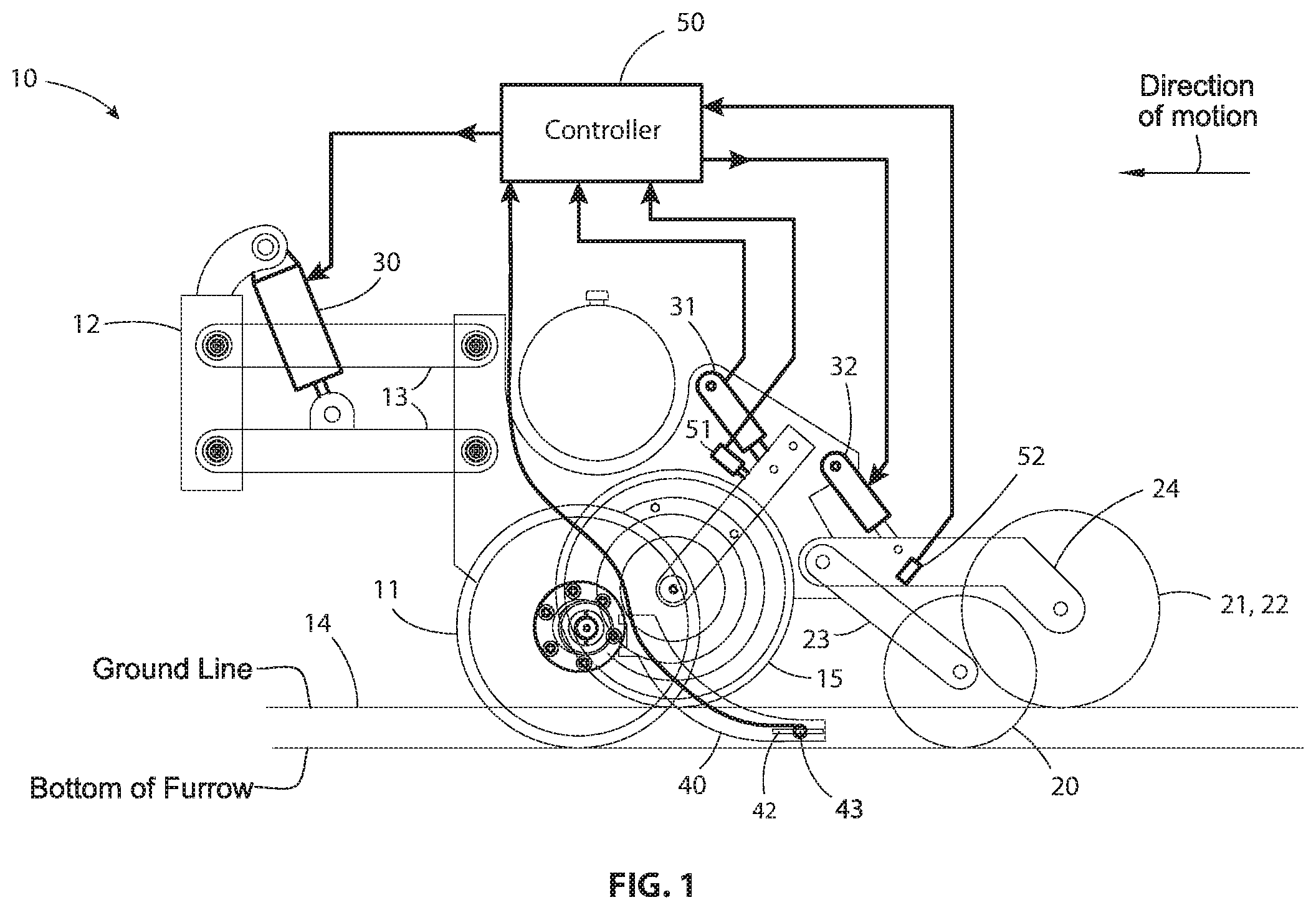
FIG. 1 is a side elevation, partially schematic, of a planter row unit that includes multiple control systems.
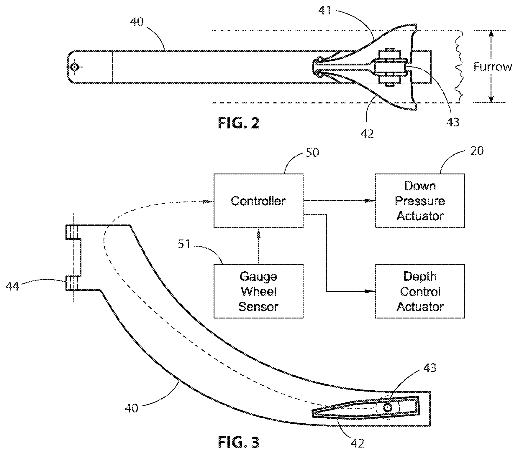
FIG. 2 is an enlarged plan view of the sidewall compaction measuring device in the row unit of FIG. 1.
FIG. 3 is a side elevation of the sidewall compaction measuring device shown in FIG. 2.
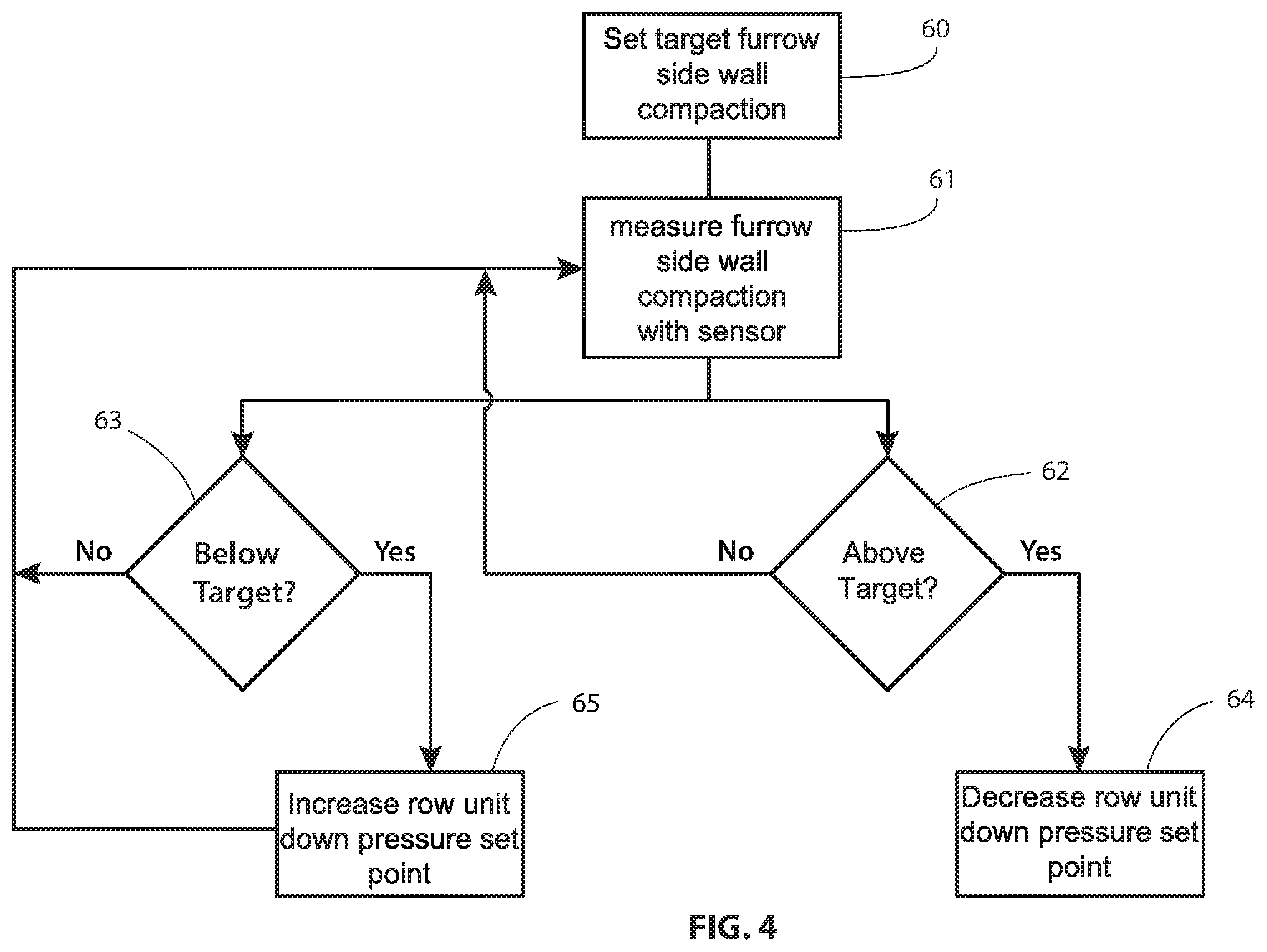
FIG. 4 is a flow chart of an algorithm executed by the controller shown in FIGS. 1 and 3, using the output signal from the sidewall compaction measuring device.
DETAILED DESCRIPTION OF ILLUSTRATED EMBODIMENTS
Although the invention will be described in connection with certain preferred embodiments, it will be understood that the invention is not limited to those particular embodiments. On the contrary, the invention is intended to cover all alternatives, modifications and equivalent arrangements as may be included within the spirit and scope of invention as defined by the appended claims.
In the embodiment illustrated in FIG. 1, a planting row unit 10 includes a furrow-opening device 11 for the purpose of planting seed or injecting fertilizer into the soil. A conventional elongated hollow towing frame 12 (typically hitched to a tractor by a draw bar) is rigidly attached to the front frame of a conventional four-bar linkage assembly 13 that is part of the row unit 10. The four-bar (sometimes referred to as "parallel-bar") linkage assembly 13 is a conventional and well known linkage used in agricultural implements to permit the raising and lowering of tools attached thereto.
As the planting row unit 10 is advanced by a tractor, the opening device 11 penetrates the soil to form a furrow or seed slot 14 having a depth D. A gauge wheel 15 determines the planting depth for the seed and the height of introduction of fertilizer, etc. The planting row unit 10 is urged downwardly against the soil by its own weight and, in addition, a hydraulic cylinder 30 is coupled between the front frame 12 and the linkage assembly 13 to urge the row unit 10 downwardly with a controllable force that can be adjusted for different soil conditions. The hydraulic cylinder 30 may also be used to lift the row unit off the ground for transport by a heavier, stronger, fixed-height frame that is also used to transport large quantities of fertilizer for application via multiple row units.
A system for controlling the down pressure applied to the row unit by the hydraulic cylinder 14 is described in U.S. Pat. No. 9,226,440, issued Jan. 5, 2016.
Bins on the row unit carry the chemicals and seed which are directed into the soil. Other portions of the row unit 10 then deposit seed in the seed slot and fertilizer adjacent to the seed slot, and the seeds are pressed into the bottom of the furrow by a firming wheel 20. The furrow is closed by a pair of closing wheels 21 and 22 that are pressed into opposite side walls of the furrow 14 to distribute loosened soil into the furrow, over the seeds in the bottom of the furrow. The firming wheel is carried on the end of an arm 23, and the closing wheels 21, 22 are carried on the end of an arm 24. The arms 23 and 24 are mounted for pivoting movement about a common axis 25, and a hydraulic cylinder 32 presses the closing wheels downwardly with a controlled pressure.
In accordance with one embodiment of the present invention, a narrow bar 40 trails the opening device 10 in the furrow 14 to monitor the hardness or compaction of the soil that forms the side walls of the furrow. The monitoring device 40 has two hard metal wings 41 and 42 that protrude laterally from the sides of the bar 40. The distance between the tips of the wings 41 and 42 is slightly longer than the width of the furrow opened by the opening device 11. The force exerted on the wings 41 and 42 by the soil in the furrow sidewalls is transmitted to a load cell 43 (or other force-measuring device), producing an electrical signal that is proportional to the strain on the wings. That strain varies with the hardness or level of compaction of the soil in the furrow sidewalls.
In the embodiment illustrated in FIGS. 2 and 3, the bar 40 has a yoke 44 at the upper end for attachment to the frame of the row unit. The bar 40 curves downwardly into the furrow 14 so that the trailing end of the bar slides on the bottom of the furrow, as depicted in FIG. 1. The wings 41 and 42 are mounted on the bar 40 near its trailing end, on opposite sides of a load cell 43. The distance between the outer ends of the wings 41 and 42 is smaller than the width of the furrow 14, so that the tips of the wings penetrate into the sidewalls of the furrow. The resulting forces applied to the wing tips urge the wings toward each other, thereby applying opposed forces to opposite ends of the load cell 43 located between the two wings 41 and 42. This causes the load cell 43 to produce an electrical output signal having a magnitude proportional to the forces applied to the wings, which in turn is proportional to the hardness or compaction of the soil in the side walls of the furrow.
The signal from the load cell 43 is supplied to a controller 50 that also receives input signals from sensors 51 and 52 on the support arms 53 and 24 that carry the gauge wheel 15 and the closing wheels 21, 22. The controller 50 uses these three input signals to produce three output signals that control three hydraulic cylinders 20, 31 and 32 that apply down forces to (a) the four-bar linkage for the entire row unit, (b) the arm that carries the gauge wheel 15, and (c) the closing wheels 21, 22, respectively.
The algorithm used by the controller 20 to control the down force applied to the gauge wheel 15 compares the signal received from the load cell 43 with a target value for the sidewall compaction. One example of such an algorithm is depicted by the flow chart in FIG. 4. The first step 60 sets a target value for furrow side wall compaction. Then the actual furrow side wall compaction is measured and compared with the target value at step 61. Step 62 determines whether the measured value is more than a predetermined value above the target value, and if the answer is affirmative, the row unit down pressure set point is decreased at step 64 by sending a signal to the controller 50. Step 63 determines whether the measured value is more than a predetermined value below the target value, and if the answer is affirmative, the row unit down pressure set point is increased at step 65 by sending a signal to the controller 50. A negative answer at either step 62 or 63 returns the system to step 61.
To increase or decrease the row unit down pressure set point, the controller 50 produces an output signal that adjusts the set point of the row unit gauge wheel down force control system. For example, if the set point of down force control system is set at 200 lbs and the algorithm produces a signal to increase that set point, the down force control system increase the set point to 225 lbs. This added force on the gauge wheel increases the compression of the soil under the gauge wheel, adjacent the vee opener. If the signal from the force-measuring device is still too low, the controller 50 will receive a signal from the algorithm to increase the set point again. This process is repeated until the signal from the sidewall compaction-measuring device falls within a dead band around the set point of the row unit gauge wheel down force control system. If the signal from the compaction-measuring device is too high, the controller 50 produces an output signal that decreases the set point rather than increasing it. The control system thus prevents over-compaction of the furrow, thereby allowing optimal root growth. It also solves the operator's problem of how to set an automatic down pressure control system.
The winged device can serve multiple purposes at the same time. For example, it can act as a seed firmer by locating the bar 40 downstream of where seed is deposited in the furrow. In another example, the wings 41 and 42 can be provided with passageways that permit liquid or gas fertilizer to pass through the blades and into the grooves cut in the side of the furrow by the wings 41 and 42.
While particular embodiments and applications of the present invention have been illustrated and described, it is to be understood that the invention is not limited to the precise construction and compositions disclosed herein and that various modifications, changes, and variations can be apparent from the foregoing descriptions without departing from the spirit and scope of the invention as defined in the appended claims.
* * * * *
References
D00000
D00001
D00002
D00003
XML
uspto.report is an independent third-party trademark research tool that is not affiliated, endorsed, or sponsored by the United States Patent and Trademark Office (USPTO) or any other governmental organization. The information provided by uspto.report is based on publicly available data at the time of writing and is intended for informational purposes only.
While we strive to provide accurate and up-to-date information, we do not guarantee the accuracy, completeness, reliability, or suitability of the information displayed on this site. The use of this site is at your own risk. Any reliance you place on such information is therefore strictly at your own risk.
All official trademark data, including owner information, should be verified by visiting the official USPTO website at www.uspto.gov. This site is not intended to replace professional legal advice and should not be used as a substitute for consulting with a legal professional who is knowledgeable about trademark law.