Sound collection equipment and method for detecting the operation status of the sound collection equipment
Liao , et al. Ja
U.S. patent number 10,547,940 [Application Number 16/167,597] was granted by the patent office on 2020-01-28 for sound collection equipment and method for detecting the operation status of the sound collection equipment. This patent grant is currently assigned to UNLIMITER MFA CO., LTD.. The grantee listed for this patent is Unlimiter MFA Co., Ltd.. Invention is credited to Kuan-Li Chao, Jian-Ying Li, Ho-Hsin Liao, Po-Jui Wu, Kuo-Ping Yang, Neo Bob Chih-Yung Young.


| United States Patent | 10,547,940 |
| Liao , et al. | January 28, 2020 |
Sound collection equipment and method for detecting the operation status of the sound collection equipment
Abstract
A sound collection equipment is disclosed. The sound collection equipment includes a speaker, a microphone and a processing unit. The speaker is used for generating a test sound having a first frequency. The microphone is used for receiving an external sound. The processing unit is electronically connected to the microphone and the processing unit. The processing unit is used for determining whether a frequency range of the external sound includes the first frequency and whether the energy of the external sound exceeds a predetermined energy value, and for judging that the sound collection equipment is in a usage state when the frequency range of the external sound includes the first frequency and the energy of the external sound does not exceed the predetermined energy value.
| Inventors: | Liao; Ho-Hsin (Taipei, TW), Chao; Kuan-Li (Taipei, TW), Young; Neo Bob Chih-Yung (Taipei, TW), Yang; Kuo-Ping (Taipei, TW), Li; Jian-Ying (Taipei, TW), Wu; Po-Jui (Taipei, TW) | ||||||||||
|---|---|---|---|---|---|---|---|---|---|---|---|
| Applicant: |
|
||||||||||
| Assignee: | UNLIMITER MFA CO., LTD. (Eden
Island, SC) |
||||||||||
| Family ID: | 69180032 | ||||||||||
| Appl. No.: | 16/167,597 | ||||||||||
| Filed: | October 23, 2018 |
| Current U.S. Class: | 1/1 |
| Current CPC Class: | H04R 29/004 (20130101); H04R 3/02 (20130101); H04R 3/04 (20130101); H04R 2225/021 (20130101); H04R 25/453 (20130101); H04R 2430/01 (20130101); H04R 25/558 (20130101); H04R 25/30 (20130101) |
| Current International Class: | H04R 3/04 (20060101); H04R 29/00 (20060101); H04R 25/00 (20060101) |
References Cited [Referenced By]
U.S. Patent Documents
| 9843872 | December 2017 | Liao |
| 2004/0196992 | October 2004 | Ryan |
| 2004/0202333 | October 2004 | Csermak |
| 2005/0058300 | March 2005 | Suzuki |
| 2005/0221792 | October 2005 | Mattisson |
| 2006/0251265 | November 2006 | Asada |
| 2009/0012297 | January 2009 | Pagoria |
| 2009/0304195 | December 2009 | Fillol |
| 2015/0086028 | March 2015 | Gaiser |
| 2015/0139430 | May 2015 | Miyata |
| 2017/0034642 | February 2017 | Takahashi |
| 2017/0070815 | March 2017 | Mitsufuji |
| 201142111 | Oct 2008 | CN | |||
| 103303404 | Sep 2013 | CN | |||
| 2004297368 | Oct 2004 | JP | |||
| 2006304244 | Nov 2006 | JP | |||
| 2016116001 | Jun 2016 | JP | |||
Assistant Examiner: Ganmavo; Kuassi A
Attorney, Agent or Firm: Bacon & Thomas, PLLC
Claims
What is claimed is:
1. A sound collection equipment, comprising: a speaker, used for generating a test sound having a first frequency, wherein the first frequency is X Hz; a microphone, used for receiving an external sound; and a processor unit, electrically connected to the speaker and the microphone, comprising: a frequency detection module, used for determining if a frequency range of the external sound include the first frequency and a second frequency band which is Y Hz, where X-1000<Y<X; a volume detection module, used for determining if the energy of the external sound exceeds a predetermined energy value; and control module, used for judging that the sound collection equipment is in a usage state when the frequency range of the external sound includes the first frequency but does not include the second frequency band and the energy of the external sound does not exceed the predetermined energy value.
2. The sound collection equipment of claim 1, wherein the frequency detection module is further used for determining if the frequency range of the external sound includes a third frequency which is Z Hz, where X<Z<X+1000; the control module is used for judging that the sound collection equipment is in a usage state when the frequency range of the external sound includes the first frequency but does not include the second frequency band and the third frequency and the energy of the external sound does not exceed the predetermined energy value.
3. The sound collection equipment of claim 1, wherein 8000<X<40,000.
4. The sound collection equipment of claim 1, further comprising a sound amplifier, the sound amplifier being electrically connected to the processor unit; when the frequency range of the external sound includes the first frequency and the energy of the external sound exceeds the predetermined energy value, the control module is further used for controlling the sound amplifier to stop amplifying sounds received by the microphone or to reduce an amplification level of the sounds received by the microphone.
5. The sound collection equipment of claim 1, wherein the sound collection equipment being in the usage state refers to the speaker being at or exceeding a predetermined distance from the microphone.
6. The sound collection equipment of claim 1, wherein the sound collection equipment being in the usage state refers to an object being located between the speaker and the microphone.
7. The method, for detecting an operating state of a sound collection equipment, applicable to a sound collection equipment, which comprises a speaker and a microphone, the method comprising the following steps: generating a test sound having a first frequency via the speaker, wherein the first frequency is X Hz; receiving an external sound via the microphone; determining if the frequency range of the external sound includes the first frequency and a second frequency band which is Y Hz, where X-1000<Y<X; determining if the energy of the external sound exceeds a predetermined energy value; whereby with the above steps, if the frequency range of the external sound includes the first frequency but does not include the second frequency band and the energy of the external sound does not exceed the predetermined energy value, the sound collection equipment is judged to be in a usage state.
8. The method of claim 7, further comprising the following step: determining if the frequency range of the external sound includes a third frequency which is Z Hz, where X<Z<X+1000; whereby with the above steps, if the frequency range of the external sound includes the first frequency but does not include the second frequency band and the third frequency and the energy of the external sound does not exceed the predetermined energy value, the sound collection equipment is judged to be in a usage state.
9. The method of claim 7, wherein 8000<X<40,000.
10. The method of claim 7, wherein the sound collection equipment further comprises a sound amplifier; when the frequency range of the external sound includes the first frequency and the energy of the external sound exceeds the predetermined energy value, the method further comprises the following step: controlling the sound amplifier to stop amplifying the sound received by the microphone or to reduce an amplification level of the sound received by the microphone.
11. The method of claim 7, wherein the sound collection equipment being in the usage state refers to the speaker being at or exceeding a predetermined distance from the microphone.
12. The method of claim 7, wherein the sound collection equipment being in the usage state refers to an object being located between the speaker and the microphone.
Description
BACKGROUND OF THE INVENTION
1. Field of the Invention
The present invention relates to a sound collection equipment and a method for detecting an operation status of a sound collection equipment, in particular to a sound collection equipment having both a speaker and a microphone and the method for detecting an operation status of a sound collection equipment.
2. Description of the Related Art
Typically, when a user uses a sound collection equipment such as a hearing aid, the speaker generates annoying high frequency sounds when the microphone is too close to the speaker. This phenomenon, referred to as audio feedback, generally occurs unintentionally when the microphone and the speaker are in close proximity to each other during operation, and the high frequency sound can startle users and generate unpleasant user experiences.
U.S. Pat. No. 9,843,872 discloses a method for detecting an operating state of a sound collection equipment, which can determine whether the sound collection equipment is in the usage state according to the energy of a test sound generated by a speaker and received by a microphone, and which controls a sound amplifier of the sound collection equipment to stop amplifying sound received by the microphone when the sound collection equipment is in the usage state. However, sound received by the microphone may arrive from any environmental source, so the sound received by the microphone may not be the test sound generated by the speaker, such that there may be some error in the determination of the method.
Therefore, it is desirable to provide a method to reduce or eliminate the audio feedback phenomenon in order to resolve the abovementioned issue.
SUMMARY OF THE INVENTION
The objective of the present invention is to provide a sound collection equipment and a method to detect the operating state of the sound collection equipment.
In order to achieve the above objective, the sound collection equipment of the present invention comprises a speaker, a microphone and a processor unit. The speaker is used for generating a test sound having a first frequency. The microphone is used for receiving an external sound. The processor unit is electrically connected to the speaker and the microphone. The processor unit comprises a frequency detection module, a volume detection module and a control module. The frequency detection module is used for determining if a frequency range of the external sound includes the first frequency. The volume detection module is used for determining if the energy of the external sound exceeds a predetermined energy value. The control module is used for judging that the sound collection equipment is in a usage state when the frequency range of the external sound includes the first frequency and the energy of the external sound does not exceed the predetermined energy value.
The method for detecting the operating state of a sound collection equipment of the present invention can be applied to a sound collection equipment which comprises a speaker and a microphone. The method for detecting the operating state of a sound collection equipment of the present invention includes the following steps: generating a test sound having a first frequency via the speaker; receiving an external sound via the microphone; determining if a frequency range of the external sound includes the first frequency; and determining if the energy of the external sound exceeds a predetermined energy value. With the above steps, if the frequency range of the external sound includes the first frequency and the energy of the external sound does not exceed the predetermined energy value, the sound collection equipment is judged to be in a usage state.
BRIEF DESCRIPTION OF THE DRAWINGS
These and other objects and advantages of the present invention will become apparent from the following descriptions of the accompanying drawings, which disclose several embodiments of the present invention. It is to be understood that the drawings are to be used for purposes of illustration only, and not as a definition of the invention.
In the drawings, wherein similar reference numerals denote similar elements throughout the several views:
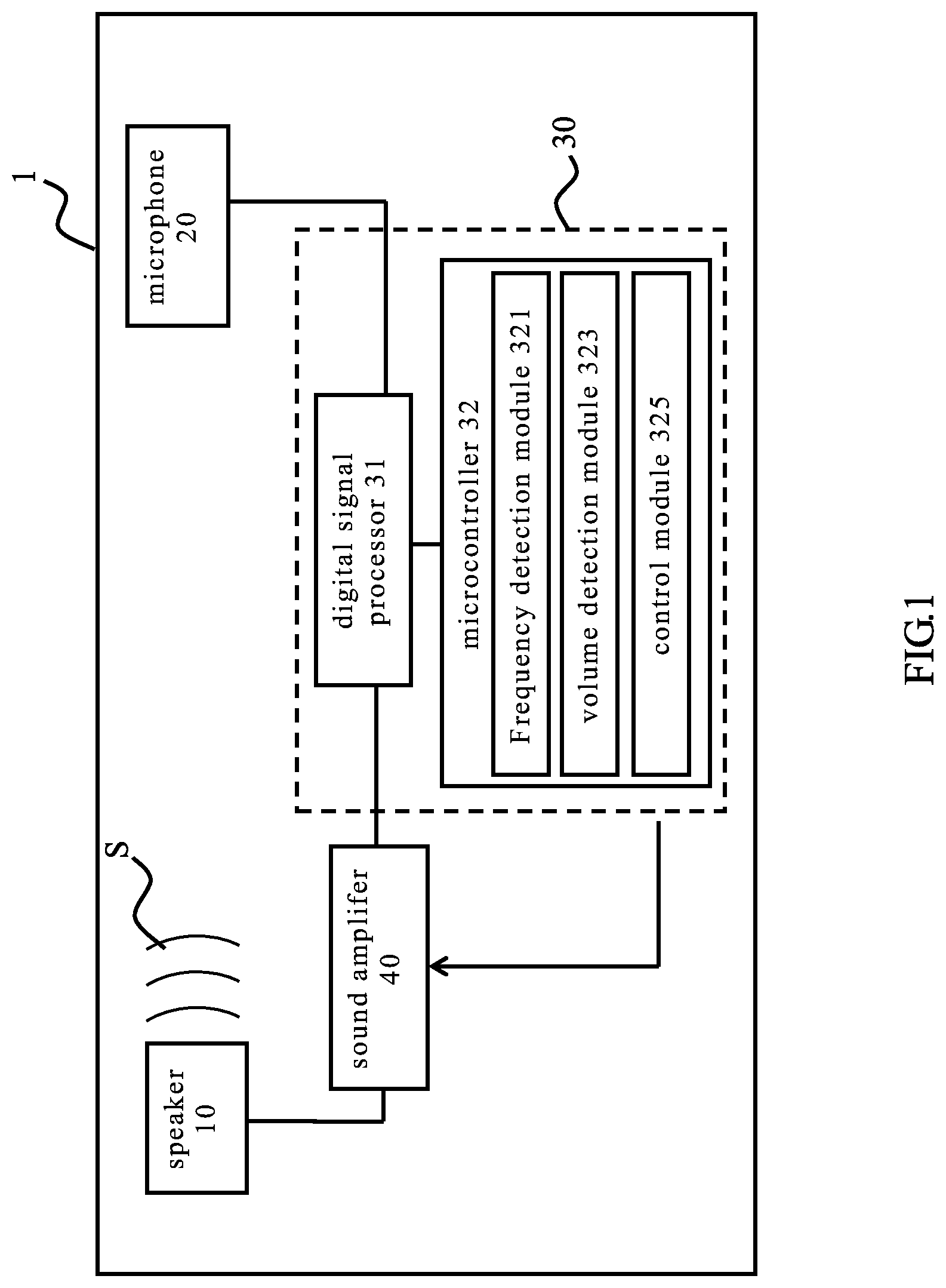
FIG. 1 is a device architecture diagram of the sound collection equipment of the present invention;
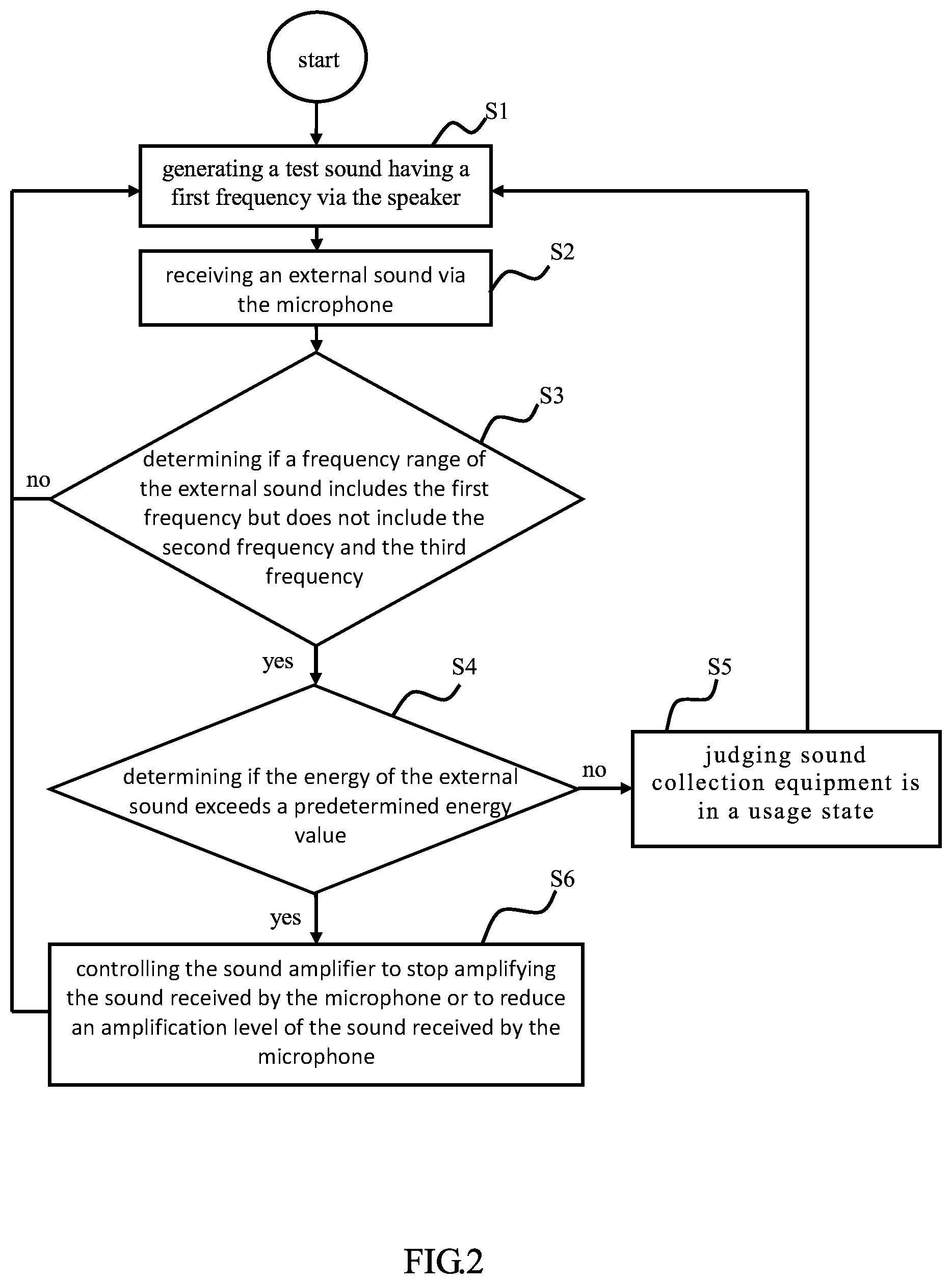
FIG. 2 is a step flowchart of a method for detecting an operating state of a sound collection equipment of the present invention;
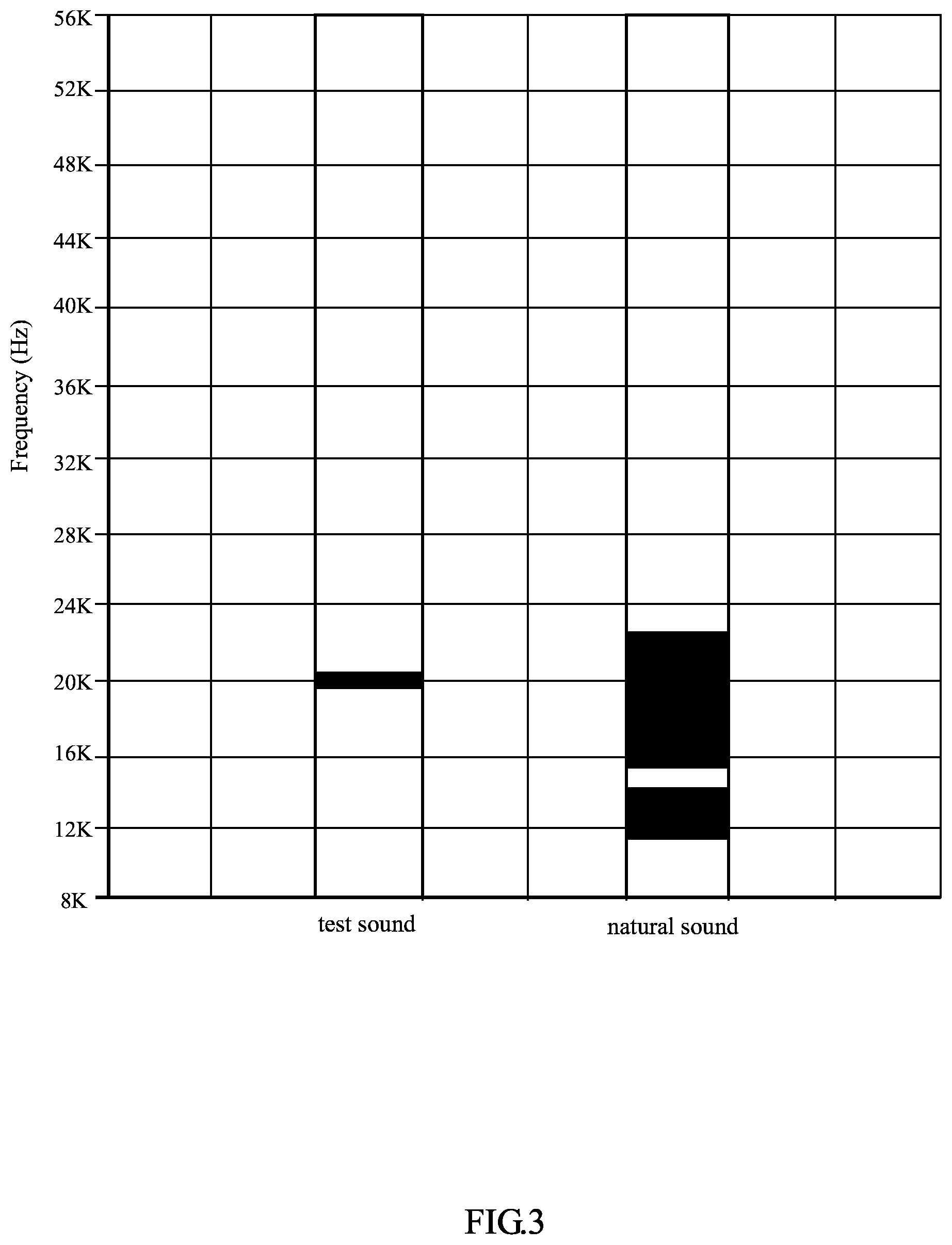
FIG. 3 shows the distribution of the frequency range of a test sound and an environmental sound.
FIG. 4 is a schematic diagram of the first embodiment indicating that the electronic device is in a usage state;
FIG. 5 is a schematic diagram of the first embodiment indicating that the electronic device is not in a usage state;
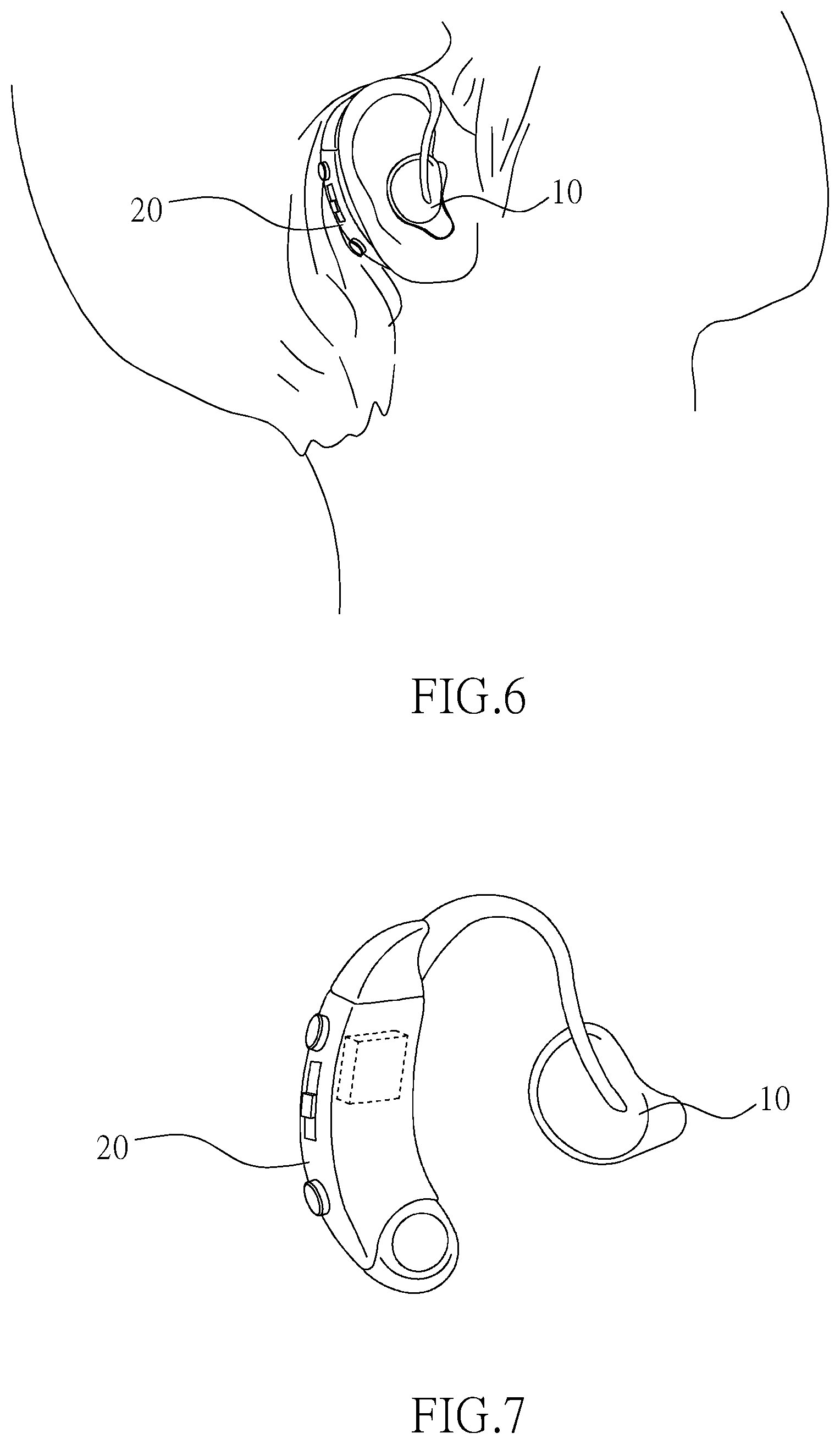
FIG. 6 is a schematic diagram of the second embodiment indicating that the electronic device is in a usage state; and
FIG. 7 is a schematic diagram of the second embodiment indicating that the electronic device is not in a usage state.
DETAILED DESCRIPTION OF THE PREFERRED EMBODIMENT
The following embodiments are provided in order to further explain the implementations of the present invention. It should be noted that the objects used in the diagrams of the embodiments are provided with proportions, dimensions, deformations, displacements and details as examples and that the present invention is not limited thereto; identical components in the embodiments are the given same component numbers.
First, refer to FIG. 1, which is a device architecture diagram of the sound collection equipment of the present invention
As shown in FIG. 1, in an embodiment of the present invention, a sound collection equipment 1 of the present invention comprises a speaker 10, a microphone 20, a processor unit 30 and a sound amplifier 40. In a specific embodiment of the present invention, the sound collection equipment 1 is a hearing aid, but the scope of the present invention is not limited thereto.
In an embodiment of the present invention, the speaker 10 is used for generating a test sound S which has a first frequency, wherein the first frequency is X Hz, where 8,000.ltoreq.X.ltoreq.40,000. Preferably, the first frequency of the test sound S is about 20,000 Hz and the loudness of the test sound S does not exceed 20 dB, but the scope of the present invention is not limited thereto.
In an embodiment of the present invention, the microphone 20 is used for receiving an external sound, which may be a test sound S generated by the speaker 10 or be other sounds from the environment. After the microphone 20 receives the external sound, the microphone 20 can generate an input sound signal according to the external sound, and the input sound signal is transmitted to the processor unit 30 for processing.
In an embodiment of the present invention, the processor unit 30 is electrically connected to the speaker 10 and the microphone 20. The processor unit 30 comprises a digital signal processor 31 and a micro controller 32. The digital signal processor 31 is used for processing the input sound signal transmitted from the microphone 20 to generate a corresponding output sound signal. The output sound signal is transmitted to the sound amplifier 40.
In an embodiment of the present invention, the micro controller 32 of the processor unit 30 comprises a frequency detection module 321, a volume detection module 323 and a control module 325. It should be noted that the above respective modules may not only be configured as hardware devices, software programs, firmware, or combinations thereof, but configured by circuit loop or other suitable types. Also, each of the modules can be configured individually or in combination. A preferred embodiment is that all of the modules are configured as software programs, which are installed into a memory (not shown in figures) of the micro controller 32 and implemented by a processor (not shown in figures) of the micro controller 32 to achieve their functions. Additionally, the preferred embodiment of the present invention described herein is only illustrative. To avoid redundancy, not all the possible combinations of changes are documented in detail. However, it shall be understood by those skilled in the art that each of the modules or elements described above may not be necessary. For the implementation of the present invention, the present invention may also contain other detailed, conventional modules or elements. Each module or component is likely to be omitted or modified depending on various demands. Other modules or elements may not necessarily exist between any two modules.
In an embodiment of the present invention, the frequency detection module 321 is used for determining if a frequency range of the external sound received by the microphone 20 includes the first frequency but does not include a second frequency and a third frequency, wherein the second frequency is Y Hz, where X-1000<Y<X, and the third frequency is Z Hz, where X<Z<X+1000. In other embodiments of the present invention, the frequency detection module 321 can only determine if a frequency range of the external sound received by the microphone 20 includes the first frequency. In other words, it is not necessary to determine if the frequency range of the external sound does not include a second frequency and a third frequency.
In an embodiment of the present invention, the volume detection module 323 is signally connected to the frequency detection module 321. The volume detection module 323 is used for determining if the energy of the external sound received by the microphone 20 exceeds a predetermined energy value.
In an embodiment of the present invention, the control module 325 is signally connected with the frequency detection module 321 and the volume detection module 323. The control module 325 is used for judging that the sound collection equipment 1 is in a usage state when the frequency range of the external sound received by the microphone 20 includes the first frequency but does not include the second frequency and the third frequency and the energy of the external sound does not exceed the predetermined energy value. The usage state of the sound collection equipment 1 and determination of the frequency and volume will be described in detail below, so they are not explained here.
In an embodiment of the present invention, the sound amplifier 40 is electrically connected to the processor unit 30. The sound amplifier 40 is used for amplifying an output sound signal generated by the digital signal processor 31 of the processor unit 30 and transferring the amplified output sound signal to the speaker 10 such that the speaker 10 plays sounds according to the amplified output sound signal.
Next, refer to FIG. 1 to FIG. 7. FIG. 2 is a step flowchart of a method for detecting an operating state of a sound collection device according to the present invention. The steps shown in FIG. 2 are further presented in detail in FIG. 1 and in FIG. 3 to FIG. 7. It should be noted that the following implementation is based on the sound collection equipment 1 described previously to illustrate the method for detecting an operating state of a sound collection equipment according to the present invention. However, the scope of the method for detecting an operating state of a sound collection equipment according to the present invention is not limited to the sound collection equipment 1 described previously.
First, executing step S1: generating a test sound having a first frequency via the speaker.
The method for detecting an operating state of a sound collection equipment of the present invention is applicable to a sound collection equipment 1, such that as shown in FIG. 1, and the sound collection equipment 1 includes a speaker 10 and a microphone 20. In the first step of the method, the micro controller 32 of the processor unit 30 controls the speaker 10 to generate a test sound S having a first frequency (i.e., the micro controller 32 generates and transmits an output sound signal to the speaker 10). In a specific embodiment of the present invention, the first frequency is X Hz, where 8000.ltoreq.X.ltoreq.40,000. The frequency range of the test sound S approximates a single frequency, which is preferably about 20,000 Hz, as shown in FIG. 3 (i.e., X is substantially 20,000).
Executing step S2: receiving an external sound via the microphone.
The microphone 20 of the sound collection equipment 1 can receive an external sound which may be a test sound S generated by the speaker 10 or other sounds from the environment.
Executing step S3: determining if a frequency range of the external sound includes the first frequency but does not include the second frequency and the third frequency.
Because the microphone 20 can receive any sounds from the environment, in a specific embodiment of the present invention, the frequency detection module 321 of the processor unit 30 not only determines if the frequency range of the external sound includes the first frequency but also further determines if the frequency range of the external sound does not include a second frequency and a third frequency to confirm that the external sound received by the microphone 20 is the test sound S to avoid misjudgment. The values of the second frequency and the third frequency are close to that of the first frequency, wherein the second frequency is Y Hz, where X-1000<Y<X, and the third frequency is Z Hz, where X<Z<X+1000. For example, assume that the first frequency is 20,000 Hz as described above; the second frequency is 19,001-19,999 Hz and the third frequency is 20,001-20,999 Hz.
As shown in FIG. 3, the frequency range of sound generated from the environment is broad, which means that the frequency range of the environmental sound covers a wide range. However, the frequency range of the test sound S is approximate to a single frequency, so the control module 325 can judge that the external sound is the test sound S when the frequency detection module 321 further determines that the frequency range of the external sound does not include the second frequency and the third frequency. If the frequency range of the external sound does not include the first frequency or includes the second frequency and the third frequency, step S4 is not executed.
Executing step S4: determining if the energy of the external sound exceeds a predetermined energy value.
In an embodiment of the present invention, after step S3 is executed, if the frequency range of the external sound received by the microphone 20 includes the first frequency but does not include the second frequency and the third frequency, i.e., it is determined that the external sound is the test sound S, the volume detection module 323 will determine if the energy of the external sound exceeds a predetermined energy value (for example: 10 dB).
As shown in FIG. 1 and FIG. 4, in an embodiment of the present invention, when a user uses the sound collection equipment 1, i.e., the sound collection equipment 1 is in a usage state, the speaker 10 of the sound collection equipment 1 is placed near the ears of the user, and the microphone 20 hangs on the user's chest. Accordingly, the distance between the speaker 10 and the microphone 20 is equal to or greater than a certain distance. As shown in FIG. 5, when the user does not use the sound collection equipment 1 and wants to store the sound collection equipment 1, the microphone 20 frequently is placed at less than the certain distance from the speaker 10 in order to reduce the required storage space. Therefore, the sound collection equipment 1 being in the usage state refers to the speaker 10 being at a predetermined distance (for example: 60 cm or more) from the microphone 20. Because the sound collection equipment 1 is in the usage state, the distance between the speaker 10 and microphone 20 is equal to or greater than the predetermined distance. Thus, the energy of the test sound S received by the microphone 20 does not exceed the predetermined energy value. On the other hand, when the sound collection equipment 1 is not in the usage state, the distance between the speaker 10 and the microphone 20 is shorter than the predetermined distance. Thus, the energy of the test sound S received by the microphone 20 exceeds the predetermined energy value. As a result, if the external sound received by microphone 20 is definitely the test sound S and the energy of the external sound does not exceed the predetermined energy value, it is judged that the sound collection equipment 1 is in a usage state (step S5). In contrast, if the external sound is definitely the test sound S and the energy of the external sound exceeds the predetermined energy value, it is judged that the sound collection equipment 1 is not in the usage state.
As shown in FIG. 1 and FIG. 6, in another embodiment of the present invention, when a user uses the sound collection equipment 1, i.e., the sound collection equipment 1 is in the usage state, the speaker 10 of the sound collection equipment 1 is placed near the ears and the microphone 20 is placed at the back of the ear. The speaker 10 and the microphone 20 are blocked by the auricle. On the other hand, as shown in FIG. 7, once the user removes the sound collection equipment 1 from the ear, the speaker 10 and the microphone 20 are not blocked by any objects. Accordingly, in this embodiment, the sound collection equipment 1 being in the usage state refers to an object being located between the speaker and the microphone of the sound collection equipment 1. When the sound collection equipment 1 is in the usage state, the speaker 10 and the microphone 20 of the sound collection equipment 1 are blocked by an object, and the energy value of the test sound S received by the microphone 20 does not exceed a predetermined energy value. On the other hand, when the sound collection equipment 1 is not in the usage state, the speaker 10 and the microphone 20 of the sound collection equipment 1 are not blocked by an object, and the energy value of the test sound S received by the microphone 20 exceeds a predetermined energy value. As a result, if the external sound received by the microphone 20 is definitely the test sound S and the energy of the external sound does not exceed the predetermined energy value, it is judged that the sound collection equipment 1 is in a usage state (step S5). In contrast, if the external sound is definitely the test sound S and the energy of the external sound exceeds the predetermined energy value, it is judged that the sound collection equipment 1 is not in the usage state.
Execute step S6: controlling the sound amplifier to stop amplifying the sound received by the microphone or to reduce an amplification level of the sound received by the microphone.
Once it is determined that the sound collection equipment 1 is not in the usage state, i.e., the frequency range of the external sound includes the first frequency but does not include the second frequency and the third frequency and the energy of the external sound exceeds the predetermined energy value, the control module 325 of the micro controller 32 of the processor unit 30 controls the sound amplifier 40 to stop amplifying the sound received by the microphone 20 or to reduce an amplification level of the sound received by the microphone 20 in order to prevent the audio feedback resulting from the speaker 10 and the microphone 20 being placed too close to each other.
According to the above description, the method for detecting an operating state of a sound collection equipment of the present invention is to judge if the sound collection equipment 1 is in the usage state by determining the energy level of the test sound S and to stop amplifying the sound received by the microphone or to reduce an amplification level of the sound received by the microphone so as to prevent audio feedback from occurring when the sound collection equipment 1 is not in the usage state. Furthermore, the method for detecting an operating state of a sound collection equipment of the present invention is to make sure that the sound received by the microphone 20 is definitely the test sound S from the speaker 10 in order to prevent misjudgment of the source of the sound.
While the present invention has been particularly shown and described with reference to a preferred embodiment, it will be understood by those skilled in the art that various changes and modifications can be made to the described embodiments. It is intended to include all such variations, modifications and equivalents which fall within the scope of the invention, as defined in the accompanying claims. It is to be understood that many other possible modifications and variations can be made without departing from the spirit and scope of the invention as hereinafter claimed.
* * * * *
D00000
D00001
D00002
D00003
D00004
D00005
XML
uspto.report is an independent third-party trademark research tool that is not affiliated, endorsed, or sponsored by the United States Patent and Trademark Office (USPTO) or any other governmental organization. The information provided by uspto.report is based on publicly available data at the time of writing and is intended for informational purposes only.
While we strive to provide accurate and up-to-date information, we do not guarantee the accuracy, completeness, reliability, or suitability of the information displayed on this site. The use of this site is at your own risk. Any reliance you place on such information is therefore strictly at your own risk.
All official trademark data, including owner information, should be verified by visiting the official USPTO website at www.uspto.gov. This site is not intended to replace professional legal advice and should not be used as a substitute for consulting with a legal professional who is knowledgeable about trademark law.