Zoom lens and camera device
Iwasawa , et al. Ja
U.S. patent number 10,545,321 [Application Number 15/364,590] was granted by the patent office on 2020-01-28 for zoom lens and camera device. This patent grant is currently assigned to TAMRON CO., LTD.. The grantee listed for this patent is TAMRON CO., LTD.. Invention is credited to Yoshito Iwasawa, Jun Takahashi.


View All Diagrams
| United States Patent | 10,545,321 |
| Iwasawa , et al. | January 28, 2020 |
Zoom lens and camera device
Abstract
A zoom lens has in order from the object side, at least a foremost, first lens group having positive refractive power, a succeeding, second lens group having negative refractive power, a third lens group having positive refractive power, and a rearmost lens group having negative refractive power. The zoom lens meets requirements as defined in formulas regarding a displacement of the first lens group, a focal length of the zoom lens at the wide-angle end, a focal length of the zoom lens at the telephoto end, a focal length of the first lens group, and a focal length of the third lens group.
| Inventors: | Iwasawa; Yoshito (Tokyo, JP), Takahashi; Jun (Ashigarakami-gun, JP) | ||||||||||
|---|---|---|---|---|---|---|---|---|---|---|---|
| Applicant: |
|
||||||||||
| Assignee: | TAMRON CO., LTD. (Saitama-shi,
JP) |
||||||||||
| Family ID: | 50993025 | ||||||||||
| Appl. No.: | 15/364,590 | ||||||||||
| Filed: | November 30, 2016 |
Prior Publication Data
| Document Identifier | Publication Date | |
|---|---|---|
| US 20170082841 A1 | Mar 23, 2017 | |
Related U.S. Patent Documents
| Application Number | Filing Date | Patent Number | Issue Date | ||
|---|---|---|---|---|---|
| 14141011 | Dec 26, 2013 | ||||
Foreign Application Priority Data
| Dec 27, 2012 [JP] | 2012-286012 | |||
| Current U.S. Class: | 1/1 |
| Current CPC Class: | G02B 5/005 (20130101); G02B 27/0025 (20130101); G02B 15/173 (20130101); G02B 27/646 (20130101) |
| Current International Class: | G02B 15/173 (20060101); G02B 5/00 (20060101); G02B 27/00 (20060101); G02B 27/64 (20060101) |
| Field of Search: | ;359/554,557,676,683,689,690,763,764,771,772,773,784-788 ;348/208.99 ;396/52,55 |
References Cited [Referenced By]
U.S. Patent Documents
| 4478496 | October 1984 | Kato |
| 6025962 | February 2000 | Suzuki |
| 6618197 | September 2003 | Hayakawa |
| 7433584 | October 2008 | Masui et al. |
| 7535654 | May 2009 | Ohashi |
| 7630138 | December 2009 | On |
| 7630141 | December 2009 | Saruwatari |
| 7995284 | August 2011 | Matsui |
| 8982477 | March 2015 | Wada |
| 9140905 | September 2015 | Misaka |
| 2005/0219708 | October 2005 | Shibayama et al. |
| 2006/0221464 | October 2006 | Shibayama et al. |
| 2007/0058268 | March 2007 | Terada |
| 2007/0229974 | October 2007 | Shibayama et al. |
| 2008/0285150 | November 2008 | Souma |
| 2009/0284847 | November 2009 | Ishibashi |
| 2010/0220400 | September 2010 | Yamamoto et al. |
| 2010/0271710 | October 2010 | Ohashi |
| 2011/0102905 | May 2011 | Harada |
| 2011/0116174 | May 2011 | Suzuki et al. |
| 2011/0176224 | July 2011 | Sato |
| 2011/0188117 | August 2011 | Arakawa et al. |
| 2012/0026602 | February 2012 | Uchida et al. |
| 2012/0057234 | April 2012 | Li |
| 2012/0293872 | November 2012 | Katayose et al. |
| 102103253 | Jun 2011 | CN | |||
| 102798965 | Nov 2012 | CN | |||
| 1975668 | Oct 2008 | EP | |||
| 2005-284097 | Oct 2005 | JP | |||
| 2008-26837 | Feb 2008 | JP | |||
| 2010-019945 | Jan 2010 | JP | |||
| 2010-175899 | Aug 2010 | JP | |||
| 2011-099925 | May 2011 | JP | |||
| 2011-158630 | Aug 2011 | JP | |||
| 2011-248220 | Dec 2011 | JP | |||
| 2012-053444 | Mar 2012 | JP | |||
| 2012-208434 | Oct 2012 | JP | |||
| 10-2012-0070491 | Jun 2012 | KR | |||
Other References
|
Non-Final Office Action dated Mar. 7, 2017, issued in U.S. Appl. No. 15/364,588 (17 pages). cited by applicant . Final Office Action dated Mar. 24, 2017, issued in U.S. Appl. No. 14/414,011 (21 pages). cited by applicant . Office Action dated Oct. 24, 2016, issued in counterpart Japanese Patent Application No. 2012-286012. (8 pages). cited by applicant . Chinese Office Action dated Dec. 21, 2015, issued in counterpart Chinese Patent Application No. 201310726394.4. (5 pages). cited by applicant . Notice of Allowance dated May 18, 2018, issued in U.S. Appl. No. 15/364,588 (8 pages). cited by applicant. |
Primary Examiner: Allen; Stephone B
Assistant Examiner: Booher; Adam W
Attorney, Agent or Firm: Westerman, Hattori, Daniels & Adrian, LLP
Parent Case Text
CROSS-REFERENCE TO RELATED APPLICATIONS
The present patent application is a continuation of application Ser. No. 14/141,011, filed Dec. 26, 2013, which claims priority from Japanese Application No. 2012-286012, filed Dec. 27, 2012, which are incorporated herein by reference in their entireties.
Claims
We claim:
1. A zoom lens comprising at least three groups of lens pieces comprising in order from the object side a first lens group having refractive power, a second lens group having refractive power, and a third lens group having refractive power and movable to vary magnification, and wherein one of: a lens block is included in the third lens group, the lens block included in the third lens group having at least one lens piece and negative refractive power and being movable in directions normal to the optical axis to serve as an anti-vibration lens for shifting an image; one lens group is included behind the third lens group, the one lens group behind the third lens group having negative refractive power and being movable in directions normal to the optical axis to serve as an anti-vibration lens for shifting an image; and a lens block is included in a lens group behind the third lens group, the lens block included in a lens group behind the third lens group having at least one lens piece and negative refractive power and being movable in directions normal to the optical axis to serve as an anti-vibration lens for shifting an image; and wherein the zoom lens meets the following formulae: 0.11.ltoreq.X1/fT.ltoreq.0.28 (1) 0.20.ltoreq.f3/ {square root over ((fw.times.fT))}.ltoreq.0.3005 (3) 0.60.ltoreq.Lt/fT.ltoreq.0.75 (5) where X1 is a displacement of the first lens group when the zoom lens is extended from a wide-angle end to a telephoto end to vary magnification, fw is a focal length of the zoom lens at the wide-angle end, fT is a focal length of the zoom lens at the telephoto end, f3 is a focal length of the third lens group, and Lt is an entire length of the optical system of the zoom lens at the telephoto end.
2. The zoom lens according to claim 1, wherein the zoom lens comprises at least one of: at least one lens block or group of positive refractive power located adjacent to the object via a space and closer to the object than all or part of the lens group or lens block of negative refractive power moved to serve as an anti-vibration lens for shifting an image and at least one component lens piece of positive refractive power located adjacent to the object via a space closer to the object than all or part of the lens group or lens block of negative refractive power moved to serve as an anti-vibration lens for shifting an image.
3. The zoom lens according to claim 1, wherein at least one lens group having a negative refractive power behind the second lens group has one or more lens pieces of positive and negative refractive power.
4. The zoom lens according to claim 1, wherein part or all of the lens group(s) moved to serve as an anti-vibration lens for shifting an image meet the requirements as defined in the following formula (4): -2.8.ltoreq.(1-.beta.a).times..beta.b.ltoreq.-1.0 (4) where .beta.a is a magnification of the lens group(s) movable in directions normal to the optical axis when the zoom lens is taking a posture of the telephoto end, and .beta.b is a combined magnification of a lens group(s) closer to the imaging plane than the lens group(s) movable in directions normal to the optical axis.
5. The zoom lens according to claim 1, wherein the zoom lens has two or more lens groups located behind the third lens group and moved to vary magnification.
6. A camera device comprising image sensors disposed on or behind the imaging plane of the zoom lenses according to claim 1, for converting an optical image created by the zoom lens into electrical signals.
7. A zoom lens comprising in order from the object side at least a foremost, first lens group having refractive power, a succeeding second lens group having refractive power, a third lens group having refractive power, a fourth lens group having refractive power, and a fifth lens group having refractive power, wherein the distances between the first and second lens groups, between the second and third lens groups, between the third and fourth lens groups, and between the fourth and fifth lens groups change when zooming, and wherein one of: a lens block is included in one of the third lens group, the fourth lens group, and the fifth lens group, the lens block having at least one lens piece and negative refractive power and being movable in directions normal to the optical axis to serve as an anti-vibration lens for shifting an image; the fourth lens group has negative refractive power and is movable in directions normal to the optical axis to serve as an anti-vibration lens for shifting an image; and the fifth lens group has negative refractive power and is movable in directions normal to the optical axis to serve as an anti-vibration lens for shifting an image; wherein a lens piece located closer to the object than all or part of the anti-vibration lens is adjacent to the anti-vibration lens and has negative power; and wherein the zoom lens meets the requirements as defined in the following formulae: 0.11.ltoreq.X1/fT.ltoreq.0.28 (1) 0.20.ltoreq.f3/ {square root over ((fw.times.fT))}.ltoreq.0.3005 (3) 0.60.ltoreq.Lt/fT.ltoreq.0.75 (5) where X1 is a displacement of the first lens group when the zoom lens is extended from the wide-angle end to the telephoto end to vary magnification, fw is a focal length of the zoom lens at the wide-angle end, fT is a focal length of the zoom lens at the telephoto end, f3 is a focal length of the third lens group, and Lt is an entire length of the optical system of the zoom lens at the telephoto end.
8. The zoom lens according to claim 7, wherein the zoom lens comprises at least one of: at least one lens group of positive refractive power and at least one component lens piece of positive refractive power located closer to the object than at least part of at least one of the lens groups of negative refractive power moved to serve as an anti-vibration lens for shifting an image.
9. The zoom lens according to claim 7, wherein the zoom lens has one or more lens pieces of positive and negative refractive power in at least part of at least one of the lens groups of negative refractive power moved to serve as an anti-vibration lens for shifting an image.
10. The zoom lens according to claim 7, wherein part or all of the lens group(s) moved to serve as an anti-vibration lens for shifting an image meet the requirements as defined in the following formula (4): -2.8.ltoreq.(1-.beta.a).times..beta.b.ltoreq.-1.0 (4) where .beta.a is a magnification of the lens group(s) movable in directions normal to the optical axis when the zoom lens is taking a posture of the telephoto end, and .beta.b is a combined magnification of a lens group(s) closer to the imaging plane than the lens group(s) movable in directions normal to the optical axis.
11. The zoom lens according to claim 7, wherein the zoom lens has two or more lens groups located behind the third lens group and moved to vary magnification.
12. A camera device comprising image sensors disposed on or behind the imaging plane of the zoom lenses according to claim 7, for converting an optical image created by the zoom lens into electrical signals.
Description
FIELD OF THE INVENTION
The present invention relates to zoom lenses, interchangeable lens units incorporating the zoom lenses, and camera devices used with the same. More particularly, the present invention relates to high variable power compact zoom lenses suitable to camera optical systems for digitized signal input/output devices such as digital still cameras, digital video cameras, and the like, interchangeable lens units incorporating the zoom lenses, and camera devices used with the same.
BACKGROUND ART
Recently, camera devices, such as digital still cameras, incorporating solid-state image sensors have been popular. This tendency of the market demand has been followed by the performance improvement and downsizing of optical systems, and more compact camera systems have rapidly become commercially available. Optical systems in such camera systems are of higher-performance oriented and increasingly downsizing oriented design to meet the market demands for zoom lens optical systems with a shortened entire length and for lens barrels with a reduced diameter. Especially, it is highly desired that optical systems, such as tele-photographing zoom lenses, having an increased focal length should be of more enhanced performance and reduced dimensions.
One prior art highly variable power compact zoom lens, which satisfies the demands of higher-performance and reduced dimensions, comprises the foremost or first lens group G1 of positive refractive power located the closest to an object, the succeeding or second lens group G2 of negative refractive power, the third lens group G3 of positive refractive power, and the fourth lens group L4 of positive refractive power located the closest to the imaging plane, and such a prior art zoom lens meets the requirements as defined in the following formula: 12<Lt/(Ft/Fw)<15 where Lt is an entire length of the optical system (a distance from the front surface of the front lens piece the closest to the object to the imaging plane) when the zoom lens is taking a telephoto position, Ft is a focal length of the optical system as a whole when the zoom lens is taking a telephoto position, and Fw is a focal length of the optical system as a whole when the zoom lens is taking a wide-angle position (e.g., see Patent Document 1 listed below).
LIST OF DOCUMENTS OF THE RELATED ART
Patent Document 1
Official Gazette of JP-A-2011-248220
The prior art highly variable power compact zoom lens mentioned above has its lens group of negative refractive power deviated/displaced in directions normal to the optical axis to serve as an anti-vibration lens, which is intended to downsize the lens barrel by downsizing the anti-vibration lens in a diametral dimension. Due to a great displacement of the first lens group, however, the cam mechanism in the lens barrel is unavoidably so complicated as recognized in multi-stage cam design, and the resultant zoom lens is still unsatisfactory in that the lens barrel is not sufficiently downsized.
Allowing for the aforementioned disadvantages in the prior art highly variable power compact zoom lens, the present invention is directed to providing an improved zoom lens that attains high-performance imaging suitable to changeable lenses and/or camera devices incorporating solid-state image sensors, such as digital still cameras, digital video cameras, and the like, of which pixels are much more minute than those of photographing film, and providing an improved camera device used with such a zoom lens.
The present invention is also directed to providing an improved zoom lens in which a displacement of a lens group(s) moved to vary magnification is reduced so as to reduce a diametral dimension of the lens barrel and simplify a barrel structure, and also, in which a lens group(s) of negative refractive power serve as an anti-vibration lens to attain the same object, namely to reduce the diametral dimension of the lens barrel.
SUMMARY OF THE INVENTION
A first zoom lens in accordance with the present invention comprises three or more groups of lens pieces, the foremost or first lens group of positive refractive power located the closest to an object, the succeeding second lens group of negative refractive power, and the third lens group of positive refractive power, all arranged in this order, and if any, the rearmost lens group(s) closer to the imaging plane than the third lens group, all or part of the lens group(s) of negative refractive power behind the third lens group being moved in directions normal to the optical axis to serve as an anti-vibration lens for shifting an image; and the zoom lens meets the requirements as defined in the following formula: 0.11.ltoreq.X1/fT.ltoreq.0.28 (1) 0.5.ltoreq.f1/ {square root over ((fw.times.fT))}.ltoreq.1.3 (2) 0.20.ltoreq.f3/ {square root over ((fw.times.fT))}.ltoreq.0.45 (3) where X1 is a displacement of the first lens group when the zoom lens is extended from the wide-angle position to the telephoto position to vary magnification, fw is a focal length of the zoom lens at the wide-angle position, fT is a focal length of the zoom lens at the telephoto position, f1 is a focal length of the first lens group, and f3 is a focal length of the third lens group.
A second zoom lens in accordance with the present invention comprises five or more groups of lens pieces, the foremost or first lens group of positive refractive power located the closest to an object, the succeeding second lens group of negative refractive power, the third lens group of positive refractive power, the fourth lens group, and the fifth lens group, all arranged in this order, all or part of the lens group(s) of negative refractive power behind the third lens group being moved in directions normal to the optical axis to serve as an anti-vibration lens for shifting an image; and the zoom lens meets the requirements as defined in the following formula: 0.11.ltoreq.X1/fT.ltoreq.0.28 (1) 0.5.ltoreq.f1/ {square root over ((fw.times.fT))}.ltoreq.1.3 (2) where X1 is a displacement of the first lens group when the zoom lens is extended from the wide-angle position to the telephoto position to vary magnification, fw is a focal length of the zoom lens at the wide-angle position, fT is a focal length of the zoom lens at the telephoto position, and f1 is a focal length of the first lens group.
A camera device in accordance with the present invention comprises image sensors disposed on or behind the imaging plane of any of the aforementioned zoom lenses according to the present invention, for converting an optical image created by the zoom lens into electrical signals.
In accordance with the present invention, the zoom lens attains high-performance imaging suitable to attachment lenses and/or camera devices incorporating solid-state image sensors, such as digital still cameras, digital video cameras, and the like, of which pixels are much more minute than those of photographing film, and the camera device is suitably used with such a zoom lens.
Moreover, in the zoom lens according to the present invention, a displacement of a lens group(s) moved to vary magnification is reduced so as to reduce a diametral dimension of the lens barrel and simplify a barrel structure, and also, the lens group(s) of negative refractive power serve as an anti-vibration lens to attain the same object, namely to reduce the diametral dimension of the lens barrel.
Furthermore, the zoom lens according to the present invention, which comprises at least three groups of lens pieces, namely, the foremost or first lens group of positive refractive power positioned the closest to an object, the second lens group of negative refractive power, and the third lens group of positive refractive power, and if any, the rearmost lens group(s) behind the third lens group, is capable of varying three or more dimensional components or distances between the lens groups adjacent to each other during varying its magnification so as to obtain an enhanced freedom to compensate for aberrations.
In a first aspect of the present invention, the first zoom lens meets the requirements as defined about the third lens group in the following formula (3): 0.20.ltoreq.f3/ {square root over ((fw.times.fT))}.ltoreq.0.45 (3) where f3 is a focal length of the third lens group.
In a second aspect of the present invention, the first or second zoom lens of the present invention comprises a lens group(s) of positive refractive power and/or a component lens piece(s) of positive refractive power located closer to the object than all or part of the lens group(s) of negative refractive power moved to serve as an anti-vibration lens for shifting an image.
In a third aspect of the present invention, the first or second zoom lens of the present invention has one or more lens pieces of positive and negative refractive power in all or part of the lens group(s) of negative refractive power moved to serve as an anti-vibration lens for shifting an image.
In a fourth aspect of the present invention, the first or second zoom lens of the present invention is designed so that part or all of the lens group(s) moved to serve as an anti-vibration lens for shifting an image meet the requirements as defined in the following formula (4): -2.8.ltoreq.(1-.beta.a).times..beta.b.ltoreq.-1.0 (4) where .beta.a is a magnification of the lens group(s) movable in directions normal to the optical axis when the zoom lens is taking a telephoto position, and .beta.b is a combined magnification of a lens group(s) closer to the imaging plane than the lens group(s) movable in directions normal to the optical axis.
In a fifth aspect of the present invention, the first or second zoom lens of the present invention is designed to meet the requirements as defined in the following formula (5): 0.60.ltoreq.Lt/fT.ltoreq.0.75 (5) where Lt is an entire length of the optical system of the zoom lens at the telephoto position, and fT is a focal length of the zoom lens at the telephoto position.
In a sixth aspect of the present invention, the first or second zoom lens of the present invention comprises two or more lens groups located behind the third lens group and moved to vary magnification.
The formula (1) defines the requirements for a displacement of the first lens group in the zoom lens during extending from the wide-angle position to the telephoto position.
When an actual value of X1/fT exceeds the upper limit defined in the formula (1), the displacement of the first lens group in the resultant zoom lens is increased, and this unavoidably brings about a complicated barrel design as recognized in a multi-stage lens barrel arrangement, which in turn hinders downsizing the lens barrel.
When an actual value of X1/fT is smaller than the lower limit defined in the formula (1), the resultant zoom lens has its optical system varied not so much in entire length between the telephoto position and the wide-angle position, but the entire length of the optical system at the wide-angle position is excessively great, which in turn brings about an increase in a diameter of the first lens group located the closest to the object as well as an increase of an entire longitudinal dimension of the lens barrel.
To obtain more significant effects, the formula (1) may desirably be modified as follows: 0.11.ltoreq.X1/fT.ltoreq.0.22 (1')
To obtain much more significant effects, the formula (1) may desirably be modified as follows: 0.11.ltoreq.X1/fT.ltoreq.0.18 (1'')
The formula (2) defines the requirements for a focal distance of the first lens group in the zoom lens.
When an actual value of f1/ (fwfT) is smaller than the lower limit defined in the formula (2) to intensify the positive refractive power of the first lens group, the resultant zoom lens taking a telephoto position develops chromatic aberration so great as to cause a difficulty in compensating for it.
When an actual value of f1/ (fwfT) exceeds the upper limit defined in the formula (1) to weaken the positive refractive power of the first lens group, a light beam incident upon the second lens group is not sufficiently converged, and this unavoidably brings about an increase in dimensions of the second lens group and an increase in a displacement of the first lens group, which in turn leads to an increase in dimensions of the lens barrel as a whole.
To obtain more significant effects, the formula (2) may desirably be modified as follows: 0.6.ltoreq.f1/ {square root over ((fw.times.fT).ltoreq.1.2)} (2')
To obtain much more significant effects, the formula (2) may desirably be modified as follows: 0.7.ltoreq.f1/ {square root over ((fw.times.fT).ltoreq.1.1)} (2'')
The formula (3) defines the requirements for a focal distance of the third lens group in the zoom lens.
When an actual value of f3/ (fwfT) is smaller than the lower limit defined in the formula (3) to intensify the positive refractive power of the first lens group, the resultant zoom lens taking a telephoto position develops spherical aberration so great as to cause a difficulty in compensating for it.
When an actual value of f3/ (fwfT) exceeds the upper limit defined in the formula (3) to weaken the positive refractive power of the first lens group, a light beam incident upon the lens group(s) or an anti-vibration lens behind the third lens group is not sufficiently converged, and this unavoidably brings about an increase in dimensions of the anti-vibration lens and an increase in dimensions of an anti-vibration lens unit, which in turn leads to an increase in dimensions of the lens barrel as a whole.
To obtain more significant effects, the formula (3) may desirably be modified as follows: 0.20.ltoreq.f3/ {square root over ((fw.times.fT))}.ltoreq.0.40 (3')
To obtain much more significant effects, the formula (3) may desirably be modified as follows: 0.20.ltoreq.f3/ {square root over ((fw.times.fT))}.ltoreq.0.35 (3'')
The formula (4) defines the requirements for a rate of a displacement of the lens group(s) movable in directions normal to the optical axis to an amount by which an image is shifted.
When an actual value of (1-.beta.a).beta.b is smaller than the lower limit defined in the formula (4), the resultant zoom lens adversely permits an image to shift greatly even with a minor displacement of the lens group(s) movable in directions normal to the optical axis or the anti-vibration lens, and thus, high-precision control of the anti-vibration lens is required.
When an actual value of (1-.beta.a).beta.b exceeds the upper limit defined in the formula (4), the resultant zoom lens has to have the anti-vibration lens displaced more in directions normal to the optical axis to shift the image by a predetermined amount, and for that purpose, a larger lens actuator system for driving the anti-vibration lens is needed, which hinders downsizing the lens barrel.
The formula (5) defines the requirements for dimensions of the optical system of the zoom lens at the telephoto position.
Fulfilling the conditions defined in the formula (5) enables the zoom lens especially to have the optical system considerably reduced in entire length when it is taking a telephoto position and have the optical system enhanced in imaging performance.
When an actual value of Lt/fT is smaller than the lower limit defined in the formula (5), the resultant zoom lens has its optical system excessively reduced in entire length when it is taking a telephoto position, and the zoom lens encounters a difficulty in ensuring the desired optical performance when it is taking a wide-angle position.
Reversely, when an actual value of Lt/fT exceeds the upper limit defined in the formula (5), the resultant zoom lens has its optical system increased in entire length when it is taking a telephoto position, which hinders downsizing the lens barrel.
BRIEF DESCRIPTION OF THE DRAWINGS
FIG. 1 is a vertical sectional view showing a lens arrangement in a first embodiment of a zoom lens according to the present invention when the zoom lens is taking a wide-angle position,
FIG. 2 depicts graphs of spherical aberration, astigmatism, and distortion aberration developed in the first embodiment of the zoom lens when the zoom lens taking a wide-angle position is in focus at a point at infinity, the graphs of spherical aberration showing a ratio of a stop setting F-number to the full diaphragm stop setting F-number on the vertical axis and a degree of defocusing on the horizontal axis for the d-line (wavelength 587.6 nm) expressed by solid line, the c-line (wavelength 656.3 nm) by broken line, and the g-line (wavelength 435.8 nm) by alternate long and short dash line, the graphs of astigmatism showing an image height on the vertical axis and a degree of defocusing on the horizontal axis for a sagittal imaging plane expressed by solid line and a meridional imaging plane by broken line, and the graphs of distortion aberration show an image height on the vertical axis and a degree of distortion in percentage,
FIG. 3 depicts graphs of spherical aberration, astigmatism, and distortion aberration developed in the first embodiment of the zoom lens when the zoom lens taking an intermediate zooming state is in focus at a point at infinity,
FIG. 4 depicts graphs of spherical aberration, astigmatism, and distortion aberration developed in the first embodiment of the zoom lens when the zoom lens taking a telephoto position is in focus at a point at infinity,
FIG. 5 is a vertical sectional view showing a lens arrangement in a second embodiment of the zoom lens according to the present invention when the zoom lens is taking a wide-angle position,
FIG. 6 depicts graphs of spherical aberration, astigmatism, and distortion aberration developed in the second embodiment of the zoom lens when the zoom lens taking a wide-angle position is in focus at a point at infinity,
FIG. 7 depicts graphs of spherical aberration, astigmatism, and distortion aberration developed in the second embodiment of the zoom lens when the zoom lens taking an intermediate zooming state is in focus at a point at infinity,
FIG. 8 depicts graphs of spherical aberration, astigmatism, and distortion aberration developed in the second embodiment of the zoom lens when the zoom lens taking a telephoto position is in focus at a point at infinity,
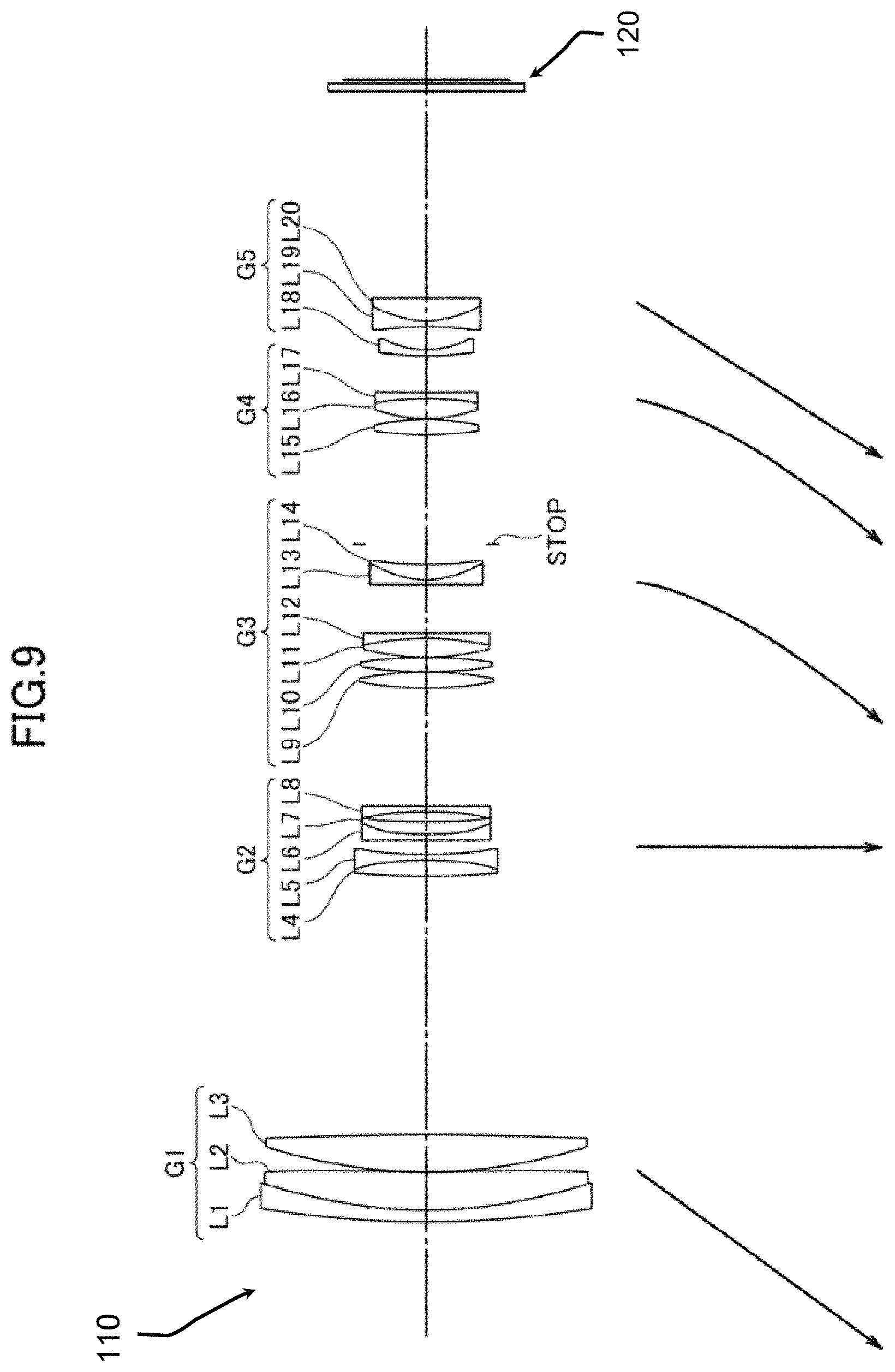
FIG. 9 is a vertical sectional view showing a third embodiment of the zoom lens according to the present invention when the zoom lens is taking a wide-angle position,
FIG. 10 depicts graphs of spherical aberration, astigmatism, and distortion aberration developed in the third embodiment of the zoom lens when the zoom lens taking a wide-angle position is in focus at a point at infinity,
FIG. 11 depicts graphs of spherical aberration, astigmatism, and distortion aberration developed in the third embodiment of the zoom lens when the zoom lens taking an intermediate zooming state is in focus at a point at infinity,
FIG. 12 depicts graphs of spherical aberration, astigmatism, and distortion aberration developed in the third embodiment of the zoom lens when the zoom lens taking a telephoto position is in focus at a point at infinity,
FIG. 13 is a vertical sectional view showing a fourth embodiment of the zoom lens according to the present invention when the zoom lens is taking a wide-angle position,
FIG. 14 depicts graphs of spherical aberration, astigmatism, and distortion aberration developed in the fourth embodiment of the zoom lens when the zoom lens taking a wide-angle position is in focus at a point at infinity,
FIG. 15 depicts graphs of spherical aberration, astigmatism, and distortion aberration developed in the fourth embodiment of the zoom lens when the zoom lens taking an intermediate zooming state is in focus at a point at infinity,
FIG. 16 depicts graphs of spherical aberration, astigmatism, and distortion aberration developed in the fourth embodiment of the zoom lens when the zoom lens taking a telephoto position is in focus at a point at infinity,
FIG. 17 is a vertical sectional view showing a fifth embodiment of the zoom lens according to the present invention when the zoom lens is taking a wide-angle position,
FIG. 18 depicts graphs of spherical aberration, astigmatism, and distortion aberration developed in the fifth embodiment of the zoom lens when the zoom lens taking a wide-angle position is in focus at a point at infinity,
FIG. 19 depicts graphs of spherical aberration, astigmatism, and distortion aberration developed in the fifth embodiment of the zoom lens when the zoom lens taking a position in the intermediate zooming state is in focus at a point at infinity, and
FIG. 20 depicts graphs of spherical aberration, astigmatism, and distortion aberration developed in the fifth embodiment of the zoom lens when the zoom lens taking a telephoto position is in focus at a point at infinity.
FIG. 21 is a diagrammatic representation of a camera incorporating a zoom lens in accordance with the present invention and image sensors.
BEST MODE OF THE INVENTION
As shown in FIG. 21, a camera device 100 in accordance with the present invention comprises a zoom lens 110 and image sensors 120 disposed on or behind the imaging plane of the zoom lens, for converting an optical image created by the zoom lens into electrical signals.
Embodiment 1
FIG. 1 is a vertical sectional view showing a lens arrangement of a first embodiment of a zoom lens according to the present invention. The first embodiment of the zoom lens comprises the foremost or first lens group G1 of positive refractive power located the closest to an object, the succeeding second lens group G2 of negative refractive power, the third lens group G3 of positive refractive power, the fourth lens group G4 of positive refractive power, the fifth lens group G5 of negative refractive power, and the rearmost or sixth lens group G6 of negative refractive power arranged in this order.
The first lens group G1 comprises a duplet of a meniscus lens piece L1 of negative refractive power with its convex surface oriented to the object and a lens piece L2 of positive refractive power cemented with the meniscus lens piece L1, and a lens piece L3 of positive refractive power, all the lens pieces being arranged in this order from the closest to the object in the foremost position to the farthest in the rearmost position.
The second lens group G2 comprises a duplet of a lens piece L4 of negative refractive power with its concave surface oriented toward the object and a meniscus lens piece L5 of positive refractive power cemented with the lens piece L4, and a meniscus lens piece L6 of negative refractive power with its concave surface oriented toward the object.
The third lens group G3 comprises a biconvex lens piece L7, a biconvex lens piece L8, a duplet of a lens piece L9 of positive refractive power with its convex surface oriented toward the object and a lens piece L10 of negative refractive power cemented with the lens piece L9, and another duplet of a biconcave lens piece L11 and a meniscus lens piece L12 of positive refractive power with its convex surface oriented toward the object, all the lens pieces arranged in this order from the closest to the object in the foremost position to the farthest in the rearmost position.
The fourth lens group G4 comprises a biconvex lens piece L13, and a duplet of a lens piece L14 of positive refractive power with its convex surface oriented toward the object and a lens piece L15 of positive refractive power cemented with the lens piece L14, all the lens pieces being arranged in this order from the closest to the object in the foremost position to the farthest from the object in the rearmost position.
The fifth lens group G5 comprises a duplet of a biconvex lens piece L16 positioned closer to the object and a biconcave lens piece L17 cemented with the biconvex lens piece L16.
The sixth lens group G6 comprises a meniscus lens piece L18 of negative refractive power with its concave surface oriented toward the object.
During varying magnification from the wide-angle and to the telephoto position, the first embodiment of the zoom lens has its first lens group moved toward the object, its second lens group held in a fixed position, its third lens group moved on a trajectory that draws an arc toward the imaging plane relative to the second lens group, its fourth lens group moved on a trajectory that draws an arc toward the imaging plane relative to the third lens group, its fifth lens group moved toward the object, and its sixth lens group moved in the same manner as the fourth lens group.
Focusing on an object at the near point is carried out by moving the fifth lens group toward the imaging plane. For that purpose, the duplet of the lens pieces L11 and L12 cemented together is moved in vertical directions normal to the optical axis so as to correct fuzziness of an image during photographing.
Optical data of the lens pieces in the first embodiment of the zoom lens are provided in Table 1. Surface number NS designates the n-th lens surface of the optical system where all the component lens pieces are arranged in order on the closest-to-the-object-first basis, R is a radius of curvature of the n-th lens surface, D is a distance along the optical axis between a pair of the adjacent lens surfaces, Nd is a refractive index for the d-line (wavelength .lamda.=587.6 nm), and vd is an Abbe number for the d-line (wavelength .lamda.=587.6 nm).
An aperture stop or an aperture diaphragm is denoted by STOP suffixed to the surface number.
TABLE-US-00001 TABLE 1 NS R D Nd .nu.d 1 486.4782 1.4500 1.83400 37.34 2 83.3399 0.0100 1.56732 42.84 3 83.3399 5.5100 1.49700 81.61 4 -172.8214 0.1500 5 63.2093 5.2914 1.48749 70.44 6 -895.6302 D(6) 7 0.0000 1.8876 8 -96.2544 0.7500 1.76524 50.37 9 18.4045 0.0100 1.56732 42.84 10 18.4045 3.0631 1.80518 25.46 11 70.9807 2.5194 12 -41.5515 0.7000 1.80420 46.50 13 -10114.4818 D(13) 14 39.2470 4.1119 1.49700 81.61 15 -41.3613 0.1000 16 40.1380 2.6375 1.48749 70.44 17 -1692.6300 0.1000 18 43.0535 3.8276 1.48749 70.44 19 -29.6342 0.0100 1.56732 42.84 20 -29.6342 0.7000 1.90739 33.25 21 119.5406 6.7000 22 -1390.5046 0.6000 1.77791 44.07 23 18.4637 0.0100 1.56732 42.84 24 18.4637 2.3536 1.90366 31.31 25 48.8224 2.3000 26 STOP 0.0000 D(26) 27 52.7369 2.8298 1.56732 42.84 28 -27.8361 0.1000 29 26.5392 3.2246 1.54356 46.62 30 -23.1396 0.0100 1.56732 42.84 31 -23.1396 0.6000 1.90366 31.31 32 104.0723 D(32) 33 54.2263 1.4342 1.80518 25.46 34 -61.6536 0.0100 1.56732 42.84 35 -61.6536 0.5600 1.74161 49.80 36 16.9498 D(36) 37 -24.4610 0.9300 1.48749 70.44 38 -87.3035 0.0000 39 0.0000 D(39) 40 0.0000 2.8000 1.51680 64.20 41 0.0000 1.0000
Distances between the adjacent lens surfaces in several pairs in the first embodiment of the zoom lens are given in Table 2 below as well as varied values of the focal distance f, the F-number Fno, and the field angle .omega. for each of the zooming settings at the wide-angle position (f=68.7634), at the intermediate zooming state (f=149.5669), and at the telephoto position (f=291.2580), respectively.
TABLE-US-00002 TABLE 2 f 68.7634 149.5669 291.2580 Fno 4.62776 5.18280 6.80830 .omega. 6.8004 3.13810 1.61270 D(6) 18.4552 49.5086 57.3552 D(13) 24.5140 18.2970 1.5000 D(26) 4.3452 4.2773 7.7592 D(32) 5.4806 1.4000 2.7630 D(36) 11.0774 15.1581 13.7950 D(39) 19.7269 26.0118 39.3269
Distances between the adjacent lens surfaces in several pairs in the first embodiment of the zoom lens during focusing on an object at the near point for zooming settings at the wide-angle position (f=68.7634), at the intermediate zooming state (f=149.5669), and at the telephoto position (f=291.2580), respectively, are given in Table 3 below as well as varied values of the focal length f upon focusing on an object at infinite distance away and the distance D(0) from the front surface of the first lens piece to the object.
TABLE-US-00003 TABLE 3 f 68.7634 149.5669 291.2580 D(0) 1058.11 1027.06 1019.21 D(32) 6.6285 4.8033 12.0080 D(36) 9.9260 11.7548 4.5501
Embodiment 2
FIG. 5 is a vertical sectional view showing a lens arrangement of a second embodiment of the zoom lens according to the present invention. The second embodiment of the zoom lens comprises the foremost or first lens group G1 of positive refractive power located the closest to an object, the succeeding second lens group G2 of negative refractive power, the third lens group G3 of positive refractive power, the fourth lens group G4 of positive refractive power, and the fifth lens group G5 of negative refractive power, all the lens groups being arranged in this order.
The first lens group G1 comprises a duplet of a meniscus lens piece L1 of negative refractive power with its convex surface oriented to the object and a lens piece L2 of positive refractive power cemented with the meniscus lens piece L1, and a meniscus lens piece L3 of positive refractive power with its convex surface oriented to the object, all the lens pieces being arranged in this order from the closest to the object in the foremost position to the farthest in the rearmost position.
The second lens group G2 comprises a duplet of a lens piece L4 of positive refractive power and a lens piece L5 of negative refractive power cemented with the lens piece L4, another duplet of a lens piece L6 of positive refractive power with its convex surface oriented toward the object and a lens piece L7 of negative refractive power cemented with the lens piece L6, and a meniscus lens piece L8 of negative refractive power with its concave surface oriented to the object, all the lens pieces being arranged in this order from the closest to the object in the foremost position to the farthest in the rearmost position.
The third lens group G3 comprises a biconvex lens piece L9, a biconvex lens piece L10, a duplet of a lens piece L11 of positive refractive power with its convex surface oriented to the object and a lens piece L12 of negative refractive power cemented with the lens piece L11, and another duplet of a biconcave lens piece L13 and a meniscus lens piece L14 of positive refractive power with its convex surface oriented to the object, and cemented with the biconcave lens piece L13, all the lens pieces being arranged in this order from the closest to the object in the foremost position to the farthest in the rearmost position.
The fourth lens group G4 comprises a biconvex lens piece L15, and a duplet of a lens piece L16 of positive refractive power with its convex surface oriented toward the object and a lens piece L17 of negative refractive power cemented with the lens piece L16, all the lens pieces being arranged in this order from the closest to the object in the foremost position to the farthest from the object in the rearmost position.
The fifth lens group G5 comprises a lens piece L18 of negative refractive power with its convex surface oriented toward the object, and a duplet of a biconcave lens piece L19 and a lens piece L20 of positive refractive power cemented with the lens piece L19, all the lens pieces being arranged in this order from the closest to the object in the foremost position to the farthest in the rearmost position.
During varying magnification from the wide-angle and to the telephoto position, the second embodiment of the zoom lens has its first lens group moved toward the object, its second lens group held in a fixed position, its third lens group moved on a trajectory that draws an arc toward the imaging plane relative to the second lens group, its fourth lens group moved on a trajectory that draws an arc toward the imaging plane relative to the third lens group, and its fifth lens group moved toward the object.
For focusing on an object at the near point, the fourth lens group is moved toward the imaging plane. The duplet of the cemented lens pieces L13 and L14 are moved in directions normal to the optical axis so as to correct fuzziness of an image during photographing.
Optical data of the second embodiment of the zoom lens are provided in Table 4.
TABLE-US-00004 TABLE 4 NS R D Nd .nu.d 1 507.2915 3.0000 1.83400 37.34 2 170.5651 0.0200 1.56732 42.84 3 170.5651 10.0500 1.49700 81.61 4 -546.9417 0.3000 5 140.0409 9.1000 1.49700 81.61 6 6747.4128 D(6) 7 -462.7175 4.4000 1.80518 25.46 8 -59.7377 0.0100 1.56732 42.84 9 -59.7377 1.6000 1.75540 47.52 10 89.4635 1.7000 11 84.1934 4.0322 1.80518 25.46 12 -143.0460 0.0100 1.56732 42.84 13 -143.0460 1.4000 1.83481 42.72 14 103.1048 4.3467 15 -72.3495 1.5000 1.90366 31.31 16 -959.3316 D(16) 17 96.4840 4.8156 1.49700 81.61 18 -93.3616 0.2000 19 136.2135 3.8473 1.48749 70.44 20 -135.3488 0.2000 21 74.9337 5.3536 1.48749 70.44 22 -69.9732 0.0100 1.56732 42.84 23 -69.9732 1.5000 1.90366 31.31 24 -1625.6271 12.0000 25 -276.9348 1.2000 1.80393 37.39 26 24.9138 0.0100 1.56732 42.84 27 24.9138 4.7931 1.83950 29.48 28 112.4209 4.5000 29 STOP 0.0000 D(29) 30 82.8644 4.6000 1.50601 60.25 31 -68.5146 0.2000 32 38.3468 5.4000 1.50163 62.32 33 -58.6905 0.0100 1.56732 42.84 34 -58.6905 3.3708 1.90366 31.31 35 1283.2003 0.0000 36 0.0000 D(36) 37 101.8564 1.3000 1.83481 42.72 38 24.0855 5.7488 39 -73.4446 1.3504 1.48749 70.44 40 24.7023 0.0100 1.56732 42.84 41 24.7023 5.6000 1.66885 31.91 42 -3665.3014 D(42) 43 0.0000 2.0000 1.51680 64.20 44 0.0000 1.0000
Distances between the adjacent lens surfaces in several pairs in the second embodiment of the zoom lens are given in Table 5 below as well as varied values of the focal distance f, the F-number Fno, and the field angle .omega. for each of the photographing positions at the wide-angle position (f=151.9125), at the intermediate zooming state (f=300.56), and at the telephoto position (f=582.2009), respectively.
TABLE-US-00005 TABLE 5 f 151.9125 300.5600 582.2009 Fno 4.94595 5.91814 6.77715 .omega. 7.9237 4.01640 2.07480 D(6) 64.0000 111.8284 141.2200 D(16) 34.6165 23.4740 2.0400 D(29) 28.9568 16.6652 23.1985 D(36) 9.6584 5.9504 3.1420 D(42) 51.0000 78.1421 95.8512
Distances between the adjacent lens surfaces in several pairs in the second embodiment of the zoom lens during focusing on an object at the near point for zooming settings at the wide-angle position (f=151.9125), at the intermediate zooming state (f=300.56), and at the telephoto position (f=582.2009), respectively, are given in Table 6 below as well as varied values of the focal length f upon focusing on an object at infinite distance away and the distance D(0) from the front surface of the first lens piece to the object.
TABLE-US-00006 TABLE 6 f 151.9125 300.5600 582.2009 D(0) 2401.28 2353.45 2324.06 D(29) 27.6147 13.4871 14.3841 D(36) 11.0005 9.1285 11.9565
Embodiment 3
FIG. 9 is a vertical sectional view showing a lens arrangement of a third embodiment of the zoom lens according to the present invention. The third embodiment of the zoom lens comprises the foremost or first lens group G1 of positive refractive power located the closest to an object, the succeeding second lens group G2 of negative refractive power, the third lens group G3 of positive refractive power, the fourth lens group G4 of positive refractive power, and the fifth lens group G5 of negative refractive power, all the lens groups being arranged in this order.
The first lens group G1 comprises a duplet of a meniscus lens piece L1 of negative refractive power with its convex surface oriented to the object and a lens piece L2 of positive refractive power cemented with the meniscus lens piece L1, and a lens piece L3 of positive refractive power, all the lens pieces being arranged in this order from the closest to the object in the foremost position to the farthest in the rearmost position.
The second lens group G2 comprises a duplet of a lens piece L4 of positive refractive power with its convex surface oriented toward the object and a lens piece L5 of negative refractive power cemented with the lens piece L4, another duplet of a meniscus lens piece L6 of negative refractive power with its convex surface oriented toward the object and a lens piece L7 of positive refractive power cemented with the lens piece L6, and a meniscus lens piece L8 of negative refractive power with its concave surface oriented to the object.
The third lens group G3 comprises a biconvex lens piece L9, a biconvex lens piece L10, a duplet of a lens piece L11 of positive refractive power with its convex surface oriented to the object and a lens piece L12 of negative refractive power cemented with the lens piece L11, and another duplet of a biconcave lens piece L13 and a meniscus lens piece L14 of positive refractive power with its convex surface oriented to the object, and cemented with the biconcave lens piece L13, all the lens pieces being arranged in this order from the closest to the object in the foremost position to the farthest in the rearmost position.
The fourth lens group G4 comprises a biconvex lens piece L15, and a duplet of a lens piece L16 of positive refractive power with its convex surface oriented toward the object and a lens piece L17 of negative refractive power cemented with the lens piece L16, all the lens pieces being arranged in this order from the closest to the object in the foremost position to the farthest from the object in the rearmost position.
The fifth lens group G5 comprises a lens piece L18 of negative refractive power with its convex surface oriented toward the object, and a duplet of a biconcave lens piece L19 and a meniscus lens piece L20 of positive refractive power with its convex surface oriented to the object, and cemented with the lens piece L19, all the lens pieces being arranged in this order from the closest to the object in the foremost position to the farthest in the rearmost position.
During varying magnification from the wide-angle and to the telephoto position, the third embodiment of the zoom lens has its first lens group moved toward the object, its second lens group held in a fixed position, its third lens group moved on a trajectory that draws an arc toward the imaging plane relative to the second lens group, its fourth lens group moved on a trajectory that draws an arc toward the imaging plane relative to the third lens group, and its fifth lens group moved toward the object.
For focusing on an object at the near point, the fourth lens group is moved toward the object. The duplet of the cemented lens pieces L13 and L14 are moved in directions normal to the optical axis so as to correct fuzziness of an image during photographing.
Optical data of the third embodiment of the zoom lens are provided in Table 7.
TABLE-US-00007 TABLE 7 NS R D Nd .nu.d 1 297.9129 2.8300 1.83400 37.34 2 135.0384 0.0200 1.56732 42.84 3 135.0384 9.3000 1.49700 81.61 4 -4966.1736 0.3000 5 146.0473 8.5000 1.49700 81.61 6 -1305.5193 D(6) 7 213.6104 4.2002 1.80518 25.46 8 -62.5956 0.0100 1.56732 42.84 9 -62.5956 1.5700 1.74645 49.97 10 144.9586 3.2900 11 -612.2359 1.4500 1.83404 40.21 12 48.5752 0.0100 1.56732 42.84 13 48.5752 3.2100 1.80518 25.46 14 152.1415 2.4500 15 -71.1073 1.4200 1.90366 31.31 16 2627.1686 D(16) 17 97.4108 3.9312 1.49700 81.61 18 -83.4307 0.2000 19 126.7004 3.1209 1.48749 70.44 20 -143.7416 0.2000 21 69.4530 4.8712 1.48749 70.44 22 -68.6082 0.0100 1.56732 42.84 23 -68.6082 1.4200 1.90366 31.31 24 -2644.7437 12.0500 25 -271.3050 1.2500 1.82533 40.81 26 28.0112 0.0100 1.56732 42.84 27 28.0112 3.9500 1.89851 30.99 28 101.7617 4.4401 29 STOP 0.0000 D(29) 30 89.3134 3.7900 1.52994 52.35 31 -63.6313 0.2000 32 36.8157 5.1142 1.50170 69.40 33 -56.3810 0.0100 1.56732 42.84 34 -56.3810 1.3200 1.90366 31.31 35 1002.5920 0.0000 36 0.0000 D(36) 37 101.3957 1.2500 1.81828 43.28 38 23.0588 5.9200 39 -51.4450 1.4000 1.48749 70.44 40 26.1939 0.0100 1.56732 42.84 41 26.1939 5.4332 1.72579 34.70 42 -206.0292 D(42) 43 0.0000 2.0000 1.51680 64.20 44 0.0000 1.0000
Distances between the adjacent lens surfaces in several pairs in the third embodiment of the zoom lens are given in Table 8 below as well as varied values of the focal distance f, the F-number Fno, and the field angle .omega. for each of the photographing positions at the wide-angle position (f=153.8209), at the intermediate zooming state (f=286.8109), and at the telephoto position (f=485.2042), respectively.
TABLE-US-00008 TABLE 8 f 153.8209 286.8109 485.2042 Fno 4.95462 5.80954 6.48931 .omega. 8.0054 4.31340 2.55290 D(6) 64.9509 105.7871 129.7209 D(16) 29.9346 17.8473 2.2000 D(29) 27.7446 20.6475 22.7820 D(36) 9.7788 6.8423 4.4105 D(42) 51.3300 73.4510 89.3956
Distances between the adjacent lens surfaces in several pairs in the third embodiment of the zoom lens during focusing on an object at the near point for zooming settings at the wide-angle position (f=153.8209), at the intermediate zooming state (f=286.8109), and at the telephoto position (f=485.2042), respectively, are given in Table 9 below as well as varied values of the focal length f upon focusing on an object at infinite distance away and the distance D(0) from the front surface of the first lens piece to the object.
TABLE-US-00009 TABLE 9 f 153.8209 286.8109 485.2042 D(0) 2014.80 1973.96 1950.03 D(29) 26.0200 16.6583 13.9700 D(36) 11.5034 10.8315 13.2225
Embodiment 4
FIG. 13 is a vertical sectional view showing a lens arrangement of a fourth embodiment of the zoom lens according to the present invention. The fourth embodiment of the zoom lens comprises the foremost or first lens group G1 of positive refractive power located the closest to an object, the succeeding second lens group G2 of negative refractive power, the third lens group G3 of positive refractive power, the fourth lens group G4 of positive refractive power, and the fifth lens group G5 of negative refractive power, all the lens groups being arranged in this order.
The first lens group G1 comprises a duplet of a meniscus lens piece L1 of negative refractive power with its convex surface oriented to the object and a lens piece L2 of positive refractive power cemented with the meniscus lens piece L1, and a lens piece L3 of positive refractive power, all the lens pieces being arranged in this order from the closest to the object in the foremost position to the farthest in the rearmost position.
The second lens group G2 comprises a duplet of a lens piece L4 of positive refractive power with its convex surface oriented toward the object and a lens piece L5 of negative refractive power cemented with the lens piece L4, another duplet of a meniscus lens piece L6 of negative refractive power with its convex surface oriented toward the object and a lens piece L7 of positive refractive power cemented with the lens piece L6, and a meniscus lens piece L8 of negative refractive power with its concave surface oriented to the object.
The third lens group G3 comprises a biconvex lens piece L9, a biconvex lens piece L10, a duplet of a lens piece L11 of positive refractive power with its convex surface oriented to the object and a lens piece L12 of negative refractive power cemented with the lens piece L11, and another duplet of a biconcave lens piece L13 and a meniscus lens piece L14 of positive refractive power with its convex surface oriented to the object, and cemented with the biconcave lens piece L13, all the lens pieces being arranged in this order from the closest to the object in the foremost position to the farthest in the rearmost position.
The fourth lens group G4 comprises a biconvex lens piece L15, and a duplet of a lens piece L16 of positive refractive power with its convex surface oriented toward the object and a lens piece L17 of negative refractive power cemented with the lens piece L16, all the lens pieces being arranged in this order from the closest to the object in the foremost position to the farthest from the object in the rearmost position.
The fifth lens group G5 comprises a lens piece L18 of negative refractive power with its convex surface oriented toward the object, and a duplet of a biconcave lens piece L19 and a meniscus lens piece L20 of positive refractive power with its convex surface oriented to the object, and cemented with the lens piece L19, all the lens pieces being arranged in this order on the basis of the foremost first.
During shifting from the wide-angle position to the telephoto position to vary magnification, the fourth embodiment of the zoom lens has its first lens group moved toward the object, its second lens group held in a fixed position, its third lens group moved on a trajectory that draws an arc toward the imaging plane relative to the second lens group, its fourth lens group moved on a trajectory that draws an arc toward the imaging plane relative to the third lens group, and its fifth lens group moved toward the object.
For focusing on an object at the near point, the fourth lens group is moved toward the object. The duplet of the cemented lens pieces L13 and L14 are moved in directions normal to the optical axis so as to correct fuzziness of an image during photographing.
Optical data of the fourth embodiment of the zoom lens are provided in Table 10.
TABLE-US-00010 TABLE 10 NS R D Nd .nu.d 1 426.3567 3.0000 1.83400 37.34 2 159.9066 0.0200 1.56732 42.84 3 159.9066 10.0500 1.49700 81.61 4 -684.4955 0.3000 5 140.0775 9.1000 1.49700 81.61 6 8733.4134 D(6) 7 558.1944 4.4000 1.80518 25.46 8 -61.1413 0.0100 1.56732 42.84 9 -61.1413 1.6000 1.72916 54.67 10 177.9802 2.6000 11 583.7869 1.5000 1.80450 39.64 12 50.6562 0.0100 1.56732 42.84 13 50.6562 3.4000 1.80518 25.46 14 142.9473 3.7000 15 -73.8510 1.5000 1.90366 31.31 16 515.2175 D(16) 17 432.7323 4.1000 1.49700 81.61 18 -112.9310 0.2000 19 73.5789 5.2184 1.48749 70.44 20 -95.0713 0.2000 21 87.0854 5.1506 1.48749 70.44 22 -66.1655 0.0100 1.56732 42.84 23 -66.1655 1.5000 1.90366 31.31 24 -710.1255 12.5500 25 -236.4657 0.9000 1.74400 44.79 26 27.5546 0.0100 1.56732 42.84 27 27.5546 4.1589 1.80610 33.27 28 99.2354 4.5500 29 STOP 0.0000 D(29) 30 65.1174 4.1342 1.51742 52.15 31 -65.1174 0.2000 32 50.5972 5.4000 1.51823 58.96 33 -48.1430 0.0100 1.56732 42.84 34 -48.1430 1.3000 1.90366 31.31 35 1899.0359 0.0000 36 0.0000 D(36) 37 113.8672 2.2800 1.83481 42.72 38 25.8597 6.9561 39 -55.4034 1.3000 1.48749 70.44 40 29.6386 0.0100 1.56732 42.84 41 29.6386 5.9000 1.72047 34.71 42 -175.0744 D(42) 43 0.0000 2.0000 1.51680 64.20 44 0.0000 1.0000
Distances between the adjacent lens surfaces in several pairs in the fourth embodiment of the zoom lens are given in Table 11 below as well as varied values of the focal distance f, the F-number Fno, and the field angle .omega. for each of the photographing positions at the wide-angle position (f=152.1633), at the intermediate zooming state (f=297.4851), and at the telephoto position (f=582.52), respectively.
TABLE-US-00011 TABLE 11 f 152.1633 297.4851 582.5200 Fno 4.99224 5.87742 6.53711 .omega. 7.9436 4.07100 2.07820 D(6) 64.0000 111.2643 142.4400 D(16) 34.0551 23.2139 2.0400 D(29) 27.7980 17.1857 24.0639 D(36) 13.6386 8.2816 2.5000 D(42) 51.0000 77.8106 97.8880
Distances between the adjacent lens surfaces in several pairs in the fourth embodiment of the zoom lens during focusing on an object at the near point for photographing situation at the wide-angle position (f=152.1633), at the intermediate zooming state (f=297.4851), and at the telephoto position (f=582.52), respectively, are given in Table 12 below as well as varied values of the focal length f upon focusing on an object at infinite distance away and the distance D(0) from the front surface of the first lens piece to the object.
TABLE-US-00012 TABLE 12 f 152.1633 297.4851 582.5200 D(0) 2399.28 2352.02 2320.84 D(29) 26.1916 13.2535 12.8804 D(36) 15.2450 12.2138 13.6835
Embodiment 5
FIG. 17 is a vertical sectional view showing a lens arrangement of a fifth embodiment of the zoom lens according to the present invention. The fifth embodiment of the zoom lens comprises the foremost or first lens group G1 of positive refractive power located the closest to an object, the succeeding second lens group G2 of negative refractive power, the third lens group G3 of positive refractive power, the fourth lens group G4 of positive refractive power, and the fifth lens group G5 of negative refractive power, all the lens groups being arranged in this order.
In the fifth embodiment of the zoom lens, the first lens group G1 comprises a duplet of a meniscus lens piece L1 of negative refractive power with its convex surface oriented to the object and a lens piece L2 of positive refractive power cemented with the meniscus lens piece L1, and a meniscus lens piece L3 of positive refractive power with its convex surface oriented toward the object, all the lens pieces being arranged in this order from the closest to the object in the foremost position to the farthest from the object in the rearmost position.
The second lens group G2 comprises a duplet of a lens piece L4 of positive refractive power with its convex surface oriented toward the object and a lens piece L5 of negative refractive power cemented with the lens piece L4, another duplet of a meniscus lens piece L6 of negative refractive power with its convex surface oriented toward the object and a lens piece L7 of positive refractive power cemented with the lens piece L6, and a meniscus lens piece L8 of negative refractive power with its concave surface oriented to the object.
The third lens group G3 comprises a biconvex lens piece L9, a biconvex lens piece L10, a duplet of a biconvex lens piece L11 and a lens piece L12 of negative refractive power cemented with the lens piece L11, and another duplet of a biconcave lens piece L13 and a meniscus lens piece L14 of positive refractive power with its convex surface oriented to the object, and cemented with the biconcave lens piece L13, all the lens pieces being arranged in this order from the closest to the object in the foremost position to the farthest in the rearmost position.
The fourth lens group G4 comprises a biconvex lens piece L15, and a duplet of a biconvex lens piece L16 and a lens piece L17 of negative refractive power cemented with the lens piece L16, all the lens pieces being arranged in this order from the closest to the object in the foremost position to the farthest from the object in the rearmost position.
The fifth lens group G5 comprises a lens piece L18 of negative refractive power with its convex surface oriented toward the object, and a duplet of a biconcave lens piece L19 and a biconvex lens piece L20 cemented with the lens piece L19, all the lens pieces being arranged in this order on the basis of the foremost first.
During shifting from the wide-angle position to the telephoto position to vary magnification, the fifth embodiment of the zoom lens has its first lens group moved toward the object, its second lens group held in a fixed position, its third lens group moved on a trajectory that draws an arc toward the imaging plane relative to the second lens group, its fourth lens group moved on a trajectory that draws an arc toward the imaging plane relative to the third lens group, and its fifth lens group moved toward the object.
For focusing on an object at the near point, the fourth lens group is moved toward the object. The duplet of the cemented lens pieces L13 and L14 are moved in directions normal to the optical axis so as to correct fuzziness of an image during photographing.
Optical data of the fifth embodiment of the zoom lens are provided in Table 13.
TABLE-US-00013 TABLE 13 NS R D Nd .nu.d 1 343.2915 3.0000 1.83400 37.34 2 145.9091 0.0200 1.56732 42.84 3 145.9091 10.0500 1.49700 81.61 4 -1465.0143 0.3000 5 146.8570 9.3000 1.49700 81.61 6 -2192.2330 D(6) 7 247.8836 4.5000 1.80518 25.46 8 -60.9978 0.0100 1.56732 42.84 9 -60.9978 1.6000 1.75243 49.57 10 122.8808 3.5590 11 -3272.8176 1.5000 1.83888 39.37 12 44.9185 0.0100 1.56732 42.84 13 44.9185 3.5140 1.80518 25.46 14 172.9348 2.7259 15 -65.8855 1.5000 1.90366 31.31 16 -8818.9517 D(16) 17 107.5605 4.2567 1.49700 81.61 18 -82.4101 0.2000 19 131.8612 3.5227 1.48749 70.44 20 -137.2545 0.2000 21 74.0878 5.3399 1.48749 70.44 22 -69.9110 0.0100 1.56732 42.84 23 -69.9110 1.5000 1.90366 31.31 24 -2310.5069 13.5458 25 -220.8383 1.2000 1.71680 45.46 26 29.9133 0.0100 1.56732 42.84 27 29.9133 4.1500 1.80610 33.27 28 95.4308 5.0000 29 STOP 0.0000 D(29) 30 80.8865 4.1200 1.50860 59.40 31 -64.5149 0.2000 32 37.7400 5.4200 1.50623 60.42 33 -57.0230 0.0100 1.56732 42.84 34 -57.0230 1.3000 1.90366 31.31 35 797.3134 D(35) 36 94.7210 1.3000 1.82563 41.77 37 24.4742 6.4000 38 -55.8634 1.3000 1.48749 70.44 39 25.9416 0.0100 1.56732 42.84 40 25.9416 5.6800 1.65673 32.70 41 -226.3658 D(41) 42 0.0000 2.0000 1.51680 64.20 43 0.0000 1.0000
Distances between the adjacent lens surfaces in several pairs in the fifth embodiment of the zoom lens are given in Table 14 below as well as varied values of the focal distance f, the F-number Fno, and the field angle .omega. for each of the photographing positions at the wide-angle position (f=122.40), at the intermediate zooming state (f=304.04), and at the telephoto position (f=582.00), respectively.
TABLE-US-00014 TABLE 14 f 122.4004 304.0417 582.0046 Fno 4.5047 5.8152 6.5310 .omega. 10.023 4.070 2.129 D(6) 46.8750 111.4683 141.3470 D(16) 36.4322 21.0752 2.0150 D(29) 35.2507 19.3740 24.5725 D(35) 10.8554 6.7810 3.9750 D(41) 43.9427 79.2508 95.9185
Distances between the adjacent lens surfaces in several pairs in the fifth embodiment of the zoom lens during focusing on an object at the near point for photographing situation at the wide-angle position (f=122.40), at the intermediate zooming state (f=304.04), and at the telephoto position (f=582.00), respectively, are given in Table 15 below as well as varied values of the focal length f upon focusing on an object at infinite distance away and the distance D(0) from the front surface of the first lens piece to the object.
TABLE-US-00015 TABLE 15 f 122.4004 304.04 582.00 D(0) 2217.380 2152.787 2122.908 D(29) 34.11145 15.72925 14.53497 D(35) 11.99467 10.42577 14.01258
The values of the terms in the formulae (1) to (5) regarding the first to fifth embodiments of the present invention are given in Table 16 below:
TABLE-US-00016 TABLE 16 Embodiment 1 2 3 4 5 X1/fT - formula (1) 0.1336 0.1326 0.1335 0.1347 0.1623 f1/ (fw fT) - formula 0.7965 0.8312 0.8788 0.8265 0.9242 (2) f3/ (fw fT) - formula 0.3005 0.2462 0.2541 0.2665 0.2616 (3) (1 - .beta.a) .beta.b - formula -1.2043 -1.5548 -1.2205 -1.4781 -1.4517 (4) Lt/fT - formula (5) 0.6207 0.6457 0.7213 0.6509 0.6479
* * * * *
D00000
D00001
D00002
D00003
D00004
D00005
D00006
D00007
D00008
D00009
D00010
D00011
D00012

D00013

D00014

D00015

D00016

D00017

D00018

D00019

D00020

D00021

XML
uspto.report is an independent third-party trademark research tool that is not affiliated, endorsed, or sponsored by the United States Patent and Trademark Office (USPTO) or any other governmental organization. The information provided by uspto.report is based on publicly available data at the time of writing and is intended for informational purposes only.
While we strive to provide accurate and up-to-date information, we do not guarantee the accuracy, completeness, reliability, or suitability of the information displayed on this site. The use of this site is at your own risk. Any reliance you place on such information is therefore strictly at your own risk.
All official trademark data, including owner information, should be verified by visiting the official USPTO website at www.uspto.gov. This site is not intended to replace professional legal advice and should not be used as a substitute for consulting with a legal professional who is knowledgeable about trademark law.