System and method for braking a vehicle
Niglas , et al. Ja
U.S. patent number 10,543,820 [Application Number 15/459,653] was granted by the patent office on 2020-01-28 for system and method for braking a vehicle. This patent grant is currently assigned to BENDIX COMMERCIAL VEHICLE SYSTEMS LLC. The grantee listed for this patent is Bendix Commercial Vehicle Systems LLC. Invention is credited to David W Howell, Paul C Niglas, Michael D Tober.
| United States Patent | 10,543,820 |
| Niglas , et al. | January 28, 2020 |
System and method for braking a vehicle
Abstract
A vehicle braking system for a vehicle combination includes a first brake axle including a first actuatable brake, a second brake axle including a second actuatable brake, a third brake axle including a third actuatable brake, a first valve controlling actuation of the first actuatable brake and actuation of the second actuatable brake, and a second valve controlling actuation of the second actuatable brake and actuation of the third actuatable brake.
| Inventors: | Niglas; Paul C (Avon, OH), Tober; Michael D (Avon, OH), Howell; David W (Oak Ridge, NC) | ||||||||||
|---|---|---|---|---|---|---|---|---|---|---|---|
| Applicant: |
|
||||||||||
| Assignee: | BENDIX COMMERCIAL VEHICLE SYSTEMS
LLC (Elyria, OH) |
||||||||||
| Family ID: | 61868875 | ||||||||||
| Appl. No.: | 15/459,653 | ||||||||||
| Filed: | March 15, 2017 |
Prior Publication Data
| Document Identifier | Publication Date | |
|---|---|---|
| US 20180265063 A1 | Sep 20, 2018 | |
| Current U.S. Class: | 1/1 |
| Current CPC Class: | B60T 8/323 (20130101); B60T 17/221 (20130101); B60T 8/94 (20130101); B60T 8/343 (20130101); B60T 13/683 (20130101); B60T 13/24 (20130101); B60T 7/20 (20130101); B60T 8/1708 (20130101); B60T 2270/402 (20130101) |
| Current International Class: | B60T 8/94 (20060101); B60T 7/20 (20060101); B60T 13/24 (20060101); B60T 13/68 (20060101); B60T 8/17 (20060101); B60T 8/32 (20060101); B60T 8/34 (20060101); B60T 17/22 (20060101) |
References Cited [Referenced By]
U.S. Patent Documents
| 3756661 | September 1973 | Michellone |
| 4049324 | September 1977 | Cermak |
| 4455051 | June 1984 | Falk |
| 4572319 | February 1986 | Fontaine |
| 4793661 | December 1988 | Munro |
| 5046786 | September 1991 | Johnston |
| 5273347 | December 1993 | Hansson |
| 5302008 | April 1994 | Miyake et al. |
| 5340212 | August 1994 | Latvala |
| 5456526 | October 1995 | Iwasa et al. |
| 5458402 | October 1995 | Jeffery |
| 6109702 | August 2000 | Horn et al. |
| 6164730 | December 2000 | Main |
| 6582030 | June 2003 | Harris |
| 6598943 | July 2003 | Harris |
| 6672683 | January 2004 | Stumpe et al. |
| 7096108 | August 2006 | Nilsson et al. |
| 2003/0111894 | June 2003 | Wattenburg |
| 2005/0218719 | October 2005 | Hatipoglu |
| 1241065 | Jan 2004 | EP | |||
| 1561661 | Aug 2005 | EP | |||
| 0071400 | Nov 2000 | WO | |||
Other References
|
Emig, R. et al: "Antilock Braking Systems (ABS) for Commercial Vehicles--Status 1990 and Future Prospects", Vehicle Electronics in the 90's; Dearborn, Oct. 15-17, 1990; [Proceedings of the International Congress on Transportation Electronics], New York, IEEE, US, Oct. 1, 1990 (Oct. 1, 1990), pp. 515-523, XP000223572, ISBN: 978-1-56091-047-3. cited by applicant . Notification of Transmittal of the International Search Report and the Written Opinion of the International Searching Authority for counterpart International Application PCT/US2018/022369, 1 page, dated May 23, 2018. cited by applicant . International Search Report of the International Searching Authority for counterpart International Application PCT/US2018/022369, 5 pages, dated May 23, 2018. cited by applicant . Written Opinion of the International Searching Authority for counterpart International Application PCT/US2018/022369, 7 pages, dated May 23, 2018. cited by applicant . Information on Search Strategy from the International Searching Authority for counterpart International Application PCT/US2018/022369, 1 page, dated May 23, 2018. cited by applicant. |
Primary Examiner: Sahni; Vishal R
Attorney, Agent or Firm: Kondas; Brian E.
Claims
We claim:
1. A braking system for a vehicle combination, the system including: a first brake axle including a first actuatable service brake; a second brake axle including a second actuatable service brake; a third brake axle including a third actuatable service brake; a first valve controlling actuation of the first actuatable service brake and actuation of the second actuatable service brake; and a second valve controlling actuation of the second actuatable service brake and actuation of the third actuatable service brake, the second valve controlling actuation of the second actuatable service brake and actuation of the third actuatable service brake independent of the first valve controlling actuation of the first actuatable service brake and actuation of the second actuatable service brake.
2. The braking system as set forth in claim 1, wherein: the first brake axle is on a tractor portion of the vehicle combination; the second brake axle is on the tractor portion of the vehicle combination; and the third brake axle is on a trailer portion of the vehicle combination.
3. The braking system as set forth in claim 2, wherein: the first brake axle is a steer axle on the tractor portion of the vehicle combination; the second brake axle is a drive axle on the tractor portion of the vehicle combination; and the third brake axle is a trailer axle on the trailer portion of the vehicle combination.
4. The braking system as set forth in claim 1, wherein: if the first valve fails to actuate at least one of the first actuatable service brake and the second actuatable service brake, the second valve continues controlling actuation of the second actuatable service brake and actuation of the third actuatable service brake; and if the second valve fails to actuate at least one of the second actuatable service brake and the third actuatable service brake, the first valve continues controlling actuation of the first actuatable service brake and actuation of the second actuatable service brake.
5. The braking system as set forth in claim 1, wherein: the first valve controls the actuation of the first actuatable service brake and the actuation of the second actuatable service brake based on both a first valve pneumatic control signal and a first valve electronic control signal, the first valve pneumatic control signal being independent of the first valve electronic control signal; and the second valve controls the actuation of the second actuatable service brake and the actuation of the third actuatable service brake based on a second valve pneumatic control signal and a second valve electronic control signal, the second valve pneumatic control signal being independent of the second valve electronic control signal.
6. The braking system as set forth in claim 5, wherein: the first valve pneumatic control signal and the second valve pneumatic control signal are based on a manually controlled braking signal; and the first valve electronic control signal and the second valve electronic control signal are based on an automatically controlled braking signal.
7. The braking system as set forth in claim 6, wherein: the manually controlled braking signal is based on actuation of a foot brake pedal by an operator of the vehicle combination; and the automatically controlled braking signal is based on actuation of an automatic braking system on the vehicle combination.
8. The braking system as set forth in claim 1, wherein: the first brake axle is included in a first brake group; the second brake axle is included in both the first brake group and a second brake group; and the third brake axle is included in the second brake group.
9. The braking system as set forth in claim 8, wherein: the first valve controls actuation of the actuatable service brakes in the first brake group; and the second valve controls actuation of the actuatable service brakes in the second brake group.
10. The braking system as set forth in claim 9, wherein: if one of the first valve and the second valve fails to control actuation of the respective actuatable service brakes in the first brake group and the second brake group, the other of the first valve and the second valve continues to control actuation of the actuatable service brakes in the other of the first brake group and the second brake group.
11. A braking system for a vehicle combination, the system including: a plurality of brake axles; a first brake group including a first plurality of actuatable service brakes on different ones of the brake axles, the first plurality of actuatable service brakes being all on a tractor portion of the vehicle combination; a second brake group including a second plurality of actuatable service brakes on different ones of the brake axles, one of the first actuatable service brakes being included as one of the second actuatable service brakes, the plurality of second actuatable service brakes include one of the second actuatable service brakes on the tractor portion of the vehicle combination and another of the second actuatable service brakes on a trailer portion of the vehicle combination; a first valve controlling the first actuatable service brakes; and a second valve controlling the second actuatable service brakes, the second valve controlling actuation of the second group of actuatable service brakes independent of the first valve controlling actuation of the first group of actuatable service brakes.
12. The braking system as set forth in claim 11, wherein: if one of the first valve and the second valve fails to control the respective actuatable service brakes, the other of the first valve and the second valve continues to control the respective actuatable service brakes.
13. The braking system as set forth in claim 11, wherein: if one of i) the first valve fails to control the plurality of the first actuatable service brakes and ii) the second valve fails to control the plurality of the second actuatable service brakes, the other of the first valve and the second valve continues to control the respective actuatable service brakes.
14. The braking system as set forth in claim 11, wherein: one of the plurality of the first actuatable service brakes is on a first of the brake axles; another of the plurality of the first actuatable service brakes is on a second of the brake axles; one of the plurality of the second actuatable service brakes is on the second of the brake axles; and another of the plurality of the second actuatable service brakes is on a third of the brake axles.
15. The braking system as set forth in claim 14, wherein: the first brake axle is a steer axle on the tractor; the second brake axle is a drive axle on the tractor; and the third brake axle is a trailer axle on the trailer.
16. A method for braking a vehicle combination, the method including: controlling a first group of actuatable service brakes on a first brake axle and a second brake axle, the first axle and the second axle being on a tractor portion of a vehicle combination; controlling a second group of actuatable service brakes on the second brake axle and a third brake axle, the third brake axle being on a trailer portion of the vehicle combination; and if one of the actuatable service brakes fails to be controlled, independently continuing to control the respective actuatable service brakes on two of the other brake axles.
17. The method for braking a vehicle combination as set forth in claim 16, further including: actuating a first valve for controlling the first group of the actuatable service brakes; and actuating a second valve for controlling the second group of the actuatable service brakes.
18. The method for braking a vehicle combination as set forth in claim 16, wherein the continuing step includes: if actuating the first valve fails to control the first group of the actuatable service brakes, continuing to actuate the second valve for controlling the second group of the actuatable service brakes; and if actuating the second valve fails to control the second group of the actuatable service brakes, continuing to actuate the first valve for controlling the first group of the actuatable service brakes.
19. The method for braking a vehicle combination as set forth in claim 16, wherein: the step of controlling the first group includes controlling one of the actuatable service brakes in the first group on a steer axle of a first portion of the vehicle combination; the step of controlling the first group includes controlling another of the actuatable service brakes in the first group on a drive axle of the first portion of the vehicle combination; the step of controlling the second group includes controlling one of the actuatable service brakes in the second group on the steer axle of the first portion of the vehicle combination; and the step of controlling the second group includes controlling another of the actuatable service brakes in the second group on a trailer axle of a second portion of the vehicle combination.
Description
BACKGROUND
The present invention relates to vehicle braking. It finds particular application in conjunction with braking a vehicle during a failure and will be described with particular reference thereto. It will be appreciated, however, that the invention is also amenable to other applications.
Drivers of modern air braked vehicles increasingly rely on advanced driver assistance systems for braking. When there is any type of failure in the braking system, there is currently only a limited amount of actions that can be taken by a brake controller to maintain braking by the driver assistance system.
The present invention provides a new and improved apparatus and method for braking a vehicle during a failure of a driver assistance system.
SUMMARY
In one aspect of the present invention, it is contemplated that a vehicle braking system for a vehicle combination includes a first brake axle including a first actuatable brake, a second brake axle including a second actuatable brake, a third brake axle including a third actuatable brake, a first valve controlling actuation of the first actuatable brake and actuation of the second actuatable brake, and a second valve controlling actuation of the second actuatable brake and actuation of the third actuatable brake.
BRIEF DESCRIPTION OF THE DRAWINGS
In the accompanying drawings which are incorporated in and constitute a part of the specification, embodiments of the invention are illustrated, which, together with a general description of the invention given above, and the detailed description given below, serve to exemplify the embodiments of this invention.
FIG. 1 illustrates a schematic representation of a vehicle braking system in accordance with one embodiment of an apparatus illustrating principles of the present invention; and
FIG. 2 is an exemplary methodology of braking the vehicle in accordance with one embodiment illustrating principles of the present invention.
DETAILED DESCRIPTION OF ILLUSTRATED EMBODIMENT
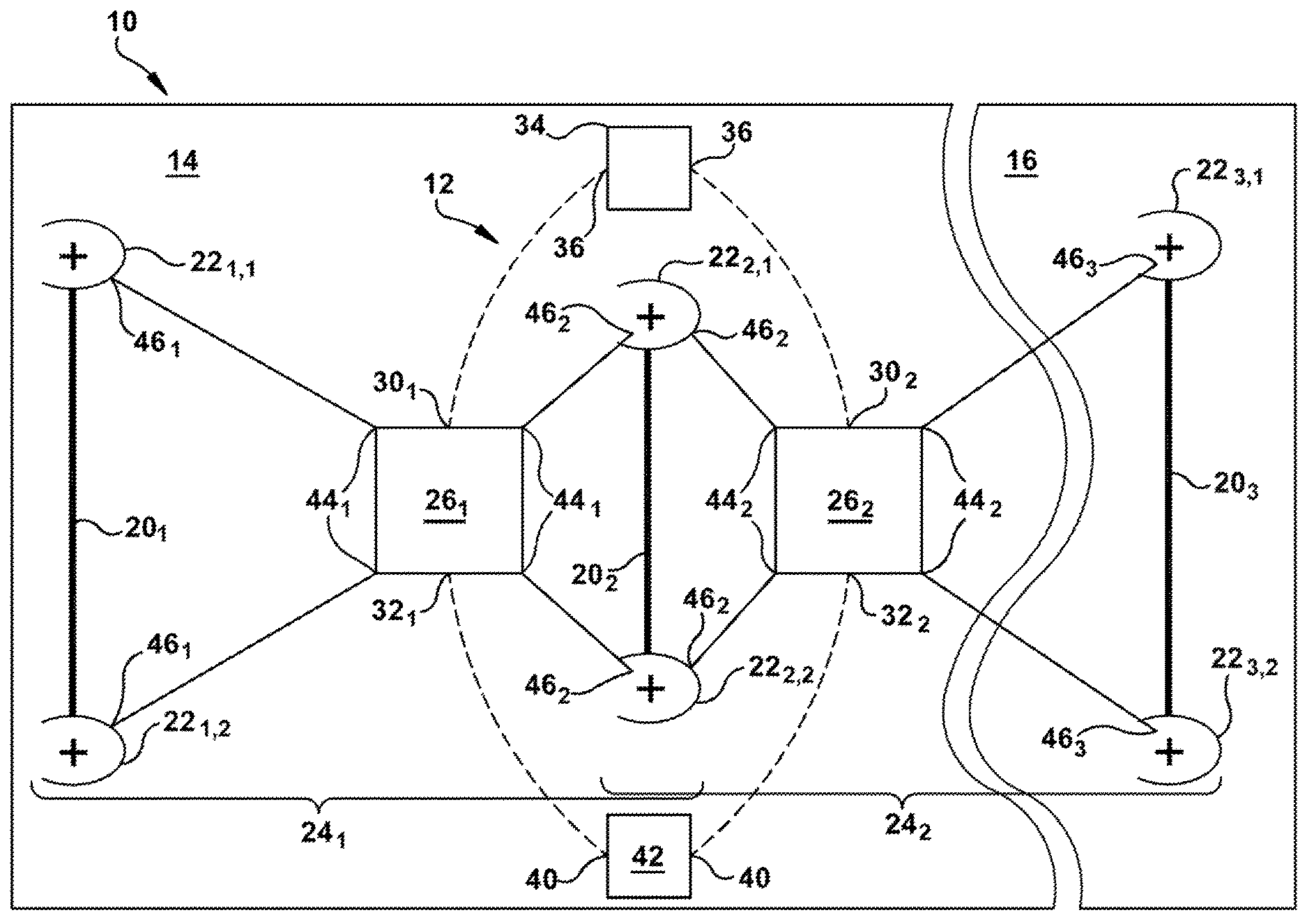
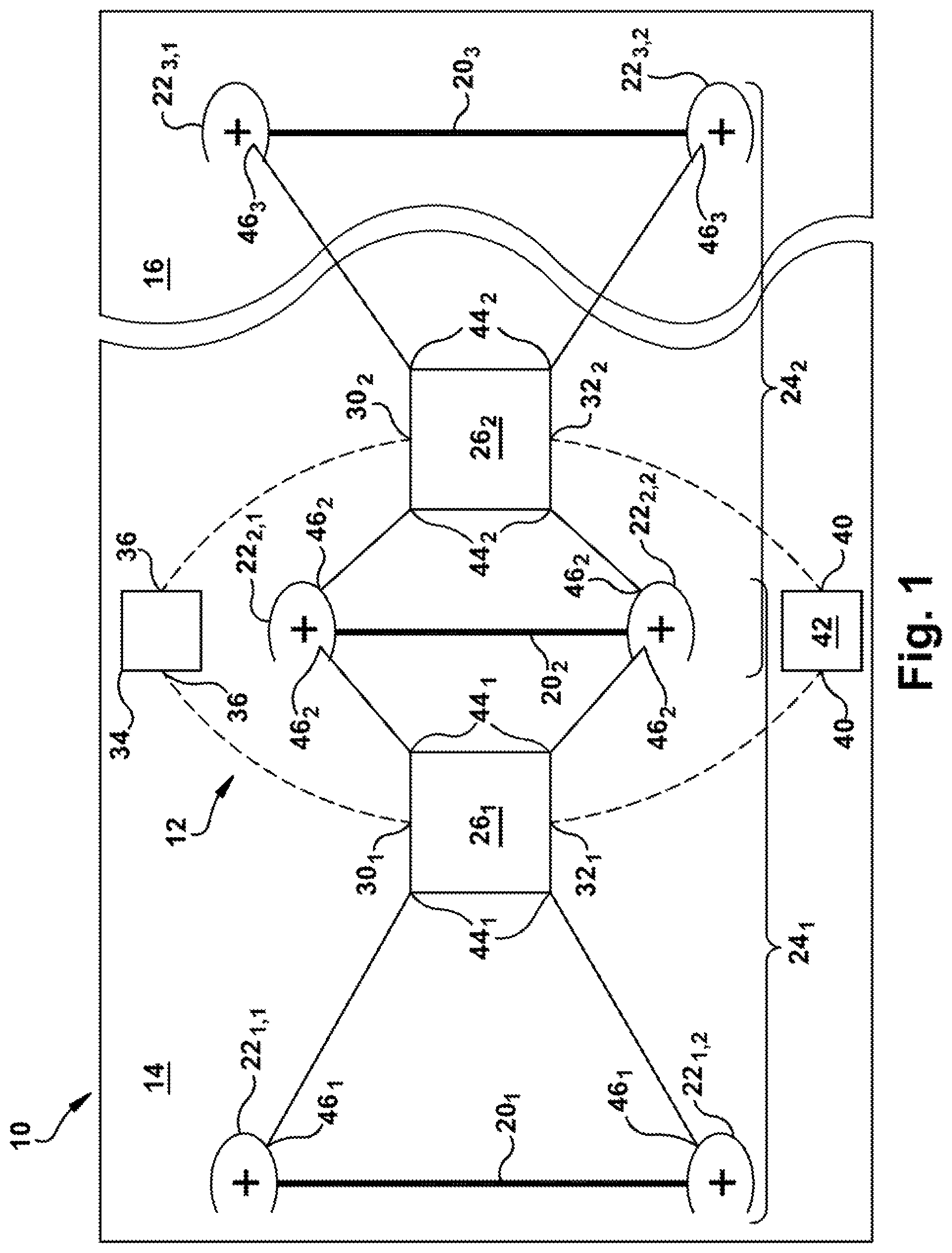
With reference to FIG. 1, a simplified component diagram of a combination vehicle 10 including an exemplary braking system 12 is illustrated in accordance with one embodiment of the present invention. In the illustrated embodiment, the combination vehicle 10 is an articulated vehicle including a first portion 14 (e.g., a tractor portion) and a second portion 16 (e.g., a trailer portion).
The combination vehicle 10 includes a plurality of axles 20 (e.g., brake axles). For example, three (3) axles 20.sub.1,2,3 (collectively 20) are shown in the illustrated embodiment. The first and second axles 20.sub.1,2 are included on the tractor portion 14 of the vehicle 10, and the axle 20.sub.3 is included on the trailer portion 16 of the vehicle 10. In one embodiment, the first axle 20.sub.1 is a steer axle on the tractor portion 14; the second axle 20.sub.1 is a drive axle on the tractor portion 14; and the third axle 20.sub.3 is a trailer axle on the trailer portion 16. It is to be understood that any number of axles in any configuration distributed between the tractor portion 14 and the trailer portion 16 of the vehicle 10 are contemplated.
Each of the axles 20 includes at least one respective actuatable brake 22. For example, the first axle 20.sub.1 includes first actuatable brakes 22.sub.1 (e.g., actuatable brakes 22.sub.1,1 and 22.sub.1,2); the second axle 20.sub.2 includes second actuatable brakes 22.sub.2 (e.g., actuatable brakes 22.sub.2,1 and 22.sub.2,2); and the third axle 20.sub.3 includes third actuatable brakes 22.sub.3 (e.g., actuatable brakes 22.sub.3,1 and 22.sub.3,2). The brakes 22.sub.1,1; 22.sub.1,2; 22.sub.2,1, 22.sub.2,2; and 22.sub.3,1, 22.sub.3,2 are collectively referenced as 22.
The first axle 20.sub.1 and the first actuatable brake 22.sub.1 are included in a first brake group 24.sub.1. The second axle 20.sub.2 and the second actuatable brake 22.sub.2 are included in both the first brake group 24.sub.1 and a second brake group 24.sub.2. The third axle 20.sub.3 and the third actuatable brake 22.sub.3 are included in the second brake group 24.sub.2.
A first valve 26.sub.1 controls actuation of the first and second actuatable brakes 22.sub.1,2 (e.g., the first brake group 24.sub.1), and a second valve 26.sub.2 controls actuation of the second and third actuatable brakes 22.sub.2,3 (e.g., the first brake group 24.sub.1). In one embodiment, the first and second valves 26.sub.1,2 (collectively 26) are both in the tractor portion 14 of the vehicle 10. However, other embodiments in which at least one of the valves 26 is on the trailer portion 16 of the vehicle 10 are contemplated. In any embodiment, it is contemplated that the first valves 26.sub.1,2 are solenoid valves.
It is also contemplated the first and second valves 26 are control valves that receive both a pneumatic control signal at respective pneumatic control signal ports 30.sub.1,2 (collectively 30) and respective electronic control signal ports 32.sub.1,2 (collectively 32).
A foot brake valve 34 (e.g., pedal) is depressed by an operator of the vehicle 10 to cause at least one of the brakes 22 to be actuated (e.g., to brake the vehicle 10) during a manual braking event. A pressure of a pneumatic fluid delivered from a foot brake delivery port 36 of the foot brake valve 34 is fluidly communicated (e.g., transmitted) to the respective pneumatic control signal ports 30.sub.1,2 of the first and second valves 26 as respective pneumatic control signals. The pneumatic control signals fluidly delivered to the respective pneumatic control signal ports 30.sub.1,2 are based on how much the operator depresses the foot brake valve 34. Braking of the vehicle 10 achieved in response to the foot brake valve 34 being depressed by the operator is referred to as a manual braking event. Therefore, in this embodiment, the first and second valves 26 receive pneumatic control signals during the manual braking event and the respective pneumatic control signals are manually controlled by application of the foot brake valve 34 by the operator.
An electrical delivery port 40 of an electronic control unit 42 (ECU) electrically communicates with the respective electronic control signal ports 32.sub.1,2 of the first and second valves 26. During an automatic braking event (e.g., an adaptive cruise control (ACC) braking event, an antilock brake system (ABS) braking event, etc.), the ECU 42 electrically communicates (e.g., transmits) electronic signals from the electrical ECU delivery port 40 to the respective electronic control signal ports 32.sub.1,2 of the first and second valves 26 as respective electronic control signals to cause at least one of the brakes 22 to be actuated (e.g., to brake the vehicle 10). Since the electronic control signals are communicated during an automatic braking event, these signals are referred to as automatically controlled braking signals. In one embodiment, it is contemplated the ECU 42 is an anti-lock braking system (ABS) controller that transmits the electronic control signals to the first and second valves 26 during an ABS event (i.e., an automatic braking event).
During normal operation, at least one of the foot brake valve 34 and the ECU 42 transmits the pneumatic control signals and/or the electronic control signals to the respective control ports 30, 32 of both the first and second valves 26.sub.1,2. The first valve 26.sub.1 transmits a pneumatic fluid from a first valve supply port (not shown) to a first valve delivery port 44.sub.1 based on the control signals received at the pneumatic and electronic control ports 30.sub.1, 32.sub.1, respectively. Similarly, the second valve 26.sub.2 transmits the pneumatic fluid from a second valve supply port (not shown) to a second valve delivery port 44.sub.2 based on the control signals received at the pneumatic and electronic control ports 30.sub.2, 32.sub.2, respectively. The control signals received at the pneumatic and electronic control ports 30.sub.1, 32.sub.1, respectively, control operation of the first valve 26.sub.1 independently of each other. Similarly, the control signals received at the pneumatic and electronic control ports 30.sub.2, 32.sub.2, respectively, control operation of the second valve 26.sub.2 independently of each other.
For example, if neither the pneumatic control signal nor the electronic control signal is received at the respective control ports 30.sub.1, 32.sub.1, the first valve 26.sub.1 does not transmit the pneumatic fluid from the first valve supply port (not shown) to the first valve delivery port 44.sub.1. Otherwise, if at least one of the pneumatic control signal and the electronic control signal is received at the respective control ports 30.sub.1, 32.sub.1, the first valve 26.sub.1 does transmit the pneumatic fluid from the first valve supply port (not shown) to the first valve delivery port 44.sub.1. It is contemplated that the amount of pneumatic fluid (e.g., the pressure of the pneumatic fluid) transmitted from the first valve supply port (not shown) to the first valve delivery port 44.sub.1 is based on (e.g., proportional or linearly proportional to) the pressure of the pneumatic fluid at the pneumatic control port 30.sub.1. On the other hand, while the amount of pneumatic fluid (e.g., the pressure of the pneumatic fluid) transmitted from the first valve supply port (not shown) to the first valve delivery port 44.sub.1 is based on the electronic control signal being present at the control port 32, it is not contemplated to be a proportional relationship.
The second valve 26.sub.2 operates in a similar manner to the first valve 26.sub.2 with regard to transmitting the pneumatic fluid from the second valve supply port (not shown) to the second valve delivery port 44.sub.2 based on the pneumatic and electronic control signals at the control ports 30.sub.2, 32.sub.2, respectively.
Each of the actuatable brakes 22.sub.1,2,3 includes a respective control port 46.sub.1,2,3 (e.g., a pneumatic control port). The control port 46.sub.1 fluidly communicates with the first valve delivery port 44.sub.1; the control port 46.sub.2 fluidly communicates with both the first valve delivery port 44.sub.1 and the second valve delivery port 44.sub.2; and the control port 46.sub.3 fluidly communicates with the second valve delivery port 44.sub.2.
The brakes 22.sub.1,2,3 actuate based on the pressure of the pneumatic fluid present at the respective control ports 46.sub.1,2,3. More specifically, the first and second actuatable brakes 22.sub.1,2 actuate based on the pneumatic pressure at the delivery port 44.sub.1 of the first valve 26.sub.1; and the second and third actuatable brakes 22.sub.2,3 actuate based on the pneumatic pressure at the delivery port 44.sub.2 of the second valve 26.sub.2. Since the second control port 46.sub.2 fluidly communicates with both the delivery port 44.sub.1 of the first valve 26.sub.1 and the delivery port 44.sub.1 of the second valve 26.sub.2, the second actuatable brakes 22.sub.2 actuate based on either the pneumatic pressure at the delivery port 44.sub.1 of the first valve 26.sub.1 or the pneumatic pressure at the delivery port 44.sub.2 of the second valve 26.sub.2. For example, the second actuatable brakes 22.sub.2 actuate based on the higher of the pneumatic pressures at the delivery ports 44.sub.1,2. In another embodiment, another valve (e.g., a double-check valve) (not shown) arbitrates between the pneumatic pressure at the delivery port 44.sub.1 and the pneumatic pressure at the delivery port 44.sub.2 for actuating the second actuatable brakes 22.sub.2.
In the event of a malfunction (e.g., failure), insufficient pneumatic pressure may be available at the first valve delivery port 44.sub.1 to actuate the first and second brakes 22.sub.1,2 when desired. For example, a leak may reduce the supply pressure of the pneumatic fluid available to pass from the first valve supply port (not shown) to the first valve delivery port 44.sub.1. Alternatively, the first valve 26.sub.1 may simply fail to change states and pass the pneumatic fluid from the first valve supply port (not shown) to the first valve delivery port 44.sub.1 even when at least one of the appropriate control signals requesting the fluid communication between the first valve supply port (not shown) and the first valve delivery port 44.sub.1 is present at the control ports 30.sub.1, 32.sub.1.
A malfunction may also cause insufficient pneumatic pressure to be available at the second valve delivery port 44.sub.2 to actuate the second and third brakes 22.sub.2,3 when desired. For example, a leak may reduce the supply pressure of the pneumatic fluid available to pass from the second valve supply port (not shown) to the second valve delivery port 44.sub.2. Alternatively, the second valve 26.sub.2 may simply fail to change states and pass the pneumatic fluid from the second valve supply port (not shown) to the second valve delivery port 44.sub.2 even when at least one of the appropriate control signals requesting the fluid communication between the second valve supply port (not shown) and the second valve delivery port 44.sub.2 is present at the control ports 30.sub.2, 32.sub.2.
Because the second actuatable brakes 22.sub.2 actuate based on either the pneumatic pressure at the delivery port 44.sub.1 or the pneumatic pressure at the delivery port 44.sub.2, the second actuatable brakes 22.sub.2 actuate when either the first valve 26.sub.1 or the second valve 26.sub.2 transmit the pneumatic fluid from the respective valve supply port (not shown) to the respective valve delivery port 44.sub.1,2. Therefore, although a malfunction causing insufficient pneumatic pressure to be available at one of the first valve delivery port 44.sub.1 and the second valve delivery port 44.sub.2 may cause one of the first brakes 22.sub.1 and the third brakes 22.sub.3 to be actuated, it is contemplated that sufficient pneumatic pressure will still be available at the other of the first valve delivery port 44.sub.1 and the second valve delivery port 44.sub.2 to actuate the other of the first brakes 22.sub.1 and the third brakes 22.sub.3.
Since the second brakes 22.sub.2 are actuated even when a malfunction causes either the first valve 26.sub.1 or the second valve 26.sub.2 to not transmit the pneumatic fluid from the respective valve supply port (not shown) to the respective valve delivery port 44.sub.1,2, two (2) of the three (3) brakes 22.sub.1,2,3 are actuated during such a malfunction. For example, if a malfunction causes the first valve 26.sub.1 to not transmit sufficient pneumatic fluid from the valve supply port (not shown) to the valve delivery port 44.sub.1 to actuate the first and second brakes 22.sub.1,2, it is contemplated that the second valve 26.sub.2 still transmits sufficient pneumatic fluid from the valve supply port (not shown) to the valve delivery port 44.sub.2 to actuate the second and third brakes 22.sub.2,3. Similarly, if a malfunction causes the second valve 26.sub.2 to not transmit sufficient pneumatic fluid from the valve supply port (not shown) to the valve delivery port 44.sub.2 to actuate the second and third brakes 22.sub.2,3, it is contemplated that the first valve 26.sub.1 still transmits sufficient pneumatic fluid from the valve supply port (not shown) to the valve delivery port 44.sub.1 to actuate the first and second brakes 22.sub.1,2.
The first valve 26.sub.1, the second valve 26.sub.2, the brake pedal 34, and the ECU 42 act as a means for independently controlling the first group 24.sub.1 of the actuatable brakes 22.sub.1,2 and the second group 24.sub.2 of the actuatable brakes 22.sub.2,3, where one of the actuatable brakes 22.sub.2 is included in both the first and second groups 24.sub.1,2 of the actuatable brakes 22, and where one of the first and second groups 24.sub.1,2 of the actuatable brakes 22.sub.1,3 is continued to be controlled if the other of the first and second groups 24.sub.1,2 of the actuatable brakes 22.sub.1,3 fails to be controlled.
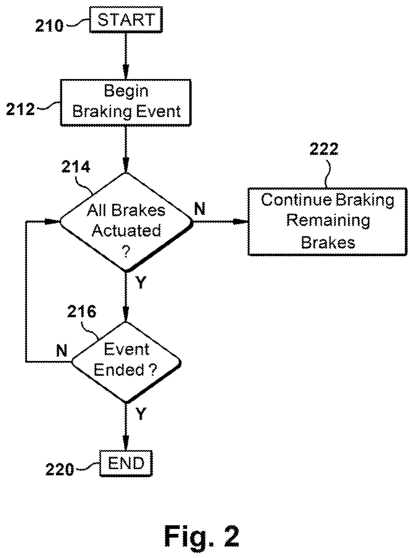
With reference to FIG. 2, an exemplary methodology of the system shown in FIG. 1 for braking a vehicle combination is illustrated. As illustrated, the blocks represent functions, actions and/or events performed therein. It will be appreciated that electronic and software systems involve dynamic and flexible processes such that the illustrated blocks and described sequences can be performed in different sequences. It will also be appreciated by one of ordinary skill in the art that elements embodied as software may be implemented using various programming approaches such as machine language, procedural, object-oriented or artificial intelligence techniques. It will further be appreciated that, if desired and appropriate, some or all of the software can be embodied as part of a device's operating system.
With reference to FIGS. 1 and 2, the method starts in at step 210. Then, in a step 212, a vehicle braking event begins. For example, the braking event begins when at least one of i) the operator of the vehicle 10 depresses the pedal 34 to transmit pneumatic control signals to the pneumatic control ports 30 of the respective valves 26 to initiate a manual braking event and ii) the ECU 42 transmits electronic control signals to the electronic control ports 32 of the respective valves 26 to initiate an automatic braking event.
In a step 214, the ECU 42 monitors the brakes 22 to determine if the brakes 22 are actuated as demanded by the at least one of the manual braking event and the automatic braking event. If it is determined in the step 214 that the brakes 22 are actuated as demanded (e.g., no failure has occurred to either the valves 26 or the brakes 22), control passes to a step 216 to determine if the at least one braking event has ended. If it is determined in the step 216 that the at least one braking event has ended, control passes to a step 220 to end the method. Otherwise, if it is determined in the step 216 that the at least one braking event has not ended, control returns to the step 214.
If it is determined in the step 214 that the brakes 22 in one of the brake groups 24.sub.1,2 are not actuated as demanded (e.g., a failure has occurred in either the valves 26 or the brakes 22), control passes to a step 222 to continue actuating the at least one of the other brake groups 24.sub.1,2. Control then passes to the step 216 to determine if the at least one braking event has ended.
While the present invention has been illustrated by the description of embodiments thereof, and while the embodiments have been described in considerable detail, it is not the intention of the applicants to restrict or in any way limit the scope of the appended claims to such detail. Additional advantages and modifications will readily appear to those skilled in the art. Therefore, the invention, in its broader aspects, is not limited to the specific details, the representative apparatus, and illustrative examples shown and described. Accordingly, departures may be made from such details without departing from the spirit or scope of the applicant's general inventive concept.
* * * * *
D00000
D00001
D00002
XML
uspto.report is an independent third-party trademark research tool that is not affiliated, endorsed, or sponsored by the United States Patent and Trademark Office (USPTO) or any other governmental organization. The information provided by uspto.report is based on publicly available data at the time of writing and is intended for informational purposes only.
While we strive to provide accurate and up-to-date information, we do not guarantee the accuracy, completeness, reliability, or suitability of the information displayed on this site. The use of this site is at your own risk. Any reliance you place on such information is therefore strictly at your own risk.
All official trademark data, including owner information, should be verified by visiting the official USPTO website at www.uspto.gov. This site is not intended to replace professional legal advice and should not be used as a substitute for consulting with a legal professional who is knowledgeable about trademark law.