Connector assemblies with bending limiters for electrical stimulation systems and methods of making and using same
Nageri , et al. Ja
U.S. patent number 10,543,374 [Application Number 15/715,974] was granted by the patent office on 2020-01-28 for connector assemblies with bending limiters for electrical stimulation systems and methods of making and using same. This patent grant is currently assigned to BOSTON SCIENTIFIC NEUROMODULATION CORPORATION. The grantee listed for this patent is Boston Scientific Neuromodulation Corporation. Invention is credited to Ranjan Krishna Mukhari Nageri, Geoffrey Abellana Villarta.


| United States Patent | 10,543,374 |
| Nageri , et al. | January 28, 2020 |
Connector assemblies with bending limiters for electrical stimulation systems and methods of making and using same
Abstract
A connector assembly includes an elongated connector housing defining a port at the second end of the connector housing for receiving a proximal end of a lead or lead extension; a lumen that extends from the port along at least a portion of the length of the connector housing; connector contacts axially spaced-apart and disposed along the lumen; and non-conductive spacers disposed between adjacent connector contacts, at least one of the non-conductive spacers includes a first region. One or more additional features are included to resist bending of the connector assembly. One such feature is a non-conductive first insert disposed between adjacent connector contacts to maintains a minimum distance between the adjacent connector contacts. Another feature is a stiffening element disposed within apertures in the spacers and connecting two or more of the spacers. Yet another feature is a stiffening sleeve disposed within the housing.
| Inventors: | Nageri; Ranjan Krishna Mukhari (Valencia, CA), Villarta; Geoffrey Abellana (Valencia, CA) | ||||||||||
|---|---|---|---|---|---|---|---|---|---|---|---|
| Applicant: |
|
||||||||||
| Assignee: | BOSTON SCIENTIFIC NEUROMODULATION
CORPORATION (Valencia, CA) |
||||||||||
| Family ID: | 61757566 | ||||||||||
| Appl. No.: | 15/715,974 | ||||||||||
| Filed: | September 26, 2017 |
Prior Publication Data
| Document Identifier | Publication Date | |
|---|---|---|
| US 20180093098 A1 | Apr 5, 2018 | |
Related U.S. Patent Documents
| Application Number | Filing Date | Patent Number | Issue Date | ||
|---|---|---|---|---|---|
| 62402715 | Sep 30, 2016 | ||||
| Current U.S. Class: | 1/1 |
| Current CPC Class: | A61N 1/05 (20130101); A61N 1/0551 (20130101); A61N 1/3605 (20130101); A61N 1/3752 (20130101); H01R 24/58 (20130101); H01R 13/15 (20130101) |
| Current International Class: | A61N 1/375 (20060101); H01R 24/58 (20110101); A61N 1/36 (20060101); A61N 1/05 (20060101); H01R 13/15 (20060101) |
| Field of Search: | ;439/752,668,669 |
References Cited [Referenced By]
U.S. Patent Documents
| 3222471 | December 1965 | Steinkamp |
| 3601747 | August 1971 | Prall et al. |
| 3718142 | February 1973 | Mulier |
| 3757789 | September 1973 | Shenker |
| 3771106 | November 1973 | Matsumoto et al. |
| 3908668 | September 1975 | Bolduc |
| 3951154 | April 1976 | Hartlaub |
| 3990727 | November 1976 | Gallagher |
| 4003616 | January 1977 | Springer |
| 4112953 | September 1978 | Shanker et al. |
| 4142532 | March 1979 | Ware |
| 4180078 | December 1979 | Anderson |
| 4245642 | January 1981 | Skubitz et al. |
| 4259962 | April 1981 | Peers-Trevarton |
| 4310001 | January 1982 | Comben |
| 4364625 | December 1982 | Baker et al. |
| 4367907 | January 1983 | Buck |
| 4411276 | October 1983 | Dickhudt |
| 4411277 | October 1983 | Dickhudt |
| 4461194 | July 1984 | Moore |
| 4466441 | August 1984 | Skubitz et al. |
| 4516820 | May 1985 | Kuzma |
| RE31990 | September 1985 | Sluetz et al. |
| 4540236 | September 1985 | Peers-Trevarton |
| 4602624 | July 1986 | Naples et al. |
| 4603696 | August 1986 | Cross, Jr. et al. |
| 4614395 | September 1986 | Peers-Trevarton |
| 4630611 | December 1986 | King |
| 4695116 | September 1987 | Bailey et al. |
| 4695117 | September 1987 | Kysiak |
| 4712557 | December 1987 | Harris |
| 4715380 | December 1987 | Harris |
| 4744370 | May 1988 | Harris |
| 4784141 | November 1988 | Peers-Trevarton |
| 4832032 | May 1989 | Schneider |
| 4840580 | June 1989 | Saell et al. |
| 4850359 | July 1989 | Putz |
| 4860750 | August 1989 | Frey et al. |
| 4867708 | September 1989 | Iizuka |
| 4869255 | September 1989 | Putz |
| 4898173 | February 1990 | Daglow et al. |
| 4899753 | February 1990 | Inoue et al. |
| 4951687 | August 1990 | Ufford et al. |
| 4995389 | February 1991 | Harris |
| 5000177 | March 1991 | Hoffmann et al. |
| 5000194 | March 1991 | van den Honert et al. |
| 5007435 | April 1991 | Doan et al. |
| 5007864 | April 1991 | Stutz, Jr. |
| 5070605 | December 1991 | Daglow et al. |
| 5082453 | January 1992 | Stutz, Jr. |
| 5086773 | February 1992 | Ware |
| 5135001 | August 1992 | Sinofsky et al. |
| 5193539 | March 1993 | Schulman et al. |
| 5193540 | March 1993 | Schulman et al. |
| 5201865 | April 1993 | Kuehn |
| 5241957 | September 1993 | Camps et al. |
| 5252090 | October 1993 | Giurtino et al. |
| 5261395 | November 1993 | Oleen et al. |
| 5312439 | May 1994 | Loeb |
| 5324312 | June 1994 | Stokes et al. |
| 5330521 | July 1994 | Cohen |
| 5336246 | August 1994 | Dantanarayana |
| 5348481 | September 1994 | Ortiz |
| 5354326 | October 1994 | Comben et al. |
| 5358514 | October 1994 | Schulman et al. |
| 5368496 | November 1994 | Ranalletta et al. |
| 5374279 | December 1994 | Duffin, Jr. et al. |
| 5374285 | December 1994 | Vaiani et al. |
| 5383913 | January 1995 | Schiff |
| 5413595 | May 1995 | Stutz, Jr. |
| 5433734 | July 1995 | Stokes et al. |
| 5435731 | July 1995 | Kang |
| 5458629 | October 1995 | Baudino et al. |
| 5486202 | January 1996 | Bradshaw |
| 5489225 | February 1996 | Julian |
| 5509928 | April 1996 | Acken |
| 5522874 | June 1996 | Gates |
| 5534019 | July 1996 | Paspa |
| 5545138 | August 1996 | Bradshaw et al. |
| 5545189 | August 1996 | Fayram |
| 5582180 | August 1996 | Manset et al. |
| 5560358 | October 1996 | Arnold et al. |
| 5679026 | October 1997 | Fain et al. |
| 5683433 | November 1997 | Carson |
| 5711316 | January 1998 | Elsberry et al. |
| 5713922 | February 1998 | King |
| 5720631 | February 1998 | Carson et al. |
| 5730628 | March 1998 | Hawkins |
| 5755743 | May 1998 | Volz et al. |
| 5766042 | June 1998 | Ries et al. |
| 5782892 | July 1998 | Castle et al. |
| 5796044 | August 1998 | Cobian et al. |
| 5800350 | September 1998 | Coppleson et al. |
| 5800495 | September 1998 | Machek et al. |
| 5807144 | September 1998 | Sivard |
| 5837006 | November 1998 | Ocel et al. |
| 5843141 | December 1998 | Bischoff et al. |
| 5843143 | December 1998 | Gijsbers et al. |
| 5906634 | May 1999 | Flynn et al. |
| 5931861 | August 1999 | Werner et al. |
| 5938688 | August 1999 | Schiff |
| 5951595 | September 1999 | Moberg et al. |
| 5957968 | September 1999 | Belden |
| 5968082 | October 1999 | Heil |
| 5987361 | November 1999 | Mortimer |
| 5989077 | November 1999 | Mast et al. |
| 6006135 | December 1999 | Kast et al. |
| 6018684 | January 2000 | Bartig et al. |
| 6038479 | March 2000 | Werner et al. |
| 6038481 | March 2000 | Werner et al. |
| 6042432 | March 2000 | Hashazawa et al. |
| 6051017 | April 2000 | Loeb et al. |
| 6080188 | June 2000 | Rowley et al. |
| 6112120 | August 2000 | Correas |
| 6112121 | August 2000 | Paul et al. |
| 6125302 | September 2000 | Kuzma |
| 6134478 | October 2000 | Spehr |
| 6154678 | November 2000 | Lauro |
| 6161047 | December 2000 | King et al. |
| 6162101 | December 2000 | Fischer et al. |
| 6164284 | December 2000 | Schulman et al. |
| 6167311 | December 2000 | Rezal |
| 6167314 | December 2000 | Fischer, Sr. et al. |
| 6175710 | January 2001 | Kamaji et al. |
| 6181969 | January 2001 | Gord |
| 6185452 | February 2001 | Schulman et al. |
| 6192278 | February 2001 | Werner et al. |
| 6198969 | March 2001 | Kuzma |
| 6208894 | March 2001 | Schulman et al. |
| 6224450 | May 2001 | Norton |
| 6271094 | August 2001 | Boyd et al. |
| 6295944 | October 2001 | Lovett |
| 6319021 | November 2001 | Billman |
| 6321126 | November 2001 | Kuzma |
| 6322559 | November 2001 | Daulton et al. |
| 6343233 | January 2002 | Werner et al. |
| 6364278 | April 2002 | Lin et al. |
| 6370434 | April 2002 | Zhang et al. |
| 6391985 | May 2002 | Goode et al. |
| 6397108 | May 2002 | Camps et al. |
| 6415168 | July 2002 | Putz |
| 6428336 | August 2002 | Akerfeldt |
| 6428368 | August 2002 | Hawkins et al. |
| 6430442 | August 2002 | Peters et al. |
| 6466824 | October 2002 | Struble |
| 6473654 | October 2002 | Chinn |
| 6498952 | December 2002 | Imani et al. |
| 6510347 | January 2003 | Borkan |
| 6516227 | February 2003 | Meadows et al. |
| 6556873 | April 2003 | Smits |
| 6564078 | May 2003 | Marino et al. |
| 6604283 | August 2003 | Kuzma |
| 6605094 | August 2003 | Mann et al. |
| 6609029 | August 2003 | Mann et al. |
| 6609032 | August 2003 | Woods et al. |
| 6654641 | November 2003 | Froberg |
| 6662035 | December 2003 | Sochor |
| 6663570 | December 2003 | Mott |
| 6671534 | December 2003 | Putz |
| 6671553 | December 2003 | Helland et al. |
| 6678564 | January 2004 | Ketterl et al. |
| 6725096 | April 2004 | Chinn et al. |
| 6741892 | May 2004 | Meadows et al. |
| 6757039 | June 2004 | Ma |
| 6757970 | July 2004 | Kuzma et al. |
| 6799991 | October 2004 | Williams et al. |
| 6805675 | October 2004 | Gardeski et al. |
| 6854994 | February 2005 | Stein et al. |
| 6878013 | April 2005 | Behan |
| 6895276 | May 2005 | Kast et al. |
| 6913478 | July 2005 | Lamrey |
| 6921295 | July 2005 | Sommer et al. |
| 6968235 | November 2005 | Belden et al. |
| 6980863 | December 2005 | van Venrooj et al. |
| 7027852 | April 2006 | Helland |
| 7047084 | May 2006 | Erickson et al. |
| 7058452 | June 2006 | Dahberg |
| 7069081 | June 2006 | Biggs et al. |
| 7083474 | August 2006 | Fleck et al. |
| 7108549 | September 2006 | Lyu et al. |
| 7110827 | September 2006 | Sage et al. |
| 7128600 | October 2006 | Osypka |
| 7155283 | December 2006 | Ries et al. |
| 7164951 | January 2007 | Ries et al. |
| 7168165 | January 2007 | Calzada et al. |
| 7191009 | March 2007 | Laske et al. |
| 7195523 | March 2007 | Naviaux |
| 7203548 | April 2007 | Whitehurst et al. |
| 7225034 | May 2007 | Ries et al. |
| 7231253 | June 2007 | Tidemand et al. |
| 7241180 | July 2007 | Rentas |
| 7242987 | July 2007 | Holleman et al. |
| 7244150 | July 2007 | Brase et al. |
| 7270568 | September 2007 | Osypka |
| 7283878 | October 2007 | Brostrom et al. |
| 7286882 | October 2007 | Cole |
| 7287995 | October 2007 | Stein et al. |
| 7292890 | November 2007 | Whitehurst et al. |
| 7396335 | July 2008 | Gardeski et al. |
| 7402083 | July 2008 | Kast et al. |
| 7422487 | September 2008 | Osypka |
| 7430958 | October 2008 | Wong |
| 7437193 | October 2008 | Parramon et al. |
| 7450997 | November 2008 | Pianca et al. |
| 7489971 | February 2009 | Franz |
| 7512446 | March 2009 | Honeck |
| 7516447 | April 2009 | Marvin et al. |
| 7526339 | April 2009 | Lahti et al. |
| 7539542 | May 2009 | Malinowski |
| 7548788 | June 2009 | Chinn et al. |
| 7554493 | June 2009 | Rahman |
| 7583999 | September 2009 | Bedenbaugh |
| 7585190 | September 2009 | Osypka |
| 7590451 | September 2009 | Tronnes et al. |
| 7650184 | January 2010 | Walter |
| 7654843 | February 2010 | Olson |
| 7668601 | February 2010 | Hegland et al. |
| 7672734 | March 2010 | Anderson et al. |
| 7736191 | June 2010 | Sochor |
| 7758384 | July 2010 | Alexander et al. |
| 7761165 | July 2010 | He et al. |
| 7761985 | July 2010 | Hegland et al. |
| 7783359 | August 2010 | Meadows |
| 7792590 | September 2010 | Pianca et al. |
| 7798864 | September 2010 | Barker et al. |
| 7803021 | September 2010 | Brase |
| 7809446 | October 2010 | Meadows |
| 7822477 | October 2010 | Rey et al. |
| 7822482 | October 2010 | Gerber |
| 7840188 | November 2010 | Kurokawa |
| 7848802 | December 2010 | Goetz |
| 7856707 | December 2010 | Cole |
| 7860570 | December 2010 | Whitehurst et al. |
| 7949395 | May 2011 | Kuzma |
| 7974705 | July 2011 | Zdeblick et al. |
| 7974706 | July 2011 | Moffitt et al. |
| 7979140 | July 2011 | Schulman |
| 8000808 | August 2011 | Hegland et al. |
| 8019440 | September 2011 | Kokones et al. |
| 8036755 | October 2011 | Franz |
| 8041309 | October 2011 | Kurokawa |
| 8046073 | October 2011 | Pianca |
| 8046074 | October 2011 | Barker |
| 8078280 | December 2011 | Sage |
| 8099177 | January 2012 | Dahlberg |
| 8100726 | January 2012 | Harlan et al. |
| 8140163 | March 2012 | Daglow et al. |
| 8167660 | May 2012 | Dilmaghanian et al. |
| 8175710 | May 2012 | He |
| 8190259 | May 2012 | Smith et al. |
| 8206180 | June 2012 | Kast et al. |
| 8224450 | July 2012 | Brase |
| 8225504 | July 2012 | Dye et al. |
| 8239042 | August 2012 | Chinn et al. |
| 8271094 | September 2012 | Moffitt et al. |
| 8295944 | October 2012 | Howard et al. |
| 8301255 | October 2012 | Barker |
| 8321025 | November 2012 | Bedenbaugh |
| 8342887 | January 2013 | Gleason et al. |
| 8359107 | January 2013 | Pianca et al. |
| 8364278 | January 2013 | Pianca et al. |
| 8391985 | March 2013 | McDonald |
| 8412330 | April 2013 | Kast et al. |
| 8527054 | September 2013 | North |
| 8583237 | November 2013 | Bedenbaugh |
| 8600507 | December 2013 | Brase et al. |
| 8682439 | March 2014 | DeRohan |
| 8688235 | April 2014 | Pianca et al. |
| 8738138 | May 2014 | Funderburk |
| 8784143 | July 2014 | Edgell et al. |
| 8831742 | September 2014 | Pianca et al. |
| 8849396 | September 2014 | DeRohan et al. |
| 8849415 | September 2014 | Bedenbaugh |
| 8897876 | November 2014 | Sundaramurthy et al. |
| 8897891 | November 2014 | Romero |
| 8968331 | March 2015 | Sochor |
| 9101775 | August 2015 | Barker |
| 9149630 | October 2015 | Howard et al. |
| 9162048 | October 2015 | Romero et al. |
| 9162055 | October 2015 | Pianca |
| 9234591 | January 2016 | Dilmaghanian et al. |
| 9270070 | February 2016 | Pianca |
| 9289596 | March 2016 | Leven |
| 9352147 | May 2016 | Nguyen-stella et al. |
| 9381348 | July 2016 | Romero et al. |
| 9403022 | August 2016 | Ries et al. |
| 9409032 | August 2016 | Brase et al. |
| 9440066 | September 2016 | Black |
| 9492666 | November 2016 | Smith |
| 9498618 | November 2016 | Stetson et al. |
| 9498820 | November 2016 | Romero et al. |
| 9504839 | November 2016 | Leven |
| 9604068 | March 2017 | Malinowski |
| 9656093 | May 2017 | Villarta et al. |
| 9770598 | September 2017 | Malinowski et al. |
| 9775988 | October 2017 | Govea |
| 9782582 | October 2017 | Govea |
| 9839787 | December 2017 | Villarta |
| 9855413 | January 2018 | Vadlamudi |
| 9878148 | January 2018 | Leven |
| 2001/0023368 | September 2001 | Black et al. |
| 2002/0143376 | October 2002 | Chinn et al. |
| 2002/0156513 | October 2002 | Borkan |
| 2002/0183817 | December 2002 | Van Venrooij et al. |
| 2003/0163171 | August 2003 | Kast |
| 2004/0064164 | April 2004 | Ries et al. |
| 2004/0230268 | November 2004 | Huff et al. |
| 2004/0260373 | December 2004 | Ries et al. |
| 2005/0015130 | January 2005 | Gill |
| 2005/0027326 | February 2005 | Ries et al. |
| 2005/0027327 | February 2005 | Ries et al. |
| 2005/0038489 | February 2005 | Grill |
| 2005/0043770 | February 2005 | Hine et al. |
| 2005/0043771 | February 2005 | Sommer et al. |
| 2005/0137665 | June 2005 | Cole |
| 2005/0171587 | August 2005 | Daglow et al. |
| 2005/0186829 | August 2005 | Balsells |
| 2005/0272280 | December 2005 | Osypka |
| 2006/0015163 | January 2006 | Brown |
| 2006/0025841 | February 2006 | McIntyre |
| 2006/0030918 | February 2006 | Chinn |
| 2006/0167522 | July 2006 | Malinowski |
| 2006/0224208 | October 2006 | Naviaux |
| 2006/0247697 | November 2006 | Sharma et al. |
| 2006/0247749 | November 2006 | Colvin |
| 2006/0259106 | November 2006 | Arnholdt et al. |
| 2007/0042648 | February 2007 | Balsells |
| 2007/0142889 | June 2007 | Whitehurst et al. |
| 2007/0150036 | June 2007 | Anderson |
| 2007/0161294 | July 2007 | Brase et al. |
| 2007/0168007 | July 2007 | Kuzma et al. |
| 2007/0203546 | August 2007 | Stone et al. |
| 2007/0219551 | September 2007 | Honour |
| 2007/0225772 | September 2007 | Lahti |
| 2008/0077186 | March 2008 | Thompson et al. |
| 2008/0103580 | May 2008 | Gerber |
| 2008/0114230 | May 2008 | Addis |
| 2008/0139031 | June 2008 | Ries et al. |
| 2008/0177167 | July 2008 | Janzig et al. |
| 2008/0208277 | August 2008 | Janzig et al. |
| 2008/0208278 | August 2008 | Janzig |
| 2008/0208279 | August 2008 | Janzig et al. |
| 2008/0215125 | September 2008 | Farah et al. |
| 2008/0255647 | October 2008 | Jensen et al. |
| 2008/0274651 | November 2008 | Boyd et al. |
| 2009/0054941 | February 2009 | Eggen et al. |
| 2009/0187222 | July 2009 | Barker |
| 2009/0204192 | August 2009 | Carlton et al. |
| 2009/0264943 | October 2009 | Barker |
| 2009/0276021 | November 2009 | Meadows et al. |
| 2009/0287191 | November 2009 | Ferren et al. |
| 2010/0029127 | February 2010 | Sjostedt |
| 2010/0030298 | February 2010 | Martens et al. |
| 2010/0036468 | February 2010 | Decre et al. |
| 2010/0057176 | March 2010 | Barker |
| 2010/0070012 | March 2010 | Chinn et al. |
| 2010/0076535 | March 2010 | Pianca et al. |
| 2010/0077606 | April 2010 | Black et al. |
| 2010/0082076 | April 2010 | Lee et al. |
| 2010/0094387 | April 2010 | Pianca et al. |
| 2010/0100152 | April 2010 | Martens et al. |
| 2010/0268298 | October 2010 | Moffitt et al. |
| 2010/0269338 | October 2010 | Dye |
| 2010/0269339 | October 2010 | Dye et al. |
| 2010/0287770 | November 2010 | Dadd et al. |
| 2011/0004267 | January 2011 | Meadows |
| 2011/0005069 | January 2011 | Pianca |
| 2011/0022100 | January 2011 | Brase |
| 2011/0047795 | March 2011 | Turner et al. |
| 2011/0056076 | March 2011 | Hegland et al. |
| 2011/0077699 | March 2011 | Swanson et al. |
| 2011/0078900 | April 2011 | Pianca et al. |
| 2011/0130803 | June 2011 | McDonald |
| 2011/0130816 | June 2011 | Howard et al. |
| 2011/0130817 | June 2011 | Chen |
| 2011/0130818 | June 2011 | Chen |
| 2011/0131808 | June 2011 | Gill |
| 2011/0184479 | July 2011 | Kast |
| 2011/0184480 | July 2011 | Kast et al. |
| 2011/0238129 | September 2011 | Moffitt et al. |
| 2011/0245903 | October 2011 | Schulte et al. |
| 2011/0270330 | November 2011 | Janzig |
| 2011/0301665 | December 2011 | Mercanzini et al. |
| 2011/0313500 | December 2011 | Barker et al. |
| 2012/0016378 | January 2012 | Pianca et al. |
| 2012/0046710 | February 2012 | DiGiore et al. |
| 2012/0053646 | March 2012 | Brase et al. |
| 2012/0071937 | March 2012 | Sundaramurthy |
| 2012/0071949 | March 2012 | Pianca et al. |
| 2012/0165911 | June 2012 | Pianca |
| 2012/0185019 | July 2012 | Schramm et al. |
| 2012/0197375 | August 2012 | Pianca et al. |
| 2012/0203302 | August 2012 | Moffit et al. |
| 2012/0203316 | August 2012 | Moffitt et al. |
| 2012/0203320 | August 2012 | DiGiore |
| 2012/0203321 | August 2012 | Moffitt et al. |
| 2012/0232603 | September 2012 | Sage |
| 2012/0253443 | October 2012 | Dilmaghanian et al. |
| 2012/0259386 | October 2012 | DeRohan et al. |
| 2012/0316615 | December 2012 | DiGiore et al. |
| 2013/0053864 | February 2013 | Geroy et al. |
| 2013/0098678 | April 2013 | Barker |
| 2013/0105071 | May 2013 | DiGiore et al. |
| 2013/0109254 | May 2013 | Klardie et al. |
| 2013/0116754 | May 2013 | Sharma et al. |
| 2013/0149031 | June 2013 | Changsrivong et al. |
| 2013/0197424 | August 2013 | Bedenbaugh |
| 2013/0197602 | August 2013 | Pianca et al. |
| 2013/0197603 | August 2013 | Eiger |
| 2013/0218154 | August 2013 | Carbunaru |
| 2013/0261684 | October 2013 | Howard |
| 2013/0288501 | October 2013 | Russell et al. |
| 2013/0304140 | November 2013 | Derohan et al. |
| 2013/0317587 | November 2013 | Barker |
| 2013/0325091 | December 2013 | Pianca et al. |
| 2014/0039587 | February 2014 | Romero |
| 2014/0088666 | March 2014 | Goetz et al. |
| 2014/0142671 | May 2014 | Moffitt et al. |
| 2014/0148885 | May 2014 | DeRohan et al. |
| 2014/0180375 | June 2014 | Pianca et al. |
| 2014/0213118 | July 2014 | Glynn |
| 2014/0353001 | December 2014 | Romero et al. |
| 2014/0358207 | December 2014 | Romero |
| 2014/0358208 | December 2014 | Howard et al. |
| 2014/0358209 | December 2014 | Romero et al. |
| 2014/0358210 | December 2014 | Howard et al. |
| 2015/0018915 | January 2015 | Leven |
| 2015/0018916 | January 2015 | Leven |
| 2015/0021817 | January 2015 | Romero et al. |
| 2015/0025609 | January 2015 | Govea |
| 2015/0045864 | February 2015 | Howard |
| 2015/0066120 | March 2015 | Govea |
| 2015/0119965 | April 2015 | Govea |
| 2015/0151113 | June 2015 | Govea et al. |
| 2015/0209575 | July 2015 | Black |
| 2015/0360023 | December 2015 | Howard et al. |
| 2015/0374978 | December 2015 | Howard et al. |
| 2016/0059019 | March 2016 | Malinowski et al. |
| 2016/0129242 | May 2016 | Malinowski |
| 2016/0129265 | May 2016 | Malinowski |
| 2016/0158558 | June 2016 | Shanahan et al. |
| 2016/0206891 | July 2016 | Howard et al. |
| 2016/0228692 | August 2016 | Steinke et al. |
| 2016/0296745 | October 2016 | Govea et al. |
| 2016/0375238 | December 2016 | Leven et al. |
| 2017/0014635 | January 2017 | Villarta |
| 2017/0072187 | March 2017 | Howard |
| 2017/0143978 | May 2017 | Barker |
| 2017/0203104 | July 2017 | Nageri et al. |
| 2017/0361108 | December 2017 | Leven |
| 2018/0008832 | January 2018 | Leven |
| 2018/0028820 | February 2018 | Nageri |
| 2018/0093098 | April 2018 | Nageri et al. |
| 2018/0214687 | August 2018 | Nageri et al. |
| 2018/0243570 | August 2018 | Malinowski et al. |
| 2018/0289968 | October 2018 | Lopez |
| 2018/0369596 | December 2018 | Funderburk |
| 2019/0030345 | January 2019 | Funderburk |
| 2019/0083793 | March 2019 | Nageri |
| 2019/0083794 | March 2019 | Nageri |
| 2019/0103696 | April 2019 | Conger |
| 0580928 | Feb 1994 | EP | |||
| 0650694 | Jul 1998 | EP | |||
| 0832667 | Feb 2004 | EP | |||
| 1181947 | Jan 2006 | EP | |||
| 1625875 | Feb 2006 | EP | |||
| 2092952 | Aug 2009 | EP | |||
| 1997032628 | Sep 1997 | WO | |||
| 1999055411 | Feb 2000 | WO | |||
| 2000038574 | Jul 2000 | WO | |||
| 2001058520 | Aug 2001 | WO | |||
| 2002068042 | Sep 2002 | WO | |||
| 2004045707 | Jun 2004 | WO | |||
| 2008018067 | Feb 2008 | WO | |||
| 2008053789 | May 2008 | WO | |||
| 2008100841 | Aug 2008 | WO | |||
| 2009025816 | Feb 2009 | WO | |||
| 2009102536 | Aug 2009 | WO | |||
| 2009/148939 | Dec 2009 | WO | |||
| 2013162775 | Oct 2013 | WO | |||
| 2014018092 | Jan 2014 | WO | |||
Assistant Examiner: Jeancharles; Milagros
Attorney, Agent or Firm: Lowe Graham Jones PLLC Black; Bruce E.
Parent Case Text
CROSS-REFERENCE TO RELATED APPLICATIONS
This application claims the benefit under 35 U.S.C. .sctn. 119(e) of U.S. Provisional Patent Application Ser. No. 62/402,715, filed Sep. 30, 2016, which is incorporated herein by reference.
Claims
What is claimed as new and desired to be protected by Letters Patent of the United States is:
1. A connector assembly comprising: an elongated connector housing having a first end, a second end, and a length, the connector housing defining a port at the second end of the connector housing, the port configured for receiving a proximal end of a lead or lead extension; a lumen that extends from the port along at least a portion of the length of the connector housing; a plurality of connector contacts axially spaced-apart and disposed along the lumen such that the connector contacts are each exposed to the lumen, the connector contacts configured for coupling to a proximal end of a lead or lead extension when the proximal end of the lead or lead extension is inserted into the lumen; a plurality of non-conductive spacers disposed between adjacent connector contacts, at least one of the plurality of non-conductive spacers comprises a first region; and at least one non-conductive first insert disposed on or within the first region between adjacent connector contacts, the at least one non-conductive first insert having a length that permits a limited amount of bending in a first direction parallel to the length of the at least one non-conductive first insert and maintains a minimum distance between the adjacent connector contacts when the first region is placed under a compressive stress during the bending in the first direction, wherein, for each of the at least one non-conductive first insert, the adjacent connector contacts each comprise a first insert engagement region which the at least one non-conductive first insert engages during bending in the first direction to maintain the minimum distance, wherein, absent bending, a distance between furthest opposite sides of the first insert engagement regions of the adjacent connector contacts is greater than the length of the at least one non-conductive first insert to permit the limited amount of bending in the first direction.
2. The connector assembly of claim 1, wherein the non-conductive spacers are made from a first material and the at least one non-conductive first insert is made from a second material that is stiffer than the first material.
3. The connector assembly of claim 1, wherein each of the non-conductive spacers comprises the first region, and the at least one non-conductive first insert comprises a plurality of non-conductive first inserts with one of the non-conductive first inserts disposed in the first region of each of the non-conductive spacers.
4. The connector assembly of claim 3, further comprising a plurality of second inserts with a one of the second inserts disposed on or within each of the plurality of non-conductive spacers, the second inserts longitudinally aligned and circumferentially offset with respect to the non-conductive first inserts, the second inserts having a length that permits a limited amount of bending in a second direction parallel to the length of the second inserts and maintains a minimum distance during the bending in the second direction.
5. The connector assembly of claim 4, wherein, for each of the second inserts, the adjacent connector contacts each comprise a second insert engagement region which the second inserts engage during bending in the second direction to maintain the minimum distance, wherein, absent bending in the second direction, a distance between furthest opposite sides of the second insert engagement regions of the adjacent connector contacts is greater than the length of the second inserts to permit the limited amount of bending in the second direction.
6. The connector assembly of claim 1, further comprising at least one non-conductive second insert disposed on or within at least one of the plurality of non-conductive spacers, wherein the at least one non-conductive second insert is circumferentially offset with respect to the at least one non-conductive first insert disposed on or within the first region, the at least one non-conductive second insert having a length that permits a limited amount of bending in a second direction parallel to the length of the at least one non-conductive second insert and maintains a minimum distance during the bending in the second direction.
7. The connector assembly of claim 6, further comprising at least one third and at least one fourth insert disposed on or within at least one of the plurality of non-conductive spacers, wherein the at least one non-conductive first insert disposed on or within the first region and the at least one non-conductive second insert, the at least one third insert, and the at least one fourth insert are circumferentially and equidistantly spaced apart with respect to each other.
8. The connector assembly of claim 7, wherein bending of the connector assembly in a direction different from the first direction causes at least one of the at least one non-conductive second insert, the at least one third insert, or the at least one fourth insert to maintain at least a minimum distance between the adjacent connector contacts.
9. The connector assembly of claim 6, wherein, for each of the at least one non-conductive second insert, the adjacent connector contacts each comprise a second insert engagement region which the at least one non-conductive second insert engages during bending in the second direction to maintain the minimum distance, wherein, absent bending in the second direction, a distance between furthest opposite sides of the second insert engagement regions of the adjacent connector contacts is greater than the length of the at least one non-conductive second insert to permit the limited amount of bending in the second direction.
10. The connector assembly of claim 1, wherein the at least one non-conductive first insert is disposed, at least partially, by a recess formed in a one of the non-conductive spacers.
11. The connector assembly of claim 1, wherein the elongated connector housing is disposed over the connector contacts, the non-conductive spacers and the at least one non-conductive first insert.
12. A lead assembly comprising: a lead; and a lead extension that contains the connector assembly of claim 1, the lead extension having a proximal end and a distal end, wherein the proximal end of the lead extension includes a plurality of terminals electrically insulated from one another.
13. An electrical stimulating system comprising: the lead assembly of claim 12; and a control module coupleable to the lead assembly, the control module comprising a housing, and an electronic subassembly disposed in the housing.
14. The connector assembly of claim 1, wherein the first insert engagement region of each of the adjacent connector contacts forms a recess in the connector contact.
15. The connector assembly of claim 14, wherein the at least one non-conductive first insert is disposed in the recess of the first engagement region of a one of the adjacent connector contacts.
16. The connector assembly of claim 15, wherein, when bending in the first direction, the at least one non-conductive first insert is disposed in the recess of the first engagement region of two of the adjacent connector contacts.
17. The connector assembly of claim 15, wherein each of the at least one non-conductive first insert has an elliptical shape.
18. The connector assembly of claim 17, wherein each of the recesses takes a form of a half-circular shaped cutout.
19. The connector assembly of claim 1, wherein each of the at least one non-conductive first insert has an elliptical or rectangular shape.
20. The connector assembly of claim 1, wherein only every other one of the non-conductive spacers has one of the at least one non-conductive first inserts disposed on or in the non-conductive spacer.
Description
FIELD
The present invention is directed to the area of implantable electrical stimulation systems and methods of making and using the systems. The present invention is also directed to implantable neuromodulation lead extensions with stiffened connector assemblies, as well as methods of making and using the same.
BACKGROUND
Implantable electrical stimulation systems have proven therapeutic in a variety of diseases and disorders. For example, spinal cord stimulation systems have been used as a therapeutic modality for the treatment of chronic pain syndromes. Peripheral nerve stimulation has been used to treat chronic pain syndrome and incontinence, with a number of other applications under investigation. Functional electrical stimulation systems have been applied to restore some functionality to paralyzed extremities in spinal cord injury patients. Stimulation of the brain, such as deep brain stimulation, can be used to treat a variety of diseases or disorders.
Stimulators have been developed to provide therapy for a variety of treatments. A stimulator can include a control module (with a pulse generator), one or more leads, and an array of stimulator electrodes on each lead. The stimulator electrodes are in contact with or near the nerves, muscles, or other tissue to be stimulated. The pulse generator in the control module generates electrical pulses that are delivered by the electrodes to body tissue.
BRIEF SUMMARY
One embodiment is a connector assembly including an elongated connector housing having a first end, a second end, and a length, the connector housing defining a port at the second end of the connector housing, the port configured for receiving a proximal end of a lead or lead extension; a lumen that extends from the port along at least a portion of the length of the connector housing; connector contacts axially spaced-apart and disposed along the lumen such that the connector contacts are each exposed to the lumen, the connector contacts configured for coupling to a proximal end of a lead or lead extension when the proximal end of the lead or lead extension is inserted into the lumen; non-conductive spacers disposed between adjacent connector contacts, at least one of the non-conductive spacers includes a first region, wherein during bending of the connector assembly in a first plane the first region is placed under a compressive stress; and at least one non-conductive first insert disposed on or within the first region between adjacent connector contacts, the at least one first insert having a length that maintains a minimum distance between the adjacent connector contacts when the first region is placed under the compressive stress.
In at least some embodiments, the spacers are made from a first material and the at least one first insert is made from a second material that is stiffer than the first material. In at least some embodiments, each of the non-conductive spacers includes the first region, and the at least one non-conductive first insert includes a plurality of non-conductive first inserts with one of the first inserts disposed in each first region. In at least some embodiments, the connector assembly further includes a plurality of second inserts with a one of the second inserts disposed on or within each of the plurality of non-conductive spacers, the second inserts longitudinally aligned and circumferentially offset with respect to the first inserts.
In at least some embodiments, the connector assembly further includes at least one non-conductive second insert disposed on or within at least one of the plurality of non-conductive spacers, wherein the at least one second insert is circumferentially offset with respect to the at least one first insert disposed on or within the first region. In at least some embodiments, the connector assembly further includes at least one third and at least one fourth insert disposed on or within at least one of the plurality of non-conductive spacers, wherein the at least one first insert disposed on or within the first region and the second, third and fourth inserts are circumferentially and equidistantly spaced apart with respect to each other. In at least some embodiments, the connector assembly further includes bending of the connector assembly in a plane different from the first plane causes at least one of the second, third or fourth non-conductive inserts to maintain at least a minimum distance between adjacent connector contacts.
In at least some embodiments, the connector assembly further includes the at least one first insert is disposed, at least partially, by a recess formed in a one of the spacers. In at least some embodiments, the connector assembly further includes the elongated connector housing is disposed over the connector contacts, the spacers and the inserts.
Another embodiments is a connector assembly including an elongated connector housing having a first end, a second end, and a length, the connector housing defining a port at the second end of the connector housing, the port configured for receiving a proximal end of a lead or lead extension; a lumen that extends from the port along at least a portion of the length of the connector housing; connector contacts having an outer radius and axially spaced-apart and disposed along the lumen such that the connector contacts are each exposed to the lumen, the connector contacts configured for coupling to a proximal end of a lead or lead extension when the proximal end of the lead or lead extension is inserted into the lumen; non-conductive spacers disposed within spaces provided between adjacent connector contacts, each of the plurality of non-conductive spacers defining an aperture at a radius greater than the outer radius of the connector contacts; and a first stiffening element disposed within a plurality of the apertures and connecting at least two of the spacers, the first stiffening element configured and arranged to resist bending of connector assembly.
In at least some embodiments, the first stiffening element is more rigid than the spacers. In at least some embodiments, each of the plurality of non-conductive spacers includes a plurality of the apertures that are circumferentially and equidistantly spaced apart with respect to each other. In at least some embodiments, the connector assembly further includes at least one additional stiffening element, wherein the first stiffening element and the at least one additional stiffening element are disposed within different ones of the plurality of apertures and each connect at least two of the spacers. In at least some embodiments, the connector assembly further includes a sleeve disposed over the plurality of non-conductive spacers.
A further embodiment is a connector assembly including an elongated connector housing having a first end, a second end, and a length, the connector housing defining a port at the second end of the connector housing, the port configured for receiving a proximal end of a lead or lead extension; a lumen that extends from the port along at least a portion of the length of the connector housing; connector contacts axially spaced-apart and disposed along the lumen such that the connector contacts are each exposed to the lumen, the connector contacts configured for coupling to a proximal end of a lead or lead extension when the proximal end of the lead or lead extension is inserted into the lumen; non-conductive spacers disposed within spaces provided between adjacent connector contacts; and a stiffening sleeve disposed over the non-conductive spacers and connector contacts and disposed within the housing, wherein the sleeve is configured and arranged to resist bending of the connector assembly.
In at least some embodiments, the stiffening sleeve is more rigid than the plurality of non-conductive spacers. In at least some embodiments, the stiffening sleeve is a mesh sleeve. In at least some embodiments, the stiffening sleeve is shrink fit over the plurality of non-conductive spacers.
Yet another embodiment is a lead assembly including a lead; and a lead extension that contains any of the connector assemblies described above, the lead extension having a proximal end and a distal end, wherein the proximal end of the lead extension includes a plurality of terminals electrically insulated from one another.
Another embodiment is an electrical stimulating system including the lead assembly described above; and a control module coupleable to the lead assembly, the control module including a housing, and an electronic subassembly disposed in the housing.
BRIEF DESCRIPTION OF THE DRAWINGS
Non-limiting and non-exhaustive embodiments of the present invention are described with reference to the following drawings. In the drawings, like reference numerals refer to like parts throughout the various figures unless otherwise specified.
For a better understanding of the present invention, reference will be made to the following Detailed Description, which is to be read in association with the accompanying drawings, wherein:
FIG. 1 is a schematic view of one embodiment of an electrical stimulation system that includes a paddle body coupled to a control module via lead bodies, according to the invention;
FIG. 2 is a schematic view of another embodiment of an electrical stimulation system that includes a percutaneous lead body coupled to a control module via a lead body, according to the invention;
FIG. 3A is a schematic view of one embodiment of a plurality of connector assemblies disposed in the control module of FIG. 1, the connector assemblies configured to receive the proximal portions of the lead bodies of FIG. 1, according to the invention;
FIG. 3B is a schematic view of one embodiment of a connector assembly disposed in the control module of FIG. 2, the connector assembly configured to receive the proximal portion of one of the lead body of FIG. 2, according to the invention;
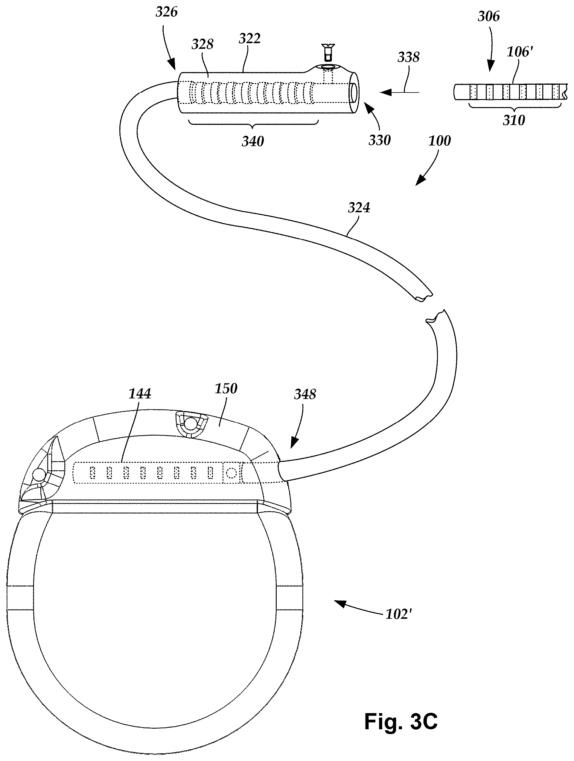
FIG. 3C is a schematic view of one embodiment of a proximal portion of the lead body of FIG. 2, a lead extension, and the control module of FIG. 2, the lead extension configured to couple the lead body to the control module, according to the invention;
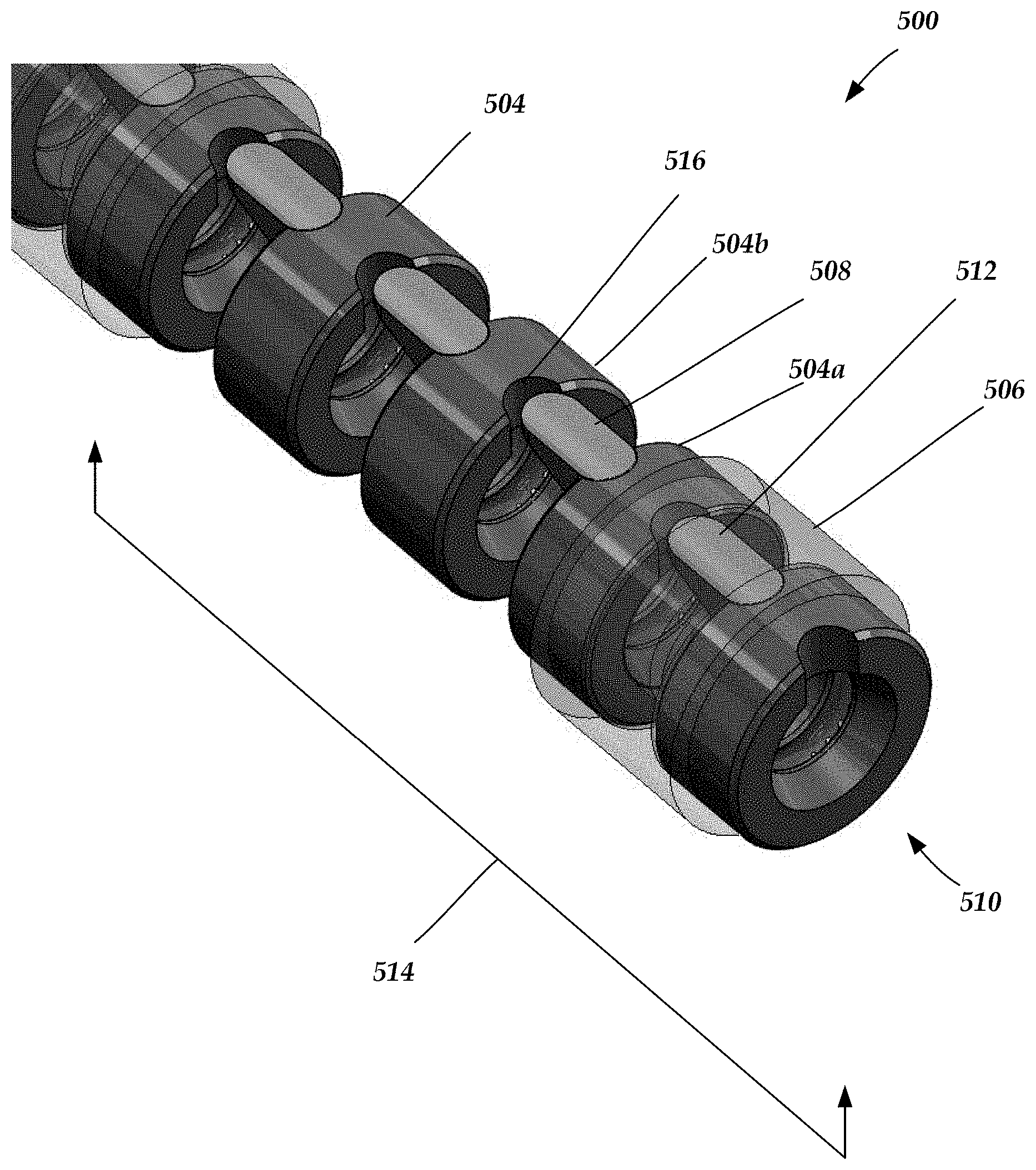
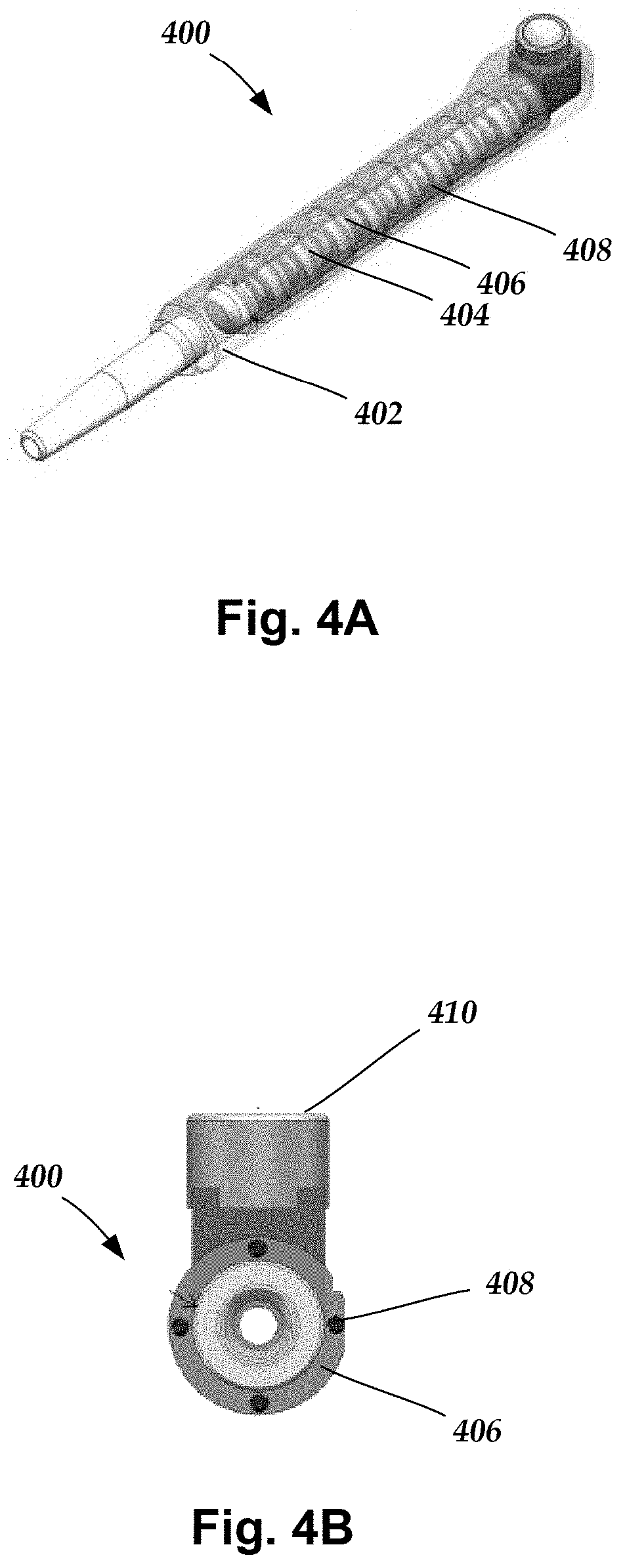
FIG. 4A is a schematic, perspective view of a connector assembly with stiffening elements according to at least some embodiments of the present invention;
FIG. 4B is a close-up view, cross-sectional view of the connector assembly of FIG. 4A;
FIG. 4C is a close-up view, perspective view of the connector housing of FIG. 4A showing the apertures for receiving the stiffening elements;
FIG. 4D is a close-up view, cross-sectional view of the connector housing of FIG. 4C;
FIG. 5 is a schematic, perspective view of a connector assembly with one set of inserts for limiting bending flexion according to at least some embodiments of the present invention;
FIG. 6 is a schematic, perspective view of a connector assembly with more than one set of inserts for limiting bending flexion according to at least some embodiments of the present invention;
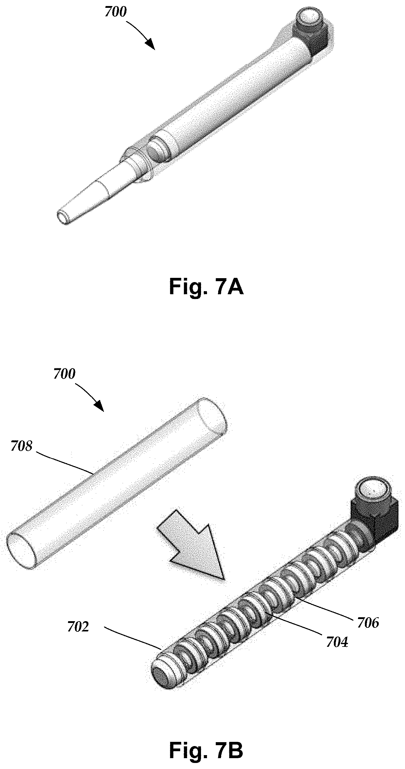
FIG. 7A is a schematic, perspective view of a connector assembly with a stiffening sleeve installed over the connector housing according to at least some embodiments of the present invention;
FIG. 7B is a schematic, perspective, exploded view of a connector assembly of FIG. 7A; and
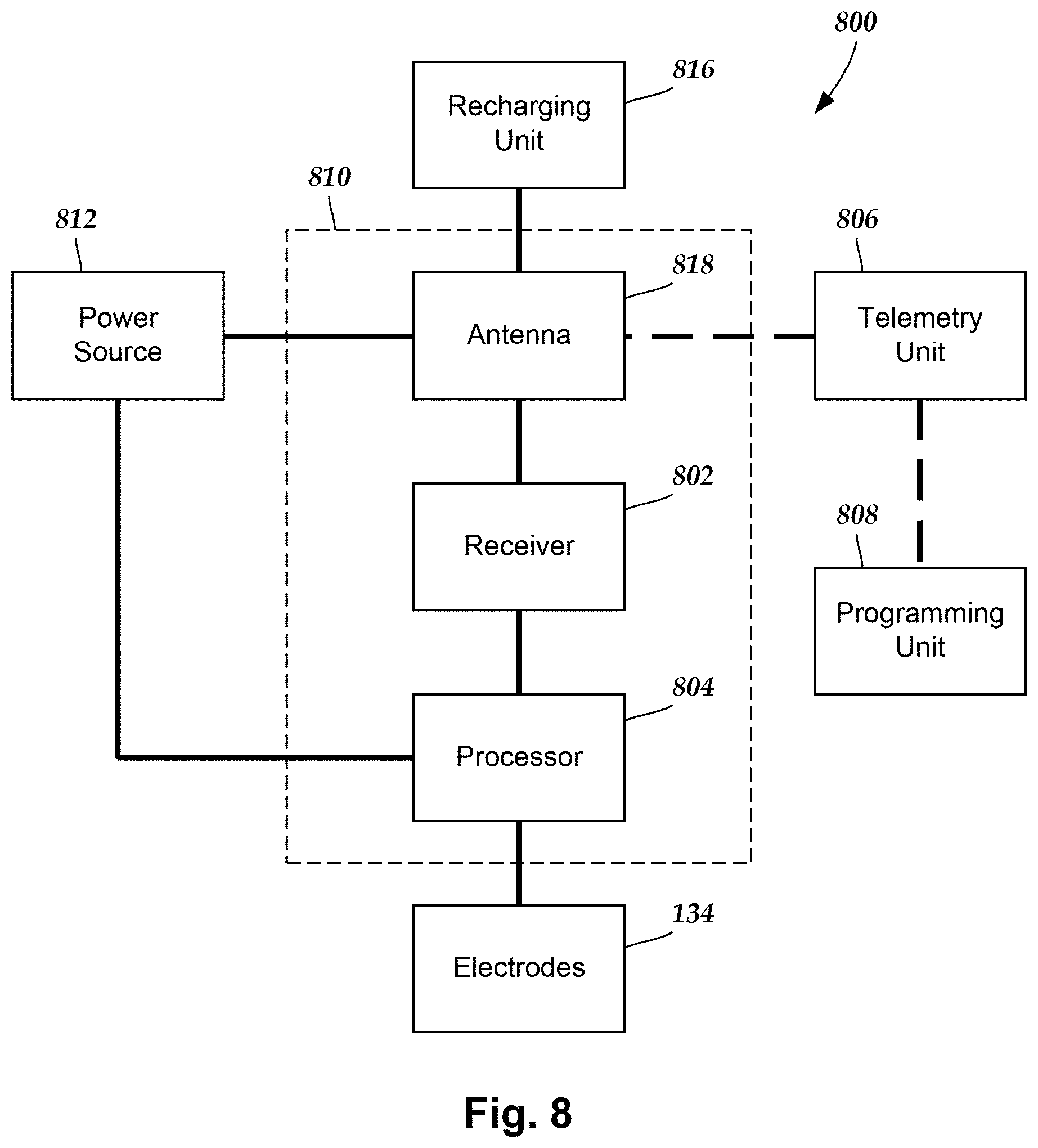
FIG. 8 is a schematic overview of one embodiment of components of a stimulation system, including an electronic subassembly disposed within a control module, according to the invention.
DETAILED DESCRIPTION
The present invention is directed to the area of implantable electrical stimulation systems and methods of making and using the systems. The present invention is also directed implantable neuromodulation lead extensions and stiffened connector assemblies that may limit bending movement of components within the connector assemblies and mitigate against a misalignment or a decoupling of electrical connections within the connector assemblies, as well as methods of making and using the same.
Suitable implantable electrical stimulation systems include, but are not limited to, a least one lead with one or more electrodes disposed along a distal end of the lead and one or more terminals disposed along the one or more proximal ends of the lead. Leads include, for example, percutaneous leads, paddle leads, and cuff leads. Examples of electrical stimulation systems with leads are found in, for example, U.S. Pat. Nos. 6,181,969; 6,295,944; 6,391,985; 6,516,227; 6,609,029; 6,609,032; 6,741,892; 7,244,150; 7,450,997; 7,672,734; 7,761,165; 7,783,359; 7,792,590; 7,809,446; 7,949,395; 7,974,706; 8,831,742; 8,688,235; 6,175,710; 6,224,450; 6,271,094; 6,295,944; 6,364,278; and 6,391,985; U.S. Patent Applications Publication Nos. 2007/0150036; 2009/0187222; 2009/0276021; 2010/0076535; 2010/0268298; 2011/0004267; 2011/0078900; 2011/0130817; 2011/0130818; 2011/0238129; 2011/0313500; 2012/0016378; 2012/0046710; 2012/0071949; 2012/0165911; 2012/0197375; 2012/0203316; 2012/0203320; 2012/0203321; 2012/0316615; 2013/0105071; 2011/0005069; 2010/0268298; 2011/0130817; 2011/0130818; 2011/0078900; 2011/0238129; 2011/0313500; 2012/0016378; 2012/0046710; 2012/0165911; 2012/0197375; 2012/0203316; 2012/0203320; and 2012/0203321, all of which are incorporated by reference in their entireties.
Examples of connectors, connector contacts and connector assemblies for electrical stimulation systems with leads are found in, for example, U.S. Pat. Nos. 8,849,396; 7,244,150; 8,600,507; 8,897,876; 8,682,439; U.S. Patent Applications Publication Nos. 2012/0053646; 2014/0148885; 2015/0209575; 2016/0059019; and U.S. Patent Provisional Patent Application Nos. 62/193,472; 62/216,594; 62/259,463; and 62/278,667, all of which are incorporated by reference in their entireties.
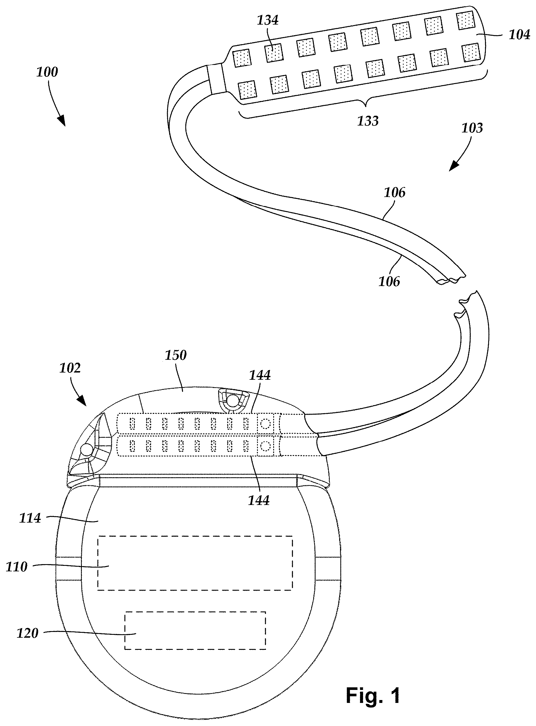
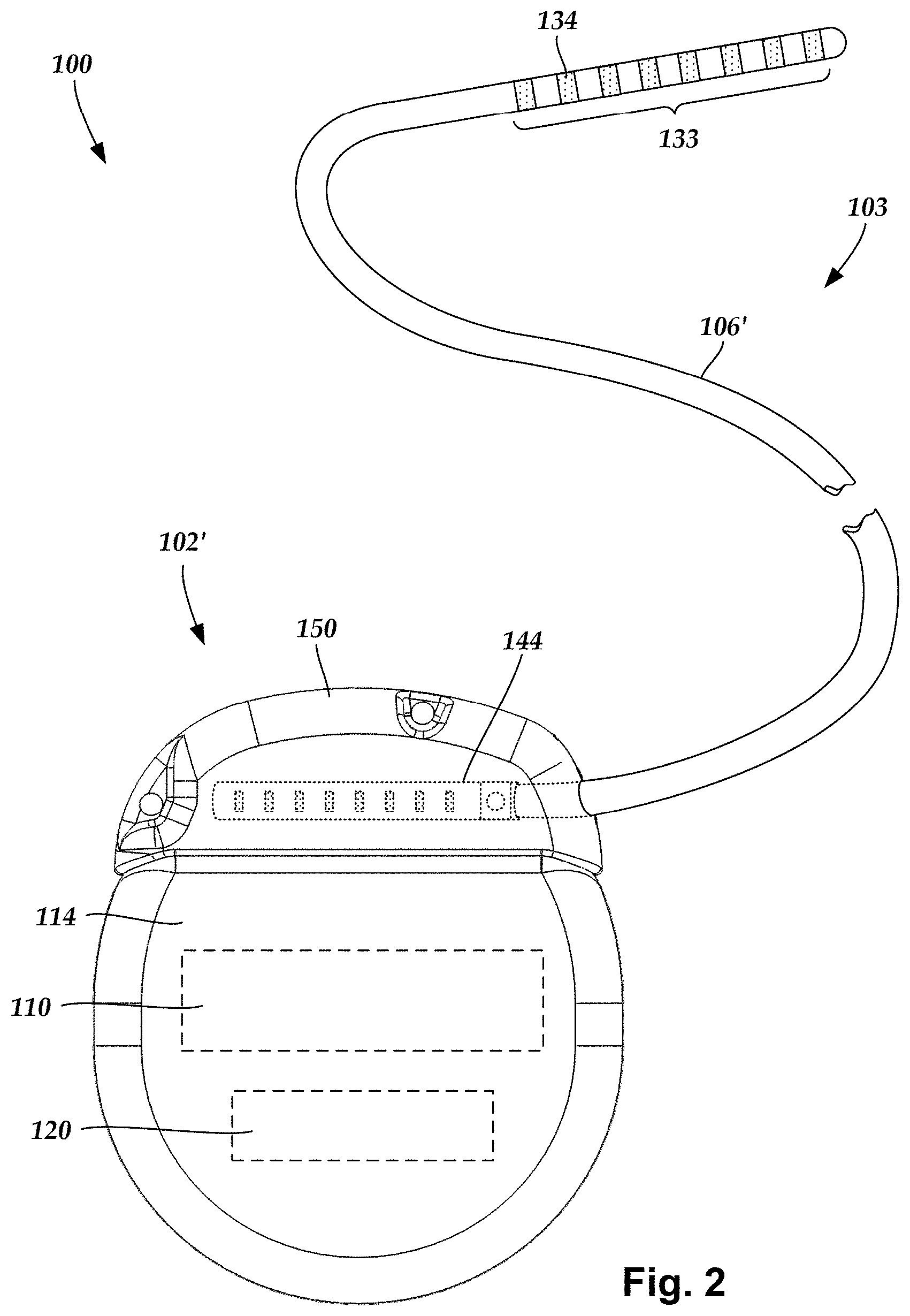
FIG. 1 illustrates schematically one embodiment of an electrical stimulation system 100. The electrical stimulation system includes a control module (e.g., a stimulator or pulse generator) 102 and a lead 103. The lead 103 including a paddle body 104 and one or more lead bodies 106 coupling the control module 102 to the paddle body 104. The paddle body 104 and the one or more lead bodies 106 form the lead 103. The paddle body 104 typically includes a plurality of electrodes 134 that form an array of electrodes 133. The control module 102 typically includes an electronic subassembly 110 and an optional power source 120 disposed in a sealed housing 114. In FIG. 1, two lead bodies 106 are shown coupled to the control module 102.
The control module 102 typically includes one or more connector assemblies 144 into which the proximal end of the one or more lead bodies 106 can be plugged to make an electrical connection via connector contacts (e.g., 316 in FIG. 3A) disposed in the connector assembly 144 and terminals (e.g., 310 in FIG. 3A) on each of the one or more lead bodies 106. The connector contacts are coupled to the electronic subassembly 110 and the terminals are coupled to the electrodes 134. In FIG. 1, two connector assemblies 144 are shown.
The one or more connector assemblies 144 may be disposed in a header 150. The header 150 provides a protective covering over the one or more connector assemblies 144. The header 150 may be formed using any suitable process including, for example, casting, molding (including injection molding), and the like. In addition, one or more lead extensions 324 (see FIG. 3C) can be disposed between the one or more lead bodies 106 and the control module 102 to extend the distance between the one or more lead bodies 106 and the control module 102.
It will be understood that the electrical stimulation system can include more, fewer, or different components and can have a variety of different configurations including those configurations disclosed in the electrical stimulation system references cited herein. For example, instead of a paddle body 104, the electrodes 134 can be disposed in an array at or near the distal end of a lead body 106' forming a percutaneous lead 103, as illustrated in FIG. 2. The percutaneous lead may be isodiametric along the length of the lead body 106''. The lead body 106' can be coupled with a control module 102' with a single connector assembly 144.
The electrical stimulation system or components of the electrical stimulation system, including one or more of the lead bodies 106, the control module 102, and, in the case of a paddle lead, the paddle body 104, are typically implanted into the body of a patient. The electrical stimulation system can be used for a variety of applications including, but not limited to, spinal cord stimulation, brain stimulation, neural stimulation, muscle activation via stimulation of nerves innervating muscle, and the like.
The electrodes 134 can be formed using any conductive, biocompatible material. Examples of suitable materials include metals, alloys, conductive polymers, conductive carbon, and the like, as well as combinations thereof. In at least some embodiments, one or more of the electrodes 134 are formed from one or more of: platinum, platinum iridium, palladium, titanium, or rhenium.
The number of electrodes 134 in the array of electrodes 133 may vary. For example, there can be two, three, four, five, six, seven, eight, nine, ten, eleven, twelve, thirteen, fourteen, fifteen, sixteen, or more electrodes 134. As will be recognized, other numbers of electrodes 134 may also be used. In FIG. 1, sixteen electrodes 134 are shown. The electrodes 134 can be formed in any suitable shape including, for example, round, oval, triangular, rectangular, pentagonal, hexagonal, heptagonal, octagonal, or the like.
The electrodes of the paddle body 104 or one or more lead bodies 106 are typically disposed in, or separated by, a non-conductive, biocompatible material including, for example, silicone, polyurethane, and the like or combinations thereof. The paddle body 104 and one or more lead bodies 106 may be formed in the desired shape by any process including, for example, molding (including injection molding), casting, and the like. Electrodes and connecting wires can be disposed onto or within a paddle body either prior to or subsequent to a molding or casting process. The non-conductive material typically extends from the distal end of the lead 103 to the proximal end of each of the one or more lead bodies 106. The non-conductive, biocompatible material of the paddle body 104 and the one or more lead bodies 106 may be the same or different. The paddle body 104 and the one or more lead bodies 106 may be a unitary structure or can be formed as two separate structures that are permanently or detachably coupled together.
Terminals (e.g., 310 in FIG. 3A) are typically disposed at the proximal end of the one or more lead bodies 106 for connection to corresponding conductive contacts (e.g., 316 in FIG. 3A) in connector assemblies (e.g., 144 in FIG. 1) disposed on, for example, the control module 102 (or to other devices, such as conductive contacts on a lead extension, an operating room cable, a splitter, an adaptor, or the like).
Conductive wires (not shown) extend from the terminals (e.g., 310 in FIG. 3A) to the electrodes 134. Typically, one or more electrodes 134 are electrically coupled to a terminal (e.g., 310 in FIG. 3A). In some embodiments, each terminal (e.g., 310 in FIG. 3A) is only coupled to one electrode 134.
The conductive wires may be embedded in the non-conductive material of the lead or can be disposed in one or more lumens (not shown) extending along the lead. In some embodiments, there is an individual lumen for each conducti
D00000
D00001
D00002
D00003
D00004
D00005
D00006
D00007
D00008
D00009
D00010
XML
uspto.report is an independent third-party trademark research tool that is not affiliated, endorsed, or sponsored by the United States Patent and Trademark Office (USPTO) or any other governmental organization. The information provided by uspto.report is based on publicly available data at the time of writing and is intended for informational purposes only.
While we strive to provide accurate and up-to-date information, we do not guarantee the accuracy, completeness, reliability, or suitability of the information displayed on this site. The use of this site is at your own risk. Any reliance you place on such information is therefore strictly at your own risk.
All official trademark data, including owner information, should be verified by visiting the official USPTO website at www.uspto.gov. This site is not intended to replace professional legal advice and should not be used as a substitute for consulting with a legal professional who is knowledgeable about trademark law.