Surgical clip applier and method of assembly
Zergiebel Ja
U.S. patent number 10,542,999 [Application Number 15/375,212] was granted by the patent office on 2020-01-28 for surgical clip applier and method of assembly. This patent grant is currently assigned to COVIDIEN LP. The grantee listed for this patent is Covidien LP. Invention is credited to Earl M. Zergiebel.


View All Diagrams
| United States Patent | 10,542,999 |
| Zergiebel | January 28, 2020 |
Surgical clip applier and method of assembly
Abstract
Surgical clip appliers are provided and includes a channel assembly extending distally from a housing; a clip carrier disposed within said channel assembly and defining a channel and a plurality of windows therein; a plurality of clips slidably disposed within said channel of said clip carrier; a wedge plate reciprocally disposed within said channel assembly, said wedge plate being operatively connected to said handles and including a plurality of apertures formed along a length thereof; and a clip follower slidably disposed within said channel of said clip carrier and disposed proximally of said plurality of clips, said clip follower being configured and adapted for selective engagement with said windows of said clip carrier and said apertures of said wedge plate. The clip follower is configured and adapted to urge said plurality of clips, in a distal direction relative to said clip carrier, upon reciprocal movement of said wedge plate.
| Inventors: | Zergiebel; Earl M. (Guilford, CT) | ||||||||||
|---|---|---|---|---|---|---|---|---|---|---|---|
| Applicant: |
|
||||||||||
| Assignee: | COVIDIEN LP (Mansfield,
MA) |
||||||||||
| Family ID: | 41268479 | ||||||||||
| Appl. No.: | 15/375,212 | ||||||||||
| Filed: | December 12, 2016 |
Prior Publication Data
| Document Identifier | Publication Date | |
|---|---|---|
| US 20170086850 A1 | Mar 30, 2017 | |
Related U.S. Patent Documents
| Application Number | Filing Date | Patent Number | Issue Date | ||
|---|---|---|---|---|---|
| 13890580 | May 9, 2013 | 9549741 | |||
| 12540475 | Jun 18, 2013 | 8465502 | |||
| 61091467 | Aug 25, 2008 | ||||
| Current U.S. Class: | 1/1 |
| Current CPC Class: | A61B 17/083 (20130101); A61B 17/12 (20130101); A61B 17/105 (20130101); A61B 17/1285 (20130101); A61B 17/1222 (20130101); A61B 17/128 (20130101); A61B 2090/038 (20160201); A61B 2017/00407 (20130101) |
| Current International Class: | A61B 17/12 (20060101); A61B 17/128 (20060101); A61B 17/08 (20060101); A61B 17/10 (20060101); A61B 17/122 (20060101); A61B 90/00 (20160101) |
References Cited [Referenced By]
U.S. Patent Documents
| 3120230 | February 1964 | Skold |
| 3363628 | January 1968 | Wood |
| 3638847 | February 1972 | Noiles et al. |
| 3675688 | July 1972 | Bryan et al. |
| 3867944 | February 1975 | Samuels |
| 4242902 | January 1981 | Green |
| 4296751 | October 1981 | Blake, III et al. |
| 4372316 | February 1983 | Blake, III et al. |
| 4408603 | October 1983 | Blake, III et al. |
| 4412539 | November 1983 | Jarvik |
| 4418694 | December 1983 | Beroff et al. |
| 4471780 | September 1984 | Menges et al. |
| 4480640 | November 1984 | Becht |
| 4480641 | November 1984 | Failla et al. |
| 4487204 | December 1984 | Hrouda |
| 4487205 | December 1984 | Di Giovanni et al. |
| 4491133 | January 1985 | Menges et al. |
| 4492232 | January 1985 | Green |
| 4498476 | February 1985 | Cerwin et al. |
| 4500024 | February 1985 | DiGiovanni et al. |
| 4509518 | April 1985 | McGarry et al. |
| 4512345 | April 1985 | Green |
| 4522207 | June 1985 | Klieman et al. |
| 4532925 | August 1985 | Blake, III |
| 4534351 | August 1985 | Rothfuss et al. |
| 4545377 | October 1985 | Cerwin et al. |
| 4549544 | October 1985 | Favaron |
| 4556058 | December 1985 | Green |
| 4557263 | December 1985 | Green |
| 4562839 | January 1986 | Blake, III et al. |
| 4572183 | February 1986 | Juska |
| 4576165 | March 1986 | Green et al. |
| 4576166 | March 1986 | Montgomery et al. |
| 4590937 | May 1986 | Deniega |
| 4598711 | July 1986 | Deniega |
| 4602631 | July 1986 | Funatsu |
| 4611595 | September 1986 | Klieman et al. |
| 4612932 | September 1986 | Caspar et al. |
| 4616650 | October 1986 | Green et al. |
| 4616651 | October 1986 | Golden |
| 4624254 | November 1986 | McGarry et al. |
| 4637395 | January 1987 | Caspar et al. |
| 4646740 | March 1987 | Peters et al. |
| 4647504 | March 1987 | Kimimura et al. |
| 4658822 | April 1987 | Kees, Jr. |
| 4660558 | April 1987 | Kees, Jr. |
| 4662373 | May 1987 | Montgomery et al. |
| 4662374 | May 1987 | Blake, III |
| 4671278 | June 1987 | Chin |
| 4671282 | June 1987 | Tretbar |
| 4674504 | June 1987 | Klieman et al. |
| 4681107 | July 1987 | Kees, Jr. |
| 4696396 | September 1987 | Samuels |
| 4702247 | October 1987 | Blake, III et al. |
| 4706668 | November 1987 | Backer |
| 4712549 | December 1987 | Peters et al. |
| 4733664 | March 1988 | Kirsch et al. |
| 4733666 | March 1988 | Mercer, Jr. |
| 4759364 | July 1988 | Boebel |
| 4765335 | August 1988 | Schmidt et al. |
| 4777949 | October 1988 | Perlin |
| 4777950 | October 1988 | Kees, Jr. |
| 4796625 | January 1989 | Kees, Jr. |
| 4799481 | January 1989 | Transue et al. |
| 4815466 | March 1989 | Perlin |
| 4817604 | April 1989 | Smith, III |
| 4821721 | April 1989 | Chin et al. |
| 4822348 | April 1989 | Casey |
| 4827930 | May 1989 | Kees, Jr. |
| 4834096 | May 1989 | Oh et al. |
| 4850355 | July 1989 | Brooks et al. |
| 4854317 | August 1989 | Braun |
| 4856517 | August 1989 | Collins et al. |
| 4929239 | May 1990 | Braun |
| 4929240 | May 1990 | Kirsch et al. |
| 4931058 | June 1990 | Cooper |
| 4932955 | June 1990 | Merz et al. |
| 4934364 | June 1990 | Green |
| 4943298 | July 1990 | Fujita et al. |
| 4957500 | September 1990 | Liang et al. |
| 4966603 | October 1990 | Focelle et al. |
| 4967949 | November 1990 | Sandhaus |
| 4983176 | January 1991 | Cushman et al. |
| 4988355 | January 1991 | Leveen et al. |
| 5002552 | March 1991 | Casey |
| 5026379 | June 1991 | Yoon |
| 5030224 | July 1991 | Wright et al. |
| 5030226 | July 1991 | Green et al. |
| 5032127 | July 1991 | Frazee et al. |
| 5035692 | July 1991 | Lyon et al. |
| 5047038 | September 1991 | Peters et al. |
| 5049152 | September 1991 | Simon et al. |
| 5049153 | September 1991 | Nakao et al. |
| 5053045 | October 1991 | Schmidt et al. |
| 5059202 | October 1991 | Liang et al. |
| 5062846 | November 1991 | Oh et al. |
| 5078731 | January 1992 | Hayhurst |
| 5084057 | January 1992 | Green et al. |
| 5100416 | March 1992 | Oh et al. |
| 5100420 | March 1992 | Green et al. |
| 5104394 | April 1992 | Knoepfler |
| 5104395 | April 1992 | Thornton et al. |
| 5112343 | May 1992 | Thornton |
| 5122150 | June 1992 | Puig |
| 5127915 | July 1992 | Mattson |
| 5129885 | July 1992 | Green et al. |
| 5156608 | October 1992 | Troidl et al. |
| 5160339 | November 1992 | Chen et al. |
| 5163945 | November 1992 | Ortiz et al. |
| 5171247 | December 1992 | Hughett et al. |
| 5171249 | December 1992 | Stefanchik et al. |
| 5171250 | December 1992 | Yoon |
| 5171251 | December 1992 | Bregen et al. |
| 5171252 | December 1992 | Friedland |
| 5171253 | December 1992 | Klieman |
| 5192288 | March 1993 | Thompson et al. |
| 5197970 | March 1993 | Green et al. |
| 5199566 | April 1993 | Ortiz et al. |
| 5201746 | April 1993 | Shichman |
| 5201900 | April 1993 | Nardella |
| 5207691 | May 1993 | Nardella |
| 5207692 | May 1993 | Kraus et al. |
| 5217473 | June 1993 | Yoon |
| 5219353 | June 1993 | Garvey, III et al. |
| 5246450 | September 1993 | Thornton et al. |
| 5269792 | December 1993 | Kovac et al. |
| 5281228 | January 1994 | Wolfson |
| 5282807 | February 1994 | Knoepfler |
| 5282808 | February 1994 | Kovac et al. |
| 5282832 | February 1994 | Toso et al. |
| 5289963 | March 1994 | McGarry et al. |
| 5290299 | March 1994 | Fain et al. |
| 5300081 | April 1994 | Young et al. |
| 5304183 | April 1994 | Gourlay et al. |
| 5306280 | April 1994 | Bregen et al. |
| 5306283 | April 1994 | Conners |
| 5312426 | May 1994 | Segawa et al. |
| 5330442 | July 1994 | Green et al. |
| 5330487 | July 1994 | Thornton et al. |
| 5340360 | August 1994 | Stefanchik |
| 5342373 | August 1994 | Stefanchik et al. |
| 5354304 | October 1994 | Allen et al. |
| 5354306 | October 1994 | Garvey, III et al. |
| 5366458 | November 1994 | Korthoff et al. |
| 5366459 | November 1994 | Yoon |
| 5368600 | November 1994 | Failla et al. |
| 5381943 | January 1995 | Allen et al. |
| 5382253 | January 1995 | Hogendijk |
| 5382254 | January 1995 | McGarry et al. |
| 5382255 | January 1995 | Castro et al. |
| 5383880 | January 1995 | Hooven |
| 5383881 | January 1995 | Green et al. |
| 5395375 | March 1995 | Turkel et al. |
| 5395381 | March 1995 | Green et al. |
| 5403327 | April 1995 | Thornton et al. |
| 5409498 | April 1995 | Braddock et al. |
| 5413584 | May 1995 | Schulze |
| 5423835 | June 1995 | Green et al. |
| 5425740 | June 1995 | Hutchinson, Jr. |
| 5431667 | July 1995 | Thompson et al. |
| 5431668 | July 1995 | Burbank, III et al. |
| 5431669 | July 1995 | Thompson et al. |
| 5439468 | August 1995 | Schulze et al. |
| 5441509 | August 1995 | Vidal et al. |
| 5447513 | September 1995 | Davison et al. |
| 5449365 | September 1995 | Green et al. |
| 5462555 | October 1995 | Bolanos et al. |
| 5462558 | October 1995 | Kolesa et al. |
| 5464416 | November 1995 | Steckel |
| 5474566 | December 1995 | Alesi et al. |
| 5474567 | December 1995 | Stefanchik et al. |
| 5474572 | December 1995 | Hayhurst |
| 5487746 | January 1996 | Yu et al. |
| 5501693 | March 1996 | Gravener |
| 5509920 | April 1996 | Phillips et al. |
| 5514149 | May 1996 | Green et al. |
| 5520701 | May 1996 | Lerch |
| 5522823 | June 1996 | Kuntz et al. |
| 5527318 | June 1996 | McGarry |
| 5527319 | June 1996 | Green et al. |
| 5527320 | June 1996 | Carruthers et al. |
| 5542949 | August 1996 | Yoon |
| 5547474 | August 1996 | Kloeckl et al. |
| 5569274 | October 1996 | Rapacki et al. |
| 5571121 | November 1996 | Heifetz |
| 5575802 | November 1996 | McQuilkin et al. |
| 5582615 | December 1996 | Foshee et al. |
| 5584840 | December 1996 | Ramsey et al. |
| 5591178 | January 1997 | Green et al. |
| 5593414 | January 1997 | Shipp et al. |
| 5593421 | January 1997 | Bauer |
| 5601573 | February 1997 | Fogelberg et al. |
| 5601574 | February 1997 | Stefanchik et al. |
| 5607436 | March 1997 | Pratt et al. |
| 5618291 | April 1997 | Thompson et al. |
| 5618306 | April 1997 | Roth et al. |
| 5620452 | April 1997 | Yoon |
| 5626585 | May 1997 | Mittelstadt et al. |
| 5626586 | May 1997 | Pistl et al. |
| 5626587 | May 1997 | Bishop et al. |
| 5626592 | May 1997 | Phillips et al. |
| RE35525 | June 1997 | Stefanchik et al. |
| 5634930 | June 1997 | Thornton et al. |
| 5643291 | July 1997 | Pier et al. |
| 5645551 | July 1997 | Green et al. |
| 5645553 | July 1997 | Kolesa et al. |
| 5649937 | July 1997 | Bito et al. |
| 5653720 | August 1997 | Johnson et al. |
| 5662676 | September 1997 | Koninckx |
| 5662679 | September 1997 | Voss et al. |
| 5665097 | September 1997 | Baker et al. |
| 5676676 | October 1997 | Porter |
| 5681330 | October 1997 | Hughett et al. |
| 5683405 | November 1997 | Yacoubian et al. |
| 5695502 | December 1997 | Pier et al. |
| 5695505 | December 1997 | Yoon |
| 5697938 | December 1997 | Jensen et al. |
| 5697942 | December 1997 | Palti |
| 5700270 | December 1997 | Peyser et al. |
| 5700271 | December 1997 | Whitfield et al. |
| 5702048 | December 1997 | Eberlin |
| 5709706 | January 1998 | Kienzle et al. |
| 5713911 | February 1998 | Racenet et al. |
| 5713912 | February 1998 | Porter |
| 5720756 | February 1998 | Green et al. |
| 5722982 | March 1998 | Ferreira et al. |
| 5725537 | March 1998 | Green et al. |
| 5725538 | March 1998 | Green et al. |
| 5725542 | March 1998 | Yoon |
| 5733295 | March 1998 | Back et al. |
| 5755726 | May 1998 | Pratt et al. |
| 5766189 | June 1998 | Matsuno |
| 5769857 | June 1998 | Reztzov et al. |
| 5772673 | June 1998 | Cuny et al. |
| 5776146 | July 1998 | Sackier et al. |
| 5776147 | July 1998 | Dolendo |
| 5779718 | July 1998 | Green et al. |
| 5779720 | July 1998 | Walder-Utz et al. |
| 5782844 | July 1998 | Yoon et al. |
| 5788698 | August 1998 | Savornin |
| 5792149 | August 1998 | Sherts et al. |
| 5792150 | August 1998 | Pratt et al. |
| 5797922 | August 1998 | Hessel et al. |
| 5810853 | September 1998 | Yoon |
| 5817116 | October 1998 | Takahashi et al. |
| 5827306 | October 1998 | Yoon |
| 5827323 | October 1998 | Klieman et al. |
| 5833695 | November 1998 | Yoon |
| 5833696 | November 1998 | Whitfield et al. |
| 5833700 | November 1998 | Fogelberg et al. |
| 5835199 | November 1998 | Phillips et al. |
| 5843097 | December 1998 | Mayenberger et al. |
| 5843101 | December 1998 | Fry |
| 5846255 | December 1998 | Casey |
| 5849019 | December 1998 | Yoon |
| 5858018 | January 1999 | Shipp et al. |
| 5861005 | January 1999 | Kontos |
| 5868759 | February 1999 | Peyser et al. |
| 5868761 | February 1999 | Nicholas et al. |
| 5876410 | March 1999 | Petillo |
| 5895394 | April 1999 | Kienzle et al. |
| 5897565 | April 1999 | Foster |
| 5904693 | May 1999 | Dicesare et al. |
| 5906625 | May 1999 | Bito et al. |
| 5913862 | June 1999 | Ramsey et al. |
| 5913876 | June 1999 | Taylor et al. |
| 5918791 | July 1999 | Sorrentino et al. |
| 5921996 | July 1999 | Sherman |
| 5921997 | July 1999 | Fogelberg et al. |
| 5928251 | July 1999 | Aranyi et al. |
| 5938667 | August 1999 | Peyser et al. |
| 5951574 | September 1999 | Stefanchik et al. |
| 5972003 | October 1999 | Rousseau et al. |
| 5976159 | November 1999 | Bolduc et al. |
| 5993465 | November 1999 | Shipp et al. |
| 6004335 | December 1999 | Vaitekunas et al. |
| 6017358 | January 2000 | Yoon et al. |
| 6045560 | April 2000 | McKean et al. |
| 6053908 | April 2000 | Crainich et al. |
| RE36720 | May 2000 | Green et al. |
| 6059799 | May 2000 | Aranyi et al. |
| 6099536 | August 2000 | Petillo |
| 6099537 | August 2000 | Sugai et al. |
| 6139555 | October 2000 | Hart et al. |
| 6210418 | April 2001 | Storz et al. |
| 6217590 | April 2001 | Levinson |
| 6228097 | May 2001 | Levinson et al. |
| 6241740 | June 2001 | Davis et al. |
| 6258105 | July 2001 | Hart et al. |
| 6261302 | July 2001 | Voegele et al. |
| 6273898 | August 2001 | Kienzle et al. |
| 6277131 | August 2001 | Kalikow |
| 6306149 | October 2001 | Meade |
| 6318619 | November 2001 | Lee |
| 6322571 | November 2001 | Adams |
| 6350269 | February 2002 | Shipp et al. |
| 6352541 | March 2002 | Kienzle et al. |
| 6391035 | May 2002 | Appleby et al. |
| 6423079 | July 2002 | Blake, III |
| 6428548 | August 2002 | Durgin et al. |
| 6440144 | August 2002 | Bacher |
| 6461363 | October 2002 | Gadberry et al. |
| 6464710 | October 2002 | Foster |
| 6494886 | December 2002 | Wilk et al. |
| 6517536 | February 2003 | Hooven et al. |
| 6520972 | February 2003 | Peters |
| 6527786 | March 2003 | Davis et al. |
| 6537289 | March 2003 | Kayan et al. |
| 6546935 | April 2003 | Hooven |
| 6551333 | April 2003 | Kuhns et al. |
| 6562051 | May 2003 | Bolduc et al. |
| 6569171 | May 2003 | DeGuillebon et al. |
| 6579304 | June 2003 | Hart et al. |
| 6599298 | July 2003 | Forster et al. |
| 6602252 | August 2003 | Mollenauer |
| 6607540 | August 2003 | Shipp |
| 6613060 | September 2003 | Adams et al. |
| 6626916 | September 2003 | Yeung et al. |
| 6626922 | September 2003 | Hart et al. |
| 6648898 | November 2003 | Baxter |
| 6652538 | November 2003 | Kayan et al. |
| 6652539 | November 2003 | Shipp et al. |
| 6656193 | December 2003 | Grant et al. |
| 6673083 | January 2004 | Kayan et al. |
| 6676659 | January 2004 | Hutchins et al. |
| 6679894 | January 2004 | Damarati |
| RE38445 | February 2004 | Pistl et al. |
| 6695854 | February 2004 | Kayan et al. |
| 6706057 | March 2004 | Bidoia et al. |
| 6716226 | April 2004 | Sixto, Jr. et al. |
| 6723109 | April 2004 | Solingen |
| 6743240 | June 2004 | Smith et al. |
| 6773438 | August 2004 | Knodel et al. |
| 6773440 | August 2004 | Gannoe et al. |
| 6776783 | August 2004 | Frantzen et al. |
| 6776784 | August 2004 | Ginn |
| 6780195 | August 2004 | Porat |
| 6793663 | September 2004 | Kneifel et al. |
| 6793664 | September 2004 | Mazzocchi et al. |
| 6802848 | October 2004 | Anderson et al. |
| 6814742 | November 2004 | Kimura et al. |
| 6818009 | November 2004 | Hart et al. |
| 6821273 | November 2004 | Mollenauer |
| 6821284 | November 2004 | Sturtz et al. |
| 6824547 | November 2004 | Wilson, Jr. et al. |
| 6824548 | November 2004 | Smith et al. |
| 6835199 | December 2004 | McGuckin, Jr. et al. |
| 6835200 | December 2004 | Laufer et al. |
| 6837893 | January 2005 | Miller |
| 6837894 | January 2005 | Pugsley, Jr. et al. |
| 6837895 | January 2005 | Mayenberger |
| 6840945 | January 2005 | Manetakis et al. |
| 6843794 | January 2005 | Sixto, Jr. et al. |
| 6849078 | February 2005 | Durgin et al. |
| 6849079 | February 2005 | Blake, III et al. |
| 6853879 | February 2005 | Sunaoshi |
| 6869435 | March 2005 | Blake, III |
| 6869436 | March 2005 | Wendlandt |
| 6889116 | May 2005 | Jinno |
| 6896682 | May 2005 | McClellan et al. |
| 6905503 | June 2005 | Gifford, III et al. |
| 6911032 | June 2005 | Jugenheimer et al. |
| 6911033 | June 2005 | de Guillebon et al. |
| 6913607 | July 2005 | Ainsworth et al. |
| 6916327 | July 2005 | Northrup, III et al. |
| 6923818 | August 2005 | Muramatsu et al. |
| 6939356 | September 2005 | Debbas |
| 6942674 | September 2005 | Belef et al. |
| 6942676 | September 2005 | Buelna |
| 6945978 | September 2005 | Hyde |
| 6945979 | September 2005 | Kortenbach et al. |
| 6949107 | September 2005 | McGuckin, Jr. et al. |
| 6953465 | October 2005 | Dieck et al. |
| 6955643 | October 2005 | Gellman et al. |
| 6959852 | November 2005 | Shelton, IV et al. |
| 6960218 | November 2005 | Rennich |
| 6960221 | November 2005 | Ho et al. |
| 6962594 | November 2005 | Thevenet |
| 6963792 | November 2005 | Green |
| 6964363 | November 2005 | Wales et al. |
| 6964668 | November 2005 | Modesitt et al. |
| 6966875 | November 2005 | Longobardi |
| 6966917 | November 2005 | Suyker et al. |
| 6966919 | November 2005 | Sixto, Jr. et al. |
| 6969391 | November 2005 | Gazzani |
| 6972023 | December 2005 | Whayne et al. |
| 6972027 | December 2005 | Fallin et al. |
| 6973770 | December 2005 | Schnipke et al. |
| 6974462 | December 2005 | Sater |
| 6974466 | December 2005 | Ahmed et al. |
| 6974475 | December 2005 | Wall |
| 6981505 | January 2006 | Krause et al. |
| 6981628 | January 2006 | Wales |
| 6991635 | January 2006 | Takamoto et al. |
| 7052504 | May 2006 | Hughett |
| 7056330 | June 2006 | Gayton |
| 7108703 | September 2006 | Danitz et al. |
| 7144402 | December 2006 | Kuester, III |
| 7175648 | February 2007 | Nakao |
| 7179265 | February 2007 | Manetakis et al. |
| 7207997 | April 2007 | Shipp et al. |
| 7211091 | May 2007 | Fowler et al. |
| 7211092 | May 2007 | Hughett |
| 7214230 | May 2007 | Brock et al. |
| 7214232 | May 2007 | Bowman et al. |
| 7223271 | May 2007 | Muramatsu et al. |
| 7223272 | May 2007 | Francese et al. |
| 7232445 | June 2007 | Kortenbach et al. |
| 7261724 | August 2007 | Molitor et al. |
| 7261725 | August 2007 | Binmoeller |
| 7264625 | September 2007 | Buncke |
| 7288098 | October 2007 | Huitema et al. |
| 7297149 | November 2007 | Vitali et al. |
| 7316693 | January 2008 | Viola |
| 7316696 | January 2008 | Wilson, Jr. et al. |
| 7326223 | February 2008 | Wilson, Jr. |
| 7329266 | February 2008 | Royse et al. |
| 7331968 | February 2008 | Arp et al. |
| 7338503 | March 2008 | Rosenberg et al. |
| 7357805 | April 2008 | Masuda et al. |
| 7510562 | March 2009 | Lindsay |
| 7552853 | June 2009 | Mas et al. |
| 7637917 | December 2009 | Whitfield et al. |
| 7686820 | March 2010 | Huitema et al. |
| 7695482 | April 2010 | Viola |
| 7717926 | May 2010 | Whitfield et al. |
| 7727248 | June 2010 | Smith et al. |
| 7731724 | June 2010 | Huitema et al. |
| 7740641 | June 2010 | Huitema |
| 7752853 | July 2010 | Singh et al. |
| 7753250 | July 2010 | Clauson et al. |
| 7819886 | October 2010 | Whitfield et al. |
| 7887553 | February 2011 | Lehman et al. |
| 7905890 | March 2011 | Whitfield et al. |
| 7942885 | May 2011 | Sixto, Jr. et al. |
| 7963433 | June 2011 | Whitman et al. |
| 8021375 | September 2011 | Aldrich et al. |
| 8038686 | October 2011 | Huitema et al. |
| 8056565 | November 2011 | Zergiebel |
| 8062310 | November 2011 | Shibata et al. |
| 8066720 | November 2011 | Knodel et al. |
| 8066721 | November 2011 | Kortenbach et al. |
| 8066722 | November 2011 | Miyagi et al. |
| 8075571 | December 2011 | Vitali et al. |
| 8080021 | December 2011 | Griego |
| 8091755 | January 2012 | Kayan et al. |
| 8100926 | January 2012 | Filshie et al. |
| 8128643 | March 2012 | Aranyi et al. |
| 8133240 | March 2012 | Damarati |
| 8172859 | May 2012 | Matsuno et al. |
| 8172870 | May 2012 | Shipp |
| 8187290 | May 2012 | Buckman et al. |
| 8211120 | July 2012 | Itoh |
| 8211124 | July 2012 | Ainsworth et al. |
| 8216255 | July 2012 | Smith et al. |
| 8262678 | September 2012 | Matsuoka et al. |
| 8272554 | September 2012 | Whitman et al. |
| 8308743 | November 2012 | Matsuno et al. |
| 8366709 | February 2013 | Schechter et al. |
| 8366726 | February 2013 | Dennis |
| 8372095 | February 2013 | Viola |
| 8398655 | March 2013 | Cheng et al. |
| 8403945 | March 2013 | Whitfield et al. |
| 8403946 | March 2013 | Whitfield et al. |
| 8408442 | April 2013 | Racenet et al. |
| 8419752 | April 2013 | Sorrentino et al. |
| 8430892 | April 2013 | Bindra et al. |
| 8465460 | June 2013 | Yodfat et al. |
| 8465502 | June 2013 | Zergiebel |
| 8506580 | August 2013 | Zergiebel et al. |
| 8545486 | October 2013 | Malkowski |
| 8556920 | October 2013 | Huitema et al. |
| 8568430 | October 2013 | Shipp |
| 8585717 | November 2013 | Sorrentino et al. |
| 8603109 | December 2013 | Aranyi et al. |
| 8652151 | February 2014 | Lehman et al. |
| 8652152 | February 2014 | Aranyi et al. |
| 8663247 | March 2014 | Menn et al. |
| 8685048 | April 2014 | Adams et al. |
| 8690899 | April 2014 | Kogiso et al. |
| 8708213 | April 2014 | Shelton, IV et al. |
| 8709027 | April 2014 | Adams et al. |
| 8720766 | May 2014 | Hess et al. |
| 8734469 | May 2014 | Pribanic et al. |
| 8747423 | June 2014 | Whitfield et al. |
| 8753356 | June 2014 | Vitali et al. |
| 8814884 | August 2014 | Whitfield et al. |
| 8821516 | September 2014 | Huitema |
| 8839954 | September 2014 | Disch |
| 8845659 | September 2014 | Whitfield et al. |
| 8894665 | November 2014 | Sorrentino et al. |
| 8894666 | November 2014 | Schulz et al. |
| 8900253 | December 2014 | Aranyi et al. |
| 8920438 | December 2014 | Aranyi et al. |
| 8939974 | January 2015 | Boudreaux et al. |
| 8950646 | February 2015 | Viola |
| 8961542 | February 2015 | Whitfield et al. |
| 8968337 | March 2015 | Whitfield et al. |
| 8968342 | March 2015 | Wingardner, III et al. |
| 8973804 | March 2015 | Hess et al. |
| 9011464 | April 2015 | Zammataro |
| 9011465 | April 2015 | Whitfield et al. |
| 9089334 | July 2015 | Sorrentino et al. |
| 9113892 | August 2015 | Malkowski et al. |
| 9113893 | August 2015 | Sorrentino et al. |
| 9186136 | November 2015 | Malkowski et al. |
| 9186153 | November 2015 | Zammataro |
| 9220507 | December 2015 | Patel et al. |
| 9358011 | June 2016 | Sorrentino et al. |
| 9358015 | June 2016 | Sorrentino et al. |
| 9364216 | June 2016 | Rockrohr et al. |
| 9364239 | June 2016 | Malkowski |
| 9364240 | June 2016 | Whitfield et al. |
| 9393024 | July 2016 | Whitfield et al. |
| 9398917 | July 2016 | Whitfield et al. |
| 9408610 | August 2016 | Hartoumbekis |
| 9414844 | August 2016 | Zergiebel et al. |
| 9433411 | September 2016 | Racenet et al. |
| 9498227 | November 2016 | Zergiebel et al. |
| 9526501 | December 2016 | Malkowski |
| 9545254 | January 2017 | Sorrentino et al. |
| 9549741 | January 2017 | Zergiebel |
| 9642627 | May 2017 | Zammataro |
| 9687247 | June 2017 | Aranyi et al. |
| 9717505 | August 2017 | Whitfield et al. |
| 9737310 | August 2017 | Whitfield et al. |
| 9750500 | September 2017 | Malkowski |
| 9763668 | September 2017 | Whitfield et al. |
| 9775623 | October 2017 | Zammataro et al. |
| 9775624 | October 2017 | Rockrohr et al. |
| 9848886 | December 2017 | Malkowski et al. |
| 9855043 | January 2018 | Malkowski |
| 9931124 | April 2018 | Gokharu |
| 9968361 | May 2018 | Aranyi et al. |
| 9968362 | May 2018 | Malkowski et al. |
| 10004502 | June 2018 | Malkowski et al. |
| 10159484 | December 2018 | Sorrentino et al. |
| 10159491 | December 2018 | Gokharu |
| 10159492 | December 2018 | Zammataro |
| 10166027 | January 2019 | Aranyi et al. |
| 2001/0047178 | November 2001 | Peters |
| 2002/0040226 | April 2002 | Laufer et al. |
| 2002/0068947 | June 2002 | Kuhns et al. |
| 2002/0082618 | June 2002 | Shipp et al. |
| 2002/0087169 | July 2002 | Brock et al. |
| 2002/0087170 | July 2002 | Kuhns et al. |
| 2002/0099388 | July 2002 | Mayenberger |
| 2002/0120279 | August 2002 | Deguillebon et al. |
| 2002/0128668 | September 2002 | Manetakis et al. |
| 2002/0177859 | November 2002 | Monassevitch et al. |
| 2002/0198537 | December 2002 | Smith et al. |
| 2002/0198538 | December 2002 | Kortenbach et al. |
| 2002/0198539 | December 2002 | Sixto et al. |
| 2002/0198540 | December 2002 | Smith et al. |
| 2002/0198541 | December 2002 | Smith et al. |
| 2003/0014060 | January 2003 | Wilson et al. |
| 2003/0018345 | January 2003 | Green |
| 2003/0023249 | January 2003 | Manetakis |
| 2003/0040759 | February 2003 | de Guillebon et al. |
| 2003/0105476 | June 2003 | Sancoff et al. |
| 2003/0114867 | June 2003 | Bolduc et al. |
| 2003/0135224 | July 2003 | Blake |
| 2003/0167063 | September 2003 | Kerr |
| 2003/0208231 | November 2003 | Williamson et al. |
| 2003/0220657 | November 2003 | Adams |
| 2003/0225423 | December 2003 | Huitema |
| 2003/0229360 | December 2003 | Gayton |
| 2003/0233105 | December 2003 | Gayton |
| 2004/0010272 | January 2004 | Manetakis et al. |
| 2004/0044352 | March 2004 | Fowler et al. |
| 2004/0097970 | May 2004 | Hughett |
| 2004/0097971 | May 2004 | Hughett |
| 2004/0097972 | May 2004 | Shipp et al. |
| 2004/0106936 | June 2004 | Shipp et al. |
| 2004/0133215 | July 2004 | Baxter |
| 2004/0138681 | July 2004 | Pier |
| 2004/0153100 | August 2004 | Ahlberg et al. |
| 2004/0158266 | August 2004 | Damarati |
| 2004/0162567 | August 2004 | Adams |
| 2004/0167545 | August 2004 | Sadler et al. |
| 2004/0176776 | September 2004 | Zubok et al. |
| 2004/0176783 | September 2004 | Edoga et al. |
| 2004/0176784 | September 2004 | Okada |
| 2004/0232197 | November 2004 | Shelton et al. |
| 2005/0010242 | January 2005 | Lindsay |
| 2005/0080440 | April 2005 | Durgin et al. |
| 2005/0085830 | April 2005 | Lehman et al. |
| 2005/0090837 | April 2005 | Sixto et al. |
| 2005/0090838 | April 2005 | Sixto et al. |
| 2005/0096670 | May 2005 | Wellman et al. |
| 2005/0096671 | May 2005 | Wellman et al. |
| 2005/0096672 | May 2005 | Manetakis et al. |
| 2005/0101975 | May 2005 | Nguyen et al. |
| 2005/0107807 | May 2005 | Nakao |
| 2005/0107809 | May 2005 | Litscher et al. |
| 2005/0107810 | May 2005 | Morales et al. |
| 2005/0107811 | May 2005 | Starksen et al. |
| 2005/0107812 | May 2005 | Starksen et al. |
| 2005/0107871 | May 2005 | Realyvasquez et al. |
| 2005/0113847 | May 2005 | Gadberry et al. |
| 2005/0119671 | June 2005 | Reydel et al. |
| 2005/0119673 | June 2005 | Gordon et al. |
| 2005/0119677 | June 2005 | Shipp |
| 2005/0125010 | June 2005 | Smith et al. |
| 2005/0143767 | June 2005 | Kimura et al. |
| 2005/0149063 | July 2005 | Young et al. |
| 2005/0149064 | July 2005 | Peterson et al. |
| 2005/0149068 | July 2005 | Williams et al. |
| 2005/0149069 | July 2005 | Bertolero et al. |
| 2005/0165415 | July 2005 | Wales |
| 2005/0165418 | July 2005 | Chan |
| 2005/0171560 | August 2005 | Hughett |
| 2005/0177176 | August 2005 | Gerbi et al. |
| 2005/0177177 | August 2005 | Viola |
| 2005/0203547 | September 2005 | Weller et al. |
| 2005/0203548 | September 2005 | Weller et al. |
| 2005/0216036 | September 2005 | Nakao |
| 2005/0216056 | September 2005 | Valdevit et al. |
| 2005/0222588 | October 2005 | Vandenbroek et al. |
| 2005/0222590 | October 2005 | Gadberry et al. |
| 2005/0222665 | October 2005 | Aranyi |
| 2005/0228411 | October 2005 | Manzo |
| 2005/0228416 | October 2005 | Burbank et al. |
| 2005/0234478 | October 2005 | Wixey et al. |
| 2005/0251183 | November 2005 | Buckman et al. |
| 2005/0251184 | November 2005 | Anderson |
| 2005/0256529 | November 2005 | Yawata et al. |
| 2005/0267495 | December 2005 | Ginn et al. |
| 2005/0273122 | December 2005 | Theroux et al. |
| 2005/0277951 | December 2005 | Smith et al. |
| 2005/0277952 | December 2005 | Arp et al. |
| 2005/0277953 | December 2005 | Francese et al. |
| 2005/0277954 | December 2005 | Smith et al. |
| 2005/0277955 | December 2005 | Palmer et al. |
| 2005/0277956 | December 2005 | Francese et al. |
| 2005/0277958 | December 2005 | Levinson |
| 2005/0288689 | December 2005 | Kammerer et al. |
| 2005/0288690 | December 2005 | Bourque et al. |
| 2006/0000867 | January 2006 | Shelton et al. |
| 2006/0004388 | January 2006 | Whayne et al. |
| 2006/0004390 | January 2006 | Rosenberg et al. |
| 2006/0009789 | January 2006 | Gambale et al. |
| 2006/0009790 | January 2006 | Blake et al. |
| 2006/0009792 | January 2006 | Baker et al. |
| 2006/0020270 | January 2006 | Jabba et al. |
| 2006/0020271 | January 2006 | Stewart et al. |
| 2006/0047305 | March 2006 | Ortiz et al. |
| 2006/0047306 | March 2006 | Ortiz et al. |
| 2006/0064117 | March 2006 | Aranyi et al. |
| 2006/0079115 | April 2006 | Aranyi et al. |
| 2006/0079912 | April 2006 | Whitfield et al. |
| 2006/0079913 | April 2006 | Whitfield et al. |
| 2006/0085015 | April 2006 | Whitfield et al. |
| 2006/0100649 | May 2006 | Hart |
| 2006/0111731 | May 2006 | Manzo |
| 2006/0129170 | June 2006 | Royce et al. |
| 2006/0135992 | June 2006 | Bettuchi et al. |
| 2006/0163312 | July 2006 | Viola et al. |
| 2006/0173470 | August 2006 | Oray et al. |
| 2006/0178683 | August 2006 | Shimoji et al. |
| 2006/0184182 | August 2006 | Aranyi et al. |
| 2006/0190013 | August 2006 | Menn |
| 2006/0195125 | August 2006 | Sakakine et al. |
| 2006/0200179 | September 2006 | Barker et al. |
| 2006/0212050 | September 2006 | D'Agostino et al. |
| 2006/0217749 | September 2006 | Wilson et al. |
| 2006/0224165 | October 2006 | Surti et al. |
| 2006/0224170 | October 2006 | Duff |
| 2006/0235437 | October 2006 | Vitali et al. |
| 2006/0235438 | October 2006 | Huitema et al. |
| 2006/0235439 | October 2006 | Molitor et al. |
| 2006/0235440 | October 2006 | Huitema et al. |
| 2006/0235441 | October 2006 | Huitema et al. |
| 2006/0235442 | October 2006 | Huitema |
| 2006/0235443 | October 2006 | Huitema et al. |
| 2006/0235444 | October 2006 | Huitema et al. |
| 2006/0241655 | October 2006 | Viola |
| 2006/0259045 | November 2006 | Damarati |
| 2006/0259049 | November 2006 | Harada et al. |
| 2006/0264987 | November 2006 | Sgro |
| 2006/0271072 | November 2006 | Hummel et al. |
| 2007/0016228 | January 2007 | Salas |
| 2007/0021761 | January 2007 | Phillips |
| 2007/0021766 | January 2007 | Belagali et al. |
| 2007/0023476 | February 2007 | Whitman et al. |
| 2007/0023477 | February 2007 | Whitman et al. |
| 2007/0027458 | February 2007 | Sixto, Jr. et al. |
| 2007/0034669 | February 2007 | de la Torre et al. |
| 2007/0038233 | February 2007 | Martinez et al. |
| 2007/0049947 | March 2007 | Menn et al. |
| 2007/0049948 | March 2007 | Menn et al. |
| 2007/0049949 | March 2007 | Manetakis |
| 2007/0049950 | March 2007 | Theroux et al. |
| 2007/0049951 | March 2007 | Menn |
| 2007/0049953 | March 2007 | Shimoji et al. |
| 2007/0066981 | March 2007 | Meagher |
| 2007/0073314 | March 2007 | Gadberry et al. |
| 2007/0083218 | April 2007 | Morris |
| 2007/0093790 | April 2007 | Downey et al. |
| 2007/0093856 | April 2007 | Whitfield et al. |
| 2007/0106314 | May 2007 | Dunn |
| 2007/0112365 | May 2007 | Hilal et al. |
| 2007/0118155 | May 2007 | Goldfarb et al. |
| 2007/0118161 | May 2007 | Kennedy et al. |
| 2007/0118163 | May 2007 | Boudreaux et al. |
| 2007/0118174 | May 2007 | Chu |
| 2007/0123916 | May 2007 | Maier et al. |
| 2007/0142848 | June 2007 | Ainsworth et al. |
| 2007/0142851 | June 2007 | Sixto et al. |
| 2007/0149988 | June 2007 | Michler et al. |
| 2007/0149989 | June 2007 | Santini et al. |
| 2007/0162060 | July 2007 | Wild |
| 2007/0173866 | July 2007 | Sorrentino et al. |
| 2007/0175949 | August 2007 | Shelton et al. |
| 2007/0185504 | August 2007 | Manetakis et al. |
| 2007/0191868 | August 2007 | Theroux et al. |
| 2007/0203509 | August 2007 | Bettuchi |
| 2007/0203510 | August 2007 | Bettuchi |
| 2007/0213747 | September 2007 | Monassevitch et al. |
| 2007/0250080 | October 2007 | Jones et al. |
| 2007/0265640 | November 2007 | Kortenbach et al. |
| 2007/0276417 | November 2007 | Mendes, Jr. et al. |
| 2007/0282355 | December 2007 | Brown et al. |
| 2007/0288039 | December 2007 | Aranyi et al. |
| 2007/0293875 | December 2007 | Soetikno et al. |
| 2008/0004636 | January 2008 | Walberg et al. |
| 2008/0004637 | January 2008 | Klassen et al. |
| 2008/0004639 | January 2008 | Huitema et al. |
| 2008/0015615 | January 2008 | Molitor et al. |
| 2008/0027465 | January 2008 | Vitali et al. |
| 2008/0027466 | January 2008 | Vitali et al. |
| 2008/0045981 | February 2008 | Margolin et al. |
| 2008/0051808 | February 2008 | Rivera et al. |
| 2008/0065118 | March 2008 | Damarati |
| 2008/0065119 | March 2008 | Viola |
| 2008/0083813 | April 2008 | Zemlok et al. |
| 2008/0140090 | June 2008 | Aranyi et al. |
| 2008/0147092 | June 2008 | Rogge et al. |
| 2008/0147093 | June 2008 | Roskopf et al. |
| 2008/0154287 | June 2008 | Rosenberg et al. |
| 2008/0167665 | July 2008 | Arp et al. |
| 2008/0167671 | July 2008 | Giordano et al. |
| 2008/0228199 | September 2008 | Cropper et al. |
| 2008/0243145 | October 2008 | Whitfield et al. |
| 2008/0255413 | October 2008 | Zemlok et al. |
| 2008/0306492 | December 2008 | Shibata et al. |
| 2008/0306493 | December 2008 | Shibata et al. |
| 2008/0312665 | December 2008 | Shibata et al. |
| 2008/0312670 | December 2008 | Lutze et al. |
| 2008/0319456 | December 2008 | Hart |
| 2009/0076533 | March 2009 | Kayan et al. |
| 2009/0088777 | April 2009 | Miyagi et al. |
| 2009/0088783 | April 2009 | Kennedy et al. |
| 2009/0171380 | July 2009 | Whiting |
| 2009/0182193 | July 2009 | Whitman et al. |
| 2009/0209946 | August 2009 | Swayze et al. |
| 2009/0222003 | September 2009 | Otley |
| 2009/0228023 | September 2009 | Cui |
| 2009/0228024 | September 2009 | Whitfield et al. |
| 2009/0264904 | October 2009 | Aldrich et al. |
| 2009/0299382 | December 2009 | Zergiebel |
| 2009/0326558 | December 2009 | Cui et al. |
| 2010/0049216 | February 2010 | Zergiebel |
| 2010/0057102 | March 2010 | Sorrentino et al. |
| 2010/0057103 | March 2010 | Sorrentino et al. |
| 2010/0057104 | March 2010 | Sorrentino et al. |
| 2010/0057105 | March 2010 | Sorrentino et al. |
| 2010/0057106 | March 2010 | Sorrentino et al. |
| 2010/0057107 | March 2010 | Sorrentino et al. |
| 2010/0069935 | March 2010 | Crainich |
| 2010/0121351 | May 2010 | Whitfield et al. |
| 2010/0137886 | June 2010 | Zergiebel et al. |
| 2010/0204715 | August 2010 | Whitfield et al. |
| 2010/0222790 | September 2010 | Whitfield et al. |
| 2010/0274262 | October 2010 | Schulz et al. |
| 2010/0274264 | October 2010 | Schulz et al. |
| 2010/0318103 | December 2010 | Cheng et al. |
| 2011/0028994 | February 2011 | Whitfield et al. |
| 2011/0054498 | March 2011 | Monassevitch et al. |
| 2011/0082474 | April 2011 | Bindra et al. |
| 2011/0087241 | April 2011 | Nguyen |
| 2011/0087242 | April 2011 | Pribanic et al. |
| 2011/0087243 | April 2011 | Nguyen et al. |
| 2011/0112552 | May 2011 | Lehman et al. |
| 2011/0137323 | June 2011 | Malkowski et al. |
| 2011/0137324 | June 2011 | Boudreaux et al. |
| 2011/0144662 | June 2011 | McLawhorn et al. |
| 2011/0144665 | June 2011 | Malkowski |
| 2011/0190791 | August 2011 | Jacobs et al. |
| 2011/0208211 | August 2011 | Whitfield et al. |
| 2011/0208212 | August 2011 | Zergiebel et al. |
| 2011/0218553 | September 2011 | Huitema et al. |
| 2011/0218554 | September 2011 | Cheng et al. |
| 2011/0218555 | September 2011 | Huitema |
| 2011/0218556 | September 2011 | Nguyen et al. |
| 2011/0224696 | September 2011 | Huitema et al. |
| 2011/0224700 | September 2011 | Schmidt et al. |
| 2011/0224701 | September 2011 | Menn |
| 2011/0230900 | September 2011 | Sarradon |
| 2011/0245847 | October 2011 | Menn et al. |
| 2011/0245848 | October 2011 | Rosenberg et al. |
| 2011/0251608 | October 2011 | Timm et al. |
| 2011/0295290 | December 2011 | Whitfield |
| 2011/0313437 | December 2011 | Yeh |
| 2012/0029533 | February 2012 | Whitfield et al. |
| 2012/0029534 | February 2012 | Whitfield et al. |
| 2012/0041455 | February 2012 | Martinez |
| 2012/0042497 | February 2012 | Zergiebel |
| 2012/0046671 | February 2012 | Matsuoka et al. |
| 2012/0048759 | March 2012 | Disch et al. |
| 2012/0059394 | March 2012 | Brenner et al. |
| 2012/0065647 | March 2012 | Litscher et al. |
| 2012/0226291 | September 2012 | Malizia et al. |
| 2012/0253298 | October 2012 | Henderson et al. |
| 2013/0165951 | June 2013 | Blake, III |
| 2013/0172909 | July 2013 | Harris |
| 2013/0172910 | July 2013 | Malkowski |
| 2013/0175320 | July 2013 | Mandakolathur Vasudevan et al. |
| 2013/0226200 | August 2013 | Kappel et al. |
| 2013/0253540 | September 2013 | Castro et al. |
| 2013/0289583 | October 2013 | Zergiebel et al. |
| 2013/0325040 | December 2013 | Zammataro |
| 2014/0005693 | January 2014 | Shelton, IV et al. |
| 2014/0039526 | February 2014 | Malkowski |
| 2014/0052157 | February 2014 | Whitfield et al. |
| 2014/0058412 | February 2014 | Aranyi et al. |
| 2014/0074143 | March 2014 | Fitzgerald et al. |
| 2014/0194903 | July 2014 | Malkowski et al. |
| 2014/0207156 | July 2014 | Malkowski |
| 2014/0263565 | September 2014 | Lytle, IV et al. |
| 2014/0276970 | September 2014 | Messerly et al. |
| 2014/0316441 | October 2014 | Zergiebel et al. |
| 2014/0330291 | November 2014 | Whitfield et al. |
| 2015/0005790 | January 2015 | Whitfield et al. |
| 2015/0032131 | January 2015 | Sorrentino et al. |
| 2015/0045816 | February 2015 | Aranyi et al. |
| 2015/0066057 | March 2015 | Rockrohr et al. |
| 2015/0080916 | March 2015 | Aranyi et al. |
| 2015/0127022 | May 2015 | Whitfield et al. |
| 2015/0164511 | June 2015 | Whitfield et al. |
| 2015/0190138 | July 2015 | Whitfield et al. |
| 2015/0190139 | July 2015 | Zammataro |
| 2015/0282808 | October 2015 | Sorrentino et al. |
| 2015/0351771 | December 2015 | Malkowski et al. |
| 2015/0351772 | December 2015 | Malkowski et al. |
| 2016/0030044 | February 2016 | Zammataro |
| 2016/0030045 | February 2016 | Malkowski et al. |
| 2016/0113655 | April 2016 | Holsten |
| 2016/0151071 | June 2016 | Tokarz et al. |
| 2016/0192940 | July 2016 | Gokharu |
| 2016/0213377 | July 2016 | Shankarsetty |
| 2016/0242767 | August 2016 | Kasvikis |
| 2016/0262764 | September 2016 | Gokharu |
| 2017/0049449 | February 2017 | Aranyi et al. |
| 2017/0065277 | March 2017 | Malkowski |
| 2017/0065281 | March 2017 | Zammataro |
| 2017/0086846 | March 2017 | Sorrentino et al. |
| 2017/0086850 | March 2017 | Zergiebel |
| 2017/0128071 | May 2017 | Holsten et al. |
| 2017/0172780 | June 2017 | Murthy Aravalli |
| 2017/0238936 | August 2017 | Mujawar |
| 2017/0258472 | September 2017 | Aranyi et al. |
| 2017/0325814 | November 2017 | Malkowski |
| 2017/0340325 | November 2017 | Baril et al. |
| 2017/0340331 | November 2017 | Hu et al. |
| 2017/0340332 | November 2017 | Whitfield et al. |
| 2017/0360449 | December 2017 | Rockrohr et al. |
| 2018/0008276 | January 2018 | Bhatnagar et al. |
| 2018/0008277 | January 2018 | Baril |
| 2018/0070952 | March 2018 | Malkowski et al. |
| 2018/0116671 | May 2018 | Prior |
| 2018/0116673 | May 2018 | Baril et al. |
| 2018/0116674 | May 2018 | Baril |
| 2018/0116675 | May 2018 | Baril |
| 2018/0116676 | May 2018 | Williams |
| 2018/0168660 | June 2018 | Gokharu |
| 2018/0214156 | August 2018 | Baril et al. |
| 2018/0221028 | August 2018 | Williams |
| 2018/0228492 | August 2018 | Aranyi et al. |
| 2018/0228567 | August 2018 | Baril et al. |
| 2018/0235632 | August 2018 | Mujawar et al. |
| 2018/0235633 | August 2018 | Baril et al. |
| 2018/0235637 | August 2018 | Xu et al. |
| 2018/0242977 | August 2018 | Tan et al. |
| 2018/0263624 | September 2018 | Malkowski et al. |
| 2018/0271526 | September 2018 | Zammataro |
| 2018/0317927 | November 2018 | Cai et al. |
| 2018/0317928 | November 2018 | P V R |
| 2018/0325519 | November 2018 | Baril et al. |
| 2019/0000449 | January 2019 | Baril et al. |
| 2019/0000482 | January 2019 | Hu et al. |
| 2019/0000584 | January 2019 | Baril |
| 2010200641 | Oct 2010 | AU | |||
| 2013254887 | Nov 2013 | AU | |||
| 1163889 | Mar 1984 | CA | |||
| 1994236 | Jul 2007 | CN | |||
| 101530340 | Sep 2009 | CN | |||
| 100571640 | Dec 2009 | CN | |||
| 101658437 | Mar 2010 | CN | |||
| 101664329 | Mar 2010 | CN | |||
| 101664331 | Mar 2010 | CN | |||
| 201683954 | Dec 2010 | CN | |||
| 103083059 | May 2013 | CN | |||
| 103181809 | Jul 2013 | CN | |||
| 103181810 | Jul 2013 | CN | |||
| 104487006 | Apr 2015 | CN | |||
| 104605911 | Feb 2017 | CN | |||
| 202007003398 | Jun 2007 | DE | |||
| 0000756 | Feb 1979 | EP | |||
| 0073655 | Mar 1983 | EP | |||
| 0085931 | Aug 1983 | EP | |||
| 0089737 | Sep 1983 | EP | |||
| 0092300 | Oct 1983 | EP | |||
| 0324166 | Jul 1989 | EP | |||
| 0392750 | Oct 1990 | EP | |||
| 0406724 | Jan 1991 | EP | |||
| 0409569 | Jan 1991 | EP | |||
| 0514139 | Mar 1993 | EP | |||
| 0569223 | Nov 1993 | EP | |||
| 0594003 | Apr 1994 | EP | |||
| 0598529 | May 1994 | EP | |||
| 0622049 | Nov 1994 | EP | |||
| 0685204 | Dec 1995 | EP | |||
| 0732078 | Sep 1996 | EP | |||
| 0755655 | Jan 1997 | EP | |||
| 0760230 | Mar 1997 | EP | |||
| 0769274 | Apr 1997 | EP | |||
| 0769275 | Apr 1997 | EP | |||
| 0834286 | Apr 1998 | EP | |||
| 1317906 | Jun 2003 | EP | |||
| 1609427 | Dec 2005 | EP | |||
| 1712191 | Oct 2006 | EP | |||
| 1813199 | Aug 2007 | EP | |||
| 1894531 | Mar 2008 | EP | |||
| 1908423 | Apr 2008 | EP | |||
| 1913881 | Apr 2008 | EP | |||
| 1939231 | Jul 2008 | EP | |||
| 2229895 | Sep 2010 | EP | |||
| 2412318 | Feb 2012 | EP | |||
| 2412319 | Feb 2012 | EP | |||
| 2 752 165 | Jul 2014 | EP | |||
| 2073022 | Oct 1981 | GB | |||
| 2 132 899 | Jul 1984 | GB | |||
| 10118083 | May 1998 | JP | |||
| 2003033361 | Feb 2003 | JP | |||
| 2006501954 | Jan 2006 | JP | |||
| 2006154230 | Jun 2006 | JP | |||
| 2006209948 | Aug 2006 | JP | |||
| 2006277221 | Oct 2006 | JP | |||
| 2007250843 | Sep 2007 | JP | |||
| 2008017876 | Jan 2008 | JP | |||
| 2008047498 | Feb 2008 | JP | |||
| 2008055165 | Mar 2008 | JP | |||
| 2008515550 | May 2008 | JP | |||
| 2009198991 | Sep 2009 | JP | |||
| 5499386 | May 2014 | JP | |||
| 0042922 | Jul 2000 | WO | |||
| 01/65997 | Sep 2001 | WO | |||
| 2001-66001 | Sep 2001 | WO | |||
| 2001-67965 | Sep 2001 | WO | |||
| 2004032762 | Apr 2004 | WO | |||
| 2005091457 | Sep 2005 | WO | |||
| 2006042076 | Apr 2006 | WO | |||
| 2006042084 | Apr 2006 | WO | |||
| 2006042110 | Apr 2006 | WO | |||
| 2008118928 | Oct 2008 | WO | |||
| 2008127968 | Oct 2008 | WO | |||
| 2016192096 | Dec 2016 | WO | |||
| 2016192718 | Dec 2016 | WO | |||
| 2016197350 | Dec 2016 | WO | |||
| 2016206015 | Dec 2016 | WO | |||
Other References
|
Chinese First Office Action corresponding to Chinese Appln. No. CN 201410076318.8 dated Jan. 23, 2017. cited by applicant . Extended European Search Report corresponding to European Appln. No. EP 16 18 3184.7 dated Jan. 24, 2017. cited by applicant . Japanese Office Action corresponding to Japanese Appln. No. JP 2016-097807 dated Feb. 14, 2017. cited by applicant . European Office Action corresponding to European Appln. No. EP 12 19 3447.5 dated Apr. 4, 2017. cited by applicant . Chinese First Office Action corresponding to Chinese Appln. No. CN 201410008877.5 dated Apr. 6, 2017. cited by applicant . Extended European Search Report corresponding to European Appln. No. EP 17 15 3714.5 dated May 11, 2017. cited by applicant . Extended European Search Report corresponding to European Appln. No. EP 17 15 8519.3 dated May 19, 2017. cited by applicant . Extended European Search Report corresponding to European Appln. No. EP 17 15 7606.9 dated May 22, 2017. cited by applicant . European Office Action corresponding to European Appln. No. EP 11 25 0674.6 dated May 23, 2017. cited by applicant . Canadian Office Action corresponding to Canadian Appln. No. CA 2,743,402 dated May 30, 2017. cited by applicant . Canadian Office Action corresponding to counterpart Int'l Appln No. CA 2676309 dated Nov. 3, 2015. cited by applicant . Chinese Office Action corresponding to counterpart Int'l Appln No. CN 201210212642.9 dated Jun. 3, 2015. cited by applicant . European Office Action corresponding to counterpart Int'l Appln No. EP 04 719 757.9 dated Jun. 12, 2015. cited by applicant . European Office Action corresponding to counterpart Int'l Appln No. EP 13 166 382.5 dated Jun. 19, 2015. cited by applicant . Japanese Office Action corresponding to counterpart Int'l Application No. JP 2010-226908 dated Jun. 26, 2015. cited by applicant . Extended European Search Report corresponding to counterpart Int'l Application No. EP 15 15 5024.1 dated Jul. 17, 2015. cited by applicant . Extended European Search Report corresponding to counterpart Int'l Application No. EP 14 19 2026.4 dated Jul. 17, 2015. cited by applicant . Japanese Office Action corresponding to counterpart Int'l Application No. JP 2011-160126 dated Aug. 10, 2015. cited by applicant . Extended European Search Report corresponding to counterpart Int'l Application No. EP 14 15 0321.9 dated Sep. 23, 2015. cited by applicant . Extended European Search Report corresponding to counterpart Int'l Application No. EP 11 25 0675.3 dated Oct. 7, 2015. cited by applicant . Extended European Search Report corresponding to counterpart Int'l Application No. EP 11 25 0674.6 dated Oct. 7, 2015. cited by applicant . Extended European Search Report corresponding to counterpart Int'l Application No. EP 12 19 3447.5 dated Oct. 19, 2015. cited by applicant . Canadian Office Action corresponding to counterpart Int'l Application No. CA 2,675,875 dated Oct. 26, 2015. cited by applicant . Japanese Office Action corresponding to counterpart Int'l Application No. JP 2015-005629 dated Oct. 28, 2015. cited by applicant . Japanese Office Action corresponding to counterpart Int'l Application No. JP 2014-245081 dated Oct. 28, 2015. cited by applicant . Canadian Office Action corresponding to counterpart Int'l Application No. CA 2,675,921 dated Oct. 30, 2015. cited by applicant . Chinese Office Action corresponding to counterpart Int'l Application No. CN 201210555570.8 dated Nov. 2, 2015. cited by applicant . Canadian Office Action corresponding to counterpart Int'l Application No. CA 2,676,211 dated Nov. 24, 2015. cited by applicant . Canadian Office Action corresponding to counterpart Int'l Application No. CA 2,676,547 dated Nov. 25, 2015. cited by applicant . Extended European Search Report corresponding to counterpart Int'l Application No. EP 15 17 3809.3 dated Nov. 25, 2015. cited by applicant . Chinese Office Action corresponding to counterpart Int'l Application No. CN 201210586814.9 dated Dec. 2, 2015. cited by applicant . Extended European Search Report corresponding to counterpart Int'l Application No. EP 12 17 2940.4 dated Dec. 14, 2015. cited by applicant . Japanese Office Action corresponding to JP 2011-160130 dated Dec. 1, 2014. cited by applicant . Chinese Office Action corresponding to CN 201210015011.8 dated Jan. 4, 2015. cited by applicant . Japanese Office Action corresponding to JP 2011-160126 dated Jan. 9, 2015. cited by applicant . Japanese Office Action corresponding to JP 2011-184521 dated Jan. 15, 2015. cited by applicant . Extended European Search Report corresponding to 14 18 2236.1 dated Jan. 20, 2015. cited by applicant . Chinese Office Action corresponding to CN 201110201736.1 dated Feb. 9, 2015. cited by applicant . Extended European Search Report corresponding to EP 14 16 1540.1 dated Feb. 27, 2015. cited by applicant . Australian Office Action corresponding to AU 2010226985 dated Mar. 31, 2015. cited by applicant . Australian Office Action corresponding to AU 2013211526 dated Apr. 6, 2015. cited by applicant . Australian Office Action corresponding to AU 2011211463 dated Apr. 13, 2015. cited by applicant . Australian Office Action corresponding to AU 2013254887 dated Apr. 14, 2015. cited by applicant . Japanese Office Action corresponding to JP 2013-225272 dated May 1, 2015. cited by applicant . European Office Action corresponding to EP 12 152 989.5 dated May 4, 2015. cited by applicant . Australian Office Action corresponding to AU 2009212759 dated May 7, 2015. cited by applicant . Japanese Office Action corresponding to JP 2013-229070 dated May 8, 2015. cited by applicant . Japanese Office Action corresponding to JP 2013-229996 dated May 8, 2015. cited by applicant . Japanese Office Action corresponding to JP 2014-190735 dated May 27, 2015; no English translation attached-unavailable. cited by applicant . Extended European Search Report corresponding to EP 10 25 2112.7, completed Jul. 29, 2014 and dated Aug. 5, 2014; (8 pp). cited by applicant . Extended European Search Report corresponding to EP 14 15 1673.2, completed Apr. 25, 2014 and dated May 8, 2014; (8 pp). cited by applicant . Extended European Search Report corresponding to EP 13 16 6382.5, completed Nov. 19, 2013 and dated Nov. 28, 2013; (8 pp). cited by applicant . Extended European Search Report corresponding to EP 11 25 0194.5, completed Nov. 25, 2013 and dated Dec. 3, 2013; (8 pp). cited by applicant . Extended European Search Report corresponding to EP 10 25 1798.4, completed Dec. 12, 2013 and dated Jan. 2, 2014; (9 pp). cited by applicant . The extended European Search Report corresponding to European Application No. EP 07 25 3905.9, completed Jan. 29, 2008; dated Feb. 7, 2008; (7 Pages). cited by applicant . The partial European Search Report corresponding to European Application No. EP 07 25 3807.7, completed Jul. 23, 2008; dated Aug. 1, 2008; (3 pages). cited by applicant . International Search Report corresponding to International Application No. PCT/US08/58185, completed Sep. 4, 2008; dated Sep. 9, 2008; (2 Pages). cited by applicant . The International Search Report corresponding to International Application No. PCT/US08/59859, completed Sep. 14, 2008; dated Sep. 18, 2008; (2 Pages). cited by applicant . The extended European Search Report corresponding to European Application No. EP 07 25 3807.7, completed Nov. 7, 2008; dated Nov. 26, 2008; (11 Pages). cited by applicant . The extended European Search Report corresponding to European Application No. EP 09 25 2049.3, completed Dec. 11, 2009; dated Jan. 12, 2010; (3 Pages). cited by applicant . Extended European Search Report corresponding to Patent Application EP 18154617.7 dated Jun. 25, 2018. cited by applicant . Extended European Search Report corresponding to Patent Application EP 18155158.1 dated Jun. 28, 2018. cited by applicant . Extended European Search Report corresponding to Patent Application EP 15877428.1 dated Jul. 2, 2018. cited by applicant . Extended European Search Report corresponding to Patent Application EP 18157789.1 dated Jul. 5, 2018. cited by applicant . Canadian Office Action corresponding to Patent Application CA 2,972,444 dated Aug. 9, 2018. cited by applicant . Extended European Search Report corresponding to Patent Application EP 18156458.4 dated Sep. 3, 2018. cited by applicant . Extended European Search Report corresponding to Patent Application EP 18171682.0 dated Sep. 18, 2018. cited by applicant . Extended European Search Report corresponding to Patent Application EP 15878354.8 dated Sep. 19, 2018. cited by applicant . Extended European Search Report corresponding to Patent Application EP 18183394.8 dated Sep. 28, 2018. cited by applicant . Extended European Search Report corresponding to Patent Application EP 18163041.9 dated Sep. 28, 2018. cited by applicant . Extended European Search Report corresponding to Patent Application EP 18170524.5 dated Oct. 1, 2018. cited by applicant . Japanese Office Action corresponding to Patent Application JP 2017-536546 dated Oct. 15, 2018. cited by applicant . Extended European Search Report corresponding to Patent Application EP 18187640.0 dated Nov. 30, 2018. cited by applicant . Extended European Search Report corresponding to Patent Application EP 18187690.5 dated Nov. 30, 2018. cited by applicant . Chinese First Office Action corresponding to Patent Application CN 201510696298.9 dated Dec. 3, 2018. cited by applicant . Extended European Search Report corresponding to Patent Application EP 18158143.0 dated Dec. 5, 2018. cited by applicant . European Office Action corresponding to European Appln. No. EP 16 15 9324.9 dated Aug. 7, 2017. cited by applicant . Chinese First Office Action corresponding to Chinese Appln. No. CN 2014104295806 dated Aug. 31, 2017. cited by applicant . Extended European Search Report corresponding to European Appln. No. EP 17 17 3508.7 dated Sep. 29, 2017. cited by applicant . Chinese Second Office Action corresponding to Chinese Appln. No. CN 201410076318.8 dated Oct. 10, 2017. cited by applicant . Extended European Search Report corresponding to European Appln. No. EP 17 18 0570.8 dated Dec. 6, 2017. cited by applicant . The extended European Search Report corresponding to European Application No. EP 09 25 20501, completed Dec. 23, 2009; dated Jan. 21, 2010; (3 Pages). cited by applicant . The extended European Search Report corresponding to European Application No. EP 09 25 2051.9, completed Dec. 21, 2009; dated Jan. 28, 2010; (3 Pages). cited by applicant . The extended European Search Report corresponding to European Application No. EP 09 25 20521, completed Nov. 16, 2009; dated Nov. 24, 2009; (3 pages). cited by applicant . The extended European Search Report corresponding to European Application No. EP 09 25 2053.5, completed Nov. 24, 2009; dated Dec. 1, 2009; (3 Pages). cited by applicant . The extended European Search Report corresponding to European Application No. EP 09 25 2054.3, completed Jan. 7, 2010; dated Jan. 22, 2010; (3 Pages). cited by applicant . The extended European Search Report corresponding to European Application No. EP 09 25 2056.8, completed Jan. 8, 2010; datled Feb. 5, 2010; (3 Pages). cited by applicant . The extended European Search Report corresponding to European Application No. EP 10 25 0497.4, completed May 4, 2010; dated May 12, 2010; (6 Pages). cited by applicant . The extended European Search Report corresponding to European Application No. EP 10 25 2079.8, completed Mar. 8, 2011; dated Mar. 17, 2011; (3 Pages). cited by applicant . The European Search Report corresponding to European Application No. EP 05 81 0218.7, completed Apr. 18, 2011; dated May 20, 2011; (3 pages). cited by applicant . The European Search Report corresponding to European Application No. EP 05 80 7612.6, completed May 2, 2011; dated May 20, 2011; (3 pages). cited by applicant . The extended European Search Report corresponding to European Application No. EP 10 25 1737.2, completed May 9, 2011; dated May 20, 2011; (4 pages). cited by applicant . The extended European Search Report corresponding to European Application No. EP 11 00 2681.2, completed May 31, 2011; dated Jun. 10, 2011; (3 Pages). cited by applicant . The extended European Search Report corresponding to European Application No. EP 11 25 0214.1, completed May 25, 2011; dated Jun. 1, 2011; (3 Pages). cited by applicant . The European Search Report corresponding to European Application No. EP 05 80 2686.5, completed Jan. 9, 2012; dated Jan. 18, 2012; (3 Pages). cited by applicant . The extended European Search Report corresponding to European Application No. EP 12 15 1313.9, completed Mar. 20, 2012 and dated Apr. 12, 2012; (5 Pages). cited by applicant . The extended European Search Report corresponding to European Application No. EP 12 16 1291.5, completed Apr. 24, 2012 and dated May 4, 2012; (5 Pages). cited by applicant . The extended European Search Report corresponding to European Application No. EP 12 16 2288.0, completed Jun. 4, 2012 and dated Jul. 7, 2012; (6 Pages). cited by applicant . The extended European Search Report corresponding to European Application No. EP 12 16 5891.8, completed Jun. 12, 2012 and dated Jun. 20, 2012; (6 Pages). cited by applicant . The extended European Search Report corresponding to European Application No. EP 12 16 4955.2, completed Aug. 23, 2012 and dated Sep. 4, 2012; (5 Pages). cited by applicant . The extended European Search Report corresponding to European Application No. EP 11 25 0754.6, completed Oct. 22, 2012 and dated Oct. 31, 2012; (6 Pages). cited by applicant . The extended European Search Report corresponding to European Application No. EP 12 18 6448.2, completed Nov. 28, 2012 and dated Dec. 10, 2012; (6 Pages). cited by applicant . The extended European Search Report corresponding to European Application No. EP 12 18 6401.1, completed Nov. 22, 2012 and dated Nov. 30, 2012; (7 Pages). cited by applicant . The extended European Search Report corresponding to European Application No. EP 12 19 1706.6, completed Dec. 19, 2012 and dated Jan. 8, 2013; (6 Pages). cited by applicant . "Salute II Disposable Fixation Device", Technique Guide--Laparoscopic and Open Inguinal and Ventral Hernia Repair; Davol, A Bard Company, 2006; (7 Pages). cited by applicant . Chinese First Office Action corresponding to counterpart Int'l Appln. No. CN 201210586826.1 dated Dec. 30, 2015. cited by applicant . Extended European Search Report corresponding to counterpart Int'l Appln. No. EP 15 19 1313.4 dated Feb. 1, 2016. cited by applicant . Extended European Search Report corresponding to counterpart Int'l Appln. No. EP 15 18 5362.9 dated Feb. 12, 2016,. cited by applicant . Extended European Search Report corresponding to counterpart Int'l Appln. No. EP 12 19 7813.4 dated Mar. 7, 2016. cited by applicant . Canadian Office Action corresponding to counterpart Int'l Appln. No. CA 2,676,465 dated Mar. 8, 2016. cited by applicant . Japanese Office Action corresponding to counterpart Int'l Appln. No. JP 2014-245081 dated Mar. 18, 2016. cited by applicant . Japanese Office Action corresponding to counterpart Int'l Appln. No. JP 2015-005629 dated Mar. 18, 2016. cited by applicant . Extended European Search Report corresponding to counterpart Int'l Appln. No. EP 15 19 3549.1 dated Mar. 22, 2016. cited by applicant . International Search Report and Written Opinion corresponding to counterpart Int'l Appln. No. PCT/CN2015/082199 dated Mar. 31, 2016. cited by applicant . Extended European Search Report corresponding to counterpart Int'l Appln. No. EP 15 19 7251.0 dated Apr. 8, 2016. cited by applicant . Extended European Search Report corresponding to counterpart Int'l Appln. No. EP 16 15 0739.7 dated May 17, 2016. cited by applicant . Canadian Office Action corresponding to counterpart Int'l Appln. No. CA 2,716,672 dated May 31, 2016. cited by applicant . Canadian Office Action corresponding to counterpart Int'l Appln. No. CA 2,717,448 dated May 31, 2016. cited by applicant . Canadian Office Action corresponding to counterpart Int'l Appln. No. CA 2,721,951 dated Jun. 1, 2016. cited by applicant . Partial European Search Report corresponding to counterpart Int'l Appln. No. EP 16 15 0287.7 dated Jun. 16, 2016. cited by applicant . Chinese Second Office Action corresponding to counterpart Int'l Appln. No. CN 201210555570.8 dated Jun. 20, 2016. cited by applicant . International Search Report & Written Opinion corresponding to Int'l Appln. No. PCT/CN2015/091603 dated Jul. 8, 2016. cited by applicant. |
Primary Examiner: Orkin; Alexander J
Parent Case Text
CROSS SECTION TO RELATED APPLICATION
This application is a continuation of U.S. patent application Ser. No. 13/890,580 filed May 9, 2013, which is a divisional of U.S. patent application Ser. No. 12/540,475 filed Aug. 13, 2009, now U.S. Pat. No. 8,465,502, which claims benefit of and priority to U.S. Provisional Application No. 61/091,467 filed Aug. 25, 2008, and the disclosures of each of the above-identified applications are hereby incorporated by reference in their entirety.
Claims
What is claimed is:
1. A surgical clip applier, comprising: a housing; at least one handle pivotably connected to the housing; a channel assembly extending distally from the housing; a pair of jaws supported on and extending from a distal end of the channel assembly; a clip carrier disposed within the channel assembly and defining a channel and a plurality of windows therein; a plurality of clips slidably disposed within the channel of the clip carrier; a drive channel translatably disposed within at least one of the housing or the channel assembly, the drive channel having a first end operatively connected to the at least one handle and a second end configured and dimensioned to selectively engage the pair of jaws to effectuate closure thereof; a gear member rotatably supported in the housing, the gear member defining a plurality of teeth formed on a surface thereof, wherein the gear member includes a body plate defining an axis of rotation, and wherein an outer edge of the body plate includes a gear segment formed therein, the gear segment defining a plurality of teeth formed on a surface thereof; a gear supported on the body plate, the gear defining a plurality of teeth on a surface thereof, the gear concentric with the axis of rotation of the body plate; a drive channel gear rack connected to the drive channel, the drive channel gear rack defining a plurality of teeth formed on a surface thereof, wherein the plurality of teeth of the drive channel gear rack are configured to engage with the plurality of teeth of the gear member, and wherein the plurality of teeth of the drive channel gear rack are engageable with the plurality of teeth of the gear; and a pusher bar translatably disposed within at least one of the housing or the channel assembly, the pusher bar being connected to the drive channel via a motion multiplier system, a distal end of the pusher bar being configured to engage a distal-most clip of the plurality of clips.
2. The surgical clip applier of claim 1, wherein as the drive channel is moved distally, the drive channel gear rack is moved distally therewith.
3. The surgical clip applier of claim 1, wherein the drive channel includes a drive block extending therefrom and the pusher bar includes a resilient finger projecting from a surface thereof, wherein distal movement of the drive channel causes the drive block to engage the resilient finger causing distal movement of the pusher bar.
4. The surgical clip applier of claim 3, wherein upon a full actuation of the at least one handle, the drive channel is moved further distally such that the drive block snaps beyond the resilient finger of the pusher bar to withdraw the pusher bar to a home position.
5. The surgical clip applier of claim 4, wherein when the pusher bar is in the home position, the drive channel is configured to move further distally to expel the distal-most clip from the surgical clip applier and to return the gear member and the drive channel to the home position.
6. The surgical clip applier of claim 4, further comprising a ratchet mechanism including: a rack, having a plurality of ratchet teeth, associated with the drive channel; and a pawl, having at least one tooth, disposed at a location to selectively engage the rack, wherein the pawl is biased into engagement with the rack.
7. The surgical clip applier according to claim 6, wherein as the drive channel is longitudinally reciprocated, the plurality of ratchet teeth are passed over the pawl, and wherein the pawl prevents inadvertent return of the drive channel before full actuation of the at least one handle.
8. The surgical clip applier of claim 1, further comprising a pusher bar gear rack supported on the pusher bar, the pusher bar gear rack defining a plurality of teeth formed on a side edge thereof, the pusher bar gear rack having a stem extending proximally therefrom.
9. The surgical clip applier of claim 8, wherein, upon an initial actuation of the at least one handle, the drive channel and the pusher bar are moved distally, the pusher bar moving the pusher bar gear rack until the plurality of teeth of the pusher bar gear rack engage the plurality of teeth of the gear segment formed at the outer edge of the body plate.
10. The surgical clip applier of claim 9, wherein upon a further actuation of the at least one handle, the drive channel and the pusher bar are moved further distally such that the plurality of teeth of the pusher bar gear rack disengage from the plurality of teeth of the gear segment formed at the outer edge of the body plate; and wherein the plurality of teeth of the drive channel gear rack engage with the plurality of teeth of the gear of the gear member such that the gear member and the drive channel are prevented from returning to a home position and such that the pusher bar delivers the distal-most clip from the plurality of clips into the pair of jaws.
11. A surgical clip applier, comprising: a housing; at least one handle pivotably connected to the housing; a channel assembly extending distally from the housing; a pair of jaws supported on and extending from a distal end of the channel assembly; a clip carrier disposed within the channel assembly and defining a channel and a plurality of windows therein; a plurality of clips slidably disposed within the channel of the clip carrier; a drive channel translatably disposed within at least one of the housing or the channel assembly, the drive channel having a first end operatively connected to the at least one handle and a second end configured and dimensioned to selectively engage the pair of jaws to effectuate closure thereof; a gear member rotatably supported in the housing, the gear member defining a plurality of teeth formed on a surface thereof; a drive channel gear rack connected to the drive channel, the drive channel gear rack defining a plurality of teeth formed on a surface thereof, wherein the plurality of teeth of the drive channel gear rack are configured to engage with the plurality of teeth of the gear member; a pusher bar reciprocally positioned within the channel assembly, the pusher bar having a distal end defining a pusher, the pusher bar being movable, by an initial amount, towards the pair of jaws as the surgical clip applier is actuated in order to move a distal-most clip of the plurality of clips between the pair of jaws, and the pusher bar being configured and adapted to move in a proximal direction as the surgical clip applier is actuated beyond the initial amount to move the pusher proximal of the distal-most clip in the plurality of clips; and a motion multiplier system including: a bell crank gear pivotally connected to the pusher bar; an accelerator rack operatively joined to the bell crank gear; and a biasing member interconnecting the drive channel and the accelerator rack, wherein a distal translation of the drive channel causes distal translation of the accelerator rack via the biasing member, and wherein distal translation of the accelerator rack causes a first rotation of the bell crank gear and distal translation of the pusher bar.
12. The surgical clip applier of claim 11, further comprising a motion reversing mechanism operatively connected to the wedge plate and the drive channel, wherein rotation of the motion reversing mechanism, during distal movement of the drive channel, results in proximal movement of the wedge plate.
13. A surgical clip applier, comprising: a housing; at least one handle pivotably connected to the housing; a channel assembly extending distally from the housing; a pair of jaws supported on and extending from a distal end of the channel assembly; a clip carrier disposed within the channel assembly and defining a channel and a plurality of windows therein; a plurality of clips slidably disposed within the channel of the clip carrier; a drive channel translatably disposed within at least one of the housing or the channel assembly, the drive channel having a first end operatively connected to the at least one handle and a second end configured and dimensioned to selectively engage the pair of jaws to effectuate closure thereof; a gear member rotatably supported in the housing, the gear member defining a plurality of teeth formed on a surface thereof; a drive channel gear rack connected to the drive channel, the drive channel gear rack defining a plurality of teeth formed on a surface thereof, wherein the plurality of teeth of the drive channel gear rack are configured to engage with the plurality of teeth of the gear member; a wedge plate reciprocally disposed within the channel assembly, wherein a distal end of the wedge plate is selectively positionable between the pair of jaws to maintain the pair of jaws spaced apart, the wedge plate including a plurality of apertures formed along a length thereof; and a clip follower slidably disposed within the channel of the clip carrier and disposed proximally of the plurality of clips, the clip follower being configured and adapted for selective engagement with the windows of the clip carrier and the apertures of the wedge plate, wherein the clip follower is configured and adapted to urge the plurality of clips, in a distal direction relative to the clip carrier, upon reciprocal movement of the wedge plate.
14. A surgical clip applier, comprising: a housing; at least one handle pivotably connected to the housing; a channel assembly extending distally from the housing; a pair of jaws supported on and extending from a distal end of the channel assembly; a clip carrier disposed within the channel assembly and defining a channel and a plurality of windows therein; a plurality of clips slidably disposed within the channel of the clip carrier; a drive channel translatably disposed within at least one of the housing or the channel assembly, the drive channel having a first end operatively connected to the at least one handle and a second end configured and dimensioned to selectively engage the pair of jaws to effectuate closure thereof, wherein the drive channel is axially translatable relative to the pair of jaws; a gear member rotatably supported in the housing, the gear member defining a plurality of teeth formed on a surface thereof; a drive channel gear rack connected to the drive channel, the drive channel gear rack defining a plurality of teeth formed on a surface thereof; and wherein the plurality of teeth of the drive channel gear rack are configured to engage with the plurality of teeth of the gear member.
Description
BACKGROUND
1. Technical Field
The present application relates to surgical instruments and their methods of assembly, and more particularly, to surgical clip appliers having a plurality of clips for applying the clips to body tissues and vessels during surgical procedures and their methods of assembly.
2. Discussion of Related Art
Surgical clip appliers are known in the art and have increased in popularity among surgeons by offering an alternative to conventional suturing of body tissues and vessels. Typical instruments are disclosed in U.S. Pat. No. 5,030,226 to Green et al. and U.S. Pat. No. 5,431,668 to Burbank III et al. These instruments generally provide a plurality of clips which are stored in the instrument and which are fed sequentially to the jaw mechanism at the distal end of the instrument upon opening and closing of the handles at the proximal end of the instrument. As the handles are closed, the jaws close to deform a clip positioned between the jaw members, and as the jaws are opened to release the deformed clip, a new clip is fed from the series to a position between the jaws. This process is repeated until all the clips in the series of clips have been used.
Surgical clip appliers are typically available in a variety of sizes and/or scales ranging from relatively small, relatively medium to relatively large. Generally, each particular size of surgical clip appliers includes different components. As such, the method of assembling the various sized surgical clip appliers differs from one size to another.
As a consequence, the technicians must be taught different routines and procedures for assembling the various sized surgical clip appliers. As a result, errors in the assembling of the various sized surgical clip appliers may occur on an elevated level as the technicians' mistake the assembly procedure of one sized surgical clip applier for the assembly procedure of another sized surgical clip applier.
The need therefore exists for a family of different sized instruments for applying surgical clips which may be assembled in the same manner from one size to another size.
Also, a need exists for a uniform method of assembling each of the different sized instruments in order to improve the efficiency of production.
SUMMARY
The present application relates to surgical clip appliers having a plurality of clips for applying the clips to body tissues and vessels during surgical procedures and their methods of assembly.
According to an aspect of the present disclosure, a surgical clip applier is provided including a housing; at least one handle pivotably connected to the housing; a channel assembly extending from the housing; a clip carrier disposed within said channel assembly and defining a channel and a plurality of windows therein; a plurality of clips slidably disposed within said channel of said clip carrier; a wedge plate reciprocally disposed within said channel assembly, said wedge plate being operatively connected to said handles and including a plurality of apertures formed along a length thereof; and a clip follower slidably disposed within said channel of said clip carrier at a location proximal of said plurality of clips, said clip follower being configured and adapted for selective engagement with said windows of said clip carrier and said apertures of said wedge plate. The clip follower is configured and adapted to distally urge said plurality of clips relative to said clip carrier upon reciprocal movement of said wedge plate.
The clip follower may be configured to engage the wedge plate and move distally upon distal translation of the wedge plate, and may be configured to engage the clip carrier and stop proximal movement thereof upon proximal translation of the wedge plate.
The clip applier may further include a jaw assembly including a pair of jaws extending from an end of said channel assembly, opposite said housing. The jaw assembly may be adapted to accommodate a clip therein and may be operable to effect formation of a clip in response to movement of said handles.
The clip applier may further include a clip pusher bar reciprocally positioned within at least one of said housing and said channel assembly. The pusher bar may have a first end operatively connected to said at least one handle and a second end defining a pusher. The pusher bar may be movable towards said jaws as said at least one handle is moved in a first direction by an initial amount in order to move a distal-most clip between said jaws. The pusher bar may be configured and adapted to move towards said housing as said at least one handle is moved an additional amount in said first direction to move said pusher behind a distal-most clip in said plurality of clips.
The clip applier may further include a motion multiplier system configured to distally move the pusher bar by an incremental amount upon an initial actuation of the handles, and configured to proximally move the pusher bar and the wedge plate subsequent to the initial actuation of the handles.
The clip applier may still further include a drive channel translatably slidably disposed within at least one of said housing and said channel assembly. The drive channel may have a first end operatively connected to at least one of said handles and a second end configured and dimensioned to selectively engage said pair of jaws to effectuate closure of said pair of jaws. The drive channel may be moved towards said jaw assembly as said handles are actuated in a first direction to move said second end thereof against said jaws to close said jaws. The drive channel may be moved away from said jaws as said handles are moved in a second direction to move said second end thereof away from said jaws to allow said jaws to open.
The clip applier may further include a pivot arm operatively connected to said wedge plate and said drive channel. Rotation of said pivot arm, during distal movement of said drive channel, may result in proximal movement of said wedge plate.
The clip applier may further include a motion multiplier system having a bell crank gear pivotally supported in the housing and pivotally connected to the pusher bar; an accelerator rack slidably supported in the housing and operatively joined to the bell crank gear; and a biasing member interconnecting the drive channel and the accelerator rack. A distal translation of the drive channel may cause distal translation of the accelerator rack via the biasing member. Distal translation of the accelerator rack may cause a first rotation of the bell crank gear and distal translation of the pusher bar.
The bell crank gear may include an arm extending radially therefrom and an elongate slot formed in the arm, wherein the elongate slot slidably receives a boss operatively associated with the pusher bar.
The clip applier may further include a motion reversing mechanism operatively connected to said drive channel and said wedge plate and selectively engageable with said pusher bar. Rotation of said motion reversing mechanism, during said distal translation of said drive channel, may result in proximal movement of said wedge plate and said pusher bar.
The clip applier may further comprise a ratchet mechanism including a rack, having a plurality of ratchet teeth, associated with said drive channel; and a pawl, having at least one tooth, disposed at a location to selectively engage said rack. The pawl may be biased into engagement with said rack. As said drive channel is longitudinally reciprocated, said plurality of teeth may be passed over said pawl. The pawl may prevent inadvertent return of said drive channel before full actuation of said at least one handle.
The clip applier may further include a lockout disposed in a distal end of said channel assembly. The lockout may be actuated by said clip follower when a last clip is expelled from said clip applier. The lockout may be urged by said clip follower to extend across a path of said drive channel, thereby preventing said drive channel from moving distally.
The clip applier may further include a counter mechanism supported in at least one of said housing and said channel assembly. The counter mechanism may be configured and adapted to display a change in said clip applier upon each actuation of said handles.
The drive channel may be configured and dimensioned to at least partially surround said jaws and said wedge plate. The drive channel may include a strap extending across a distal end thereof for maintaining said jaws and said wedge plate within said drive channel.
According to another aspect of the present disclosure, a surgical clip applier is provided including a housing; at least one handle pivotably connected to opposite sides of the housing; a channel assembly fixed to and extending from the housing; a pair of jaws supported on and extending from a distal end of the channel assembly; a clip carrier disposed within said channel assembly and defining a channel; a plurality of clips slidably disposed within said channel of said clip carrier; a clip follower slidably disposed within said channel of said clip carrier at a location proximal of said plurality of clips; a drive channel translatably disposed within at least one of said housing and said channel assembly, said drive channel having a first end operatively connected to at least one of said handles and a second end configured and dimensioned to selectively engage said pair of jaws to effectuate closure thereof; a pusher bar translatably disposed within at least one of said housing and said channel assembly, said pusher bar being connected to said drive channel via a motion multiplier system, a distal end of said pusher bar being configured to engage a distal-most clip of the plurality of clips; a wedge plate reciprocally disposed within at least one of said housing and said channel assembly, wherein a distal end of said wedge plate is selectively insertable between said pair of jaws; and a motion reversing mechanism including a first end connected to said drive channel, and a second end connected to said wedge plate and engageable by said pusher bar. In use, distal translation of said drive channel causes said pusher bar to translate distally via said motion multiplier system; and distal translation of said drive channel causes said pusher bar and said wedge plate to translate proximally, via said motion reversing mechanism, following a dwell period.
The wedge plate may define a plurality of apertures formed along a length thereof. The clip carrier may define a plurality of windows formed along a length thereof. The clip follower may be configured and adapted for selective engagement with said windows of said clip carrier and said apertures of said wedge plate. The clip follower may be configured and adapted to distally incrementally urge said plurality of clips relative to said clip carrier upon a distal advancement of said wedge plate.
The clip applier may further include an indicator configured to create at least one of an audible indication and a tactile indication upon at least one of a loading of a clip into said pair of jaws and a formation of a clip by said pair of jaws.
The motion multiplier system may include an accelerator rack having a series of teeth and the bell crank gear may include a series of teeth engaged with the teeth of the accelerator rack. Axial translation of the accelerator rack may result in rotation of the bell crank gear and axial translation of the pusher bar.
The accelerator rack may be connected to the drive channel via a biasing member.
According to a further aspect of the present disclosure, a surgical clip applier mechanism operable to deliver at least relatively small, medium and large surgical clips, the surgical clip applier mechanism is provided and includes a drive channel capable of translatable movement; a pair of jaws engageable by a distal end of the drive channel, wherein the pair of jaws are approximated upon distal translation of the drive channel; a wedge plate capable of reciprocal translation relative to the drive channel, wherein a distal end of the wedge plate is selectively positionable between the pair of jaws, the wedge plate defining a plurality of apertures formed along a length thereof; a clip carrier fixedly located with respect to the drive channel, the clip carrier defining a channel and a plurality of windows formed along a length thereof; a plurality of clips slidably disposed within said channel of said clip carrier; a clip follower slidably disposed within said channel of said clip carrier at a location proximal of said plurality of clips; a pusher bar capable of reciprocal translation relative to the drive channel, wherein a distal end of the pusher bar is configured for engagement with a distal-most clip of the plurality of clips; a motion multiplier system including bell crank gear and an accelerator rack, the accelerator rack being coupled to the drive channel via a biasing member, the bell crank gear being coupled to the accelerator rack via complementary gear teeth, and the bell crank gear being coupled to the pusher bar, wherein distal translation of the drive channel causes the accelerator rack to translate distally, causing the bell crank gear to rotate, causing the pusher bar to translate distally; and a pivot arm including a first end connected to the drive channel, and a second end connected to the wedge plate and engageable by the pusher bar. In use, distal translation of the drive channel causes the first end of the pivot arm to translate distally, causing the second end of the pivot arm to translate in a proximal direction, thus causing the wedge plate to translate in a proximal direction; and distal translation of the pusher bar is stopped upon contact of the pusher bar with the second end of the pivot arm.
The further translation of the second end of the pivot arm in the proximal direction may cause the pusher bar to translate in a proximal direction. Actuation of the pivot arm by the drive channel may occur after a dwell period.
BRIEF DESCRIPTION OF THE DRAWINGS
The present clip applier will be more fully appreciated as the same becomes better understood from the following detailed description when considered in connection with the following drawings, in which:
FIG. 1 is a perspective view of a surgical clip applier according to an embodiment of the present disclosure;
FIG. 1A is a rear, perspective view of the surgical clip applier of FIG. 1, shown with a shipping wedge in position;
FIG. 1B is a cross-sectional view as taken through 1B-1B of FIG. 1A;
FIG. 1C is a cross-sectional view as taken through 1C-1C of FIG. 1A;
FIG. 2 is a top, plan view of the surgical clip applier of FIG. 1;
FIG. 3 is a side, elevational view of the surgical clip applier of FIGS. 1 and 2;
FIG. 4 is an exploded perspective view of the surgical clip applier of FIGS. 1-3;
FIG. 4A is an exploded perspective view of a bell crank gear and accelerator rack assembly of the surgical clip applier of FIGS. 1-4;
FIG. 4B is a perspective view of the accelerator rack of the surgical clip applier of FIGS. 1-4;
FIG. 4C is a perspective view of the bell crank gear of the surgical clip applier of FIGS. 1-4;
FIG. 4D is a top, perspective view of a pivot arm of the surgical clip applier of FIGS. 1-4;
FIG. 4E is a bottom, perspective view of the pivot arm of FIG. 4D;
FIG. 4F is a top, perspective view of a clip follower of the surgical clip applier of FIGS. 1-4;
FIG. 4G is a perspective view of an audible/tactile indicator of the surgical clip applier of FIGS. 1-4;
FIG. 4H is a perspective view of a rack member of the surgical clip applier of FIGS. 1-4;
FIG. 5 is a longitudinal cross-sectional view of the surgical clip applier of FIGS. 1-4, illustrating the surgical clip applier in an unactuated condition;
FIG. 6 is an enlarged view of the indicated area of detail of FIG. 5;
FIG. 7 is an enlarged view of the indicated area of detail of FIG. 5;
FIG. 8 is an enlarged view of the indicated area of detail of FIG. 5;
FIG. 9 is a cross-sectional view of the surgical clip applier of FIGS. 1-4, as taken through 9-9 of FIG. 8;
FIG. 10 is a perspective view of the surgical clip applier of FIGS. 1-4, illustrated with an upper housing half removed therefrom;
FIG. 11 is an enlarged view of the surgical clip applier of FIGS. 1-4, as shown in FIG. 10;
FIG. 12 is a top, perspective view of a distal end of a channel assembly of the surgical clip applier of FIGS. 1-4, with a cover removed therefrom;
FIG. 13 is a top, perspective view of the surgical clip applier of FIGS. 1-4, illustrated with the upper housing half and a pusher bar removed therefrom;
FIG. 14 is a top, perspective view of a distal end of the channel assembly of FIG. 12, with the cover and the pusher bar removed therefrom;
FIG. 15 is a top, perspective view of a distal end of the channel assembly of FIG. 12, with the cover, the pusher bar and a clip carrier removed therefrom;
FIG. 16 is a top, perspective view of a distal end of the channel assembly of FIG. 12, with the cover, the pusher bar, the clip carrier, the surgical clips and the clip follower removed therefrom;
FIG. 17 is an enlarged view of the indicated area of detail of FIG. 16;
FIG. 18 is a top, perspective view of the surgical clip applier of FIGS. 1-4, illustrated with the upper housing half, the pusher bar and a wedge plate removed therefrom;
FIG. 19 is a top, perspective view of a distal end of the channel assembly of FIG. 12, with the cover, the pusher bar, the clip carrier, the surgical clips, the clip follower and the wedge plate removed therefrom;
FIG. 20 is a top, perspective view of the surgical clip applier of FIGS. 1-4, illustrated with the upper housing half, the pusher bar, the wedge plate and a drive channel removed therefrom;
FIG. 21 is a bottom, perspective view of the surgical clip applier of FIGS. 1-4, illustrated with a lower housing half, the drive channel and the wedge plate removed therefrom;
FIG. 22 is a top, plan view of the surgical clip applier of FIGS. 1-4, with the upper housing half removed therefrom and shown in an un-actuated condition;
FIG. 23 is an enlarged view of the indicated area of detail of FIG. 22;
FIG. 24 is an enlarged view of the indicated area of detail of FIG. 22;
FIG. 25 is a top, plan view of the surgical clip applier of FIGS. 1-4, with the upper housing half removed therefrom and shown during an initial actuation thereof;
FIG. 26 is an enlarged view of the indicated area of detail of FIG. 25;
FIG. 27 is an enlarged view of the indicated area of detail of FIG. 27;
FIG. 28 is an enlarged, longitudinal cross-sectional view of the distal end of the channel assembly during the initial actuation of the surgical clip applier;
FIG. 29 is a cross-sectional view as taken through 29-29 of FIG. 27;
FIG. 30 is an enlarged, longitudinal cross-sectional view of the distal end of the channel assembly during a further initial actuation of the surgical clip applier;
FIG. 31 is an enlarged view of illustrating the operation of a ratchet assembly and accelerator rack of the surgical clip applier of FIGS. 1-4;
FIGS. 32 and 33 are enlarged view illustrating the operation of an audible/tactile indicator during the respective initial and further actuation of the surgical clip applier of FIGS. 1-4;
FIG. 34 is a top, plan view of the surgical clip applier of FIGS. 1-4, with the upper housing half removed therefrom and shown during a final actuation of the surgical clip applier;
FIG. 35 is an enlarged view of the indicated area of detail of FIG. 34;
FIG. 36 is an enlarged, cross-sectional view illustrating an actuation of a counter mechanism of the surgical clip applier of FIGS. 1-4;
FIG. 37 is an enlarged view of a ratchet mechanism shown during the final actuation of the surgical clip applier of FIGS. 1-4;
FIG. 38 is an enlarged, cross-sectional view of the channel assembly illustrating the clip follower during the final actuation of the surgical clip applier of FIGS. 1-4;
FIGS. 39 and 40 are enlarged perspective view, illustrating the distal end of the channel assembly during the final actuation of the surgical clip applier of FIGS. 1-4;
FIG. 41 is a top, plan view of the surgical clip applier of FIGS. 1-4, with the upper housing half removed therefrom and shown at a final condition after an actuation of the surgical clip applier;
FIG. 42 is an enlarged view of the indicated area of detail of FIG. 41;
FIG. 43 is an enlarged view illustrating the position of the audible/tactile indicator following an actuation of the surgical clip applier of FIGS. 1-4;
FIG. 44 is a top, plan view of the jaw assembly illustrating the position of the jaw assembly following an actuation of the surgical clip applier of FIGS. 1-4;
FIG. 45 is a perspective view of a body vessel including a clip of the surgical clip applier, shown applied thereto;
FIG. 46 is an enlarged view of the indicated areas of detail of FIGS. 34 and 41, illustrating the operation of the pivot arm during an opening or release of the surgical clip applier following a complete actuation thereof;
FIG. 47 is an enlarged view of the ratchet mechanism shown during the opening or release of the surgical clip applier of FIGS. 1-4;
FIG. 48 is an enlarged view illustrating the operation of the audible/tactile indicator during the opening or release of the surgical clip applier of FIGS. 1-4;
FIGS. 49 and 50 are longitudinal, cross-sectional views of the channel assembly illustrating the movement of the clip follower during the opening or release of the surgical clip applier of FIGS. 1-4;
FIGS. 51 and 52 are longitudinal, cross-sectional views of the distal end of the channel assembly illustrating the movement of the pusher bar and wedge plate during the opening or release of the surgical clip applier of FIGS. 1-4;
FIG. 53 is a longitudinal, cross-sectional view of the distal end of the channel assembly illustrating the surgical clip applier of FIGS. 1-4 in a locked-out condition following firing of the last surgical clip therefrom;
FIG. 54 is a perspective view of a drive channel including an integral ratchet rack according to an alternate embodiment of the present disclosure;
FIGS. 55-57 are enlarged schematic illustrations of the operation of a ratchet mechanism of the surgical clip applier including the drive channel of FIG. 54;
FIG. 58 is an exploded perspective view of a surgical clip applier according to another embodiment of the present disclosure;
FIG. 59 is a perspective view of an audible/tactile indicator of the surgical clip applier of FIG. 58;
FIG. 60 is a perspective view of an accelerator rack of the surgical clip applier of FIG. 58;
FIG. 61 is a perspective view of a pinot arm of the surgical clip applier of FIG. 58;
FIG. 62 is a perspective view of a first arm link for the surgical clip applier of FIG. 58;
FIG. 63 is a perspective view of a second arm link for the surgical clip applier of FIG. 58;
FIGS. 64-66 are perspective views of the sequential operation of the audible/tactile indicator and accelerator rack of the surgical clip applier of FIG. 58, during a complete squeezing of the handles thereof;
FIGS. 67-69 are perspective views of the sequential operation of the pivot arm and the arm link of the surgical clip applier of FIG. 58, during a complete squeezing of the handles thereof;
FIG. 70 is an exploded perspective view of a surgical clip applier according to another embodiment of the present disclosure;
FIG. 71 is an enlarged perspective view of a gear member of the surgical clip applier of FIG. 70;
FIG. 72 is an enlarged perspective view of a drive channel gear rack of the surgical clip applier of FIG. 70;
FIG. 73 is an enlarged perspective view of a pusher gear rack of the surgical clip applier of FIG. 70;
FIG. 74 is an enlarged perspective view of a proximal end of a pusher bar of the surgical clip applier of FIG. 70;
FIG. 75 is a perspective view of a handle assembly of the surgical clip applier of FIG. 70, illustrated with a housing half-section removed therefrom and shown in an initial un-squeezed condition;
FIG. 76 is a perspective view of the handle assembly of FIG. 75 shown with the pusher bar also removed therefrom;
FIG. 77 is a plan view of the handle assembly of FIG. 76;
FIG. 78 is a perspective view of the handle assembly as illustrated in FIG. 75, shown during an initial squeezing of the triggers;
FIG. 79 is a plan view of the handle assembly of FIG. 78;
FIG. 80 is a perspective view of the handle assembly of the surgical clip applier of FIG. 70, illustrated with a housing half-section removed therefrom and shown during a further squeezing of the triggers;
FIG. 81 is a perspective view of the handle assembly of FIG. 80 shown with the pusher bar also removed therefrom;
FIG. 82 is a plan view of the handle assembly of FIG. 81;
FIG. 83 is a perspective view of the handle assembly of the surgical clip applier of FIG. 70, illustrated with the housing half-section removed therefrom and shown during still a further squeezing of the triggers;
FIG. 84 is a plan view of the handle assembly of FIG. 83;
FIG. 85 is a perspective view of the handle assembly of the surgical clip applier of FIG. 70, illustrated with the housing half-section removed therefrom and shown during still a final squeezing of the triggers;
FIG. 86 is a plan view of the handle assembly of FIG. 85; and
FIGS. 87-110 illustrate a method of assembling the surgical clip applier of FIGS. 1-57.
DETAILED DESCRIPTION OF EMBODIMENTS
Embodiments of surgical clip appliers in accordance with the present disclosure will now be described in detail with reference to the drawing figures wherein like reference numerals identify similar or identical structural elements. As shown in the drawings and described throughout the following description, as is traditional when referring to relative positioning on a surgical instrument, the term "proximal" refers to the end of the apparatus which is closer to the user and the term "distal" refers to the end of the apparatus which is further away from the user.
Referring now to FIGS. 1-5, a surgical clip applier in accordance with an embodiment of the present disclosure is generally designated as 100. Surgical clip applier 100 generally includes a handle assembly 102 including a housing 104 having an upper housing half 104a and lower housing half 104b. Handle assembly 102 further includes a pair of handles 106 pivotably secured to housing 104 and extending outwardly therefrom. A channel assembly 108 is fixedly secured to housing 104 and extends outwardly therefrom, terminating in a jaw assembly 110.
As seen in FIGS. 1-4, housing halves 104a and 104b of clip applier 100 fit together by snap fit engagement with one another. Housing 104 defines a window 104c formed in lower housing half 104b for supporting and displaying a counter mechanism, as will be discussed in greater detail below. Housing 104 is formed of a suitable plastic material.
As seen in FIG. 4, handles 106 are secured to housing 104 by handle pivot posts 104d extending from lower housing half 104b and into respective apertures 106a formed in handles 106. Handle assembly 102 includes a link member 122 pivotally connected to each handle 106 at a pivot point 106b formed in a respective handle 106. A distal end 122a of each link member 122 is pivotally connected to a pivot point 140a formed in a drive channel 140 via a drive pin 124. Each end of drive pin 124 is slidably received in an elongate channel 104e formed in a respective upper and lower housing half 104a, 104b. In use, as will be described in greater detail below, as handles 106 are squeezed, link members 122 push drive channel 140 distally via drive pin 124.
Channel assembly 108 includes a channel or cartridge cover 130 and an outer or lower channel 132 each having a proximal end retained in housing assembly 102, between upper and lower housing halves 104a, 104b. Cartridge cover 130 includes at least one retention element 130a configured and adapted to selectively engage, in a snap-fit engagement, a complementary or corresponding retention element 132a provided on outer channel 132.
As seen in FIGS. 4 and 6-12, clip applier 100 includes a clip pusher bar 160 slidably disposed beneath cartridge cover 130. Pusher bar 160 includes a distal end 160a defining a pusher 160c configured and adapted to selectively engage/move a distal-most clip "C1" stored in surgical clip applier 100. Pusher bar 160 further includes a proximal end 160b defining a proximal window 160d therein for slidably receiving drive pin 124 therein. Pusher bar 160 further defines a distal window 160e therein for operative engagement with a stabilizer 162, as will be discussed in greater detail below. Pusher bar 160 also includes a fin 160f projecting from a side edge thereof and located in relative close proximity to proximal window 160d.
Clip applier 100 further includes a stabilizer 162 configured to overlie and engage pusher bar 160. Stabilizer 162 includes a distal tab 162a configured to engage distal window 160e of pusher bar 160, an elongate window 162b defined therein at a location to substantially overlie and be in registration with proximal window 160d formed in pusher bar 160. Stabilizer 162 further includes a nub 162c extending from a bottom surface thereof, at a location proximal of elongate window 162b, which is configured and dimensioned for receipt in a proximal-most aperture 160g formed in pusher bar 160. As seen in FIGS. 4 and 6, stabilizer 162 further includes a pair of tabs 162e extending from a top surface thereof, at a proximal and a distal location, which are configured and dimensioned for receipt in respective channels formed in upper housing half 104a.
As seen in FIGS. 4 and 4A-4C, clip applier 100 further includes a motion multiplier system having a bell crank gear 154 pivotally supported in housing 104 and an accelerator housing 156 slidably supported in housing 104. Bell crank gear 154 includes a pivot pin 154a configured for pivotable connection to housing 104, a disk-like body 154b supported on pivot pin 154a, an arm 154c extending radially from disk-like body 154b, and a spur gear 154d supported on pivot pin 154a or integrally formed therewith and located adjacent disk-like body 154b. Bell crank gear 154 defines a detent or notch 154e (see FIG. 24) formed in a side edge of disk-like body 154b and a longitudinally oriented slot 154f formed in arm 154c. Spur gear 154d of bell crank gear 154 defines a plurality of gear teeth 154g formed in a side edge thereof and may be a sector gear as best shown in FIG. 4C.
Bell crank gear 154 is a common part for each of the small, medium and large scaled clip appliers 100. Notch 154e formed in side edge of disk-like body 154b of bell crank gear 154 is provided for the assembly of the large scaled clip applier. The larger scaled clip applier requires a greater pusher stroke and therefore a greater degree of rotation of bell crank gear 154. Due to the greater rotation of bell crank gear 154, disk-like body 154b will contact a tab 156e (see FIGS. 4A and 4B) extending from an accelerator rack 156. During assembly, bell crank gear 154 is rotated until notch 154e contacts tab 156e of accelerator rack 156.
With continued reference to FIGS. 4 and 4A-4C, accelerator rack 156 of motion multiplier system includes a base wall 156a defining an elongate, longitudinally extending slot 156b formed therein, for slidable receipt of pivot pin 154a of bell crank gear 154. Accelerator rack 156 includes a side wall 156c projecting in opposite directions from a side edge of base wall 156a, and a gear rack 156d formed in side wall 156c and in registration or alignment with slot 156b of base wall 156a. Gear rack 156d is configured for engagement with gear teeth 154g of spur gear 154d of bell crank gear 154.
Clip applier 100 further includes a biasing member 158 interconnecting accelerator rack 156 and drive channel 140.
As seen in FIG. 6, slot 154f of arm 154c of bell crank gear 154 is configured and dimensioned to slidably and rotatably receive a nub 162d of stabilizer 162 therein. In use, as drive channel 140 is translated distally, biasing member 158, which interconnects drive channel 140 and accelerator rack 156, subsequently moves accelerator rack 156 distally. As accelerator rack 156 is moved distally, since nub 162d of stabilizer 162 rides in slot 154f of arm 154c of bell crank gear 154, accelerator rack 156 causes bell crank gear 154 to rotate and push stabilizer 162 and, in turn, pusher bar 160 distally.
Clip applier 100 further includes a clip carrier 170 disposed within channel assembly 108 and beneath pusher bar 160. Clip carrier 170 is generally a box-like structure having an upper wall 170a, a pair of side walls 170b and a lower wall 170c defining a channel 170d therethrough. Clip carrier 170 includes a plurality of spaced apart windows 172 formed in upper wall 170a and extending longitudinally along a length thereof. Clip carrier 170 includes an elongate window 170e (see FIG. 9) formed in lower wall 170c and extending longitudinally along a length thereof.
As seen in FIGS. 4, 9 and 14, a stack of surgical clips "C" is loaded and/or retained within channel 170d of clip carrier 170 in a manner so as to slide therewithin and/or therealong. Channel 170d is configured and dimensioned to slidably retain a stack or plurality of surgical clips "C" in tip-to-tail fashion therewithin.
As seen in FIGS. 12 and 14, a distal end of clip carrier 170 includes a pair of spaced apart, resilient tangs 171. Tangs 171 are configured and adapted to selectively engage a backspan of a distal-most surgical clip "C1" of the stack of surgical clips "C" retained within carrier 170.
As seen in FIGS. 4, 4F, 7 and 15, clip applier 100 further includes a clip follower 174 slidably disposed within channel 170d of clip carrier 170. As will be discussed in greater detail below, clip follower 174 is positioned behind the stack of surgical clips "C" and is provided to urge the stack of clips "C" forward during an actuation of clip applier 100. As will be described in greater detail below, clip follower 174 is actuated by the reciprocating forward and backward motion of wedge plate 180.
As seen in FIGS. 4F and 7, clip follower 174 includes body portion 174a defining a plane, a distal tab 175 extending substantially upwardly and rearwardly from body portion 174a, and a proximal tab 176 extending substantially downwardly and rearwardly from body portion 174a. Distal tab 175 includes a distal portion 175a extending downwardly below the plane defined by body portion 174a and a proximal portion 175b extending upwardly above the plane defined by body portion 174a.
Proximal portion 175b of distal tab 175 is configured and dimensioned to selectively engage windows 172 formed in upper wall 170a of clip carrier 170. In use, engagement of proximal portion 175b of distal tab 175 of clip follower 174 in a window 172 formed in upper wall 170a of clip carrier 170 prevents clip follower from traveling or moving in a proximal direction.
Proximal tab 176 is configured and dimensioned to selectively engage windows 180b formed in wedge plate 180. In use, engagement of proximal tab 176 of clip follower 174 in a window 180b formed in wedge plate 180 allows for clip follower 174 to be advanced or moved distally upon a distal movement of wedge plate 180.
As seen in FIGS. 4, 7-9, 16 and 17, clip applier 100 further includes a wedge plate 180 slidably disposed within handle assembly 102 and channel assembly 108. Wedge plate 180 is positioned or disposed below clip carrier 170. Wedge plate 180 includes a substantially tapered distal end 180a for selective operative interposition between jaws 120. Wedge plate 180 defines a plurality of spaced apart windows or apertures 180b extending longitudinally along a length thereof and formed in a raised section thereof, a distal window or aperture 180c located distal of apertures 180b, and a proximal-most transversely oriented slot 180d located proximal of aperture 180c.
As seen in FIGS. 4, 8, 16 and 17, clip applier 100 includes a distal lockout 178 supported by cartridge cover 130. Distal lockout 178 includes a tail or tab 178a extending substantially rearwardly and downwardly and being configured and dimensioned for receipt in distal window or aperture 180c of wedge plate 180.
As seen in FIGS. 4, 4D, 4E, 6, 11, 13, 18 and 20, clip applier 100 includes a wedge plate motion reversing mechanism, in the form of a pivot arm 179, pivotally supported in lower housing half 104b of housing 104 for transmitting the translation of drive channel 140 to a reverse translation of wedge plate 180. Pivot arm 179 includes a pivot boss 179a configured for pivotable connection to housing 104, a first stem or finger 179b provided at one end of pivot arm 179 and extending in a direction opposite to pivot boss 179a, and second stem or finger 179c provided at a second end of pivot arm 179 and extending in a direction opposite to pivot boss 179a. First stem or finger 179b is configured and adapted for engagement in proximal-most slot 180d of wedge plate 180. Second stem or finger 179c is configured for engagement in a slot 140g formed in drive channel 140 which is connected in a window 140g defined in a drive channel 140. Slot 140g includes a longitudinally extending distal portion and a longitudinally extending proximal portion that are axially and transversely offset from one another, and a transverse portion interconnecting the distal and proximal portions.
In use, as will be discussed in greater detail below, as drive channel 140 is moved distally, after a dwell period (i.e., the length of the longitudinally extending distal portion of slot 140g of drive channel 140), second stem or finger 179c is moved in a distal direction, rotating pivot arm 179 and thereby moving first stem or finger 179b in a second direction. As first stem or finger 179b is moved in the second direction, first stem or finger 179b pulls wedge plate 180 out from between jaws 120 urges against as well as urges or pushes proximally against fin 160f of pusher 160 to move pusher 160 in a proximal direction so that pusher bar 160c thereof is removed from between jaws 120, and vice-versa. As wedge plate 180 is moved in a distal direction, as seen n FIG. 17, distal end 180a of wedge plate 180 cams against an inner surface of jaws 120 to thereby maintain jaws 120 spaced apart from one another.
As seen in FIGS. 4, 6-11, 13, 18 and 19, clip applier 100 includes a drive channel 140 reciprocally supported in and extending between housing 104 of handle assembly 102 and channel assembly 108. A proximal end of drive channel 140 is supported between upper and lower housing halves 104a, 104b of housing 104 and a distal end of drive channel 140 is supported between cartridge cover 130 and outer channel 132 of channel assembly 108, at a location below wedge plate 180.
A distal end of drive channel 140 is a substantially U-shaped channel including a pair of spaced apart side walls 140b extending from a backspan 140c thereof, in a direction away from outer channel 132 and toward cartridge cover 130. Drive channel 140 further defines a drive pin recess 140a formed in backspan 140c for pivotally receiving drive pin 124 therethrough. Drive channel 140 further defines a rib 140e projecting from backspan 140c at a location distal of drive pin recess 140a. Drive channel 140 further defines a reciprocation limiting slot 140f formed in backspan 140c at a location distal of slot 140e.
As seen in FIGS. 4, 8, 9, 12, 14-16 and 19, clip applier 100 includes a drive channel strap 143 secured to drive channel 140. Strap 143 is secured to uprights 140b of drive channel 140 so as to extend transversely thereacross. Strap 143 is secured to drive channel 140 at a location distal of reciprocation limiting slot 140f. Strap 143 is secured to drive channel 140 such that wedge plate 180 extends beneath strap 143 and above jaws 120.
As seen in FIGS. 4, 4G, 6, 10 and 21, clip applier 100 further includes an audible/tactile indicator 148 connected to drive channel 140 via drive pin 124. Indicator 148 includes a resilient finger 148a and a pair of bosses 148b. In use, as will be described in greater detail below, as clip applier 100 is actuated and drive channel 140 is reciprocated, first resilient finger 148a of indicator 148 interacts with corresponding complementary structure or ledge 149 provided in clip applier 100 to create an audible and/or a tactile feedback to the user. Bosses 148b of indicator 148 ride within channel 104e formed in upper housing half 104a and provide support to indicator 148 to prevent indicator 148 from rotating.
As seen in FIGS. 4, 6, 10, 11, 13, 18 and 20, clip applier 100 further includes a biasing member 146, in the form of a tension spring, operatively secured to and between a proximal end of drive channel 140 and housing 104, tending to maintain drive channel 140 in a retracted or proximal-most position. Biasing member 146 functions to retract or facilitate retraction of drive channel 140 following formation of a clip "C" positioned between jaws 120.
As seen in FIGS. 4, 4H, 11, 13, 18 and 20, a proximal end of drive channel 140 includes a ratchet rack member 141 secured to drive pin 124 and movable with drive channel 140. Ratchet rack member 141 is configured and adapted to engage with a ratchet pawl 142 supported in housing 104. Rack member 141 and pawl 142 define a ratchet mechanism 144. In use, as drive channel 140 is moved axially, rack member 141 is also moved. Rack member 141 defines a series of rack teeth 141a having a length which allows pawl 142 to reverse and advance back over rack member 141 when rack member 141 changes between proximal and distal movement as drive channel 140 reaches a proximal-most or distal-most position.
Pawl 142 is pivotally connected to lower housing half 104b by a pawl pin 147 at a location wherein pawl 142 is in substantial operative engagement with rack member 141. Pawl 142 is engageable with rack member 141 to restrict longitudinal movement of rack member 141 and, in turn, drive channel 140. Ratchet mechanism 144 further includes a pawl spring 145 configured and positioned to bias pawl 142 into operative engagement with rack member 141. Pawl spring 145 functions to maintain the teeth of pawl 142 in engagement with the teeth 141a of rack member 141, as well as to maintain pawl 142 in a rotated or canted position.
As seen in FIGS. 1-4, 8, 10, 12, 14-17 and 19, clip applier 100 includes a pair of jaws 120 mounted on or at a distal end of channel assembly 108 and actuatable by handles 106 of handle assembly 102. Jaws 120 are formed of a suitable biocompatible material such as, for example, stainless steel or titanium.
Jaws 120 are mounted in a distal end of drive channel 140 via a rivet 122 or the like extending through reciprocation limiting slot 140f of drive channel 140 such that jaws 120 are longitudinally stationary relative to outer channel 132 and drive channel 140. As seen in FIGS. 12, 14, 17 and 19, jaws 120 define a channel 120a therebetween for receipt of a surgical clip "C1" therein.
As seen in FIGS. 1-4, 6, 11, 13 and 20, clip applier 100 further includes a counter mechanism 190 supported in housing 104 of handle assembly 102. Counter mechanism 190 includes a display 192, a processor 194, and an energy source 198 in the form of a battery or the like. Display 192 is a liquid crystal display that displays one or more operating parameters of clip applier 100 to the surgeon. The operating parameter displayed may be an amount or number of remaining clips, a number of clips that have been used, a position parameter, a surgical time of usage, or any other parameter of the procedure.
Counter mechanism 190 includes a tab 192a, made from PVC, disposed between battery or energy source 198 and a contact 194a of processor 194 or between the contacts 194a of processor 194 to prevent the battery or energy source 198 from becoming drained during storage. As seen in FIGS. 1A and 1B, tab 192a extends out of housing 104 of clip applier 100 in order to allow for easy removal of the tab therefrom. Once the tab 192a is removed, battery or energy source 198 comes into electrical contact with the contact 194a of processor 194 or between the contacts 194a of the processor 194.
Counter mechanism 190 is actuated by nub 140e formed in drive channel 140. In use, as seen in FIG. 36, as drive channel 140 is driven forward, nub 140e thereof engages contact 194a causing contact 194a to complete a circuit and trigger processor 194 to perform a function (e.g., reduce the number appearing on display 192 by a give increment or value).
As seen in FIGS. 1A and 1C, clip applier 100 includes a shipping wedge 200 supported on housing 104 and interposed between handles 106. Shipping wedge 200 functions to maintain handles 106 spaced apart or un-squeezed during a shipment and/or storage of clip applier 100. Shipping wedge 200 is connected to tab 192a of counter mechanism 190, such that in order for an end user to use clip applier 100, the end user must remove shipping wedge 200 thereby also removing tab 192a to activate counter mechanism 190.
As seen in FIGS. 1A and 1C, shipping wedge 200 includes a body portion 202 in the form of a collar, defining a passage 204 configured and dimensioned for receipt of a portion of housing 104 therein. Shipping wedge 200 includes uprights 206 extending outwardly from opposed sides of body portion 202 and being configured to receive handles 106 therein. Shipping wedge 200 further includes tabs 208 extending inwardly from opposed sides of uprights 206. Tabs 208 of shipping wedge 200 are configured and dimensioned to engage with handles 106 when shipping wedge 200 is properly secured to clip applier 100.
With reference to FIGS. 22-53, the operation of the Covidien SURGICLIP.TM. clip applier 100 is provided. Prior to any initial squeezing of handles 106 of clip applier 100, as seen in FIGS. 22-24, drive pin 124 is located at a proximal-most position, pawl 142 is located distal of rack 140d of drive channel 140, second finger 179c of pivot arm 179 is located at a distal-most position in the distal portion of window 140g of drive channel 140 such that wedge plate 180 is located at a distal-most position, and no clips "C" are positioned within jaws 120. Since drive pin 124 is at a proximal-most position, pusher bar 160, stabilizer 162, and drive channel 140 are also at a proximal-most position.
With drive channel 140 and pusher bar 160 located at a proximal-most position, accelerator rack 156 is located at a proximal-most position, and second resilient finger 148b of indicator 148 is disposed proximal of edge 149. Also, prior to an initial squeezing of handles 106 of clip applier 100, with wedge plate 180 located at a distal-most position, distal end 180a thereof is interposed between jaws 120.
Also prior to the initial squeeze, no clips "C" are present within jaws 120. A clip "C" is first loaded into jaws 120 during the initial squeezing of handles 106. As seen in FIGS. 25-33, during an initial squeezing of handles 106, distal ends 122a of link members 122 are caused to be moved distally relative to housing 104. As distal ends 122a of link members 122 are moved distally, drive pin 124 is caused to be moved distally thereby transmitting distal axial movement to drive channel 140.
As drive channel 140 is moved distally, biasing member 158 is moved distally therewith. As biasing member 158 is moved distally, biasing member 158 drags accelerator rack 156 in a distal direction. As accelerator rack 156 is dragged in a distal direction, accelerator rack 156 causes bell crank gear 154 to rotate about pivot pin 154a and transmit distal axial movement to nub 162d of stabilizer 162 which, in turn, transmits distal axial movement to pusher bar 160. As drive channel 140 is moved distally biasing member 146 is stretched or extended.
As seen in FIGS. 25, 32 and 33, during the initial squeeze of handles 106, indicator 148 is moved distally along with the distal movement of drive channel 140. In use, indicator 148 functions to create an audible click and/or a tactile vibration, thereby indicating to the user that handles 106 of surgical clip applier 100 have gone through at least a portion of a stroke. In particular, as seen in FIGS. 32 and 33, as handles 106 are actuated, first resilient arm 148a of audible/tactile indicator 148 rides over and/or along a ledge 149 formed in at least one of upper and lower housing halves 104a, 104b and is flexed thereby. As arm 148a of audible/tactile indicator 148 reaches the proximal end of ledge 149, resilient arm 148a snaps over the proximal end of ledge 149 and comes into contact with a surface 149a of ledge 149, thereby creating a first audible sound and a tactile vibration as resilient arm 148a comes into contact with surface 149a of ledge 149. The first indication of audible/tactile indicator 148 indicates to the user that a clip "C" has been appropriately loaded.
As seen in FIGS. 28 and 30, also during the initial squeeze of handles 106, as pusher bar 160 is moved in a
D00000
D00001
D00002
D00003
D00004
D00005
D00006
D00007
D00008
D00009
D00010
D00011
D00012
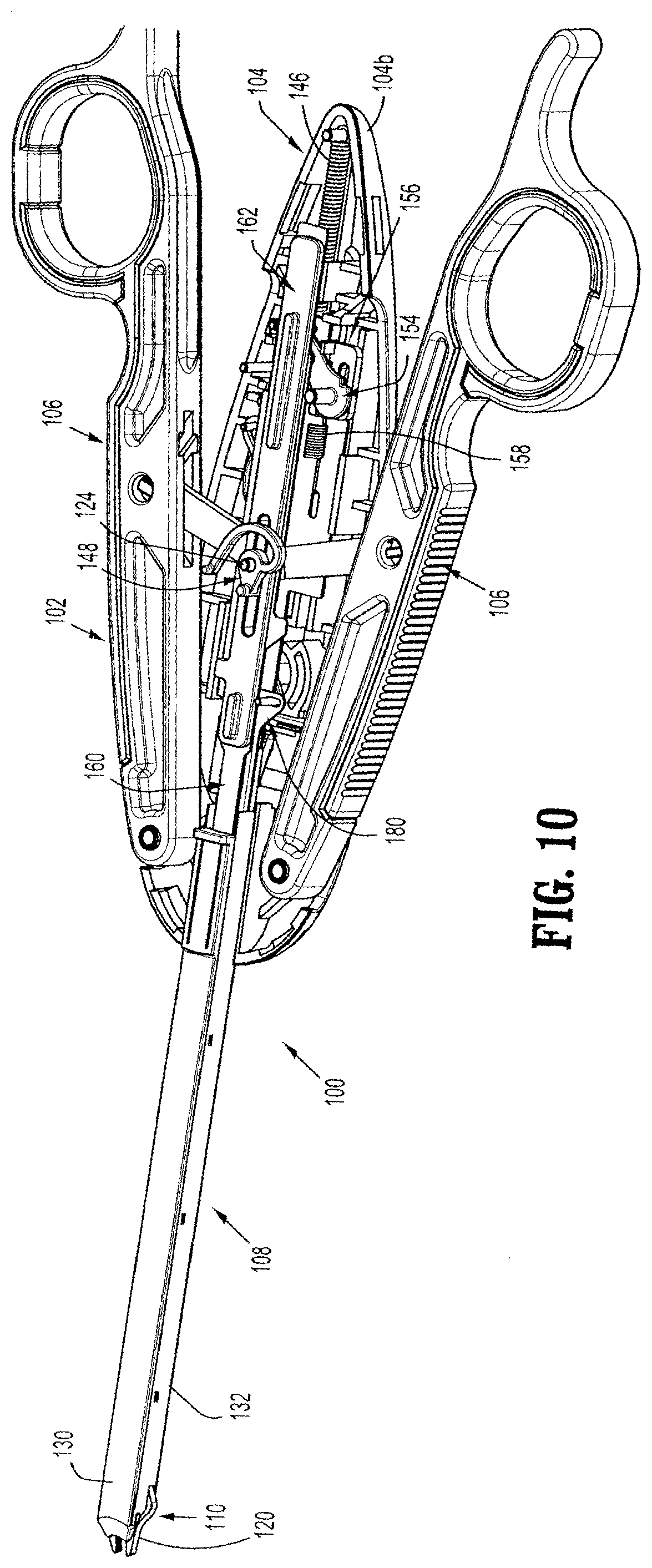
D00013

D00014

D00015

D00016

D00017

D00018

D00019

D00020

D00021

D00022

D00023
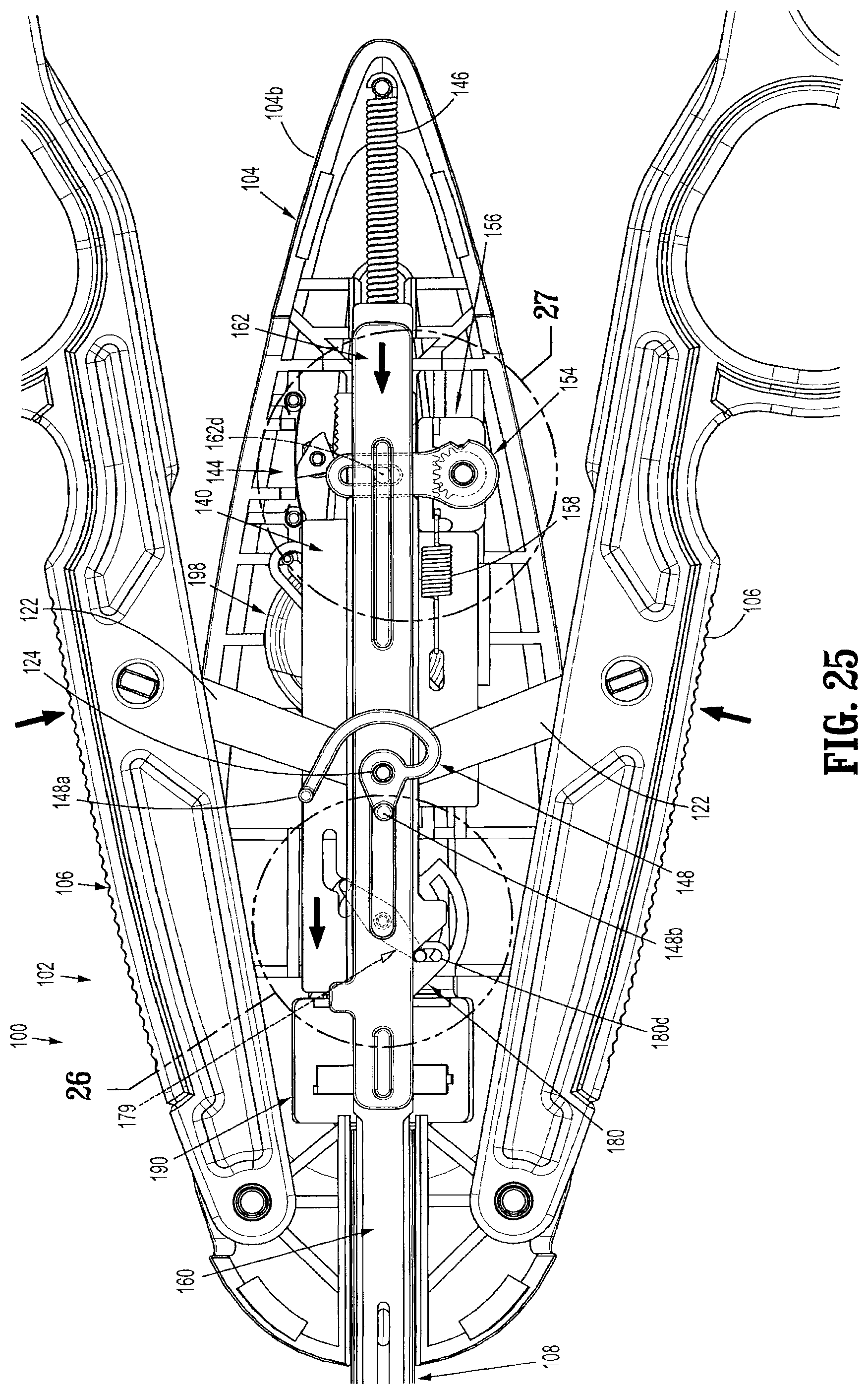
D00024

D00025

D00026

D00027

D00028
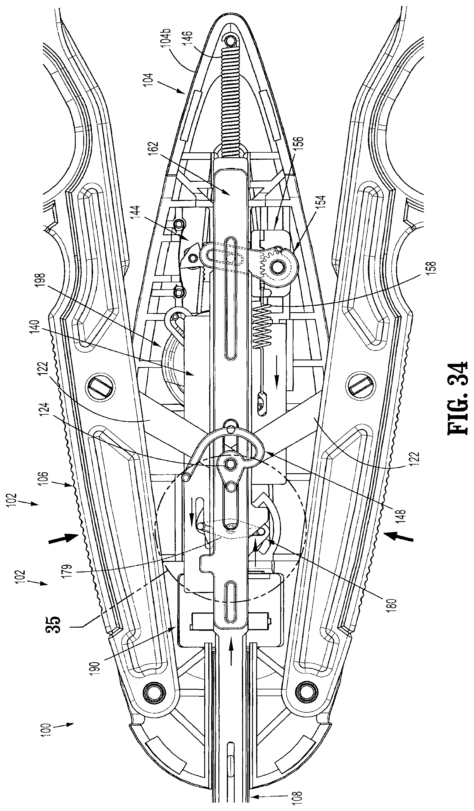
D00029

D00030

D00031
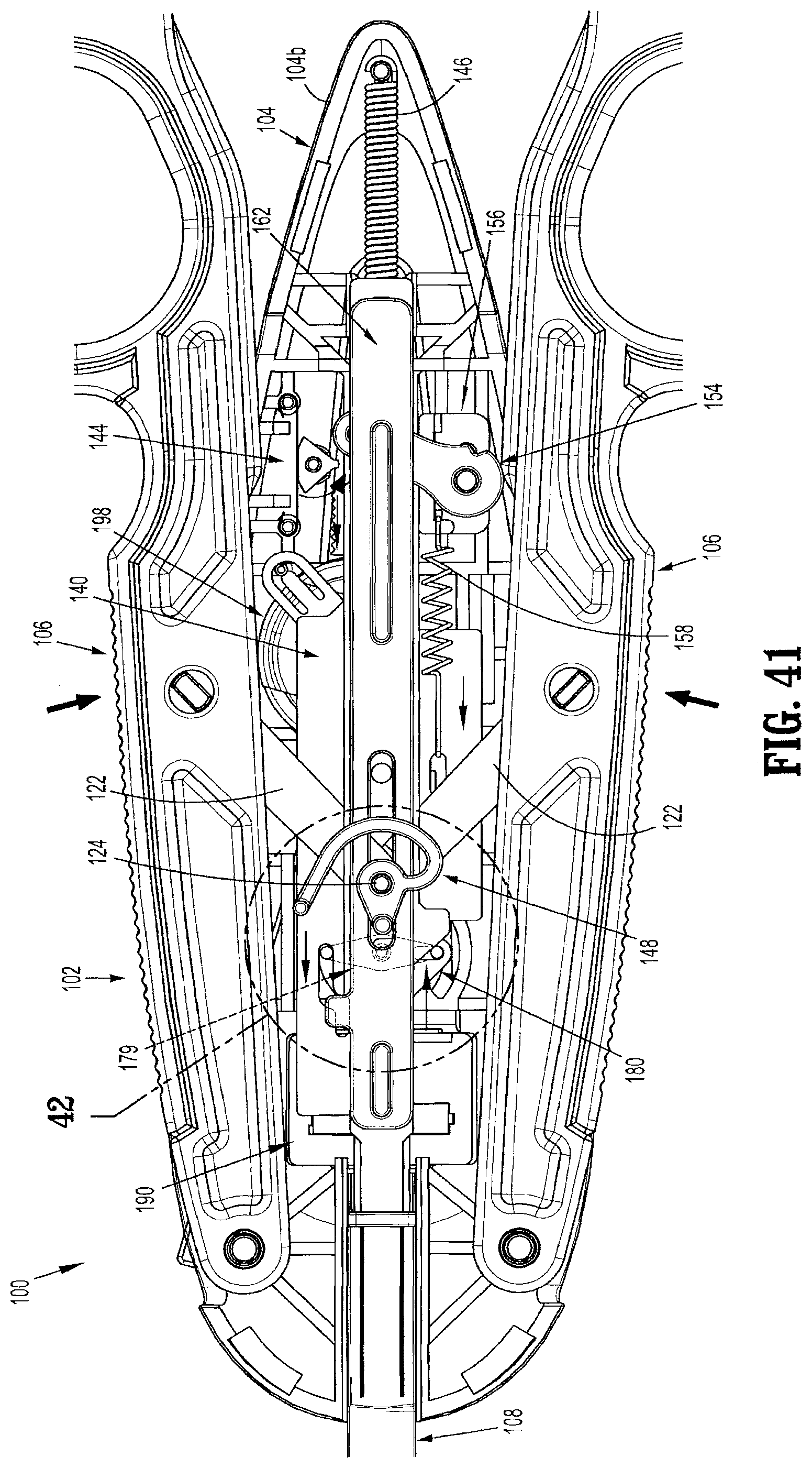
D00032

D00033

D00034

D00035

D00036

D00037

D00038

D00039

D00040

D00041

D00042

D00043
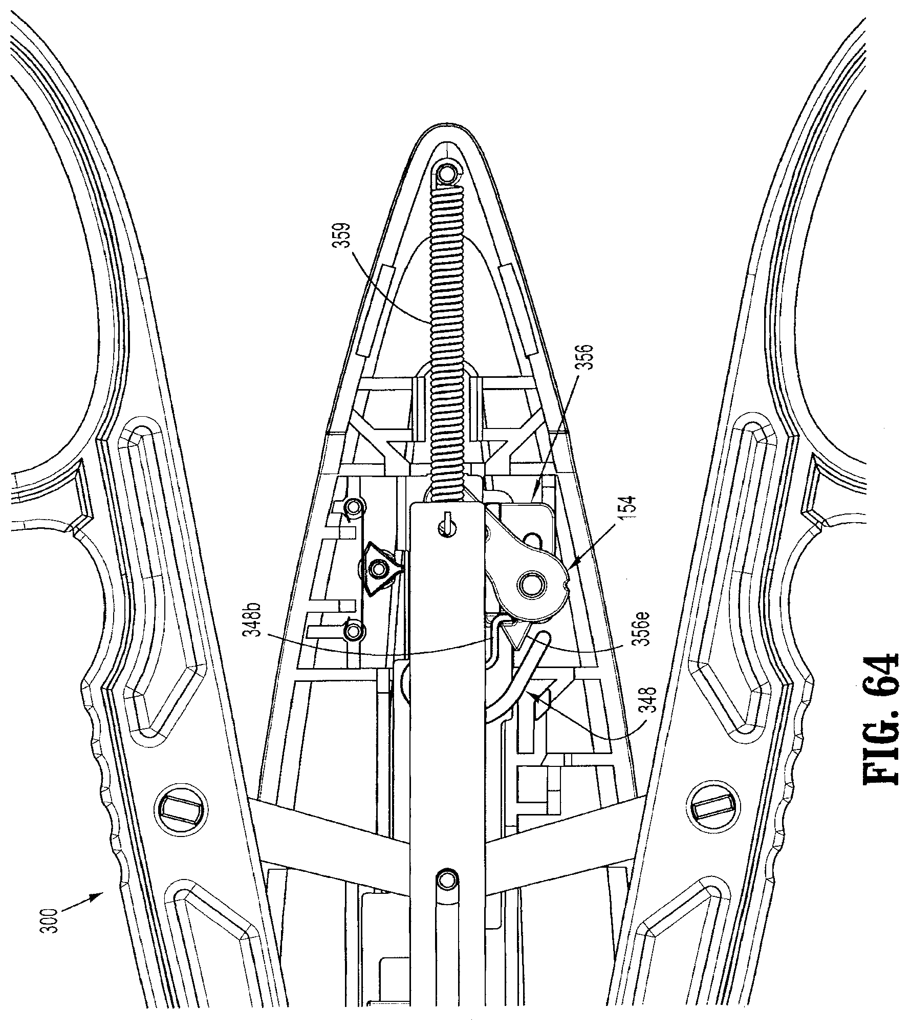
D00044
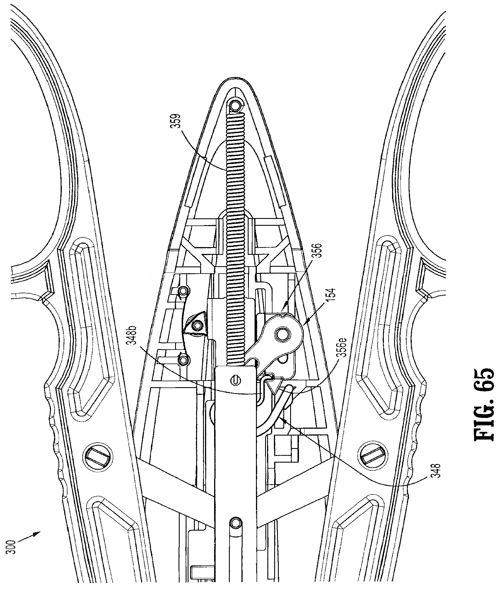
D00045

D00046

D00047

D00048

D00049

D00050

D00051

D00052

D00053

D00054

D00055

D00056

D00057
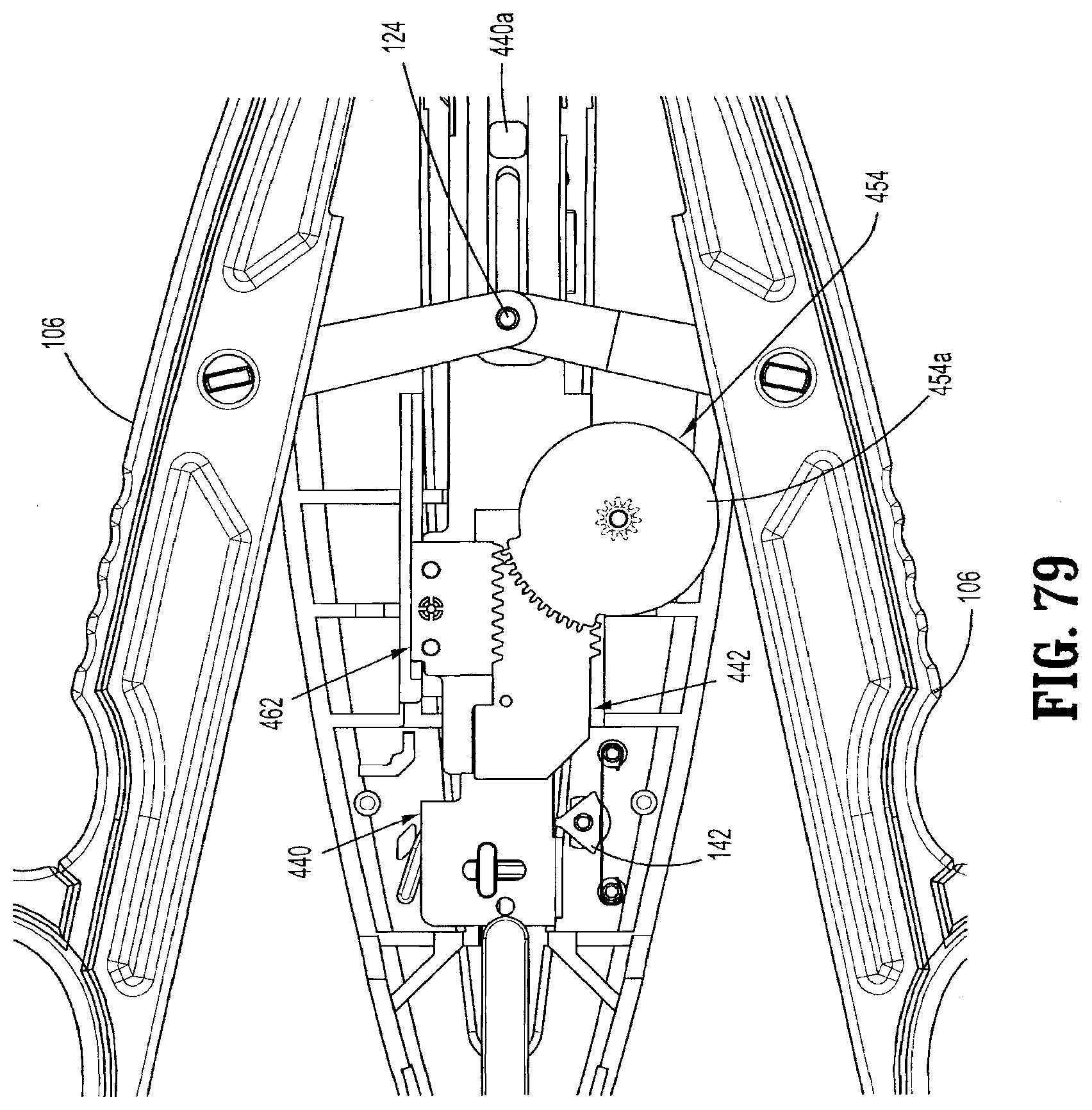
D00058

D00059
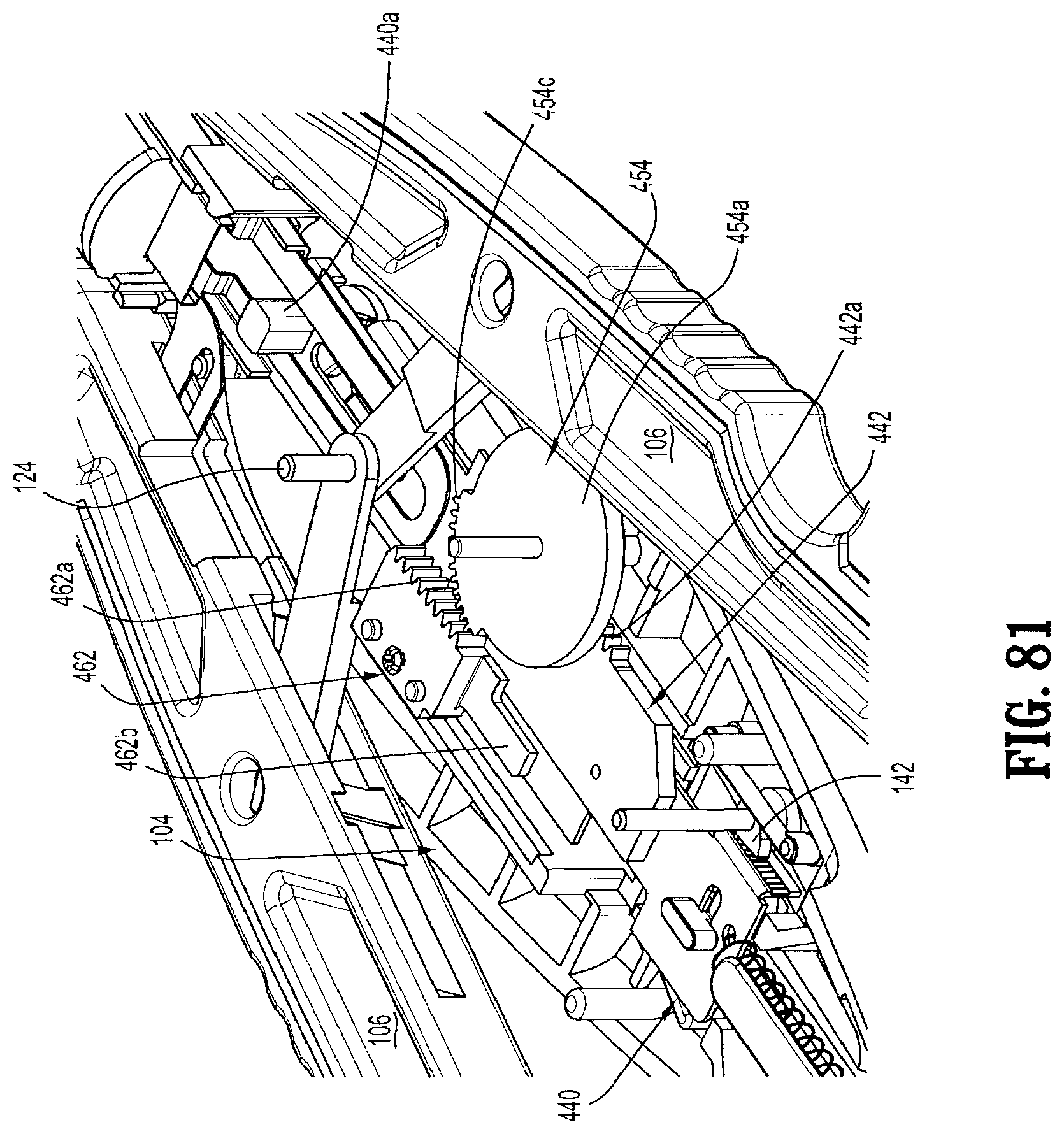
D00060

D00061

D00062

D00063

D00064

D00065

D00066

D00067

D00068

D00069

D00070

D00071

D00072
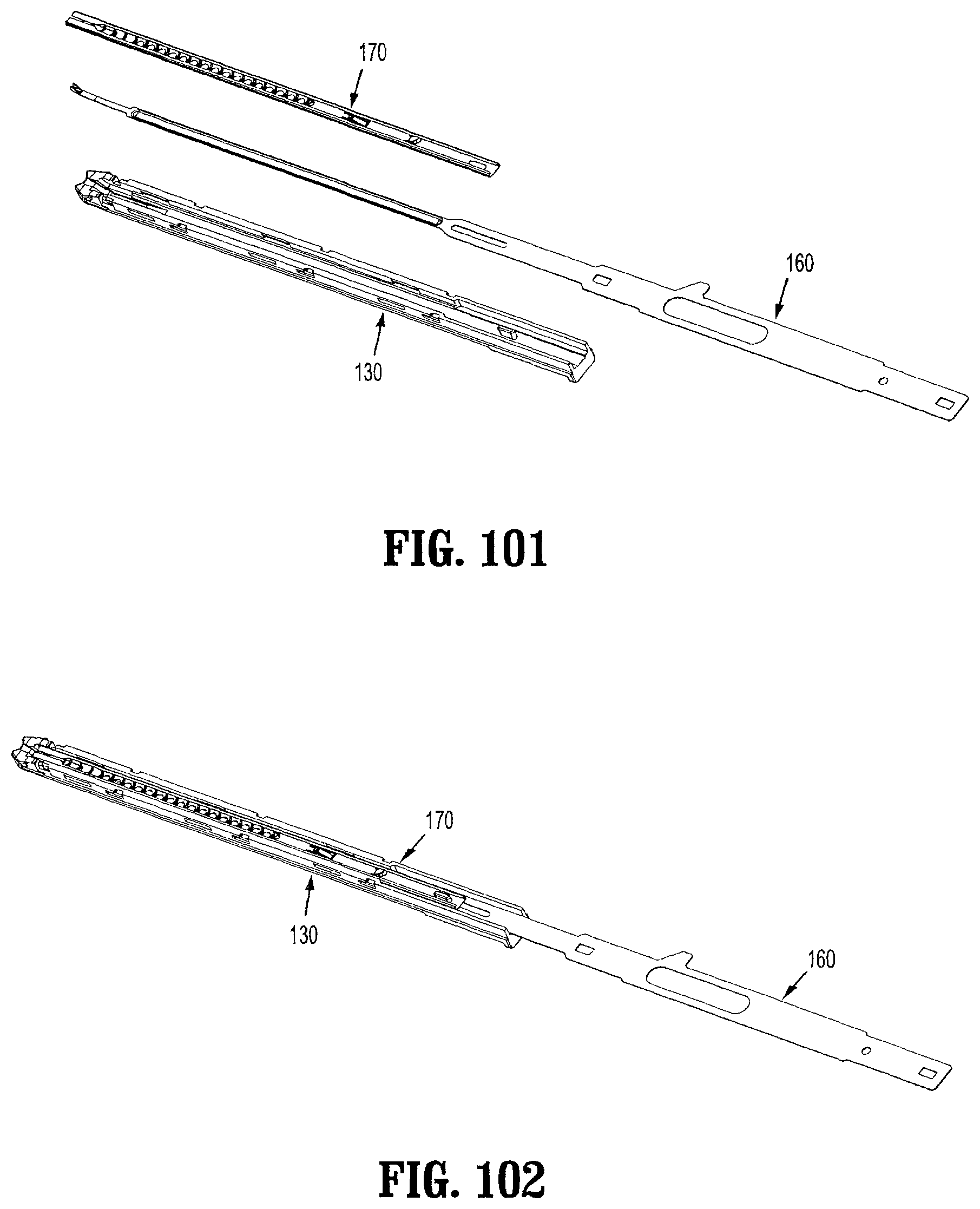
D00073

D00074

D00075

D00076

XML
uspto.report is an independent third-party trademark research tool that is not affiliated, endorsed, or sponsored by the United States Patent and Trademark Office (USPTO) or any other governmental organization. The information provided by uspto.report is based on publicly available data at the time of writing and is intended for informational purposes only.
While we strive to provide accurate and up-to-date information, we do not guarantee the accuracy, completeness, reliability, or suitability of the information displayed on this site. The use of this site is at your own risk. Any reliance you place on such information is therefore strictly at your own risk.
All official trademark data, including owner information, should be verified by visiting the official USPTO website at www.uspto.gov. This site is not intended to replace professional legal advice and should not be used as a substitute for consulting with a legal professional who is knowledgeable about trademark law.