Powered surgical stapling device platform
Zemlok , et al. Ja
U.S. patent number 10,542,983 [Application Number 15/450,787] was granted by the patent office on 2020-01-28 for powered surgical stapling device platform. This patent grant is currently assigned to Covidien LP. The grantee listed for this patent is Covidien LP. Invention is credited to David C. Racenet, Michael Zemlok.
View All Diagrams
| United States Patent | 10,542,983 |
| Zemlok , et al. | January 28, 2020 |
Powered surgical stapling device platform
Abstract
The present disclosure provides for a surgical instrument which includes a housing and an endoscopic portion extending distally from the housing and defining a first longitudinal axis. The surgical instrument also includes an end effector disposed adjacent a distal portion of the endoscopic portion. The end effector includes an anvil assembly and a cartridge assembly. The anvil assembly is pivotally coupled to the cartridge assembly to be movable from a first actuation position to at least one other second actuation position. The surgical instrument further includes a firing rod having a shaft defining a second longitudinal axis, the shaft having a cam member which is in mechanical cooperation with the anvil assembly and is configured to move the anvil assembly from the first actuation position to the at least one other second actuation position upon rotation of the firing rod about the second longitudinal axis.
| Inventors: | Zemlok; Michael (Prospect, CT), Racenet; David C. (Killingworth, CT) | ||||||||||
|---|---|---|---|---|---|---|---|---|---|---|---|
| Applicant: |
|
||||||||||
| Assignee: | Covidien LP (Mansfield,
MA) |
||||||||||
| Family ID: | 39675549 | ||||||||||
| Appl. No.: | 15/450,787 | ||||||||||
| Filed: | March 6, 2017 |
Prior Publication Data
| Document Identifier | Publication Date | |
|---|---|---|
| US 20170172574 A1 | Jun 22, 2017 | |
Related U.S. Patent Documents
| Application Number | Filing Date | Patent Number | Issue Date | ||
|---|---|---|---|---|---|
| 15180830 | Jun 13, 2016 | 9585664 | |||
| 13889580 | Jun 14, 2016 | 9364222 | |||
| 12869193 | Jun 11, 2013 | 8459521 | |||
| 11799766 | Nov 2, 2010 | 7823760 | |||
| Current U.S. Class: | 1/1 |
| Current CPC Class: | A61B 17/068 (20130101); A61B 17/07207 (20130101); A61B 17/105 (20130101); A61B 2017/00398 (20130101); A61B 2017/2905 (20130101); A61B 2017/07271 (20130101); A61B 2017/00734 (20130101); A61B 2017/2927 (20130101); A61B 2017/07257 (20130101); A61B 2017/00084 (20130101); A61B 2017/07221 (20130101); A61B 2017/00199 (20130101); A61B 2017/00221 (20130101); A61B 2090/0811 (20160201); A61B 2017/07278 (20130101) |
| Current International Class: | A61B 17/072 (20060101); A61B 17/068 (20060101); A61B 17/10 (20060101); A61B 90/00 (20160101); A61B 17/00 (20060101); A61B 17/29 (20060101) |
| Field of Search: | ;227/175.1,176.1 |
References Cited [Referenced By]
U.S. Patent Documents
| 37165 | December 1862 | Gary |
| 3079606 | March 1963 | Bobrov et al. |
| 3209754 | October 1965 | Brown |
| 3273562 | September 1966 | Brown |
| 3490675 | January 1970 | Green et al. |
| 3499591 | March 1970 | Green |
| 3528693 | September 1970 | Pearson et al. |
| 3744495 | July 1973 | Johnson |
| 3862631 | January 1975 | Austin |
| 3949924 | April 1976 | Green |
| 4060089 | November 1977 | Noiles |
| 4204623 | May 1980 | Green |
| 4217902 | August 1980 | March |
| 4263903 | April 1981 | Griggs |
| 4275813 | June 1981 | Noiles |
| 4331277 | May 1982 | Green |
| 4428376 | January 1984 | Mericle |
| 4429695 | February 1984 | Green |
| 4444181 | April 1984 | Wevers et al. |
| 4454875 | June 1984 | Pratt et al. |
| 4456006 | June 1984 | Wevers et al. |
| 4473077 | September 1984 | Noiles et al. |
| 4485816 | December 1984 | Krumme |
| 4485817 | December 1984 | Swiggett |
| 4488523 | December 1984 | Shichman |
| 4508253 | April 1985 | Green |
| 4508523 | April 1985 | Leu |
| 4522206 | June 1985 | Whipple et al. |
| 4534350 | August 1985 | Golden et al. |
| 4535772 | August 1985 | Sheehan |
| 4566620 | January 1986 | Green et al. |
| 4570623 | February 1986 | Ellison et al. |
| 4606343 | August 1986 | Conta et al. |
| 4606344 | August 1986 | Di Giovanni |
| 4610383 | September 1986 | Rothfuss et al. |
| 4612923 | September 1986 | Kronenthal |
| 4612933 | September 1986 | Brinkerhoff et al. |
| D286442 | October 1986 | Korthoff et al. |
| 4627437 | December 1986 | Bedi et al. |
| 4635637 | January 1987 | Schreiber |
| 4662371 | May 1987 | Whipple et al. |
| 4671280 | June 1987 | Dorband et al. |
| 4705038 | November 1987 | Sjostrom et al. |
| 4712550 | December 1987 | Sinnett |
| 4719917 | January 1988 | Barrows et al. |
| 4724839 | February 1988 | Bedi et al. |
| 4805617 | February 1989 | Bedi et al. |
| 4807628 | February 1989 | Peters et al. |
| 4852558 | August 1989 | Outerbridge |
| 4913144 | April 1990 | Del Medico |
| 4930494 | June 1990 | Takehana et al. |
| 4954952 | September 1990 | Ubhayakar et al. |
| 4960420 | October 1990 | Goble et al. |
| 4962877 | October 1990 | Hervas |
| 4990153 | February 1991 | Richards |
| 4994073 | February 1991 | Green |
| 4995877 | February 1991 | Ams et al. |
| 5040715 | August 1991 | Green et al. |
| 5042707 | August 1991 | Taheri |
| 5065929 | November 1991 | Schulze et al. |
| 5089009 | February 1992 | Green |
| 5108422 | April 1992 | Green et al. |
| 5114399 | May 1992 | Kovalcheck |
| 5129570 | July 1992 | Schulze et al. |
| 5143453 | September 1992 | Weynant nee Girones |
| 5203864 | April 1993 | Phillips |
| 5207697 | May 1993 | Carusillo et al. |
| 5209756 | May 1993 | Seedhom et al. |
| 5246443 | September 1993 | Mai |
| 5254130 | October 1993 | Poncet et al. |
| 5258008 | November 1993 | Wilk |
| 5271381 | December 1993 | Ailinger et al. |
| 5271543 | December 1993 | Grant et al. |
| RE34519 | January 1994 | Fox et al. |
| 5282829 | February 1994 | Hermes |
| 5300081 | April 1994 | Young et al. |
| 5307976 | May 1994 | Olson et al. |
| 5312023 | May 1994 | Green et al. |
| 5312024 | May 1994 | Grant et al. |
| 5313935 | May 1994 | Kortenbach et al. |
| 5318221 | June 1994 | Green et al. |
| 5326013 | July 1994 | Green et al. |
| 5330486 | July 1994 | Wilk |
| 5332142 | July 1994 | Robinson et al. |
| 5342376 | August 1994 | Ruff |
| 5350355 | September 1994 | Sklar |
| 5356064 | October 1994 | Green et al. |
| 5359993 | November 1994 | Slater et al. |
| 5364001 | November 1994 | Bryan |
| 5381943 | January 1995 | Allen et al. |
| 5383874 | January 1995 | Jackson et al. |
| 5383880 | January 1995 | Hooven |
| 5389098 | February 1995 | Tsuruta et al. |
| 5395030 | March 1995 | Kuramoto et al. |
| 5395033 | March 1995 | Byrne et al. |
| 5400267 | March 1995 | Denen et al. |
| 5403312 | April 1995 | Yates et al. |
| 5405344 | April 1995 | Williamson et al. |
| 5411508 | May 1995 | Bessler et al. |
| 5413267 | May 1995 | Solyntjes et al. |
| 5431323 | July 1995 | Smith et al. |
| 5464144 | November 1995 | Guy et al. |
| 5467911 | November 1995 | Tsuruta et al. |
| 5478344 | December 1995 | Stone et al. |
| 5482100 | January 1996 | Kuhar |
| 5485947 | January 1996 | Olson et al. |
| 5485952 | January 1996 | Fontayne |
| 5487499 | January 1996 | Sorrentino et al. |
| 5497933 | March 1996 | DeFonzo et al. |
| 5500000 | March 1996 | Feagin et al. |
| 5503320 | April 1996 | Webster et al. |
| 5507743 | April 1996 | Edwards et al. |
| 5518163 | May 1996 | Hooven |
| 5518164 | May 1996 | Hooven |
| 5526822 | June 1996 | Burbank et al. |
| 5529235 | June 1996 | Boiarski et al. |
| 5531744 | July 1996 | Nardella et al. |
| 5533661 | July 1996 | Main et al. |
| 5535934 | July 1996 | Boiarski et al. |
| 5535937 | July 1996 | Boiarski et al. |
| 5558671 | September 1996 | Yates |
| 5560532 | October 1996 | DeFonzo et al. |
| 5562239 | October 1996 | Boiarski et al. |
| 5571285 | November 1996 | Chow et al. |
| 5575799 | November 1996 | Bolanos et al. |
| 5582611 | December 1996 | Tsuruta et al. |
| 5584835 | December 1996 | Greenfield |
| 5601224 | February 1997 | Bishop et al. |
| 5601558 | February 1997 | Torrie et al. |
| 5607095 | March 1997 | Smith et al. |
| 5609285 | March 1997 | Grant et al. |
| 5609560 | March 1997 | Ichikawa et al. |
| 5624452 | April 1997 | Yates |
| 5632433 | May 1997 | Grant et al. |
| 5634926 | June 1997 | Jobe |
| 5642848 | July 1997 | Ludwig et al. |
| 5653374 | August 1997 | Young et al. |
| 5658300 | August 1997 | Bito et al. |
| 5658312 | August 1997 | Green et al. |
| 5662662 | September 1997 | Bishop et al. |
| 5665085 | September 1997 | Nardella |
| 5667513 | September 1997 | Torrie et al. |
| 5667517 | September 1997 | Hooven |
| 5667527 | September 1997 | Cook |
| 5669544 | September 1997 | Schulze et al. |
| 5673841 | October 1997 | Schulze et al. |
| 5676674 | October 1997 | Bolanos et al. |
| 5680981 | October 1997 | Mililli et al. |
| 5680982 | October 1997 | Schulze et al. |
| 5692668 | December 1997 | Schulze et al. |
| 5695506 | December 1997 | Pike et al. |
| 5695524 | December 1997 | Kelley et al. |
| 5702447 | December 1997 | Walch et al. |
| 5704534 | January 1998 | Huitema et al. |
| 5713505 | February 1998 | Huitema |
| 5713896 | February 1998 | Nardella |
| 5715987 | February 1998 | Kelley et al. |
| 5716366 | February 1998 | Yates |
| 5720753 | February 1998 | Sander et al. |
| 5725529 | March 1998 | Nicholson et al. |
| 5728110 | March 1998 | Vidal et al. |
| 5728116 | March 1998 | Rosenman |
| 5730757 | March 1998 | Benetti et al. |
| 5735848 | April 1998 | Yates et al. |
| 5738474 | April 1998 | Blewett |
| 5755726 | May 1998 | Pratt et al. |
| 5759171 | June 1998 | Coelho et al. |
| 5769303 | June 1998 | Knodel et al. |
| 5779130 | July 1998 | Alesi et al. |
| 5782397 | July 1998 | Koukline |
| 5785713 | July 1998 | Jobe |
| 5788698 | August 1998 | Savornin |
| 5810811 | September 1998 | Yates et al. |
| 5814038 | September 1998 | Jensen et al. |
| 5823066 | October 1998 | Huitema et al. |
| 5829662 | November 1998 | Allen et al. |
| 5830121 | November 1998 | Enomoto et al. |
| 5849023 | December 1998 | Mericle |
| 5849028 | December 1998 | Chen |
| 5855311 | January 1999 | Hamblin et al. |
| 5861005 | January 1999 | Kontos |
| 5865361 | February 1999 | Milliman et al. |
| 5876401 | March 1999 | Schulze et al. |
| 5891156 | April 1999 | Gessner et al. |
| 5893813 | April 1999 | Yamamoto |
| 5895396 | April 1999 | Day et al. |
| 5906607 | May 1999 | Taylor et al. |
| 5911721 | June 1999 | Nicholson et al. |
| 5916146 | June 1999 | Allotta et al. |
| 5918791 | July 1999 | Sorrentino et al. |
| 5928222 | July 1999 | Kleinerman |
| 5944717 | August 1999 | Lee et al. |
| 5944736 | August 1999 | Taylor et al. |
| 5954259 | September 1999 | Viola et al. |
| 5961521 | October 1999 | Roger |
| 5964394 | October 1999 | Robertson |
| 5968044 | October 1999 | Nicholson et al. |
| 5976171 | November 1999 | Taylor |
| 5980518 | November 1999 | Carr et al. |
| 5980548 | November 1999 | Evans et al. |
| 5991355 | November 1999 | Dahlke |
| 5991650 | November 1999 | Swanson et al. |
| 5992724 | November 1999 | Snyder |
| 5997552 | December 1999 | Person et al. |
| 6004335 | December 1999 | Vaitekunas et al. |
| 6007550 | December 1999 | Wang et al. |
| 6010054 | January 2000 | Johnson et al. |
| 6013077 | January 2000 | Harwin |
| 6015417 | January 2000 | Reynolds, Jr. |
| 6017354 | January 2000 | Culp et al. |
| 6030410 | February 2000 | Zurbrugg |
| 6032849 | March 2000 | Mastri et al. |
| 6039731 | March 2000 | Taylor et al. |
| 6051007 | April 2000 | Hogendijk et al. |
| 6063078 | May 2000 | Wittkampf |
| 6063095 | May 2000 | Wang et al. |
| 6077246 | June 2000 | Kullas et al. |
| 6079606 | June 2000 | Milliman et al. |
| 6080150 | June 2000 | Gough |
| 6083242 | July 2000 | Cook |
| 6090123 | July 2000 | Culp et al. |
| 6092422 | July 2000 | Binnig et al. |
| 6109500 | August 2000 | Alli et al. |
| 6113592 | September 2000 | Taylor |
| 6123702 | September 2000 | Swanson et al. |
| H1904 | October 2000 | Yates et al. |
| 6126058 | October 2000 | Adams et al. |
| 6126651 | October 2000 | Mayer |
| 6127811 | October 2000 | Shenoy et al. |
| 6132425 | October 2000 | Gough |
| 6165169 | December 2000 | Panescu et al. |
| 6166538 | December 2000 | D'Alfonso |
| 6179840 | January 2001 | Bowman |
| 6187009 | February 2001 | Herzog et al. |
| 6187019 | February 2001 | Stefanchik et al. |
| 6190401 | February 2001 | Green et al. |
| 6193501 | February 2001 | Masel et al. |
| 6202914 | March 2001 | Geiste et al. |
| 6217573 | April 2001 | Webster |
| 6228534 | May 2001 | Takeuchi et al. |
| 6231565 | May 2001 | Tovey et al. |
| 6236874 | May 2001 | Devlin et al. |
| 6237604 | May 2001 | Burnside et al. |
| 6241139 | June 2001 | Milliman et al. |
| 6245065 | June 2001 | Panescu et al. |
| 6248117 | June 2001 | Blatter |
| 6250532 | June 2001 | Green et al. |
| 6258111 | July 2001 | Ross et al. |
| 6264086 | July 2001 | McGuckin, Jr. |
| 6264087 | July 2001 | Whitman |
| 6264653 | July 2001 | Falwell |
| 6281471 | August 2001 | Smart |
| 6288534 | September 2001 | Starkweather et al. |
| 6290701 | September 2001 | Enayati |
| 6293943 | September 2001 | Panescu et al. |
| 6295330 | September 2001 | Skog et al. |
| 6315184 | November 2001 | Whitman |
| 6329778 | December 2001 | Culp et al. |
| 6330965 | December 2001 | Milliman et al. |
| 6346104 | February 2002 | Daly et al. |
| 6355066 | March 2002 | Kim |
| 6364884 | April 2002 | Bowman et al. |
| 6387092 | May 2002 | Burnside et al. |
| 6388240 | May 2002 | Schulz et al. |
| 6402766 | June 2002 | Bowman et al. |
| H2037 | July 2002 | Yates et al. |
| 6412279 | July 2002 | Coleman et al. |
| 6425903 | July 2002 | Voegele |
| 6436097 | August 2002 | Nardella |
| 6436107 | August 2002 | Wang et al. |
| 6436110 | August 2002 | Bowman et al. |
| 6443973 | September 2002 | Whitman |
| 6447517 | September 2002 | Bowman |
| 6461372 | October 2002 | Jensen et al. |
| 6478210 | November 2002 | Adams et al. |
| 6497707 | December 2002 | Bowman et al. |
| 6505768 | January 2003 | Whitman |
| 6515273 | February 2003 | Al-Ali |
| 6524316 | February 2003 | Nicholson et al. |
| 6533157 | March 2003 | Whitman |
| 6540751 | April 2003 | Enayati |
| 6544273 | April 2003 | Harari et al. |
| 6554852 | April 2003 | Oberlander |
| 6562071 | May 2003 | Jarvinen |
| 6578579 | June 2003 | Burnside et al. |
| 6601748 | August 2003 | Fung et al. |
| 6601749 | August 2003 | Sullivan et al. |
| 6602252 | August 2003 | Mollenauer |
| 6611793 | August 2003 | Burnside et al. |
| 6616821 | September 2003 | Broadley et al. |
| 6629986 | October 2003 | Ross et al. |
| 6651669 | November 2003 | Burnside |
| 6656177 | December 2003 | Truckai et al. |
| 6669073 | December 2003 | Milliman et al. |
| 6669705 | December 2003 | Westhaver et al. |
| 6696008 | February 2004 | Brandinger |
| 6698643 | March 2004 | Whitman |
| 6699177 | March 2004 | Wang et al. |
| 6716233 | April 2004 | Whitman |
| 6736085 | May 2004 | Esnouf |
| 6743239 | June 2004 | Kuehn et al. |
| 6792390 | September 2004 | Burnside et al. |
| 6793652 | September 2004 | Whitman et al. |
| 6817508 | November 2004 | Racenet et al. |
| 6830174 | December 2004 | Hillstead et al. |
| 6843403 | January 2005 | Whitman |
| 6846307 | January 2005 | Whitman et al. |
| 6846308 | January 2005 | Whitman et al. |
| 6846309 | January 2005 | Whitman et al. |
| 6849071 | February 2005 | Whitman et al. |
| 6861639 | March 2005 | Al-Ali |
| 6872214 | March 2005 | Sonnenschein et al. |
| 6899538 | May 2005 | Matoba |
| 6900004 | May 2005 | Satake |
| 6905057 | June 2005 | Swayze et al. |
| 6926636 | August 2005 | Luper |
| 6953139 | October 2005 | Milliman et al. |
| 6959852 | November 2005 | Shelton, IV et al. |
| 6964363 | November 2005 | Wales et al. |
| 6979328 | December 2005 | Baerveldt et al. |
| 6981628 | January 2006 | Wales |
| 6981941 | January 2006 | Whitman et al. |
| 6988649 | January 2006 | Shelton, IV et al. |
| 7000819 | February 2006 | Swayze et al. |
| 7032798 | April 2006 | Whitman et al. |
| 7044353 | May 2006 | Mastri et al. |
| 7048687 | May 2006 | Reuss et al. |
| 7055731 | June 2006 | Shelton, IV et al. |
| 7059508 | June 2006 | Shelton, IV et al. |
| 7077856 | July 2006 | Whitman |
| 7083075 | August 2006 | Swayze et al. |
| 7097089 | August 2006 | Marczyk |
| 7111769 | September 2006 | Wales et al. |
| 7118564 | October 2006 | Ritchie et al. |
| 7122029 | October 2006 | Koop et al. |
| 7128253 | October 2006 | Mastri et al. |
| 7128254 | October 2006 | Shelton, IV et al. |
| 7140528 | November 2006 | Shelton, IV |
| 7143924 | December 2006 | Scirica et al. |
| 7143925 | December 2006 | Shelton, IV et al. |
| 7143926 | December 2006 | Shelton, IV et al. |
| 7147138 | December 2006 | Shelton, IV |
| 7186966 | March 2007 | Al-Ali |
| 7193519 | March 2007 | Root et al. |
| 7217269 | May 2007 | El-Galley et al. |
| 7220232 | May 2007 | Suorsa et al. |
| 7240817 | July 2007 | Higuchi |
| 7241270 | July 2007 | Horzewski et al. |
| 7246734 | July 2007 | Shelton, IV |
| 7303108 | December 2007 | Shelton, IV |
| 7328828 | February 2008 | Ortiz et al. |
| 7335169 | February 2008 | Thompson et al. |
| 7364061 | April 2008 | Swayze et al. |
| 7380695 | June 2008 | Doll et al. |
| 7380696 | June 2008 | Shelton, IV et al. |
| 7404508 | July 2008 | Smith et al. |
| 7416101 | August 2008 | Shelton, IV et al. |
| 7419080 | September 2008 | Smith et al. |
| 7422136 | September 2008 | Marczyk |
| 7422139 | September 2008 | Shelton, IV et al. |
| 7431188 | October 2008 | Marczyk |
| 7431189 | October 2008 | Shelton, IV et al. |
| 7434715 | October 2008 | Shelton, IV et al. |
| 7441684 | October 2008 | Shelton, IV et al. |
| 7448525 | November 2008 | Shelton, IV et al. |
| 7461767 | December 2008 | Viola et al. |
| 7464846 | December 2008 | Shelton, IV et al. |
| 7464847 | December 2008 | Viola et al. |
| 7464849 | December 2008 | Shelton, IV et al. |
| 7481348 | January 2009 | Marczyk |
| 7487899 | February 2009 | Shelton, IV et al. |
| 7549563 | June 2009 | Mather et al. |
| 7552854 | June 2009 | Wixey et al. |
| 7556185 | July 2009 | Viola |
| 7568603 | August 2009 | Shelton, IV et al. |
| 7637409 | December 2009 | Marczyk |
| 7641093 | January 2010 | Doll et al. |
| 7644848 | January 2010 | Swayze et al. |
| 7648055 | January 2010 | Marczyk |
| 7670334 | March 2010 | Hueil et al. |
| 7678117 | March 2010 | Hinman et al. |
| 7721931 | May 2010 | Shelton, IV et al. |
| 7740159 | June 2010 | Shelton, IV et al. |
| 7753248 | July 2010 | Viola |
| 7757925 | July 2010 | Viola et al. |
| 7766207 | August 2010 | Mather et al. |
| 7766210 | August 2010 | Shelton, IV et al. |
| 7770775 | August 2010 | Shelton, IV et al. |
| 7815090 | October 2010 | Marczyk |
| 7823760 | November 2010 | Zemlok |
| 7845534 | December 2010 | Viola et al. |
| 7950560 | May 2011 | Zemlok et al. |
| 8052024 | November 2011 | Viola et al. |
| 8132705 | March 2012 | Viola et al. |
| 8241322 | August 2012 | Whitman et al. |
| 8459521 | June 2013 | Zemlok et al. |
| 9364222 | June 2016 | Zemlok et al. |
| 9585664 | March 2017 | Zemlok et al. |
| 2002/0103489 | August 2002 | Ku |
| 2002/0111641 | August 2002 | Peterson et al. |
| 2002/0165541 | November 2002 | Whitman |
| 2003/0114851 | June 2003 | Truckai et al. |
| 2003/0120306 | June 2003 | Burbank et al. |
| 2004/0232201 | November 2004 | Wenchell et al. |
| 2005/0010235 | January 2005 | VanDusseldorp |
| 2005/0131390 | June 2005 | Heinrich et al. |
| 2005/0139636 | June 2005 | Schwemberger et al. |
| 2005/0145674 | July 2005 | Sonnenschein et al. |
| 2005/0177176 | August 2005 | Gerbi et al. |
| 2005/0187576 | August 2005 | Whitman et al. |
| 2005/0192609 | September 2005 | Whitman et al. |
| 2005/0247753 | November 2005 | Kelly et al. |
| 2005/0273085 | December 2005 | Hinman et al. |
| 2006/0000867 | January 2006 | Shelton et al. |
| 2007/0023477 | February 2007 | Whitman et al. |
| 2007/0029363 | February 2007 | Popov |
| 2007/0039995 | February 2007 | Schwemberger et al. |
| 2007/0084897 | April 2007 | Shelton et al. |
| 2007/0102472 | May 2007 | Shelton |
| 2007/0175947 | August 2007 | Ortiz et al. |
| 2007/0175949 | August 2007 | Shelton et al. |
| 2007/0175950 | August 2007 | Shelton et al. |
| 2007/0175951 | August 2007 | Shelton et al. |
| 2007/0175953 | August 2007 | Shelton et al. |
| 2007/0175955 | August 2007 | Shelton et al. |
| 2007/0219563 | September 2007 | Voegele |
| 2007/0265640 | November 2007 | Kortenbach et al. |
| 2008/0029570 | February 2008 | Shelton et al. |
| 2008/0029573 | February 2008 | Shelton et al. |
| 2008/0029574 | February 2008 | Shelton et al. |
| 2008/0029575 | February 2008 | Shelton et al. |
| 2008/0135600 | June 2008 | Hiranuma et al. |
| 2008/0169329 | July 2008 | Shelton et al. |
| 2008/0185419 | August 2008 | Smith et al. |
| 2008/0197167 | August 2008 | Viola et al. |
| 2008/0245842 | October 2008 | Marczyk |
| 2008/0251568 | October 2008 | Zemlok et al. |
| 2008/0255413 | October 2008 | Zemlok et al. |
| 2008/0255418 | October 2008 | Zemlok et al. |
| 2008/0255607 | October 2008 | Zemlok |
| 2008/0281353 | November 2008 | Aranyi et al. |
| 2008/0314959 | December 2008 | Viola et al. |
| 2009/0032568 | February 2009 | Viola et al. |
| 2009/0090201 | April 2009 | Viola |
| 2009/0090763 | April 2009 | Zemlok et al. |
| 2009/0108048 | April 2009 | Zemlok et al. |
| 2010/0001036 | January 2010 | Marczyk et al. |
| 2010/0012702 | January 2010 | Marczyk |
| 2010/0089972 | April 2010 | Marczyk |
| 2010/0163596 | July 2010 | Marczyk |
| 2010/0200636 | August 2010 | Zemlok et al. |
| 2010/0252610 | October 2010 | Viola |
| 2010/0312257 | December 2010 | Aranyi |
| 2010/0320254 | December 2010 | Zemlok et al. |
| 2011/0034910 | February 2011 | Ross et al. |
| 2014/0171923 | June 2014 | Aranyi |
| 0634144 | Jan 1995 | EP | |||
| 0647431 | Apr 1995 | EP | |||
| 0705571 | Apr 1996 | EP | |||
| 0738501 | Oct 1996 | EP | |||
| 0770354 | May 1997 | EP | |||
| 537570 | Jan 1998 | EP | |||
| 1070487 | Jan 2001 | EP | |||
| 1769754 | Apr 2007 | EP | |||
| 1813203 | Aug 2007 | EP | |||
| 2 849 589 | Jul 2004 | FR | |||
| 9729694 | Aug 1997 | WO | |||
| 9740760 | Nov 1997 | WO | |||
| 9837825 | Sep 1998 | WO | |||
| 9952489 | Oct 1999 | WO | |||
| 2002/34140 | May 2002 | WO | |||
| 2003/026511 | Apr 2003 | WO | |||
| 2003/030743 | Apr 2003 | WO | |||
| 2004032760 | Apr 2004 | WO | |||
| 2007030753 | Mar 2007 | WO | |||
| 2007118179 | Oct 2007 | WO | |||
Other References
|
Extended European Search Report issued in Appl. No. EP 17172955.1 dated Dec. 1, 2017 (8 pages). cited by applicant . Extended European Search Report for EP 08 25 1568 dated Jun. 11, 2015. cited by applicant . European Search Report dated Jul. 28, 2011 for EP 11 15 2266. cited by applicant . Detemple, R, "Microtechnology in Modem Health Care", Med Device Technol. 9(9):18-25 (1998). cited by applicant . European Search Report EP 06026840 dated May 10, 2007. cited by applicant . European Search Report EP 08251357.3 dated Sep. 29, 2009. cited by applicant . European Search Report EP 08252703.7 dated Oct. 31, 2008. cited by applicant . European Search Report EP 08253184.9 dated Feb. 27, 2009. cited by applicant . International Search Report PCT/US06/21524 dated May 28, 2008. cited by applicant . Patent Examination Report No. 1 for Australian Patent Appln. No. AU 2014-200667 dated Mar. 5, 2015. cited by applicant . Australian Examination Report issued in Appl. No. AU 2015243017 dated Dec. 5, 2016. cited by applicant . Canadian Office Action from Appl. No. CA 2,627,954 dated May 12, 2014. cited by applicant . Australian Examination Report issued in Appl. No. AU 2008201630 dated Aug. 1, 2013. cited by applicant. |
Primary Examiner: Lopez; Michelle
Parent Case Text
CROSS-REFERENCE TO RELATED APPLICATIONS
The present application is a continuation application of U.S. patent application Ser. No. 15/180,830, filed on Jun. 13, 2016, now U.S. Pat. No. 9,585,664, which is a continuation application of U.S. patent application Ser. No. 13/889,580, filed on May 8, 2013, now U.S. Pat. No. 9,364,222, which is a continuation application of U.S. patent application Ser. No. 12/869,193, filed on Aug. 26, 2010, now U.S. Pat. No. 8,459,521, which is a divisional application of U.S. application Ser. No. 11/799,766, filed on May 1, 2007, now U.S. Pat. No. 7,823,760, the entire contents of all of which are hereby incorporated herein by reference.
Claims
What is claimed is:
1. A powered surgical system comprising: a housing; a battery disposed in the housing; a motor coupled to the battery; a flexible shaft extending distally from the housing and defining a first longitudinal axis; an end effector disposed adjacent a distal portion of the flexible shaft, the end effector including a first jaw member and a second jaw member; a flexible firing rod disposed within the flexible shaft and defining a second longitudinal axis, the flexible firing rod rotatable by the motor about the second longitudinal axis; and a cam member disposed adjacent a distal portion of the flexible firing rod and having a pair of opposing camming surfaces, the cam member rotatable by the flexible firing rod such that one of the camming surfaces moves the first jaw member between a first position and a second position.
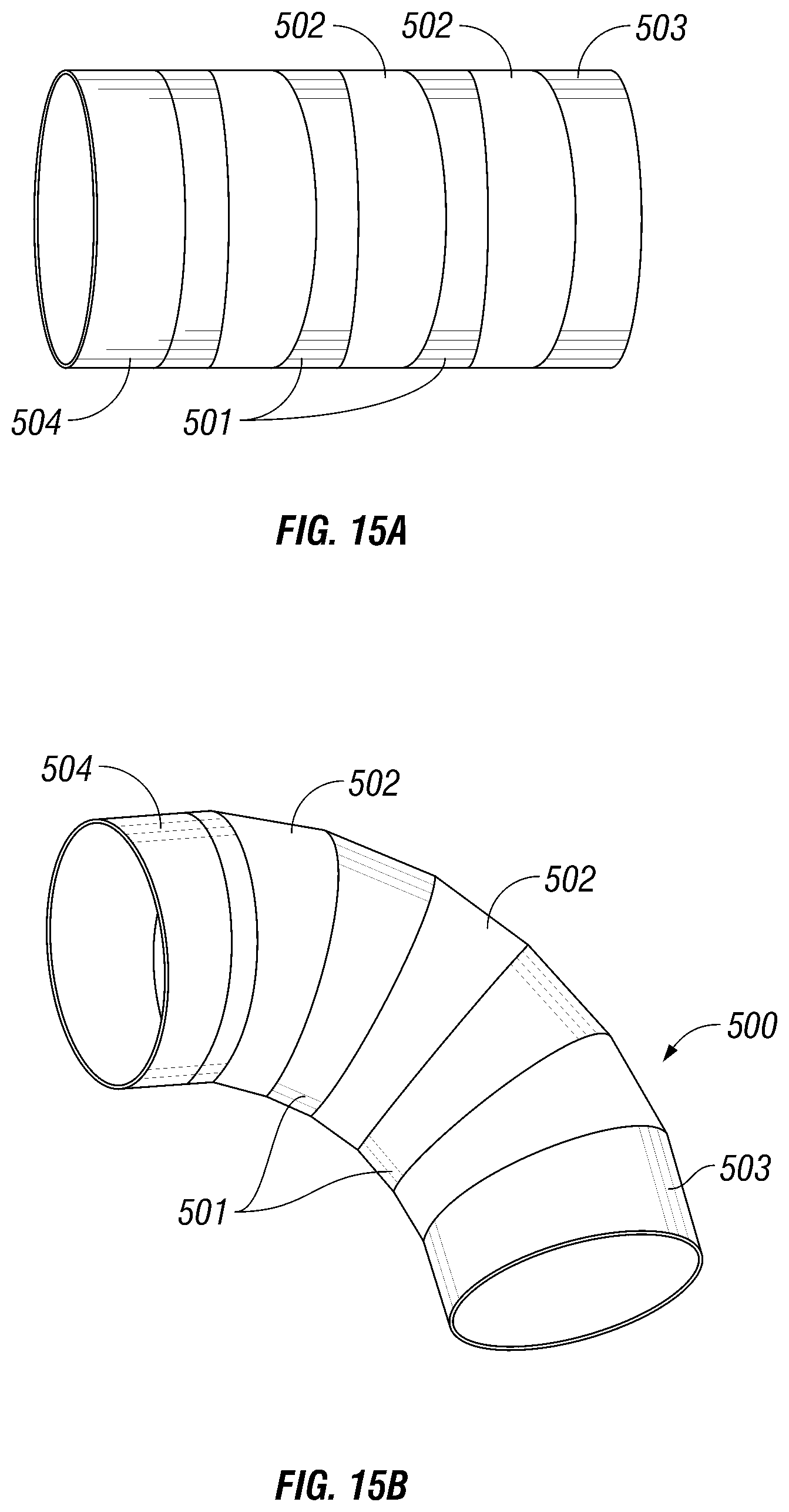
2. The powered surgical system according to claim 1, wherein the flexible shaft is movable between a straight configuration and an articulated configuration, the flexible shaft includes a plurality of interconnected angled outer tubes.
3. The powered surgical system according to claim 2, wherein each of the plurality of interconnected angled outer tubes has a narrow section and a wide section, such that when the flexible shaft is in the straight configuration, the narrow sections of the plurality of interconnected angled outer tubes alternate with the wide sections of the plurality of interconnected angled outer tubes, and when the flexible shaft is in the articulated configuration, the wide sections of the plurality of interconnected angled outer tubes are aligned and the narrow sections of the plurality of interconnected angled outer tubes are aligned.
4. The powered surgical system according to claim 3, further comprising: a drive gear disposed in the housing, and wherein the flexible shaft further includes a proximal end cap disposed on a proximal portion of the flexible shaft, the proximal end cap operatively coupled to the drive gear.
5. The powered surgical system according to claim 4, wherein the flexible shaft further includes a distal end cap disposed on a distal portion of the flexible shaft, the distal end cap operatively coupled to the end effector.
6. The powered surgical system according to claim 5, wherein each of the proximal end cap and the distal end cap includes an angled face, the proximal end cap configured to couple to one of the plurality of interconnected angled outer tubes at the proximal portion of the flexible shaft, and the distal end cap configured to couple to one of the plurality of interconnected angled outer tubes at the distal portion of the flexible shaft.
7. The powered surgical system according to claim 6, wherein the proximal end cap is rotated by rotation of the drive gear.
8. The powered surgical system according to claim 7, wherein the distal end cap is fixed from rotation.
9. The powered surgical system according to claim 1, wherein the flexible firing rod includes a proximal shaft member and a distal shaft member, the proximal shaft member pivotally linked to the distal shaft member.
10. The powered surgical system according to claim 9, wherein each of the proximal shaft member and the distal shaft member includes a surface feature along the length thereof.
11. The powered surgical system according to claim 10, wherein the surface feature of each of the proximal shaft member and the distal shaft member is selected from the group consisting of a non-circular cross-section and a curved shape.
12. The powered surgical system according to claim 1, wherein the end effector defines a third longitudinal axis, the end effector being movable from a first articulation position where the third longitudinal axis is substantially aligned with the first longitudinal axis to at least a second articulation position where the third longitudinal axis is disposed at an angle to the first longitudinal axis.
13. The powered surgical system according to claim 1, wherein the first jaw member is pivotally coupled to the second jaw member.
14. The powered surgical system according to claim 13, wherein the first jaw member is an anvil assembly and the second jaw member is a cartridge assembly.
15. The powered surgical system according to claim 14, wherein the end effector includes an actuation sled disposed therein, the actuation sled abutting a distal portion of the flexible firing rod such that, when the flexible firing rod is advanced in a distal direction, the actuation sled comes into contact with a plurality of pushers that translate and urge a plurality of corresponding fasteners toward the anvil assembly.
16. The powered surgical system according to claim 15, wherein the flexible firing rod is prevented from advancing in the distal direction unless the flexible firing rod is rotated about the second longitudinal axis to move the anvil assembly from a first actuation position to a second actuation position.
Description
BACKGROUND
Technical Field
The present disclosure relates to surgical instruments for fastening body tissue and, more particularly, to a powered surgical instrument having a firing rod configured to be movable and rotatable to affect rotation, articulation and actuation of portions of the instrument.
Background of Related Art
Surgical devices wherein tissue is grasped or clamped between opposing jaw structure and then joined by surgical fasteners are well known in the art. In some instruments, a knife is provided to cut the tissue which has been joined by the fasteners. The fasteners are typically in the form of surgical staples but two-part polymeric fasteners can also be utilized.
Instruments for this purpose may include two elongated members which are respectively used to capture or clamp tissue. Typically, one of the members carries a staple cartridge that houses a plurality of staples arranged in at least two lateral rows while the other member has an anvil that defines a surface for forming the staple legs as the staples are driven from the staple cartridge. Several instruments include clamps, handles and/or knobs to affect actuation along with rotation and articulation of an end effector. Generally, the stapling operation is effected by cam bars that travel longitudinally through the staple cartridge, with the cam bars acting upon staple pushers to sequentially eject the staples from the staple cartridge. Such stapling devices can be used in open as well as endoscopic and/or laparoscopic surgical procedures.
It would be extremely beneficial to provide a powered surgical device for use during surgical procedures that can utilize a new and improved mechanism for articulating and/or actuating the tool tip to automate the stapling process.
SUMMARY
According to one aspect of the present disclosure, a surgical instrument is provided. The surgical instrument includes a housing and an endoscopic portion extending distally from the housing and defining a first longitudinal axis. The surgical instrument also includes an end effector disposed adjacent a distal portion of the endoscopic portion. The end effector may include an anvil assembly and a cartridge assembly. The anvil assembly is pivotally coupled to the cartridge assembly to be movable from a first actuation position to at least one other second actuation position. The surgical instrument further includes a firing rod having a shaft defining a second longitudinal axis, the shaft having a cam member which is in mechanical cooperation with the anvil assembly and is configured to move the anvil assembly from the first actuation position to the at least one other second actuation position upon rotation of the firing rod about the second longitudinal axis.
According to another aspect of the present disclosure a surgical instrument is provided with a housing and an endoscopic portion extending distally from the housing and defining a first longitudinal axis. The surgical instrument also includes an end effector disposed adjacent a distal portion of the endoscopic portion. The end effector includes a first jaw member and a second jaw member, the second jaw member is pivotally coupled to the first jaw member to be movable from a first actuation position to at least one other second actuation position. The surgical instrument further includes a firing rod including a shaft defining a second longitudinal axis. The shaft has a cam member which is in mechanical cooperation with the second jaw member and is configured to move the second jaw member from the first actuation position to the at least one other second actuation position upon rotation of the firing rod about the second longitudinal axis.
According to a further embodiment of the present disclosure, a tool assembly is provided. The tool assembly includes an end effector disposed adjacent a distal endoscopic portion. The end effector includes an anvil assembly and a cartridge assembly. The anvil assembly is pivotally coupled to the cartridge assembly to be movable from a first actuation position to at least one other second actuation position. The tool assembly also includes a firing rod including a shaft defining a second longitudinal axis. The shaft has a cam member which is in mechanical cooperation with the anvil assembly and is configured to move the anvil assembly from the first actuation position to the at least one other second actuation position upon rotation of the firing rod about the second longitudinal axis.
According to another aspect of the present disclosure, a surgical instrument is disclosed, which includes a housing, an endoscopic portion extending distally from the housing and an intermediate shaft having a proximal end configured for connection to a distal end of the endoscopic portion, the intermediate shaft being flexible. The instrument also includes a loading unit having an end effector for performing a surgical function. The loading unit includes a proximal portion configured for connection to a distal end of the intermediate shaft.
According to a further aspect of the present disclosure, a surgical instrument including a housing and an endoscopic portion extending distally from the housing is disclosed. The housing includes at least a first angled tube and a second angle tube, the first angled tube and second angled tube being rotatably movable with respect to one another between a plurality of positions including a first position defining a substantially straight shaft and a second, fully articulated position and an end effector disposed adjacent a distal portion of the endoscopic portion.
DESCRIPTION OF THE DRAWINGS
An embodiment of the presently disclosed powered surgical instrument is disclosed herein with reference to the drawings, wherein:
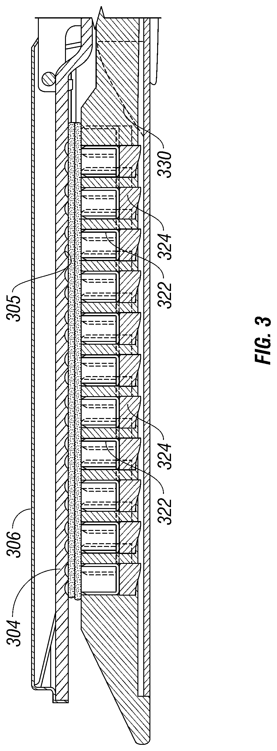
FIG. 1 is a perspective view of a powered surgical instrument according to an embodiment of the present disclosure;
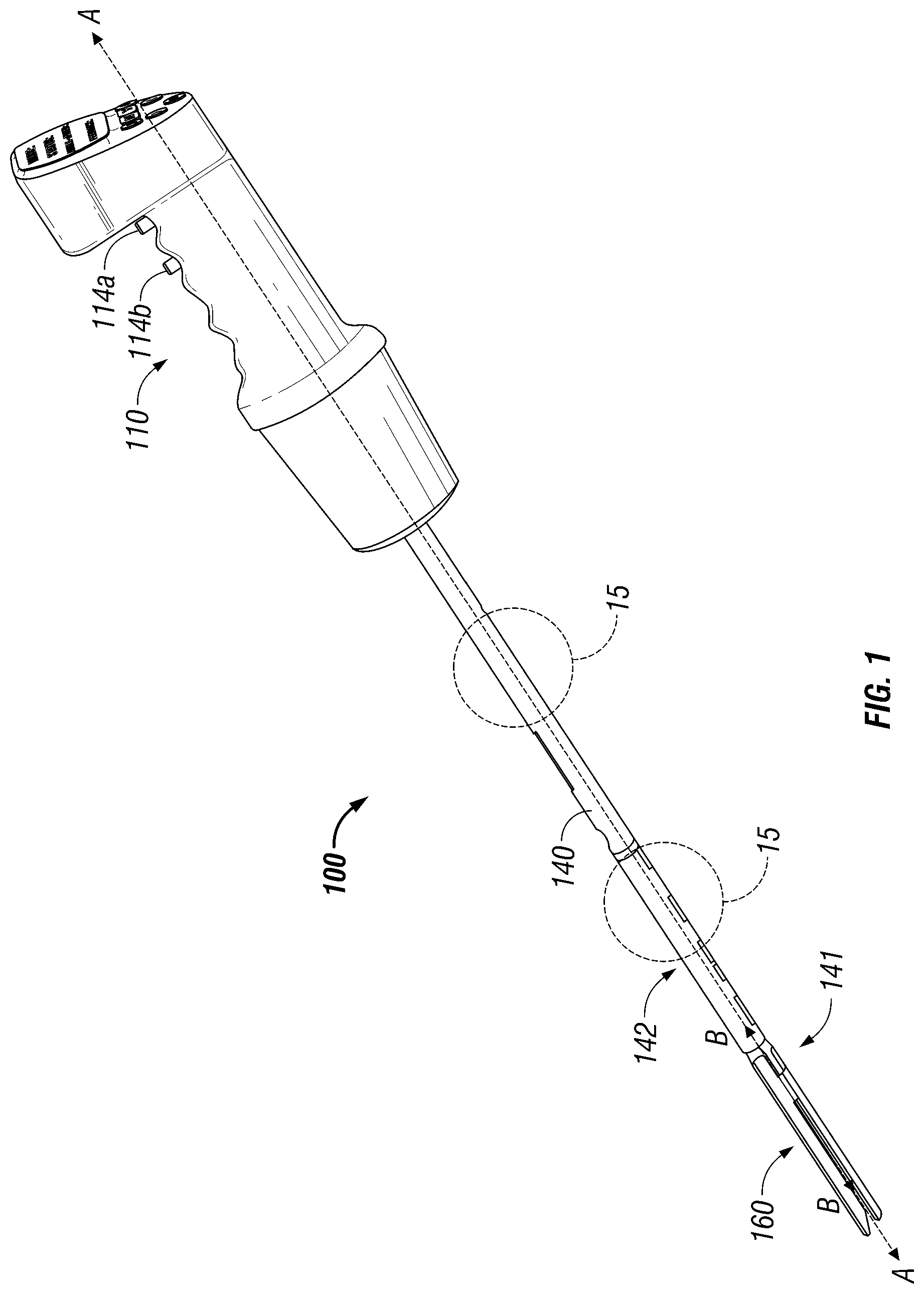
FIG. 2 is an exploded view of the staple cartridge and anvil or business head of the surgical instrument shown in FIG. 1;
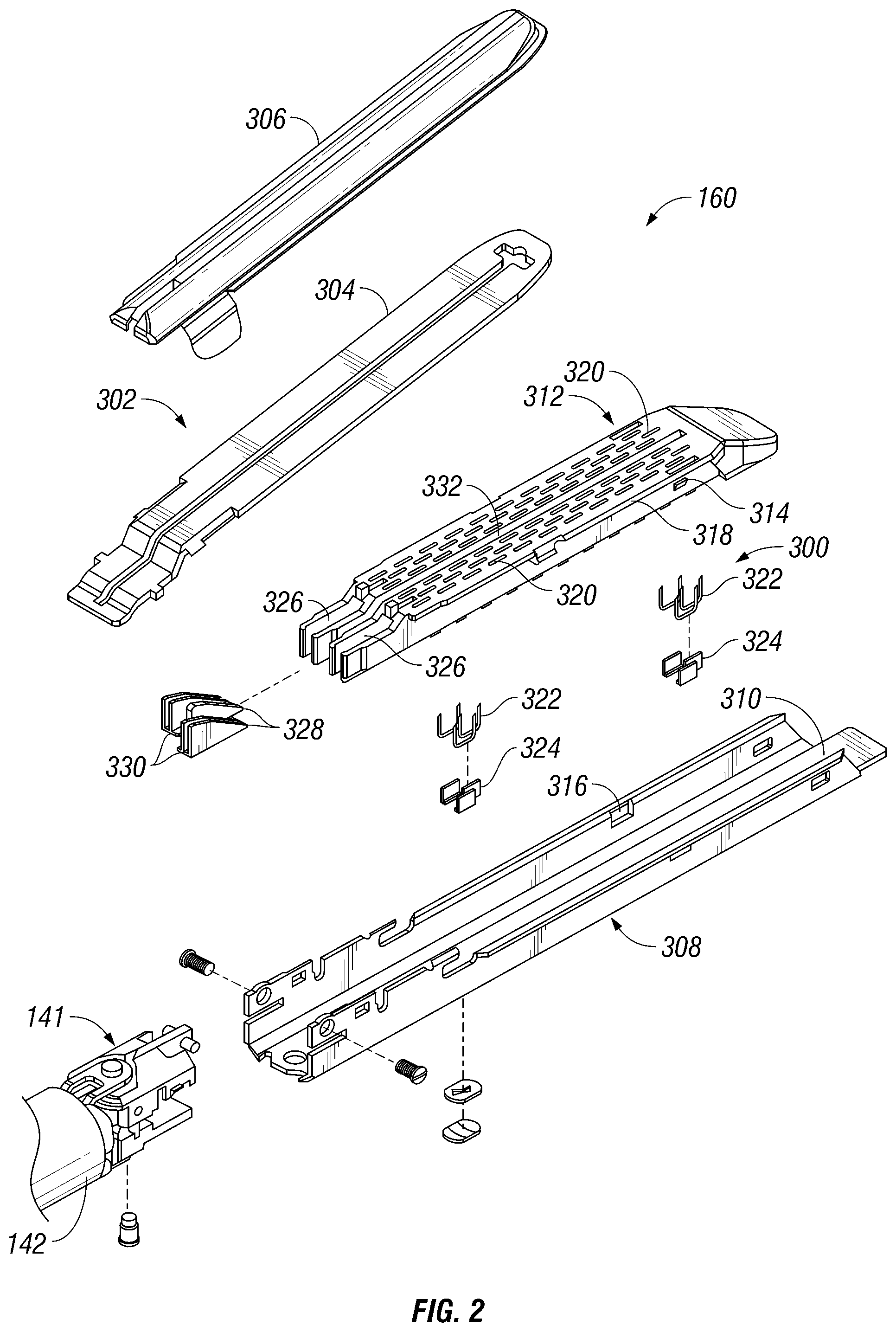
FIG. 3 is a side cross-sectional view of the staple cartridge and anvil or business head of the surgical instrument shown in FIG. 1;
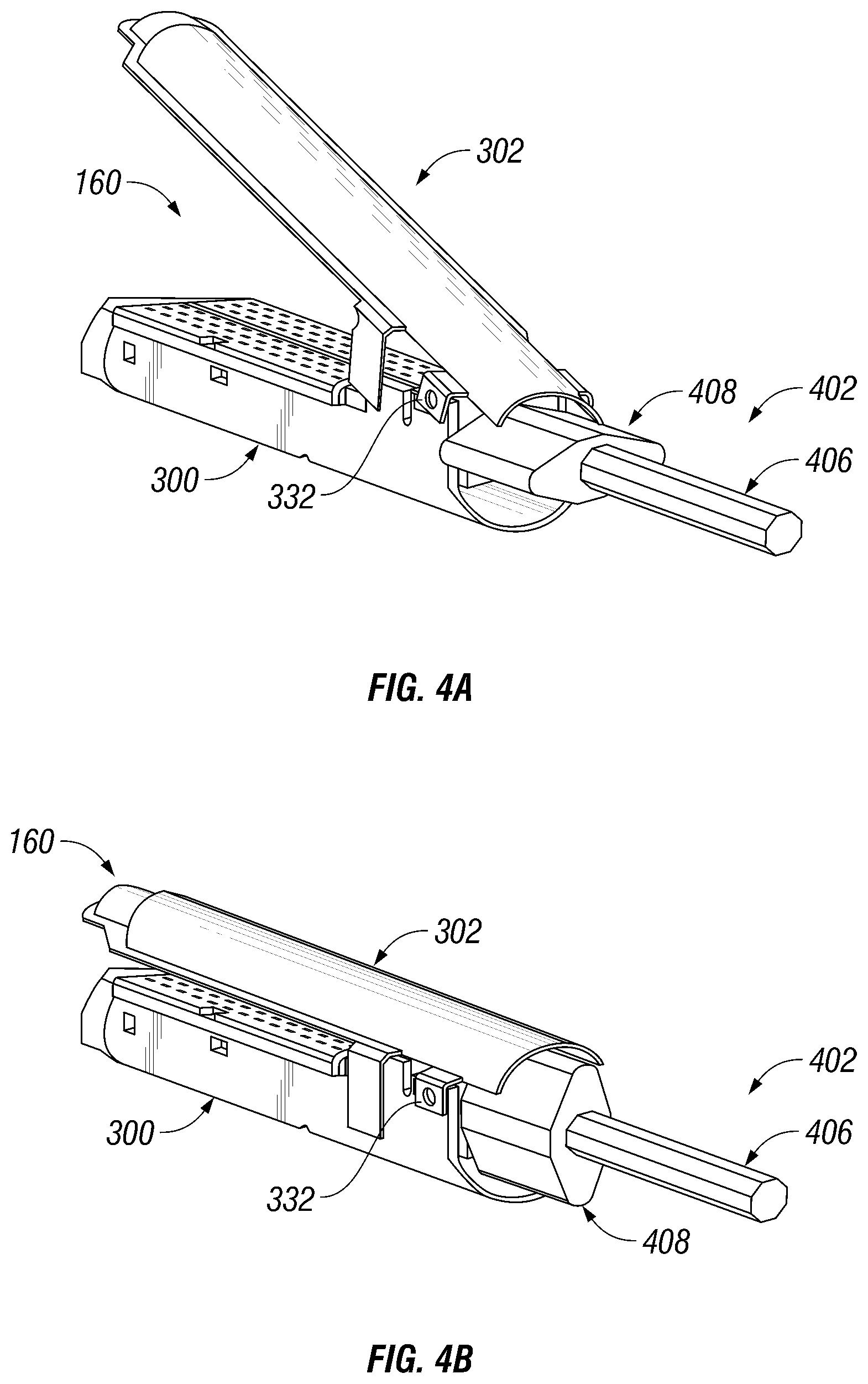
FIGS. 4A-B are perspective views of a shaped firing rod and cammed clamping of the stapler anvil in the open and closed positions;
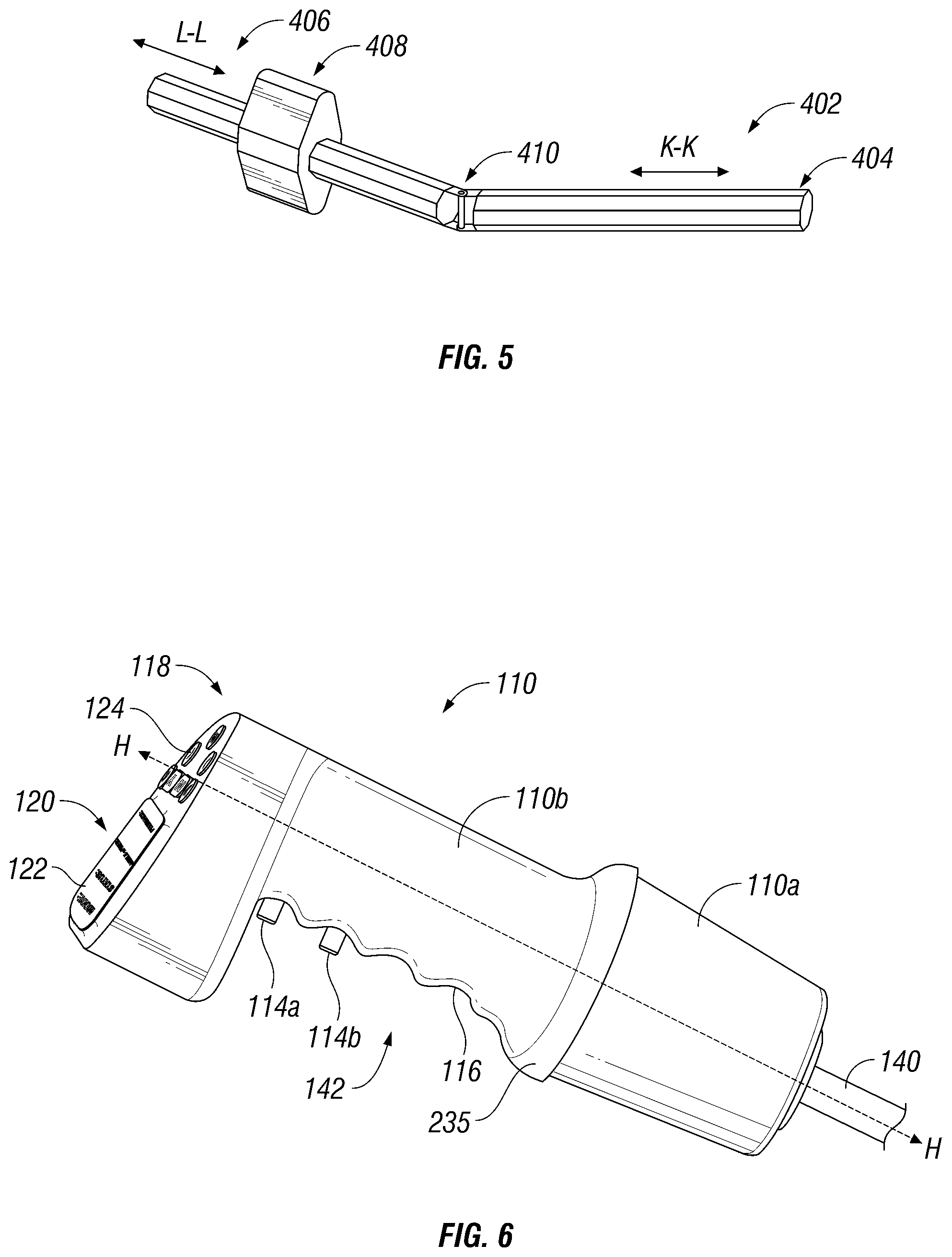
FIG. 5 is a perspective view of the cam and the shaped firing rod of the surgical instrument of FIG. 1;
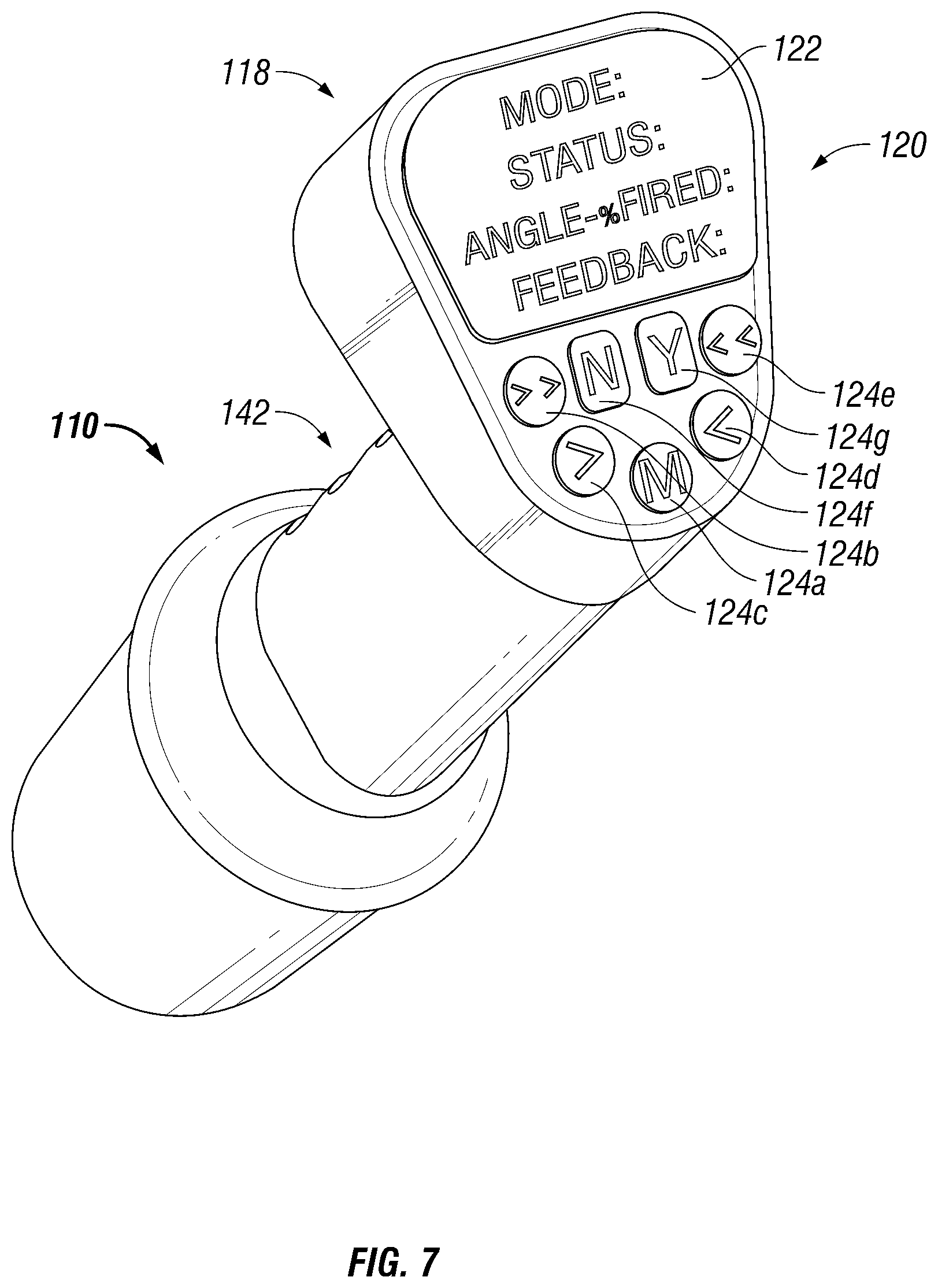
FIG. 6 is an enlarged perspective view of a handle of the powered surgical instrument of FIG. 1;
FIG. 7 is an enlarged perspective view of a user interface of the powered surgical instrument of FIG. 1;
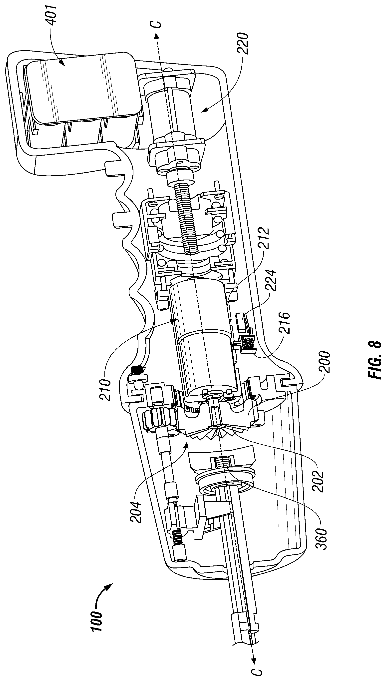
FIG. 8 is a perspective view of internal components of the powered surgical instrument of FIG. 1;
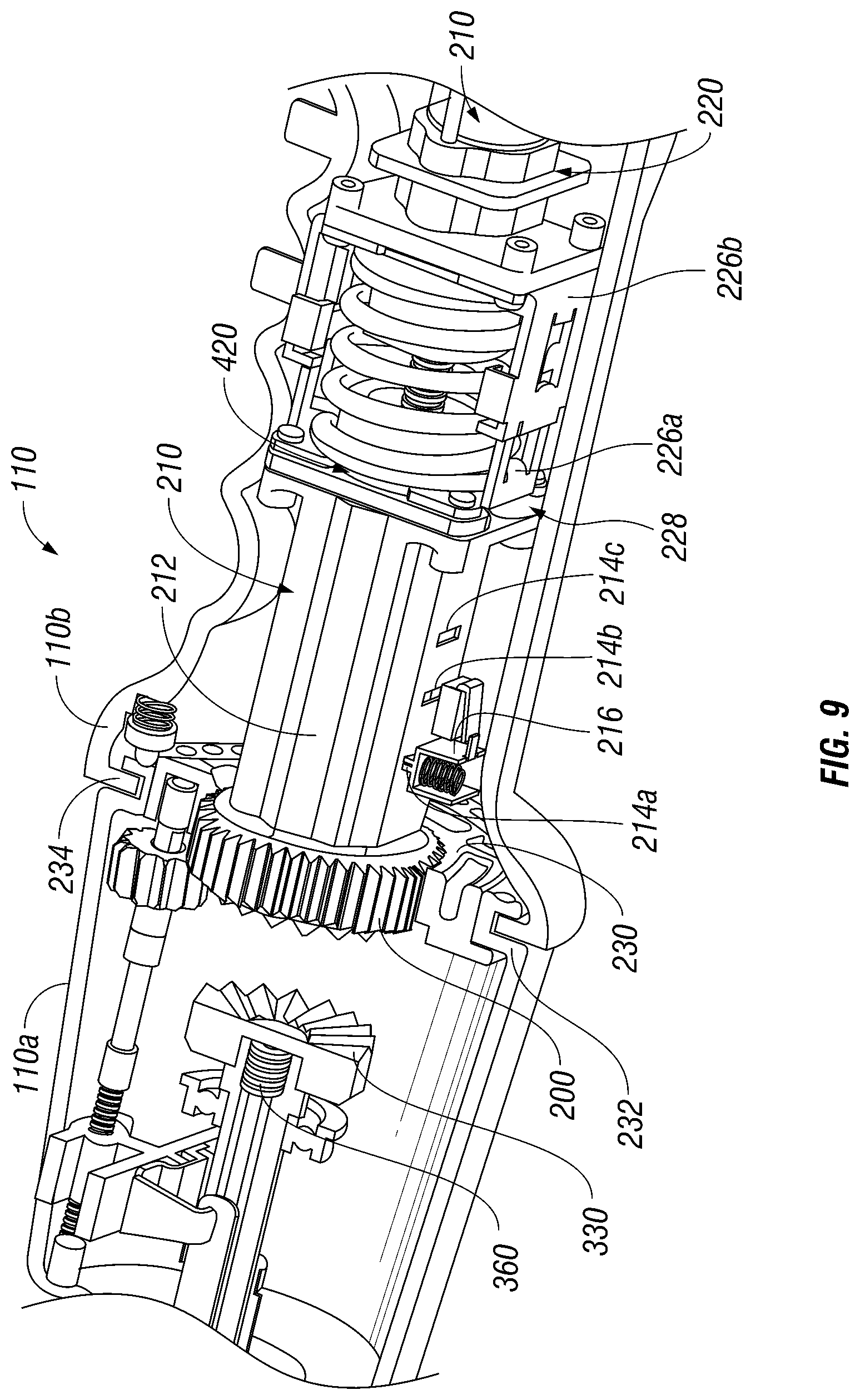
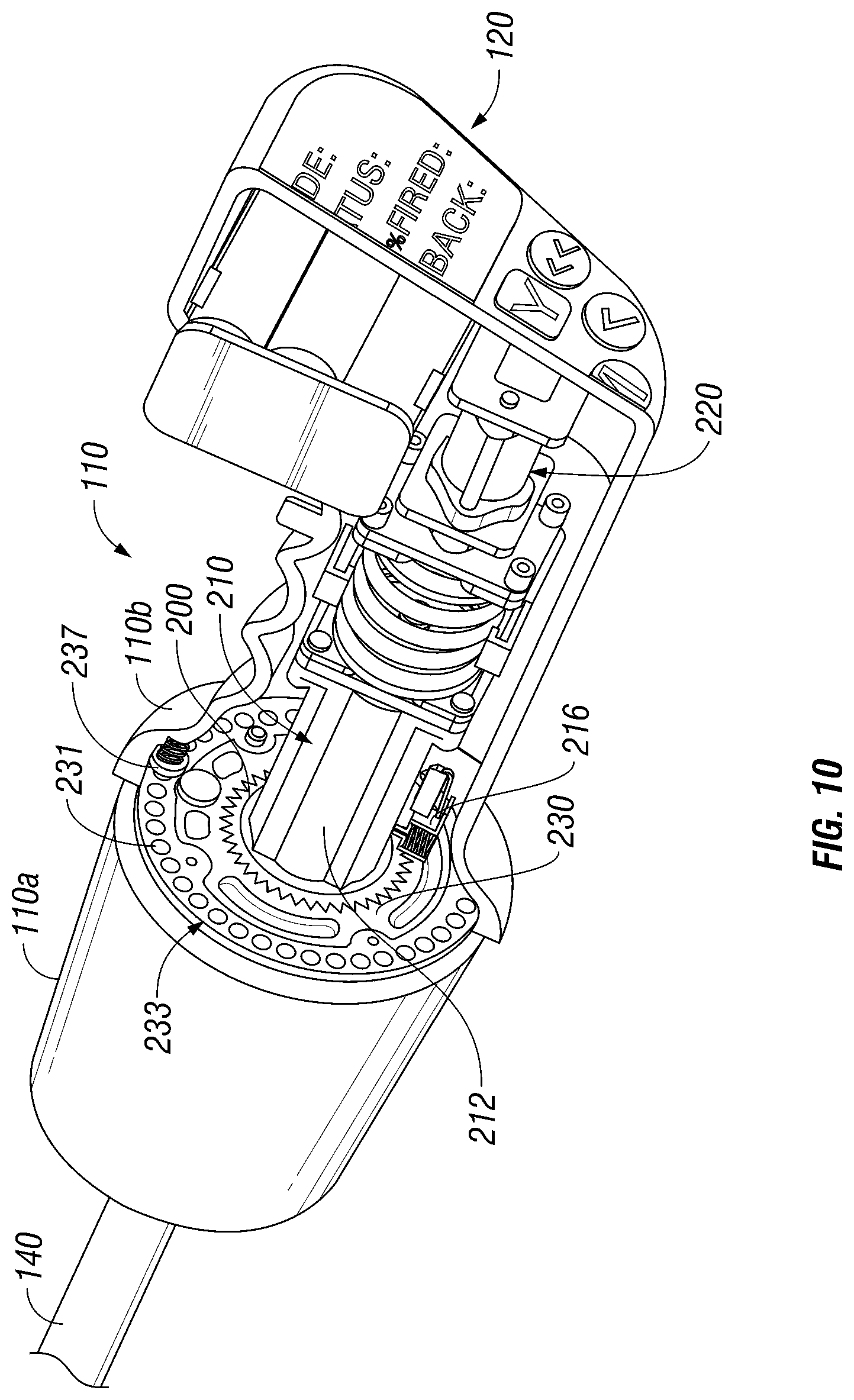
FIGS. 9 and 10 are perspective views of the internal components of the powered surgical instrument of FIG. 1 disposed in a first position, powered rotation;
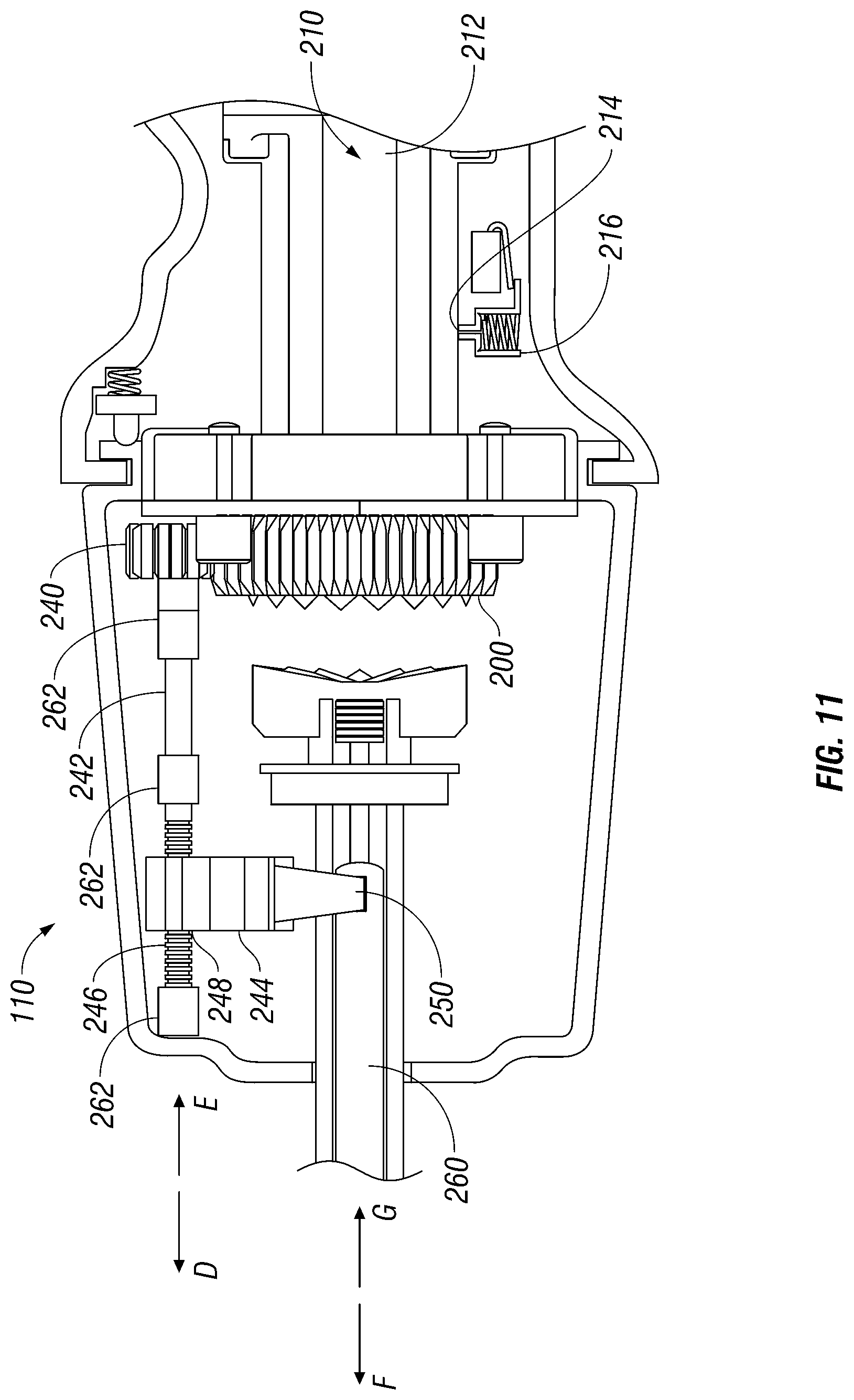
FIG. 11 is a side view of the internal components of the powered surgical instrument of FIG. 1 disposed in a second position, powered articulation;
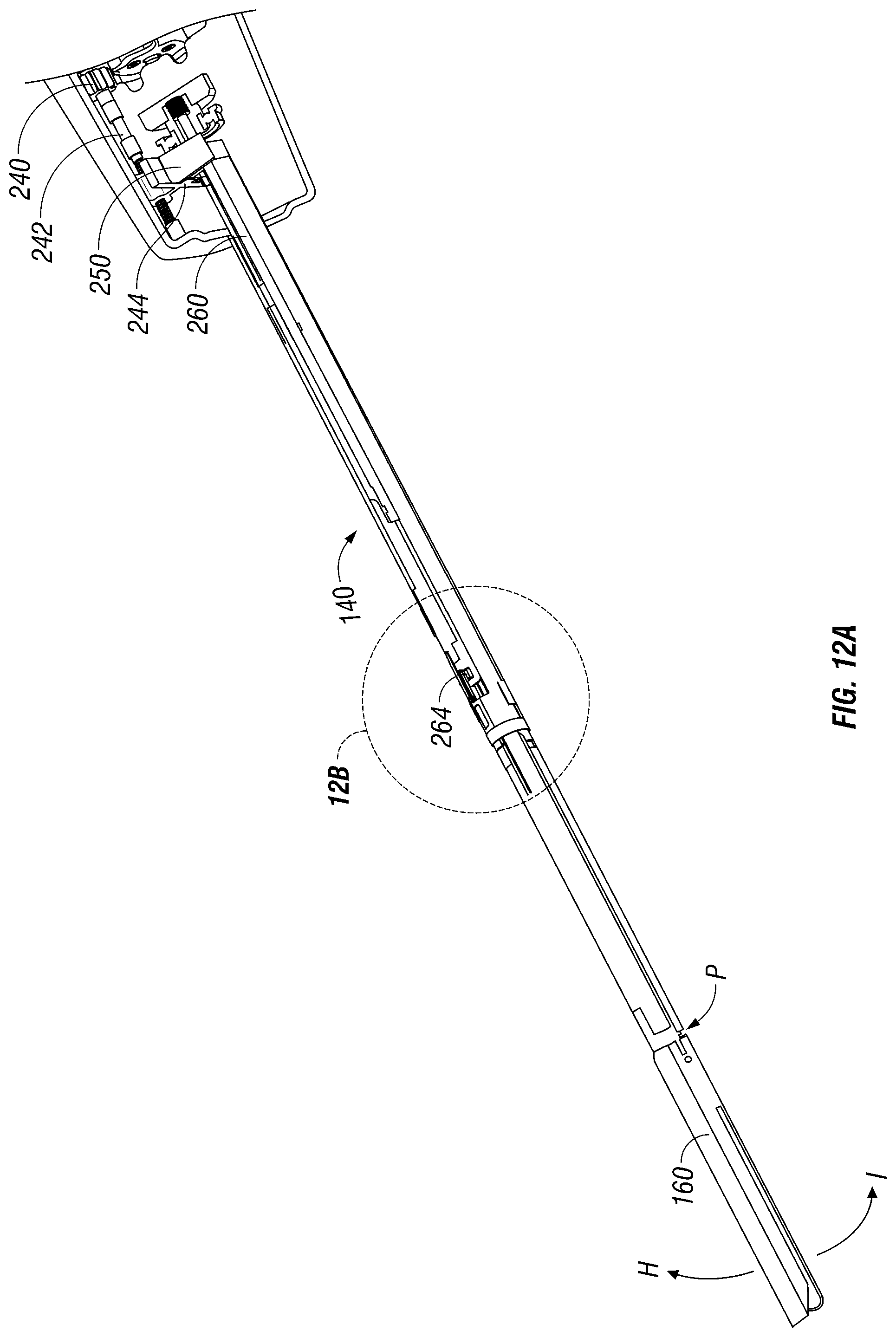
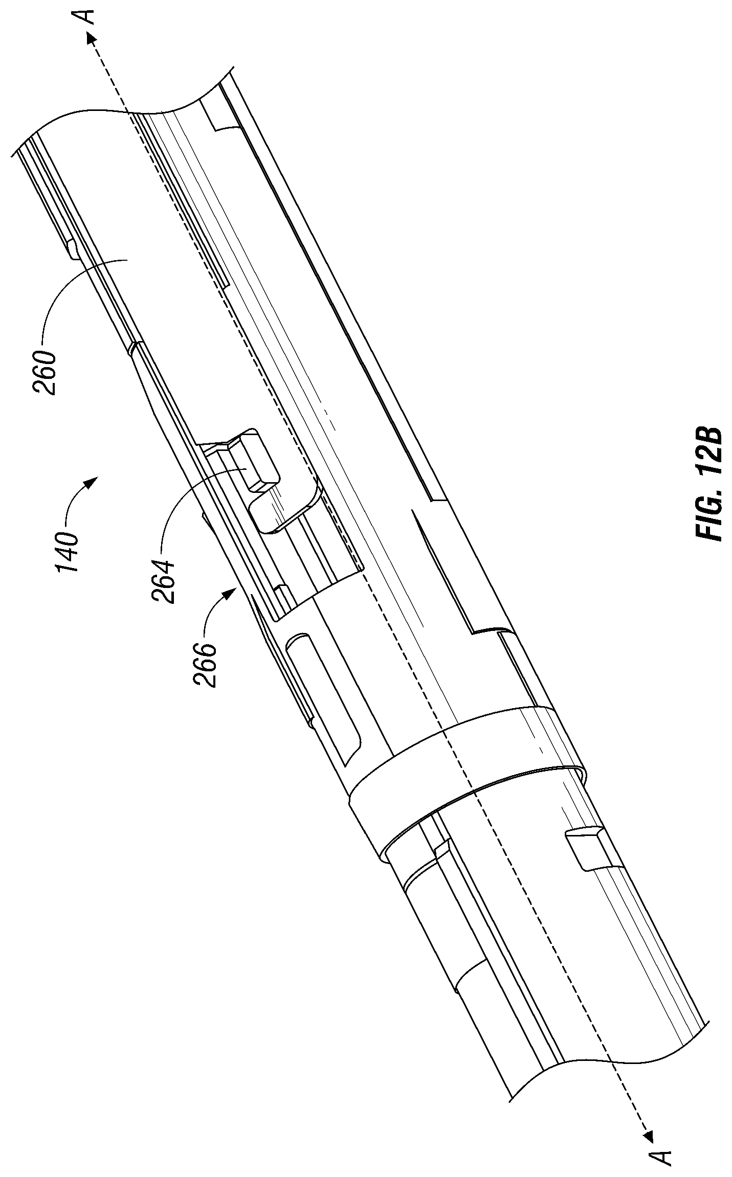
FIG. 12A is a perspective view including an endoscopic portion of the powered surgical instrument of FIG. 1 according to an embodiment of the present disclosure;
FIG. 12B is an enlarged perspective view of the portion of the powered surgical instrument indicated in FIG. 12A;
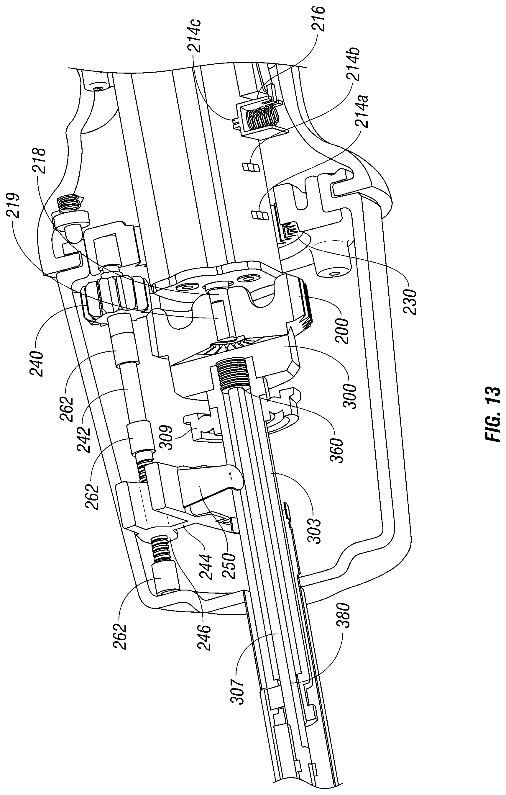
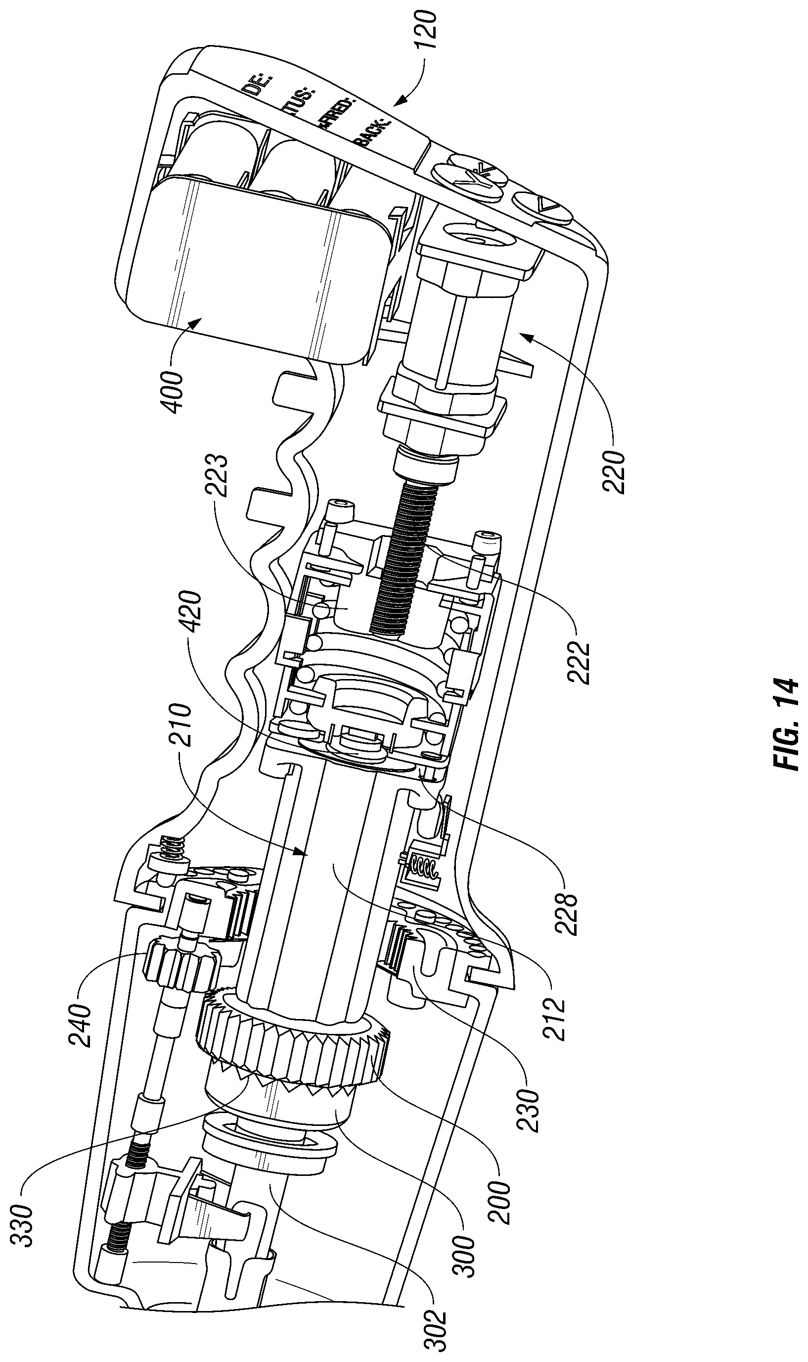
FIGS. 13-14 are perspective view of the internal components of the powered surgical instrument of FIG. 1 disposed in a third position, fire, clamp, grasp, retraction; and
FIGS. 15A-B are perspective views of articulating shaft of the distal portion of the powered surgical instrument of FIG. 1.
DETAILED DESCRIPTION OF EMBODIMENTS
Embodiments of the presently disclosed powered surgical instrument are now described in detail with reference to the drawings, in which like reference numerals designate identical or corresponding elements in each of the several views. As used herein the term "distal" refers to that portion of the powered surgical instrument, or component thereof, farther from the user while the term "proximal" refers to that portion of the powered surgical instrument or component thereof, closer to the user.
A powered surgical instrument, e.g., a surgical stapler, in accordance with the present disclosure is referred to in the figures as reference numeral 100. Referring initially to FIG. 1, powered surgical instrument 100 includes a housing 110, an endoscopic portion 140 defining a longitudinal axis A-A extending therethrough, and an end effector 160, defining a longitudinal axis B-B (illustrated substantially aligned with axis A-A in FIG. 1) extending therethrough. Endoscopic portion 140 extends distally from housing 110 and end effector 160 is disposed adjacent a distal portion 142 of endoscopic portion 140.
It is envisioned that end effector 160 is reusable and is configured to accept a staple cartridge and/or is part of a disposable loading unit. Further details of a disposable loading unit are described in detail in commonly-owned U.S. Pat. No. 6,241,139 to Miliman, the entire contents of which are hereby incorporated by reference herein.
The end effector 160 is coupled to the endoscopic portion 140 via a mounting assembly 141. The end effector 160 may be any end effector used in linear stapling devices, such as ENDO GIA.TM., GIA.TM., TA.TM., ENDO TA.TM., EEA.TM. staplers sold by U.S. Surgical Corp, of Norwalk, Conn. Such end effectors may be coupled to endoscopic portion 140 of powered surgical instrument 100. Mounting assembly 141 is pivotally secured to the distal portion 142 and is fixedly secured to a proximal end of tool assembly 160. This allows for pivotal movement of mounting assembly 141 about an axis perpendicular to the longitudinal axis A-A. Pivotal movement occurs between a non-articulated position in which the longitudinal axis of tool assembly 160 is aligned with the longitudinal axis A-A and an articulated position in which the longitudinal axis B-B of the tool assembly 160 is disposed at an angle to the longitudinal axis A-A of endoscopic portion 140.
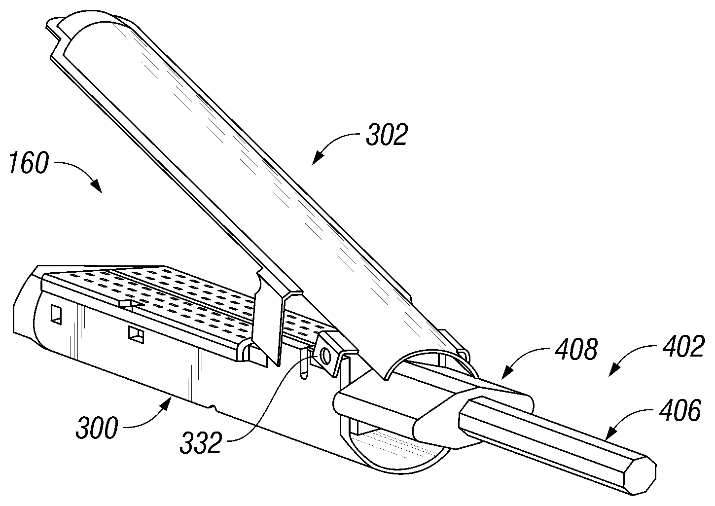
Referring to FIGS. 2 and 3, tool assembly 160 includes a cartridge assembly 300 (e.g., first jaw of the tool assembly) and an anvil assembly 302 (e.g., second of the tool assembly). Anvil assembly 302 includes an anvil portion 304 having a plurality of staple deforming concavities 305 (FIG. 3) and a cover plate 306 secured to a top surface of anvil portion 304. Cartridge assembly 300 includes carrier 308 which defines an elongated support channel 310 which is dimensioned and configured to receive staple cartridge 312. Corresponding tabs 314 and slots 316 formed along staple cartridge 312 and elongated support channel 310, respectively, function to retain staple cartridge 312 at a fixed location within support channel 310. A pair of support struts 318 formed on staple cartridge 312 is positioned to rest on side walls of carrier 308 to further stabilize staple cartridge 312 within support channel 310.
Staple cartridge 312 includes retention slots 320 for receiving a plurality of staples or fasteners 322 and pushers 324. A plurality of laterally spaced apart longitudinal slots 326 extends through staple cartridge 312 to accommodate upstanding cam wedges 328 of an actuation sled 330. A central longitudinal slot 332 extends along substantially the length of staple cartridge 312 to facilitate passage of a knife blade (not explicitly shown).
FIGS. 4A-B and 5 show a firing rod 402 for articulation and actuation of the tool assembly 160. The firing rod 402 includes a proximal shaft 404 which extends the length of the endoscopic portion 140 and the distal portion 142 and a distal shaft 406 which is disposed within the tool assembly 160. The proximal shaft 404 and the distal shaft 406 are pivotally linked via a pivot member 410 which passes through bores (not explicitly shown) within the distal end of the proximal shaft 404 and the proximal end of the distal shaft 406. Pivotal movement occurs between a non-articulated position in which the longitudinal axis of distal shaft 406 is aligned with the longitudinal axis K-K and an articulated position in which the longitudinal axis L-L of the tool distal shaft 406 is disposed at an angle to the longitudinal axis K-K of proximal shaft 404. The firing rod 402 may be formed from a rigid and/or flexible material. Forming the firing rod 402 from a flexible material obviates the need for pivot member 410 as the proximal shaft 404 can pivot with respect to the distal shaft 406 by nature of the flexibility of the material. It is envisioned that other pivoting mechanisms may be used, such as plastic or rubber bands interconnecting the proximal and distal portions 404 and 406.
The proximal shaft 404 and the distal shaft 406 of the firing rod 402 incorporate a plurality of surface features or shapes along the length thereof. In embodiments, the firing rod 402 has a generally cylindrical structure with a non-circular cross-section (e.g., hexagonal, octagonal, star-shaped, oval, etc.) It is also envisioned the firing rod 402 may include one or more curved shapes (e.g., helix, screw, etc.) These structures allow for gripping of the firing rod 402 and rotation thereof to actuate the tool assembly 160.
The firing rod 402 is disposed within a passage (not explicitly shown) of the endoscopic portion 140 and the distal portion 142, the passage has the same cross-sectional profile as the firing rod 402 such that the firing rod 402 is in mechanical cooperation with the passage but can simultaneously freely slide therein. This is especially useful if the firing rod 402 is formed from a flexible material since this prevents deformation of the firing rod 402 within the passage.
The firing rod 402 is configured for opening and closing of the anvil assembly 302 as well as pushing actuation sled 330 through longitudinal slots 326 of staple cartridge 312 to advance cam wedges 328 into sequential contact with pushers 324 to staple tissue. The firing rod 402 is configured to be selectively moved between a plurality of positions. In certain embodiments, the firing rod 402 is moved between at least two positions. The first position, illustrated in FIG. 4A, enables opening and closing of the anvil assembly 302 via rotation of the firing rod 402 about longitudinal axis K-K; the second position, illustrated in FIG. 4B, enables advancement of pushers 324 to push fasteners 322 through tissue.
In FIG. 4A the firing rod 402 is shown in the first position. The distal shaft 406 of the firing rod 402 includes a cam member 408, which is shown as a dual cam, disposed thereon. In the first position, the cam member 408 is positioned in a plane perpendicular to the longitudinal axis L-L at the distal end of the anvil assembly 302. During operation, the firing rod 402 is rotated, which causes rotation of the cam member 408. As the cam member 408 is rotated, the proximal end of the anvil assembly 302 is pushed upwards by the perpendicular displacement of the cam member 408 thereby closing the anvil assembly 302 against the cartridge assembly 300 (FIG. 4B).
The anvil assembly 302 is pivotally coupled to the cartridge assembly via tabs 332 which extend downwards therefrom. The tabs 332 fit into corresponding slots (not explicitly shown) to provide a hinge point for the anvil assembly 332 to pivot thereabout. This allows the anvil assembly 302 to pivot with respect to the cartridge assembly 300. As the firing rod 408 is rotated further the anvil assembly 302 reverts to open position via one or more biasing members (e.g., springs) pushing upwards on the opposite side of the tabs 332.
Various types of cams may be used to open and close the anvil assembly 302, such as single cams, or multi-cams. Other cam shapes may also be utilized which have a less aggressive angle utilizing full 360.degree. of rotation allowing the anvil assembly 302 to reach full displacement at a more gradual rate. Angle of rotation of the firing rod 402 varies with the type of cam being used, such as for the cam member 408, the firing rod 402 is rotated 90.degree. in order to actuate the anvil assembly 302. In other words, the cam member 402 allows for maximum displacement of the anvil assembly 302 under 90.degree.. It is also envisioned that the firing rod 402 may be rotated in either direction, clockwise or counterclockwise, to actuate the anvil assembly 302.
While in the first position the firing rod 402 is prevented from longitudinal movement in the distal direction by the proximal end of the cartridge assembly 300 and the cam member 408. The walls of the support channel 310 act as a stop member when the firing rod 402 is moved in the distal direction. Once the firing rod 402 is rotated into second position as shown in FIG. 4B, the firing rod 402 can be advanced distally to push the actuation sled 330 through the staple cartridge 312 since the firing rod 402 is no longer stopped by the distal end of the cartridge assembly. The firing rod 402 is movable through the cam member 408, the interface between an aperture through the cam member 408 and the firing rod 402 being shaped to allow a telescoping movement, but also shaped so that the cam member 408 and firing rod 402 rotate together. For example, the cam member 408 and firing rod 402 have a hexagonal shaped interface as shown in FIGS. 4A and 4B. Other shapes, such as helical, star shaped, splined, oval, slotted, and octagonal, can be used.
During operation of surgical stapler, the firing rod 402 abuts actuation sled 330 and pushes actuation sled 330 through longitudinal slots 326 of staple cartridge 312 to advance cam wedges 328 of sled 330 into sequential contact with pushers 324. Pushers 324 translate vertically along cam wedges 328 within fastener retention slots 320 and urge fasteners 322 from retention slots 320 into staple deforming cavities 304 (FIG. 4) of the anvil assembly 302.
With reference to FIGS. 6 and 7, an enlarged view of housing 110 is illustrated according to an embodiment of the present disclosure. In the illustrated embodiment, housing 110 includes a handle portion 110b having two buttons 114a and 114b. Handle portion 110b, which defines a handle axis H-H, is shown having indentations 116 that correspond to fingers of a user. Each button 114a and 114b is shown as being disposed on an indentation 116 to facilitate its depression by a user's finger.
A proximal area 118 of housing 110 includes a user interface 120. In the illustrated embodiment, user interface 120 includes a screen 122 and at least one switch 124 (seven switches 124a-124g are shown). Screen 122 displays readable information thereon, including status information of powered surgical instrument 100 in an embodiment.
FIG. 7 shows user interface 120 including screen 122 and seven switches 124a-124g. In the illustrated embodiment, user interface displays the "mode" (e.g., rotation, articulation or actuation), which may be communicated to user interface 120 via shift sensor 224, "status" (e.g., angle of articulation, speed of rotation, or type of actuation) and "feedback," such as whether staples have been fired. Switch 124a is shown having an "M," standing for mode, which may be used to position drive gear 200 via shift motor 220 for selecting between rotation, articulation, grasping, clamping and firing. It is also envisioned that switch 124a can be used to let a user input different tissue types, and various sizes and lengths of staple cartridges.
Switches 124b-124e are shown with arrows thereon and may be used for selecting the direction, speed and/or torque at which drive gear 200 is rotated by drive motor 210. It is also envisioned that at least one switch 124 can be used for selecting an emergency mode that overrides various settings. Further, switches 124f and 124g are illustrated having an "N" and a "Y" thereon. It is envisioned that switches 124f and 124g may be used for helping a user navigate user interface menus and select various setting of powered surgical instrument 100. The indicia on switches 124a-124g and their respective functions are not limited by what is shown in the accompanying figures, as deviations therefrom are contemplated and within the scope of the present disclosure. Additionally, and with reference to FIGS. 1 and 6, buttons 114a and 114b may be used for starting and/or stopping movement of drive motor 210 and/or shift motor 220 and the like.
FIGS. 8-14 illustrate various internal components of powered surgical instrument 100, including a drive gear 200, a drive motor 210 and a shift motor 220. Power is provided via a battery pack 401 (or fuel cell assembly). Other power-supplying means are also contemplated (e.g., electrical transformers coupled to conventional electrical power supplies).
As shown in FIG. 8, the drive gear 200, the drive motor 210 and the battery pack 401 are disposed within the housing 110, specifically a proximal housing portion 110b. It is envisioned that these components may also be located within or closer to a distal housing portion 110a. The primary or a secondary motor, transmission, and/or the batteries may be disposed in the endoscopic portion 140.
Drive gear 200 is rotatable about a drive gear axis C-C extending therethrough (FIG. 8) and is selectively movable along drive gear axis C-C. Drive motor 210 is disposed in mechanical cooperation with drive gear 200 and is configured to rotate drive gear 200 about drive gear axis C-C. Shift motor 220 is disposed in mechanical cooperation via the drive motor 210 with drive gear 200 and is configured to translate drive gear 200 axially along drive gear axis C-C.
Shift motor 220 is configured to selectively move drive gear 200 between a plurality of positions. In embodiments, the drive gear 200 is moved between three positions. The first position, illustrated in FIGS. 9 and 10, enables rotation of end effector 160; the second position, illustrated in FIG. 11, enables articulation of end effector 160; and the third position, illustrated in FIGS. 13-14, enables actuation of powered surgical instrument 100.
In the embodiment illustrated in FIG. 9, shift motor 220 is shown including a two-part housing 226. Each part 226a and 226b of two-part housing 226 are slidably engaged with each other. It is envisioned that part 226a is rigidly secured to a drive motor casing 212, while part 226b is affixed to drive motor 210 and is translatable within housing 110. Additionally, a wiring slot 228 may be included to allow for wires (not explicitly shown) to pass from transducer 420 towards user interface 120, for example.
A cut away of the drive motor casing 212, at least partially surrounding drive motor 210, is illustrated in FIGS. 8-11. Drive motor casing 212 includes slots 214a, 214b and 214c therein. Each slot 214 is configured to mate with a position lock 216 to maintain drive gear 210 in a desired position. In FIG. 9, position lock 216 is shown mated with slot 214a--corresponding to drive gear 200 being in its first position. In FIG. 11, position lock 216 is shown mated with slot 214b--corresponding to drive gear 200 being in its second position. FIGS. 13 and 14 illustrate position lock 216 mated with slot 214c--corresponding to drive gear 200 being in its third position. Position lock 216, in the illustrated embodiments, is spring-loaded and biased against the drive motor casing 212, which maintains drive motor 210 is a desired position.
In the illustrated embodiments, shift motor 220 is located proximally of drive motor 210 and is configured to translate drive motor 210 along drive gear axis C-C between its first, second and third positions. Referring to FIG. 14, shift motor 220 is illustrated being driven by a shift screw 222 in conjunction with an internally-threaded screw housing 223, in accordance with a disclosed embodiment. It is further disclosed that a shift sensor 224 (See FIG. 8) (e.g., micro switch or optical/ferromagnetic proximity sensor activate by position lock 216), disposed adjacent position lock 216, electrically communicates with at least one switch 124 to start or stop shift motor 220 and/or provides feedback relating to the position of drive motor 210 (e.g., position of drive motor 210, such as "rotation," is displayed on screen 122 of user interface 120).
With reference to FIGS. 9 and 10, the first position of drive gear 200 is illustrated. Ring gear 230 is disposed within housing 110, wherein rotation of ring gear 230 causes rotation of endoscopic portion 140, end effector 160 and a distal housing portion 110a. Distal housing portion 110a is disposed distally of a proximal housing portion 110b. The housing portion 110a includes a guide channel 232 which is peripherally disposed therein and is configured to interface with a corresponding flange 234 which is peripherally disposed within the proximal housing portion 110b. In particular, the flange 234 is configured to slidably rotate within the guide channel 232 thereby allow for rotation of the housing portion 110a with respect to proximal housing portion 110b. In
D00000
D00001
D00002
D00003
D00004
D00005
D00006
D00007
D00008
D00009
D00010
D00011
D00012
D00013
D00014
D00015
XML
uspto.report is an independent third-party trademark research tool that is not affiliated, endorsed, or sponsored by the United States Patent and Trademark Office (USPTO) or any other governmental organization. The information provided by uspto.report is based on publicly available data at the time of writing and is intended for informational purposes only.
While we strive to provide accurate and up-to-date information, we do not guarantee the accuracy, completeness, reliability, or suitability of the information displayed on this site. The use of this site is at your own risk. Any reliance you place on such information is therefore strictly at your own risk.
All official trademark data, including owner information, should be verified by visiting the official USPTO website at www.uspto.gov. This site is not intended to replace professional legal advice and should not be used as a substitute for consulting with a legal professional who is knowledgeable about trademark law.