Method and system for core-shell catalyst processing
Shao , et al. Ja
U.S. patent number 10,541,425 [Application Number 14/904,679] was granted by the patent office on 2020-01-21 for method and system for core-shell catalyst processing. This patent grant is currently assigned to AUDI AG. The grantee listed for this patent is Audi AG. Invention is credited to Jonathan H. Odell, Minhua Shao, John W. Weidner.


| United States Patent | 10,541,425 |
| Shao , et al. | January 21, 2020 |
Method and system for core-shell catalyst processing
Abstract
According to an embodiment, a method of processing a material for a catalyst includes establishing an electrical potential on a porous electrode. Core particles are directed through the porous electrode. A layer of metal is deposited on the core particles as the particles pass through the porous electrode. According to an embodiment, an example assembly for processing a material for a catalyst includes a housing that establishes a path for particles to move through the housing. A porous electrode is situated within the housing for permitting core particles to move through the porous electrode. A layer of metal can be deposited on the core particles as the particles pass through the porous electrode.
| Inventors: | Shao; Minhua (Farmington, CT), Weidner; John W. (Elgin, SC), Odell; Jonathan H. (Agawam, MA) | ||||||||||
|---|---|---|---|---|---|---|---|---|---|---|---|
| Applicant: |
|
||||||||||
| Assignee: | AUDI AG (Ingolstadt,
DE) |
||||||||||
| Family ID: | 52346598 | ||||||||||
| Appl. No.: | 14/904,679 | ||||||||||
| Filed: | July 19, 2013 | ||||||||||
| PCT Filed: | July 19, 2013 | ||||||||||
| PCT No.: | PCT/US2013/051200 | ||||||||||
| 371(c)(1),(2),(4) Date: | January 12, 2016 | ||||||||||
| PCT Pub. No.: | WO2015/009311 | ||||||||||
| PCT Pub. Date: | January 22, 2015 |
Prior Publication Data
| Document Identifier | Publication Date | |
|---|---|---|
| US 20160172685 A1 | Jun 16, 2016 | |
| Current U.S. Class: | 1/1 |
| Current CPC Class: | H01M 4/9075 (20130101); H01M 4/926 (20130101); C25D 17/12 (20130101); H01M 4/921 (20130101); B22F 1/0018 (20130101); C25D 7/006 (20130101); C23C 18/54 (20130101); H01M 4/8657 (20130101); H01M 4/8825 (20130101); C25D 17/16 (20130101); H01M 4/92 (20130101); B22F 1/025 (20130101); H01M 4/8853 (20130101); B82Y 30/00 (20130101) |
| Current International Class: | H01M 4/88 (20060101); H01M 4/92 (20060101); H01M 4/90 (20060101) |
References Cited [Referenced By]
U.S. Patent Documents
| 9484582 | November 2016 | Marzullo et al. |
| 9610566 | April 2017 | Shao et al. |
| 2003/0017378 | January 2003 | Ruth et al. |
| 2006/0135359 | June 2006 | Adzic et al. |
| 2007/0129247 | June 2007 | Chigapov et al. |
| 2008/0081017 | April 2008 | Zhou et al. |
| 2008/0200741 | August 2008 | Kowaleski |
| 2012/0010069 | January 2012 | Takehiro et al. |
| 2012/0245017 | September 2012 | Adzic et al. |
| 2012/0258854 | October 2012 | Kawamura et al. |
| 2012/0316060 | December 2012 | Shao et al. |
| 2012/0329642 | December 2012 | Shao |
| 2013/0034803 | February 2013 | Adzic et al. |
| 2013/0324394 | December 2013 | Shao et al. |
| 2013/0340915 | December 2013 | Shao |
| 0 171 478 | Feb 1986 | EP | |||
| 2 308 596 | Apr 2011 | EP | |||
| 63-162896 | Jul 1988 | JP | |||
| 2002-069689 | Mar 2002 | JP | |||
| 2008-297574 | Dec 2008 | JP | |||
| 2009-504914 | Feb 2009 | JP | |||
| 2014-128756 | Jul 2014 | JP | |||
| 2011/119818 | Sep 2011 | WO | |||
| WO 2012/115624 | Aug 2012 | WO | |||
| 2013/024305 | Feb 2013 | WO | |||
Attorney, Agent or Firm: Seed Intellectual Property Law Group LLP
Claims
We claim:
1. A method of processing a material for a catalyst, comprising: establishing an electrical potential on a porous electrode; directing core particles through the porous electrode; depositing a layer of metal on the core particles as the particles pass through the porous electrode; mixing the core particles having the deposited layer of metal with a solution including K.sub.2PtCl.sub.4, citric acid and citrate; and replacing the deposited layer of metal with platinum to thereby establish a platinum monolayer on the core particles, the concentration of citric acid and citrate together is greater than 10 times the concentration of the K.sub.2PtCl.sub.4 in the solution; the porous electrode has a length along a direction that the core particles travel as the core particles pass through the porous electrode; and the length is selected to facilitate depositing a uniform monolayer of the metal on the core particles.
2. The method of claim 1, wherein contact between the core particles and the porous electrode facilitates the depositing.
3. The method of claim 1, wherein the core particles comprise palladium; and the layer of metal comprises copper.
4. The method of claim 3, wherein the core particles comprise palladium nanoparticles supported on carbon particles.
5. The method of claim 1, wherein the layer of metal comprises a monolayer of copper.
6. The method of claim 1, wherein the porous electrode comprises carbon.
7. An assembly for processing a material for a catalyst, the assembly comprising: a housing that establishes a path for core particles to move through the housing; a porous electrode situated within the housing for permitting core particles to move through the porous electrode whereby a layer of metal can be deposited on the core particles as the core particles pass through the porous electrode; and a replacement chamber comprising a solution including K.sub.2PtCl.sub.4, citric acid and citrate, the replacement chamber providing a reservoir for mixing the core particles having a layer of metal deposited with the solution thereby replacing the deposited layer of metal with platinum to establish a platinum monolayer on the core particles, the concentration of citric acid and citrate together is greater than 10 times the concentration of the K.sub.2PtCl.sub.4 in the solution; the porous electrode has a length along a direction that the core particles travel as the core particles pass through the porous electrode; and the length is selected to facilitate depositing a uniform monolayer of the metal on the core particles.
8. The assembly of claim 7, wherein the core particles comprise palladium; and the layer of metal comprises copper.
9. The assembly of claim 8, wherein the core particles comprise palladium nanoparticles supported on carbon particles.
10. The assembly of claim 7, wherein the porous electrode comprises carbon.
11. The assembly of claim 7, wherein the metal layer comprises a monolayer of copper.
Description
BACKGROUND
Fuel cells are useful for producing electrical energy based on an electrochemical reaction. One of the challenges associated with implementing fuel cells on a large scale has been the expense typically associated with the fuel cell components. For example, catalyst layers typically include expensive materials such as platinum. There have been various proposals for reducing the amount of platinum required to reduce the cost associated with fuel cells.
One proposal has been to use core-shell catalysts including a noble metal core with a shell of platinum deposited on the core. Such core-shell catalyst are considered promising for low temperature fuel cells, for example. Synthesizing core-shell catalysts according to some proposals includes establishing a copper monolayer on a palladium (or other noble metal) core and subsequently displacing the copper with a monolayer of platinum. Some of the challenges associated with proposed techniques in this regard include avoiding platinum cluster formation during the deposition process to achieve a platinum monolayer having desired characteristics. The type of constraints required to control the platinum deposition process tend to limit the batch size and that may detract from any economic benefits associated with utilizing core-shell catalysts.
SUMMARY
According to an embodiment, a method of processing a material for a catalyst includes establishing an electrical potential on a porous electrode. Core particles are directed through the porous electrode. A layer of metal is deposited on the core particles as the particles pass through the porous electrode.
According to an embodiment, an example assembly for processing a material for a catalyst includes a housing that establishes a path for particles to move through the housing. A porous electrode is situated within the housing for permitting a dispersion of core particles to move through the porous electrode. A layer of metal can be deposited on the core particles as the particles pass through the porous electrode.
The various features and advantages of at least one disclosed embodiment will become apparent to those skilled in the art from the following detailed description. The drawings that accompany the detailed description can be briefly described as follows.
BRIEF DESCRIPTION OF THE DRAWINGS
FIG. 1 schematically illustrates a system configured for performing a method of processing a material for a catalyst according to an embodiment of this invention.
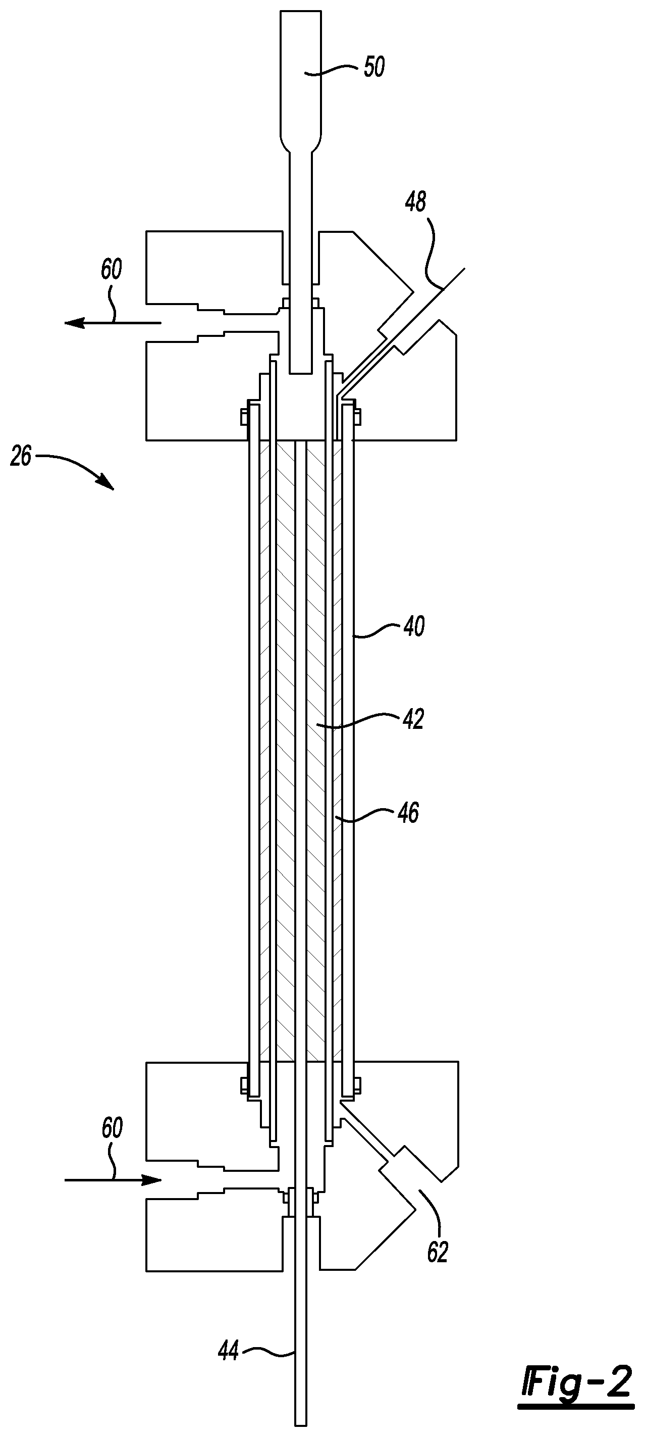
FIG. 2 schematically illustrates an example reactor including a porous electrode according to an embodiment of this invention.
DETAILED DESCRIPTION
FIG. 1 schematically illustrates a system 20 that is configured for performing a method of processing a material for a catalyst. The system 20 is useful for realizing core-shell catalysts that include a platinum monolayer over a shell of a noble metal, such as palladium. The system 20 includes a reservoir 22 that includes a solution of core particles, copper sulfate and hydrogen sulfate (CuSO.sub.4+H.sub.2SO.sub.4). The solution within the reservoir 22 also includes core particles of a selected noble metal, such as palladium. In one example, the solution within the reservoir 22 includes a concentration of 0.05 M copper sulfate and 0.05 M hydrogen sulfate.
In some examples, the core particles comprise palladium or a selected noble metal. In one embodiment, the core particles comprise palladium nanoparticles supported on carbon particles.
A pump 24 directs the solution from the reservoir 22 into a reactor 26 where a copper monolayer is deposited on the core particles. Once the copper monolayer has been deposited on the core particles they are directed to a replacement chamber 28 where the copper monolayer is replaced with a platinum monolayer.
The reaction for replacing the copper monolayer with the platinum monolayer in the illustrated example occurs in a generally known manner. For example, a solution provided at 30 includes K.sub.2PtCl.sub.4+H.sub.2SO.sub.4 plus an additive, such as citric acid and citrate. In one example, the K.sub.2PtCl.sub.4 has a concentration of 0.001 M, the H.sub.2SO.sub.4 has a concentration of 0.05 M and the additive concentration is more than ten times higher than that of K.sub.2PtCl.sub.4. The reaction within the replacement chamber 28 may be summarized as Cu+Pt.sup.2+=Cu.sup.2++Pt.
The reactor 26 is configured to facilitate a scaled-up process of achieving a platinum monolayer on a core-shell catalyst. As shown in FIG. 2, the reactor 26 includes a housing 40, such as a glass tube. A porous working electrode 42 is electrically charged and associated with an electrically conductive lead 44. The porous electrode 42 is situated within the housing 40. The porous electrode 42 comprises a carbon matrix or lattice structure in this example. Those skilled in the art who have the benefit of this description will realize how to configure a porous carbon matrix that allows a solution including the core particles to pass through the porous working electrode 42 as the solution moves through the reactor 26.
Another porous tube 46 is situated within the housing 40. The porous tube 46 serves as a counter electrode associated with an electrically conductive lead 48. A reference electrode 50 is provided in this example. The electrodes facilitate depositing a monolayer of copper on the core particles. As the solution including the core particles moves through the porous working electrode 42, contact between the porous carbon matrix and the particles provides the potential for depositing copper onto the particles. In one example, the core particles comprise carbon with palladium supported on the carbon. The solution including the core particles flows through the reactor 26 as schematically shown at 60. The porous electrode 42 has a length along the direction of flow through the reactor 26 that facilitates establishing a uniform monolayer of copper on the core articles.
The illustrated example includes a drain 62 to facilitate removing any fluid from the reactor 26 as may be required.
One feature of the porous working electrode 42 is that it facilitates achieving a copper monolayer on the core particles in large batch quantities. While previous proposed arrangements for plating catalyst core particles with a monolayer of copper may have yielded results measured in grams, the illustrated reactor 26 yields results measured in kilograms. In other words, the porous electrode reactor configuration makes it possible to increase production quantities by 1,000 times that which may have been expected using other copper deposition equipment or techniques.
The disclosed example reactor configuration enhances the economies associated with utilizing core-shell catalyst materials. The ability to realize large-scale production renders core-shell catalysts an even more promising substitute for pure platinum for manufacturing catalysts for use in fuel cells or other electrochemical-based energy producing devices.
The preceding description is illustrative rather than limiting in nature. Variations and modifications to the disclosed examples may become apparent to those skilled in the art that do not necessarily depart from the essence of the contribution to the art provided by the disclosed example. The scope of legal protection provided to the invention can only be determined by studying the following claims.
* * * * *
D00000
D00001
D00002
XML
uspto.report is an independent third-party trademark research tool that is not affiliated, endorsed, or sponsored by the United States Patent and Trademark Office (USPTO) or any other governmental organization. The information provided by uspto.report is based on publicly available data at the time of writing and is intended for informational purposes only.
While we strive to provide accurate and up-to-date information, we do not guarantee the accuracy, completeness, reliability, or suitability of the information displayed on this site. The use of this site is at your own risk. Any reliance you place on such information is therefore strictly at your own risk.
All official trademark data, including owner information, should be verified by visiting the official USPTO website at www.uspto.gov. This site is not intended to replace professional legal advice and should not be used as a substitute for consulting with a legal professional who is knowledgeable about trademark law.