Twenty-eight-cornered strengthening member for vehicles
Tyan , et al. Ja
U.S. patent number 10,538,271 [Application Number 16/279,377] was granted by the patent office on 2020-01-21 for twenty-eight-cornered strengthening member for vehicles. This patent grant is currently assigned to FORD GLOBAL TECHNOLOGIES, LLC. The grantee listed for this patent is FORD GLOBAL TECHNOLOGIES, LLC. Invention is credited to Yu-Kan Hu, Leonard Anthony Shaner, Tau Tyan.
View All Diagrams
| United States Patent | 10,538,271 |
| Tyan , et al. | January 21, 2020 |
Twenty-eight-cornered strengthening member for vehicles
Abstract
A vehicle includes a strengthening member having a cross section including twenty-eight corners. The cross section has twenty-eight sides arranged to create twenty internal angles and eight external angles.
| Inventors: | Tyan; Tau (Northville, MI), Hu; Yu-Kan (Ypsilanti, MI), Shaner; Leonard Anthony (New Baltimore, MI) | ||||||||||
|---|---|---|---|---|---|---|---|---|---|---|---|
| Applicant: |
|
||||||||||
| Assignee: | FORD GLOBAL TECHNOLOGIES, LLC
(Dearborn, MI) |
||||||||||
| Family ID: | 61241517 | ||||||||||
| Appl. No.: | 16/279,377 | ||||||||||
| Filed: | February 19, 2019 |
Prior Publication Data
| Document Identifier | Publication Date | |
|---|---|---|
| US 20190176892 A1 | Jun 13, 2019 | |
Related U.S. Patent Documents
| Application Number | Filing Date | Patent Number | Issue Date | ||
|---|---|---|---|---|---|
| 15251029 | Aug 30, 2016 | 10279842 | |||
| Current U.S. Class: | 1/1 |
| Current CPC Class: | B62D 25/00 (20130101); F16F 7/128 (20130101); F16F 7/12 (20130101); B62D 21/00 (20130101); F16F 7/124 (20130101) |
| Current International Class: | B62D 25/00 (20060101); B62D 21/00 (20060101); F16F 7/12 (20060101) |
| Field of Search: | ;296/193.01 |
References Cited [Referenced By]
U.S. Patent Documents
| 1951292 | March 1934 | Cahill |
| 2205893 | June 1940 | Magnus et al. |
| 2340003 | January 1944 | Mcdermott et al. |
| 2837347 | June 1958 | Bela et al. |
| 2856226 | October 1958 | Purdy et al. |
| 3092222 | June 1963 | Heinle et al. |
| 3209432 | October 1965 | Cape et al. |
| 3366530 | January 1968 | Momir et al. |
| 3412628 | November 1968 | De et al. |
| 3930658 | January 1976 | Howe et al. |
| 3964527 | June 1976 | Zwart |
| 4018055 | April 1977 | Le Cleroq |
| 4021983 | May 1977 | Kirk, Jr. |
| 4029350 | June 1977 | Goupy et al. |
| 4056878 | November 1977 | Woodley |
| 4227593 | October 1980 | Bricmont et al. |
| 4249976 | February 1981 | Hudson |
| 4352484 | October 1982 | Gertz et al. |
| 4364216 | December 1982 | Koller |
| 4667530 | May 1987 | Mettler et al. |
| 4702515 | October 1987 | Kato et al. |
| 5069318 | December 1991 | Kulesha et al. |
| 5100730 | March 1992 | Lambers |
| 5242735 | September 1993 | Blankenburg et al. |
| 5271204 | December 1993 | Wolf et al. |
| 5431445 | July 1995 | Wheatley |
| 5431980 | July 1995 | McCarthy |
| 5480189 | January 1996 | Davies et al. |
| 5618633 | April 1997 | Swanson et al. |
| 5729463 | March 1998 | Koenig et al. |
| 5913565 | June 1999 | Watanabe |
| 6068330 | May 2000 | Kasuga et al. |
| 6179355 | January 2001 | Chou et al. |
| 6371540 | April 2002 | Campanella et al. |
| 6523576 | February 2003 | Imaeda et al. |
| 6588830 | July 2003 | Schmidt et al. |
| 6635202 | October 2003 | Bugg et al. |
| 6705653 | March 2004 | Gotanda et al. |
| 6752451 | June 2004 | Sakamoto et al. |
| 6799794 | October 2004 | Mochidome et al. |
| 6893065 | May 2005 | Seksaria et al. |
| 6959894 | November 2005 | Hayashi |
| 7044515 | May 2006 | Mooijman et al. |
| 7160621 | January 2007 | Chaudhari et al. |
| 7252314 | August 2007 | Tamura et al. |
| 7264274 | September 2007 | Ridgway et al. |
| 7303219 | December 2007 | Trabant et al. |
| 7350851 | April 2008 | Barvosa-Carter et al. |
| 7357445 | April 2008 | Gross et al. |
| 7407219 | August 2008 | Glasgow et al. |
| 7445097 | November 2008 | Tamura et al. |
| 7678440 | March 2010 | McKnight et al. |
| 7896411 | March 2011 | Kano et al. |
| 7926160 | April 2011 | Zifferer et al. |
| 7926865 | April 2011 | Terada et al. |
| 7988809 | August 2011 | Smith et al. |
| 8336933 | December 2012 | Nagwanshi et al. |
| 8354175 | January 2013 | Impero |
| 8438808 | May 2013 | Carlson et al. |
| 8459726 | June 2013 | Tyan et al. |
| 8469416 | June 2013 | Haneda et al. |
| 8539737 | September 2013 | Tyan et al. |
| 8573571 | November 2013 | Langhorst et al. |
| 8641129 | February 2014 | Tyan et al. |
| 8659659 | February 2014 | Bradai et al. |
| 8863634 | October 2014 | Lou |
| 9073582 | July 2015 | Tyan et al. |
| 9174678 | November 2015 | Tyan et al. |
| 9187127 | November 2015 | Tyan et al. |
| 9327664 | May 2016 | Ishitobi |
| 9365245 | June 2016 | Donabedian et al. |
| 9533710 | January 2017 | Cheng et al. |
| 9789906 | October 2017 | Tyan |
| 9840281 | December 2017 | Tyan et al. |
| 9845112 | December 2017 | Tyan et al. |
| 9889887 | February 2018 | Tyan et al. |
| 9944323 | April 2018 | Tyan et al. |
| 2002/0059087 | May 2002 | Wahlbin et al. |
| 2002/0153719 | October 2002 | Taguchi |
| 2003/0085592 | May 2003 | Seksaria et al. |
| 2005/0028710 | February 2005 | Carpenter et al. |
| 2006/0033363 | February 2006 | Hillekes et al. |
| 2006/0181072 | August 2006 | Tamura et al. |
| 2006/0202493 | September 2006 | Tamura et al. |
| 2006/0202511 | September 2006 | Tamura et al. |
| 2006/0237976 | October 2006 | Glasgow |
| 2006/0249342 | November 2006 | Canot et al. |
| 2007/0056819 | March 2007 | Kano et al. |
| 2007/0114804 | May 2007 | Gross et al. |
| 2008/0012386 | January 2008 | Kano et al. |
| 2008/0014809 | January 2008 | Brown et al. |
| 2008/0030031 | February 2008 | Nilsson |
| 2008/0036242 | February 2008 | Glance et al. |
| 2008/0098601 | May 2008 | Heinz et al. |
| 2008/0106107 | May 2008 | Tan et al. |
| 2008/0164864 | July 2008 | Bjorn |
| 2008/0185852 | August 2008 | Suzuki et al. |
| 2008/0217935 | September 2008 | Braunbeck et al. |
| 2009/0026777 | January 2009 | Schmid et al. |
| 2009/0085362 | April 2009 | Terada et al. |
| 2009/0092820 | April 2009 | Lambers |
| 2009/0102234 | April 2009 | Heatherington et al. |
| 2009/0174219 | July 2009 | Foreman |
| 2009/0236166 | September 2009 | Kowaki et al. |
| 2010/0064946 | March 2010 | Watson |
| 2010/0066124 | March 2010 | Terada et al. |
| 2010/0072788 | March 2010 | Tyan et al. |
| 2010/0102592 | April 2010 | Tyan et al. |
| 2010/0164238 | July 2010 | Nakanishi et al. |
| 2011/0012389 | January 2011 | Kanaya et al. |
| 2011/0015902 | January 2011 | Cheng et al. |
| 2011/0024250 | February 2011 | Kitashiba et al. |
| 2011/0102592 | May 2011 | Bradai et al. |
| 2011/0187135 | August 2011 | Kano et al. |
| 2011/0223372 | September 2011 | Metz et al. |
| 2011/0226312 | September 2011 | Bohm et al. |
| 2012/0205927 | August 2012 | Asakawa et al. |
| 2012/0261949 | October 2012 | Tyan et al. |
| 2013/0140850 | June 2013 | Tyan et al. |
| 2013/0193699 | August 2013 | Zannier |
| 2013/0221692 | August 2013 | Wang et al. |
| 2013/0264757 | October 2013 | Rajasekaran et al. |
| 2013/0292968 | November 2013 | Tyan et al. |
| 2013/0300138 | November 2013 | Banasiak et al. |
| 2013/0341115 | December 2013 | Tyan et al. |
| 2014/0021709 | January 2014 | Hirose et al. |
| 2014/0127454 | May 2014 | Kuppers |
| 2014/0203577 | July 2014 | Nagwanshi et al. |
| 2014/0261949 | September 2014 | Marella et al. |
| 2014/0353990 | December 2014 | Ishitobi et al. |
| 2015/0001866 | January 2015 | Noyori |
| 2015/0084374 | March 2015 | Tyan et al. |
| 2015/0197206 | July 2015 | Tamura et al. |
| 2015/0247298 | September 2015 | Li et al. |
| 2015/0314743 | November 2015 | Matsushiro |
| 2016/0001725 | January 2016 | Nakanishi et al. |
| 2016/0001726 | January 2016 | Keller et al. |
| 2016/0052557 | February 2016 | Tyan et al. |
| 2016/0068194 | March 2016 | Tyan et al. |
| 2016/0129866 | May 2016 | Kamiya |
| 2016/0221521 | August 2016 | Nishimura et al. |
| 2016/0264083 | September 2016 | Ishitsuka |
| 2016/0332410 | November 2016 | Brun |
| 2016/0375935 | December 2016 | Tyan et al. |
| 2017/0106915 | April 2017 | Tyan et al. |
| 2017/0113724 | April 2017 | Tyan et al. |
| 2017/0203790 | July 2017 | Tyan et al. |
| 2017/0274933 | September 2017 | Tyan |
| 2017/0282484 | October 2017 | Wolfgang et al. |
| 2017/0307137 | October 2017 | Tyan et al. |
| 2017/0307138 | October 2017 | Tyan |
| 2018/0057058 | March 2018 | Tyan |
| 2018/0057060 | March 2018 | Tyan et al. |
| 2018/0057063 | March 2018 | Tyan et al. |
| 2018/0058530 | March 2018 | Tyan |
| 2018/0099475 | April 2018 | Tyan et al. |
| 2018/0099696 | April 2018 | Tyan et al. |
| 2018/0100621 | April 2018 | Tyan et al. |
| 104443039 | Mar 2015 | CN | |||
| 104763772 | Jul 2015 | CN | |||
| 104890308 | Sep 2015 | CN | |||
| 105235616 | Jan 2016 | CN | |||
| 102005037055 | Feb 2007 | DE | |||
| 102009035782 | Mar 2010 | DE | |||
| 0856681 | Aug 1998 | EP | |||
| 2375496 | Jul 1978 | FR | |||
| 1123337 | Aug 1968 | GB | |||
| 08-337183 | Dec 1996 | JP | |||
| 3897542 | Jan 2007 | JP | |||
| 200723661 | Feb 2007 | JP | |||
| 2008-0168745 | Jul 2008 | JP | |||
| 2008261493 | Oct 2008 | JP | |||
| 2009184417 | Aug 2009 | JP | |||
| 04-371059 | Nov 2009 | JP | |||
| 2011051581 | Mar 2011 | JP | |||
| 2012107660 | Jun 2012 | JP | |||
| 2013-159132 | Aug 2013 | JP | |||
| 5348910 | Aug 2013 | JP | |||
| 2014004973 | Jan 2014 | JP | |||
| 2015124784 | Jul 2015 | JP | |||
| 2246646 | Oct 2004 | RU | |||
| 92/09766 | Jun 1992 | WO | |||
| 2014177132 | Nov 2014 | WO | |||
Other References
|
PABR in Response to NFOA dated Dec. 17, 2015 from U.S. Appl. No. 12/891,801. cited by applicant . Ali Najafi et al., "Mechanics of Axial Plastic Collapse in Multi-Cell, Multi-Corner Crush Tubes," sciencedirect.com, Sep. 1, 2010. cited by applicant . Xiong Zhang et al., "Crushing Analysis of Polygonal Columns and Angle Elements," sciencedirect.com, Jun. 27, 2009. cited by applicant . Sivakumar Palanivelua et al., "Comparison of the Crushing Performance of Hollow and Foam-Filled Small-Scale Composite Tubes With Different Geometrical Shapes for Use in Sacrificial Structures," sciencedirect.com, Jun. 1, 2010. cited by applicant . Fyllingen et al "Simulations of a Top-Hat Section Subjected to Axial Crushing Taking Into Account Material and Geometry Variations," sciencedirect.com, Jul. 31, 2008. cited by applicant . Minoru Yamashita et al., "Quasi-Static and Dynamic Axial Crushing of Various Polygonal Tubes," sciencedirect.com, Jun. 2007. cited by applicant . Comparison of Energy Absorption of Various Section Steel Tubes under Axial Compression and Bending Loading, The 21st Conference of Mechanical Engineering network of Thailand, Oct. 19, 2007. p. 590-593. (See IDS of Sep. 23, 2014 for U.S. Appl. No. 12/891,801). cited by applicant . Yoshioka Nakazawa et al., "Development of Crash-Box for Passenger Car With High Capability for Energy Absorption", VIII International Conference on Computation Plasticity (COMPLAS VIII), Barcelona, 2005. cited by applicant . Office Action dated Aug. 17, 2012 from U.S. Appl. No. 13/087,663. cited by applicant . Nov. 16, 2012 Response to Office Action dated Aug. 17, 2012 from U.S. Appl. No. 13/087,663. cited by applicant . Office Action dated Mar. 2, 2015 from U.S. Appl. No. 14/010,115. cited by applicant . Office Action dated Mar. 16, 2015 from U.S. Appl. No. 14/010,115. cited by applicant . Office Action dated Sep. 15, 2014 from U.S. Appl. No. 13/902,116. cited by applicant . Dec. 12, 2014 Response to Office Action dated Sep. 15, 2014 from U.S. Appl. No. 13/902,116. cited by applicant . Office Action dated Aug. 19, 2011 from U.S. Appl. No. 12/233,808. cited by applicant . Nov. 11, 2011 Response to Office Action dated Aug. 19, 2011 from patented U.S. Appl. No. 12/233,808. cited by applicant . Office Action dated Mar. 7, 2012 from U.S. Appl. No. 12/233,808. cited by applicant . Jun. 6, 2012 Response to Office Action dated Mar. 7, 2012 from patented U.S. Appl. No. 12/233,808. cited by applicant . Office Action dated Jul. 31, 2012 from U.S. Appl. No. 12/233,808. cited by applicant . Oct. 31, 2012 Response to Office Action dated Jul. 31, 2012 from U.S. Appl. No. 12/233,808. cited by applicant . Office Action dated Feb. 27, 2013 from U.S. Appl. No. 12/233,808. cited by applicant . Apr. 29, 2013 Response to Office Action dated Feb. 27, 2013 from U.S. Appl. No. 12/233,808. cited by applicant . Office Action dated Jul. 20, from U.S. Appl. No. 12/651,614. cited by applicant . Oct. 22, 2012 Response to Office Action dated Jul. 20, 2012 from U.S. Appl. No. 12/651,614. cited by applicant . Office Action dated Feb. 21, 2013 from co-pending U.S. Appl. No. 12/651,614. cited by applicant . April 22, 2013 Response to Office Action dated Feb. 21, 2013 from U.S. Appl. No. 12/651,614. cited by applicant . Advisory Action dated May 6, 2013 from co-pending U.S. Appl. No. 12/651,614. cited by applicant . Office Action dated Jun. 6, 2013 from U.S. Appl. No. 12/651,614. cited by applicant . Sep. 5, 2013 Response to Office Action dated Jun. 6, 2013 from U.S. Appl. No. 12/651,614. cited by applicant . Office Action dated Jun. 28, 2013 from U.S. Appl. No. 12/891,801. cited by applicant . Sep. 27, 2013 Response to Office Action dated Jun. 28, 2013 from U.S. Appl. No. 12/891,801. cited by applicant . Office Action dated Jan. 16, 2014 from U.S. Appl. No. 12/891,801. cited by applicant . Mar. 18, 2014 Response to Office Action dated Jan. 16, 2014 from U.S. Appl. No. 12/891,801. cited by applicant . Office Action dated Apr. 25, 2014 from U.S. Appl. No. 12/891,801. cited by applicant . Jul. 23, 2014 Response to Office Action dated Apr. 25, 2014 from U.S. Appl. No. 12/891,801. cited by applicant . Office Action dated Nov. 6, 2014 from U.S. Appl. No. 12/891,801. cited by applicant . May 21, 2013 Response to Office Action dated Feb. 21, 2013 from U.S. Appl. No. 12/651,614. cited by applicant . Office Action dated Jul. 18, 2014 from U.S. Appl. No. 14/010,115. cited by applicant . Oct. 20, 2014 Response to Office Action dated Jul. 18, 2014 from U.S. Appl. No. 14/010,115. cited by applicant . Office Action dated Jan. 3, 2014 from U.S. Appl. No. 14/010,115. cited by applicant . Apr. 3, 2014 Response to Office Action dated Jan. 3, 2014 from U.S. Appl. No. 14/010,115. cited by applicant . Office Action dated Dec. 17, 2015 from U.S. Appl. No. 12/891,801. cited by applicant . Non-Final Office Action dated Jun. 12, 2018 from U.S. Appl. No. 15/251,099. cited by applicant . Non-Final Office Action dated Jun. 22, 2018 from U.S. Appl. No. 15/244,450. cited by applicant . Notice of Allowance dated Jun. 22, 2018 from U.S. Appl. No. 15/248,136. cited by applicant . Non-Final Office Action dated Jul. 24, 2018, from U.S. Appl. No. 15/138,466. cited by applicant . Non-Final Office Action dated Jul. 27, 2018, from U.S. Appl. No. 14/749,426. cited by applicant . Final Office Action dated Aug. 31, 2018, from U.S. Appl. No. 15/395,524. cited by applicant . Notice of Allowance dated Dec. 20, 2018 from U.S. Appl. No. 15/138,466. cited by applicant . Notice of Allowance dated Jan. 14, 2019, from U.S. Appl. No. 15/251,099. cited by applicant . Notice of Allowance dated Jan. 24, 2019, from U.S. Appl. No. 14/749,426. cited by applicant . Final Office Action dated Nov. 7, 2018 from U.S. Appl. No. 14/749,426. cited by applicant . Non-Final Office Action dated Nov. 28, 2018 from U.S. Appl. No. 15/395,524. cited by applicant . Non-Final Office Action dated Dec. 21, 2018 from U.S. Appl. No. 15/291,465. cited by applicant . Non-Final Office Action dated Jan. 18, 2019, from U.S. Appl. No. 15/291,486. cited by applicant . Extended Search Report in EP Appln No. 15195185.2 dated May 19, 2016. cited by applicant . Non-Final Office Action dated Feb. 22, 2017 from U.S. Appl. No. 15/078,517. cited by applicant . Notice of Allowance dated Jun. 5, 2017 from U.S. Appl. No. 15/078,517. cited by applicant . Non-Final Office Action dated Mar. 17, 2017 from U.S. Appl. No. 14/749,426. cited by applicant . Non-Final Office Action dated Feb. 7, 2017 from U.S. Appl. No. 14/923,802. cited by applicant . Non-Final Office Action dated Mar. 20, 2017 from U.S. Appl. No. 15/001,668. cited by applicant . Non-Final Office Action dated Nov. 1, 2016 from U.S. Appl. No. 14/930,299. cited by applicant . Final Office Action dated May 16, 2017 from U.S. Appl. No. 14/930,299. cited by applicant . Non-Final Office Action dated Jan. 23, 2017 from U.S. Appl. No. 14/942,385. cited by applicant . Final Office Action dated May 15, 2017 from U.S. Appl. No. 14/942,385. cited by applicant . Final Office Action dated Jul. 10, 2017 from U.S. Appl. No. 14/749,426. cited by applicant . Notice of Allowance dated Aug. 4, 2017 from U.S. Appl. No. 14/942,385. cited by applicant . Final Office Action dated Aug. 25, 2017 from U.S. Appl. No. 14/923,802. cited by applicant . Notice of Allowance dated Aug. 10, 2017 from U.S. Appl. No. 14/930,299. cited by applicant . Notice of Allowance dated Oct. 4, 2017 from U.S. Appl. No. 15/001,668. cited by applicant . Final Office Action dated Dec. 12, 2017 from U.S. Appl. No. 14/749,426. cited by applicant . Non-Final Office Action dated Nov. 30, 2017 from U.S. Appl. No. 15/248,136. cited by applicant . Notice of Allowance dated Dec. 4, 2017 from U.S. Appl. No. 14/923,802. cited by applicant . Non-Final Office Action dated Feb. 12, 2018 from U.S. Appl. No. 15/395,524. cited by applicant . Non-Final Office Action dated Mar. 27, 2018 from U.S. Appl. No. 14/749,426. cited by applicant . Non-Final Office Action dated Sep. 26, 2018, from U.S. Appl. No. 15/138,465. cited by applicant . Notice of Allowance dated Oct. 11, 2018 from U.S. Appl. No. 15/248,136. cited by applicant . Final Office Action dated Nov. 15, 2018 from U.S. Appl. No. 15/244,450. cited by applicant . Notice of Allowance dated Nov. 16, 2018 from U.S. Appl. No. 15/251,029. cited by applicant . Notification of First Office Action in CN Application No. 201510812399.8 dated Jan. 2, 2019. cited by applicant . Non-Final Office Action dated Mar. 4, 2019. from U.S. Appl. No. 15/838,148. cited by applicant . Notice of Allowance dated Mar. 21, 2019 from U.S. Appl. No. 15/138,465. cited by applicant. |
Primary Examiner: Romain; Pinel E
Attorney, Agent or Firm: Jones Robb, PLLC Chea; Vichit
Parent Case Text
RELATED APPLICATIONS
This application is a divisional of U.S. patent application Ser. No. 15/251,029, filed on Aug. 30, 2016 (currently pending), the entire contents of which is incorporated by reference herein. This application is related to U.S. patent application Ser. No. 15/251,099, filed on Aug. 30, 2016 (currently pending), the entire contents of which is incorporated by reference herein.
Claims
What is claimed is:
1. A vehicle comprising: a strengthening member comprising a cross section including twenty-eight corners and having twenty-eight sides arranged to create twenty internal angles and eight external angles.
2. The vehicle of claim 1, wherein the strengthening member is, or forms part of, at least one vehicle structural member selected from the group consisting of: a crush can, a front horn, a front rail, a front side rail, a rear side rail, a rear rail, a frame cross member, a shotgun, a hinge-pillar, an A-pillar, a B-pillar, a C-pillar, a door beam, a cross car beam, a front header, a rear header, a cow top, a roof rail, a lateral roof bow, longitudinal roof bow, a body cross member, a back panel cross member, a rocker, an underbody cross member, and an engine compartment cross member.
3. The vehicle of claim 1, wherein: the strengthening member further comprises at least one recessed area extending along a length of the strengthening member; and a brake line, pipe, electric wire, cable, and/or seatbelt is disposed within the recessed area.
Description
TECHNICAL FIELD
The present disclosure relates generally to a strengthening member for a vehicle body or other structures. The present disclosure relates more specifically to a strengthening member having a twenty-eight-cornered cross section and to motor vehicles including a strengthening member having a twenty-eight-cornered cross section.
BACKGROUND
It is desirable, for vehicle strengthening members, to maximize impact energy absorption and bending resistance while minimizing mass per unit length of the strengthening member. Impact energy absorption may be maximized, for example, by assuring that the strengthening member compacts substantially along a longitudinal axis of the strengthening member upon experiencing an impact along this axis. Such longitudinal compaction may be referred to as a stable axial crush of the strengthening member.
When a compressive force is exerted on a strengthening member, for example, by a force due to a front impact load on a vehicle's front rail or other strengthening member in the engine compartment, the strengthening member can crush in a longitudinal direction to absorb the energy of the collision. In addition, when a bending force is exerted on a strengthening member, for example, by a force due to a side impact load on a vehicle's front side sill, B-pillar or other strengthening member, the strengthening member can bend to absorb the energy of the collision.
Conventional strengthening members rely on increasing the thickness and hardness of side and/or corner portions to improve crush strength. However, such increased thickness and hardness increases weight of the strengthening member and reduces manufacturing feasibility. It may be desirable to provide a strengthening assembly configured to achieve the same or similar strength increase as provided by the thickened sides and/or corners, while minimizing mass per unit length of the member, and maintaining a high manufacturing feasibility.
It may further be desirable to provide a strengthening member that can achieve increased energy absorption and a more stable axial collapse when forces such as front and side impact forces are exerted on the strengthening member, while also conserving mass to reduce vehicle weights and meet emission requirements. Also, it may be desirable to provide a strengthening member that can achieve improved energy absorption and bend when a bending force is exerted on the strengthening member. Additionally, it may be desirable to provide a strengthening member that possesses improved noise-vibration-harshness performance due to work hardening on its corners. In addition, it may be desirable, to provide a tunable strengthening member cross section configured to achieve strength increases (i.e., load carrying and energy absorption) over basic polygonal designs, while also allowing flexibility in design to meet a range of vehicle applications.
SUMMARY
In accordance with various exemplary embodiments of the present disclosure, a strengthening member for a motor vehicle is provided. The strengthening member has twenty-eight sides arranged to create twenty internal angles and eight external angles.
In accordance with another aspect of the present disclosure, a strengthening member for a motor vehicle is provided. The strengthening member has a cross section including twenty-eight corners and having twenty-eight sides arranged to create internal angles and external angles. The angles alternate in a pattern including three consecutive internal angles, one external angle, two additional consecutive internal angles, and one additional external angle.
In accordance with another aspect of the present disclosure, a vehicle is provided. The vehicle includes a strengthening member. The strengthening member has a cross section including twenty-eight corners and having twenty-eight sides arranged to create twenty internal angles and eight external angles.
In accordance with another aspect of the present disclosure, a strengthening member for a motor vehicle is provided. The strengthening member has twenty-eight sides and twenty-eight corners. A cross section of the strengthening member includes four lobe portions and four protrusion portions.
Additional objects and advantages will be set forth in part in the description which follows, and in part will be obvious from the description, or may be learned by practice of the present teachings. The objects and advantages of the present disclosure will be realized and attained by means of the elements and combinations particularly pointed out in the appended claims.
It is to be understood that both the foregoing general description and the following detailed description are exemplary and explanatory only and are not restrictive of the claimed subject matter. The accompanying drawings, which are incorporated in and constitute part of this specification, illustrate exemplary embodiments of the present disclosure and together with the description, serve to explain principles of the present teachings.
BRIEF DESCRIPTION OF THE DRAWINGS
At least some features and advantages of the present teachings will be apparent from the following detailed description of exemplary embodiments consistent therewith, which description should be considered with reference to the accompanying drawings, wherein:
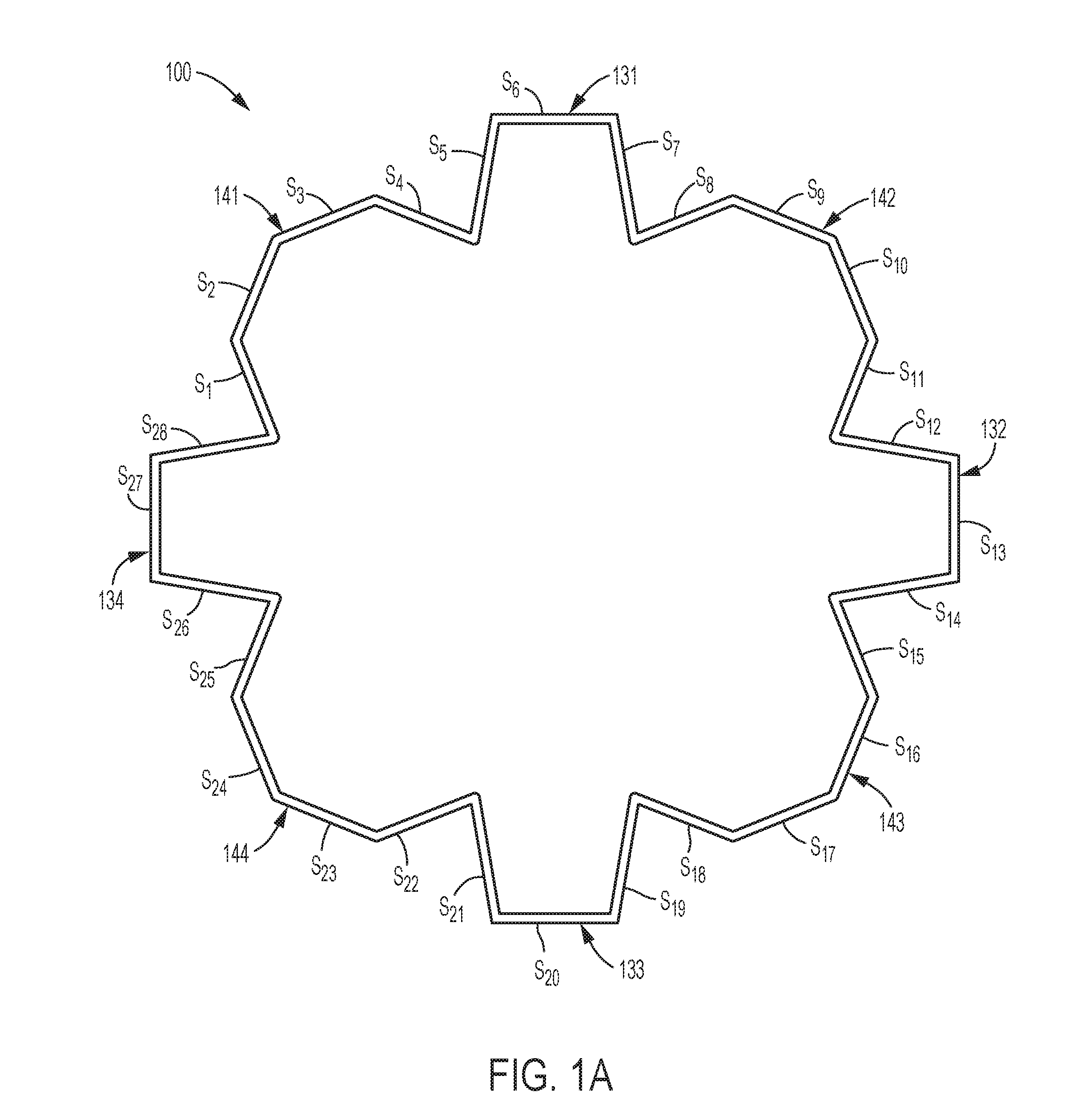
FIG. 1A is a cross-sectional view of a strengthening member having a twenty-eight-cornered cross section including twenty internal angles and eight external angles in accordance with the present teachings;
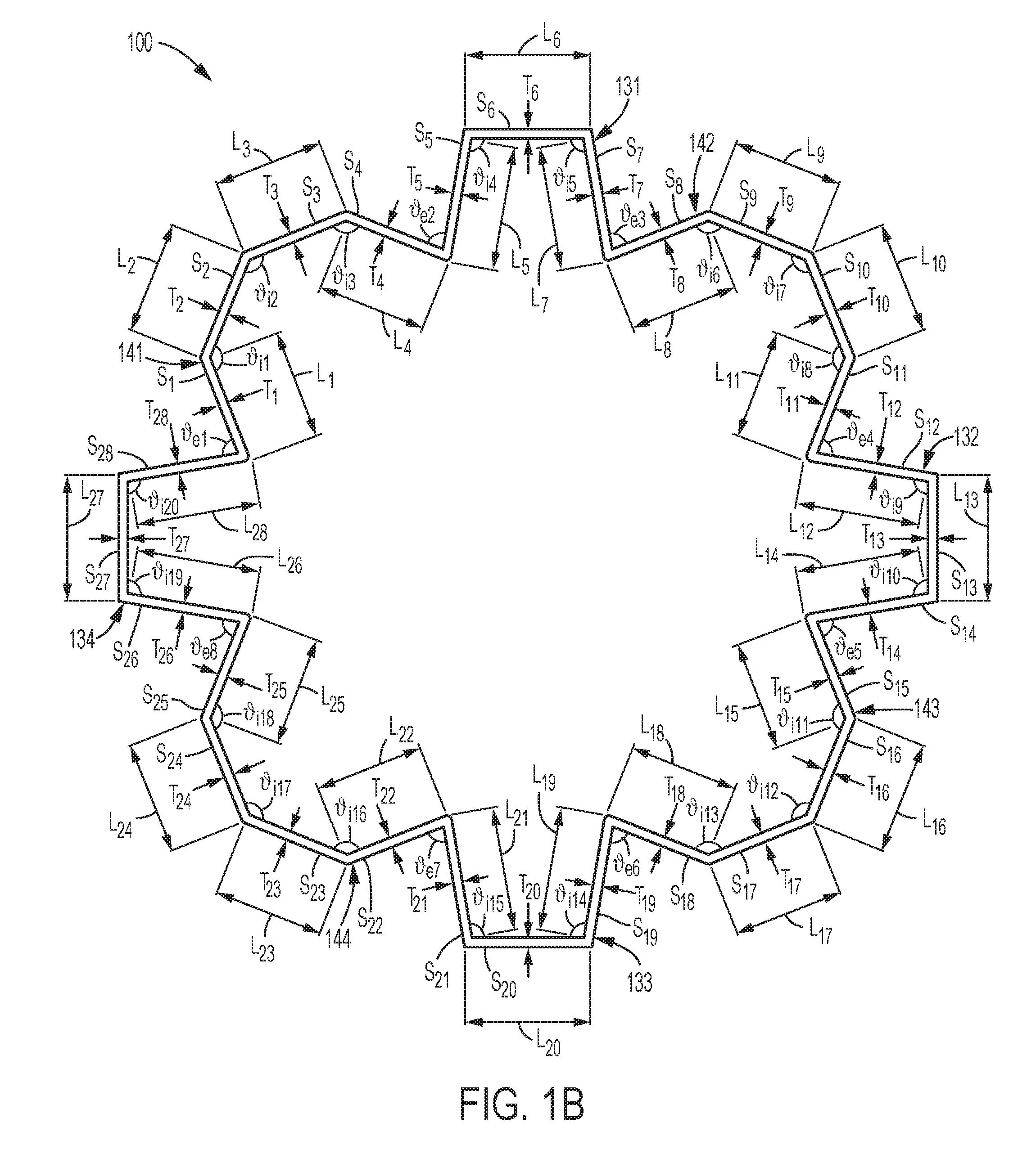
FIG. 1B is another the cross-sectional view of the strengthening member of FIG. 1A, with various lengths, thicknesses, and angles identified;
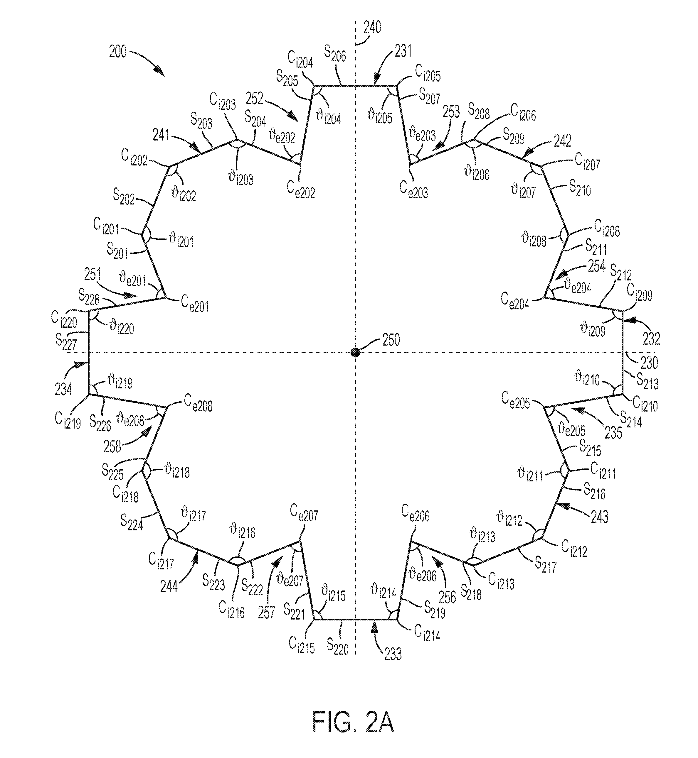
FIGS. 2A-2B are top and perspective views, respectively, of a first exemplary embodiment of a strengthening member having a twenty-eight-cornered cross section with twenty internal angles and eight external angles, as shown in FIG. 1A;
FIGS. 3A-3B are top and perspective views, respectively, of a second exemplary embodiment of a strengthening member having a twenty-eight-cornered cross section with twenty internal angles and eight external angles in accordance with the present teachings;
FIGS. 4A-4B are top and perspective views, respectively, of a third exemplary embodiment of a strengthening member having a twenty-eight-cornered cross section with twenty internal angles and eight external angles in accordance with the present teachings;
FIGS. 5A-5B are top and perspective views, respectively, of a fourth exemplary embodiment of a strengthening member having a twenty-eight-cornered cross section with twenty internal angles and eight external angles in accordance with the present teachings;
FIGS. 6A-6B are top and perspective views, respectively, of a fifth exemplary embodiment of a strengthening member having a twenty-eight-cornered cross section with twenty internal angles and eight external angles in accordance with the present teachings;
FIGS. 7A-7B are top and perspective views, respectively, of a sixth exemplary embodiment of a strengthening member having a twenty-eight-cornered cross section with twenty internal angles and eight external angles in accordance with the present teachings;
FIGS. 8A-8B are top and perspective views, respectively, of a seventh exemplary embodiment of a strengthening member having a twenty-eight-cornered cross section with twenty internal angles and eight external angles in accordance with the present teachings;
FIG. 9 illustrates strengthening members of various cross sections having substantially the same thickness, substantially the longitudinal length, and cross-sectional dimensions along perpendicularly oriented transverse axes with substantially the same lengths;
FIG. 10 illustrates an exemplary quasi-static axial collapse of the strengthening members shown in FIG. 9;
FIG. 11 illustrates an exemplary dynamic crush of the strengthening members shown in FIG. 9;
FIG. 12 is a graph of the dynamic crush force and associated crush distance for the exemplary strengthening members shown in FIG. 9;
FIG. 13 is a graph of the dynamic axial crush energy and associated axial crush distance for the exemplary strengthening members shown in FIG. 9;
FIG. 14 is a perspective view of an exemplary embodiment of a vehicle frame having several components for which a strengthening member having a twenty-eight-cornered cross section with twenty internal angles and eight external angles can be used; and
FIG. 15 is a perspective view of an exemplary embodiment of a vehicle upper body having several components for which a strengthening member having a twenty-eight-cornered cross section with twenty internal angles and eight external angles can be used.
Although the following detailed description makes reference to exemplary illustrative embodiments, many alternatives, modifications, and variations thereof will be apparent to those skilled in the art. Accordingly, it is intended that the claimed subject matter be viewed broadly.
DESCRIPTION OF EXEMPLARY EMBODIMENTS
Reference will now be made in detail to various exemplary embodiments, examples of which are illustrated in the accompanying drawings. The various exemplary embodiments are not intended to limit the disclosure. To the contrary, the disclosure is intended to cover alternatives, modifications, and equivalents of the exemplary embodiments. In the drawings and the description, similar elements are provided with similar reference numerals. It is to be noted that the features explained individually in the description can be mutually combined in any technically expedient manner and disclose additional embodiments of the present disclosure.
This description's terminology is not intended to limit the disclosed subject matter. For example, spatially relative terms--such as "beneath", "below", "lower", "above", "upper", "proximal", "distal", "front", "rear", "left", "right", "horizontal", "vertical", and the like--may be used to describe one element's or feature's relationship to another element or feature as illustrated in the figures. These spatially relative terms are intended to encompass different positions (i.e., locations) and orientations (i.e., rotational placements) of a device in use or operation in addition to the position and orientation shown in the figures. For example, if a device in the figures is turned over, elements described as "below" or "beneath" other elements or features would then be "above" or "over" the other elements or features.
The present teachings contemplate strengthening members with twenty-eight-cornered cross sections. The cross-sectional configuration of these strengthening members provides increased stiffness throughout the sides and corners of the strengthening member when compared to conventional strengthening members. Such conventional strengthening members rely on increasing thickness within the corners to achieve increases in strength, which result in increases in the weight of the strengthen member. The strengthening members of the present disclosure are designed based in part on, for example, a variety of tunable parameters configured to achieve strength increases (i.e., load carrying and energy absorption) over basic polygonal designs (e.g., polygonal strengthening member cross sections having less or the same number of sides), while also allowing design flexibility to meet a range of vehicle applications.
In accordance with the present teachings, the shape of the strengthening members disclosed herein provides the strengthening member with stabilized folding, reduced crush distance, and increased energy absorption in response to an axially applied crash force, when compared to conventional strengthening members. In at least some embodiments, the shape also improves moisture shedding abilities of the strengthening member and permits a more customized fit with other vehicle components.
The strengthening members in accordance with the present teachings can achieve increased energy absorption and a more stable axial collapse when forces such as front and side impact forces are exerted on the strengthening member. Furthermore, the side lengths and configurations, and/or degrees of the internal and external angles, of the strengthening members in accordance with the present teachings can achieve a similar, if not greater, strength increase as thickened corners, while minimizing mass per unit length of the member and maintaining a high manufacturing feasibility because the member can be formed by stamping, bending, press forming, hydro-forming, molding, casting, extrusion, uniform or non-uniform roll forming, machining, forging, 3-D printing, and/or other known suitable manufacturing processes. Thus-formed sections can be joined via welding, brazing, soldering, adhesive bonding, fastening, press fitting or other known joining technologies.
Strengthening members in accordance with the present teachings may be made, for example, of steel alloys, titanium alloys, aluminum alloys, magnesium alloys, nylons, plastics, polymers, composites, fiber-reinforced composites, silicone, semiconductor, papers, hybrid materials (i.e., multiple dissimilar materials), shape-memory materials, foams, gels or any other suitable materials. Those of ordinary skill in the art would understand, for example, that the material used for a strengthening member may be chosen based at least in part on intended application, strength/weight considerations, cost, packaging space, and/or other design factors.
Turning to the drawings, an exemplary embodiment of a cross section of a strengthening member 100 having twenty-eight corners in accordance with the present teachings is illustrated in FIG. 1A. The strengthening member 100 has twenty-eight sides S.sub.1-S.sub.28. The sides S.sub.1-S.sub.28 of the strengthening member may define a cross section of the strengthening member having four lobe portions 141-144 and four protrusion portions 131-134, in accordance with the present teachings. Each lobe portion may be defined by four of the sides, for example, sides S.sub.1-S.sub.4 define a first lobe portion 141, sides S.sub.8-S.sub.11 define a second lobe portion 142, sides S.sub.15-S.sub.18 define a third lobe portion 143, and sides S.sub.22-S.sub.25 define a fourth lobe portion 144 of the cross section of strengthening member 100. Each protrusion portion may be defined by three of the sides, for example, sides S.sub.5-S.sub.7 define a first protrusion portion 131, sides S.sub.12-S.sub.14 define a second protrusion portion 132, sides S.sub.19-S.sub.21 define a third protrusion portion 133, and sides S.sub.26-S.sub.28 define a fourth protrusion portion 134 of the cross section of strengthening member 100.
As labeled in FIG. 1B, the illustrated cross section of the strengthening member 100 comprises twenty-eight sides S.sub.1-S.sub.28 having cross-sectional lengths L.sub.1-L.sub.28 and cross-sectional thicknesses T.sub.1-T.sub.28. Sides S.sub.1-S.sub.28 define twenty internal corners with cross-sectional angles .sub.i1- .sub.i20, and eight external corners with cross-sectional angles .sub.e1- .sub.e8.
The perimeter of the twenty-eight-sided cross section generally forms a polygon comprising a plurality of internal and external corners. As embodied herein and shown in FIGS. 1A-1B, the polygon may be formed of alternating internal and external angles, and in particular, may be formed by alternating three consecutive internal corners/angles and one external corner/angle with two consecutive internal corners/angles and one external corner/angle. This repeating pattern (i.e., an alternating three-in-one-out-two-in-one-out configuration), results in a cross section with up to four bisecting planes of symmetry. Under an axial and symmetric loading condition, strengthening members with symmetrical, polygonal cross sections, including the various embodiments of the present teachings, may have better load carrying capabilities and energy absorbing capabilities than those with asymmetrical, polygonal cross sections with an equivalent number of corners and sides. Furthermore, strengthening members with symmetrical, polygonal cross sections with more than two bisecting planes of symmetry (e.g., three bisecting planes of symmetry, four bisecting planes of symmetry, or five or more bisecting planes of symmetry), including the various embodiments of the present teachings, may have better load carrying capabilities and energy absorbing capabilities than those with symmetrical, polygonal cross sections with two or fewer bisecting planes of symmetry and an equivalent number of corners and sides. For example, the exemplary cross section shown in FIG. 1 has four bisecting planes of symmetry. However, as those of ordinary skill in the art will understand, use of asymmetrical cross sections may offer other benefits that provide advantages that cannot be realized using a symmetrical cross section. The present disclosure contemplates that a twenty-eight-sided, twenty-eight-cornered cross section, in accordance with the present teachings, may be either symmetrical or asymmetrical.
Depending upon the particular application and/or the desired features of the strengthening member, the cross-sectional lengths of the sides and the cross-sectional thicknesses of the sides of the twenty-eight-sided, twenty-eight-cornered strengthening member as well as the internal and external corner angles of the strengthening member can be varied (i.e., can be tuned) to achieve improved strength and other performance features (e.g., stability of folding pattern) of the strengthening member when compared to conventional strengthening members. Varying these features of the twenty-eight-sided, twenty-eight-cornered strengthening member may obviate the need for increased side and/or corner thickness. In accordance with various exemplary embodiments of the present teachings, the cross-sectional lengths L.sub.1-L.sub.28 of sides S.sub.1-S.sub.28, the cross-sectional thicknesses T.sub.1-T.sub.28 of the sides as well as the cross-sectional internal angles .sub.i1- .sub.i20 of the internal corners and external angles .sub.e1- .sub.e8 of the external corners can be varied to a certain degree, as would be understood by one skilled in the art, for example in accordance with available packaging space within a vehicle.
In addition, in a strengthening member in accordance with the present teachings, each internal corner angle .sub.i1- .sub.i20 of a cross section of the strengthening member can range from about 45.degree. to about 175.degree., and each external corner angle .sub.e1- .sub.e8 of a cross section of the strengthening member can range from about 45.degree. to about 175.degree.. In accordance with the present teachings, the internal angles .sub.i1- .sub.i20 of a cross section of the strengthening member may all be substantially the same, and/or, the external angles .sub.e1- .sub.e8 of a cross section of the strengthening member may all be substantially the same. Additionally or alternatively, the present disclosure contemplates embodiments in which at least some of the internal angles .sub.i1- .sub.i20 of a cross section of the strengthening member differ from one another, and/or similarly, at least some of the external angles .sub.e1- .sub.e8 of a cross section of the strengthening member differ from one another.
In various exemplary embodiments according to the present disclosure, the internal angles .sub.i1- .sub.i3, .sub.i6- .sub.i8, .sub.i11- .sub.i13, and .sub.i16- .sub.i18 that at least partially define each lobe portion 141-144 may all be substantially the same, and/or, the internal angles .sub.i4- .sub.5, .sub.i9- .sub.i10, .sub.i14- .sub.i15, and .sub.i19- .sub.i20 that at least partially define each protrusion portion 131-134 may all be substantially the same, and/or the external angles .sub.e1- .sub.e8 may all be substantially the same. In various exemplary embodiments, internal angles .sub.i1- .sub.i3, .sub.i6- .sub.i8, .sub.i11- .sub.i13, and .sub.i16- .sub.i18 that at least partially define each lobe portion 141-144 may each range from about 120.degree. to about 150.degree. or from about 135.degree. to about 139.degree.; internal angles .sub.i4- .sub.5, .sub.i9- .sub.i10, .sub.i14- .sub.i15, and .sub.i19- .sub.i20 that at least partially define each protrusion portion 131-134 may each range from about 90.degree. to about 120.degree. or from about 98.degree. to about 102.degree.; and each external corner angle .sub.e1- .sub.e8 may range from about 60.degree. to about 90.degree. or from about 76.degree. to about 80.degree.. For example, FIG. 1B illustrates an exemplary cross section in which internal angles .sub.i1- .sub.i3, .sub.i6- .sub.i8, .sub.i11- .sub.i13, and .sub.i16- .sub.i18 that at least partially define each lobe portion 141-144 are about 137.degree.; internal angles .sub.i4- .sub.5, .sub.i9- .sub.i10, .sub.i14- .sub.i15, and .sub.i19- .sub.i20 that at least partially define each protrusion portion 131-134 are about 100.degree.; and each external corner angle .sub.e1- .sub.e8 is about 78.degree..
In certain exemplary embodiments of the present disclosure, such as in an automotive application, for example, a cross-sectional length L.sub.1-L.sub.28 of each side S.sub.1-S.sub.28 of a cross section of the strengthening member can range from about 10 mm to about 250 mm. In other exemplary embodiments, such as in an aircraft, spacecraft, watercraft, or building application, for example, a cross-sectional length L.sub.1-L.sub.28 of each side S.sub.1-S.sub.28 of the cross section of the strengthening member may be larger.
FIG. 1B illustrates an exemplary cross section in which cross-sectional lengths L.sub.1-L.sub.4, L.sub.8-L.sub.11, L.sub.15-L.sub.18, and L.sub.22-L.sub.25 of sides S.sub.1-S.sub.4, S.sub.8-S.sub.11, S.sub.15-S.sub.18, and S.sub.22-S.sub.25, respectively, are each a first length, e.g., 20 mm; and cross-sectional lengths L.sub.5-L.sub.7, L.sub.12-L.sub.14, L.sub.19-L.sub.21, and L.sub.26-L.sub.28 of sides S.sub.5-S.sub.7, S.sub.12-S.sub.14, S.sub.19-S.sub.21, and S.sub.26-S.sub.28, respectively, are each a second length, e.g., 20 mm. While the first and second lengths are the same in this example, it is contemplated that the first and second length may be different. It is also contemplated that more than two lengths may be used.
In certain exemplary embodiments of the present disclosure, such as in an automotive application, for example, a thickness T.sub.1-T.sub.28 of the sides of the cross section of the strengthening member can range from about 0.6 mm to about 6.0 mm. In other exemplary embodiments of the strengthening member, such as in an aircraft, spacecraft, watercraft, or building application, for example, a thickness T.sub.1-T.sub.28 of the sides of a cross section of the strengthening member may be larger. In one exemplary embodiment, a cross-sectional thickness T.sub.1-T.sub.28 of each of the sides of the strengthening member may be about 3.3 mm. In another exemplary embodiment, a cross-sectional thickness T.sub.1-T.sub.28 of each of the sides may be about 2.3 mm. In another exemplary embodiment, a cross-sectional thickness T.sub.1-T.sub.28 of each of the sides may be about 2.0 mm. In some exemplary embodiments, the cross-sectional thickness T.sub.1-T.sub.28 of the sides is substantially the same as the thickness of the corners for each side. In some exemplary embodiments the cross-sectional thickness T.sub.1-T.sub.28 of each side wall, (e.g., side walls S.sub.201-S.sub.228, respectively (see FIG. 2A)), can vary with respect to each other side wall. Alternatively or concurrently, the cross-sectional thickness T.sub.1-T.sub.28 can vary along the respective cross-sectional lengths L.sub.1-L.sub.28 of the sides S.sub.1-S.sub.28.
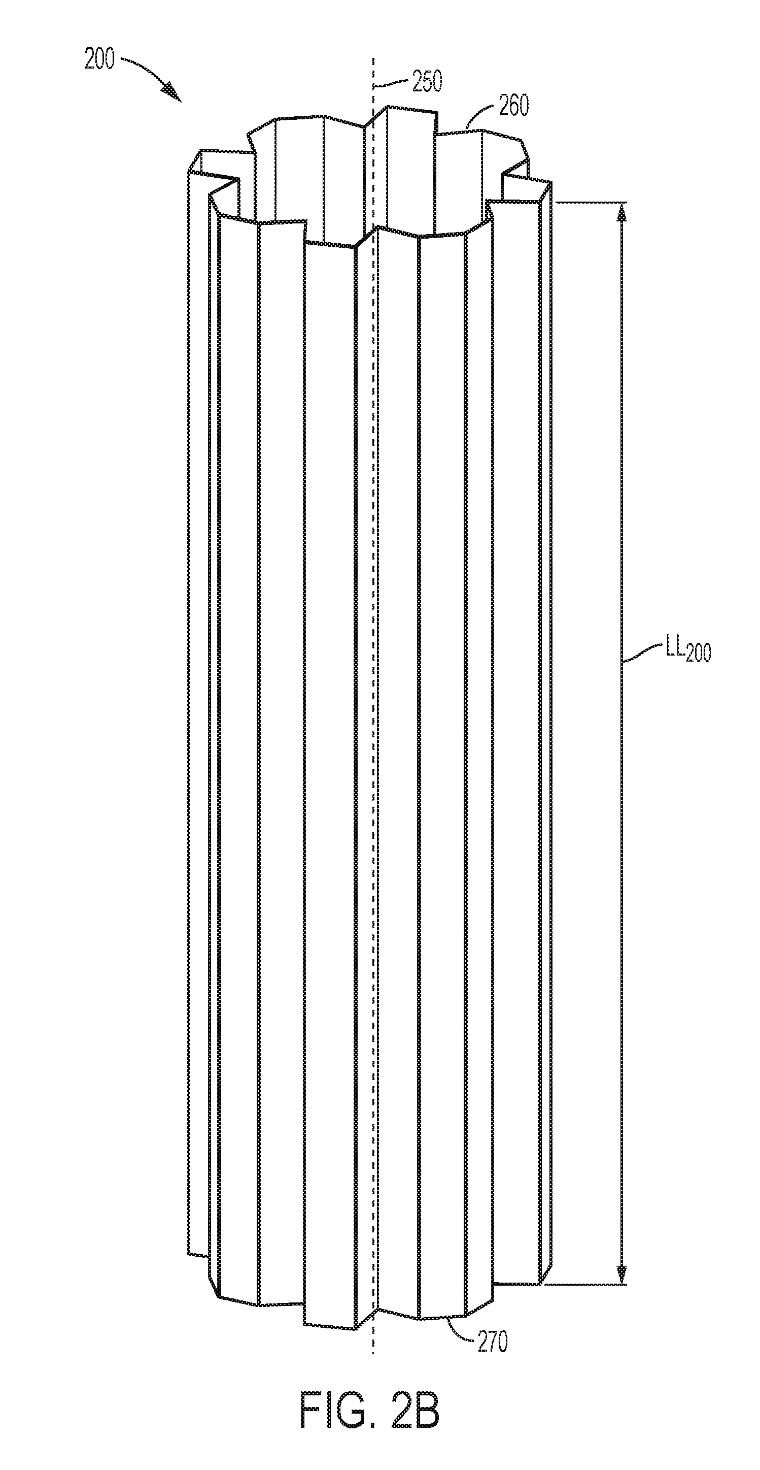
Top and perspective views of a first exemplary embodiment of a strengthening member 200 having a twenty-eight-cornered cross section, with twenty internal angles and eight external angles are illustrated in FIGS. 2A-2B, respectively. Strengthening member 200 has twenty-eight corners C.sub.i201-C.sub.i220 and C.sub.e201-C.sub.e208, and twenty-eight side walls S.sub.201-S.sub.228. Twenty of the corners are internal angle corners C.sub.i201-C.sub.i220 and eight of the corners are external angle corners C.sub.e201-C.sub.e208. The strengthening member 200 includes four lobe portions 241-244 and four protrusion portions 231-234. Each lobe portion is defined by four sides, for example, sides S.sub.201-S.sub.204 define a first lobe portion 241, sides S.sub.208-S.sub.211 define a second lobe portion 244, sides S.sub.215-S.sub.218 define a third lobe portion 243, and sides S.sub.222-S.sub.225 define a fourth lobe portion 244 of strengthening member 200. Each protrusion portion is defined by three sides, for example, sides S.sub.205-S.sub.207 define a first protrusion portion 231, sides S.sub.212-S.sub.214 define a second protrusion portion 232, sides S.sub.219-S.sub.221 define a third protrusion portion 233, and sides S.sub.226-S.sub.228 define a fourth protrusion portion 234 of strengthening member 200. The dimension-to-dimension ratio of the cross section of the strengthening member 200, taken along transverse axes 230, 240 is 1:1.
Also, as shown in FIGS. 2A-2B, strengthening member 200 includes recessed areas 251, 252, 253, 254, 255, 256, 257, and 258. Each recessed area 251-258 extends along the length of the strengthening member 200 from first end 260 to second end 270. A side of an adjacent lobe portion and protrusion portion define each recess along a length of the strengthening member 200.
Strengthening member 200 also has a first transverse axis 230, a second transverse axis 240, and a longitudinal axis 250. Although shown with its longitudinal axis 250 positioned substantially vertically (in FIG. 2B), when strengthening member 200 (as well as all of the other various embodiments in accordance with the present teachings) is installed within a vehicle, the longitudinal axis 250 of the strengthening member may be oriented substantially horizontally.
The strengthening member 200 of FIGS. 2A-2B also has a uniform cross section along a length of the strengthening member 200, from first end 260 to second end 270 of the strengthening member 200. Additionally, the longitudinal length LL.sub.200 of each side S.sub.201-S.sub.228 is approximately the same, as shown in FIG. 2B. As also illustrated, for all cross sections, each of twelve of the internal angles are substantially the same, each of the other eight internal angles are substantially the same, and all eight of the external angles are substantially the same. In various exemplary embodiments, internal angles .sub.i201- .sub.i203, .sub.i206- .sub.i208, .sub.i211- .sub.i213, and .sub.i216- .sub.i218 that at least partially define each lobe portion 141-144 may each range from about 120.degree. to about 150.degree. or from about 135.degree. to about 139.degree.; internal angles .sub.i204, .sub.i205, .sub.i209, .sub.i210, .sub.i214, .sub.i215, .sub.i219, and .sub.i220 that at least partially define each protrusion portion 131-134 may each range from about 90.degree. to about 120.degree. or from about 98.degree. to about 102.degree.; and each external corner angle .sub.e201- .sub.e208 may range from about 76.degree. to about 80.degree.. For example, in the exemplary embodiment of FIGS. 2A-2B, each of twelve of the internal angles .sub.i201- .sub.i203, .sub.i206- .sub.i208, .sub.i211- .sub.i213, and .sub.i216- .sub.i218 that at least partially define each lobe portion 241-244 are about 137.degree.; each of the other eight internal angles .sub.i204, .sub.i205, .sub.i209, .sub.i210, .sub.i214, .sub.i215, .sub.i219, and .sub.i220 that at least partially define each protrusion portion 241-244 are about 100.degree.; and all eight of the external angles .sub.e201- .sub.e208 are 78.degree.. The thicknesses of each sidewall S.sub.201-S.sub.228 are also substantially the same.
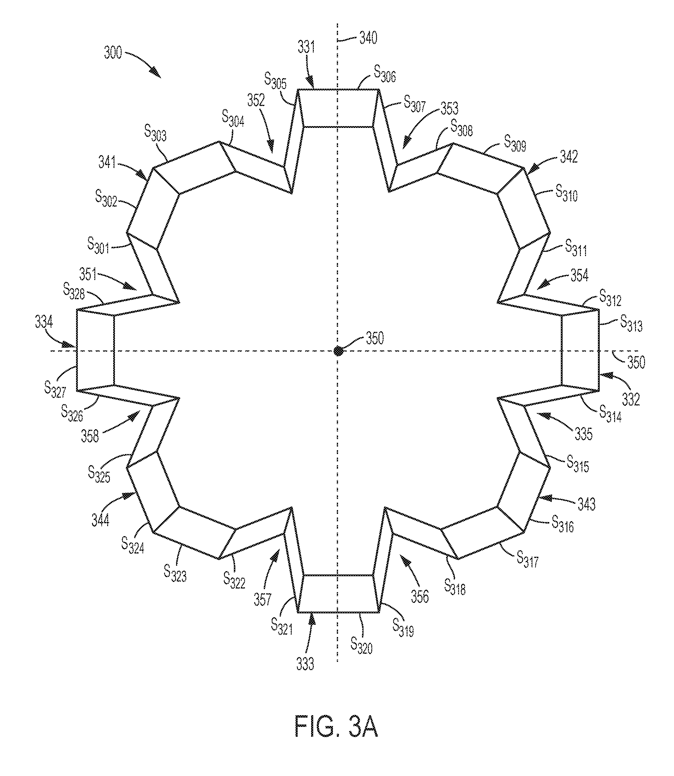
Top and perspective views of an alternative exemplary embodiment of a strengthening member 300 having a twenty-eight-cornered cross section, with twenty internal angles and eight external angles, are illustrated in FIGS. 3A-3B, respectively. The cross section of the strengthening member 300 includes a four lobe portions and four protrusions. Each lobe portion is defined by four sides, for example, sides S.sub.301-S.sub.304 define a first lobe portion 341, sides S.sub.308-S.sub.311 define a second lobe portion 342, sides S.sub.315-S.sub.318 define a third lobe portion 343, and sides S.sub.322-S.sub.325 define a fourth lobe portion 344 of the cross section of strengthening member 300. Each protrusion portion is defined by three sides, for example, sides S.sub.305-S.sub.307 define a first protrusion portion 331, sides S.sub.312-S.sub.314 define a second protrusion portion 332, sides S.sub.319-S.sub.321 define a third protrusion portion 333, and sides S.sub.326-S.sub.328 define a fourth protrusion portion 334 of strengthening member 300. The dimension-to-dimension ratio of the cross section of strengthening member 300, taken along transverse axes 330, 340 is 1:1.
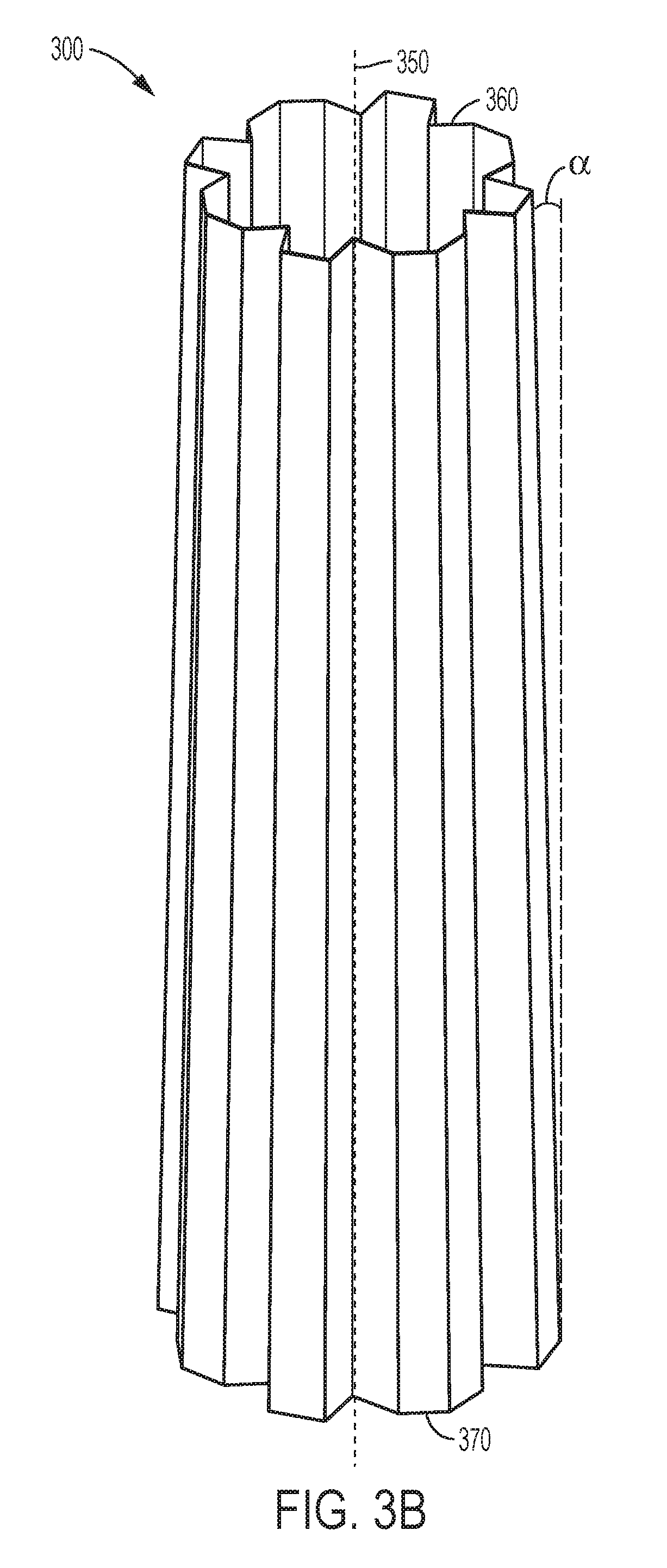
Strengthening member 300 may differ from strengthening member 200 in several aspects. For example, as shown in FIGS. 3A and 3B, one or more of the side walls of the strengthening member may be angled with respect to the longitudinal axis 350 of the strengthening member to provide a taper to at least a portion of the shape of the strengthening member 300. As shown in FIGS. 3A-3B, strengthening member 300 is tapered along its length, from a first end 360 of the strengthening member 300 to a second end 370 of the strengthening member. The strengthening member 300 tapers along its length at an angle .alpha., which may range from about 1.degree. to about 65.degree.. The degree of taper of each side wall may be substantially the same, or different side walls may exhibit differing degrees of taper. Tapering may be required due to component packaging constraints and/or to effectively couple, attach or otherwise bond other components to a strengthening member.
In the exemplary embodiment of FIGS. 3A-3B, like the embodiment of FIGS. 2A-2B, each of twelve of the internal angles that at least partially define each lobe portion 341-344 are about 137.degree., each of the other eight internal angles that at least partially define each protrusion portion 331-334 are about 100.degree., and each of the eight external angles are about 78.degree.. Also, as shown in FIGS. 3A-3B, strengthening member 300 includes recessed areas 351, 352, 353, 354, 355, 356, 357, and 358. Each recessed area 351-358 extends along the length of the strengthening member 300 from first end 360 to second end 370. A side of an adjacent lobe portion and protrusion portion define each recess along a length of the strengthening member 300.
In the disclosed exemplary embodiment of FIGS. 3A-3B, the cross-sectional lengths of each of the twenty-eight sides are each approximately the same as the cross-sectional lengths of other sides when taken at any cross section along the longitudinal length of the strengthening member 300. However, the cross-sectional length of each side gradually/incrementally increases along the longitudinal axis 350 of the strengthening member 300 from first end 360 to second end 370 to provide the tapered shape. As noted above, the embodiment of FIGS. 3A-3B is exemplary, and therefore all of the contemplated embodiments with variations to the cross-sectional lengths and thicknesses of the sides, and to the angles of the internal and external corner angles of the twenty-eight-cornered cross sections, with twenty internal angles and eight external angles, of the strengthening members in accordance with the present teachings are not shown in the figures, but based on the teachings herein, will be apparent to those of skill in the art.
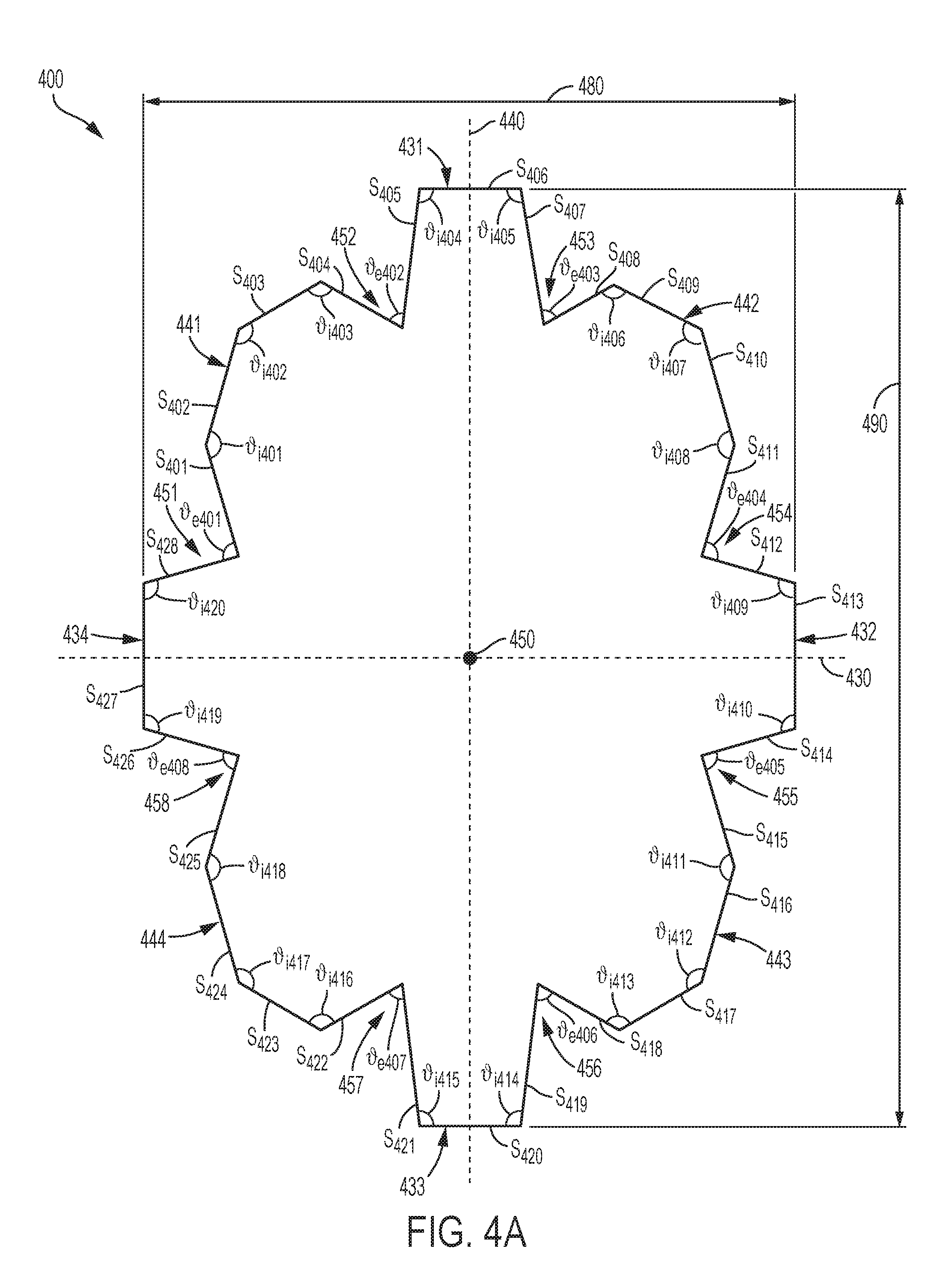
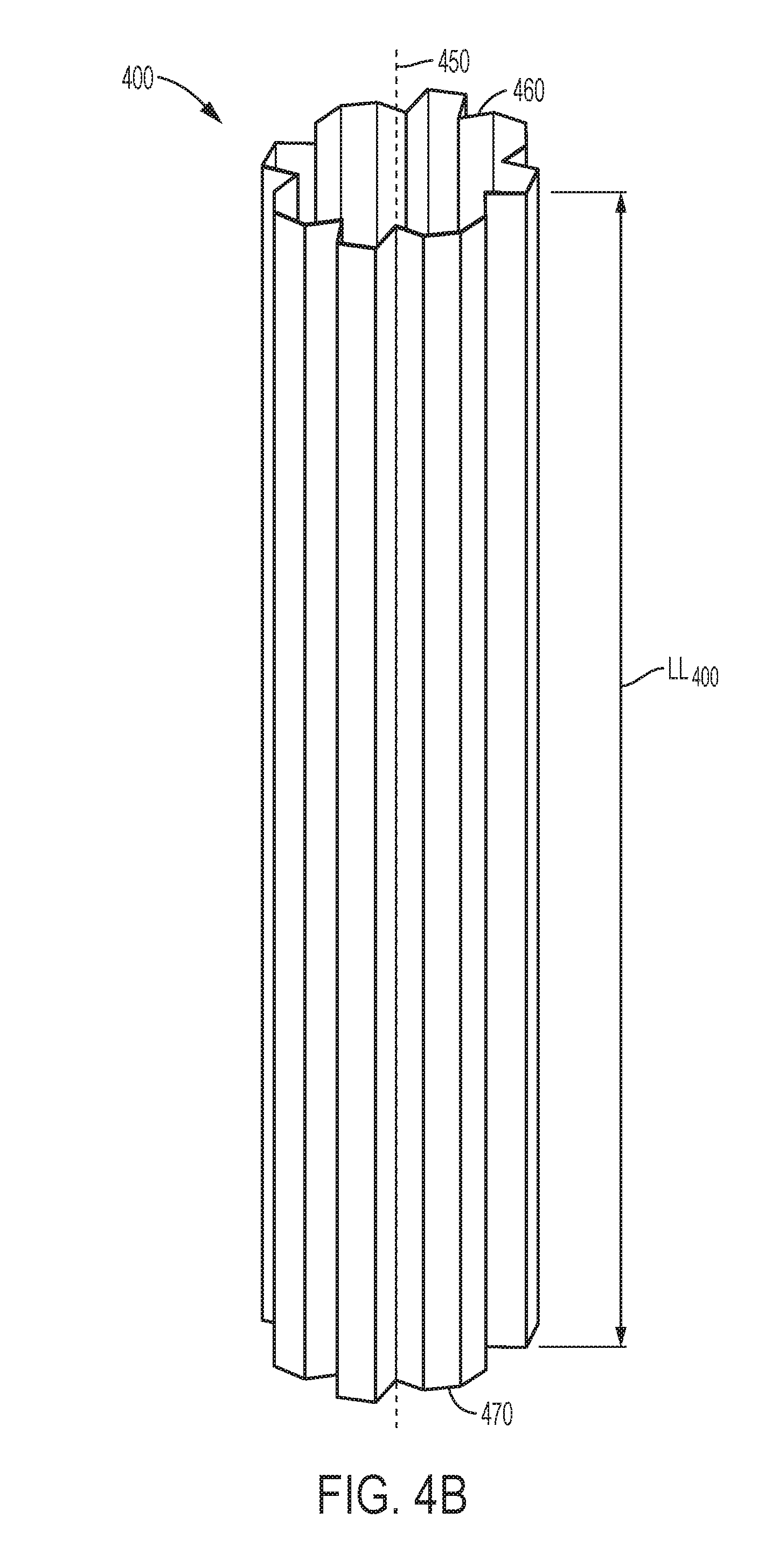
Top and perspective views of an alternative exemplary embodiment of a strengthening member 400 having the twenty-eight-cornered cross section, with twenty internal angles and eight external angles, are illustrated in FIGS. 4A-4B, respectively. The cross section of strengthening member 400 includes four lobe portions 441-444 and four protrusion portions 431-434. Each lobe portion is defined by four sides, for example, sides S.sub.401-S.sub.404 define a first lobe portion 441, sides S.sub.408-S.sub.411 define a second lobe portion 442, sides S.sub.415-S.sub.418 define a third lobe portion 443, and sides S.sub.422-S.sub.425 define a fourth lobe portion 444 of the cross section of strengthening member 400. Each protrusion portion is defined by three sides, for example, sides S.sub.405-S.sub.407 define a first protrusion portion 431, sides S.sub.412-S.sub.414 define a second protrusion portion 432, sides S.sub.419-S.sub.421 define a third protrusion portion 433, and sides S.sub.426-S.sub.428 define a fourth protrusion portion 434 of strengthening member 400.
Similar to the strengthening member 200, strengthening member 400 has a uniform cross section along a length LL.sub.400 of the strengthening member 400, from a first end 460 to a second end 470 of the strengthening member 400. However, as shown in FIGS. 4A-4B, strengthening member 400 differs from strengthening members 200 and 300 in that the dimension-to-dimension ratio of the cross section of the strengthening member, taken along transverse axes 430, 440 is not 1:1; rather, the aspect ratio is about 7:10. FIGS. 4A-4B illustrate a strengthening member cross section that has a first length 480 along a first (minor) transverse axis 430 and a second length 490 along a second (major) transverse axis 440, where the second transverse axis 440 is perpendicular to the first transverse axis 430. The aspect ratio of a strengthening member may be defined as [length along minor axis]:[length along major axis] or [first length 480]:[second length 490].
In the exemplary embodiment of FIGS. 4A-4B, the internal corner angles internal angles .sub.i401- .sub.i403, .sub.i406- .sub.i408, .sub.i411- .sub.i413, and .sub.i416- .sub.i418 are not all the same and internal corner angles internal angles .sub.i404, .sub.i405, .sub.i409, .sub.i410, .sub.i414, .sub.i415, .sub.i419, and .sub.i420 are not all the same. In various exemplary embodiments, internal angles .sub.i401, .sub.i408, .sub.i411, and .sub.i418 may each have a first measurement that ranges from about 120.degree. to about 170.degree. or from about 148.degree. to about 152.degree.; internal angles .sub.i402, .sub.i407, .sub.i412, and .sub.i417 may each have a second measurement that ranges from about 120.degree. to about 170.degree. or from about 133.degree. to about 137.degree.; internal angles .sub.i403, .sub.i406, .sub.i413, and .sub.i416 may each have a third measurement that ranges from about 90.degree. to about 140.degree. or from about 120.degree. to about 124.degree.; internal angles .sub.i404, .sub.i405, .sub.i414, and .sub.i415 may each have a fourth measurement that ranges from about 90.degree. to about 140.degree. or from about 96.degree. to about 100.degree.; and internal angles .sub.i409, .sub.i410, .sub.i419, and .sub.i420 may each have a fifth measurement that ranges from about 90.degree. to about 140.degree. or from about 113.degree. to about 117.degree.. For example, as shown in FIG. 4A, internal angles .sub.i401, .sub.i408, .sub.i411, and .sub.i418 have a first measurement, e.g., of about 150.degree.; internal angles .sub.i402, .sub.i407, .sub.i412, and .sub.i417 have a second measurement, e.g., of about 135.degree.; internal angles .sub.i403, .sub.i406, .sub.i413, and .sub.i416 have a third measurement, e.g., of about 122.degree.; internal angles .sub.i404, .sub.i405, .sub.i414, and .sub.i415 have a fourth measurement, e.g., of about 98.degree.; and internal angles .sub.i409, .sub.i410, .sub.i419, and .sub.i420 have a fifth measurement, e.g., of about 115.degree..
Additionally, the external angles of the exemplary embodiment of FIGS. 4A-4B are not all same. In various exemplary embodiments, external angles .sub.e401, .sub.e404, .sub.e405, and .sub.e408 may each have a sixth measurement that ranges from about 70.degree. to about 120.degree. or from about 87.degree. to about 91.degree.; and external angles .sub.e402, .sub.e403, .sub.e406, and .sub.e407 may each have a seventh measurement that ranges from about 50.degree. to about 90.degree. or from about 67.degree. to about 71.degree.. For example, as shown in FIG. 4A, the external angles .sub.e401, .sub.e404, .sub.e405, and .sub.e408, have a sixth measurement, e.g., of about 89.degree.; and external angles .sub.e402, .sub.e403, .sub.e406, and .sub.e407 have a seventh measurement, e.g., of about 69.degree..
As also shown in FIGS. 4A-4B, the sides of the strengthening member 400 have differing cross-sectional lengths. In addition, the strengthening member 400 of the exemplary embodiment shown in FIGS. 4A-4B includes recessed areas 451-458 spaced around the perimeter of the strengthening member and extending along the length of the strengthening member 400, each recessed area 451-458 extending from first end 460 to second end 470 of strengthening member 400. Sides of adjacent lobe and protrusion portions define each recess along a length of the strengthening member 400. As noted above, the embodiment of FIGS. 4A-4B is exemplary, and therefore all of the contemplated embodiments with variations to the cross-sectional lengths of the sides, thicknesses of the sides, the angles of the internal and external corner angles, and the aspect ratio of the twenty-eight-cornered cross sections, with twenty internal angles and eight external angles, of the strengthening members in accordance with the present teachings are not shown in the figures.
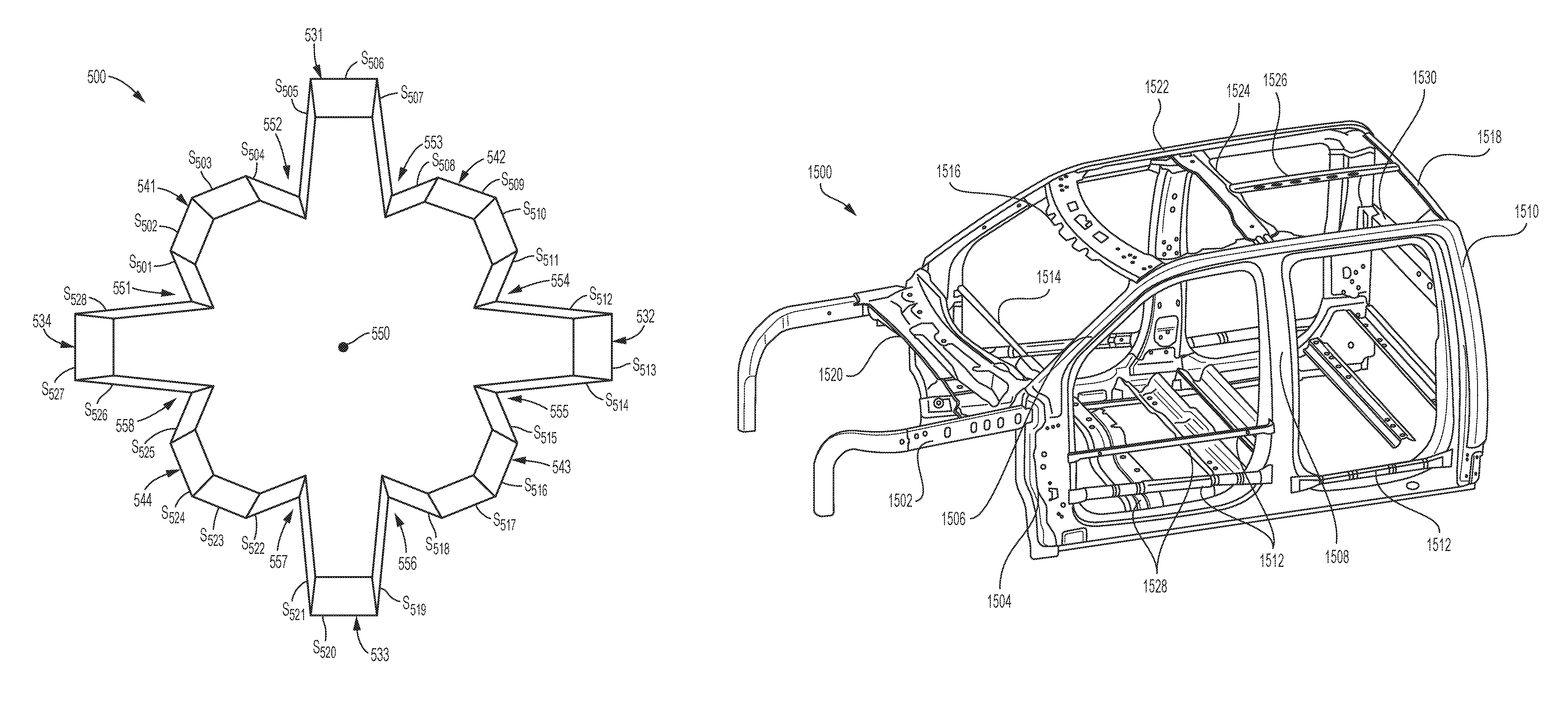
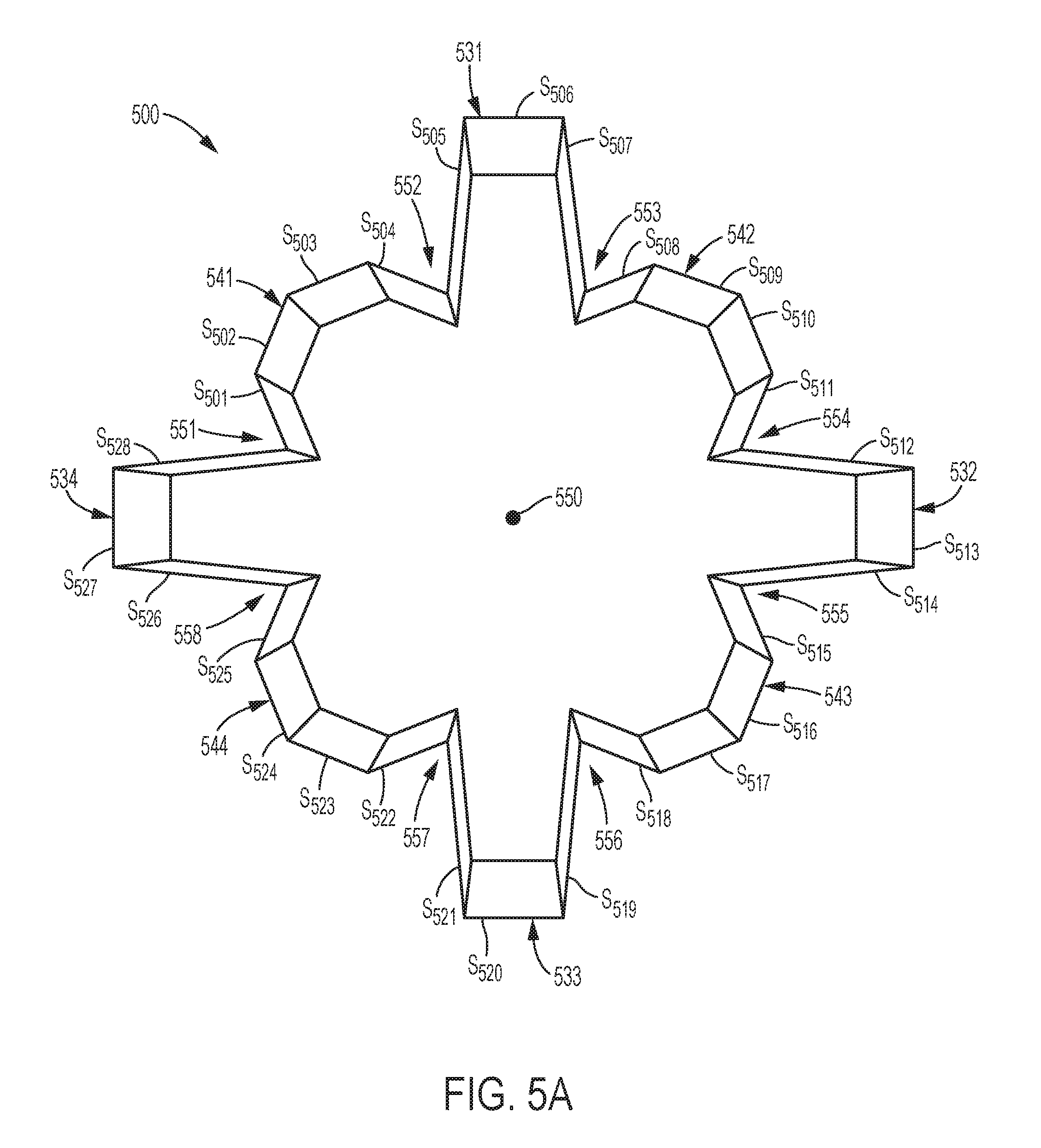
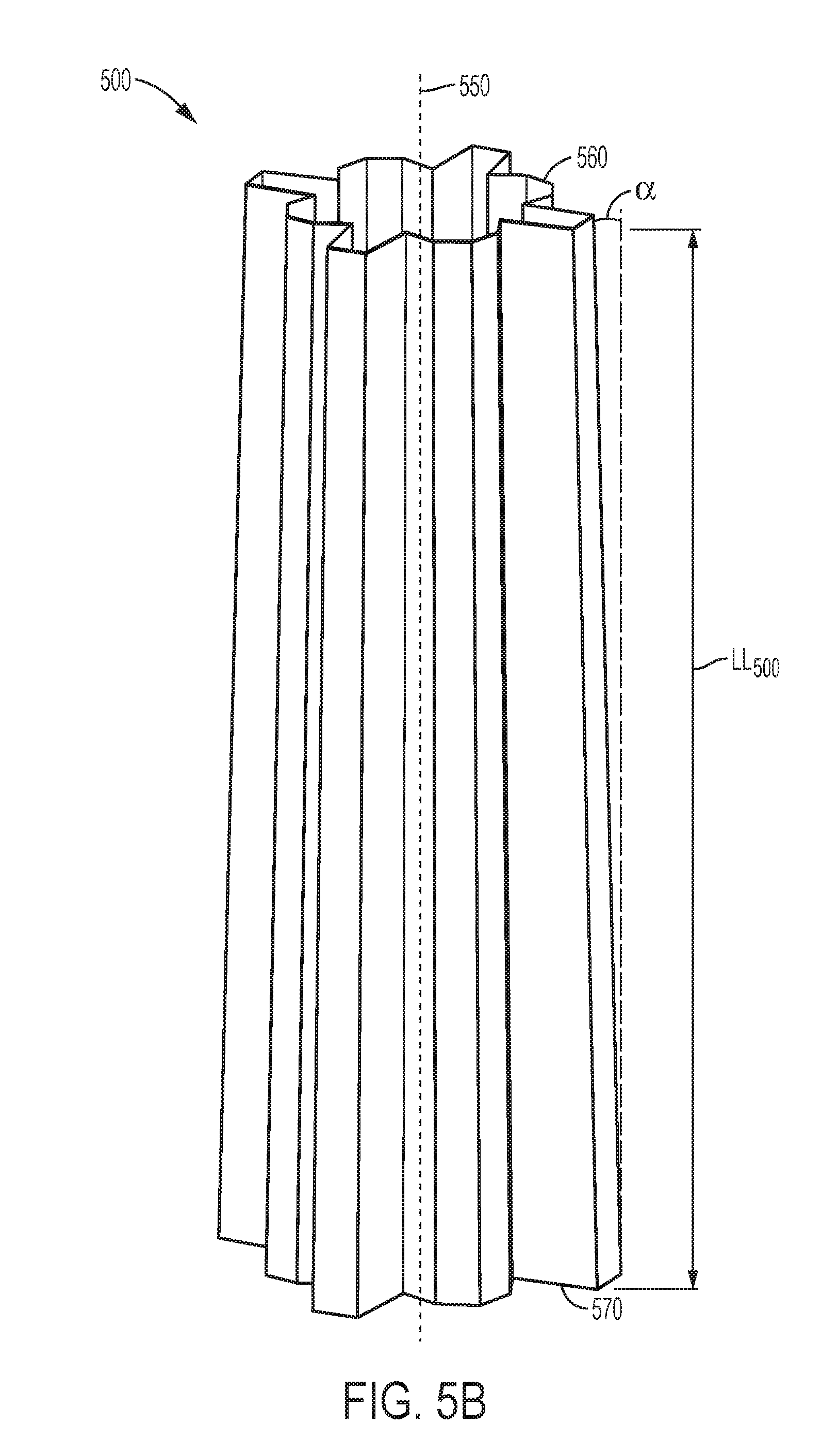
Top and perspective views of an alternative exemplary embodiment of a strengthening member 500 having the twenty-eight-cornered cross section, with twenty internal angles and eight external angles, are illustrated in FIGS. 5A-5B, respectively. The cross section of strengthening member 500 includes four lobe portions and four protrusion portions. Each lobe portion is defined by four sides, for example, sides S.sub.501-S.sub.504 define a first lobe portion 541, sides S.sub.505-S.sub.511 define a second lobe portion 542, sides S.sub.515-S.sub.515 define a third lobe portion 543, and sides S.sub.522-S.sub.525 define a fourth lobe portion 544 of the cross section of strengthening member 500. Each protrusion portion is defined by three sides, for example, sides S.sub.505-S.sub.507 define a first protrusion portion 531, sides S.sub.512-S.sub.514 define a second protrusion portion 532, sides S.sub.519-S.sub.521 define a third protrusion portion 533, and sides S.sub.526-S.sub.528 define a fourth protrusion portion 534 of strengthening member 500. In addition, strengthening member 500 of the exemplary embodiment shown in FIGS. 5A-5B includes recessed areas 551-558 spaced around the perimeter of the strengthening member and extending along the length LL.sub.500 of the strengthening member 500, each recessed area 551-558 extending from first end 560 to second end 570 of strengthening member 500.
Similar to the strengthening member 300, strengthening member 500 tapers along its longitudinal axis 550 from a first end 560 of the strengthening member to a second end 570 of the strengthening member 500. Strengthening member 500 tapers along its length at an angle .alpha., which can range from about 1.degree. to about 65.degree.. In various exemplary embodiments, internal angles that at least partially define each lobe portion 541-544 may each range from about 120.degree. to about 160.degree. or from about 138.degree. to about 142.degree.; internal angles that at least partially define each protrusion portion 531-534 may each range from about 70.degree. to about 120.degree. or from about 93.degree. to about 97.degree.; and each external corner angle may range from about 50.degree. to about 100.degree. or from about 71.degree. to about 75.degree.. For example, in the exemplary embodiment of FIGS. 5A-5B, each of twelve of the internal angles that at least partially define each lobe portion 541-544 are about 140.degree., each of the other eight internal angles that at least partially define each protrusion portion 531-534 are about 95.degree., and each of the eight external angles are about 73.degree..
As illustrated in FIG. 5A, the cross-sectional length of each side wall S.sub.505, S.sub.507, S.sub.512, S.sub.514, S.sub.519, S.sub.521, S.sub.526, and S.sub.528 is long relative to the cross-sectional length of each of the remaining side walls. This difference in the lengths of the sides, in combination with the angle sizes specified above, provides protrusion portions 531-534 that extend farther outward in a radial direction from the longitudinal axis 550 than the radial extent of the lobe portions 541-544. This type of parameter tuning, i.e., changing the cross-sectional lengths of the sides to increase the extension of the protrusion portions 531-534 relative to the extension of the lobe portions 541-544 can increase the internal volume of the protrusion portions 531-534, thereby providing internal cavities that are relatively larger, deeper, and/or cavities with greater than 180 degree protection in the form of longitudinal side walls for other vehicle components that may require extra protection and separation. Such vehicle components may include, for example, brake line(s), pipe(s), electric wire(s), cable(s), and/or seatbelt(s). Disposition of the vehicle components within the completely enclosed side walls of the strengthening member function as a shelter to protect the other vehicle components from being damaged, for example, during vehicle impact events. Additionally, increasing the extension of one or more protrusion portions can allow the strengthening member to be connected or otherwise coupled to adjacent component(s), for example, by bridging the distance between components without enlarging the entire cross section of the strengthening member. Also, increasing the extension of one or more protrusion portions may be advantageous when the design space has relatively more room in directions along transverse axes that are aligned with the protrusion portions, but is restricted in the other radial directions (e.g., the directions in alignment with the transverse axes in alignment with the lobe portions).
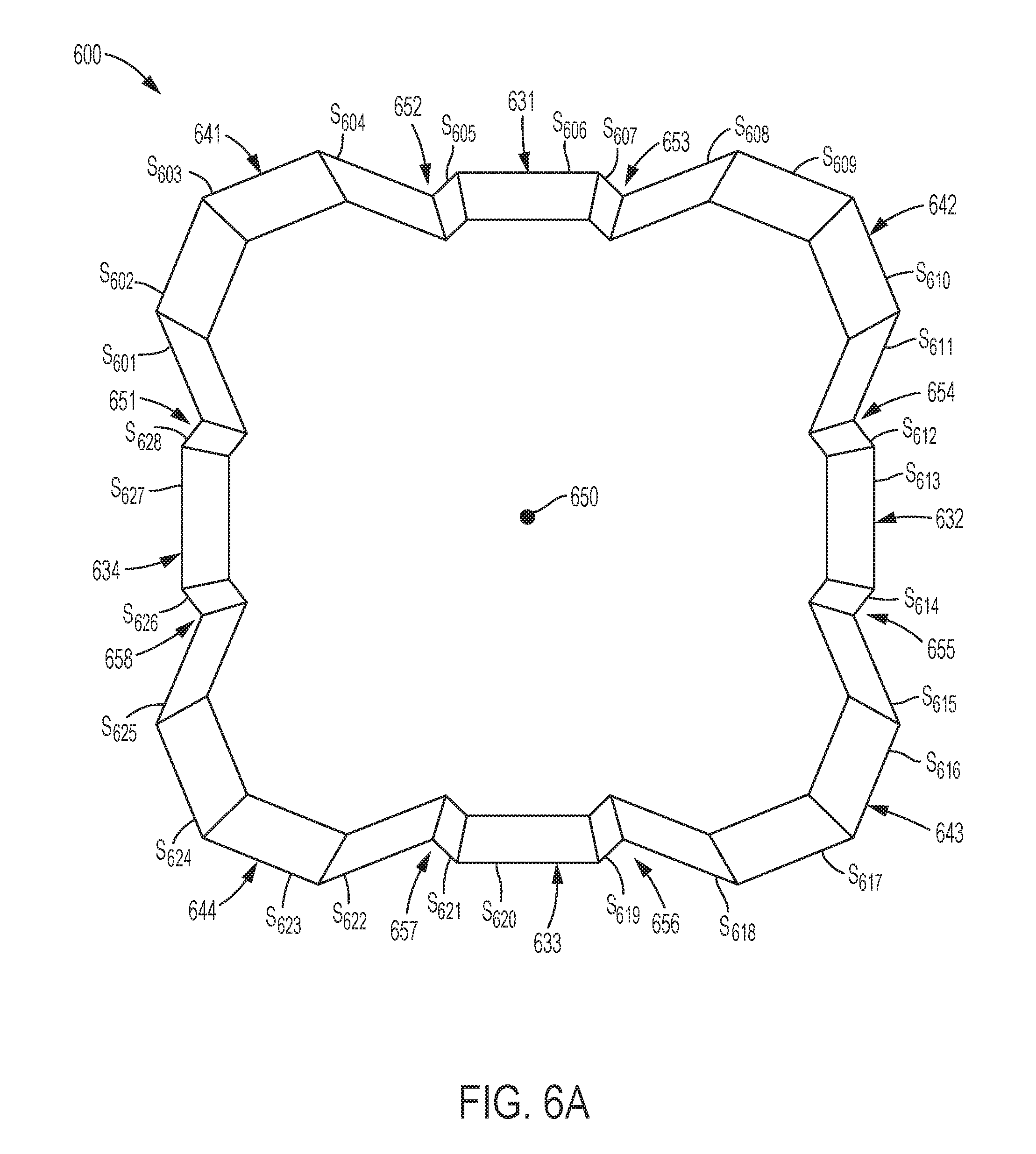
Top and perspective views of an alternative exemplary embodiment of a strengthening member 600 having the twenty-eight-cornered cross section, with twenty internal angles and eight external angles, are illustrated in FIGS. 6A-6B, respectively. The cross section of strengthening member 600 includes four lobe portions and four protrusion portions. Each lobe portion is defined by four sides, for example, sides S.sub.601-S.sub.604 define a first lobe portion 641, sides S.sub.608-S.sub.611 define a second lobe portion 642, sides S.sub.615-S.sub.618 define a third lobe portion 643, and sides S.sub.622-S.sub.625 define a fourth lobe portion 644 of the cross section of strengthening member 600. Each protrusion portion is defined by three sides, for example, sides S.sub.605-S.sub.607 define a first protrusion portion 631, sides S.sub.612-S.sub.614 define a second protrusion portion 632, sides S.sub.619-S.sub.621 define a third protrusion portion 633, and sides S.sub.626-S.sub.628 define a fourth protrusion portion 634 of strengthening member 600. In addition, the strengthening member 600 of the exemplary embodiment shown in FIGS. 6A-6B includes recessed areas 651-658 spaced around the perimeter of the strengthening member and extending along the length of the strengthening member 600, each recessed area 651-658 extending from first end 660 to second end 670 of strengthening member 600.
Similar to the strengthening members 300 and 500, strengthening member 600 tapers along its longitudinal axis 650 from a first end 660 of the strengthening member to a second end 670 of the strengthening member 600. The strengthening member 600 tapers along its length at an angle .alpha., which can range from about 1.degree. to about 65.degree.. In various exemplary embodiments, internal angles that at least partially define each lobe portion 641-644 may each range from about 90.degree. to about 130.degree. or from about 134.degree. to about 138.degree.; internal angles that at least partially define each protrusion portion 631-634 may each range from about 110.degree. to about 150.degree. or from about 133.degree. to about 137.degree.; and each external corner angle may range from about 50.degree. to about 100.degree. or from about 110.degree. to about 114.degree.. For example, in the exemplary embodiment of FIGS. 6A-6B, each of twelve of the internal angles that at least partially define each lobe portion 641-644 are about 136.degree., each of the other eight internal angles that at least partially define each protrusion portion 631-634 are about 135.degree., and each of the eight external angles are about 112.degree..
As illustrated in FIG. 6A, the cross-sectional length of each side wall S.sub.605, S.sub.607, S.sub.612, S.sub.614, S.sub.619, S.sub.621, S.sub.626, and S.sub.628 is short relative to the cross-sectional length of each of the remaining side walls. This difference in the lengths of the sides, in combination with the angle sizes specified above, provides lobe portions 641-644 that extend farther outward in a radial direction from the longitudinal axis 550 than the radial extent of the protrusion portions 631-634. Accordingly, the internal cavity defined by the protrusion portions 631-634 is relatively smaller/shallow. This type of parameter tuning, i.e., changing the cross-sectional lengths of certain sides to decrease the extension of the protrusion portions 631-634 relative to the extension of the lobe portions 641-644 can decrease the internal volume of the protrusion portions 631-634, thereby providing a cross section that may be more compatible for fitting with existing vehicle components. Also, decreasing the extension of one or more protrusion portions may be advantageous when the design space has relatively less room in directions along transverse axes that are aligned with the protrusion portions, but has relatively more room in the other radial directions (e.g., the directions in alignment with the transverse axes in alignment with the lobe portions).
Top and perspective views of an alternative exemplary embodiment of a strengthening member 700 having a twenty-eight-cornered cross section, with twenty internal angles and eight external angles, are illustrated in FIGS. 7A-7B, respectively. Strengthening member 700 has twenty-eight corners C.sub.i701-C.sub.i720 and C.sub.e701-C.sub.e708, and twenty-eight side walls S.sub.701-S.sub.728. Twenty of the corners are internal angle corners C.sub.i701-C.sub.i720 and eight of the corners are external angle corners C.sub.e701-C.sub.e708. Strengthening member 700 also has a first transverse axis 730, a second transverse axis 740, and a longitudinal axis 750. The dimension-to-dimension ratio of the cross section of the strengthening member 700, taken along transverse axes 730, 740 is not 1:1; rather, the aspect ratio is about 7:10.
In the exemplary embodiment of FIGS. 7A-7B, the internal corner angles .sub.i701- .sub.i703, .sub.i706- .sub.i708, .sub.i711- .sub.i713, and .sub.i716- .sub.i718 are not all the same and internal corner angles .sub.i704, .sub.i705, .sub.i709, .sub.i710, .sub.i714, .sub.i715, .sub.i719, and .sub.i720 are not all the same. In various exemplary embodiments, internal angles .sub.i701, .sub.i708, .sub.i711, and .sub.i718 may each have a first measurement that ranges from about 145.degree. to about 175.degree. or from about 163.degree. to about 167.degree.; internal angles .sub.i702, .sub.i707, .sub.i712, and .sub.i717 may each have a second measurement that ranges from about 120.degree. to about 160.degree. or from about 138.degree. to about 142.degree.; internal angles .sub.i703, .sub.i706, .sub.i713, and .sub.i716 may each have a third measurement that ranges from about 135.degree. to about 175.degree. or from about 152.degree. to about 156.degree.; internal angles .sub.i704, .sub.i705, .sub.i714, and .sub.i715 may each have a fourth measurement that ranges from about 95.degree. to about 120.degree. or from about 98.degree. to about 102.degree.; and internal angles .sub.i709, .sub.i710, .sub.i719, and .sub.i720 may each have a fifth measurement that ranges from about 95.degree. to about 120.degree. or from about 105.degree. to about 107.degree.. For example, as shown in FIG. 7A, internal angles .sub.i701, .sub.i708, .sub.i711, and .sub.i718 have a first measurement, e.g., of about 165.degree.; internal angles .sub.i702, .sub.i707, .sub.i712, and .sub.i717 have a second measurement, e.g., of about 140.degree.; internal angles .sub.i703, .sub.i706, .sub.i713, and .sub.i716 have a third measurement, e.g., of about 154.degree.; internal angles .sub.i704, .sub.i705, .sub.i714, and .sub.i715 have a fourth measurement, e.g., of about 100.degree.; and internal angles .sub.i709, .sub.i710, .sub.i719, and .sub.i720 have a fifth measurement, e.g., of about 107.degree..
Additionally, in the exemplary embodiment of FIGS. 7A-7B, the external angles are not all same. In various exemplary embodiments, external angles .sub.e701, .sub.e704, .sub.e705, and .sub.e708 may each have a fifth measurement that ranges from about 95.degree. to about 140.degree.; and external angles .sub.e702, .sub.e703, .sub.e706, and .sub.e707 may each have a sixth measurement that ranges from about 95.degree. to about 130.degree. (different from the fifth measurement). For example, as shown in FIG. 7A, the external angles .sub.e701, .sub.e704, .sub.e705, and .sub.e708, have a sixth measurement, e.g., of about 116.degree.; and external angles .sub.e702, .sub.e703, .sub.e706, and .sub.e707 have a seventh measurement, e.g., of about 108.degree..
Although shown with its longitudinal axis 750 positioned substantially vertically in FIG. 7B, when strengthening member 700 (as well as all of the other various embodiments in accordance with the present teachings) is installed within a vehicle, the longitudinal axis 750 of the strengthening member may be oriented substantially horizontally. In this position, first transverse axis 730 may be oriented substantially horizontally and second transverse axis 740 may be oriented substantially vertically, as shown in FIG. 7A. When installed in such a position, the shape of strengthening member 700 facilitates the reduction or prevention of moisture collecting or pooling along portions of the walls of strengthening member 700. For example, certain conventional strengthening members whose walls form adjacent external angles of 90 degrees or form rectangular, square, or U-shaped recesses or depressions may collect moisture or permit moisture to pool in the recesses, increasing the possibility of weakening of the strengthening member via rusting, stripping, cracking, etc. (i.e., any form of oxidation or other chemical or physical distortion which the material of manufacture of the strengthening member may be more susceptible to due to the presence of moisture).
In contrast, strengthening member 700 does not include a recessed portion in which liquids or moisture can remain for a long period of time. In particular, each of the internal angles .sub.i701- .sub.i720 and external angles .sub.e701- .sub.e708 have been selected such that the walls of strengthening member 700 are angled relative to one another to promote shedding of any moisture or fluid that falls within any recessed portion of the strengthening member. For example, as shown in FIGS. 7A and 7B, strengthening member 700 includes internal angles .sub.i701- .sub.i720 that are obtuse, and external angles .sub.e701- .sub.e708 that are obtuse. As a result, side walls S.sub.701-S.sub.728 are sloped/angled such that fluid impinging or collecting on side walls S.sub.701-S.sub.728 will run off the exterior of the strengthening member 700 due in part or in whole to gravitational forces.
Top and perspective views of an alternative exemplary embodiment of a strengthening member 800 having a twenty-eight-cornered cross section, with twenty internal angles and eight external angles, are illustrated in FIGS. 8A-8B, respectively. Strengthening member 800 has twenty-eight corners and twenty-eight side walls S.sub.801-S.sub.828. Twenty of the corners are internal angle corners and eight of the corners are external angle corners. Strengthening member 800 also has a first transverse axis 830, a second transverse axis 840, and a longitudinal axis 850. The dimension-to-dimension ratio of the cross section of the strengthening member 800, taken along transverse axes 830, 840 is 1:1.
In various exemplary embodiments, internal angles that at least partially define each lobe portion 841-844 may each range from about 130.degree. to about 175.degree. or from about 151.degree. to about 155.degree.; internal angles that at least partially define each protrusion portion 831-834 may each range from about 95.degree. to about 130.degree. or from about 96.degree. to about 100.degree.; and each external corner angle may range from about 95.degree. to about 130.degree. or from about 94.degree. to about 98.degree.. For example, in the exemplary embodiment of FIGS. 8A-8B, each of twelve of the internal angles that at least partially define each lobe portion 841-844 are about 153.degree., each of the other eight internal angles that at least partially define each protrusion portion 831-834 are about 98.degree., and each of the eight external angles are about 96.degree..
Although shown with its longitudinal axis 850 positioned substantially vertically in FIG. 8B, when strengthening member 800 (as well as all of the other various embodiments in accordance with the present teachings) is installed within a vehicle, longitudinal axis 850 of strengthening member may be oriented substantially horizontally. In this position, first transverse axis 830 may be oriented substantially horizontally and second transverse axis 840 may be oriented substantially vertically, as shown in FIG. 8A. When installed in such a position, the shape of strengthening member 800 facilitates the reduction or prevention of moisture collecting or pooling along portions of the walls of strengthening member 800. For example, certain conventional strengthening members whose walls form adjacent external angles of 90 degrees or form rectangular, square, or U-shaped recesses or depressions may collect moisture or permit moisture to pool in the recesses, increasing the possibility of weakening of the strengthening member via rusting, stripping, cracking, etc. (i.e., any form of oxidation or other chemical or physical distortion which the material of manufacture of the strengthening member may be more susceptible to due to the presence of moisture).
In contrast, strengthening member 800 does not include a recessed portion in which liquids or moisture can remain for a long period of time. In particular, each of the internal angles .sub.i801- .sub.i820 and external angles .sub.e801- .sub.e808 have been selected such that the walls of strengthening member 800 are angled relative to one another to promote shedding of any moisture or fluid that falls within any recessed portion of the strengthening member. For example, as shown in FIGS. 8A and 8B, strengthening member 800 includes internal angles .sub.i801- .sub.i820 that are obtuse, and external angles .sub.e801- .sub.e808 that are obtuse. As a result, side walls S.sub.801-S.sub.828 are sloped/angled side walls in such a manner that fluid impinging or collecting on side walls S.sub.801-S.sub.828 will run off the exterior of the strengthening member 800 due in part or in whole to gravitational forces. Thus, strengthening member 800 provides an exemplary embodiment of a strengthening member in accordance with the present disclosure that can promote moisture shedding and also provide more space around the exterior of the strengthening member in which other vehicle components may be permanently, temporarily or periodically fitted, located, or otherwise disposed.
More generally, the various exemplary embodiments of the present teachings contemplate, for example, strengthening members with corners having different bend radii, with non-uniform cross sections, having non-symmetrical shapes, with sides having variable thicknesses, and/or having variable tapered sides. Various additional exemplary embodiments contemplate strengthening members that are bent and/or curved. Moreover, to further adjust a member's folding pattern and/or peak load capacity, various additional exemplary embodiments also contemplate strengthening members having trigger holes, flanges, and/or convolutions as would be understood by those of ordinary skill in the art. Combinations of one or more of the above described variations are also contemplated.
As discussed and embodied herein, the cross-sectional lengths L.sub.1-L.sub.28 and thicknesses T.sub.1-T.sub.28 of the sides of a strengthening member are tunable parameters of the strengthening member. The cross-sectional lengths L.sub.1-L.sub.28 and thicknesses T.sub.1-T.sub.28 of the sides may be tuned to provide desired characteristics in the strengthening member. For example, in the embodiment of FIGS. 3A-3B, these parameters are tuned to provide strengthening member 300 with side walls and corners that are tapered along the longitudinal length of strengthening member 300.
As discussed and embodied herein, the aspect ratio of a cross section of a strengthening member is a tunable parameter of the strengthening member in accordance with the present teachings. The aspect ratio of a cross section of a strengthening member may be tuned to provide desired characteristics in the strengthening member. For example, in the embodiment of FIGS. 4A-4B, these parameters are tuned to provide strengthening member 400 with two cross-sectional dimensions along perpendicularly oriented transverse axes that are different in length.
As discussed and embodied herein, the cross sectional lengths L.sub.1-L.sub.28 of the sides S.sub.1-S.sub.28 of the cross section of a strengthening member are tunable parameters in accordance with the present teachings. The lengths L.sub.1-L.sub.28 of the sides S.sub.1-S.sub.28 of a strengthening member may be tuned to provide desired characteristics in the strengthening member. For example, in the embodiment of FIGS. 5A-5B these parameters are tuned to provide strengthening member 500 with protrusion portions 531-534 that extend farther outward in a radial direction from the longitudinal axis 550 than the radial extent of the lobe portions 541-544.
As discussed and embodied herein, the twenty internal angles .sub.i1- .sub.i20 and eight external angles .sub.e1- .sub.e8 are tunable parameters of the strengthening member. The internal angles .sub.i1- .sub.i20 and external angles .sub.e1- .sub.e8 may be tuned to provide desired characteristics in the strengthening member. For example, in the embodiment of FIGS. 6A-6B, these parameters are tuned to provide strengthening member 600 with lobe portions 631-634 that extend farther outward in a radial direction from the longitudinal axis 550 than the radial extent of the protrusion portions 641-644. Additionally, internal angles .sub.i1- .sub.i20 and external angles .sub.e1- .sub.e8 may be tuned to promote moisture shedding, as demonstrated in the embodiments of FIGS. 7A-7B and 8A-8B.
As discussed and embodied herein, multiple tunable parameters--including but not limited to the cross-sectional lengths L.sub.1-L.sub.28 and thicknesses T.sub.1-T.sub.28 of the sides of a strengthening member, the aspect ratio of a cross section of the strengthening member, the internal angles .sub.i1- .sub.i20 and external angles .sub.e1- .sub.e8 of the corners, the size of the protrusion portions, and the size of the lobe portions--may all be tuned within the same strengthening member to provide desired characteristics in the strengthening member.
In the various illustrated exemplary embodiments of FIGS. 2A-8B, the strengthening members may have a one-piece construction. As stated above, the one-piece constructions shown in FIGS. 2A through 8B are exemplary only and the present teachings contemplate strengthening members of other constructions such as two-piece construction or having three or more pieces.
To demonstrate the improved strength and performance features of a twenty-eight-cornered cross section having twenty internal angles and eight external angles in accordance with the present teachings, the inventors compared various existing and conventional strengthening member cross section designs to cross sections based on the designs disclosed herein. Exemplary strengthening members were modeled and crash simulation runs were conducted, as shown and described below with reference to FIGS. 9-13.
Strengthening members having varying cross-sectional shape and having the same mass, thickness, and longitudinal length were modeled as illustrated in FIG. 9. Crash simulations were then run for each member to simulate an impact with the same rigid mass (e.g., an impactor), impact speed, and initial kinetic energy.
FIG. 10 shows strengthening members which have undergone a simulated quasi-static crush. During each quasi-static crush the impact speed is slow (e.g., 1 in/min). An impactor compresses the strengthening members with a controlled displacement. Therefore, all strengthening members reach the same crush distance with the same crush time. Thus, subjecting multiple strengthening members to a quasi-static crush provides a comparison of the folding length and the crush stability of the strengthening members. As shown in FIG. 10, the twenty-eight-cornered cross section in accordance with the present teachings demonstrated stable and progressive axial collapse, as well as the smallest folding length.
FIG. 11 shows strengthening members which have undergone a simulated dynamic crush. During each dynamic crush, the impactor is propelled by a gas gun with a designated mass and initial impact velocity which creates a designated initial kinetic energy. The initial kinetic energy crushes the strengthening members. Performance of each strengthening member can be compared by measuring the crush distance and specific energy absorption of each strengthening member. As shown in FIG. 11, the twenty-eight-cornered cross section in accordance with the present teachings also demonstrated the shortest crush distance.
FIG. 12 illustrates the dynamic crush force (in kN) and associated axial crush distance (in mm) for the simulated dynamic crush, exerted axially on the exemplary strengthening members shown in FIG. 9. As shown in FIG. 12, the strengthening member having a twenty-eight-cornered cross section could sustain a much higher crushing force for a given resulting crushing distance as compared with the square, hexagonal, circular, octagonal, and twelve-cornered cross sections. Specifically, the twenty-eight-cornered cross section in accordance with the present teachings achieved about a 145% increase in averaged crush force and/or crash energy absorption as compared with the octagon. A person having ordinary skill in the art would have expected that a strengthening member with four lobes and four protrusions in accordance with the present disclosure would have performed similarly to a strengthening member with a corrugated cross section, which is known to have relatively poor energy absorption and undesirably open in a flower-like fashion when crushed, as evidenced by, for example, the strengthening members with corrugated cross sections shown in U.S. Pat. No. 8,459,726, which is hereby incorporated by reference. Accordingly, the substantially increased energy absorption provided by the strengthening member with a twenty-eight cornered was an unexpected result.
FIG. 13 illustrates the dynamic axial crush energy (in kN-mm) and associated axial crush distance (in mm) for a simulated dynamic crush exerted on the exemplary strengthening members shown in FIG. 9. As shown in FIG. 13, the strengthening member having a twenty-eight-cornered cross section could absorb the same total kinetic energy of the impact over a much shorter distance as compared with the square, hexagonal, circular, octagonal, and twelve-cornered cross sections. In particular, a twenty-eight-cornered cross section in accordance with the present teachings absorbed the full axial crush energy in about 40.8% of the axial crush distance as the basic octagonal cross section.
Twenty-eight-cornered cross sections in accordance with the present teachings may, therefore, allow improved impact energy management over, for example, basic polygonal strengthening member cross sections, by minimizing mass per unit length, thereby providing mass saving solutions that reduce vehicle weight and meet new corporate average fuel economy (CAFE) and emission standards.
Beyond the increased load carrying and energy absorption efficiency, strengthening members in accordance with the present teachings may provide additional advantages or benefits such as improved moisture shedding abilities (as noted above), increased bending energy absorption capacity, improved manufacturing feasibility, and better fitting of the shape amongst the other components of the complete device (e.g., vehicle, as noted above).
In addition, a twenty-eight-cornered strengthening member in accordance with the present teachings also may be tuned to accommodate unique packaging requirements for use in various vehicles. By virtue of the particular shape of the cross section of at least some of the twenty-eight-cornered strengthening members, it may be easier to couple, bond, attach, or otherwise affix other device components to the strengthening member. Other device components can include, but are not limited to, engine mounts or transmission mounts.
Twenty-eight-cornered strengthening members in accordance with the present teachings are contemplated for use as structural members in a number of environments. For example, in a motor vehicle, a strengthening member as disclosed herein may be used, for example, as one or more of crush cans, front rails, mid-rails, rear rails, side rails, shotguns, cross members, roof structures, beltline tubes, door beams, pillars, internal reinforcements, and other components that can benefit from increased crash energy absorption or the other advantages described herein. In addition, the present teachings can be applied to both body-on-frame and unitized vehicles, or other types of structures.
For example, as shown in FIGS. 14 and 15, twenty-eight-cornered strengthening members with twenty internal angles and eight external angles in accordance with the present disclosure can be a part of or within a vehicle frame and/or a vehicle upper body. FIG. 14 illustrates an exemplary embodiment of a vehicle frame 1400 with several components for which the strengthening can be used. For example, the strengthening members in accordance with the present disclosure may form or be used as a part of a front horn 1402, a front rail 1404, a front side rail 1406, a rear side rail 1408, a rear rail 1410, and/or as one or more cross members 1412. Likewise, FIG. 15 illustrates an exemplary embodiment of a vehicle upper body 1500 with several components for which the strengthening can be used. For example, the strengthening members in accordance with the present disclosure may be formed or be used as a part of a shotgun 1502, a hinge-pillar 1504, an A-pillar 1506, a B-pillar 1508, a C-pillar 1510, one or more door beams 1512, a cross car beam 1514, a front header 1516, a rear header 1518, a cow top 1520, a roof rail 1522, a lateral roof bow 1524, longitudinal roof bow 1526, one or more body cross members 1528, and/or a body cross member 1530.
Moreover, the strengthening members in accordance with the present disclosure may be used as, or form a part of, a vehicle underbody component, for example, a rocker and/or one or more underbody cross members. Also, the strengthening members in accordance with the present disclosure may be used as or form a part of vehicle engine compartment components, for example, as one or more engine compartment cross members.
Depending on the application, embodiments of the present teachings will have varied shapes (i.e. various cross sections) to accommodate specific member space constraints. When used as a vehicle front rail, for example, to achieve optimized axial crush performance, the lengths and thicknesses of the sides and/or angles of the corners can all be adjusted (tuned) to provide optimal strength, size and shape to meet engine compartment constraints.
Although various exemplary embodiments described herein have been described as configured to be used with automotive vehicles (e.g., car, truck, van, ATV, RV, motorcycle, etc.), it is envisioned that the various strengthening members in accordance with the present teachings may be configured for use with other types of vehicles (e.g. aircrafts, spacecrafts and watercrafts) and/or structures, for which it may be desirable to provide increased crash energy absorption. Thus, it will be appreciated by those of ordinary skill in the art having the benefit of this disclosure that the present teachings provide strengthening members for various applications. Further modifications and alternative embodiments of various aspects of the present teachings will be apparent to those skilled in the art in view of this description.
It is to be understood that the particular examples and embodiments set forth herein are non-limiting, and modifications to structure, dimensions, materials, and methodologies may be made without departing from the scope of the present teachings.
In particular, those skilled in the art will appreciate that a strengthening member may include more than one longitudinal section or portion, with each section or portion having one or more of the variations taught in accordance with the present disclosure. Said variation(s) can be made continuously or intermittently along the length of each longitudinal section. In other words, strengthening members that embody combinations of one or more of the above variations to the disclosed tunable parameters, which have not been illustrated or explicitly described, are also contemplated.
For the purposes of this specification and appended claims, unless otherwise indicated, all numbers expressing quantities, percentages or proportions, and other numerical values used in the specification and claims, are to be understood as being modified in all instances by the term "about." Accordingly, unless indicated to the contrary, the numerical parameters set forth in the written description and claims are approximations that may vary depending upon the desired properties sought to be obtained by the present invention. At the very least, and not as an attempt to limit the application of the doctrine of equivalents to the scope of the claims, each numerical parameter should at least be construed in light of the number of reported significant digits and by applying ordinary rounding techniques.
Notwithstanding that the numerical ranges and parameters setting forth the broad scope of the present teachings are approximations, the numerical values set forth in the specific examples are reported as precisely as possible. Any numerical value, however, inherently contains certain errors necessarily resulting from the standard deviation found in their respective testing measurements. Moreover, all ranges disclosed herein are to be understood to encompass any and all sub-ranges subsumed therein.
It is noted that, as used in this specification and the appended claims, the singular forms "a," "an," and "the," include plural referents unless expressly and unequivocally limited to one referent. As used herein, the term "include" and its grammatical variants are intended to be non-limiting, such that recitation of items in a list is not to the exclusion of other like items that can be substituted or added to the listed items.
It will be apparent to those skilled in the art that various modifications and variations can be made to the devices and methods of the present disclosure without departing from the scope of its teachings. Other embodiments of the disclosure will be apparent to those skilled in the art from consideration of the specification and practice of the teachings disclosed herein. It is intended that the specification and embodiment described herein be considered as exemplary only.
* * * * *
D00000
D00001
D00002
D00003
D00004
D00005
D00006
D00007
D00008
D00009
D00010
D00011
D00012
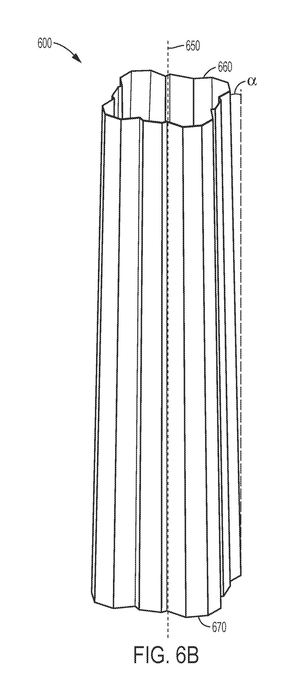
D00013
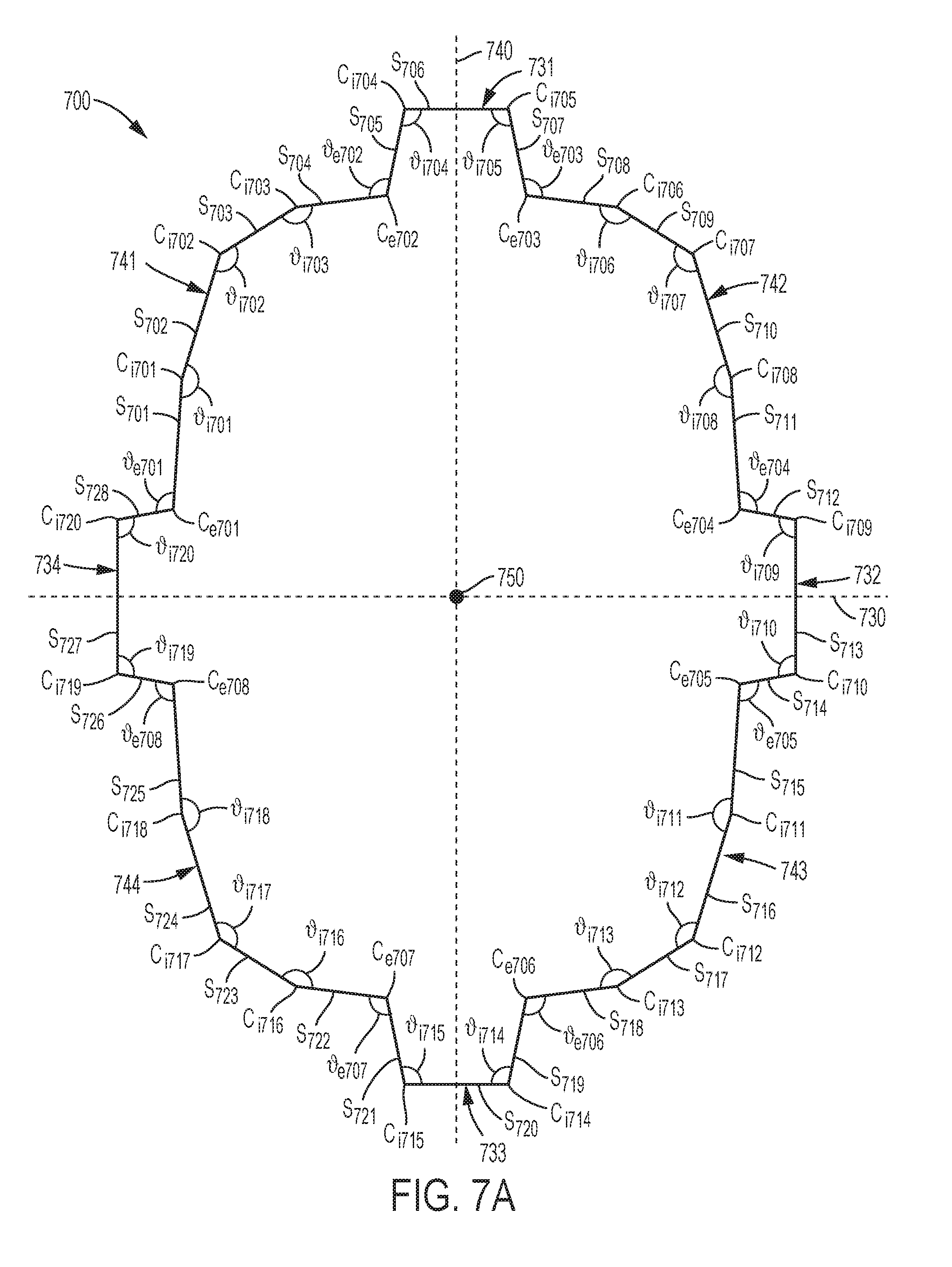
D00014
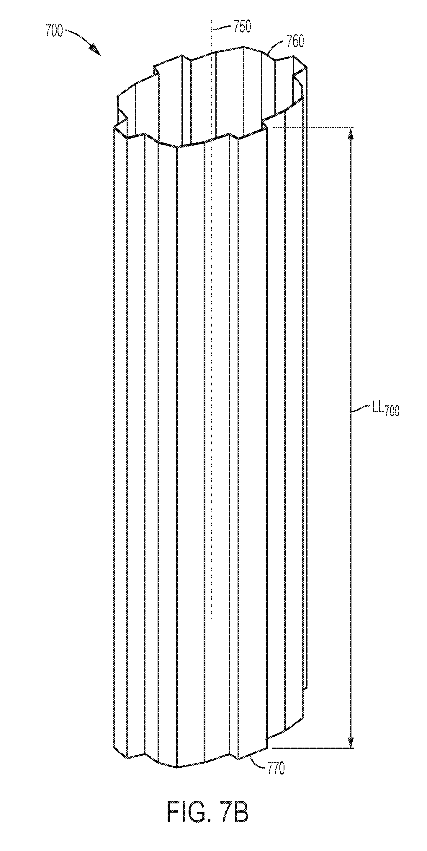
D00015
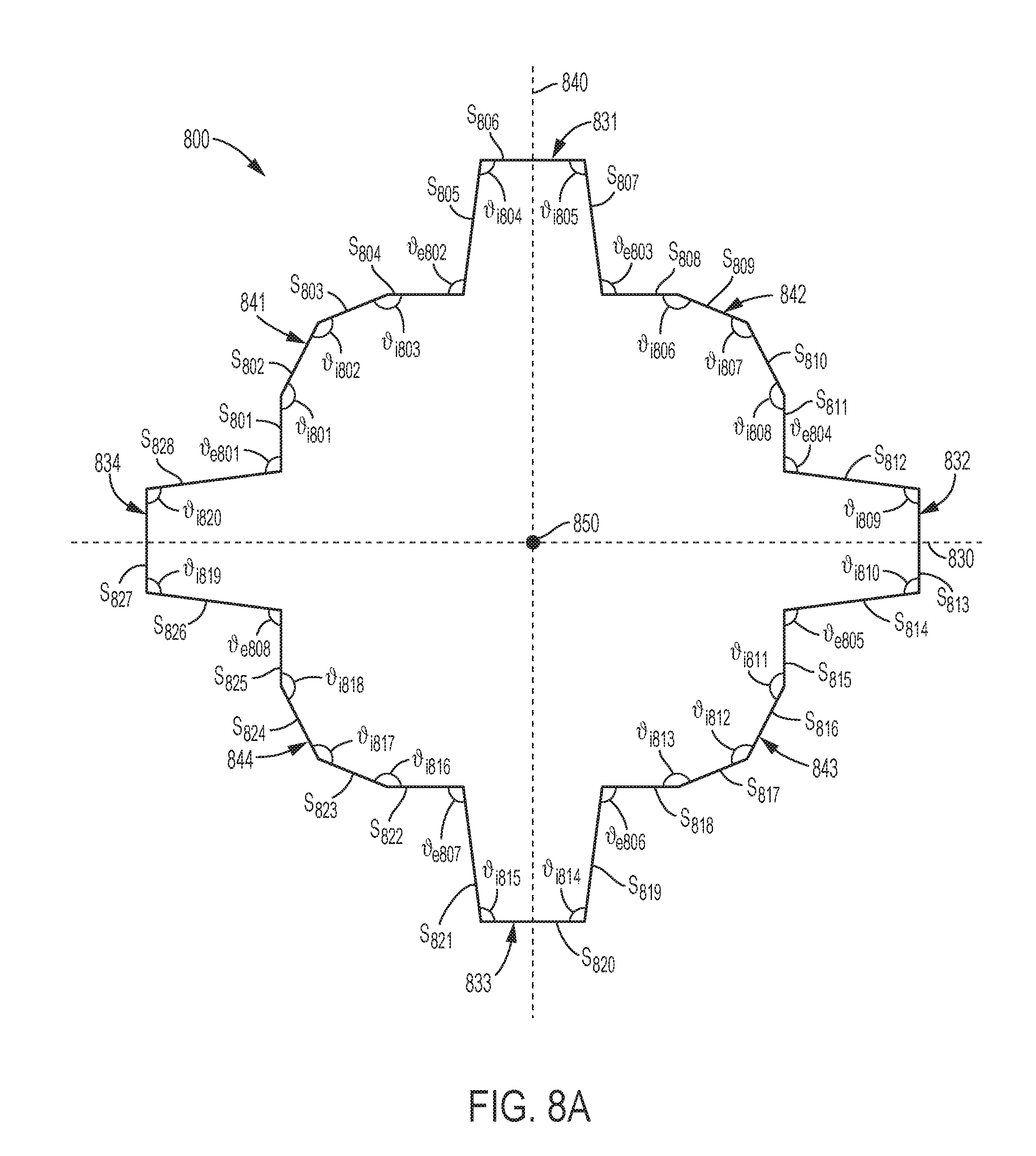
D00016
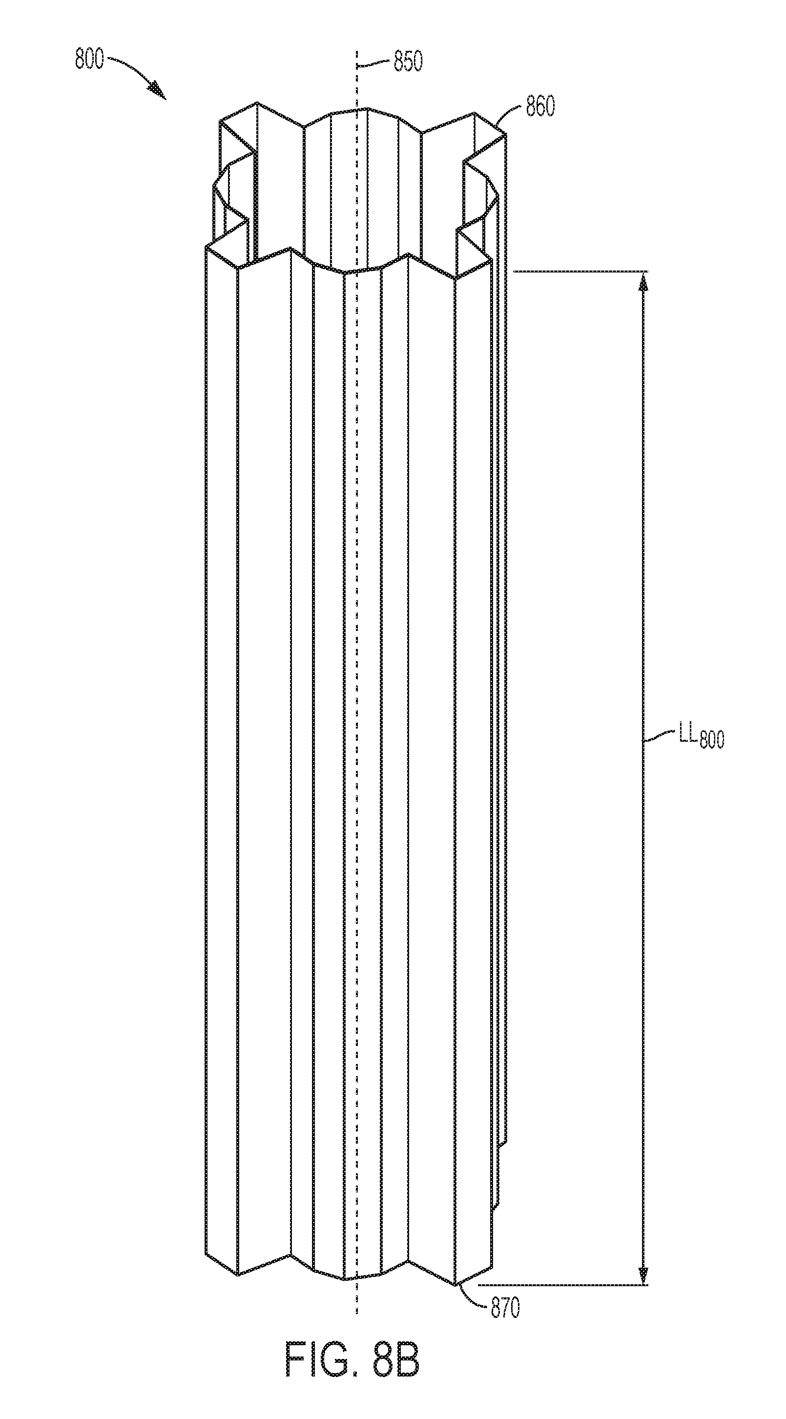
D00017
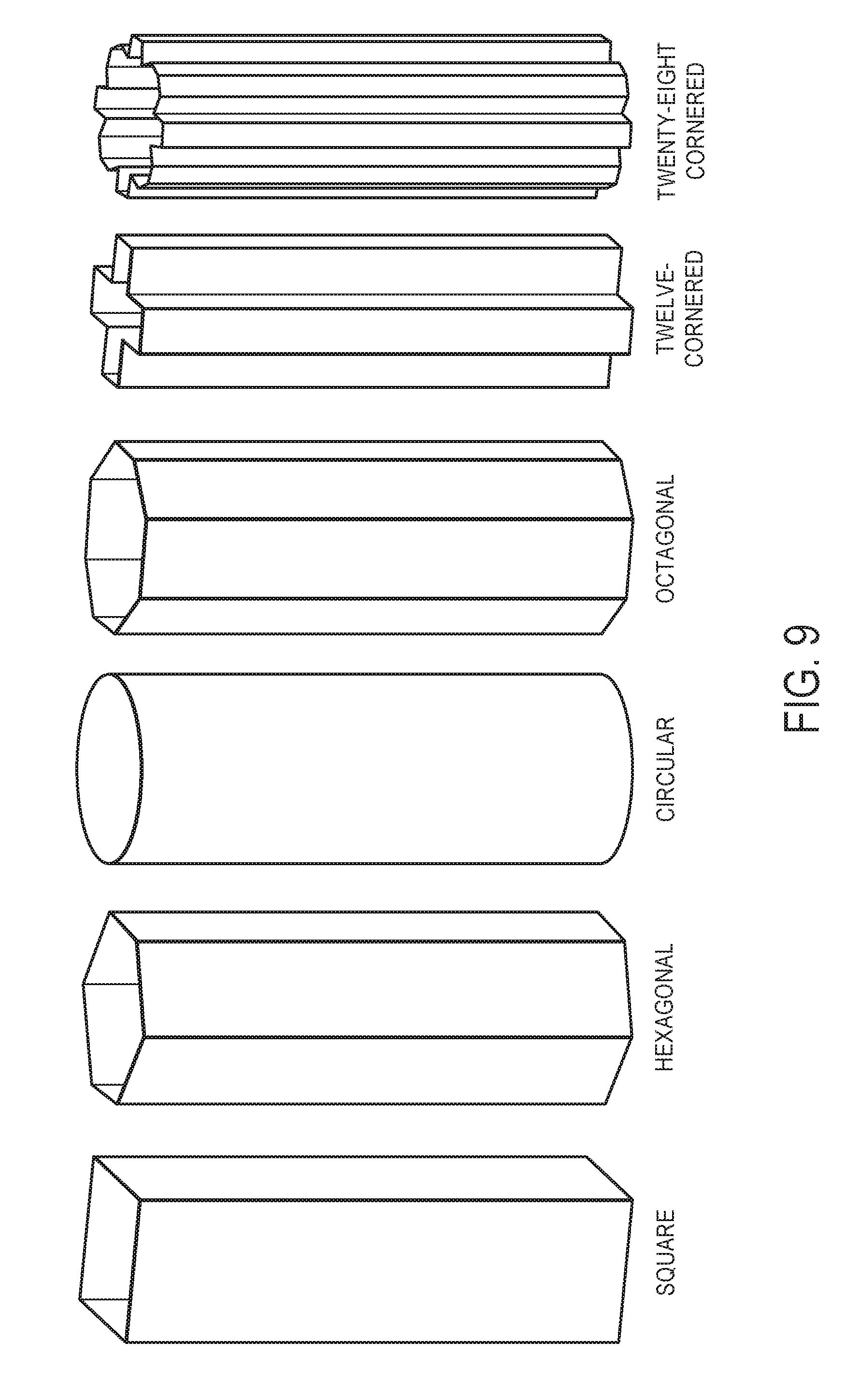
D00018
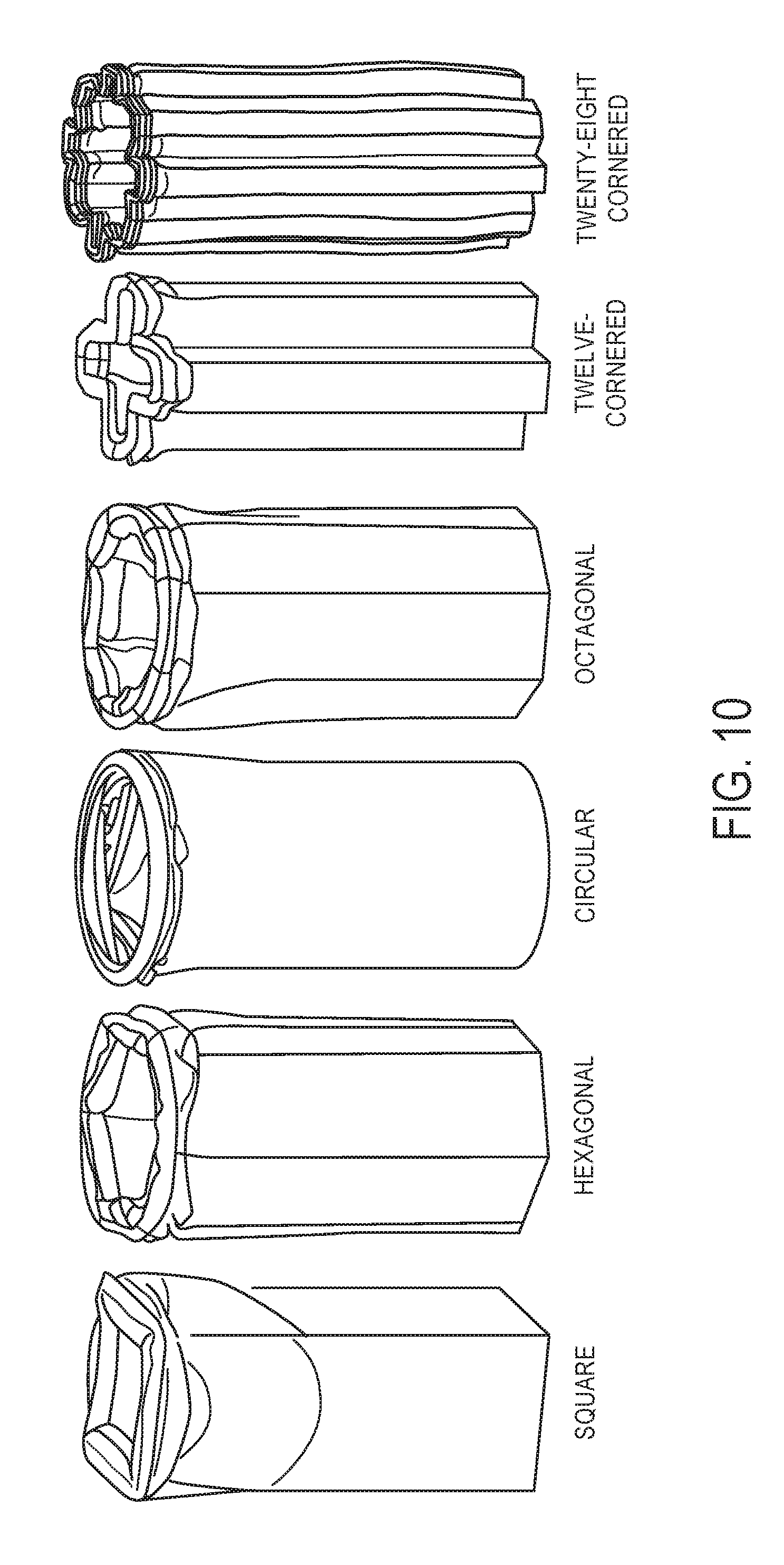
D00019
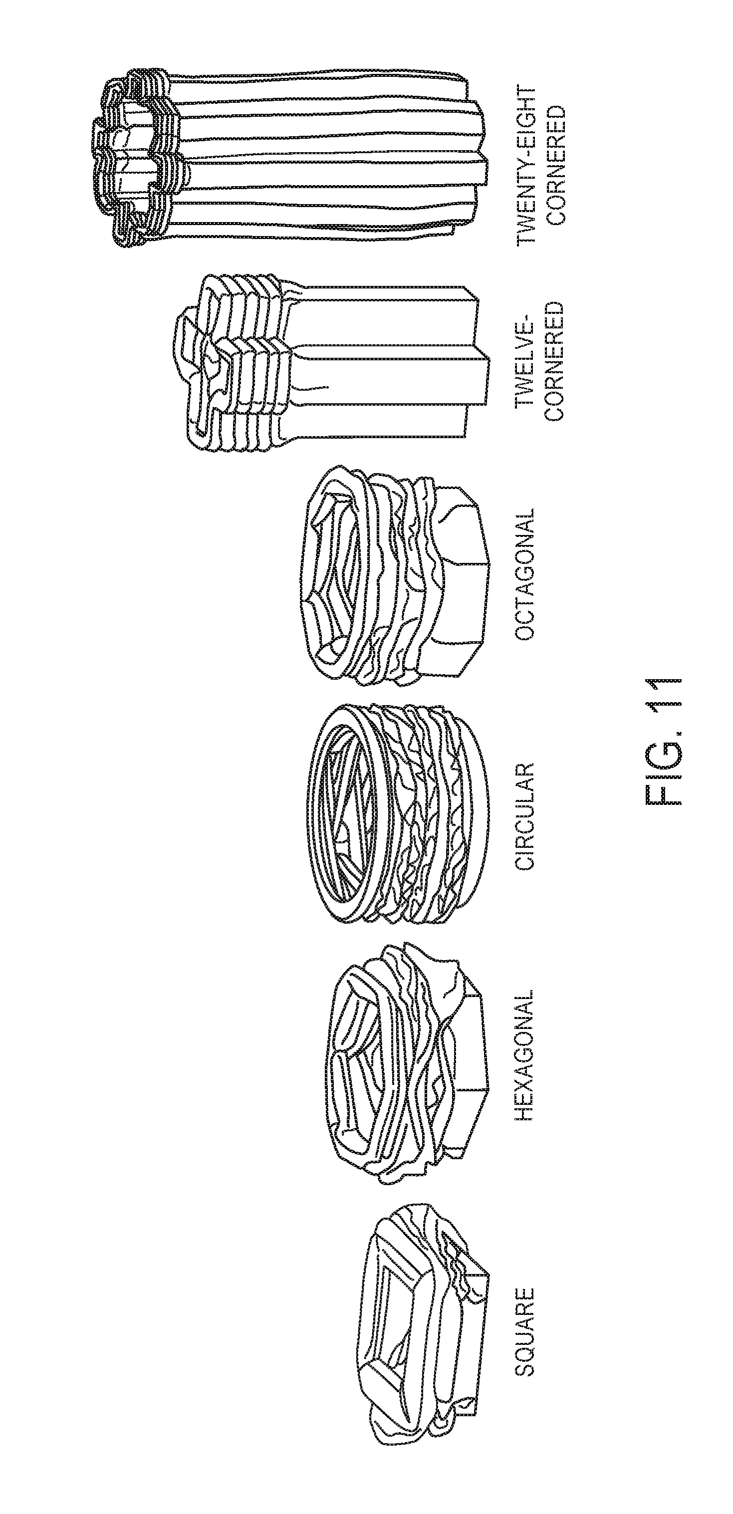
D00020
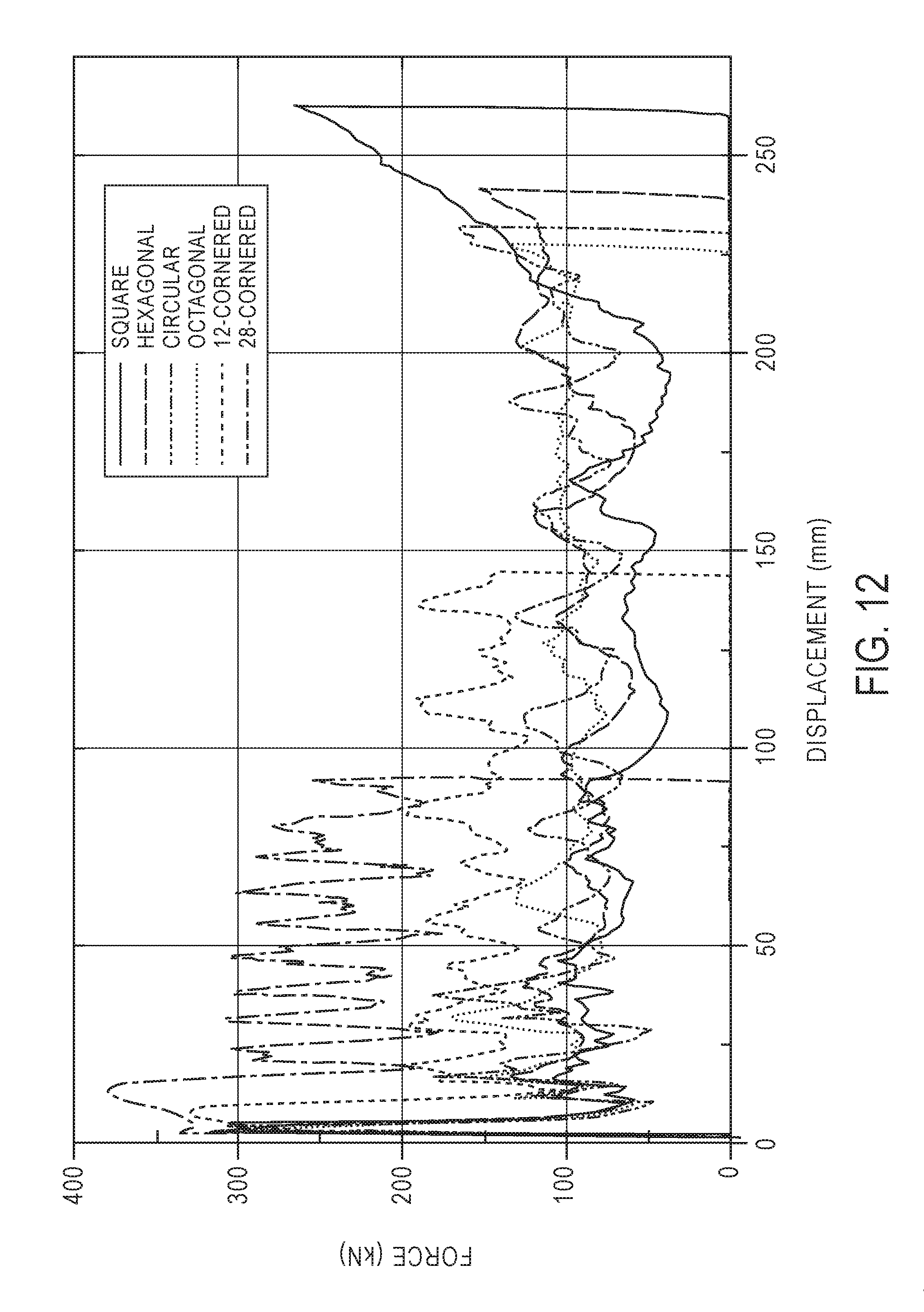
D00021
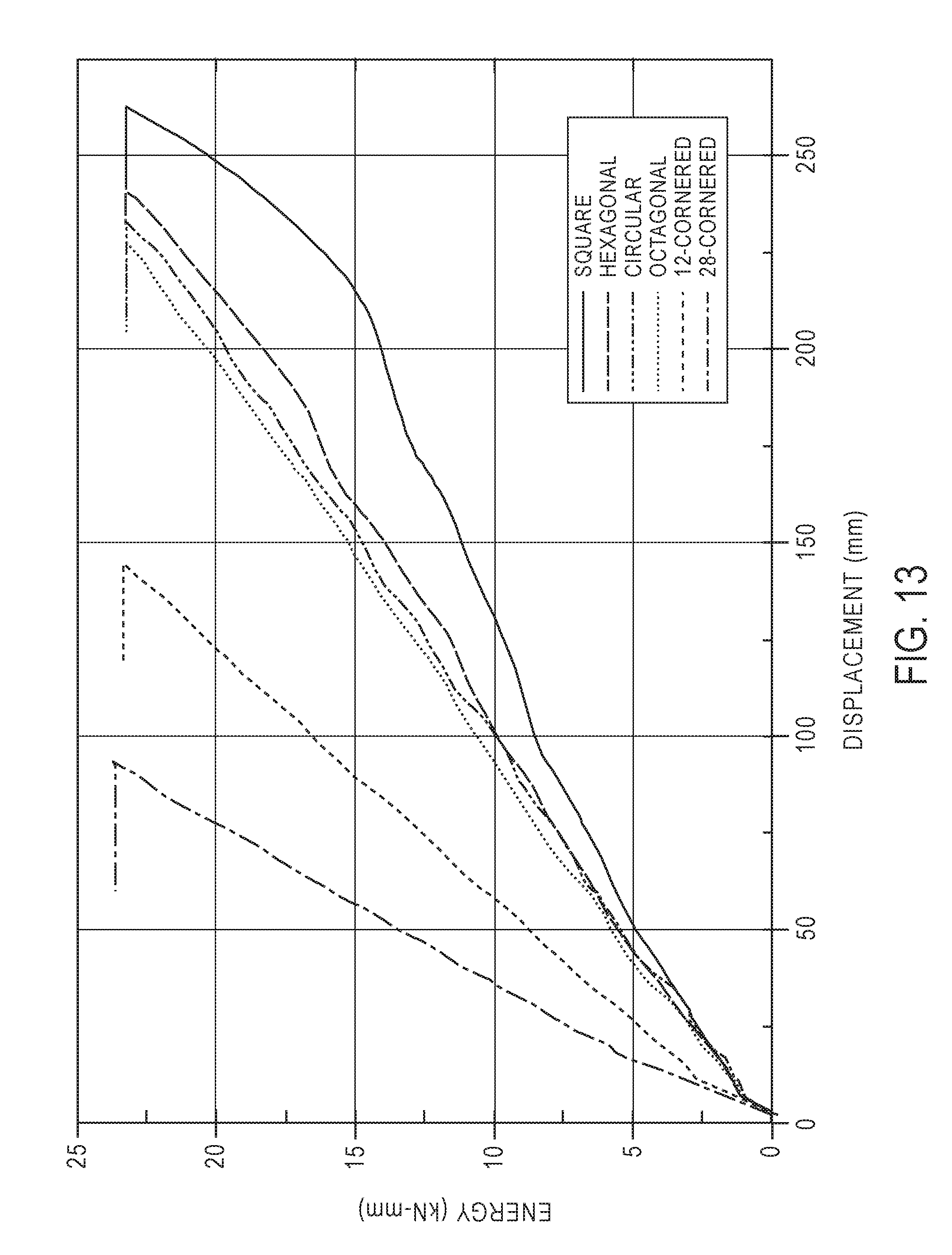
D00022
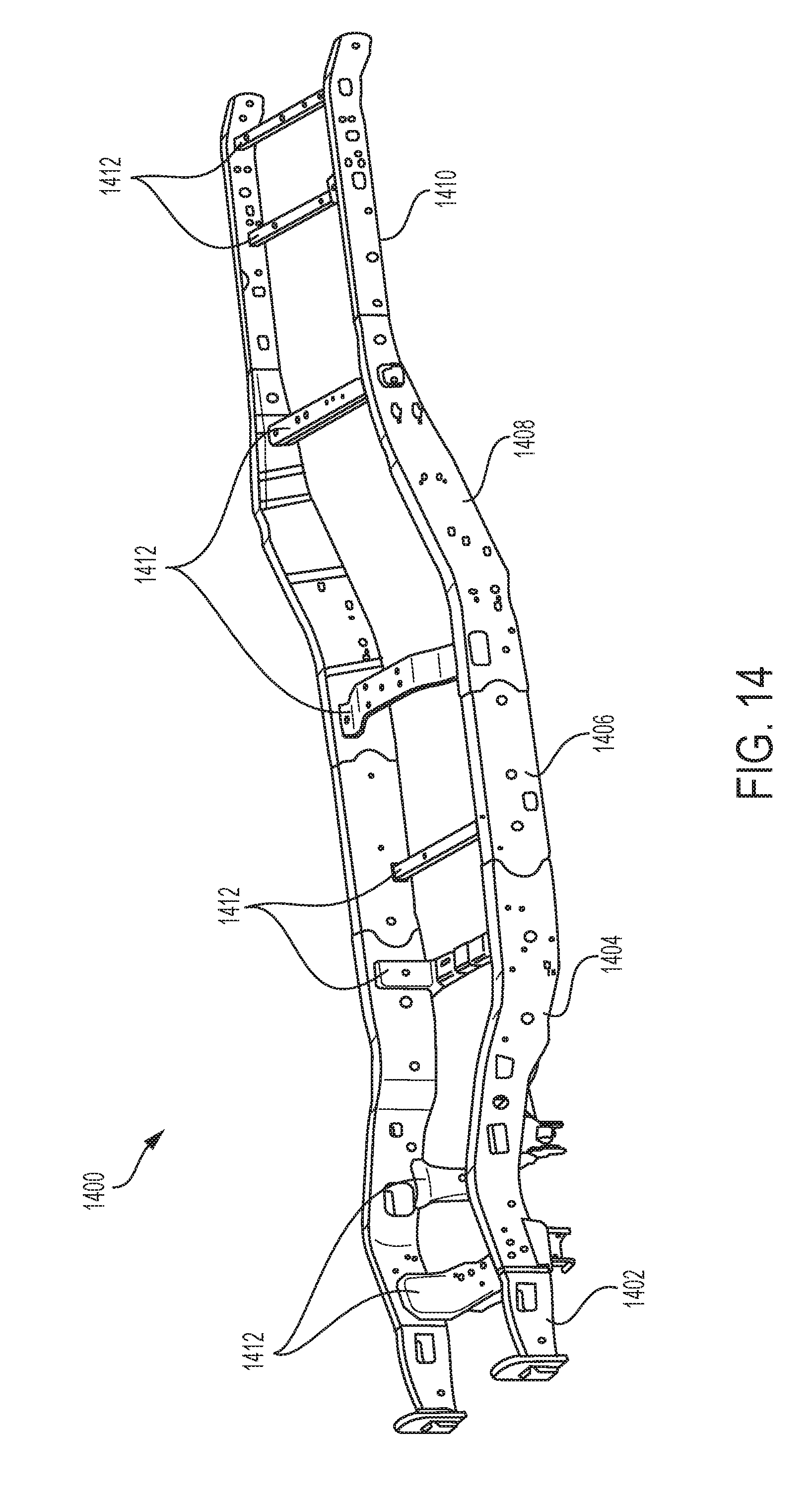
D00023
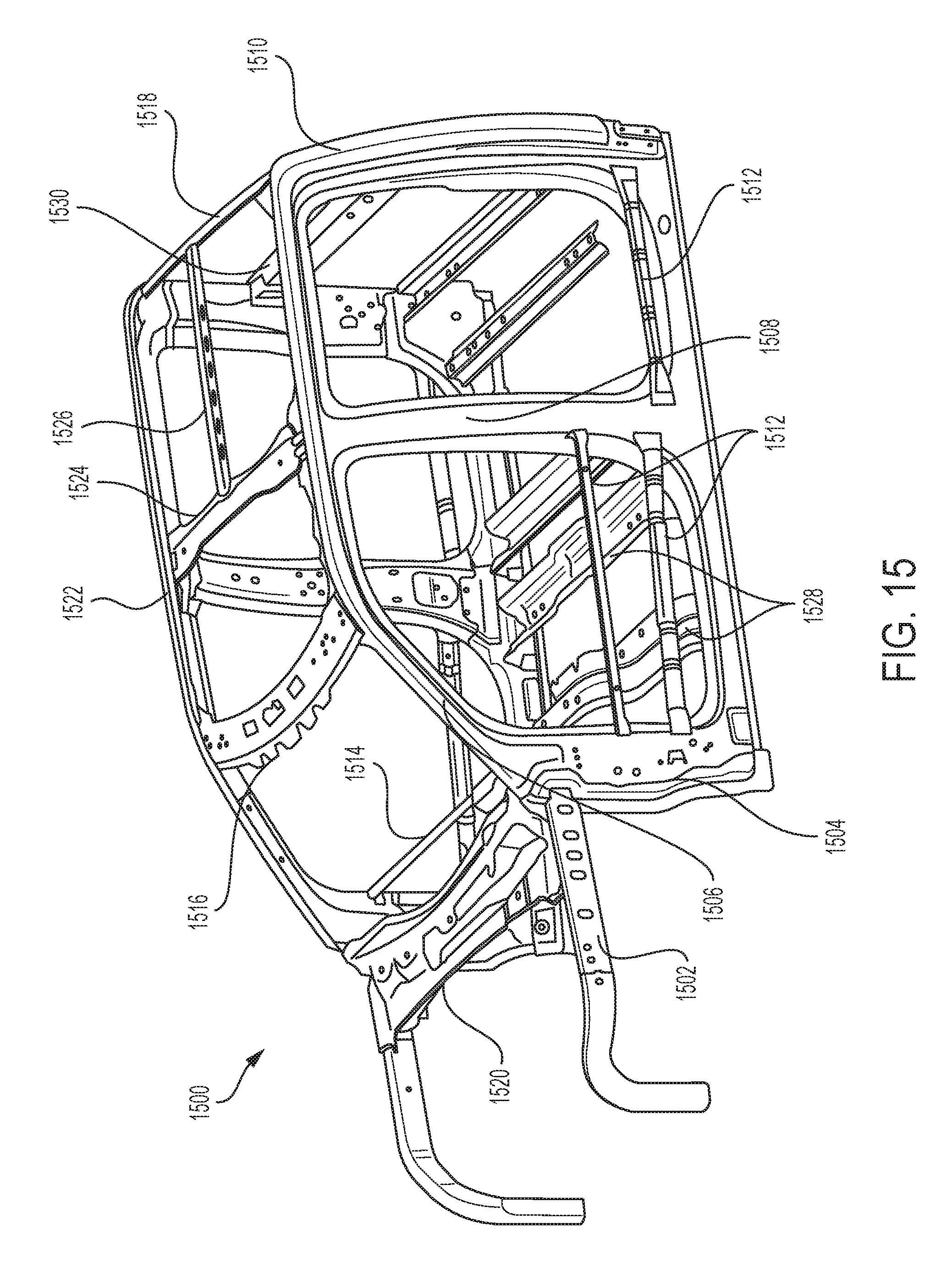
XML
uspto.report is an independent third-party trademark research tool that is not affiliated, endorsed, or sponsored by the United States Patent and Trademark Office (USPTO) or any other governmental organization. The information provided by uspto.report is based on publicly available data at the time of writing and is intended for informational purposes only.
While we strive to provide accurate and up-to-date information, we do not guarantee the accuracy, completeness, reliability, or suitability of the information displayed on this site. The use of this site is at your own risk. Any reliance you place on such information is therefore strictly at your own risk.
All official trademark data, including owner information, should be verified by visiting the official USPTO website at www.uspto.gov. This site is not intended to replace professional legal advice and should not be used as a substitute for consulting with a legal professional who is knowledgeable about trademark law.