Remote manipulator device
Kidd , et al. Ja
U.S. patent number 10,537,713 [Application Number 12/954,648] was granted by the patent office on 2020-01-21 for remote manipulator device. This patent grant is currently assigned to Stereotaxis, Inc.. The grantee listed for this patent is Nathan Kastelein, Brian L. Kidd. Invention is credited to Nathan Kastelein, Brian L. Kidd.


View All Diagrams
| United States Patent | 10,537,713 |
| Kidd , et al. | January 21, 2020 |
Remote manipulator device
Abstract
A system for operating a catheter having a distal end adapted to be navigated in the body, and a proximal end having a handle with a translatable control and a rotatable control for acting on the distal end of the device includes a support for receiving and engaging the handle of the catheter; a translation mechanism for advancing and retracting the support to advance and retract a catheter whose handle is received in the support; a rotation mechanism for rotating the support to rotate a catheter whose handle is received in the support; a translation operator for engaging the translatable control of a catheter whose handle is received in the support and operating the translatable control to act on the distal end of the device; and a rotation operator for engaging the rotatable control of a catheter whose handle is received in the support and operating the rotatable control to act on the distal end of the device.
| Inventors: | Kidd; Brian L. (St. Louis, MO), Kastelein; Nathan (St. Louis, MO) | ||||||||||
|---|---|---|---|---|---|---|---|---|---|---|---|
| Applicant: |
|
||||||||||
| Assignee: | Stereotaxis, Inc. (St. Louis,
MO) |
||||||||||
| Family ID: | 46146188 | ||||||||||
| Appl. No.: | 12/954,648 | ||||||||||
| Filed: | November 25, 2010 |
Prior Publication Data
| Document Identifier | Publication Date | |
|---|---|---|
| US 20110130718 A1 | Jun 2, 2011 | |
Related U.S. Patent Documents
| Application Number | Filing Date | Patent Number | Issue Date | ||
|---|---|---|---|---|---|
| 12786833 | May 25, 2010 | ||||
| 61180926 | May 25, 2009 | ||||
| Current U.S. Class: | 1/1 |
| Current CPC Class: | A61M 25/0113 (20130101); A61M 25/0133 (20130101); A61M 25/0105 (20130101); A61B 34/30 (20160201); A61B 34/35 (20160201); A61B 34/70 (20160201); A61B 2034/302 (20160201); A61M 25/0136 (20130101); A61B 2034/301 (20160201) |
| Current International Class: | A61M 25/092 (20060101); A61M 25/01 (20060101) |
| Field of Search: | ;606/130 ;604/95.01 |
References Cited [Referenced By]
U.S. Patent Documents
| 5353807 | October 1994 | DeMarco |
| 5553198 | September 1996 | Wang et al. |
| 5654864 | August 1997 | Ritter et al. |
| 5707335 | January 1998 | Howard et al. |
| 5779694 | July 1998 | Howard et al. |
| 5814038 | September 1998 | Jensen |
| 5931818 | August 1999 | Werp et al. |
| 6014580 | January 2000 | Blume et al. |
| 6015414 | January 2000 | Werp et al. |
| 6128174 | October 2000 | Ritter et al. |
| 6148823 | November 2000 | Hastings |
| 6152933 | November 2000 | Werp et al. |
| 6157853 | December 2000 | Blume et al. |
| 6212419 | April 2001 | Blume et al. |
| 6241671 | June 2001 | Ritter et al. |
| 6272370 | August 2001 | Gillies et al. |
| 6292678 | September 2001 | Hall et al. |
| 6296604 | October 2001 | Garibaldi et al. |
| 6298257 | October 2001 | Hall et al. |
| 6298259 | October 2001 | Kucharczyk et al. |
| 6304768 | October 2001 | Blume et al. |
| 6311082 | October 2001 | Creighton, IV et al. |
| 6315709 | November 2001 | Garibaldi et al. |
| 6330467 | December 2001 | Creighton, IV et al. |
| 6352363 | March 2002 | Munger et al. |
| 6364823 | April 2002 | Garibaldi et al. |
| 6375606 | April 2002 | Garibaldi et al. |
| 6385472 | May 2002 | Hall et al. |
| 6401723 | June 2002 | Garibaldi et al. |
| 6428551 | August 2002 | Hall et al. |
| 6459924 | October 2002 | Creighton, IV et al. |
| 6474377 | November 2002 | Van De Mortel |
| 6475223 | November 2002 | Werp et al. |
| 6505062 | January 2003 | Ritter et al. |
| 6507751 | January 2003 | Blume et al. |
| 6522909 | February 2003 | Garibaldi et al. |
| 6524303 | February 2003 | Garibaldi |
| 6527782 | March 2003 | Hogg et al. |
| 6529761 | March 2003 | Creighton, IV et al. |
| 6537196 | March 2003 | Creighton, IV et al. |
| 6542766 | April 2003 | Hall et al. |
| 6562019 | May 2003 | Sell |
| 6630879 | October 2003 | Creighton, IV et al. |
| 6662034 | December 2003 | Segner et al. |
| 6677752 | January 2004 | Creighton, IV et al. |
| 6702804 | March 2004 | Ritter et al. |
| 6733511 | May 2004 | Hall et al. |
| 6740103 | May 2004 | Hall et al. |
| 6755816 | June 2004 | Ritter et al. |
| 6786219 | September 2004 | Garibaldi et al. |
| 6817364 | November 2004 | Garibaldi et al. |
| 6834201 | December 2004 | Gillies et al. |
| 6902528 | June 2005 | Garibaldi et al. |
| 6911026 | June 2005 | Hall et al. |
| 6940379 | September 2005 | Creighton |
| 6968846 | November 2005 | Viswanathan |
| 6975197 | December 2005 | Creighton, IV |
| 6980843 | December 2005 | Eng et al. |
| 7008418 | March 2006 | Hall et al. |
| 7010338 | March 2006 | Ritter et al. |
| 7017584 | March 2006 | Garibaldi et al. |
| 7019610 | March 2006 | Creighton, IV et al. |
| 7020512 | March 2006 | Ritter et al. |
| 7066924 | June 2006 | Garibaldi et al. |
| 7137976 | November 2006 | Ritter et al. |
| 7161453 | January 2007 | Creighton, IV |
| 7189198 | March 2007 | Harburn et al. |
| 7190819 | March 2007 | Viswanathan |
| 7211082 | May 2007 | Hall et al. |
| 7248914 | July 2007 | Hastings et al. |
| 7264584 | September 2007 | Ritter et al. |
| 7276044 | October 2007 | Ferry et al. |
| 7286034 | October 2007 | Creighton |
| 7305263 | December 2007 | Creighton, IV |
| 7313429 | December 2007 | Creighton, IV et al. |
| 7331967 | February 2008 | Lee |
| 7341063 | March 2008 | Garibaldi et al. |
| 7346379 | March 2008 | Eng et al. |
| 7389778 | June 2008 | Sabo et al. |
| 7416335 | August 2008 | Munger |
| 7495537 | February 2009 | Tunay |
| 7505615 | March 2009 | Viswanathan |
| 7516416 | April 2009 | Viswanathan et al. |
| 7537570 | May 2009 | Kastelein |
| 7540288 | June 2009 | Viswanathan et al. |
| 7540866 | June 2009 | Viswanathan et al. |
| 7543239 | June 2009 | Viswanathan et al. |
| 7555331 | June 2009 | Viswanathan |
| 7567233 | July 2009 | Garibaldi et al. |
| 7603905 | October 2009 | Creighton, IV |
| 7623736 | November 2009 | Viswanathan |
| 7625382 | December 2009 | Werp et al. |
| 7627361 | December 2009 | Viswanathan |
| 7630752 | December 2009 | Viswanathan |
| 7635342 | December 2009 | Ferry et al. |
| 7657075 | February 2010 | Viswanathan |
| 7662126 | February 2010 | Creighton, IV |
| 7690619 | April 2010 | Wolfersberger |
| 7708696 | May 2010 | Ritter et al. |
| 7742803 | June 2010 | Viswanathan et al. |
| 7747960 | June 2010 | Garibaldi et al. |
| 7751867 | July 2010 | Viswanathan et al. |
| 7756308 | July 2010 | Viswanathan |
| 7757694 | July 2010 | Ritter et al. |
| 7761133 | July 2010 | Viswanathan et al. |
| 7766856 | August 2010 | Ferry et al. |
| 7769428 | August 2010 | Viswanathan et al. |
| 7769444 | August 2010 | Pappone |
| 7771415 | August 2010 | Ritter et al. |
| 7771437 | August 2010 | Hogg et al. |
| 7772950 | August 2010 | Tunay |
| 7774046 | August 2010 | Werp et al. |
| 7815580 | October 2010 | Viswanathan |
| 7818076 | October 2010 | Viswanathan |
| 7831294 | November 2010 | Viswanathan |
| 7853306 | December 2010 | Viswanathan et al. |
| 7892233 | February 2011 | Hall et al. |
| 7927310 | April 2011 | Bencteux et al. |
| 7961924 | June 2011 | Viswanathan |
| 7961926 | June 2011 | Viswanathan |
| 7966059 | June 2011 | Creighton, IV et al. |
| 7983733 | July 2011 | Viswananthan |
| 7998020 | August 2011 | Kidd et al. |
| 8024024 | September 2011 | Viswanathan et al. |
| 8046049 | October 2011 | Govari |
| 8060184 | November 2011 | Hastings et al. |
| 8088129 | January 2012 | Werp et al. |
| 8202244 | June 2012 | Cohen et al. |
| 2001/0038683 | November 2001 | Ritter et al. |
| 2001/0053879 | December 2001 | Mills |
| 2002/0019644 | February 2002 | Hastings et al. |
| 2002/0072704 | June 2002 | Mansouri-Ruiz |
| 2002/0100486 | August 2002 | Creighton, IV et al. |
| 2003/0208207 | November 2003 | Layer |
| 2004/0006301 | January 2004 | Sell et al. |
| 2004/0019447 | January 2004 | Shachar |
| 2004/0030244 | February 2004 | Garibaldi et al. |
| 2004/0064153 | April 2004 | Creighton, IV et al. |
| 2004/0133130 | July 2004 | Ferry et al. |
| 2004/0147829 | July 2004 | Segner et al. |
| 2004/0157082 | August 2004 | Ritter et al. |
| 2004/0158972 | August 2004 | Creighton, IV et al. |
| 2004/0186376 | September 2004 | Hogg et al. |
| 2004/0260172 | December 2004 | Ritter et al. |
| 2004/0267106 | December 2004 | Segner et al. |
| 2005/0004585 | January 2005 | Hall et al. |
| 2005/0020911 | January 2005 | Viswanathan et al. |
| 2005/0021063 | January 2005 | Hall et al. |
| 2005/0033162 | February 2005 | Garibaldi et al. |
| 2005/0065435 | March 2005 | Rauch et al. |
| 2005/0096589 | May 2005 | Shachar |
| 2005/0113812 | May 2005 | Viswanathan et al. |
| 2005/0119556 | June 2005 | Gillies et al. |
| 2005/0119687 | June 2005 | Dacey, Jr. et al. |
| 2005/0182315 | August 2005 | Ritter et al. |
| 2005/0203382 | September 2005 | Govari |
| 2005/0256398 | November 2005 | Hastings et al. |
| 2005/0261633 | November 2005 | Khalaj |
| 2005/0273130 | December 2005 | Sell |
| 2006/0025675 | February 2006 | Viswanathan et al. |
| 2006/0025679 | February 2006 | Viswanathan et al. |
| 2006/0025719 | February 2006 | Viswanathan et al. |
| 2006/0036163 | February 2006 | Viswanathan |
| 2006/0041181 | February 2006 | Viswanathan et al. |
| 2006/0041245 | February 2006 | Ferry |
| 2006/0094956 | May 2006 | Viswanathan |
| 2006/0114088 | June 2006 | Shachar |
| 2006/0116633 | June 2006 | Shachar |
| 2006/0144407 | July 2006 | Aliberto et al. |
| 2006/0144408 | July 2006 | Ferry |
| 2006/0161136 | July 2006 | Anderson |
| 2006/0270948 | November 2006 | Viswanathan et al. |
| 2006/0278248 | December 2006 | Viswanathan |
| 2006/0282150 | December 2006 | Olson et al. |
| 2007/0016010 | January 2007 | Creighton, IV et al. |
| 2007/0016131 | January 2007 | Munger et al. |
| 2007/0021731 | January 2007 | Garibaldi et al. |
| 2007/0021742 | January 2007 | Viswanathan |
| 2007/0021744 | January 2007 | Creighton, IV |
| 2007/0032746 | February 2007 | Sell |
| 2007/0038065 | February 2007 | Creighton, IV |
| 2007/0038074 | February 2007 | Ritter et al. |
| 2007/0040670 | February 2007 | Viswanathan |
| 2007/0043455 | February 2007 | Viswanathan et al. |
| 2007/0049909 | March 2007 | Munger |
| 2007/0055124 | March 2007 | Viswanathan et al. |
| 2007/0055291 | March 2007 | Birkmeyer |
| 2007/0060829 | March 2007 | Pappone |
| 2007/0060916 | March 2007 | Pappone |
| 2007/0060962 | March 2007 | Pappone |
| 2007/0060992 | March 2007 | Pappone |
| 2007/0062546 | March 2007 | Viswanathan et al. |
| 2007/0062547 | March 2007 | Pappone |
| 2007/0123070 | May 2007 | Bencteux |
| 2007/0123964 | May 2007 | Davies et al. |
| 2007/0149946 | June 2007 | Viswanathan |
| 2007/0161882 | July 2007 | Pappone |
| 2007/0167720 | July 2007 | Viswanathan |
| 2007/0179492 | August 2007 | Pappone |
| 2007/0197899 | August 2007 | Ritter et al. |
| 2007/0197906 | August 2007 | Ritter |
| 2007/0225558 | September 2007 | Hauck |
| 2007/0225589 | September 2007 | Viswanathan |
| 2007/0233044 | October 2007 | Wallace |
| 2007/0250041 | October 2007 | Werp |
| 2007/0270686 | November 2007 | Ritter et al. |
| 2008/0004595 | January 2008 | Viswanthan |
| 2008/0006280 | January 2008 | Alberto et al. |
| 2008/0009791 | January 2008 | Cohen et al. |
| 2008/0015427 | January 2008 | Kastelein et al. |
| 2008/0015670 | January 2008 | Pappone |
| 2008/0016677 | January 2008 | Creighton, IV |
| 2008/0016678 | January 2008 | Creighton, IV et al. |
| 2008/0039705 | February 2008 | Viswanathan |
| 2008/0039830 | February 2008 | Munger et al. |
| 2008/0045892 | February 2008 | Ferry |
| 2008/0058608 | March 2008 | Garibaldi et al. |
| 2008/0058609 | March 2008 | Garibaldi et al. |
| 2008/0059598 | March 2008 | Garibaldi et al. |
| 2008/0064933 | March 2008 | Garibaldi et al. |
| 2008/0065061 | March 2008 | Viswanathan |
| 2008/0077007 | March 2008 | Hastings et al. |
| 2008/0092993 | April 2008 | Creighton, IV |
| 2008/0097200 | April 2008 | Blume et al. |
| 2008/0114335 | May 2008 | Flickinger et al. |
| 2008/0119824 | May 2008 | Weitzner |
| 2008/0132910 | June 2008 | Pappone |
| 2008/0161790 | July 2008 | Dando et al. |
| 2008/0200913 | August 2008 | Viswanathan |
| 2008/0208912 | August 2008 | Garibaldi |
| 2008/0228065 | September 2008 | Viswanathan et al. |
| 2008/0228068 | September 2008 | Viswanathan et al. |
| 2008/0243064 | October 2008 | Stahler |
| 2008/0287909 | November 2008 | Viswanathan et al. |
| 2008/0294232 | November 2008 | Viswanathan |
| 2008/0312673 | December 2008 | Viswanathan et al. |
| 2008/0319303 | December 2008 | Sabo et al. |
| 2009/0012821 | January 2009 | Besson et al. |
| 2009/0054835 | February 2009 | Anderson |
| 2009/0062646 | March 2009 | Creighton et al. |
| 2009/0082722 | March 2009 | Munger et al. |
| 2009/0105579 | April 2009 | Garibaldi |
| 2009/0105639 | April 2009 | Weitzner et al. |
| 2009/0131798 | May 2009 | Minar et al. |
| 2009/0131927 | May 2009 | Kastelein et al. |
| 2009/0138009 | May 2009 | Viswanathan et al. |
| 2009/0177037 | July 2009 | Sabo et al. |
| 2009/0306643 | December 2009 | Pappone et al. |
| 2010/0063385 | March 2010 | Garibaldi et al. |
| 2010/0069733 | March 2010 | Kastelein et al. |
| 2010/0097315 | April 2010 | Garibaldi et al. |
| 2010/0137706 | June 2010 | Viswanathan |
| 2010/0163061 | July 2010 | Creighton |
| 2010/0168549 | July 2010 | Pappone |
| 2010/0174234 | July 2010 | Werp et al. |
| 2010/0185212 | July 2010 | Sholev |
| 2010/0222669 | September 2010 | Flickinger et al. |
| 2010/0298845 | November 2010 | Kidd et al. |
| 2010/0305502 | December 2010 | Ferry et al. |
| 2011/0022029 | January 2011 | Viswanathan |
| 2011/0028894 | February 2011 | Foley et al. |
| 2011/0028989 | February 2011 | Ritter et al. |
| 2011/0033100 | February 2011 | Viswanathan |
| 2011/0040150 | February 2011 | Govari et al. |
| 2011/0046618 | February 2011 | Minar et al. |
| 2011/0087237 | April 2011 | Viswanathan |
| 2011/0130718 | June 2011 | Kidd et al. |
| 2011/0152712 | June 2011 | Cao et al. |
| 0 839 547 | Sep 2003 | EP | |||
| 2002522105 | Jul 2002 | JP | |||
| 2007527296 | Sep 2007 | JP | |||
| 2008513057 | May 2008 | JP | |||
| 2008264557 | Nov 2008 | JP | |||
Other References
|
Magnetic Manipulation Instrumentation for Medical Physics Research Authors: G. T. Gillies, r. C. Ritter, W. C. Broaddus, M. S. Grady, M. A. Howard, III, R. G. McNeil 1994 American Institute of Physics Rev. Sci. Instrum. vol. 65, No. 3, Mar. 1994 pp. 533-562. cited by applicant . International Search Report and Written Opinion for corresponding PCT/US2010/036052 dated Jul. 28, 2010 pp. 11. cited by applicant. |
Primary Examiner: Scherbel; Todd J
Attorney, Agent or Firm: Harness, Dickey & Pierce, P.L.C. Wheelock; Bryan K.
Parent Case Text
CROSS-REFERENCE TO RELATED APPLICATIONS
This application is a continuation-in-part of prior U.S. patent application Ser. No. 12/786,833, filed May 25, 2010, which claims priority to U.S. Provisional Patent Application No. 61/180,926 filed on May 25, 2009. The entire disclosures of the above applications are incorporated herein by reference.
Claims
What is claimed is:
1. A system for operating a delivery sheath for a medical device and a medical device delivered through the delivery sheath, the delivery sheath having a distal end adapted to be navigated in the body, and a proximal end having a handle with a translatable control and a rotatable control for acting on the distal end of the delivery sheath, and a lumen extending through the delivery sheath and the handle for the passage of a medical device therethrough, and the medical device being adapted to extend through the lumen in the delivery sheath and out the distal end, the system comprising: a releasable clamp for engaging the handle of the delivery sheath; a socket for receiving and engaging the releasable clamp on the handle of the delivery sheath; a translation mechanism for advancing and retracting the socket to advance and retract the delivery sheath whose handle is received in the clamp engaged in the socket; a rotation mechanism for rotating the socket to rotate the delivery sheath whose handle is received in the clamp engaged by the socket; a translation operator for engaging the translatable control on the handle of the delivery sheath whose handle is received in the clamp and operating the translatable control relative to the handle to act on the distal end of the delivery sheath; a rotation operator for engaging the rotatable control of the delivery sheath whose handle is received in the clamp and operating the rotatable control relative to the handle to act on the distal end of the delivery sheath; and a medical device advancer for engaging and advancing the medical device at least partly disposed in the lumen of delivery sheath.
2. The system according to claim 1 wherein the advancer is top loading to allow the medical device to be introduced into and removed from the advancer at any point intermediate its proximal and distal ends.
3. A system for operating a delivery sheath for a medical device and a medical device delivered through the sheath, the delivery sheath having a distal end adapted to be navigated in the body, and a proximal end having a handle with a translatable control and a rotatable control for acting on the distal end of the delivery sheath, and a lumen extending through the delivery sheath and handle for the passage of a portion of the medical device therethrough, and the medical device adapted to extend through the lumen of the sheath and having a distal end adapted to be navigated in the body, and a proximal end having a handle with a translatable control and a rotatable control for acting on the distal end of the medical device, the system comprising: a delivery sheath controller comprising: a first releasable clamp for engaging the handle of the delivery sheath; a first socket for receiving and engaging the first releasable clamp on the handle of the delivery sheath; a first translation mechanism for advancing and retracting the first socket to advance and retract the delivery sheath whose handle is received in the first clamp engaged in the first socket; a first rotation mechanism for rotating the first socket to rotate the delivery sheath whose handle is received in the first clamp engaged in the first socket; a first translation operator for engaging the translatable control of the delivery sheath whose handle is received in the first clamp engaged in the first socket and operating the translatable control relative to the handle to act on the distal end of the delivery sheath; and a first rotation operator for engaging the rotatable control of the delivery sheath whose handle is received in the first socket and operating the rotatable control relative to the handle to act on the distal end of the delivery sheath; and a medical device controller comprising: a second releasable clamp for engaging the handle of the medical device; a second socket for receiving and engaging the second releasable clamp on the handle of the medical device; a second translation mechanism for advancing and retracting the second socket to advance and retract the medical device whose handle is received in the second releasable clamp engaged by the second socket; a second rotation mechanism for rotating the second socket to rotate the medical device whose handle is received in the second releasable clamp engaged by the second socket; a second translation operator for engaging the translatable control of the medical device whose handle is received in the second releasable clamp engaged in the second socket and operating the translatable control relative to the handle of the medical device to act on the distal end of the medical device; and a second rotation operator for engaging the rotatable control of the medical device whose handle is received in the second releasable clamp engaged in the second socket and operating the rotatable control relative to the handle of the medical device to act on the distal end of the medical device.
Description
BACKGROUND
This section provides background information related to the present disclosure which is not necessarily prior art.
This invention relates to automating the operation of medical devices.
Significant progress has been made in automating the navigation of medical devices in the body. Remote navigation systems, such as the Niobe.RTM. magnetic navigation system available from Stereotaxis, Inc., St. Louis, Mo., allows a physician to remotely orient the distal end of a medical device in the body. More recently, an automated advancer for advancing and retracting the device in the body has also become available, allowing more fully automated catheter navigation systems. However, a practical means of completely automating (under the supervision of a physician) the operation of medical devices, whereby a medical device can be automatically navigated to a particular location and then operated to perform some diagnostic or therapeutic procedure has not been available. This is particularly true with respect to automating the operation of conventional manually operated medical devices.
SUMMARY
This section provides a general summary of the disclosure, and is not a comprehensive disclosure of its full scope or all of its features.
Embodiments of the present invention provide a remote manipulator that not only can manipulate a conventional catheter, but can operate its controls. This not only allows the catheter to be remotely navigated, but also to be remotely operated. This allows a physician to conduct the procedure away from the patient, and also permits the complete automation of the procedure, with a computer navigating the catheter and operating the catheter without the need for human intervention.
Further areas of applicability will become apparent from the description provided herein. The description and specific examples in this summary are intended for purposes of illustration only and are not intended to limit the scope of the present disclosure.
DRAWINGS
The drawings described herein are for illustrative purposes only of selected embodiments and not all possible implementations, and are not intended to limit the scope of the present disclosure.
FIG. 1 is a front perspective view of a preferred embodiment of a remote manipulator device in accordance with the principles of this invention;
FIG. 2 is a rear perspective view of the preferred embodiment of the remote manipulator device, with the drive cables removed for clarity;
FIG. 3 is a top plan view of the preferred embodiment of the remote manipulator device, with the drive cables removed for clarity;
FIG. 4 is a rear elevation view of the preferred embodiment of the remote manipulator device, with the drive cables removed for clarity;
FIG. 5 is a left side elevation view of the preferred embodiment of the remote manipulator device, with the drive cables removed for clarity;
FIG. 6 is an exploded view of the preferred embodiment of the remote manipulator device;
FIG. 7 is a front perspective view of the preferred embodiment of the remote manipulator device, with the device driver removed for clarity;
FIG. 8 is a rear perspective view of the preferred embodiment of the remote manipulator device, with the device driver removed for clarity;
FIG. 9 is a left side elevation view of the preferred embodiment of the remote manipulator device, with the device driver removed for clarity;
FIG. 10 is a top plan view of the preferred embodiment of the remote manipulator device, with the device driver removed for clarity;
FIG. 11 is a front elevation view of the preferred embodiment of the remote manipulator device, with the device driver removed for clarity;
FIG. 12 is a rear perspective view of the preferred embodiment, with the cover removed from the controller;
FIG. 13 is a perspective view of the device driver of the preferred embodiment;
FIG. 14 is a side elevation view of the device driver of the preferred embodiment;
FIG. 15 is an front end elevation view of the device driver of the preferred embodiment;
FIG. 16 is a rear end elevation view of the device driver of the preferred embodiment;
FIG. 17 is a top plan view of the device driver of the preferred embodiment;
FIG. 18 is a perspective view of the body of the device driver, with the upper and lower members separated to show the details of construction;
FIG. 19 is a perspective view of the body of the device driver, with the upper member removed to show the details of construction;
FIG. 20 is an exploded perspective view of the body of the device driver, with the upper member removed;
FIG. 21 is an exploded perspective view of the body of the device driver, with parts removed to show details of construction;
FIG. 22 is a perspective view of the device interface of the preferred embodiment;
FIG. 23 is a top plan view of the device interface of the preferred embodiment;
FIG. 24 is a side elevation view of the device interface of the preferred embodiment;
FIG. 25 is a bottom plan view of the device interface of the preferred embodiment;
FIG. 26 is an exploded perspective view of the device interface of the preferred embodiment;
FIG. 27 is a perspective view of one of the clamps used in the device interface of the preferred embodiment;
FIG. 28 is a rear elevation view of the clamp;
FIG. 29 is a front elevation view of the clamp;
FIG. 30 is a top plan view of the clamp;
FIG. 31 is a side elevation view of the clamp, showing the hinged connection between the base and cover;
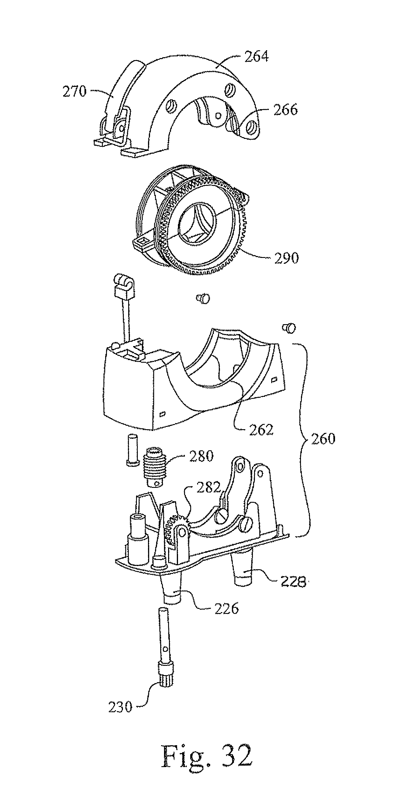
FIG. 32 is an exploded perspective view of the clamp;
FIG. 33 is a perspective view of the split ring adapter used in the clamp;
FIG. 34 is a front elevation view of the split ring adapter;
FIG. 35 is a side elevation view of the split ring adapter;
FIG. 36 is an exploded perspective view of the split ring adapter;
FIG. 37 is a perspective view showing the support installed on the bed;
FIG. 38 is a perspective view showing the mounting of the bracket and controller on the base plate of the support;
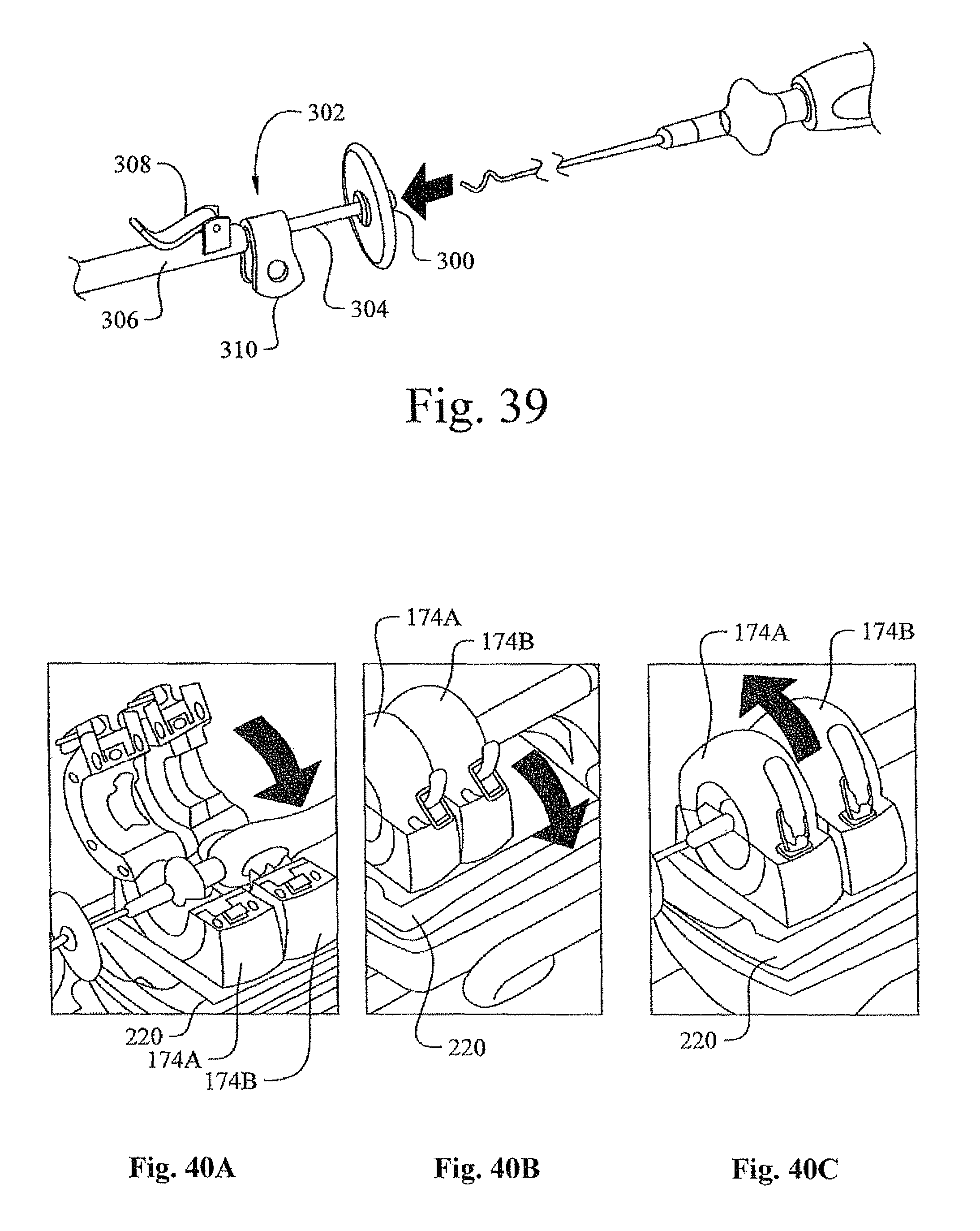
FIG. 39 is a perspective view of the proximal end of a telescoping catheter support;
FIG. 40A is a perspective view of a medical device being placed in the clamps;
FIG. 40B is a perspective view of the covers of the clamps being closed over a medical device being placed in the clamps;
FIG. 40C is a perspective view of the covers of the clamps being latched to secure a medical device being placed in the clamps;
FIG. 41 is a perspective view of an alternative arrangement of the preferred embodiment of the remote manipulator device, adapted for rotating a sheath and advancing a medical device through the rotating sheath,
FIG. 42 is a perspective view of the alternative arrangement of FIG. 41, with the clamp open to show engagement with the sheath;
FIG. 43 is a perspective view of the rotating and advancing mechanism of the alternative arrangement of the preferred embodiment shown in FIG. 41;
FIG. 44 is a perspective view of an alternate arrangement of the remote manipulator of the preferred embodiment for rotating, operating and advancing a manipulable sheath, and for advancing and retracting an elongate medical device in the lumen of the manipulable sheath;
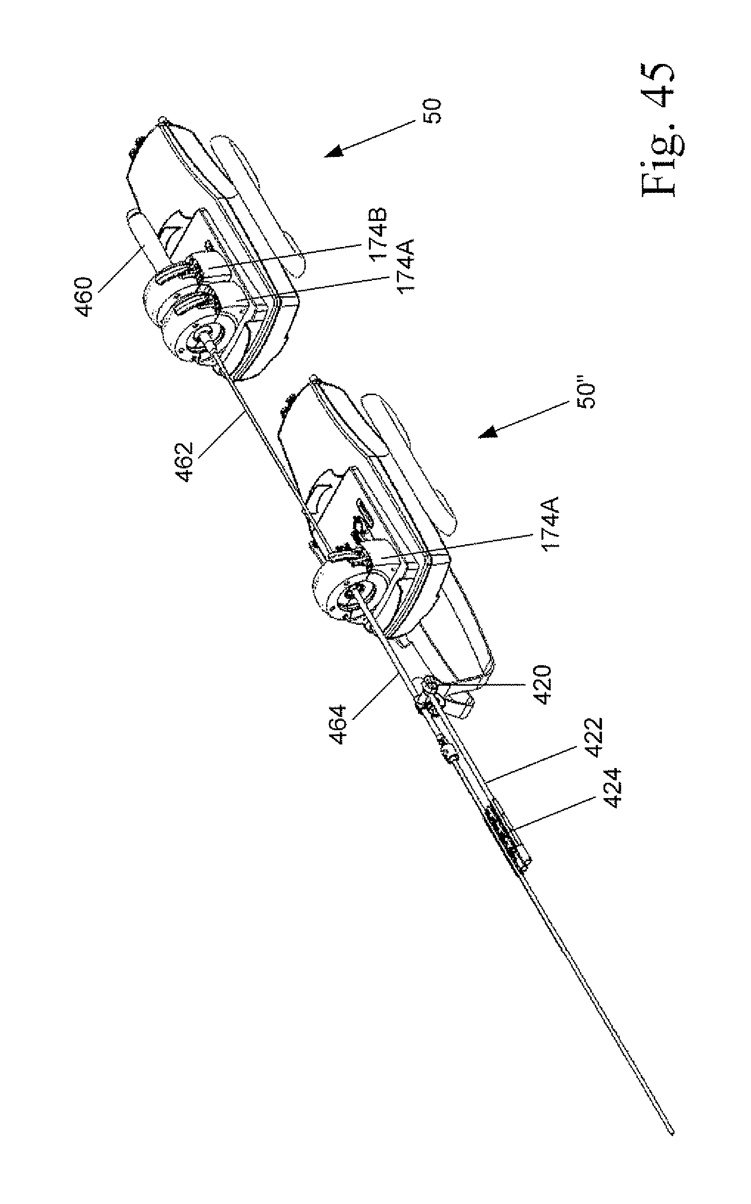
FIG. 45 is a perspective view of an alternate arrangement of the remote manipulator of the preferred embodiment for rotating and advancing a sheath and for operating and advancing an elongate medical device in the lumen of the sheath;
FIG. 46 is a perspective view of an alternate arrangement of the remote manipulator of the preferred embodiment for rotating, operating and advancing a manipulable sheath, and for operating and advancing an elongate medical device in the lumen of the manipulable sheath; and
FIG. 47 is a side elevation view of an alternate arrangement of the remote manipulator of FIG. 46.
Corresponding reference numerals indicate corresponding parts throughout the several views of the drawings.
DETAILED DESCRIPTION
Example embodiments will now be described more fully with reference to the accompanying drawings.
A preferred embodiment of a remote manipulator device constructed according to the principles of this invention is indicated generally as 50 in FIGS. 1-5. The remote manipulator 50 is adapted to engage and operate a medical device. The medical device may be, for example, an electrophysiology catheter of the type comprising an elongate sheath having a handle at its proximal end, and an electrophysiology wire extending through the sheath and out the distal end, forming a loop. The handle preferably has controls for manipulating the distal end of the wire, for example a translatable control for bending the distal end, and a rotatable control for expanding and contracting the loop. While this preferred embodiment is described with respect to an electrophysiology catheter, this invention is not limited to electrophysiology catheters and applies to any medical device with an elongate portion, and a handle at the proximal end that can be manipulated to position and operate the distal end of the elongate portion of the medical device.
As shown in the FIGS. 1-5, the remote manipulator 50 comprises a device driver 52 for mounting and operating a device interface 54 (not shown in FIGS. 1-5), which in this preferred embodiment is both replaceable and disposable. The device driver 52 is mounted on the distal end of an articulated arm 56, whose proximal end is mounted on a post 58 on bracket 60. A controller 62, which can be mounted to the bracket 60, is connected to the device driver 52 by a plurality of flexible drive cables 64 to operate the device driver 52. A platform 66, attachable to the patient bed (not shown in FIGS. 1-5), can mount the bracket 60 and/or the controller 62.
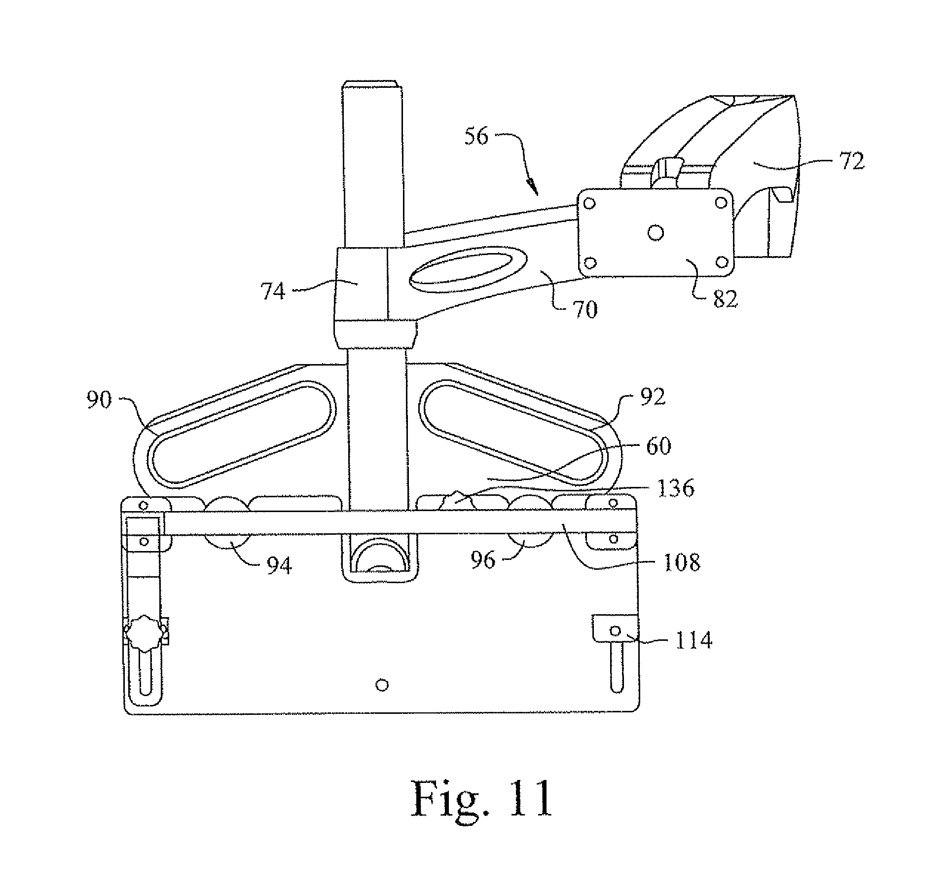
As shown in FIG. 6-11, the articulated arm 56 comprises proximal and distal sections 70 and 72. Proximal section 70 has a collar 74 at its proximal end for mounting the proximal section 70 on the post 58. The proximal section 70 can translate up and down, and rotate around, the post 58. A locking screw 76 allows the collar and thus, the proximal section 70 to be releasably locked relative to the post 58. The distal end of the proximal section 70 is pivotally connected to the proximal end of the distal section 72. A lock (not shown) can be provided to releasably lock the proximal and distal sections 70 and 72 relative to each other. A first wrist element 78 is pivotally mounted to the distal end of the distal section 72 to pivot about a first axis generally perpendicular to the longitudinal axis of the distal section. A second wrist element 80 is pivotally mounted to the first wrist element to pivot about a second axis generally perpendicular to the first axis. A mounting plate 82 is rotatably mounted to the second wrist element 80 to rotate about a third axis, perpendicular to the first axis. The wrists pivoting about the first and second axis and the mounting plate rotating about the third axis are selectively releasably lockable, to releasably secure the articulated arm in a desired configuration with the device driver 52 in a desired location.
As also shown in FIGS. 6-11, the bracket 60 has hand loops 90 and 92 thereon. Pins 94 and 96 with enlarged conical heads project from the front face of the bracket 60. There is a semi-circular notch 98 in the bottom of the bracket 60.
As also shown in FIGS. 6-11, the platform 66 comprises a base plate 100, and a generally right-triangular frame 102, comprising legs 104 and 106, extending from the base plate 100 and leg 108 extending between the legs 104 and 106. A generally L-shaped bracket 110 telescopes from the leg 104 of the frame 102. Cleats 112 and 114 are mounted in slots 116 and 118 in the base plate 100 with threaded bolts 120 and 122 which have knurled heads that allow the cleats to be tightened against the side rail typically found on a patient bed. Similarly, a cleat 124 is mounted in slot 126 in the end of L-shaped bracket 110 with a threaded bolt 128 with a knurled head that allows the cleat to be tightened against the side rail of the patient bed. The top edge of the base plate 100 has semi-circular notches 130 and 132 for engaging the pins 94 and 96 on the bracket, and the back face of the base plate has a projecting pin 134 for engaging the semi-circular notch 98 in the bracket 60. A bolt 136 on the bracket 60 can be tightened to engage a slot 138 on the base plate 100 to secure the bracket and base plate 100.
The controller 62 can be attached to the bracket 60 and mounted on the platform 66. As shown in FIG. 12, the controller includes a housing 140 with four drives: a drive 142 for operating a first clamp driver on the device driver 52; a drive 144 for operating the second clamp translation driver on the device driver; a drive 146 for operating a second clamp driver on the device driver; and a drive 148 for operating the translation driver on the device driver for translating the device, as will be described in more detail below. Flexible drive cables 64 connect each drive in the controller with its respective driver in the device drive 52.
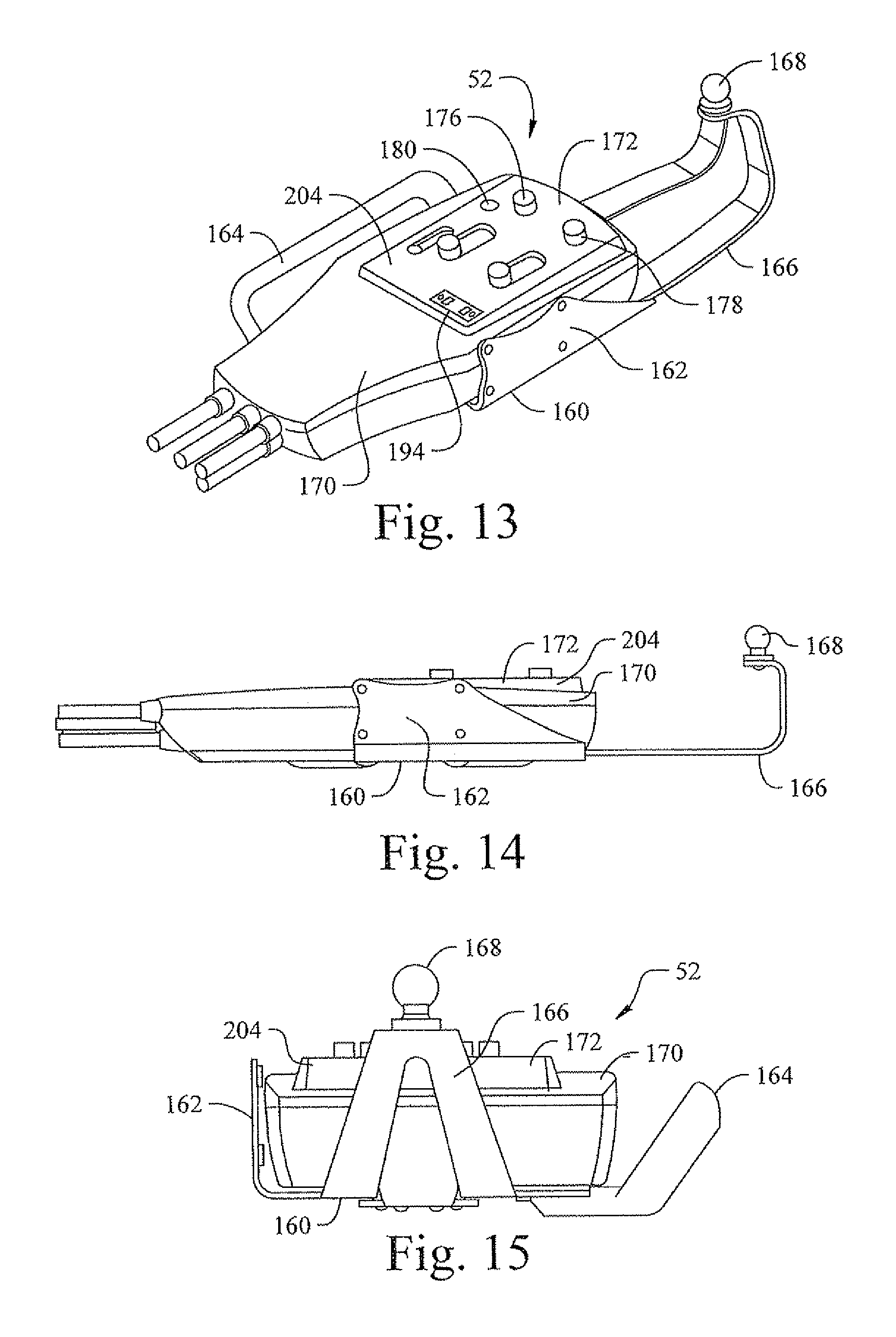
As shown in FIGS. 13-21, the device driver 52 comprises a base 160 having a mount 162 for attaching the device driver to the mounting plate 82 on the end of the articulated arm 56. A hand loop 164 on the opposite side of the base 160 from the mount 162 can be provided for gripping the device driver 52 to reposition it. A generally V-shaped bracket 166 projects from the front of the base 160, the end of the bracket is bent upwardly and has a fixture 168 mounted thereon for mounting a sheath, as described in more detail below. The device driver 52 further comprises a body 170 mounted on the base 160 to translate forwardly and rearwardly with respect to the base.
The top surface of the body 170 has a platform 172 for mounting a device interface 54 thereon. As described below, the device interface 54 has one or more clamps 174 (not shown in FIGS. 13-21) for engaging and operating the handle of an elongate medical device. The platform 172 has a first pair of mounting sockets 176 and 178 for engaging a clamp 174 on the device interface 54, and a drive socket 180 for receiving and engaging a drive shaft of the clamp to operate the clamp. In this preferred embodiment, the platform 172 also has a second pair of mounting sockets 182 and 184 for engaging a second clamp 174 on the device interface 54, and a drive socket 186 for receiving and engaging a drive shaft of the second clamp to operate the second clamp. The second pair of sockets 182 and 184, and the drive socket 186 are disposed in slots so that they can translate relative to the first set of sockets 176 and 178, to accommodate relative movement between the clamps 174 on the device interface 54, as will be described in more detail below. There is an electrical contact pad 194 on the platform 172 for making electrical contact with a corresponding electrical contact pad 196 on the device interface 54.
As shown in detail in FIG. 18, the body 170 comprises upper and lower housing members 200 and 202. The platform 172 is formed in the top of the upper housing member 200, and comprises a raised platform area 204 with openings for the sockets 176 and 178 and 182 and 184, as well as contact pad 194. As shown in FIG. 19, in the lower housing member 202, the distal end of flexible drive cable 64A, connects the drive 142 to a transmission 206 for turning socket 180 to operate a first clamp 174 on a device interface 54 seated on the platform 172. The distal end of a cable 64B connects the drive 144 to a screw-driven translation mechanism 208 for translating the second pair of sockets 182 and 184 relative to first pair or sockets 176 and 178. The distal end of cable 64C connects the drive 146 to a transmission 210 for turning socket 186 to operate a second clamp 174 on a device interface 54. Lastly, a flexible drive cable 64D connects the drive 148 to a screw translation mechanism 212 (FIG. 21) for moving the body 170 relative to the base 160.
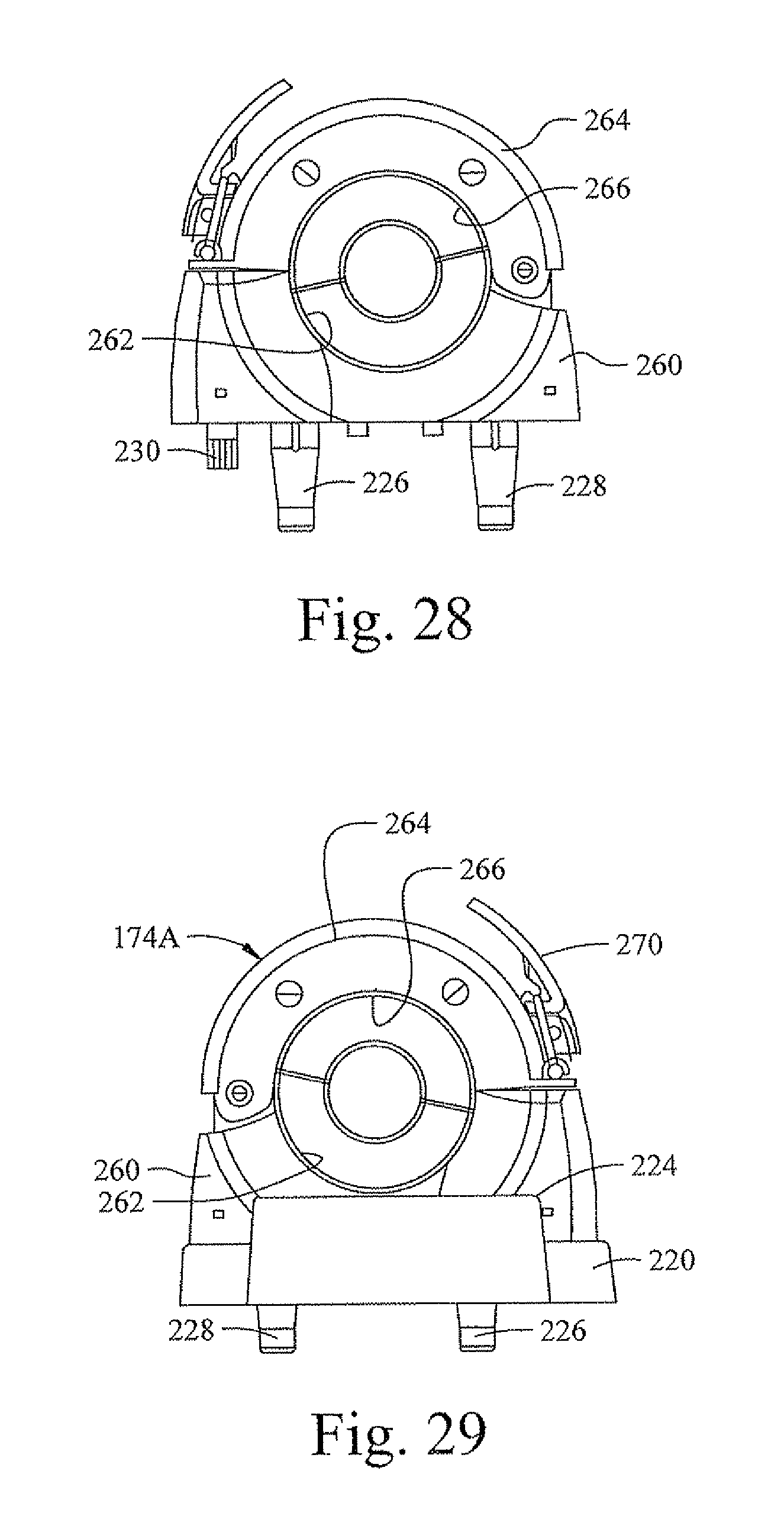
As shown in FIGS. 22-26, the device interface 54 comprises a tray 220 that is adapted to fit onto the raised platform 204 forming the platform 172 on the device driver 52. The tray 220 has a generally rectangular shape, but preferably has a curved side or other feature that prevents the tray from being installed on the device driver 52 incorrectly. There are handles 222 and 224 at either end of the tray 220 to facilitate handling the tray. One or more clamps 174 are mounted on the tray 220. In this preferred embodiment there are two clamps, a first clamp 174A, which is fixedly mounted with respect to the tray 220, and a second clamp 174B, which is slidably mounted with respect to the tray 220. As described in more detail below, each of the clamps has two depending pins 226 and 228, and a depending drive spline 230. The tray 220 has a pair of holes 232 and 234 for receiving the pins 226 and 228 of clamp 174A, and a hole 236 for receiving the drive spline 230. Two mounting holes 238 and 240 allow the clamp 174A to be secured to the tray with screws 242 and washers 244. The tray 220 also has a pair of slots 246 and 248 for receiving the pins 226 and 228 of clamp 174B, and a slot 250 for receiving the drive spline 230. Two mounding slots 252 and 254 allow the clamp 174B to be secured to the tray with screws 242 and washers 244. The slots 246, 248, 250 and 252 and 254 allow the clamp to translate on the tray 220. A contact plate 192 is secured on the bottom of the tray for making electrical contact with the contact pad 194 on the device driver 52.
As shown in FIGS. 27-36, each of the clamps 174 comprises a base 260 which carries the pins 226 and 228 and the drive spline 230. The base 260 has a semi-circular notch 262. A generally arcuate cover 264 has a semi-circular notch 266 therein which is hingedly attached at one end to the base 260, to pivot between an open position and closed position, in which the semi-circular notch 262 in the base 260 and the semi-circular notch 266 in the cover 264 form a generally circular opening 268 through the clamp. An over-center latch 270 releasably secures the other end of the cover 264 to the base 260 to retain the cover in its closed configuration.
As best shown in FIG. 32, a worm gear 280 is mounted on the end of the spline 230 to rotate with the spline. The worm gear engages a sprocket 282, so that the sprocket turns when the spline 230 turns.
A split adapter ring 290 comprises first and second generally semi-circular halves 292 and 294, and has a hinged connection 296 at one side to pivot between an open position and a closed position in which the halves 292 and 294 form a ring. The other ends of the halves 292 and 294 are releasably connected, for example with a snap latch 298 to form a ring with a central opening 300. The split adapter ring 290 can be secured around a portion of the handle of a conventional manually operated medical device. The split adapter ring 290 has an associated ring gear 302 and is adapted to fit inside the clamp 174B, with the ring gear 302 engaged with the sprocket 282. The interior of each of the halves 292 and 294 can be specially adapted to receive the handle of a particular medical device, or various inserts (for example inserts 304 and 306 shown in FIG. 36) can be used to adapt a standardized halves to accommodate different medical devices.
An alternative arrangement of the preferred embodiment of the remote manipulator device indicated as 50' is shown in FIGS. 41-43. The remote manipulator 50' is similar in construction and arrangement to the remote manipulator 50, and corresponding parts are identified with corresponding reference numerals. However instead engaging the handle at the proximal end of a medical device, the remote manipulator 50' is adapted to engage and rotate sheath 402, and engage and advance and retract elongate flexible medical device 404 in the lumen of the sheath
In particular with remote manipulator 50', the clamp 174A of remote manipulator 50 is adapted to engage and rotate a sheath 402 surrounding the proximal portion of the medical device 404. The clamp 174B of remote manipulator 50 has been replaced with a device advancer 406 that engages and advances the proximal portion of the medical device 404 extending from the proximal end of the sheath 402. Thus the clamp 174B can rotate the sheath 402, whose distal end may have a shaped configuration, such as a bend or twist, in order to orient the distal end the medical device 404 as it exits the distal end of the sheath. The device advancer 406 engages the proximal end of the medical device and can advance and retract the medical device through the lumen of the sheath 402.
The device advancer 406 may similar in construction to the device advancer 30 disclosed in U.S. Pat. No. 7,635,342, incorporated herein by reference. Like the device 30 of U.S. Pat. No. 7,632,342, the device advancer 406 is preferably top-loading, allowing the medical device 404 to be introduced into and removed from the advancer at any point intermediate its proximal and distal ends. However, unlike device advancer 30 of U.S. Pat. No. 7,632,342, the device advancer 406 is adapted to mount on the platform 172 and engage and be driven by the device driver 52. As shown in FIG. 43, the advancer has a base particularly adapted to mount on, and be driven by, the platform 172.
The medical device 404 may have a handle at its proximal end that can be manually manipulated to operate the device. The remote manipulator 50' operating to rotate the sheath 402 and to advance and retract the medical device 404 through the lumen of the sheath 402, and the device 404 otherwise being manually operated via its handle. However in order to fully enable remote operation it may be desirable to operate remote manipulator 50' and a remote manipulator 50 that engages the handle of the medical device and can operate it remotely as well.
As shown in FIG. 42, the proximal end of the sheath 402 can have a knurled end 410, or other configuration to ensure that it can be engaged within the clamp 174A and rotated. In the preferred embodiment the sheath 402 comprises a relatively rigid proximal section 412 connected to the knurled end 410, and a relatively more flexible distal section 414, which can be connected to the proximal section with mating connector elements 416 and 418. The distal end of the distal section 414 can have a bend, twist or other configuration to help orient the distal end of medical device 404 as it exits the distal end of the sheath 402. As shown in FIG. 42 an clamp 420 can engage the proximal section of the sheath, and support a rod 422, that in turn supports a bracket 424 that supports the proximal portion of the distal section 414, to reduce undesired bending and flexing of the sheath.
Another alternate arrangement of the remote manipulator of the preferred embodiment is shown in FIG. 44 as it would be arranged for rotating, operating and advancing a manipulable sheath and for advancing and retracting an elongate medical device in the lumen of the manipulable sheath. The remote manipulator 50 engages the handle 450 of a remotely manipulable sheath 452. The remote manipulator 50 can rotate, advance and retract the sheath 452 and operate the controls on the handle 450 to cause the distal end of the sheath to bend or turn. A separate advancer 454 can be provided to advance and retract a medical device 456 through the lumen of the sheath 452. Thus the manipulable sheath 452 can be rotated, advanced and retracted, and operated, and a medical device can be advanced and retracted through the lumen of the manipulable sheath, remotely.
Another alternate arrangement of the remote manipulator of the preferred embodiment is shown in FIG. 45 as it would be arranged for rotating and advancing a sheath and for operating and advancing and retracting a medical device in the lumen of the sheath. The remote manipulator 50 engages the handle 460 on the proximal end of a remotely manipulable medical device 462. The remote manipulator 50 can advance retract the medical device, and operate the controls on the handle 460 to cause the distal end of the medical device 462 to bend or other otherwise operate. For example, in the case of a lasso catheter, operating of the controls can deflect the lasso, and expand and contract the loop of the lasso. The distal end of the elongate medical device extends through the lumen of a sheath 464. The proximal end of the sheath 464 is engaged in the front clamp 174A of a second remote manipulator 50'' which can be identical to manipulator 50, except that the second clamp 174B, which is unnecessary, has be removed. The distal end of the sheath 464 is bent or has some other shape to facilitate navigation, and the remote manipulator 50'' can advance, retract, and rotate the sheath to navigate the distal end of the sheath in the body. The remote operator 50'' and the remote operator 50 can be operated in coordinated manner so that the remote operator 50'' brings the distal end of the sheath 464 to the desired location or orientation, and the remote manipulator 50 advances and retracts the medical device 462 through the lumen of the sheath and out the distal end, and operates the handle 460 to operate the distal end of the medical device.
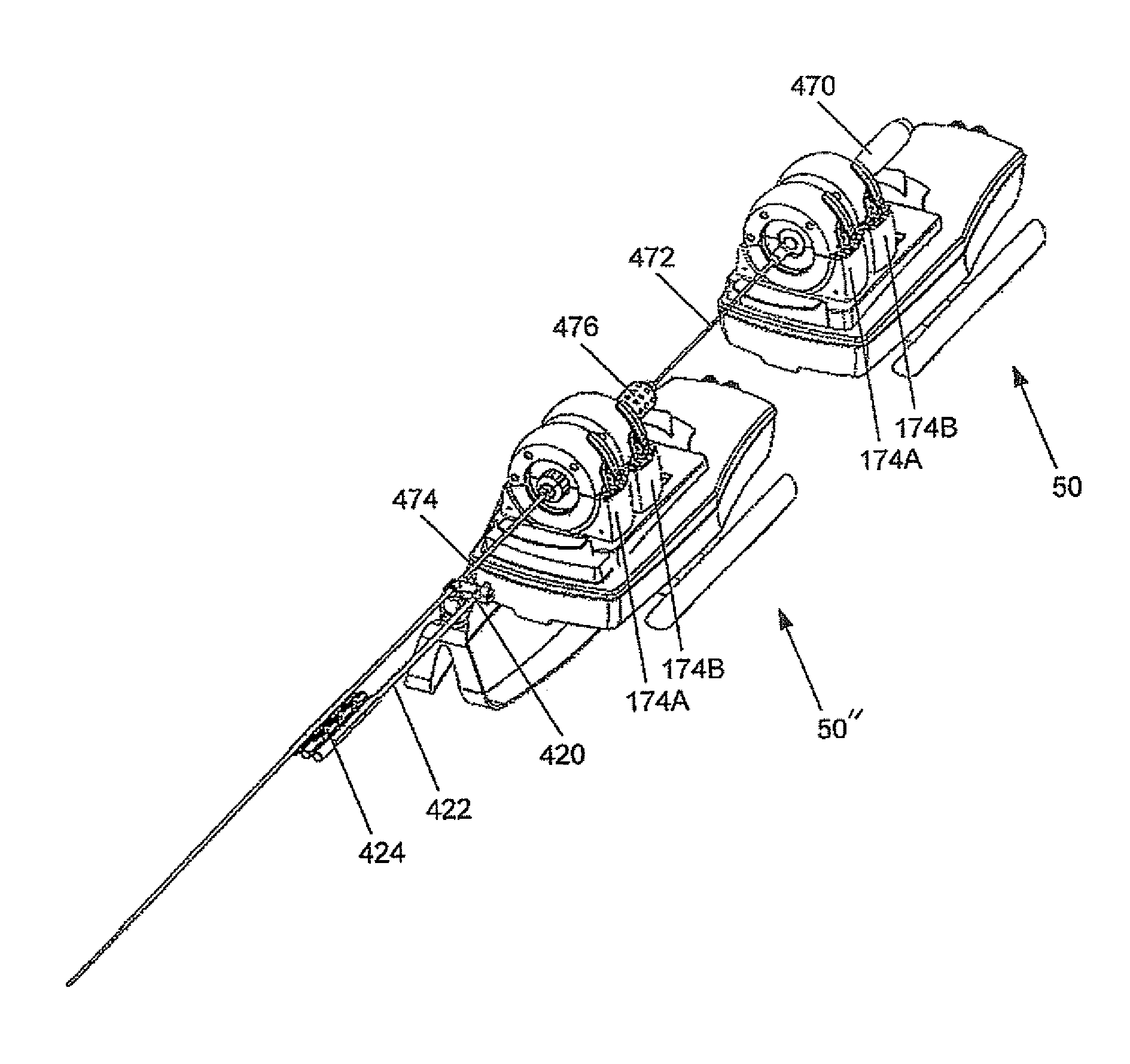
Another alternate arrangement of the remote manipulator of the preferred embodiment is shown in FIGS. 46 and 47 as it would arranged for rotating, operating and advancing a manipulable sheath and for operating and advancing and retracting a medical device in the lumen of the sheath. The remote manipulator 50 engages the handle 470 on the proximal end of a remotely manipulable medical device 472. The remote manipulator 50 can advance retract the medical device, and operate the controls on the handle 470 to cause the distal end of the medical device 472 to bend or other otherwise operate. For example, in the case of a lasso catheter, operating of the controls can deflect the lasso, and expand and contract the loop of the lasso. The distal end of the elongate medical device extends through the lumen of a sheath 474.
The remote manipulator 50'' engages the handle 476 of the remotely manipulable sheath 474. The remote manipulator 50 can rotate, advance and retract the sheath 474 and operate the controls on the handle 476 to cause the distal end of the sheath to bend or turn. Thus the remote operators 50 and 50'' can be operated in coordinated manner so one remote operator 50'' brings the distal end of the sheath 474 to the desired location or orientation, and the remote manipulator 50 advances and retracts the medical device 472 through the lumen of the sheath and out the distal end, and operates the handle 470 to operate the distal end of the medical device. Thus the manipulable sheath 474 can be rotated, advanced and retracted, and operated, and a medical device 472 can be advanced and retracted through the lumen of the manipulable sheath, remotely.
Operation
The operation of the preferred embodiment will be described with respect to a loop type EP Catheter, although, the invention is not so limited and embodiments of the remote manipulator can be used to operate a wide variety of medical devices which can be controlled through the manipulation of handle. The medical device has a handle with an actuator ring. Rotation of the actuator ring relative to the remainder of the handle causes the distal end of the loop catheter to bend. Translation of the actuator ring relative to the remainder of the handle causes the ring at the distal end to increase or decrease in size.
The system is first installed on a patient bed. As shown in FIG. 37, the platform 66 is laid across the surface of the bed, and secured to rails found on the sides of a typical patient bed. The cleats on the 112 and 114 on the base plate 100 are secured to the rail on one side of the bed by tightening the bolts 120 and 122. Similarly, on the opposite side of the bed, the cleat 124 on L-shaped bracket 110 is secured to the rail by tightening the bolt 128. Once the platform 66 has been secured on the patient bed, the bracket 60 is mounted on the platform 66. As shown in FIG. 38, the pins 94 and 96 on the bracket 60 fit into the semi-circular notches 130 and 132 in the support plate 100, and the pin 134 on the plate 100 engages the semi-circular notch 98 in the bracket 60. The bracket 60 and the support plate are secured by tightening bolt 136 on the bracket to engage the slot 138 in the base plate.
The device driver 52 is then positioned in the appropriate location by pivoting the articulating arm 56 around post 58, and securing it with bolt 76. The sections 70 and 72 can be moved and driver device 52 can be pivoted about the first, second, and third axes to bring the driver device to an appropriate position for conducting the procedure.
A surgical drape (not shown) in the form of an elongate plastic bag can be installed over the device driver 52 and articulating arm 56. The drape preferably has a puncturable window that generally corresponds in size and shape to the platform 204, and is aligned therewith. A replaceable disposable device interface 54, which can be provided in a sterile package, is removed from its sterile packaging and installed on the platform 204 of the device driver 52, with the pins 226 and 228 and spline 230 of each of the clamps 174 piercing the drape to connect to the sockets in the driver device. Alternatively, the window in the drape can be a framed opening, the tray 220 can seal with the frame, and the pins 226 and 228, and the spline 230 can engage their respective sockets without interference from the drape.
The elongate medical device is then prepared for use and mounting in the remote manipulator system. As shown in FIG. 39, the distal end of the medical device is introduced into the opening 300 in the proximal end of a telescoping catheter support 302. The telescoping catheter support 302 comprises at least two relatively telescoping tubes 304 and 306 with a lock 308 for locking the tubes 304 and 306 in position to set the length of the support. The distal end of the support 302 engages the introducer sheath. A clip 310 allows the proximal end of the catheter support 302 to engage the mount 168, the spherical shape of the mount 168 helps form a ball joint with the clip 310 to accommodate some motion and realignment.
As shown in FIGS. 40A through 40C, the clamps 174A and 174B are opened, and the handle of the medical device placed in the clamps, with the actuator ring of the medical device aligned with clamp 174A, and the remainder of the handle aligned with clamp 1748. The covers 264 of the clamps 174A and 174B are closed, and the latches 270 engaged.
Once the medical device is engaged in the remote manipulator system, the distal end of the medical device can be introduced into the body and manipulated with the remote manipulation system 50.
When it is desired to advance the catheter, the drive 148 is actuated which causes the translation mechanism 212 to advance the body 170 of the device driver 52 relative to the base 160, which advances the catheter mounted thereon. When it is desired to retract the catheter, the drive 148 is actuated which causes the translation mechanism 212 to retract the body 170 of the device driver relative to its base 160. When it is desired to rotate the distal end of the catheter, the drives 142 and 146 are operated to operate transmissions 206 and 310 which cause the splines 230 of both of the clamps 174A and 174B to turn, thereby turning the split adapter ring gears 302 and thus, the entire device engaged therein. When it is desired to operate the actuation ring on the handle of the device, relative translation of the ring and the remainder of the handle can be caused by operating the drive 144 to operate the translation mechanism 208 to cause the clamp 174B engaging the handle to move relative to the clamp 174A engaging the actuator ring, to thereby cause relative movement between the actuator ring and the handle. Relative rotation of the actuator ring and the remainder of the handle can be caused by operating the drive 142 to operate transmission 206 to operate the spline 230 of clamp 174A, rotating the actuator ring relative to the remainder of the handle, or operating drive 210 to operate transmission 210 to operate the spline 230 of clamp 174B rotating the remainder of the handle relative to the actuator ring, or to operate drives 142 and 146 and different rates and or in different directions to cause relative rotation between the actuator ring engaged in clamp 174A and the remainder of the handle engaged in 174B.
The drives 142, 144, 146, and 148 can be under direct control by a physician through a suitable interface, or the drives can be under the control of a microprocessor under the supervision and direction of a physician.
In an emergency, the clamps 174A and 174B can be easily opened by operating latches 270 to release the cover and pulling the medical device free. The split adapter rings can be easily removed from the device so that the device can be used manually.
Embodiments of the remote manipulator device can be adapted to a wide variety of medical devices to allow the devices to be positioned and operated inside the body under remote control by a physician, or by physician-supervised computer control.
The foregoing description of the embodiments has been provided for purposes of illustration and description. It is not intended to be exhaustive or to limit the invention. Individual elements or features of a particular embodiment are generally not limited to that particular embodiment, but, where applicable, are interchangeable and can be used in a selected embodiment, even if not specifically shown or described. The same may also be varied in many ways. Such variations are not to be regarded as a departure from the invention, and all such modifications are intended to be included within the scope of the invention.
* * * * *
D00000
D00001
D00002
D00003
D00004
D00005
D00006
D00007
D00008
D00009
D00010
D00011
D00012

D00013

D00014

D00015

D00016
D00017

D00018
D00019

D00020

D00021

D00022
D00023

D00024

D00025

D00026

D00027
D00028

D00029

XML
uspto.report is an independent third-party trademark research tool that is not affiliated, endorsed, or sponsored by the United States Patent and Trademark Office (USPTO) or any other governmental organization. The information provided by uspto.report is based on publicly available data at the time of writing and is intended for informational purposes only.
While we strive to provide accurate and up-to-date information, we do not guarantee the accuracy, completeness, reliability, or suitability of the information displayed on this site. The use of this site is at your own risk. Any reliance you place on such information is therefore strictly at your own risk.
All official trademark data, including owner information, should be verified by visiting the official USPTO website at www.uspto.gov. This site is not intended to replace professional legal advice and should not be used as a substitute for consulting with a legal professional who is knowledgeable about trademark law.