Prosthetic heart valve
Iamberger , et al. Ja
U.S. patent number 10,537,426 [Application Number 15/668,559] was granted by the patent office on 2020-01-21 for prosthetic heart valve. This patent grant is currently assigned to CARDIOVALVE LTD.. The grantee listed for this patent is CARDIOVALVE LTD.. Invention is credited to Aviram Baum, Boaz Harari, Ilia Hariton, Meni Iamberger.


View All Diagrams
| United States Patent | 10,537,426 |
| Iamberger , et al. | January 21, 2020 |
Prosthetic heart valve
Abstract
A tubular valve body has an upstream end and a downstream end, and has a central longitudinal axis, and defines a lumen along the axis. Prosthetic leaflets are disposed within the lumen, and are configured to facilitate one-way movement of fluid through the lumen in an upstream-to-downstream direction. The valve body has a cellular structure defined by a plurality of joists connected at nodes, the joists and nodes delimiting cells of the cellular structure. The nodes include minor nodes at which 2-4 joists are connected, and major nodes at which 6-8 joists are connected. The cells of the cellular structure comprise a first circumferential row of first-row cells. Each of the first-row cells is connected to each of its circumferentially-adjacent first-row cells at a respective one of the major nodes, and is longitudinally delimited by two of the minor nodes. Other embodiments are described.
| Inventors: | Iamberger; Meni (Kfar Saba, IL), Baum; Aviram (Tel Aviv, IL), Harari; Boaz (Ganey Tikva, IL), Hariton; Ilia (Zichron Yaackov, IL) | ||||||||||
|---|---|---|---|---|---|---|---|---|---|---|---|
| Applicant: |
|
||||||||||
| Assignee: | CARDIOVALVE LTD. (Or Yehuda,
IL) |
||||||||||
| Family ID: | 65231947 | ||||||||||
| Appl. No.: | 15/668,559 | ||||||||||
| Filed: | August 3, 2017 |
Prior Publication Data
| Document Identifier | Publication Date | |
|---|---|---|
| US 20190038404 A1 | Feb 7, 2019 | |
| Current U.S. Class: | 1/1 |
| Current CPC Class: | A61F 2/2418 (20130101); A61F 2/2436 (20130101); A61F 2/86 (20130101); A61F 2/24 (20130101); A61F 2/2412 (20130101); A61F 2240/001 (20130101); A61F 2230/0063 (20130101); A61F 2/01 (20130101); A61F 2240/004 (20130101) |
| Current International Class: | A61F 2/24 (20060101); A61F 2/86 (20130101); A61F 2/01 (20060101) |
References Cited [Referenced By]
U.S. Patent Documents
| 4261342 | April 1981 | Aranguren |
| 4275469 | June 1981 | Gabbay |
| 4423525 | January 1984 | Vallana et al. |
| 4853986 | August 1989 | Allen |
| 4892541 | January 1990 | Alonso |
| 4994077 | February 1991 | Dobben |
| 5078739 | January 1992 | Martin |
| 5108420 | April 1992 | Marks |
| 5314473 | May 1994 | Godin |
| 5332402 | July 1994 | Teitelbaum |
| 5397351 | March 1995 | Pavcnik et al. |
| 5405378 | April 1995 | Strecker |
| 5443500 | August 1995 | Sigwart |
| 5473812 | December 1995 | Morris et al. |
| 5607444 | March 1997 | Lam |
| 5607470 | March 1997 | Milo |
| 5647857 | July 1997 | Anderson et al. |
| 5702397 | December 1997 | Goble et al. |
| 5765682 | June 1998 | Bley et al. |
| 5868777 | February 1999 | Lam |
| 5873906 | February 1999 | Lau et al. |
| 5954766 | September 1999 | Zadno-Azizi et al. |
| 5980565 | November 1999 | Jayaraman |
| 6010530 | January 2000 | Goicoechea |
| 6019787 | February 2000 | Richard et al. |
| 6042607 | March 2000 | Williamson, IV |
| 6059827 | May 2000 | Fenton |
| 6074417 | June 2000 | Peredo |
| 6113612 | September 2000 | Swanson et al. |
| 6120534 | September 2000 | Ruiz |
| 6152937 | November 2000 | Peterson et al. |
| 6165210 | December 2000 | Lau et al. |
| 6187020 | February 2001 | Zegdi et al. |
| 6193745 | February 2001 | Fogarty et al. |
| 6264700 | July 2001 | Kilcoyne et al. |
| 6287339 | September 2001 | Vasquez et al. |
| 6312465 | November 2001 | Griffin et al. |
| 6332893 | December 2001 | Mortier et al. |
| 6334873 | January 2002 | Lane et al. |
| 6350278 | February 2002 | Lenker et al. |
| 6352561 | March 2002 | Leopold et al. |
| 6391036 | May 2002 | Berg et al. |
| 6402780 | June 2002 | Williamson, IV et al. |
| 6409755 | June 2002 | Vrba |
| 6419696 | July 2002 | Ortiz et al. |
| 6428550 | August 2002 | Vargas et al. |
| 6440164 | August 2002 | Dimatteo et al. |
| 6454799 | September 2002 | Schreck |
| 6458153 | October 2002 | Bailey et al. |
| 6482228 | November 2002 | Norred |
| 6511491 | January 2003 | Grudem et al. |
| 6530952 | March 2003 | Vesely |
| 6540782 | April 2003 | Snyders |
| 6551350 | April 2003 | Thornton et al. |
| 6558396 | May 2003 | Inoue |
| 6558418 | May 2003 | Carpentier et al. |
| 6569196 | May 2003 | Vesely |
| 6602263 | August 2003 | Swanson et al. |
| 6616675 | September 2003 | Evard et al. |
| 6652556 | November 2003 | VanTessel et al. |
| 6669724 | December 2003 | Park et al. |
| 6682558 | January 2004 | Tu et al. |
| 6699256 | March 2004 | Logan et al. |
| 6716244 | April 2004 | Klaco |
| 6719781 | April 2004 | Kim |
| 6719788 | April 2004 | Cox |
| 6730118 | May 2004 | Spenser et al. |
| 6733525 | May 2004 | Yang et al. |
| 6764518 | July 2004 | Godin |
| 6767362 | July 2004 | Schreck |
| 6797002 | September 2004 | Spence et al. |
| 6821297 | November 2004 | Snyders |
| 6830585 | December 2004 | Artof et al. |
| 6830638 | December 2004 | Boylan et al. |
| 6893460 | May 2005 | Spenser et al. |
| 6951571 | October 2005 | Srivastava |
| 6960217 | November 2005 | Bolduc |
| 6964684 | November 2005 | Ortiz et al. |
| 6974476 | December 2005 | McGuckin et al. |
| 7011681 | March 2006 | Vesely |
| 7018406 | March 2006 | Seguin et al. |
| 7041132 | May 2006 | Quijano et al. |
| 7077861 | July 2006 | Spence |
| 7101395 | September 2006 | Tremulis et al. |
| 7101396 | September 2006 | Artof et al. |
| 7137184 | November 2006 | Schreck |
| 7172625 | February 2007 | Shu et al. |
| 7175656 | February 2007 | Khairkhahan |
| 7198646 | April 2007 | Figulla et al. |
| 7201772 | April 2007 | Schwammenthal |
| 7226477 | June 2007 | Cox |
| 7288111 | October 2007 | Holloway et al. |
| 7316716 | January 2008 | Egan |
| 7329279 | February 2008 | Haug et al. |
| 7335213 | February 2008 | Hyde et al. |
| 7351256 | April 2008 | Hojeibane et al. |
| 7374573 | May 2008 | Gabbay |
| 7377938 | May 2008 | Sarac et al. |
| 7381218 | June 2008 | Schreck |
| 7381219 | June 2008 | Salahieh et al. |
| 7404824 | July 2008 | Webler et al. |
| 7422603 | September 2008 | Lane |
| 7429269 | September 2008 | Schwammenthal |
| 7442204 | October 2008 | Schwammenthal |
| 7445630 | November 2008 | Lashinski et al. |
| 7455677 | November 2008 | Vargas et al. |
| 7455688 | November 2008 | Furst et al. |
| 7462162 | December 2008 | Phan et al. |
| 7481838 | January 2009 | Carpentier et al. |
| 7510575 | March 2009 | Spenser et al. |
| 7513909 | April 2009 | Lane et al. |
| 7524331 | April 2009 | Birdsall |
| 7527646 | May 2009 | Rahdert et al. |
| 7556646 | July 2009 | Yang et al. |
| 7582111 | September 2009 | Krolik et al. |
| 7585321 | September 2009 | Cribier |
| 7597711 | October 2009 | Drews et al. |
| 7611534 | November 2009 | Kapadia et al. |
| 7621948 | November 2009 | Hermann et al. |
| 7625403 | December 2009 | Krivoruchko |
| 7632302 | December 2009 | Vreeman et al. |
| 7648528 | January 2010 | Styrc |
| 7682380 | March 2010 | Thornton et al. |
| 7708775 | May 2010 | Rowe et al. |
| 7717952 | May 2010 | Case et al. |
| 7717955 | May 2010 | Lane et al. |
| 7731741 | June 2010 | Eidenschink |
| 7748389 | July 2010 | Salahieh et al. |
| 7753922 | July 2010 | Starksen |
| 7758595 | July 2010 | Allen et al. |
| 7758632 | July 2010 | Hojeibane et al. |
| 7758640 | July 2010 | Vesely |
| 7771467 | August 2010 | Svensson |
| 7771469 | August 2010 | Liddicoat |
| 7776083 | August 2010 | Vesely |
| 7780726 | August 2010 | Seguin |
| 7785341 | August 2010 | Forster et al. |
| 7799069 | September 2010 | Bailey et al. |
| 7803181 | September 2010 | Furst et al. |
| 7811316 | October 2010 | Kalmann et al. |
| 7824442 | November 2010 | Salahieh et al. |
| 7837645 | November 2010 | Bessler et al. |
| 7837727 | November 2010 | Goetz et al. |
| 7842081 | November 2010 | Yadin |
| 7850725 | December 2010 | Vardi et al. |
| 7871432 | January 2011 | Bergin |
| 7871436 | January 2011 | Ryan et al. |
| 7887583 | February 2011 | Macoviak |
| 7892281 | February 2011 | Seguin et al. |
| 7896915 | March 2011 | Guyenot et al. |
| 7914544 | March 2011 | Nguyen et al. |
| 7914569 | March 2011 | Nguyen et al. |
| 7927370 | April 2011 | Webler et al. |
| 7942927 | May 2011 | Kaye et al. |
| 7947072 | May 2011 | Yang et al. |
| 7947075 | May 2011 | Goetz et al. |
| 7955375 | June 2011 | Agnew |
| 7955377 | June 2011 | Melsheimer |
| 7955384 | June 2011 | Rafiee et al. |
| 7959666 | June 2011 | Salahieh et al. |
| 7959672 | June 2011 | Salahieh et al. |
| 7967833 | June 2011 | Sterman et al. |
| 7967857 | June 2011 | Lane |
| 7981151 | July 2011 | Rowe |
| 7981153 | July 2011 | Fogarty et al. |
| 7992567 | August 2011 | Hirotsuka et al. |
| 7993393 | August 2011 | Carpentier et al. |
| 8002825 | August 2011 | Letac et al. |
| 8002826 | August 2011 | Seguin |
| 8016877 | September 2011 | Seguin et al. |
| 8016882 | September 2011 | Macoviak |
| 8021420 | September 2011 | Dolan |
| 8021421 | September 2011 | Fogarty et al. |
| 8025695 | September 2011 | Fogarty et al. |
| 8029518 | October 2011 | Goldfarb et al. |
| 8029557 | October 2011 | Sobrino-Serrano et al. |
| 8029564 | October 2011 | Johnson et al. |
| 8034104 | October 2011 | Carpentier et al. |
| 8038720 | October 2011 | Wallace et al. |
| 8043360 | October 2011 | McNamara et al. |
| 8048138 | November 2011 | Sulivan et al. |
| 8048140 | November 2011 | Purdy |
| 8048153 | November 2011 | Salahieh et al. |
| 8052741 | November 2011 | Bruszewski et al. |
| 8052749 | November 2011 | Salahieh et al. |
| 8057493 | November 2011 | Goldfarb et al. |
| 8057532 | November 2011 | Hoffman |
| 8057540 | November 2011 | Letac et al. |
| 8062355 | November 2011 | Figulla et al. |
| 8062359 | November 2011 | Marquez et al. |
| 8070708 | December 2011 | Rottenberg et al. |
| 8070800 | December 2011 | Lock et al. |
| 8070802 | December 2011 | Lamphere et al. |
| 8070804 | December 2011 | Hyde |
| 8075611 | December 2011 | Milwee et al. |
| 8080054 | December 2011 | Rowe |
| 8083793 | December 2011 | Lane et al. |
| D652927 | January 2012 | Braido et al. |
| D653341 | January 2012 | Braido et al. |
| 8092518 | January 2012 | Schreck |
| 8092520 | January 2012 | Quadri |
| 8092521 | January 2012 | Figulla et al. |
| 8105377 | January 2012 | Liddicoat |
| 8109996 | February 2012 | Stacchino et al. |
| 8118866 | February 2012 | Herrmann et al. |
| 8133270 | March 2012 | Kheradvar et al. |
| 8136218 | March 2012 | Millwee et al. |
| 8137398 | March 2012 | Tuval et al. |
| 8142492 | March 2012 | Forster et al. |
| 8142494 | March 2012 | Rahdert et al. |
| 8142496 | March 2012 | Berreklouw |
| 8142497 | March 2012 | Friedman |
| 8147504 | April 2012 | Ino et al. |
| 8157852 | April 2012 | Bloom et al. |
| 8157853 | April 2012 | Laske et al. |
| 8157860 | April 2012 | McNamara et al. |
| 8163008 | April 2012 | Wilson et al. |
| 8163014 | April 2012 | Lane et al. |
| D660433 | May 2012 | Braido et al. |
| D660967 | May 2012 | Braido et al. |
| 8167894 | May 2012 | Miles et al. |
| 8167932 | May 2012 | Bourang et al. |
| 8167935 | May 2012 | McGuckin, Jr. et al. |
| 8172896 | May 2012 | McNamara et al. |
| 8172898 | May 2012 | Alferness et al. |
| 8177836 | May 2012 | Lee et al. |
| 8182528 | May 2012 | Salahieh et al. |
| 8211169 | July 2012 | Lane et al. |
| 8216301 | July 2012 | Bonhoeffer et al. |
| 8221492 | July 2012 | Case et al. |
| 8221493 | July 2012 | Boyle et al. |
| 8226710 | July 2012 | Nguyen et al. |
| 8231670 | July 2012 | Salahieh et al. |
| 8236045 | August 2012 | Benichou et al. |
| 8236049 | August 2012 | Rowe et al. |
| 8252042 | August 2012 | McNamara et al. |
| 8252051 | August 2012 | Chau et al. |
| 8252052 | August 2012 | Salahieh et al. |
| 8257390 | September 2012 | Carley et al. |
| 8267988 | September 2012 | Hamer et al. |
| 8277501 | October 2012 | Chalekian et al. |
| 8287591 | October 2012 | Keidar et al. |
| 8298280 | October 2012 | Yadin et al. |
| 8303653 | November 2012 | Bonhoeffer et al. |
| 8308798 | November 2012 | Pintor et al. |
| 8317853 | November 2012 | Agnew |
| 8317855 | November 2012 | Gregorich et al. |
| 8323335 | December 2012 | Rowe et al. |
| 8328868 | December 2012 | Paul et al. |
| 8337541 | December 2012 | Quadri et al. |
| 8343174 | January 2013 | Goldfarb et al. |
| 8343213 | January 2013 | Salahieh et al. |
| 8348999 | January 2013 | Kheradvar et al. |
| 8366767 | February 2013 | Zhang |
| 8372140 | February 2013 | Hoffman et al. |
| 8377119 | February 2013 | Drews et al. |
| 8398708 | March 2013 | Meiri et al. |
| 8403981 | March 2013 | Forster et al. |
| 8403983 | March 2013 | Quadri et al. |
| 8408214 | April 2013 | Spenser |
| 8414644 | April 2013 | Quadri et al. |
| 8425593 | April 2013 | Braido et al. |
| 8430934 | April 2013 | Das |
| 8444689 | May 2013 | Zhang |
| 8449599 | May 2013 | Chau et al. |
| 8449625 | May 2013 | Campbell et al. |
| 8454686 | June 2013 | Alkhatib |
| 8460365 | June 2013 | Haverkost et al. |
| 8474460 | July 2013 | Barrett et al. |
| 8500821 | August 2013 | Sobrino-Serrano et al. |
| 8512400 | August 2013 | Tran et al. |
| 8539662 | September 2013 | Stacchino et al. |
| 8540767 | September 2013 | Zhang |
| 8545544 | October 2013 | Spenser et al. |
| 8551160 | October 2013 | Figulla et al. |
| 8551161 | October 2013 | Dolan |
| 8562672 | October 2013 | Bonhoeffer et al. |
| 8579964 | November 2013 | Lane et al. |
| 8579965 | November 2013 | Bonhoeffer et al. |
| 8585755 | November 2013 | Chau et al. |
| 8585756 | November 2013 | Bonhoeffer et al. |
| 8591460 | November 2013 | Wilson et al. |
| 8591570 | November 2013 | Revuelta et al. |
| 8623075 | January 2014 | Murray et al. |
| 8623080 | January 2014 | Fogarty et al. |
| 8628569 | January 2014 | Benichou et al. |
| 8628570 | January 2014 | Seguin |
| 8628571 | January 2014 | Hacohen et al. |
| 8652203 | February 2014 | Quadri et al. |
| 8652204 | February 2014 | Quill et al. |
| 8657872 | February 2014 | Seguin |
| 8663322 | March 2014 | Keranen |
| 8673020 | March 2014 | Sobrino-Serrano et al. |
| 8679174 | March 2014 | Ottma et al. |
| 8685086 | April 2014 | Navia et al. |
| 8696742 | April 2014 | Pintor et al. |
| 8728155 | May 2014 | Montorfano et al. |
| 8734507 | May 2014 | Keranen |
| 8747460 | June 2014 | Tuval et al. |
| 8771345 | July 2014 | Tuval et al. |
| 8784472 | July 2014 | Eidenschink |
| 8784479 | July 2014 | Antonsson et al. |
| 8784481 | July 2014 | Alkhatib et al. |
| 8795355 | August 2014 | Alkhatib |
| 8795356 | August 2014 | Quadri et al. |
| 8795357 | August 2014 | Yohanan et al. |
| 8801776 | August 2014 | House et al. |
| 8808366 | August 2014 | Braido et al. |
| 8840663 | September 2014 | Salahieh et al. |
| 8840664 | September 2014 | Karapetian et al. |
| 8845722 | September 2014 | Gabbay |
| 8852261 | October 2014 | White |
| 8852272 | October 2014 | Gross et al. |
| 8870948 | October 2014 | Erzberger et al. |
| 8870949 | October 2014 | Rowe |
| 8870950 | October 2014 | Hacohen |
| 8876800 | November 2014 | Behan |
| 8894702 | November 2014 | Quadri et al. |
| 8900294 | December 2014 | Paniagua et al. |
| 8900295 | December 2014 | Migliazza et al. |
| 8906083 | December 2014 | Obermiller et al. |
| 8911455 | December 2014 | Quadri et al. |
| 8911489 | December 2014 | Ben-Muvhar |
| 8911493 | December 2014 | Rowe et al. |
| 8932343 | January 2015 | Alkhatib et al. |
| 8961595 | February 2015 | Alkhatib |
| 8979922 | March 2015 | Jayasinghe et al. |
| 8986370 | March 2015 | Annest |
| 8986373 | March 2015 | Chau et al. |
| 8986375 | March 2015 | Garde et al. |
| 8992599 | March 2015 | Thubrikar et al. |
| 8992604 | March 2015 | Gross et al. |
| 8992608 | March 2015 | Haug et al. |
| 8998982 | April 2015 | Richter et al. |
| 9005273 | April 2015 | Salahieh et al. |
| 9011527 | April 2015 | Li et al. |
| 9017399 | April 2015 | Gross et al. |
| D730520 | May 2015 | Braido et al. |
| D730521 | May 2015 | Braido et al. |
| 9023100 | May 2015 | Quadri et al. |
| 9034032 | May 2015 | McLean et al. |
| 9034033 | May 2015 | McLean et al. |
| 9039757 | May 2015 | McLean et al. |
| D732666 | June 2015 | Nguyen et al. |
| 9050188 | June 2015 | Schweich et al. |
| 9072603 | July 2015 | Tuval et al. |
| 9084676 | July 2015 | Chau et al. |
| 9095434 | August 2015 | Rowe |
| 9125738 | September 2015 | Figulla et al. |
| 9125740 | September 2015 | Morriss et al. |
| 9132006 | September 2015 | Spenser et al. |
| 9132009 | September 2015 | Hacohen et al. |
| 9138312 | September 2015 | Tuval et al. |
| 9155619 | October 2015 | Liu et al. |
| 9173738 | November 2015 | Murray et al. |
| 9220594 | December 2015 | Braido et al. |
| 9226820 | January 2016 | Braido et al. |
| 9226839 | January 2016 | Kariniemi et al. |
| 9232995 | January 2016 | Kovalsky et al. |
| 9241790 | January 2016 | Lane et al. |
| 9241791 | January 2016 | Braido et al. |
| 9241794 | January 2016 | Braido et al. |
| 9248014 | February 2016 | Lane et al. |
| 9289290 | March 2016 | Alkhatib et al. |
| 9289291 | March 2016 | Gorman et al. |
| 9295550 | March 2016 | Nguyen et al. |
| 9295552 | March 2016 | McLean et al. |
| 9301836 | April 2016 | Buchbinder et al. |
| D755384 | May 2016 | Pesce et al. |
| 9326852 | May 2016 | Spenser |
| 9326876 | May 2016 | Acosta et al. |
| 9345573 | May 2016 | Nyuli et al. |
| 9387078 | July 2016 | Gross et al. |
| 9421098 | August 2016 | Gifford et al. |
| 9427303 | August 2016 | Liddy et al. |
| 9427316 | August 2016 | Schweich, Jr. et al. |
| 9439757 | September 2016 | Wallace et al. |
| 9474638 | October 2016 | Robinson et al. |
| 9480559 | November 2016 | Vidlund et al. |
| 9492273 | November 2016 | Wallace et al. |
| 9498314 | November 2016 | Behan |
| 9498332 | November 2016 | Hacohen et al. |
| 9532870 | January 2017 | Cooper et al. |
| 9554897 | January 2017 | Lane et al. |
| 9554899 | January 2017 | Granada et al. |
| 9561103 | February 2017 | Granada et al. |
| 9566152 | February 2017 | Schweich et al. |
| 9629716 | April 2017 | Seguin |
| 9681952 | June 2017 | Hacohen et al. |
| 9717591 | August 2017 | Chau et al. |
| 9743932 | August 2017 | Amplatz et al. |
| 9763817 | September 2017 | Roeder |
| 10143552 | December 2018 | Wallace et al. |
| 10149761 | December 2018 | Granada et al. |
| 10154906 | December 2018 | Granada et al. |
| 10182908 | January 2019 | Tubishevitz et al. |
| 2001/0002445 | May 2001 | Vesely |
| 2001/0021872 | September 2001 | Bailey et al. |
| 2001/0056295 | December 2001 | Solem |
| 2002/0032481 | March 2002 | Gabbay |
| 2002/0099436 | July 2002 | Thornton et al. |
| 2002/0151970 | October 2002 | Garrison et al. |
| 2002/0177894 | November 2002 | Acosta et al. |
| 2003/0036791 | February 2003 | Bonhoeffer et al. |
| 2003/0060875 | March 2003 | Wittens |
| 2003/0069635 | April 2003 | Cartledge |
| 2003/0074052 | April 2003 | Besselink |
| 2003/0083742 | May 2003 | Spence et al. |
| 2003/0105519 | June 2003 | Fasol et al. |
| 2003/0158578 | August 2003 | Pantages et al. |
| 2004/0010272 | January 2004 | Manetakis et al. |
| 2004/0039414 | February 2004 | Carley et al. |
| 2004/0093060 | May 2004 | Seguin et al. |
| 2004/0122503 | June 2004 | Campbell et al. |
| 2004/0122514 | June 2004 | Fogarty et al. |
| 2004/0133267 | July 2004 | Lane |
| 2004/0143315 | July 2004 | Bruun et al. |
| 2004/0176839 | September 2004 | Huynh et al. |
| 2004/0186565 | September 2004 | Schreck |
| 2004/0186566 | September 2004 | Hindrichs et al. |
| 2004/0210244 | October 2004 | Vargas et al. |
| 2004/0210304 | October 2004 | Seguin et al. |
| 2004/0220593 | November 2004 | Greenhalgh |
| 2004/0225354 | November 2004 | Allen et al. |
| 2004/0249433 | December 2004 | Freitag |
| 2004/0260389 | December 2004 | Case et al. |
| 2004/0260394 | December 2004 | Douk et al. |
| 2005/0004668 | January 2005 | Aklog et al. |
| 2005/0021056 | January 2005 | St. Goar et al. |
| 2005/0027305 | February 2005 | Shiu et al. |
| 2005/0038494 | February 2005 | Eidenschink |
| 2005/0055086 | March 2005 | Stobie |
| 2005/0075731 | April 2005 | Artof et al. |
| 2005/0080430 | April 2005 | Wright et al. |
| 2005/0137686 | June 2005 | Salahieh et al. |
| 2005/0137688 | June 2005 | Salahieh et al. |
| 2005/0137689 | June 2005 | Salahieh et al. |
| 2005/0137690 | June 2005 | Salahieh et al. |
| 2005/0137695 | June 2005 | Salahieh et al. |
| 2005/0137697 | June 2005 | Salahieh et al. |
| 2005/0143809 | June 2005 | Salahieh et al. |
| 2005/0149160 | July 2005 | McFerran |
| 2005/0154443 | July 2005 | Linder et al. |
| 2005/0182483 | August 2005 | Osborne et al. |
| 2005/0182486 | August 2005 | Gabbay |
| 2005/0197695 | September 2005 | Stacchino et al. |
| 2005/0203549 | September 2005 | Realyvasquez |
| 2005/0216079 | September 2005 | MaCoviak |
| 2005/0234508 | October 2005 | Cummins et al. |
| 2005/0240200 | October 2005 | Bergheim |
| 2005/0251251 | November 2005 | Cribier |
| 2005/0267573 | December 2005 | Macoviak et al. |
| 2006/0004439 | January 2006 | Spenser et al. |
| 2006/0004469 | January 2006 | Sokel |
| 2006/0015171 | January 2006 | Armstrong |
| 2006/0020327 | January 2006 | Lashinski et al. |
| 2006/0020333 | January 2006 | Lashinski et al. |
| 2006/0041189 | February 2006 | Vancaillie |
| 2006/0089627 | April 2006 | Burnett et al. |
| 2006/0111773 | May 2006 | Rittgers et al. |
| 2006/0116750 | June 2006 | Herbert et al. |
| 2006/0135964 | June 2006 | Vesley |
| 2006/0155357 | July 2006 | Melsheimer |
| 2006/0161250 | July 2006 | Shaw |
| 2006/0047297 | August 2006 | Case |
| 2006/0178700 | August 2006 | Quinn |
| 2006/0178740 | August 2006 | Stacchino et al. |
| 2006/0190036 | August 2006 | Wendel et al. |
| 2006/0190038 | August 2006 | Carley et al. |
| 2006/0195183 | August 2006 | Navia et al. |
| 2006/0195184 | August 2006 | Lane et al. |
| 2006/0201519 | September 2006 | Frazier et al. |
| 2006/0212111 | September 2006 | Case et al. |
| 2006/0241656 | October 2006 | Starksen et al. |
| 2006/0241745 | October 2006 | Solem |
| 2006/0241748 | October 2006 | Lee et al. |
| 2006/0247680 | November 2006 | Amplatz et al. |
| 2006/0253191 | November 2006 | Salahieh et al. |
| 2006/0259136 | November 2006 | Nguyen et al. |
| 2006/0259137 | November 2006 | Artof et al. |
| 2006/0271166 | November 2006 | Thill et al. |
| 2006/0271171 | November 2006 | McQuinn et al. |
| 2006/0287719 | December 2006 | Rowe et al. |
| 2007/0016288 | January 2007 | Gurskis et al. |
| 2007/0027528 | February 2007 | Agnew |
| 2007/0027549 | February 2007 | Godin |
| 2007/0038295 | February 2007 | Case et al. |
| 2007/0043435 | February 2007 | Seguin et al. |
| 2007/0055340 | March 2007 | Pryor |
| 2007/0056346 | March 2007 | Spenser et al. |
| 2007/0078510 | April 2007 | Ryan |
| 2007/0112422 | May 2007 | Dehdashtian |
| 2007/0118151 | May 2007 | Davidson |
| 2007/0162103 | July 2007 | Case et al. |
| 2007/0162107 | July 2007 | Haug et al. |
| 2007/0162111 | July 2007 | Fukamachi et al. |
| 2007/0173932 | July 2007 | Cali et al. |
| 2007/0198077 | August 2007 | Cully et al. |
| 2007/0198097 | August 2007 | Zegdi |
| 2007/0213810 | September 2007 | Newhauser et al. |
| 2007/0213813 | September 2007 | Von Segesser et al. |
| 2007/0225759 | September 2007 | Thommen et al. |
| 2007/0225760 | September 2007 | Moszner et al. |
| 2007/0233186 | October 2007 | Meng |
| 2007/0233237 | October 2007 | Krivoruchko |
| 2007/0239272 | October 2007 | Navia et al. |
| 2007/0255400 | November 2007 | Parravicini et al. |
| 2008/0004688 | January 2008 | Spenser et al. |
| 2008/0004697 | January 2008 | Lichtenstein et al. |
| 2008/0051703 | February 2008 | Thornton et al. |
| 2008/0071361 | March 2008 | Tuval et al. |
| 2008/0071363 | March 2008 | Tuval et al. |
| 2008/0071366 | March 2008 | Tuval et al. |
| 2008/0071369 | March 2008 | Tuval et al. |
| 2008/0077235 | March 2008 | Kirson |
| 2008/0082083 | April 2008 | Forde et al. |
| 2008/0082159 | April 2008 | Tseng et al. |
| 2008/0082166 | April 2008 | Styrc et al. |
| 2008/0086164 | April 2008 | Rowe et al. |
| 2008/0086204 | April 2008 | Rankin |
| 2008/0091261 | April 2008 | Long et al. |
| 2008/0097595 | April 2008 | Gabbay |
| 2008/0132989 | June 2008 | Snow et al. |
| 2008/0140003 | June 2008 | Bei et al. |
| 2008/0147182 | June 2008 | Righini et al. |
| 2008/0161910 | July 2008 | Revuelta et al. |
| 2008/0167705 | July 2008 | Agnew |
| 2008/0167714 | July 2008 | St. Goar et al. |
| 2008/0188929 | August 2008 | Schreck |
| 2008/0195200 | August 2008 | Vidlund et al. |
| 2008/0208332 | August 2008 | Lamphere et al. |
| 2008/0221672 | September 2008 | Lamphere et al. |
| 2008/0234814 | September 2008 | Salahieh et al. |
| 2008/0243245 | October 2008 | Thambar et al. |
| 2008/0255580 | October 2008 | Hoffman et al. |
| 2008/0262609 | October 2008 | Gross et al. |
| 2008/0269879 | October 2008 | Sathe et al. |
| 2008/0281411 | November 2008 | Berreklouw |
| 2008/0294234 | November 2008 | Hartley et al. |
| 2009/0005863 | January 2009 | Goetz et al. |
| 2009/0036966 | February 2009 | O'Connor et al. |
| 2009/0054969 | February 2009 | Salahieh et al. |
| 2009/0088836 | April 2009 | Bishop et al. |
| 2009/0099554 | April 2009 | Forster et al. |
| 2009/0099650 | April 2009 | Bolduc et al. |
| 2009/0112159 | April 2009 | Slattery et al. |
| 2009/0157175 | June 2009 | Benichou |
| 2009/0171363 | July 2009 | Chocron |
| 2009/0177278 | July 2009 | Spence |
| 2009/0210052 | August 2009 | Forster et al. |
| 2009/0222081 | September 2009 | Linder et al. |
| 2009/0240320 | September 2009 | Tuval et al. |
| 2009/0248143 | October 2009 | Laham |
| 2009/0264859 | October 2009 | Mas |
| 2009/0264994 | October 2009 | Saadat |
| 2009/0276040 | November 2009 | Rowe et al. |
| 2009/0281619 | November 2009 | Le et al. |
| 2009/0287304 | November 2009 | Dahlgren et al. |
| 2009/0299449 | December 2009 | Styrc |
| 2009/0306768 | December 2009 | Quardi |
| 2009/0319037 | December 2009 | Rowe et al. |
| 2010/0023117 | January 2010 | Yoganathan et al. |
| 2010/0023120 | January 2010 | Holecek et al. |
| 2010/0036479 | February 2010 | Hill et al. |
| 2010/0049313 | February 2010 | Alon et al. |
| 2010/0069852 | March 2010 | Kelley |
| 2010/0076548 | March 2010 | Konno |
| 2010/0100167 | April 2010 | Bortlein et al. |
| 2010/0114299 | May 2010 | Ben-Muvhar et al. |
| 2010/0131054 | May 2010 | Tuval et al. |
| 2010/0137979 | June 2010 | Tuval et al. |
| 2010/0160958 | June 2010 | Clark |
| 2010/0161036 | June 2010 | Pintor et al. |
| 2010/0161042 | June 2010 | Maisano et al. |
| 2010/0174363 | July 2010 | Castro |
| 2010/0179643 | July 2010 | Shalev |
| 2010/0179648 | July 2010 | Richter et al. |
| 2010/0179649 | July 2010 | Richter et al. |
| 2010/0217382 | August 2010 | Chau et al. |
| 2010/0222810 | September 2010 | DeBeer et al. |
| 2010/0228285 | September 2010 | Miles et al. |
| 2010/0234940 | September 2010 | Dolan |
| 2010/0249908 | September 2010 | Chau et al. |
| 2010/0249917 | September 2010 | Zhang |
| 2010/0256737 | October 2010 | Pollock et al. |
| 2010/0262232 | October 2010 | Annest |
| 2010/0280603 | November 2010 | Maisano et al. |
| 2010/0280606 | November 2010 | Naor |
| 2010/0312333 | December 2010 | Navia et al. |
| 2010/0324595 | December 2010 | Linder et al. |
| 2010/0331971 | December 2010 | Keranen et al. |
| 2011/0004296 | January 2011 | Lutter et al. |
| 2011/0015729 | January 2011 | Jimenez et al. |
| 2011/0015731 | January 2011 | Carpentier et al. |
| 2011/0022165 | January 2011 | Oba et al. |
| 2011/0178597 | January 2011 | Navia et al. |
| 2011/0040374 | February 2011 | Goetz et al. |
| 2011/0040375 | February 2011 | Letac et al. |
| 2011/0046662 | February 2011 | Moszner et al. |
| 2011/0054466 | March 2011 | Rothstein et al. |
| 2011/0054596 | March 2011 | Taylor |
| 2011/0054598 | March 2011 | Johnson |
| 2011/0071626 | March 2011 | Wright et al. |
| 2011/0077730 | March 2011 | Fentster |
| 2011/0082538 | April 2011 | Dahlgren et al. |
| 2011/0087322 | April 2011 | Letac et al. |
| 2011/0093063 | April 2011 | Schreck |
| 2011/0098525 | April 2011 | Kermode et al. |
| 2011/0106247 | May 2011 | Miller et al. |
| 2011/0112625 | May 2011 | Ben-Muvhar et al. |
| 2011/0112632 | May 2011 | Chau et al. |
| 2011/0118830 | May 2011 | Liddicoat et al. |
| 2011/0125257 | May 2011 | Seguin et al. |
| 2011/0125258 | May 2011 | Centola |
| 2011/0137326 | June 2011 | Bachman |
| 2011/0137397 | June 2011 | Chau et al. |
| 2011/0137409 | June 2011 | Yang et al. |
| 2011/0137410 | June 2011 | Hacohen |
| 2011/0144742 | June 2011 | Madrid et al. |
| 2011/0166636 | July 2011 | Rowe |
| 2011/0172784 | July 2011 | Richter |
| 2011/0184510 | July 2011 | Maisano et al. |
| 2011/0190877 | August 2011 | Lane et al. |
| 2011/0190879 | August 2011 | Bobo et al. |
| 2011/0202076 | August 2011 | Richter |
| 2011/0208283 | August 2011 | Rust |
| 2011/0208293 | August 2011 | Tabor |
| 2011/0208298 | August 2011 | Tuval et al. |
| 2011/0213459 | September 2011 | Garrison et al. |
| 2011/0213461 | September 2011 | Seguin et al. |
| 2011/0218619 | September 2011 | Benichou et al. |
| 2011/0218620 | September 2011 | Meiri et al. |
| 2011/0224785 | September 2011 | Hacohen |
| 2011/0238159 | September 2011 | Guyenot et al. |
| 2011/0245911 | October 2011 | Quill et al. |
| 2011/0245917 | October 2011 | Savage et al. |
| 2011/0251675 | October 2011 | Dwork |
| 2011/0251676 | October 2011 | Sweeney et al. |
| 2011/0251678 | October 2011 | Eidenschink et al. |
| 2011/0251679 | October 2011 | Wiemeyer et al. |
| 2011/0251680 | October 2011 | Tran et al. |
| 2011/0251682 | October 2011 | Murray, III et al. |
| 2011/0251683 | October 2011 | Tabor |
| 2011/0257721 | October 2011 | Tabor |
| 2011/0257729 | October 2011 | Spenser et al. |
| 2011/0257736 | October 2011 | Marquez et al. |
| 2011/0257737 | October 2011 | Fogarty et al. |
| 2011/0264191 | October 2011 | Rothstein |
| 2011/0264196 | October 2011 | Savage et al. |
| 2011/0264198 | October 2011 | Murray, III et al. |
| 2011/0264199 | October 2011 | Tran et al. |
| 2011/0264200 | October 2011 | Tran et al. |
| 2011/0264201 | October 2011 | Yeung |
| 2011/0264202 | October 2011 | Murray, III et al. |
| 2011/0264203 | October 2011 | Dwork et al. |
| 2011/0264206 | October 2011 | Tabor |
| 2011/0264208 | October 2011 | Duffy |
| 2011/0270276 | November 2011 | Rothstein et al. |
| 2011/0271967 | November 2011 | Mortier et al. |
| 2011/0282438 | November 2011 | Drews et al. |
| 2011/0282439 | November 2011 | Thill et al. |
| 2011/0282440 | November 2011 | Cao |
| 2011/0283514 | November 2011 | Fogarty et al. |
| 2011/0288632 | November 2011 | White |
| 2011/0288634 | November 2011 | Tuval et al. |
| 2011/0295354 | December 2011 | Bueche et al. |
| 2011/0295363 | December 2011 | Girard et al. |
| 2011/0301688 | December 2011 | Dolan |
| 2011/0301698 | December 2011 | Miller et al. |
| 2011/0301701 | December 2011 | Padala et al. |
| 2011/0301702 | December 2011 | Rust et al. |
| 2011/0313452 | December 2011 | Carley et al. |
| 2011/0313515 | December 2011 | Quadri et al. |
| 2011/0319989 | December 2011 | Lane et al. |
| 2011/0319991 | December 2011 | Hariton et al. |
| 2012/0010694 | January 2012 | Lutter et al. |
| 2012/0022633 | January 2012 | Olson et al. |
| 2012/0022637 | January 2012 | Ben-Movhar et al. |
| 2012/0022639 | January 2012 | Hacohen et al. |
| 2012/0022640 | January 2012 | Gross et al. |
| 2012/0035703 | February 2012 | Lutter et al. |
| 2012/0035713 | February 2012 | Lutter et al. |
| 2012/0035722 | February 2012 | Tuval et al. |
| 2012/0041547 | February 2012 | Duffy et al. |
| 2012/0041551 | February 2012 | Spenser et al. |
| 2012/0046738 | February 2012 | Lau et al. |
| 2012/0046742 | February 2012 | Tuval et al. |
| 2012/0053676 | March 2012 | Ku et al. |
| 2012/0053682 | March 2012 | Kovalsky et al. |
| 2012/0053688 | March 2012 | Fogarty et al. |
| 2012/0059454 | March 2012 | Millwee et al. |
| 2012/0065464 | March 2012 | Ellis et al. |
| 2012/0078237 | March 2012 | Wang et al. |
| 2012/0078353 | March 2012 | Quadri et al. |
| 2012/0078357 | March 2012 | Conklin |
| 2012/0083832 | April 2012 | Delaloye et al. |
| 2012/0083839 | April 2012 | Letac et al. |
| 2012/0083879 | April 2012 | Eberhardt et al. |
| 2012/0089223 | April 2012 | Nguyen et al. |
| 2012/0101570 | April 2012 | Tuval et al. |
| 2012/0101571 | April 2012 | Thambar et al. |
| 2012/0101572 | April 2012 | Kovalsky et al. |
| 2012/0123511 | May 2012 | Brown |
| 2012/0123530 | May 2012 | Carpentier et al. |
| 2012/0130473 | May 2012 | Norris et al. |
| 2012/0130474 | May 2012 | Buckley |
| 2012/0130475 | May 2012 | Shaw |
| 2012/0136434 | May 2012 | Carpentier et al. |
| 2012/0150218 | June 2012 | Sandgren et al. |
| 2012/0165915 | June 2012 | Melsheimer et al. |
| 2012/0179244 | July 2012 | Schankereli et al. |
| 2012/0197292 | August 2012 | Chin-Chen et al. |
| 2012/0283824 | November 2012 | Lutter et al. |
| 2012/0290062 | November 2012 | McNamara et al. |
| 2012/0296360 | November 2012 | Norris et al. |
| 2012/0300063 | November 2012 | Majkrzak et al. |
| 2012/0310328 | December 2012 | Olson et al. |
| 2012/0323316 | December 2012 | Chau et al. |
| 2012/0330408 | December 2012 | Hillukka et al. |
| 2013/0006347 | January 2013 | McHugo |
| 2013/0018450 | January 2013 | Hunt |
| 2013/0018458 | January 2013 | Yohanan et al. |
| 2013/0035759 | February 2013 | Gross et al. |
| 2013/0041204 | February 2013 | Heilman et al. |
| 2013/0041451 | February 2013 | Patterson et al. |
| 2013/0046373 | February 2013 | Cartledge et al. |
| 2013/0079872 | March 2013 | Gallagher |
| 2013/0116780 | May 2013 | Miller et al. |
| 2013/0123896 | May 2013 | Bloss et al. |
| 2013/0123900 | May 2013 | Eblacas et al. |
| 2013/0150945 | June 2013 | Crawford et al. |
| 2013/0150956 | June 2013 | Yohanan et al. |
| 2013/0158647 | June 2013 | Norris et al. |
| 2013/0166017 | June 2013 | Cartledge et al. |
| 2013/0166022 | June 2013 | Conklin |
| 2013/0172978 | July 2013 | Vidlund et al. |
| 2013/0172992 | July 2013 | Gross et al. |
| 2013/0190861 | July 2013 | Chau et al. |
| 2013/0211501 | August 2013 | Buckley et al. |
| 2013/0245742 | September 2013 | Norris |
| 2013/0261737 | October 2013 | Costello |
| 2013/0261738 | October 2013 | Clague et al. |
| 2013/0289711 | October 2013 | Liddy et al. |
| 2013/0297013 | November 2013 | Klima et al. |
| 2013/0304197 | November 2013 | Buchbinder et al. |
| 2013/0304200 | November 2013 | McLean et al. |
| 2013/0310928 | November 2013 | Morriss et al. |
| 2013/0325114 | December 2013 | McLean et al. |
| 2013/0331929 | December 2013 | Mitra et al. |
| 2014/0005778 | January 2014 | Buchbinder et al. |
| 2014/0018911 | January 2014 | Zhou et al. |
| 2014/0031928 | January 2014 | Murphy et al. |
| 2014/0046430 | February 2014 | Shaw |
| 2014/0052237 | February 2014 | Lane et al. |
| 2014/0067054 | March 2014 | Chau et al. |
| 2014/0081376 | March 2014 | Burkart et al. |
| 2014/0106951 | April 2014 | Brandon |
| 2014/0120287 | May 2014 | Jacoby et al. |
| 2014/0121749 | May 2014 | Roeder |
| 2014/0121763 | May 2014 | Duffy et al. |
| 2014/0135894 | May 2014 | Norris et al. |
| 2014/0135895 | May 2014 | Andress et al. |
| 2014/0142681 | May 2014 | Norris |
| 2014/0148891 | May 2014 | Johnson |
| 2014/0163690 | June 2014 | White |
| 2014/0172069 | June 2014 | Roeder et al. |
| 2014/0172082 | June 2014 | Bruchman et al. |
| 2014/0188210 | July 2014 | Beard et al. |
| 2014/0188221 | July 2014 | Chung et al. |
| 2014/0194981 | July 2014 | Menk et al. |
| 2014/0194983 | July 2014 | Kovalsky et al. |
| 2014/0207231 | July 2014 | Hacohen et al. |
| 2014/0214159 | July 2014 | Vidlund et al. |
| 2014/0222136 | August 2014 | Geist et al. |
| 2014/0249622 | September 2014 | Carmi et al. |
| 2014/0257461 | September 2014 | Robinson et al. |
| 2014/0257467 | September 2014 | Lane et al. |
| 2014/0257475 | September 2014 | Gross et al. |
| 2014/0257476 | September 2014 | Montorfano et al. |
| 2014/0277358 | September 2014 | Slazas |
| 2014/0277418 | September 2014 | Miller |
| 2014/0277422 | September 2014 | Ratz et al. |
| 2014/0277427 | September 2014 | Ratz et al. |
| 2014/0296962 | October 2014 | Cartledge et al. |
| 2014/0296969 | October 2014 | Tegels et al. |
| 2014/0324164 | October 2014 | Gross et al. |
| 2014/0336744 | November 2014 | Tani et al. |
| 2014/0343670 | November 2014 | Bakis et al. |
| 2014/0358224 | December 2014 | Tegels et al. |
| 2014/0379065 | December 2014 | Johnson et al. |
| 2014/0379074 | December 2014 | Spence et al. |
| 2014/0379076 | December 2014 | Vidlund et al. |
| 2015/0018944 | January 2015 | O'Connor et al. |
| 2015/0045880 | February 2015 | Hacohen |
| 2015/0045881 | February 2015 | Lim |
| 2015/0094802 | April 2015 | Buchbinder et al. |
| 2015/0119970 | April 2015 | Nakayama et al. |
| 2015/0127097 | May 2015 | Neumann et al. |
| 2015/0142103 | May 2015 | Vidlund |
| 2015/0157457 | June 2015 | Hacohen |
| 2015/0173896 | June 2015 | Richter et al. |
| 2015/0173897 | June 2015 | Raanani et al. |
| 2015/0216661 | August 2015 | Hacohen et al. |
| 2015/0238313 | August 2015 | Spence et al. |
| 2015/0245934 | September 2015 | Lombardi et al. |
| 2015/0272730 | October 2015 | Melnick et al. |
| 2015/0282964 | October 2015 | Beard et al. |
| 2015/0320556 | November 2015 | Levi et al. |
| 2015/0327994 | November 2015 | Morriss et al. |
| 2015/0328000 | November 2015 | Ratz et al. |
| 2015/0335429 | November 2015 | Morriss et al. |
| 2015/0342736 | December 2015 | Rabito et al. |
| 2015/0351904 | December 2015 | Cooper et al. |
| 2015/0351906 | December 2015 | Hammer et al. |
| 2015/0359629 | December 2015 | Ganesan et al. |
| 2016/0030169 | February 2016 | Shahriari |
| 2016/0030171 | February 2016 | Quijano et al. |
| 2016/0095700 | April 2016 | Righini |
| 2016/0106539 | April 2016 | Buchbinder et al. |
| 2016/0113766 | April 2016 | Ganesan et al. |
| 2016/0113768 | April 2016 | Ganesan et al. |
| 2016/0125160 | May 2016 | Heneghan et al. |
| 2016/0213473 | July 2016 | Hacohen et al. |
| 2016/0220367 | August 2016 | Barrett |
| 2016/0228247 | August 2016 | Maimon et al. |
| 2016/0242902 | August 2016 | Morriss et al. |
| 2016/0270911 | September 2016 | Ganesan et al. |
| 2016/0296330 | October 2016 | Hacohen |
| 2016/0310268 | October 2016 | Oba et al. |
| 2016/0310274 | October 2016 | Gross et al. |
| 2016/0317301 | November 2016 | Quadri et al. |
| 2016/0324633 | November 2016 | Gross et al. |
| 2016/0324640 | November 2016 | Gifford et al. |
| 2016/0331526 | November 2016 | Schweich et al. |
| 2016/0331527 | November 2016 | Vidlund et al. |
| 2016/0367360 | December 2016 | Cartledge et al. |
| 2016/0367368 | December 2016 | Vidlund et al. |
| 2016/0374801 | December 2016 | Jimenez et al. |
| 2017/0042678 | February 2017 | Ganesan et al. |
| 2017/0056166 | March 2017 | Ratz et al. |
| 2017/0056171 | March 2017 | Cooper et al. |
| 2017/0065407 | March 2017 | Hacohen et al. |
| 2017/0128205 | May 2017 | Tamir et al. |
| 2017/0196688 | July 2017 | Christianson et al. |
| 2017/0196692 | July 2017 | Kirk et al. |
| 2017/0209264 | July 2017 | Chau et al. |
| 2017/0216026 | August 2017 | Quill et al. |
| 2017/0231759 | August 2017 | Geist et al. |
| 2017/0231760 | August 2017 | Lane et al. |
| 2018/0049873 | February 2018 | Manash et al. |
| 2018/0055628 | March 2018 | Patel et al. |
| 2018/0055630 | March 2018 | Patel et al. |
| 2018/0153689 | June 2018 | Maimon et al. |
| 2018/0177594 | June 2018 | Patel et al. |
| 2018/0296341 | October 2018 | Noe et al. |
| 0170262 | Feb 1986 | EP | |||
| 1264582 | Dec 2002 | EP | |||
| 1768630 | Jan 2015 | EP | |||
| 1998/043557 | Oct 1998 | WO | |||
| 1999/030647 | Jun 1999 | WO | |||
| 2000-047139 | Aug 2000 | WO | |||
| 2001-062189 | Aug 2001 | WO | |||
| 03/028558 | Apr 2003 | WO | |||
| 2004/108191 | Dec 2004 | WO | |||
| 2005/107650 | Nov 2005 | WO | |||
| 2006/007401 | Jan 2006 | WO | |||
| 06/054930 | May 2006 | WO | |||
| 2006/070372 | Jul 2006 | WO | |||
| 2006/089236 | Aug 2006 | WO | |||
| 2007/059252 | May 2007 | WO | |||
| 08/013915 | Jan 2008 | WO | |||
| 2008/029296 | Mar 2008 | WO | |||
| 2008/070797 | Jun 2008 | WO | |||
| 2008/103722 | Aug 2008 | WO | |||
| 09/033469 | Mar 2009 | WO | |||
| 09/053497 | Apr 2009 | WO | |||
| 2009/091509 | Jul 2009 | WO | |||
| 2010/006627 | Jan 2010 | WO | |||
| 2010/037141 | Apr 2010 | WO | |||
| 2010/057262 | May 2010 | WO | |||
| 2010/073246 | Jul 2010 | WO | |||
| 2010/081033 | Jul 2010 | WO | |||
| 2010/121076 | Oct 2010 | WO | |||
| 2011/025972 | Mar 2011 | WO | |||
| 2011/069048 | Jun 2011 | WO | |||
| 2011/089601 | Jul 2011 | WO | |||
| 2011/106137 | Sep 2011 | WO | |||
| 2011/111047 | Sep 2011 | WO | |||
| 01/87190 | Nov 2011 | WO | |||
| 2011/137531 | Nov 2011 | WO | |||
| 2011-143263 | Nov 2011 | WO | |||
| 2011/154942 | Dec 2011 | WO | |||
| 2012/011108 | Jan 2012 | WO | |||
| 2012/024428 | Feb 2012 | WO | |||
| 2012/036740 | Mar 2012 | WO | |||
| 2012/048035 | Apr 2012 | WO | |||
| 2012/127309 | Sep 2012 | WO | |||
| 2012/177942 | Dec 2012 | WO | |||
| 2013/021374 | Feb 2013 | WO | |||
| 2013/021375 | Feb 2013 | WO | |||
| 2013/021384 | Feb 2013 | WO | |||
| 2013/059747 | Apr 2013 | WO | |||
| 2013/078497 | Jun 2013 | WO | |||
| 2013/128436 | Sep 2013 | WO | |||
| 2014/022124 | Feb 2014 | WO | |||
| 2014/076696 | May 2014 | WO | |||
| 2014/115149 | Jul 2014 | WO | |||
| 2014/145338 | Sep 2014 | WO | |||
| 2014/164364 | Oct 2014 | WO | |||
| 2014/194178 | Dec 2014 | WO | |||
| 2015/173794 | Nov 2015 | WO | |||
| 2016/016899 | Feb 2016 | WO | |||
| 2016/093877 | Jun 2016 | WO | |||
| 2016/125160 | Aug 2016 | WO | |||
| 2017/223486 | Dec 2017 | WO | |||
| 2018/025260 | Feb 2018 | WO | |||
| 2018/029680 | Feb 2018 | WO | |||
| 2018/039631 | Mar 2018 | WO | |||
| 2018/106837 | Jun 2018 | WO | |||
| 2018/112429 | Jun 2018 | WO | |||
| 2018/118717 | Jun 2018 | WO | |||
| 2018/131042 | Jul 2018 | WO | |||
| 2018/131043 | Jul 2018 | WO | |||
Other References
|
An Office Action dated Nov. 16, 2018, which issued during the prosecution of U.S. Appl. No. 16/042,028. cited by applicant . An Invitation to pay additional fees dated Oct. 11, 2018, which issued during the prosecution of Applicant's PCT/IL2018/050725. cited by applicant . An Office Action dated Dec. 4, 2018, which issued during the prosecution of U.S. Appl. No. 16/045,059. cited by applicant . An Office Action together with the English translation dated Nov. 5, 2018 which issued during the prosecution of Chinese Patent Application No. 201680008328.5. cited by applicant . Notice of Allowance dated Sep. 25, 2018, which issued during the prosecution of U.S. Appl. No. 15/188,507. cited by applicant . European Search Report dated Sep. 26, 2018 which issued during the prosecution of Applicant's European App No. 18186784.7. cited by applicant . An Office Action dated Nov. 26, 2018, which issued during the prosecution of U.S. Appl. No. 16/040,831. cited by applicant . An Office Action dated Jul. 11, 2018, which issued during the prosecution of U.S. Appl. No. 15/978,494. cited by applicant . An Office Action dated Nov. 23, 2018, which issued during the prosecution of U.S. Appl. No. 16/041,208. cited by applicant . An Office Action dated Jun. 15, 2018, which issued during the prosecution of U.S. Appl. No. 15/970,314. cited by applicant . An Office Action dated Oct. 12, 2018, which issued during the prosecution of U.S. Appl. No. 15/970,314. cited by applicant . An Office Action dated Jul. 26, 2018, which issued during the prosecution of U.S. Appl. No. 15/979,686. cited by applicant . An Office Action dated Sep. 10, 2018, which issued during the prosecution of U.S. Appl. No. 16/008,618. cited by applicant . An Office Action dated Sep. 6, 2018, which issued during the prosecution of U.S. Appl. No. 15/994,022. cited by applicant . An Office Action dated Sep. 7, 2018, which issued during the prosecution of U.S. Appl. No. 15/995,725. cited by applicant . European Search Report dated Jun. 29, 2017, which issued during the prosecution of Applicant's European App No. 11809374.9. cited by applicant . An Invitation to pay additional fees dated Sep. 29, 2017, which issued during the prosecution of Applicant's PCT/IL2017/050873. cited by applicant . An Advisory Action dated Apr. 2, 2018, which issued during the prosecution of U.S. Appl. No. 14/763,004. cited by applicant . An Office Action dated Jul. 26, 2018, which issued during the prosecution of U.S. Appl. No. 15/872,501. cited by applicant . An Office Action dated May 4, 2018, which issued during the prosecution of U.S. Appl. No. 15/872,501. cited by applicant . An Office Action dated Apr. 20, 2018, which issued during the prosecution of U.S. Appl. No. 15/886,517. cited by applicant . An Office Action dated Aug. 9, 2018, which issued during the prosecution of U.S. Appl. No. 15/899,858. cited by applicant . An Office Action dated Aug. 9, 2018, which issued during the prosecution of U.S. Appl. No. 15/902,403. cited by applicant . An Office Action dated Jun. 28, 2018, which issued during the prosecution of Design U.S. Appl. No. 29/635,658. cited by applicant . An Office Action dated Jun. 28, 2018, which issued during the prosecution of Design U.S. Appl. No. 29/635,661. cited by applicant . Notice of Allowance dated Apr. 20, 2018, which issued during the prosecution of U.S. Appl. No. 15/878,206. cited by applicant . An Office Action dated Jun. 18, 2018, which issued during the prosecution of UK Patent Application No. 1800399.6. cited by applicant . An Office Action dated Jun. 6, 2018, which issued during the prosecution of UK Patent Application No. 1720803.4. cited by applicant . An International Search Report and a Written Opinion both dated Jun. 20, 2018, which issued during the prosecution of Applicant's PCT/IL2018/050024. cited by applicant . An International Search Report and a Written Opinion both dated Nov. 9, 2018, which issued during the prosecution of Applicant's PCT/IL2018/050869. cited by applicant . An International Search Report and a Written Opinion both dated May 13, 2019, which issued during the prosecution of Applicant's PCT/IL2018/051350. cited by applicant . An International Search Report and a Written Opinion both dated Apr. 5, 2019, which issued during the prosecution of Applicant's PCT/IL2019/050142. cited by applicant . An International Search Report and a Written Opinion both dated Jan. 25, 2019, which issued during the prosecution of Applicant's PCT/IL2018/051122. cited by applicant . An International Search Report and a Written Opinion both dated Dec. 5, 2018, which issued during the prosecution of Applicant's PCT/IL2018/050725. cited by applicant . An International Preliminary Report on Patentability dated Feb. 12, 2019, which issued during the prosecution of Applicant's PCT/IL2017/050873. cited by applicant . An International Preliminary Report on Patentability dated Feb. 5, 2019, which issued during the prosecution of Applicant's PCT/IL2017/050849. cited by applicant . An Office Action dated Mar. 25, 2019, which issued during the prosecution of European Patent Application No. 14710060.6. cited by applicant . An Office Action dated Oct. 25, 2018, which issued during the prosecution of U.S. Appl. No. 14/763,004. cited by applicant . An Office Action dated Mar. 4, 2019, which issued during the prosecution of U.S. Appl. No. 14/763,004. cited by applicant . An Office Action dated Jan. 9, 2019, which issued during the prosecution of U.S. Appl. No. 15/329,920. cited by applicant . An Office Action dated Jan. 30, 2019, which issued during the prosecution of U.S. Appl. No. 15/872,501. cited by applicant . An Office Action dated Feb. 5, 2019, which issued during the prosecution of U.S. Appl. No. 15/899,858. cited by applicant . An Office Action dated May 23, 2019, which issued during the prosecution of U.S. Appl. No. 15/668,659. cited by applicant . An Office Action dated May 1, 2019, which issued during the prosecution of U.S. Appl. No. 15/691,032. cited by applicant . An Office Action dated Oct. 23, 2017, which issued during the prosecution of U.S. Appl. No. 14/763,004. cited by applicant . An Office Action dated Jan. 17, 2018, which issued during the prosecution of U.S. Appl. No. 14/763,004. cited by applicant . An Office Action dated Dec. 7, 2017, which issued during the prosecution of U.S. Appl. No. 15/213,791. cited by applicant . An Office Action dated Feb. 8, 2018, which issued during the prosecution of U.S. Appl. No. 15/213,791. cited by applicant . An Office Action dated Feb. 2, 2018, which issued during the prosecution of U.S. Appl. No. 15/329,920. cited by applicant . An Office Action dated Feb. 7, 2018, which issued during the prosecution of U.S. Appl. No. 15/197,069. cited by applicant . An Office Action dated Jan. 5, 2018, which issued during the prosecution of U.S. Appl. No. 15/541,783. cited by applicant . An Invitation to pay additional fees dated Jan. 2, 2018, which issued during the prosecution of Applicant's PCT/IL2017/050849. cited by applicant . An Office Action dated Nov. 23, 2012, which issued during the prosecution of U.S. Appl. No. 13/033,852. cited by applicant . An Office Action dated Dec. 31, 2012, which issued during the prosecution of U.S. Appl. No. 13/044,694. cited by applicant . An Office Action dated Feb. 6, 2013, which issued during the prosecution of U.S. Appl. No. 13/412,814. cited by applicant . Langer F et al., "RING plus STRING: Papillary muscle repositioning as an adjunctive repair technique for ischemic mitral regurgitation," J Thorac Cardiovasc Surg 133:247-9, Jan. 2007. cited by applicant . Langer F et al., "RING+STRING: Successful repair technique for ischemic mitral regurgitation with severe leaflet tethering," Circulation 120[suppl 1]: S85-S91, Sep. 2009. cited by applicant . "Transcatheter Valve-in-Valve Implantation for Failed Bioprosthetic Heart Valves", J Webb et al., Circulation. Apr. 2010; 121: 1848-1857. cited by applicant . Jansen, J., Willeke, S., Reul, H. and Rum, G. (1992), Detachable Shape-Memory Sewing Ring for Heart Valves. Artificial Organs, 16:294-297. 1992 (an abstract). cited by applicant . Alexander S. Geha, et al., Replacement of degenerated mitral and aortic bioprostheses without explanation Ann Thorac Surg. Jun. 2001; 72:1509-1514. cited by applicant . An International Search Report and a Written Opinion both dated Oct. 13, 2011 which issued during the prosecution of Applicant's PCT/IL11/00231. cited by applicant . An Office Action dated Jul. 1, 2016, which issued during the prosecution of U.S. Appl. No. 14/161,921. cited by applicant . An International Search Report and a Written Opinion both dated Dec. 5, 2011, which issued during the prosecution of Applicant's PCT/IL11/00582. cited by applicant . An Office Action dated May 29, 2012, which issued during the prosecution of U.S. Appl. No. 12/840,463. cited by applicant . U.S. Appl. No. 61/555,160, filed Nov. 3, 2011. cited by applicant . U.S. Appl. No. 61/525,281, filed Aug. 19, 2011. cited by applicant . U.S. Appl. No. 61/537,276, filed Sep. 21, 2011. cited by applicant . U.S. Appl. No. 61/515,372, filed Aug. 5, 2011. cited by applicant . U.S. Appl. No. 61/492,449, filed Jun. 2, 2011. cited by applicant . U.S. Appl. No. 61/588,892, filed Jan. 20, 2012. cited by applicant . An International Search Report and a Written Opinion both dated Feb. 6, 2013, which issued during the prosecution of Applicant's PCT/IL12/00292. cited by applicant . An International Search Report and a Written Opinion both dated Feb. 6, 2013, which issued during the prosecution of Applicant's PCT/IL12/00293. cited by applicant . An Office Action dated Nov. 28, 2012, which issued during the prosecution of U.S. Appl. No. 12/961,721. cited by applicant . An Office Action dated Feb. 15, 2013, which issued during the prosecution of U.S. Appl. No. 12/840,463. cited by applicant . An Office Action dated Feb. 10, 2014, which issued during the prosecution of U.S. Appl. No. 13/033,852. cited by applicant . An Office Action dated Sep. 19, 2014, which issued during the prosecution of U.S. Appl. No. 13/044,694. cited by applicant . An International Search Report and a Written Opinion both dated Sep. 4, 2014 which issued during the prosecution of Applicant's PCT/IL2014/050087. cited by applicant . Invitation to Pay Additional Fees dated Jun. 12, 2014 PCT/IL2014/050087. cited by applicant . An Office Action dated Jun. 17, 2014, which issued during the prosecution of U.S. Appl. No. 12/961,721. cited by applicant . An Office Action dated Jul. 3, 2014, which issued during the prosecution of U.S. Appl. No. 13/033,852. cited by applicant . An Office Action dated May 23, 2014, which issued during the prosecution of U.S. Appl. No. 13/412,814. cited by applicant . Dominique Himbert; Mitral Regurgitation and Stenosis from Bioprosthesis and Annuloplasty Failure: Transcatheter approaches and outcomes, 24 pages Oct. 28, 2013. cited by applicant . An International Search Report and a Written Opinion both dated Mar. 17, 2014 which issued during the prosecution of Applicant's PCT/IL2013/050937. cited by applicant . An International Preliminary Report on patentabilty dated Dec. 2, 2013, which issued during the prosecution of Applicant's PCT/IL11/00582. cited by applicant . An Office Action dated Sep. 12, 2013, which issued during the prosecution of U.S. Appl. No. 13/412,814. cited by applicant . An Office Action dated Aug. 2, 2013, which issued during the prosecution of U.S. Appl. No. 13/033,852. cited by applicant . An International Preliminary Report on patentabilty dated Sep. 11, 2012, which issued during the prosecution of Applicant's PCT/IL2011/000231. cited by applicant . An Office Action dated Jul. 2, 2014, which issued during the prosecution of U.S. Appl. No. 13/811,308. cited by applicant . An Office Action dated Jan. 20, 2016, which issued during the prosecution of U.S. Appl. No. 14/161,921. cited by applicant . An Office Action dated Jul. 23, 2013, which issued during the prosecution of U.S. Appl. No. 12/961,721. cited by applicant . An Office Action dated Jul. 18, 2013, which issued during the prosecution of U.S. Appl. No. 13/044,694. cited by applicant . An Office Action dated Nov. 8, 2013, which issued during the prosecution of U.S. Appl. No. 12/840,463. cited by applicant . An Office Action dated Jun. 4, 2014, which issued during the prosecution of U.S. Appl. No. 12/840,463. cited by applicant . An Office Action dated Aug. 13, 2012, which issued during the prosecution of U.S. Appl. No. 13/044,694. cited by applicant . An Office Action dated Jul. 2, 2012, which issued during the prosecution of U.S. Appl. No. 13/033,852. cited by applicant . An Office Action dated Feb. 3, 2014, which issued during the prosecution of U.S. Appl. No. 13/811,308. cited by applicant . An International Preliminary Report on patentabilty dated Feb. 11, 2014, which issued during the prosecution of Applicant's PCT/IL12/00292. cited by applicant . An International Preliminary Report on patentabilty dated Feb. 11, 2014, which issued during the prosecution of Applicant's PCT/IL12/00293. cited by applicant . A Notice of Allowance dated Aug. 15, 2014, which issued during the prosecution of U.S. Appl. No. 13/412,814. cited by applicant . An Office Action dated Aug. 14, 2012, which issued during the prosecution of U.S. Appl. No. 12/961,721. cited by applicant . U.S. Appl. No. 61/283,819, filed Dec. 8, 2009. cited by applicant . Notice of Allowance dated Sep. 29, 2016, which issued during the prosecution of U.S. Appl. No. 14/442,541. cited by applicant . U.S. Appl. No. 61/756,034, filed Jan. 24, 2013. cited by applicant . U.S. Appl. No. 61/756,049, filed Jan. 24, 2013. cited by applicant . Notice of Allowance dated Jul. 1, 2016, which issued during the prosecution of U.S. Appl. No. 14/442,541. cited by applicant . An Office Action dated Mar. 25, 2015, which issued during the prosecution of U.S. Appl. No. 12/840,463. cited by applicant . Notice of Allowance dated May 5, 2015, which issued during the prosecution of U.S. Appl. No. 12/840,463. cited by applicant . Georg Lutter, MD, et al; "Percutaneous Valve Replacement: Current State and Future Prospects", The Annals of Thoracic Surgery ; vol. 78, pp. 2199-2206; Dec. 2004. cited by applicant . An Office Action dated Dec. 10, 2015, which issued during the prosecution of U.S. Appl. No. 14/237,258. cited by applicant . An International Preliminary Report on Patentability dated Jul. 28, 2015, which issued during the prosecution of Applicant's PCT/IL2014/050087. cited by applicant . An Office Action dated Nov. 27, 2015, which issued during the prosecution of U.S. Appl. No. 14/626,267. cited by applicant . An Office Action dated Jan. 21, 2016, which issued during the prosecution of U.S. Appl. No. 14/237,264. cited by applicant . An Office Action dated Apr. 13, 2016, which issued during the prosecution of U.S. Appl. No. 14/626,267. cited by applicant . An International Search Report and a Written Opinion both dated May 30, 2016, which issued during the prosecution of Applicant's PCT/IL2016/050125. cited by applicant . An Office Action dated Sep. 26, 2016, which issued during the prosecution of U.S. Appl. No. 14/763,004. cited by applicant . An Office Action dated Jan. 18, 2017, which issued during the prosecution of U.S. Appl. No. 14/626,267. cited by applicant . An Office Action dated Feb. 7, 2017, which issued during the prosecution of U.S. Appl. No. 14/689,608. cited by applicant . An Office Action dated Feb. 8, 2017, which issued during the prosecution of UK Patent Application No. 1613219.3. cited by applicant . An Office Action together dated Feb. 10, 2017, which issued during the prosecution of European Patent Application No. 12821522.5. cited by applicant . An International Search Report and a Written Opinion both dated Oct. 27, 2015, which issued during the prosecution of Applicant's PCT/IL2015/050792. cited by applicant . European Search Report dated Feb. 18, 2015, which issued during the prosecution of Applicant's European App No. 12821522.5. cited by applicant . Saturn Project--a novel solution for transcatheter heart valve replacement specifically designed to address clinical therapeutic needs on mitral valve: Dec. 2016. cited by applicant . Righini presentation EuroPCR May 2015 (Saturn)--(downloaded from: https://www.pcronline.com/Cases-resourcesimages/Resources/Course-videos-s- lides/2015/Cardiovascularinnovation-pipeline-Mitral-and-tricuspid-valve-in- terventions). cited by applicant . An International Preliminary Report on Patentability dated Jan. 31, 2017, which issued during the prosecution of Applicant's PCT/IL2015/050792. cited by applicant . An Office Action dated Jan. 30, 2015, which issued during the prosecution of UK Patent Application No. 1413474.6. cited by applicant . An International Preliminary Report on Patentability dated May 19, 2015, which issued during the prosecution of Applicant's PCT/IL2013/050937. cited by applicant . Dusan Pavcnik, MD, PhD2, et al; "Development and Initial Experimental Evaluation of a Prosthetic Aortic Valve for Transcatheter Placement", Cardiovascular Radiology. Radiology Apr. 1992, vol. 183, pp. 151-154. cited by applicant . Notice of Allowance dated Oct. 16, 2013, which issued during the prosecution of U.S. Appl. No. 13/675,119. cited by applicant . Notice of Allowance dated Feb. 11, 2015, which issued during the prosecution of U.S. Appl. No. 13/033,852. cited by applicant . Notice of Allowance dated Mar. 10, 2015, which issued during the prosecution of U.S. Appl. No. 13/811,308. cited by applicant . An Office Action dated Aug. 28, 2015, which issued during the prosecution of U.S. Appl. No. 14/237,264. cited by applicant . Notice of Allowance dated Apr. 8, 2016, which issued during the prosecution of U.S. Appl. No. 14/237,258. cited by applicant . Notice of Allowance dated May 10, 2016, which issued during the prosecution of U.S. Appl. No. 14/237,258. cited by applicant . Notice of Allowance dated May 20, 2016, which issued during the prosecution of U.S. Appl. No. 14/237,258. cited by applicant . An Office Action dated Jun. 30, 2015, which issued during the prosecution of U.S. Appl. No. 14/522,987. cited by applicant . An Office Action dated Feb. 25, 2016, which issued during the prosecution of U.S. Appl. No. 14/522,987. cited by applicant . Notice of Allowance dated Dec. 13, 2013, which issued during the prosecution of U.S. Appl. No. 13/675,119. cited by applicant . An International Preliminary Report on Patentability dated Aug. 8, 2017, which issued during the prosecution of Applicant's PCT/IL2016/050125. cited by applicant . Maisano (2015) TCR presentation re Cardiovalve. cited by applicant . U.S. Appl. No. 62/112,343, filed Feb. 5, 2015. cited by applicant. |
Primary Examiner: Baria; Dinah
Attorney, Agent or Firm: Cuenot, Forsythe & Kim, LLC Kim; Stanley A.
Claims
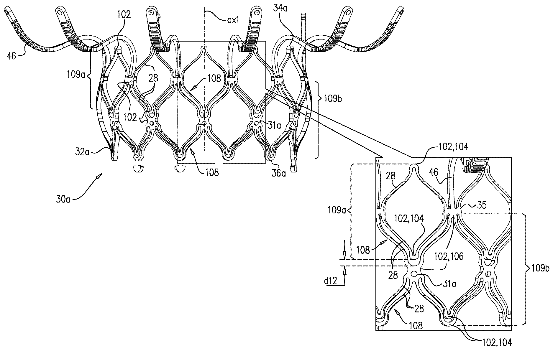
The invention claimed is:
1. Apparatus, comprising: a valve body that: is tubular, has an upstream end, a downstream end, and a central longitudinal axis, and defines a lumen along the central longitudinal axis; and a plurality of prosthetic leaflets, disposed within the lumen, and configured to facilitate one-way movement of fluid through the lumen in an upstream-to-downstream direction, wherein: the valve body has a cellular structure defined by a plurality of joists connected at a plurality of nodes, the joists and nodes delimiting cells of the cellular structure, the plurality of nodes including minor nodes at which 2-4 joists are connected, and major nodes at which 6-8 joists are connected, the cells of the cellular structure comprise a first circumferential row of first-row cells, each of the first-row cells (i) being connected to each of its circumferentially-adjacent first-row cells at a respective one of the major nodes, and (ii) being longitudinally delimited by two of the minor nodes, the cellular structure further comprises a second circumferential row of second-row cells, each of the second-row cells (i) being connected to each of its circumferentially-adjacent second-row cells at a respective one of the major nodes, and (ii) being longitudinally delimited by at least one of the major nodes, and each of the first-row cells and each of the second-row cells is delimited by exactly four nodes.
2. The apparatus according to claim 1, wherein at the minor nodes exactly two joists are connected.
3. The apparatus according to claim 1, wherein at the major nodes exactly six joists are connected.
4. The apparatus according to claim 1, wherein, for each of the first-row cells, the first-row cell is not connected to another cell at the two minor nodes that longitudinally delimit the first-row cell.
5. The apparatus according to claim 1, wherein the apparatus comprises a frame assembly that comprises (i) an inner frame that defines the valve body, and (ii) an outer frame that circumscribes the valve body, and is coupled to the inner frame by being fixed to a plurality of the major nodes of the valve body.
6. The apparatus according to claim 1, wherein each of the second-row cells is also longitudinally delimited by one of the minor nodes.
7. The apparatus according to claim 1, wherein each of the respective major nodes at which the circumferentially-adjacent first-row cells are connected is also a major node that longitudinally-delimits a second-row cell.
8. The apparatus according to claim 1, wherein all the cells of the cellular structure of the valve body are either first-row cells or second-row cells.
9. The apparatus according to claim 1, wherein the apparatus comprises a frame assembly that comprises (i) an inner frame that defines the valve body, and (ii) an outer frame that circumscribes the valve body, and is coupled to the inner frame by being fixed to the major nodes at which the circumferentially-adjacent second-row cells are connected.
10. The apparatus according to claim 1, wherein the first and second circumferential rows are disposed at opposing ends of the valve body.
11. The apparatus according to claim 10, wherein the first circumferential row is disposed at the upstream end of the valve body, and the second circumferential row is disposed at the downstream end of the valve body.
12. Apparatus, comprising: a valve body that: is tubular, has an upstream end, a downstream end, and a central longitudinal axis, and defines a lumen along the central longitudinal axis; and a plurality of prosthetic leaflets, disposed within the lumen, and configured to facilitate one-way movement of fluid through the lumen in an upstream-to-downstream direction, wherein: the tubular valve body has a cellular structure defined by a plurality of joists connected at a plurality of nodes, the joists and nodes delimiting cells of the cellular structure, the plurality of nodes including minor nodes at which 2-4 joists are connected, and major nodes at which 6-8 joists are connected, the cells of the cellular structure comprise a first circumferential row of first-row cells, each of the first-row cells (i) being connected to each of its circumferentially-adjacent first-row cells at a respective one of the major nodes, and (ii) being longitudinally delimited by two of the minor nodes, the cellular structure further comprises a second circumferential row of second-row cells, each of the second-row cells (i) being connected to each of its circumferentially-adjacent second-row cells at a respective one of the major nodes, and (ii) being longitudinally delimited by at least one of the major nodes, and the second circumferential row is rotationally offset with respect to the first circumferential row, such that the second-row cells are rotationally staggered with respect to the first-row cells.
13. The apparatus according to claim 12, wherein at the minor nodes exactly two joists are connected.
14. The apparatus according to claim 12, wherein at the major nodes exactly six joists are connected.
15. The apparatus according to claim 12, wherein, for each of the first-row cells, the first-row cell is not connected to another cell at the two minor nodes that longitudinally delimit the first-row cell.
16. The apparatus according to claim 12, wherein the apparatus comprises a frame assembly that comprises (i) an inner frame that defines the valve body, and (ii) an outer frame that circumscribes the valve body, and is coupled to the inner frame by being fixed to a plurality of the major nodes of the valve body.
17. The apparatus according to claim 12, wherein each of the second-row cells is also longitudinally delimited by one of the minor nodes.
18. The apparatus according to claim 12, wherein each of the respective major nodes at which the circumferentially-adjacent first-row cells are connected is also a major node that longitudinally-delimits a second-row cell.
19. The apparatus according to claim 12, wherein all the cells of the cellular structure of the valve body are either first-row cells or second-row cells.
20. The apparatus according to claim 12, wherein the apparatus comprises a frame assembly that comprises (i) an inner frame that defines the valve body, and (ii) an outer frame that circumscribes the valve body, and is coupled to the inner frame by being fixed to the major nodes at which the circumferentially-adjacent second-row cells are connected.
21. The apparatus according to claim 12, wherein each of the first-row cells and each of the second-row cells is delimited by exactly four nodes.
22. The apparatus according to claim 12, wherein the first and second circumferential rows are disposed at opposing ends of the valve body.
23. The apparatus according to claim 22, wherein the first circumferential row is disposed at the upstream end of the valve body, and the second circumferential row is disposed at the downstream end of the valve body.
Description
FIELD OF THE INVENTION
Some applications of the present invention relate in general to valve replacement. More specifically, some applications of the present invention relate to prosthetic valves for replacement of a cardiac valve.
BACKGROUND
Ischemic heart disease causes regurgitation of a heart valve by the combination of ischemic dysfunction of the papillary muscles, and the dilatation of the ventricle that is present in ischemic heart disease, with the subsequent displacement of the papillary muscles and the dilatation of the valve annulus.
Dilation of the annulus of the valve prevents the valve leaflets from fully coapting when the valve is closed. Regurgitation of blood from the ventricle into the atrium results in increased total stroke volume and decreased cardiac output, and ultimate weakening of the ventricle secondary to a volume overload and a pressure overload of the atrium.
SUMMARY OF THE INVENTION
For some applications, an implant is provided having a tubular portion, an upstream support portion and one or more flanges. The implant is percutaneously deliverable to a native heart valve in a compressed state, and is expandable at the native valve. The implant comprises an inner frame and an outer frame. The upstream support portion is at least partly defined by the inner frame, and the flanges are defined by the outer frame. The implant is secured at the native valve by sandwiching tissue of the native valve between the upstream support portion and the flanges.
There is therefore provided, in accordance with an application of the present invention, apparatus, including:
a tubular valve body having an upstream end and a downstream end, and having a central longitudinal axis, and defining a lumen along the axis; and
a plurality of prosthetic leaflets, disposed within the lumen, and configured to facilitate one-way movement of fluid through the lumen in an upstream-to-downstream direction:
the valve body has a cellular structure defined by a plurality of joists connected at a plurality of nodes, the joists and nodes delimiting cells of the cellular structure, the plurality of nodes including minor nodes at which 2-4 joists are connected, and major nodes at which 6-8 joists are connected, and
the cells of the cellular structure include a first circumferential row of first-row cells, each of the first-row cells being connected to each of its circumferentially-adjacent first-row cells at a respective one of the major nodes, and being longitudinally delimited by two of the minor nodes.
In an application, at the minor nodes exactly two joists are connected.
In an application, at the major nodes exactly six joists are connected.
In an application, for each of the first-row cells, the first-row cell is not connected to another cell at the two minor nodes that longitudinally delimit the first-row cell.
In an application, the apparatus includes a frame assembly that includes (i) an inner frame that defines the valve body, and (ii) an outer frame that circumscribes the valve body, and is coupled to the inner frame by being fixed to a plurality of the major nodes of the valve body.
In an application, the cellular structure further includes a second circumferential row of second-row cells, each of the second-row cells being connected to each of its circumferentially-adjacent second-row cells at a respective one of the major nodes, and being longitudinally delimited by at least one of the major nodes.
In an application, each of the second-row cells is also longitudinally delimited by one of the minor nodes.
In an application, each of the respective major nodes at which the circumferentially-adjacent first-row cells are connected is also a major node that longitudinally-delimits a second-row cell.
In an application, all the cells of the cellular structure of the valve body are either first-row cells or second-row cells.
In an application, the apparatus includes a frame assembly that includes (i) an inner frame that defines the valve body, and (ii) an outer frame that circumscribes the valve body, and is coupled to the inner frame by being fixed to the major nodes at which the circumferentially-adjacent second-row cells are connected.
In an application, each of the first-row cells and each of the second-row cells is delimited by exactly four nodes.
In an application, the first and second circumferential rows are disposed at opposing ends of the valve body.
In an application, the first circumferential row is disposed at the upstream end of the valve body, and the second circumferential row is disposed at the downstream end of the valve body.
There is further provided, in accordance with an application of the present invention, apparatus, including:
a tubular valve body having an upstream end and a downstream end, and having a central longitudinal axis, and defining a lumen along the axis; and
a plurality of prosthetic leaflets, disposed within the lumen, and configured to facilitate one-way movement of fluid through the lumen in an upstream-to-downstream direction:
the valve body has a cellular structure defined by a plurality of joists connected at a plurality of nodes, the joists and nodes delimiting cells of the cellular structure, the plurality of nodes including: minor nodes at which 2-4 joists are connected, and which are arranged in minor-node rows, each minor-node row circumscribing the longitudinal axis at a respective minor-node-row longitudinal site, and major nodes at which 6-8 joists are connected, and which are arranged in major-node rows, each major-node row circumscribing the longitudinal axis at a respective major-node-row longitudinal site, and
along at least part of the longitudinal axis, the minor-node-row longitudinal sites alternate with the major-node-row longitudinal sites.
In an application, at the minor nodes exactly two joists are connected.
In an application, at the major nodes exactly six joists are connected.
There is further provided, in accordance with an application of the present invention, apparatus, including a prosthetic valve, the prosthetic valve including:
a frame assembly, including: an inner frame, defining a tubular valve body having an upstream end and a downstream end, and having a central longitudinal axis, and defining a lumen along the axis; and an outer frame that circumscribes the valve body; and
a plurality of prosthetic leaflets, disposed within the lumen, and configured to facilitate one-way movement of fluid through the lumen in an upstream-to-downstream direction:
the valve body has a cellular structure defined by a plurality of joists connected at a plurality of nodes, the joists and nodes delimiting cells of the cellular structure, the plurality of nodes including minor nodes at which 2-4 joists are connected, and major nodes at which 6-8 joists are connected, and
the outer frame is coupled to the inner frame by being fixed to major nodes of the valve body.
In an application, at the minor nodes exactly two joists are connected.
In an application, at the major nodes exactly six joists are connected.
There is further provided, in accordance with an application of the present invention, apparatus, including:
an implant frame, having an upstream end and a downstream end, and having a central longitudinal axis, and defining a lumen along the axis and: the implant frame has a cellular structure defined by a plurality of joists connected at a plurality of nodes arranged in node rows, each node row circumscribing the longitudinal axis at a respective longitudinal site, the joists and nodes delimiting cells of the cellular structure, the plurality of nodes including: minor nodes at which 2-4 joists are connected, and which are arranged in node rows that are minor-node rows, and major nodes at which 6-8 joists are connected, and which are arranged in node rows that are major-node rows, and a most upstream node row and a most downstream node row are minor-node rows.
In an application, at least two major-node rows are disposed longitudinally between the most upstream node row and the most downstream node row.
In an application, at least two minor-node rows are disposed between the most upstream node row and the most downstream node row.
In an application, the node rows are arranged along the longitudinal axis in the following order:
a first minor-node row, which is the most upstream node row,
a first major-node row,
a second minor-node row,
a second major-node row,
a third minor-node row, and
a fourth minor-node row, which is the most downstream mode row.
There is further provided, in accordance with an application of the present invention, apparatus, including:
a tubular valve body having an upstream end and a downstream end, having a central longitudinal axis, defining a lumen along the axis, and including a plurality of connected joists; and
a plurality of prosthetic leaflets, disposed within the lumen, and configured to facilitate one-way movement of fluid through the lumen in an upstream-to-downstream direction:
the valve body has a cellular structure defined by the joists delimiting cells, the cellular structure including a first circumferential row of cells, and a second circumferential row of cells that are tessellated with the cells of the first row, and
the joists that delimit the cells of the first row do not delimit cells of the second row.
There is further provided, in accordance with an application of the present invention, apparatus for use with a native heart valve of a subject, the apparatus including a prosthetic valve, the prosthetic valve including:
a valve body, shaped to define a lumen therethrough, the lumen defining a longitudinal axis of the prosthetic valve;
an upstream support portion, including: a plurality of arms, coupled to and extending radially outward from the valve body; and an annular sheet disposed over and supported by the arms;
and
a plurality of elongate projections extending from the valve body in an upstream direction through the annular sheet; and
a valve member, disposed within the lumen of the valve body.
In an application, the prosthetic valve includes a nub at the end of each projection.
In an application, the prosthetic valve includes the same number of arms as elongate projections.
In an application, the elongate projections curve inwards toward the longitudinal axis.
In an application:
the prosthetic valve includes a valve frame that defines the valve body, has a cellular structure, and has an upstream end that defines alternating peaks and troughs, the peaks being further upstream than the troughs,
the arms are attached to the valve body at the troughs, and
the elongate projections are attached to the valve body at the peaks.
There is further provided, in accordance with an application of the present invention, a method for augmenting, with a soft pad, a tissue-engaging flange of a frame of a prosthetic valve, the tissue-engaging flange being configured to facilitate anchoring of the prosthetic valve, the method including:
affixing, to the flange, a model of the soft pad;
subsequently, forming a mold by: positioning the frame such that the model is supported within a fluid of a first substance while the first substance solidifies, and subsequently, removing the model from the first substance, leaving a cavity in the solidified first substance;
subsequently, removing the model from the flange;
subsequently, forming the pad by: placing the flange in contact with a second substance by repositioning the frame such that the flange is supported within the cavity, and introducing a fluid of the second substance to the cavity, and while the flange remains in contact with the second substance, allowing the second substance to solidify and become affixed to the flange; and
removing, from the cavity, the flange with the formed pad affixed thereto, the formed pad being of the solidified second substance.
In an application, the solidified second substance is a solid silicone material, and the step of allowing the second substance to solidify and become affixed to the flange, includes allowing the second substance to solidify into the solid silicone material and become affixed to the flange.
In an application, the solidified second substance is a foam, and the step of allowing the second substance to solidify and become affixed to the flange, includes allowing the second substance to solidify into the foam and become affixed to the flange.
In an application:
the frame has a plurality of flanges,
the step of affixing the model to the flange includes affixing a respective plurality of models to the plurality of flanges,
the step of forming the mold includes forming a mold that includes a respective plurality of cavities using the respective plurality of models, and
forming the pad includes forming a plurality of pads on the respective plurality of flanges by: placing the plurality of flanges in contact with the second substance by repositioning the frame such that the flanges are supported in respective cavities, and introducing the fluid of the second substance to the cavities, and while the flanges remain in contact with the second substance, allowing the second substance to solidify and become affixed to the flanges.
In an application, the frame is a first frame of the prosthetic valve, and the prosthetic valve includes a second frame, and the method further includes, subsequently to forming the plurality of pads, coupling the first frame to the second frame.
In an application, the second frame has an upstream end, a downstream end, and a longitudinal axis therebetween, and coupling the first frame to the second frame includes coupling the first frame to the second frame such that the pads are arranged circumferentially around the second frame longitudinally between the upstream end and the downstream end, exclusive.
There is further provided, in accordance with an application of the present invention, apparatus for use with a native heart valve of a subject, the apparatus including a prosthetic valve, the prosthetic valve including:
a frame assembly that defines: a valve body, shaped to define a lumen therethrough, the lumen defining a longitudinal axis of the prosthetic valve; a plurality of arms, coupled to the valve body; and
a valve member, disposed within the lumen of the valve body, and:
the prosthetic valve has a compressed state in which the prosthetic valve is transluminally deliverable to the native heart valve, and is expandable at the native heart valve into an expanded state in which the valve member facilitates one-way blood flow through the lumen,
in the expanded state, the plurality of arms extends radially outward from the valve body, and
in the compressed state, the plurality of arms defines a ball at an end of the valve body.
In an application, the frame assembly includes a monolithic valve frame that defines the valve body and the plurality of arms.
In an application:
the frame assembly includes a first frame and a second frame,
the first frame defines the valve body and the plurality of arms,
the second frame circumscribes the first frame and defines a plurality of flanges, and
in the expanded state the plurality of flanges extends radially outward from the valve body and toward the plurality of arms.
In an application, in the compressed state, the frame assembly defines a waist longitudinally between the valve body and the ball.
In an application, at the waist the transverse diameter of the frame assembly is less than 40 percent of the greatest transverse width of the ball.
In an application, at the waist the frame assembly has a transverse diameter that is less than 5 mm.
In an application, a greatest transverse diameter of the ball is 8-12 mm.
There is further provided, in accordance with an application of the present invention, apparatus, including:
a prosthetic valve, including: a frame assembly that defines: a valve body, shaped to define a lumen therethrough, the lumen defining a longitudinal axis of the prosthetic valve; a plurality of arms, coupled to the valve body; and a valve member, disposed within the lumen of the valve body; and
a delivery tube that includes a circumferential wall that defines a cavity,
the apparatus has a delivery state in which:
the prosthetic valve is in a compressed state, and is disposed within the cavity,
the prosthetic valve and the delivery tube define a toroidal gap therebetween, the toroidal gap circumscribing the longitudinal axis of the prosthetic valve,
the valve body extends in a first longitudinal direction away from the toroidal gap, and the arms extend in a second longitudinal direction away from the toroidal gap.
In an application, the valve member defines an upstream direction and a downstream direction of the prosthetic valve, and the first longitudinal direction is the downstream direction and the second longitudinal direction is the upstream direction.
In an application, the frame assembly includes a first frame, and a second frame that circumscribes the first frame, and in the delivery state, the second frame is disposed only downstream of the toroidal gap, but the first frame is disposed both upstream and downstream of the toroidal gap.
In an application, the frame assembly further defines a plurality of flanges that, in the delivery state, extend from a coupling point with the valve body, and toward the toroidal gap, such that the toroidal gap is disposed between the tips of the flanges and the arms.
In an application, the toroidal gap is defined between the tips of the flanges and a downstream side of the arms.
There is further provided, in accordance with an application of the present invention, apparatus for use with a native heart valve of a subject, the apparatus including:
a valve body, having an upstream end and a downstream end, shaped to define a lumen from the upstream end to the downstream end, the lumen defining a longitudinal axis of the prosthetic valve, and the valve body having;
a fabric liner, lining the lumen;
a valve member, disposed within the lumen of the valve body; and
a polytetrafluoroethylene ring coupled to the downstream end of the valve body such that the ring circumscribes the lumen at the downstream end of the valve body.
In an application, the ring is sutured to the downstream end of the valve body by sutures that wrap around the ring but do not pierce the ring.
In an application, the valve body includes an expandable frame that defines the lumen, the fabric liner lining the lumen defined by the expandable frame, and the polytetrafluoroethylene ring covers the valve frame at the downstream end.
The present invention will be more fully understood from the following detailed description of applications thereof, taken together with the drawings, in which:
BRIEF DESCRIPTION OF THE DRAWINGS
FIGS. 1A-D and 2 are schematic illustrations of an implant and a frame assembly of the implant, in accordance with some applications of the invention;
FIGS. 3A-F are schematic illustrations showing the implantation of the implant at a native valve of a heart of a subject, in accordance with some applications of the invention;
FIG. 4 is a schematic illustration of an implant, in accordance with some applications of the invention;
FIGS. 5A-C are schematic illustration of an implant and its inner frame, in accordance with some applications of the invention;
FIG. 6 is a schematic illustration of an outer frame of a frame assembly of an implant, in accordance with some applications of the invention;
FIG. 7 is a schematic illustration of an inner frame of a frame assembly of an implant, in accordance with some applications of the invention; and
FIGS. 8A-H are schematic illustrations of a technique for use with a frame of a prosthetic valve, in accordance with some applications of the invention.
DETAILED DESCRIPTION OF EMBODIMENTS
Reference is made to FIGS. 1A-D and 2, which are schematic illustrations of an implant 20 and a frame assembly 22 of the implant, in accordance with some applications of the invention. Implant 20 serves as a prosthetic valve for use at a native heart valve of a subject--typically the mitral valve. Implant 20 has a compressed state for minimally-invasive (typically transluminal, e.g., transfemoral) delivery, and an expanded state into which the implant is transitioned at the native heart valve, and in which the implant provides prosthetic valve functionality. Implant 20 comprises frame assembly 22, a covering 23, and a valve member, such as prosthetic leaflets 58.
FIGS. 1A-D show implant 20 and frame assembly 22 in the expanded state. For clarity, FIGS. 1A-C show frame assembly 22 alone. FIG. 1A shows an exploded view of frame assembly 22, and FIGS. 16 and 1C are side- and top-views, respectively, of the frame assembly assembled. FIG. 1D is a perspective view of implant 20, including covering 23 and leaflets 58.
Implant 20 has an upstream end 24, a downstream end 26, and defines a central longitudinal axis ax1 therebetween. Frame assembly 22 comprises a valve frame 30 that comprises a valve body (which is a generally tubular portion) 32 that has an upstream end 34 and a downstream end 36, and is shaped to define a lumen 38 through the valve body from its upstream end to its downstream end. Valve body 32 circumscribes axis ax1, and thereby defines lumen 38 along the axis. Valve frame 30 further comprises a plurality of arms 46, each of which, in the expanded state, extends radially outward from valve body 32.
Valve body 32 is defined by a repeating pattern of cells that extends around central longitudinal axis ax1. In the expanded state of each tubular portion, these cells are typically narrower at their upstream and downstream extremities than midway between these extremities. For example, and as shown, the cells may be roughly diamond or astroid in shape. Typically, and as shown, valve body 32 is defined by two stacked, tessellated rows of cells--an upstream row 29a and a downstream row 29b. Frame 30 is typically made by cutting (e.g., laser-cutting) its basic structure from a tube of, for example, Nitinol (followed by re-shaping and heat treating). Although valve body 32 is therefore typically monolithic, because the resulting cellular structure of valve body 32 resembles an open lattice, it may be useful to describe it as defining a plurality of joists 28 that connect at nodes 100 to form the cellular structure.
Typically, and as shown, each arm 46 is attached to and extends from a site 35 that is at the connection between two adjacent cells of upstream row 29a (alternatively described as being at the upstream extremity of cells of downstream row 29b). Site 35 is therefore a node 100 that connects four joists 28. Upstream end 34 of valve body 32 may be described as defining alternating peaks and troughs, and sites 35 are downstream of the peaks (e.g., at the troughs).
It is hypothesized by the inventors that connecting arm 46 to valve body 32 at site 35 (instead of at upstream end 34) maintains the length of the lumen of the tubular portion, but also advantageously reduces the distance that the tubular portion extends into the ventricle of the subject, and thereby reduces a likelihood of inhibiting blood flow out of the ventricle through the left ventricular outflow tract. It is further hypothesized by the inventors that because each site 35 is a node 100 that connects four joists (whereas each node 100 that is at upstream end 34 connects only two joists), sites 35 are more rigid, and therefore connecting arms 46 to valve body 32 at sites 35 provides greater rigidity to upstream support portion 40.
Arms 46 are typically covered with a covering 23, which typically comprises a flexible sheet, such as a fabric, e.g., comprising polyester. Typically, and as shown in FIG. 1D, the covering extends between arms 46 to form an annular sheet 25, e.g., so as to reduce a likelihood of paravalvular leakage. For some such applications, excess covering 23 is provided between arms 46, so as to facilitate movement of arms 46 independently of each other. Covering 23 may cover the upstream and/or downstream side of arms 46.
Alternatively, each arm 46 may be individually covered in a sleeve of covering 23, thereby facilitating independent movement of the arms.
Arms 46, and typically the covering that covers the arms, define an upstream support portion 40 of implant 20.
Other surfaces of frame assembly 22 may also be covered with covering 23. Typically, covering 23 covers at least part of valve body 32, e.g., lining an inner surface of the valve body, and thereby defining lumen 38.
Frame assembly 22 further comprises a plurality of legs 50 that, in the expanded state, protrude radially outward. Each leg 50 defines a tissue-engaging flange 54, which is typically the most radially outward part of the leg (i.e., is the extremity of the leg). Typically, legs 50 are defined by an outer frame (or "leg frame") 60 that circumscribes and is coupled to valve frame 30. Frames 30 and 60 define respective coupling elements 31 and 61, which are fixed with respect to each other at coupling points 52. For some applications, frames 30 and 60 are attached to each other only at coupling points 52. Although frames 30 and 60 are attached to each other at coupling points 52, radial forces may provide further coupling between the frames, e.g., frame 30 pressing radially outward against frame 60.
Typically, coupling points 52 are circumferentially aligned with legs 50 (and flanges 54 thereof), but circumferentially offset with respect to arms 46. That is, the coupling points are typically at the same rotational position around axis ax1 as the legs, but are rotationally staggered with respect to the rotational position of the arms.
Coupling points 52 are typically disposed circumferentially around frame assembly 22 on a transverse plane that is orthogonal to axis ax1. That is, coupling points 52 are typically all disposed at the same longitudinal position along axis ax1. Typically, coupling points 52 are disposed longitudinally between upstream end 24 and downstream end 26 of frame assembly 22, but not at either of these ends. Further typically, coupling points 52 are disposed longitudinally between upstream end 34 and downstream end 36 of tubular portion 32, but not at either of these ends. As shown, tubular portion 32 is typically barrel-shaped--i.e., slightly wider in the middle than at either end. For some applications, and as shown, coupling points 52 are disposed slightly downstream of the widest part of tubular portion 32. For example, coupling points 52 may be 0.5-3 mm downstream of the widest part of tubular portion 32. Alternatively or additionally, the longitudinal distance between the widest part of tubular portion 32 and coupling points 52 may be 20-50 percent (e.g., 20-40 percent) of the longitudinal distance between the widest part of the tubular portion and downstream end 36.
Coupling elements 31 are typically defined by (or at least directly attached to) legs 50. Therefore legs 50 are fixedly attached to frame 30 at coupling points 52. Despite the fixed attachment of legs 50 to frame 30, frame 60 comprises a plurality of struts 70 that extend between, and connect, adjacent legs. Struts 70 are typically arranged in one or more (e.g., two) rings. Each ring is defined by a pattern of alternating peaks 64 and troughs 62, the peaks being further upstream than the troughs. Each ring is typically coupled to legs 50 at troughs 62--i.e., such that peaks 64 are disposed circumferentially between the legs. Peaks 64 are therefore typically circumferentially aligned with arms 46. That is, peaks 64 are typically at the same rotational position around axis ax1 as arms 46.
Frame 60 is typically cut from a single tube, e.g., of Nitinol. Therefore, the radial thickness of the frame is typically consistent throughout--e.g., it is the wall thickness of the tube from which it was cut. However, the circumferential width of components of frame 60 (i.e., the width of the component measured around the circumference of the frame) may differ. For example, for some applications, a circumferential thickness W2 of legs 50 may be at least three times greater than a circumferential thickness W1 of struts 70. Greater circumferential thickness typically provides the component with greater rigidity.
Prosthetic leaflets 58 are disposed within lumen 38, and are configured to facilitate one-way liquid flow through the lumen from upstream end 34 to downstream end 36. Leaflets 58 thereby define the orientation of the upstream and downstream ends of valve body 32, and of implant 20 in general.
Typically, implant 20 is biased (e.g., shape-set) to assume its expanded state. For example, frames 30 and 60 may be constructed from a shape-memory metal such as Nitinol or a shape-memory polymer. Transitioning of implant 20 between the respective states is typically controlled by delivery apparatus, such as by constraining the implant in a compressed state within a delivery tube and/or against a control rod, and selectively releasing portions of the implant to allow them to expand.
FIG. 2 shows implant 20 in its compressed state, for delivery to the heart of the subject, e.g., within a delivery tube 90. Delivery tube 90 may be a capsule or a catheter. For clarity, only frame assembly 22 of implant 20 is shown. In the compressed state, arms 46 define a ball 48 at an end of valve body 32. It is to be noted that in this context, the term "ball" (including the specification and the claims) means a substantially bulbous element. The ball may be substantially spherical, spheroid, ovoid, or another bulbous shape.
In the compressed state, frame assembly 22 defines a waist 56 (i.e., is waisted) at a longitudinal site between the valve body and the ball. For some applications, and as shown, waist 56 is longitudinally upstream of frame 60, and is therefore primarily defined by valve frame 30. However, for some such applications, the downstream limit of the waist may be defined by the upstream limit of frame 60 (e.g., flanges 54 thereof).
It is to be noted that, typically, the bulbous shape of ball 48 is interrupted at waist 56, i.e., where the frame transitions from the ball to the waist. For some applications, and as shown, valve frame 30 is monolithic (e.g., cut from a single metal tube), and defines both valve body 32 and arms 46. For some applications, and as shown, in the compressed state, the overall shape of valve frame 30 resembles that of an air rifle pellet or a shuttlecock (e.g., see the cross-section in FIG. 2). For some applications, a longitudinal cross-section of frame 30 has an overall shape that resembles a keyhole.
For some applications, at waist 56, frame 30 (and typically frame assembly 22 overall) has a transverse diameter d10 that is less than 5 mm (e.g., 2-4 mm). For some applications, ball 48 has a greatest transverse diameter d11 of 8-12 mm (e.g., 9-11 mm). For some applications, transverse diameter d10 is less than 40 percent (e.g., less than 30 percent, such as 10-30 percent) of transverse diameter d11.
Due to waist 56, while implant 20 is in its compressed state and disposed within delivery tube 90, the implant and delivery tube define a toroidal gap 57 therebetween. Toroidal gap 57 circumscribes longitudinal axis ax1 of the implant around waist 56. Therefore, valve body 32 extends in a first longitudinal direction (i.e., in a generally downstream direction) away from gap 57, and arms 46 extend in a second longitudinal direction (i.e., in a generally upstream direction) away from the gap. For applications in which implant 20 is delivered to the native valve transfemorally, valve body 32 is closer to the open end of delivery tube 90 than is gap 57, and arms 46 (e.g., ball 48) are further from the open end of delivery tube 90 than is gap 57. For some applications, and as shown, a downstream limit of gap 57 is defined by the tips of flanges 54. For some applications, and as shown, an upstream limit of gap 57 is defined by the downstream side of arms 46.
It is to be noted that, typically, frame 60 is disposed only downstream of toroidal gap 57, but the frame 30 is disposed both upstream and downstream of the toroidal gap.
Reference is again made to FIG. 1D. For some applications, implant 20 comprises a polytetrafluoroethylene (e.g., Teflon) ring 72 attached to downstream end 26. Ring 72 circumscribes lumen 38 at downstream end 36 of valve body 32, and typically at downstream end 26 of implant 20. Therefore ring 72 serves as a downstream lip of lumen 38. Typically, ring 72 is attached (e.g., sutured) to both frame 30 and frame 60. For example, ring 72 may be attached to frame 60 at troughs 62. For some applications, ring 72 is sutured to downstream end 36 of valve body 32 by sutures 99 that wrap around the ring (i.e., through the opening of the ring and around the outside of the ring) but do not pierce the ring (i.e., the material of the ring).
Typically, ring 72 covers downstream end 26 of the implant (e.g., covers the frames at the downstream end). It is hypothesized by the inventors that ring 72 advantageously protects tissue (e.g., native leaflets and/or chordae tendineae) from becoming damaged by downstream end 26 of implant 20. There is therefore provided, in accordance with some applications of the invention, apparatus comprising: a valve body, having an upstream end and a downstream end, shaped to define a lumen from the upstream end to the downstream end, the lumen defining a longitudinal axis of the prosthetic valve, and the downstream end of the valve body having; a fabric liner, lining the lumen; a valve member, disposed within the lumen of the valve body; and a polytetrafluoroethylene ring coupled to the downstream end of the valve body such that the ring circumscribes the lumen at the downstream end of the valve body.
Reference is made to FIGS. 3A-F, which are schematic illustrations showing the implantation of implant 20 at a native valve 10 of a heart 4 of a subject, in accordance with some applications of the invention. Valve 10 is shown as a mitral valve of the subject, disposed between a left atrium 6 and a left ventricle 8 of the subject. However, implant 20 may be implanted at another heart valve of the subject, mutatis mutandis. Similarly, although FIGS. 3A-F show implant 20 being delivered transseptally via a sheath 88, the implant may alternatively be delivered by any other suitable route, such as transatrially, or transapically.
Implant 20 is delivered, in its compressed state, to native valve 10 using a delivery tool 89 that is operable from outside the subject (FIG. 3A). Typically, implant 20 is delivered within delivery capsule 90 of tool 89, which retains the implant in its compressed state. A transseptal approach, such as a transfemoral approach, is shown. At this stage, frame assembly 22 of implant 20 is as shown in FIG. 2.
Subsequently, flanges 54 are deployed--i.e., are allowed to protrude radially outward, e.g., by releasing them from capsule 90 (FIG. 3B). For example, and as shown, capsule 90 may comprise a distal capsule-portion 92 and a proximal capsule-portion 94, and the distal capsule-portion may be moved distally with respect to implant 20, so as to expose flanges 54 while continuing to restrain upstream end 24 and downstream end 26 of implant 20. In FIG. 3B, upstream support portion 40 (e.g., arms 46) is disposed within capsule-portion 94, and downstream end 36 of tubular portion 32 is disposed within capsule-portion 92.
Typically, and as shown in FIGS. 3A-B, tool 89 is positioned such that when flanges 54 are deployed, they are deployed within atrium 6 and/or between leaflets 12 of the subject. Subsequently, the tool is moved downstream (distally, for a transseptal approach) until the leaflets are observed to coapt upstream of flanges 54 (FIG. 3C). It is hypothesized by the inventors that this reduces how far into ventricle 8 the flanges become disposed, and therefore reduces the distance that the deployed flanges must be moved in an upstream direction in order to subsequently engage the leaflets, and therefore reduces the likelihood of inadvertently or prematurely ensnaring tissue such as chordae tendineae. This is described in more detail, mutatis mutandis, in WO 2016/125160 to Hariton et al., filed Feb. 3, 2016, which is incorporated herein by reference.
Alternatively, flanges 54 may be initially deployed within ventricle 8.
Subsequently, implant 20 is moved upstream, such that flanges 54 engage leaflets 12 of valve 10 (FIG. 3D). Subsequently, upstream support portion 40 is allowed to expand e.g., by releasing it from capsule 90 (FIG. 3E). For example, and as shown, proximal capsule-portion 94 may be moved proximally with respect to implant 20, so as to expose upstream support portion 40 (e.g., arms 46). Typically, in this state, upstream support portion 40 has expanded to have a diameter that is at least 80 percent (e.g., at least 90 percent, e.g., at least 95 percent) of its diameter in the expanded state of implant 20 (e.g., the diameter after implantation is complete), while downstream end 26 of the implant remains compressed. For some applications, in this state, upstream support portion 40 has expanded to its fully-expanded diameter. That is, downstream end 36 of tubular portion 32 remaining disposed within capsule-portion 92 typically does not inhibit, by more than 20 percent, if at all, the expansion of upstream support portion 40.
Subsequently, implant 20 is allowed to expand toward its expanded state, such that tubular portion 32 widens to its fully-expanded state (FIG. 3F). For example, capsule-portion 92 may be moved distally with respect to implant 20. Foreshortening of the implant occurs as tubular portion 32 expands radially outward, sandwiching native leaflets 12 between upstream support portion 40 and flanges 54. Tool 89 (e.g., capsule-portion 92 thereof) may then be withdrawn via lumen 38 of implant 20, and removed from the body of the subject.
Reference is made to FIGS. 4 and 5A-C, which are schematic illustrations of an implant 120 and an implant 220, in accordance with some applications of the invention. FIGS. 4 and 5A are perspective views of the implants, in accordance with some applications of the invention. FIGS. 5B and 5C show respective variants of the inner frame of implant 220, in accordance with some applications of the invention. Implants 120 and 220 are typically the same as implant 20, described hereinabove, except where noted. Covering 23 forms annular sheet 25 that is disposed over and is supported by arms 46. Implant 120 thereby comprises valve body 32 (e.g., as described hereinabove) and an upstream support portion 140 that itself comprises arms 46 and annular sheet 25. Similarly, implant 220 comprises valve body 32 and an upstream support portion 240 that itself comprises arms 46 and annular sheet 25.
Implants 120 and 220 each further comprise a respective plurality of elongate projections 146 or 246, extending from valve body 32 in an upstream direction through annular sheet 25. At the end of each projection is a nub 148 that facilitates snaring of the projection using a transcatheter snare, lasso, or similar tool. It is to be understood that the shapes shown for nub 148 are merely examples, and that the scope of the invention includes any suitably shaped nub. It is hypothesized by the inventors that the projections facilitate repositioning and/or retrieval of the implant during and/or after implantation, using a snare, lasso, or similar tool. The projections are typically positioned and/or shaped such that nubs 148 are not in contact with atrial tissue (e.g., are disposed at least 5 mm away (e.g., 5-25 mm away) from atrial tissue). For example, and as shown for projections 146, in addition to extending in an upstream direction through annular sheet 25, the projections may curve inwards toward the central longitudinal axis of the implant (i.e., are shaped to be concave toward the axis).
Regarding implant 120, projections 146 extend from sites 35 in a similar way to arms 46. Projections 146 may be structurally similar to arms 46, and may even be identically cut when frame 30 is initially cut from the original metal tube. However, projections 146 have a different curvature to arms 46 (e.g., they may be bent differently post-cutting), and are curved such that they extend through annular sheet 25. Whereas at least some of arms 46 typically reach the atrial wall, projections 146 are typically shaped such that nubs 148 are not in contact with the atrial wall. Typically, each projection 146 replaces an arm 46, such that the cumulative sum of arms and projections is twelve. FIG. 4 shows an embodiment comprising six arms 46 and six projections 146, but the scope of the invention includes other ratios, such as nine arms 46 and three projections 146.
Regarding implant 220, projections 246 extend from the upstream peaks of the cells of the upstream row of cells of valve body 32 (i.e., from upstream end 34 of the valve body). Projections 246 thereby alternate with, rather than replace, arms 46. Therefore, it is possible for implant 220 to comprise projections 246 in addition to twelve arms 46. FIG. 5 shows an embodiment comprising three projections 246, but the scope of the invention includes other numbers of projections.
FIGS. 5B and 5C show the basic structure of variants of inner frame of implant 220, as they are cut from a tube of, for example, Nitinol. FIGS. 5B and 5C show two-dimensional views, as though the cut-out structure were cut longitudinally, and unrolled to become flat. In FIG. 5B, nubs 148 are disposed between arms 46. More particularly, nubs 148 are disposed between narrow portions of arms 46. In FIG. 5C, projections 246 are longer than those in FIG. 5B, and nubs 148 are therefore disposed between wider portions of arms 46. In order to accommodate this, at least the arms 46 that are adjacent to nubs 148 are defined in a position that is circumferentially translated (which is represented two-dimensionally as being laterally translated) compared to their positions in FIG. 5B, and are typically unevenly spaced. During subsequent shape setting, arms 46 are typically circumferentially displaced, e.g., such that they are evenly spaced.
Reference is made to FIG. 6, which is a schematic illustration of an outer frame 60a, in accordance with some applications of the invention. Outer frame 60a is typically identical to outer frame 60 except that peaks 64a of frame 60a have a larger radius of curvature than do peaks 64 of frame 60. Outer frame 60a may be used in place of outer frame 60 in frame assembly 22 and implant 20, mutatis mutandis. Similarly, frame 60a may be used in combination with other technologies described herein, mutatis mutandis.
Reference is made to FIG. 7, which is a schematic illustration of an inner frame 30a, in accordance with some applications of the invention. Inner frame 30a may be used in place of inner frame 30 in frame assembly 22 and implant 20, mutatis mutandis. Similarly, frame 30a may be used in combination with other technologies described herein, mutatis mutandis. Inner frame 30a comprises a valve body (which is a generally tubular portion) 32a that has an upstream end 34a and a downstream end 36a, and is shaped to define a lumen through the valve body from its upstream end to its downstream end. Valve frame 30a further comprises a plurality of arms 46, each of which, in the expanded state, extends radially outward from valve body 32a.
Valve body 32a has a cellular structure defined by a plurality of joists 28 connected at a plurality of nodes 102, the joists and nodes delimiting cells of the cellular structure. Except where noted, inner frame 30a is generally the same as inner frame 30, mutatis mutandis, and valve body 32a is generally the same as valve body 32, mutatis mutandis. Compared to valve body 32, valve body 32a comprises additional joists 28, which are hypothesized by the inventors to increase strength and rigidity. In particular, the additional joists are hypothesized by the inventors to increase the resistance of valve body 32 to compression toward axis ax1, including resistance to circumferential compression (e.g., compression that would otherwise reduce the diameter of the valve body, but that would retain the valve body in a generally cylindrical shape) and localized compression (e.g., compression that would otherwise reduce the diameter of the valve body at only certain locations, causing the valve body to become more oval in transverse cross-section).
Referring back to FIG. 1A, the cellular structure of valve body 32 is such that its nodes 100 typically connect 2-4 of its joists. For example, a node 100a connects two joists, and a node 100b connects four joists. (In this context, arms 46 are not joists of the valve body's cellular structure, and so sites 35 are also nodes that connect 2-4 joists.) In contrast, the cellular structure of valve body 32a is such that some of its nodes 102 are minor nodes 104, and some are major nodes 106. Minor nodes 104 connect 2-4 joists, whereas major nodes 106 connect 6-8 joists. Typically, and as shown, major nodes 106 connect 6 joists (again, excluding arms 46, which are not joists of the valve body's cellular structure). Typically, and as shown, minor nodes 104 connect 2 joists. Therefore, for some applications, none of the nodes 102 of the cellular structure of valve body 32a connects 4 joists.
Similarly to valve body 32 of frame 30, the cells of the cellular structure of valve body 32a comprise a first circumferential row 109a of cells, and a second circumferential row 109b of cells. That is, row 109a is a row of first-row cells, and row 109b is a row of second-row cells. Each of the cells of row 109a is connected to each of its circumferentially-adjacent first-row cells at a respective major node 106. Typically, and as shown, each of the cells of row 109a is longitudinally delimited by two minor nodes 104 (i.e., the upstream end and the downstream end of each cell is at a respective minor node). It is to be noted that, typically, each of the cells of row 109a is not connected to another cell at these minor nodes 104 (i.e., the minor nodes that longitudinally delimit the first-row cell).
Each of the cells of row 109b is connected to each of its circumferentially-adjacent second-row cells at a respective major node 106. Typically, and as shown, each of the cells of row 109b is longitudinally delimited by at least one major node 106 (e.g., is delimited by one major node at an upstream end of the cell). Typically, and as shown, each of the cells of row 109b is also longitudinally delimited by a minor node 104 (e.g., at a downstream end of the cell). For some applications, and as shown, each of the major nodes 106 at which circumferentially-adjacent first-row cells are connected is also the major node that longitudinally-delimits a respective second-row cell (e.g., at the upstream end of the second-row cell). In the example shown, that common major node 106 is also site 35, at which arms 46 are attached to the valve body.
The cells of the cellular structure of valve body 32a are typically delimited by exactly four nodes 102.
Frame 30a defines coupling elements 31, which are fixed to coupling elements 61 of frame 60 at coupling points, as described hereinabove for frame assembly 22, mutatis mutandis. For some applications, and as shown, coupling elements 31 are defined by respective major nodes 106. Therefore, for some applications, a frame assembly comprises (i) inner frame 30a that defines valve body 32a, and (ii) an outer frame (e.g., frame 60) that circumscribes the valve body, and is coupled to the inner frame by being fixed to major nodes of the valve body. For such applications, coupling elements 31 are typically defined by the major nodes at which circumferentially-adjacent second-row cells are connected.
For some applications, and as shown, valve body 32a is defined by exactly two stacked, tessellated rows 109 of cells. That is, typically, first row 109a is the most upstream row, second row 108b is the most downstream row, and these two rows are tessellated with each other. Therefore, for some applications, all the cells of the cellular structure of valve body 32a are either first-row cells or second-row cells.
Valve body 32a may be described as comprising pairs 108 of joists 28 that run generally parallel to each other. In the expanded state of the valve body (i.e., the state shown in FIG. 7) the joists 28 of each pair 108 are disposed 0.1-1 mm (e.g., 0.25-0.9 mm, such as 0.25-0.65 mm) from each other. Although the joists 28 of each pair 108 run generally parallel to each other, they typically only share one node 102 in common. That shared common node is typically a major node 106. That is, at a first end of each pair 108, both joists 28 are typically connected to each other at a major node. In some cases, at a second end of each pair 108, one of the joists connects to another major node 106, but the other joist connects to a minor node 104 that is disposed a distance d12 away from the major node at the second end of the pair. In other cases, at the second end of each pair 108, one of the joists connects to a first minor node, and the other joist connects to another minor node that is disposed a distance d12 away from the first minor node. Distance d12 is typically 0.1-1 mm (e.g., 0.25-0.9 mm, such as 0.25-0.65 mm).
For some applications, and as shown, the arrangement of joists 28 in pairs 108 results in the joists that delimit the cells of first row 109a not delimiting the cells of second row 109b. That is, for some applications, no individual joist 28 delimits both a first-row cell and a second-row cell.
Another aspect of valve body 32a is as follows: Major nodes 106 are typically arranged in major-node rows, each major-node row circumscribing longitudinal axis ax1 at a respective major-node-row longitudinal site, and minor nodes 104 are typically arranged in minor-node rows, each minor-node row circumscribing the longitudinal axis at a respective minor-node-row longitudinal site. Along axis ax1, the minor-node-row longitudinal sites alternate with the major-node-row longitudinal sites.
It is to be noted that although the above-described arrangements of joists connected at major and minor nodes are described in the context of a prosthetic heart valve, the scope of the invention includes using such arrangements in other implants or components thereof that comprise a cellular structure, such as stents.
Reference is made to FIGS. 8A-H, which are schematic illustrations of a technique for use with a frame of a prosthetic valve, in accordance with some applications of the invention. The technique is for augmenting a tissue-engaging flange of the frame with a soft pad 320. To illustrate the technique, FIGS. 8A-H show the technique being used to augment flanges 54 of outer frame 60 with soft pads 320, but it is to be noted that the technique may be used with any suitable frame, mutatis mutandis.
FIG. 8A shows frame 60, which has tissue-engaging flanges 54. A model 302 of a soft pad 320 with which each flange 54 is to be augmented is affixed to the respective flange (FIG. 8B). Subsequently, a mold 304 is formed by (i) positioning frame 60 such that models 302 are supported within a fluid 310f of a first substance 310 while the first substance solidifies, and (ii) subsequently, removing the models from the first substance, leaving a cavity in the solidified first substance. For example, and as shown in FIGS. 8C-E, a bath 306 of fluid 310f may be prepared, and frame 60 may be inverted and lowered into the bath such that models 302 are supported within the fluid (FIG. 8C). First substance 310 is allowed to solidify into solidified first substance 310s (FIG. 8D). Subsequently, frame 60 is withdrawn from the bath, thereby removing models 302 from solidified first substance 310s, such that each model leaves a respective cavity 308 in solidified first substance 310s (FIG. 8E).
Models 302 are then removed from flanges 54 (FIG. 8F). Pads 320 are then formed by: (i) placing flanges 54 in contact with a second substance 312 by repositioning the frame such that each flange is supported within a respective cavity 308, and introducing a fluid 312f of the second substance to the cavity (FIG. 8G), and (ii) while the flange remains in contact with the second substance, allowing the second substance to solidify into solidified second substance 312s and to become affixed to the flange. Subsequently, flanges 54 are removed from cavities 308 with formed pads 320 (comprising solidified second substance 312s) affixed to the flanges (FIG. 8H).
The technique described with reference to FIGS. 8A-H may be used with a frame that has a single tissue-engaging flange. However, as shown, the technique is typically used with a frame that has a plurality of flanges, e.g., to augment all the flanges simultaneously. It is to be noted that flanges 54 are not all disposed on the same side of frame assembly 22 (i.e., after frames 30 and 60 have been attached to each other). For example, flanges 54 are not all at the upstream end of the prosthetic valve or at the downstream end of the prosthetic valve. Rather, they are disposed downstream of the tips of arms 46 and upstream of downstream end 26. Furthermore, flanges 54 are arranged circumferentially around the longitudinal axis of the prosthetic valve. Flanges 54 (and eventually pads 320) are arranged circumferentially around frame 30 longitudinally between the upstream end and the downstream end of frame 30, exclusive. For some applications, the flanges being not all disposed on the same side might inhibit the use of the technique of FIGS. 8A-H to simultaneously augment all of the flanges. For example, it may be difficult to place all of models 302 into the fluid first substance, or to place all of flanges 54 into the fluid second substance, without also placing other portions of the frame assembly into the fluid substance. The two-frame nature of frame assembly 22 advantageously allows flanges 54 to be augmented with pads before frame 60 is attached to frame 30. Because all of flanges 54 are disposed at the same side (e.g., the upstream side) of frame 60, they can all be placed into the fluid substances simultaneously.
An alternative solution is also contemplated by the inventors, in which an annular bath is positioned circumscribing the central portion of the prosthetic valve or frame assembly, such that all flanges can be placed into the fluid substances even when the flanges are not all disposed on the same side of a prosthetic valve or frame assembly.
For some applications, substance 310 and/or substance 312 may be a mixture of constituents that is initially fluid upon mixing, and that solidifies as the constituents react with each other. For some applications, fluid substance 310f and/or fluid substance 312f is fluid because it is in a molten state, and solidifies as it cools. When solidified, second substance 312 is typically soft, flexible, and/or resilient. For some applications, second substance 312 (or at least solidified second substance 312s) is a foam. For some applications, second substance 312 comprises silicone, polyurethane, a thermoplastic elastomer such as Santoprene.TM., and/or polyether block amide.
For some applications, the techniques described with reference to FIGS. 8A-H are alternatively or additionally used, mutatis mutandis, to augment the downstream end of the implant with one or more pads, e.g., to serve a similar function to ring 72 described hereinabove.
It will be appreciated by persons skilled in the art that the present invention is not limited to what has been particularly shown and described hereinabove. Rather, the scope of the present invention includes both combinations and subcombinations of the various features described hereinabove, as well as variations and modifications thereof that are not in the prior art, which would occur to persons skilled in the art upon reading the foregoing description.
* * * * *
References
D00000
D00001
D00002
D00003
D00004
D00005
D00006
D00007
D00008
D00009
D00010
D00011
XML
uspto.report is an independent third-party trademark research tool that is not affiliated, endorsed, or sponsored by the United States Patent and Trademark Office (USPTO) or any other governmental organization. The information provided by uspto.report is based on publicly available data at the time of writing and is intended for informational purposes only.
While we strive to provide accurate and up-to-date information, we do not guarantee the accuracy, completeness, reliability, or suitability of the information displayed on this site. The use of this site is at your own risk. Any reliance you place on such information is therefore strictly at your own risk.
All official trademark data, including owner information, should be verified by visiting the official USPTO website at www.uspto.gov. This site is not intended to replace professional legal advice and should not be used as a substitute for consulting with a legal professional who is knowledgeable about trademark law.