Surgical instrument having a bipolar end effector assembly and a deployable monopolar assembly
Joseph , et al. Ja
U.S. patent number 10,537,381 [Application Number 15/055,260] was granted by the patent office on 2020-01-21 for surgical instrument having a bipolar end effector assembly and a deployable monopolar assembly. This patent grant is currently assigned to Covidien LP. The grantee listed for this patent is COVIDIEN LP. Invention is credited to Jeremy P. Green, Gregory P. Hertrich, Daniel A. Joseph, Dylan R. Kingsley, Judd C. Nutting.


View All Diagrams
| United States Patent | 10,537,381 |
| Joseph , et al. | January 21, 2020 |
Surgical instrument having a bipolar end effector assembly and a deployable monopolar assembly
Abstract
A surgical instrument includes a housing, first, second, and third actuators operably coupled to the housing, an at least partially semi-rigid shaft extending distally from the housing, an end effector assembly disposed at a distal end of the shaft, and first, second, and third bars extending through the shaft in non-coaxial arrangement. The first bar is operably coupled between the first actuator and the end effector assembly such that actuation thereof effects manipulation of the end effector assembly. The second bar is operably coupled between the second actuator and a first deployable component such that actuation thereof effects deployment of the first deployable component relative to the end effector assembly. The third bar is operably coupled between the third actuator and a second deployable component such that actuation thereof effects deployment of the second deployable component relative to the end effector assembly.
| Inventors: | Joseph; Daniel A. (Golden, CO), Hertrich; Gregory P. (Longmont, CO), Green; Jeremy P. (Westminster, CO), Kingsley; Dylan R. (Broomfield, CO), Nutting; Judd C. (Boulder, CO) | ||||||||||
|---|---|---|---|---|---|---|---|---|---|---|---|
| Applicant: |
|
||||||||||
| Assignee: | Covidien LP (Mansfield,
MA) |
||||||||||
| Family ID: | 58094324 | ||||||||||
| Appl. No.: | 15/055,260 | ||||||||||
| Filed: | February 26, 2016 |
Prior Publication Data
| Document Identifier | Publication Date | |
|---|---|---|
| US 20170245921 A1 | Aug 31, 2017 | |
| Current U.S. Class: | 1/1 |
| Current CPC Class: | A61B 18/1445 (20130101); A61B 2018/1253 (20130101); A61B 2018/00172 (20130101); A61B 2018/00601 (20130101); A61B 2018/00916 (20130101); A61B 2018/00083 (20130101); A61B 2018/126 (20130101); A61B 2018/00607 (20130101); A61B 2018/1455 (20130101) |
| Current International Class: | A61B 18/14 (20060101); A61B 18/00 (20060101) |
References Cited [Referenced By]
U.S. Patent Documents
| 4005714 | February 1977 | Hiltebrandt |
| D249549 | September 1978 | Pike |
| D263020 | February 1982 | Rau, III |
| D295893 | May 1988 | Sharkany et al. |
| D295894 | May 1988 | Sharkany et al. |
| D298353 | November 1988 | Manno |
| D299413 | January 1989 | DeCarolis |
| 5026379 | June 1991 | Yoon |
| D343453 | January 1994 | Noda |
| 5312391 | May 1994 | Wilk |
| 5318589 | June 1994 | Lichtman |
| 5324254 | June 1994 | Phillips |
| D348930 | July 1994 | Olson |
| D349341 | August 1994 | Lichtman et al. |
| 5342359 | August 1994 | Rydell |
| 5368600 | November 1994 | Failla et al. |
| D354564 | January 1995 | Medema |
| 5401274 | March 1995 | Kusunoki |
| D358887 | May 1995 | Feinberg |
| 5411519 | May 1995 | Tovey et al. |
| 5445638 | August 1995 | Rydell et al. |
| 5458598 | October 1995 | Feinberg et al. |
| 5527313 | June 1996 | Scott et al. |
| 5556397 | September 1996 | Long et al. |
| 5611813 | March 1997 | Lichtman |
| D384413 | September 1997 | Zlock et al. |
| 5735873 | April 1998 | MacLean |
| H1745 | August 1998 | Paraschac |
| 5792164 | August 1998 | Lakatos et al. |
| 5807393 | September 1998 | Williamson, IV et al. |
| D402028 | December 1998 | Grimm et al. |
| D408018 | April 1999 | McNaughton |
| 5893863 | April 1999 | Yoon |
| 5919202 | July 1999 | Yoon |
| 5967997 | October 1999 | Turturro |
| D416089 | November 1999 | Barton et al. |
| 6004319 | December 1999 | Goble et al. |
| D424694 | May 2000 | Tetzlaff et al. |
| D425201 | May 2000 | Tetzlaff et al. |
| 6113596 | September 2000 | Hooven et al. |
| H1904 | October 2000 | Yates et al. |
| 6156009 | December 2000 | Grabek |
| 6190386 | February 2001 | Rydell |
| 6270497 | August 2001 | Sekino et al. |
| D449886 | October 2001 | Tetzlaff et al. |
| 6299625 | October 2001 | Bacher |
| D453923 | February 2002 | Olson |
| D454951 | March 2002 | Bon |
| D457958 | May 2002 | Dycus et al. |
| D457959 | May 2002 | Tetzlaff et al. |
| 6387094 | May 2002 | Eitenmuller |
| H2037 | July 2002 | Yates et al. |
| 6447445 | September 2002 | Hirano |
| D465281 | November 2002 | Lang |
| D466209 | November 2002 | Bon |
| 6551313 | April 2003 | Levin |
| 6558385 | May 2003 | McClurken et al. |
| 6679882 | January 2004 | Kornerup |
| D493888 | August 2004 | Reschke |
| D496997 | October 2004 | Dycus et al. |
| 6808525 | October 2004 | Latterell et al. |
| D499181 | November 2004 | Dycus et al. |
| 6837888 | January 2005 | Ciarrocca et al. |
| D502994 | March 2005 | Blake, III |
| D509297 | September 2005 | Wells |
| 6942662 | September 2005 | Goble et al. |
| 7033356 | April 2006 | Latterell et al. |
| 7063699 | June 2006 | Hess et al. |
| D525361 | July 2006 | Hushka |
| D531311 | October 2006 | Guerra et al. |
| 7128254 | October 2006 | Shelton, IV et al. |
| D533274 | December 2006 | Visconti et al. |
| D533942 | December 2006 | Kerr et al. |
| D535027 | January 2007 | James et al. |
| D538932 | March 2007 | Malik |
| D541418 | April 2007 | Schechter et al. |
| 7208005 | April 2007 | Frecker et al. |
| D541611 | May 2007 | Aglassinger |
| D541938 | May 2007 | Kerr et al. |
| D545432 | June 2007 | Watanabe |
| 7232440 | June 2007 | Dumbauld et al. |
| D547154 | July 2007 | Lee |
| D564662 | March 2008 | Moses et al. |
| D567943 | April 2008 | Moses et al. |
| 7367976 | May 2008 | Lawes et al. |
| 7402162 | July 2008 | Ouchi |
| D575395 | August 2008 | Hushka |
| D575401 | August 2008 | Hixson et al. |
| 7442194 | October 2008 | Dumbauld et al. |
| 7445621 | November 2008 | Dumbauld et al. |
| D582038 | December 2008 | Swayer et al. |
| 7481810 | January 2009 | Dumbauld et al. |
| 7510562 | March 2009 | Lindsay |
| 7588570 | September 2009 | Wakikaido et al. |
| 7658311 | February 2010 | Boudreaux |
| D617900 | June 2010 | Kingsley et al. |
| D617901 | June 2010 | Unger et al. |
| D617902 | June 2010 | Twomey et al. |
| D617903 | June 2010 | Unger et al. |
| D618798 | June 2010 | Olson et al. |
| 7758577 | July 2010 | Nobis et al. |
| D621503 | August 2010 | Otten et al. |
| 7789878 | September 2010 | Dumbauld et al. |
| 7815636 | October 2010 | Ortiz |
| 7819872 | October 2010 | Johnson et al. |
| D627462 | November 2010 | Kingsley |
| D628289 | November 2010 | Romero |
| D628290 | November 2010 | Romero |
| D630324 | January 2011 | Reschke |
| 7879035 | February 2011 | Garrison et al. |
| D649249 | November 2011 | Guerra |
| D649643 | November 2011 | Allen, IV et al. |
| D661394 | June 2012 | Romero et al. |
| 8257352 | September 2012 | Lawes et al. |
| 8333765 | December 2012 | Johnson et al. |
| 8353437 | January 2013 | Boudreaux |
| 8454602 | June 2013 | Kerr et al. |
| 8523898 | September 2013 | Bucciaglia et al. |
| 8529566 | September 2013 | Kappus et al. |
| 8568408 | October 2013 | Townsend et al. |
| 8591510 | November 2013 | Allen, IV et al. |
| 8628557 | January 2014 | Collings et al. |
| 8679098 | March 2014 | Hart |
| 8679140 | March 2014 | Butcher |
| RE44834 | April 2014 | Dumbauld et al. |
| 8685009 | April 2014 | Chernov et al. |
| 8685056 | April 2014 | Evans et al. |
| 8696667 | April 2014 | Guerra et al. |
| 8702737 | April 2014 | Chojin et al. |
| 8702749 | April 2014 | Twomey |
| 8745840 | June 2014 | Hempstead et al. |
| 8747413 | June 2014 | Dycus |
| 8747434 | June 2014 | Larson et al. |
| 8752264 | June 2014 | Ackley et al. |
| 8756785 | June 2014 | Allen, IV et al. |
| 8845636 | September 2014 | Allen, IV et al. |
| 8852185 | October 2014 | Twomey |
| 8864753 | October 2014 | Nau, Jr. et al. |
| 8864795 | October 2014 | Kerr et al. |
| 8887373 | November 2014 | Brandt et al. |
| 8888771 | November 2014 | Twomey |
| 8900232 | December 2014 | Ourada |
| 8920461 | December 2014 | Unger et al. |
| 8939972 | January 2015 | Twomey |
| 8961513 | February 2015 | Allen, IV et al. |
| 8961514 | February 2015 | Garrison |
| 8961515 | February 2015 | Twomey et al. |
| 8968283 | March 2015 | Kharin |
| 8968298 | March 2015 | Twomey |
| 8968305 | March 2015 | Dumbauld et al. |
| 8968306 | March 2015 | Unger |
| 8968307 | March 2015 | Evans et al. |
| 8968308 | March 2015 | Horner et al. |
| 8968309 | March 2015 | Roy et al. |
| 8968310 | March 2015 | Twomey et al. |
| 8968311 | March 2015 | Allen, IV et al. |
| 8968317 | March 2015 | Evans et al. |
| 8968360 | March 2015 | Garrison et al. |
| 9011435 | April 2015 | Brandt et al. |
| 9023035 | May 2015 | Allen, IV et al. |
| 9028492 | May 2015 | Kerr et al. |
| 9033981 | May 2015 | Olson et al. |
| 9034009 | May 2015 | Twomey et al. |
| 9039691 | May 2015 | Moua et al. |
| 9039704 | May 2015 | Joseph |
| 9039732 | May 2015 | Sims et al. |
| 9060780 | June 2015 | Twomey et al. |
| 9113882 | August 2015 | Twomey et al. |
| 9113899 | August 2015 | Garrison et al. |
| 9113901 | August 2015 | Allen, IV et al. |
| 9113909 | August 2015 | Twomey et al. |
| 9113933 | August 2015 | Chernova et al. |
| 9113934 | August 2015 | Chernov et al. |
| 9113938 | August 2015 | Kerr |
| 9161807 | October 2015 | Garrison |
| 2002/0049442 | April 2002 | Roberts et al. |
| 2004/0236326 | November 2004 | Schulze et al. |
| 2005/0113827 | May 2005 | Dumbauld |
| 2005/0187547 | August 2005 | Sugi |
| 2006/0129146 | June 2006 | Dycus |
| 2007/0078458 | April 2007 | Dumbauld et al. |
| 2007/0106295 | May 2007 | Garrison |
| 2007/0213707 | September 2007 | Dumbauld et al. |
| 2007/0278277 | December 2007 | Wixey et al. |
| 2008/0083813 | April 2008 | Zemlok et al. |
| 2008/0215050 | September 2008 | Bakos |
| 2008/0243120 | October 2008 | Lawes et al. |
| 2009/0012556 | January 2009 | Boudreaux et al. |
| 2009/0112206 | April 2009 | Dumbauld et al. |
| 2009/0125026 | May 2009 | Rioux et al. |
| 2009/0125027 | May 2009 | Fischer |
| 2009/0131974 | May 2009 | Pedersen et al. |
| 2009/0171350 | July 2009 | Dycus et al. |
| 2009/0182327 | July 2009 | Unger |
| 2009/0254084 | October 2009 | Naito |
| 2010/0185196 | July 2010 | Sakao et al. |
| 2010/0185197 | July 2010 | Sakao et al. |
| 2010/0292690 | November 2010 | Livneh |
| 2011/0009863 | January 2011 | Marczyk et al. |
| 2011/0071525 | March 2011 | Dumbauld et al. |
| 2011/0087218 | April 2011 | Boudreaux et al. |
| 2011/0130757 | June 2011 | Horlle et al. |
| 2011/0264093 | October 2011 | Schall |
| 2011/0276049 | November 2011 | Gerhardt |
| 2011/0319886 | December 2011 | Chojin et al. |
| 2012/0083827 | April 2012 | Artale et al. |
| 2012/0209263 | August 2012 | Sharp et al. |
| 2012/0239034 | September 2012 | Horner et al. |
| 2012/0259331 | October 2012 | Garrison |
| 2012/0265241 | October 2012 | Hart et al. |
| 2012/0296205 | November 2012 | Chernov et al. |
| 2012/0296238 | November 2012 | Chernov et al. |
| 2012/0296239 | November 2012 | Chernov et al. |
| 2012/0296323 | November 2012 | Chernov et al. |
| 2012/0296371 | November 2012 | Kappus et al. |
| 2012/0303026 | November 2012 | Dycus et al. |
| 2012/0323238 | December 2012 | Tyrrell et al. |
| 2012/0330308 | December 2012 | Joseph |
| 2012/0330351 | December 2012 | Friedman et al. |
| 2013/0018364 | January 2013 | Chernov et al. |
| 2013/0022495 | January 2013 | Allen, IV et al. |
| 2013/0071282 | March 2013 | Fry |
| 2013/0072927 | March 2013 | Allen, IV et al. |
| 2013/0079760 | March 2013 | Twomey et al. |
| 2013/0079774 | March 2013 | Whitney et al. |
| 2013/0085496 | April 2013 | Unger et al. |
| 2013/0103030 | April 2013 | Garrison |
| 2013/0103031 | April 2013 | Garrison |
| 2013/0138101 | May 2013 | Kerr |
| 2013/0144284 | June 2013 | Behnke, II et al. |
| 2013/0165907 | June 2013 | Attar et al. |
| 2013/0197503 | August 2013 | Orszulak |
| 2013/0218198 | August 2013 | Larson et al. |
| 2013/0238016 | September 2013 | Garrison |
| 2013/0245623 | September 2013 | Twomey |
| 2013/0247343 | September 2013 | Horner et al. |
| 2013/0253489 | September 2013 | Nau, Jr. et al. |
| 2013/0255063 | October 2013 | Hart et al. |
| 2013/0267948 | October 2013 | Kerr et al. |
| 2013/0267949 | October 2013 | Kerr |
| 2013/0274736 | October 2013 | Garrison |
| 2013/0282010 | October 2013 | McKenna et al. |
| 2013/0289561 | October 2013 | Waaler et al. |
| 2013/0296854 | November 2013 | Mueller |
| 2013/0296922 | November 2013 | Allen, IV et al. |
| 2013/0296923 | November 2013 | Twomey et al. |
| 2013/0304058 | November 2013 | Kendrick |
| 2013/0304059 | November 2013 | Allen, IV et al. |
| 2013/0304066 | November 2013 | Kerr et al. |
| 2013/0310832 | November 2013 | Kerr et al. |
| 2013/0310865 | November 2013 | Merz |
| 2013/0325057 | December 2013 | Larson et al. |
| 2013/0331837 | December 2013 | Larson |
| 2013/0338666 | December 2013 | Bucciaglia et al. |
| 2013/0338693 | December 2013 | Kerr et al. |
| 2013/0345701 | December 2013 | Allen, IV et al. |
| 2013/0345706 | December 2013 | Garrison |
| 2013/0345735 | December 2013 | Mueller |
| 2014/0005663 | January 2014 | Heard |
| 2014/0005666 | January 2014 | Moua |
| 2014/0025052 | January 2014 | Nau, Jr. et al. |
| 2014/0025053 | January 2014 | Nau, Jr. et al. |
| 2014/0025059 | January 2014 | Kerr |
| 2014/0025060 | January 2014 | Kerr |
| 2014/0025066 | January 2014 | Kerr |
| 2014/0025067 | January 2014 | Kerr et al. |
| 2014/0025070 | January 2014 | Kerr et al. |
| 2014/0025073 | January 2014 | Twomey et al. |
| 2014/0031821 | January 2014 | Garrison |
| 2014/0031860 | January 2014 | Stoddard et al. |
| 2014/0046323 | February 2014 | Payne et al. |
| 2014/0066910 | March 2014 | Nau, Jr. |
| 2014/0066911 | March 2014 | Nau, Jr. |
| 2014/0074091 | March 2014 | Arya et al. |
| 2014/0100564 | April 2014 | Garrison |
| 2014/0100568 | April 2014 | Garrison |
| 2014/0100600 | April 2014 | Kendrick |
| 2014/0257284 | September 2014 | Artale |
| 2014/0276797 | September 2014 | Batchelor et al. |
| 2011253698 | Dec 2001 | AU | |||
| 21299462 | Sep 2009 | CN | |||
| 201299462 | Sep 2009 | CN | |||
| 2415263 | Oct 1975 | DE | |||
| 0251451 | Oct 1976 | DE | |||
| 2627679 | Jan 1977 | DE | |||
| 03423356 | Jun 1986 | DE | |||
| 03612646 | Apr 1987 | DE | |||
| 8712328 | Feb 1988 | DE | |||
| 4242143 | Jun 1994 | DE | |||
| 04303882 | Feb 1995 | DE | |||
| 04403252 | Aug 1995 | DE | |||
| 19515914 | Jul 1996 | DE | |||
| 19506363 | Aug 1996 | DE | |||
| 29616210 | Nov 1996 | DE | |||
| 19608716 | Apr 1997 | DE | |||
| 19751106 | May 1998 | DE | |||
| 19751108 | May 1999 | DE | |||
| 19946527 | Jul 2001 | DE | |||
| 20121161 | Apr 2002 | DE | |||
| 10045375 | Oct 2002 | DE | |||
| 202007009165 | Aug 2007 | DE | |||
| 202007009317 | Aug 2007 | DE | |||
| 202007009318 | Aug 2007 | DE | |||
| 10031773 | Nov 2007 | DE | |||
| 202007016233 | Jan 2008 | DE | |||
| 19738457 | Jan 2009 | DE | |||
| 102004026179 | Jan 2009 | DE | |||
| 102008018406 | Jul 2009 | DE | |||
| 1281878 | Feb 2003 | EP | |||
| 1159926 | Mar 2003 | EP | |||
| 1530952 | May 2005 | EP | |||
| 2316367 | May 2011 | EP | |||
| 2853221 | Apr 2015 | EP | |||
| 2982326 | Feb 2016 | EP | |||
| 61-501068 | Sep 1984 | JP | |||
| 10-24051 | Jan 1989 | JP | |||
| 11-47150 | Jun 1989 | JP | |||
| 65502328 | Mar 1992 | JP | |||
| 5-5106 | Jan 1993 | JP | |||
| 05-40112 | Feb 1993 | JP | |||
| 0006030945 | Feb 1994 | JP | |||
| 6-121797 | May 1994 | JP | |||
| 6-285078 | Oct 1994 | JP | |||
| 6-511401 | Dec 1994 | JP | |||
| 06343644 | Dec 1994 | JP | |||
| 07265328 | Oct 1995 | JP | |||
| 8-56955 | Mar 1996 | JP | |||
| 08252263 | Oct 1996 | JP | |||
| 8-2989895 | Nov 1996 | JP | |||
| 8-317934 | Dec 1996 | JP | |||
| 8-317936 | Dec 1996 | JP | |||
| 9-10223 | Jan 1997 | JP | |||
| 09000538 | Jan 1997 | JP | |||
| 9-122138 | May 1997 | JP | |||
| 2010000195 | Jan 1998 | JP | |||
| 10-155798 | Jun 1998 | JP | |||
| 11-47149 | Feb 1999 | JP | |||
| 11-070124 | Mar 1999 | JP | |||
| 11-169381 | Jun 1999 | JP | |||
| 11-192238 | Jul 1999 | JP | |||
| 11244298 | Sep 1999 | JP | |||
| 2000-102545 | Apr 2000 | JP | |||
| 2000-135222 | May 2000 | JP | |||
| 2000342599 | Dec 2000 | JP | |||
| 2000350732 | Dec 2000 | JP | |||
| 2001008944 | Jan 2001 | JP | |||
| 2001-29355 | Feb 2001 | JP | |||
| 2001029356 | Feb 2001 | JP | |||
| 2001-03400 | Apr 2001 | JP | |||
| 2001128990 | May 2001 | JP | |||
| 2001-190564 | Jul 2001 | JP | |||
| 2002-136525 | May 2002 | JP | |||
| 2002-528166 | Sep 2002 | JP | |||
| 2003-116871 | Apr 2003 | JP | |||
| 2003-175052 | Jun 2003 | JP | |||
| 2003245285 | Sep 2003 | JP | |||
| 2004-517668 | Jun 2004 | JP | |||
| 2004-528869 | Sep 2004 | JP | |||
| 2005-152663 | Jun 2005 | JP | |||
| 2005-253789 | Sep 2005 | JP | |||
| 2006-015078 | Jan 2006 | JP | |||
| 2006-501939 | Jan 2006 | JP | |||
| 2006-095316 | Apr 2006 | JP | |||
| 2011125195 | Jun 2011 | JP | |||
| 401367 | Oct 1973 | SU | |||
| 0036986 | Jun 2000 | WO | |||
| 0059392 | Oct 2000 | WO | |||
| 0115614 | Mar 2001 | WO | |||
| 0154604 | Aug 2001 | WO | |||
| 02/45589 | Jun 2002 | WO | |||
| 2005/110264 | Nov 2005 | WO | |||
| 2006021269 | Mar 2006 | WO | |||
| 05110264 | Apr 2006 | WO | |||
| 2007118608 | Oct 2007 | WO | |||
| 08/040483 | Apr 2008 | WO | |||
| 2011/018154 | Feb 2011 | WO | |||
Other References
|
Extended European Search Report for application No. 17156975 dated Jul. 31, 2017. cited by applicant. |
Primary Examiner: Fowler; Daniel W
Assistant Examiner: Demie; Tigist S
Attorney, Agent or Firm: Carter, DeLuca & Farrell LLP
Claims
What is claimed is:
1. A surgical instrument, comprising: a housing; first, second, and third actuators operably coupled to the housing; a shaft extending distally from the housing, at least a portion of the shaft defining a semi-rigid configuration enabling the shaft to be bent at an angle of up to 35 degrees without permanent deformation or breaking; a rotation assembly positioned in the housing, the rotation assembly including an engagement ferrule positioned about a proximal portion of the shaft, the engagement ferrule including a recess formed at least partially around the engagement ferrule; an engagement clip engaged with an outer surface of the engagement ferrule in the recess, the engagement clip including at least one protrusion configured to fix the proximal portion of the shaft to the engagement ferrule; an end effector assembly disposed at a distal end of the shaft; and first, second, and third bars extending through the shaft and disposed in non-coaxial arrangement relative to each other and the shaft, the first bar operably coupled between the first actuator and the end effector assembly such that actuation of the first actuator effects manipulation of the end effector assembly, the second bar operably coupled between the second actuator and a first deployable component such that actuation of the second actuator effects deployment of the first deployable component relative to the end effector assembly, the third bar operably coupled between the third actuator and a second deployable component such that actuation of the third actuator effects deployment of the second deployable component relative to the end effector assembly, wherein the first, second, and third actuators are actuatable to manipulate the end effector assembly, deploy the first deployable component, and deploy the second deployable component, respectively, with the shaft bent at an angle of up to 35 degrees from a longitudinal axis thereof.
2. The surgical instrument according to claim 1, wherein the end effector assembly includes first and second jaw members adapted to connect to a source of energy for conducting energy through tissue, at least one of the first or second jaw members movable relative to the other between a spaced-apart position and an approximated position for grasping tissue therebetween.
3. The surgical instrument according to claim 2, wherein the first actuator includes a movable handle operably coupled to the housing, the movable handle movable relative to the housing from an initial position to a compressed position to move the at least one of the first or second jaw members from the spaced-apart position to the approximated position.
4. The surgical instrument according to claim 1, wherein the first deployable component is a knife selectively deployable between the first and second jaw members to cut tissue grasped therebetween.
5. The surgical instrument according to claim 4, wherein the second actuator includes a trigger operably coupled to the housing, the trigger movable relative to the housing from an un-actuated position to an actuated position to deploy the knife between the first and second jaw members.
6. The surgical instrument according to claim 1, wherein the second deployable component includes an energizable member configured to conduct energy to tissue, the energizable member movable relative to the end effector assembly between a retracted position, wherein the energizable member is positioned more-proximally, and an extended position, wherein the energizable member extends distally from the end effector assembly.
7. The surgical instrument according to claim 6, further comprising an insulative sleeve coupled to the energizable member and movable therewith, the insulative sleeve disposed proximally of the end effector assembly in the retracted position, and disposed about the end effector assembly in the extended position.
8. The surgical instrument according to claim 1, further comprising a proximal sleeve operably coupling the first actuator and the first bar, wherein the proximal sleeve and the shaft are co-axial.
9. The surgical instrument according to claim 8, further comprising a guide member engaging the proximal sleeve and the first bar.
10. The surgical instrument according to claim 9, wherein the guide member defines a first guide channel configured to retain a portion of the first bar, a second guide channel configured to slidably receive the second bar, and a third guide channel configured to slidably receive the third bar.
11. The surgical instrument according to claim 9, further comprising a washer operable to retain the guide member, proximal sleeve, and first bar in engagement with one another.
12. The surgical instrument according to claim 8, further comprising a mandrel assembly disposed about the proximal sleeve, the mandrel assembly operably coupling the first actuator and the proximal sleeve, wherein the mandrel assembly, the proximal sleeve, and the shaft are co-axial.
13. The surgical instrument according to claim 1, further comprising a collar operably coupling the second actuator and the second bar, wherein the collar and the shaft are co-axial.
14. The surgical instrument according to claim 1, wherein the shaft includes at least one support segment, the at least one support segment defining a first support channel for slidably receiving the first bar, a second support channel for slidably receiving the second bar, and a third support channel for slidably receiving the third bar.
15. The surgical instrument according to claim 1, wherein at least a portion of the shaft defines a cut-out therethrough, and wherein at least one of the first, second, or third bars extends at least partially into the cut-out.
16. The surgical instrument according to claim 1, wherein the rotation assembly is operably coupled to the first, second, and third bars such that rotation of the rotation assembly relative to the housing rotates the shaft, the end effector assembly, the first, second, and third bars, and the first and second deployable components relative to the housing.
17. The surgical instrument according to claim 1, further comprising a fixed outer tube disposed about the shaft, wherein the fixed outer tube and the shaft are co-axial.
18. The surgical instrument according to claim 17, further comprising an insulative sleeve slidably disposed between the fixed outer tube and the shaft, wherein the insulative sleeve, fixed outer tube, and shaft are co-axial.
Description
BACKGROUND
Technical Field
The present disclosure relates to surgical instruments and, more particularly, to a multi-function surgical instrument including a bipolar end effector assembly and a deployable monopolar assembly.
Background of Related Art
Bipolar surgical instruments typically include two generally opposing electrodes charged to different electric potentials to selectively apply energy to tissue. Bipolar electrosurgical forceps, for example, utilize both mechanical clamping action and electrical energy to treat, e.g., cauterize, coagulate, desiccate, and/or seal, tissue. Once tissue is treated, it is often desirable to cut the treated tissue. Accordingly, many forceps have been designed which incorporate a knife that effectively severs the tissue after tissue treatment.
Monopolar surgical instruments, on the other hand, include an active electrode, and are used in conjunction with a remote return electrode, e.g., a return pad, to apply energy to tissue. Monopolar instruments have the ability to rapidly move through tissue and dissect through narrow tissue planes.
In some surgical procedures, it may be beneficial to use both bipolar and monopolar instrumentation, e.g., procedures where it is necessary to dissect through one or more layers of tissue in order to reach underlying tissue(s) to be treated. Further, it may be beneficial, particularly with respect to endoscopic surgical procedures, to provide a single instrument incorporating both bipolar and monopolar features, thereby obviating the need to alternatingly remove and insert the bipolar and monopolar instruments in favor of one another.
As can be appreciated, as additional functional components are added to a surgical instrument, additional deployment structures or deployment structures capable of actuating more than one component are required. However, multiple deployment structures and/or combined deployment structures may be limited by spatial constraints within the housing or shaft of the surgical instrument, functional constraints of the components, and/or may overly complicate the operable components of the surgical instrument.
SUMMARY
As used herein, the term "distal" refers to the portion that is being described that is further from a user, while the term "proximal" refers to the portion that is being described that is closer to a user. Further, to the extent consistent, any of the aspects described herein may be used in conjunction with any of the other aspects described herein.
Provided in accordance with aspects of the present disclosure is a surgical instrument including a housing, first, second, and third actuators operably coupled to the housing, an at least partially semi-rigid shaft extending distally from the housing, an end effector assembly disposed at a distal end of the shaft, and first, second, and third bars extending through the shaft and disposed in non-coaxial arrangement relative to each other and the shaft. The first bar is operably coupled between the first actuator and the end effector assembly such that actuation of the first actuator effects manipulation of the end effector assembly. The second bar is operably coupled between the second actuator and a first deployable component such that actuation of the second actuator effects deployment of the first deployable component relative to the end effector assembly. The third bar is operably coupled between the third actuator and a second deployable component such that actuation of the third actuator effects deployment of the second deployable component relative to the end effector assembly.
In an aspect of the present disclosure, the end effector assembly includes first and second jaw members adapted to connect to a source of energy for conducting energy through tissue. In such aspects, one or both of the jaw members is movable relative to the other between a spaced-apart position and an approximated position for grasping tissue therebetween.
In another aspect of the present disclosure, the first actuator includes a movable handle operably coupled to the housing and movable relative to the housing from an initial position to a compressed position to move the first and/or second jaw members from the spaced-apart position to the approximated position.
In another aspect of the present disclosure, the first deployable component is a knife selectively deployable between the first and second jaw members to cut tissue grasped therebetween.
In yet another aspect of the present disclosure, the second actuator includes a trigger operably coupled to the housing and movable relative to the housing from an un-actuated position to an actuated position to deploy the knife between the first and second jaw members.
In still another aspect of the present disclosure, the second deployable component includes an energizable member configured to conduct energy to tissue and movable relative to the end effector assembly between a retracted position, wherein the energizable member is positioned more-proximally, and an extended position, wherein the energizable member extends distally from the end effector assembly.
In another aspect of the present disclosure, an insulative sleeve is coupled to the energizable member and movable therewith such that the insulative sleeve is disposed proximally of the end effector assembly in the retracted position, and disposed about the end effector assembly in the extended position.
In still yet another aspect of the present disclosure, a proximal sleeve operably couples the first actuator and the first bar. In such aspects, the proximal sleeve and the shaft are co-axial.
In another aspect of the present disclosure, a guide member engages the proximal sleeve and the first bar. In such aspects, the guide member may define a first guide channel configured to retain a portion of the first bar, a second guide channel configured to slidably receive the second bar, and a third guide channel configured to slidably receive the third bar.
In yet another aspect of the present disclosure, a washer is operable to retain the guide member, proximal sleeve, and first bar in engagement with one another.
In another aspect of the present disclosure, a mandrel assembly is disposed about the proximal sleeve. In such aspects, the mandrel assembly operably couples the first actuator and the proximal sleeve, and the mandrel assembly, the proximal sleeve, and the shaft are co-axial.
In still another aspect of the present disclosure, a collar operably couples the second actuator and the second bar. In such aspects, the collar and the shaft are co-axial.
In still yet another aspect of the present disclosure, the shaft includes at least one support segment defining a first support channel for slidably receiving the first bar, a second support channel for slidably receiving the second bar, and a third support channel for slidably receiving the third bar.
In another aspect of the present disclosure, at least a portion of the shaft defines a cut-out therethrough. In such aspects, at least one of the first, second, or third bars extends at least partially into the cut-out.
In another aspect of the present disclosure, a rotation assembly is disposed about the shaft and operably coupled to the shaft and the first, second, and third bars such that rotation of the rotation assembly relative to the housing rotates the shaft, the end effector assembly, the first, second, and third bars, and the first and second deployable components relative to the housing. In such aspects, a clip and retainer may be configured to engage the rotation assembly about the shaft, or a G-shaped clip may be configured to engage the rotation assembly about the shaft.
In still another aspect of the present disclosure, a fixed outer tube is disposed about the shaft. In such aspects, the fixed outer tube and the shaft are co-axial.
In yet another aspect of the present disclosure, an insulative sleeve is slidably disposed between the fixed outer tube and the shaft. In such aspects, the insulative sleeve, fixed outer tube, and shaft are co-axial.
BRIEF DESCRIPTION OF THE DRAWINGS
Various aspects of the present disclosure are described herein with reference to the drawings wherein like reference numerals identify similar or identical elements and:
FIG. 1 is a perspective view of an endoscopic surgical instrument provided in accordance with the present disclosure with the monopolar assembly thereof disposed in a storage condition;
FIG. 2 is an enlarged, perspective view of the area of detail indicated as "2" in FIG. 1;
FIG. 3 is an enlarged, perspective view of the area of detail indicated as "3" in FIG. 1 from the opposite side as illustrated in FIG. 2, with portions removed;
FIG. 4 is a perspective view of the proximal end of the surgical instrument of FIG. 1 with portions removed to illustrate the internal working components thereof;
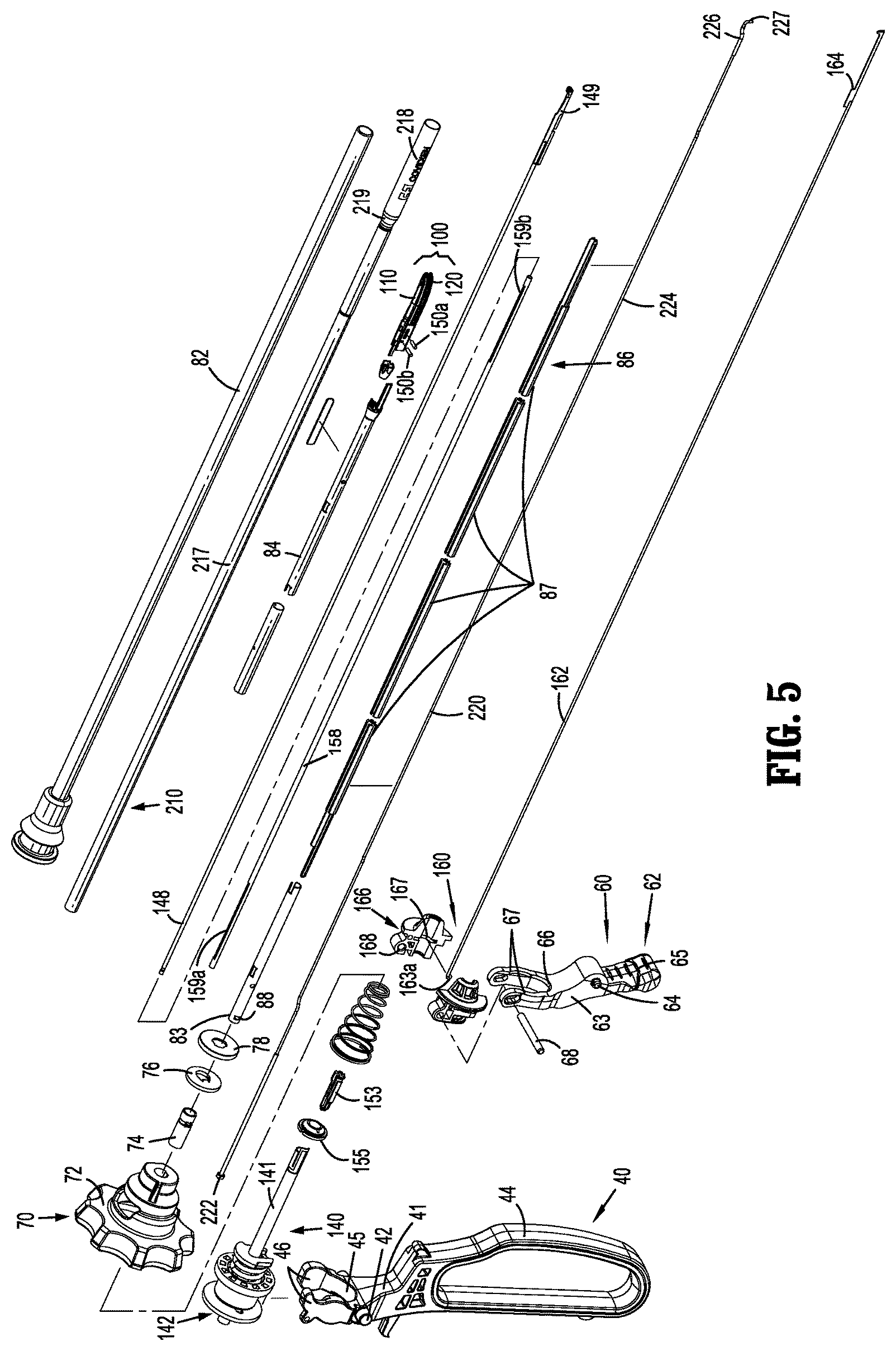
FIG. 5 is an exploded, perspective view of various operable assemblies of the surgical instrument of FIG. 1;
FIG. 6 is a perspective view of the elongated shaft assembly of the surgical instrument of FIG. 1 and the components and assemblies coupled thereto;
FIG. 7 is an enlarged, perspective view of the area of detail indicated as "7" in FIG. 6;
FIG. 8 is a cross-sectional view taken along section line "8-8" of FIG. 7;
FIG. 9 is an enlarged, cross-sectional view of the area of detail indicated as "9" in FIG. 8;
FIG. 10 is an enlarged, cross-sectional view of the area of detail indicated as "10" in FIG. 8;
FIG. 11 is a cross-sectional view taken along section line "11-11" of FIG. 7;
FIG. 12 is an enlarged, cross-sectional view of the area of detail indicated as "12" in FIG. 11;
FIG. 13 is an enlarged, cross-sectional view of the area of detail indicated as "13" in FIG. 11;
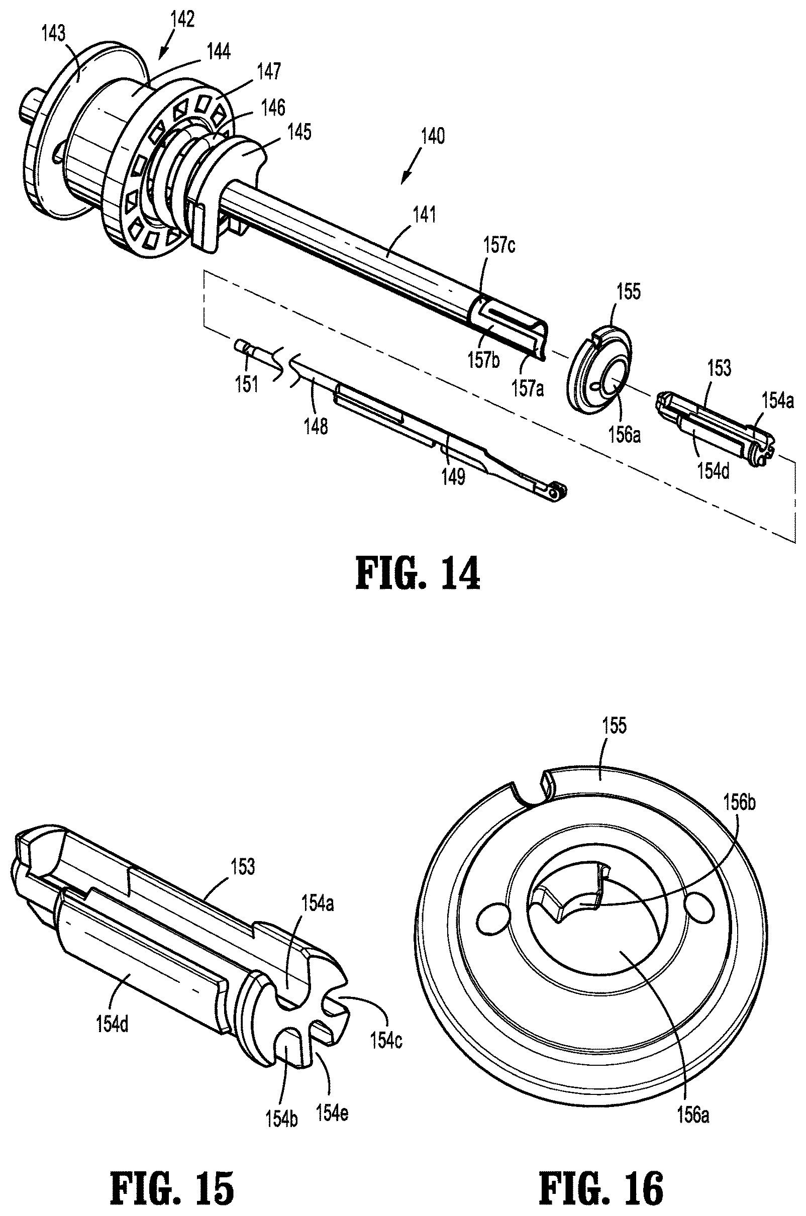
FIG. 14 is an exploded, perspective view of the drive assembly of the surgical instrument of FIG. 1;
FIG. 15 is a perspective view of the drive bar support member of the drive assembly of FIG. 14;
FIG. 16 is a perspective view of the return washer of the drive assembly of FIG. 14;
FIG. 17-19 are perspective views illustrating assembly of the drive assembly of FIG. 14;
FIG. 20 is an enlarged, perspective view of the area of detail indicates as "20" in FIG. 10;
FIG. 21 is a cross-sectional view taken along section line "21-21" of FIG. 20;
FIG. 22 is a perspective view of the rotation assembly and the drive assembly of the surgical instrument of FIG. 1;
FIG. 23 is an exploded, perspective view of the rotation assembly and a portion of the drive assembly of FIG. 22;
FIG. 24 is a perspective view of the retainer of the drive assembly of FIG. 22;
FIG. 25 is a perspective view of the clip of the drive assembly of FIG. 22;
FIG. 26 is an exploded, perspective view of the proximal tube of the elongated shaft assembly of FIG. 6 and the rotation knob of the rotation assembly of FIG. 22;
FIG. 27 is a cross-sectional view taken across section line "28-28" in FIG. 22, except that the clip of the elongated shaft assembly is disengaged;
FIG. 28 is a cross-sectional view taken across section line "28-28" in FIG. 22, wherein the clip of the elongated shaft assembly is engaged;
FIG. 29 is an enlarged, cross-sectional view of the area indicated as "29" in FIG. 13;
FIG. 30 is an exploded, perspective view of the drive assembly and rotation assembly of the surgical instrument of FIG. 1 with another clip configured to facilitate engagement therebetween;
FIG. 31 is a side view of the clip of FIG. 30;
FIG. 32 is a cross-sectional view illustrating the clip of FIG. 30 engaging the drive assembly and rotation assembly with one another;
FIG. 33 is a perspective view of the distal tube of another elongated shaft assembly configured for use with the surgical instrument of FIG. 1;
FIG. 34 is an front view of the distal tube of FIG. 33;
FIG. 35 is a perspective view of the proximal tube of the elongated shaft assembly of FIG. 33;
FIG. 36 is a front view of the proximal tube of FIG. 35;
FIG. 37 is a perspective view of the distal end of a surgical instrument incorporating the distal and proximal tubes of FIGS. 33 and 35, respectively, with portions removed;
FIG. 38 is an enlarged, perspective view of the area of detail indicated as "38" in FIG. 37;
FIG. 39 is an enlarged, perspective view of the area of detail indicated as "39" in FIG. 37; and
FIG. 40 is a front view of the proximal tube of FIG. 35 illustrating positioning of an energizable member extending therethrough.
DETAILED DESCRIPTION
Referring generally to FIGS. 1-5, an endoscopic surgical instrument provided in accordance with the present disclosure is shown generally identified by reference numeral 10. Instrument 10, as described below, is configured to operate in both a bipolar mode, e.g., for grasping, treating, and/or mechanically dissecting tissue, and a monopolar mode, e.g., for treating and/or electrically/electromechanically dissecting tissue. Although the present disclosure is shown and described with respect to instrument 10, the aspects and features of the present disclosure are equally applicable for use with any suitable surgical instrument or portion(s) thereof. Obviously, different connections and considerations apply to each particular instrument and the assemblies and/or components thereof; however, the aspects and features of the present disclosure remain generally consistent regardless of the particular instrument, assemblies, and/or components provided.
Continuing with reference to FIGS. 1-5, instrument 10 generally includes a housing 20, a handle assembly 30, a trigger assembly 60, a rotation assembly 70, an elongated shaft assembly 80, an end effector assembly 100, a drive assembly 140, a knife assembly 160, bipolar and monopolar activation assemblies 170, 180, respectively, a monopolar assembly 200, and a deployment and retraction mechanism 300. As detailed below, elongated shaft assembly 80 extends distally from housing 20, supports end effector assembly 100 at a distal end thereof, drive assembly 140 operably couples handle assembly 30 with end effector assembly 100 to enable selective manipulation of jaw members 110, 120 of end effector assembly 100, knife assembly 160 is operably coupled with trigger assembly 60 to enable selective translation of knife 164 of knife assembly 160 relative to end effector assembly 100, and monopolar assembly 200 is operably coupled with deployment and retraction mechanism 300 to enable selective deployment and retraction of monopolar assembly 200. Rotating assembly 70 is operably coupled to elongated shaft assembly 80 and enables selective rotation of elongated shaft assembly 80, drive assembly 140, trigger assembly 60, end effector assembly 100, and monopolar assembly 200 relative to housing 20, as also detailed below. Bipolar and monopolar activation assemblies 170, 180 enable the appropriate energy to be selectively delivered to end effector assembly 100 and monopolar assembly 200, respectively.
Instrument 10 may also include an electrosurgical cable (not shown) that connects instrument 10 to a generator (not shown) or other suitable power source, although instrument 10 may alternatively be configured as a battery-powered instrument. The electrosurgical cable (not shown) includes wires (not shown) extending therethrough that have sufficient length to extend through housing 20 and/or elongated shaft assembly 80 in order to provide energy to at least one of the electrically-conductive surfaces 112, 122 of jaw members 110, 120, respectively, of end effector assembly 100, e.g., upon activation of bipolar activation switch 172 of bipolar activation assembly 170 in the bipolar mode of operation. Similarly, one or more of the wires of the electrosurgical cable (not shown) extends through housing 20 and/or elongated shaft assembly 80 in order to provide energy to monopolar assembly 200, e.g., upon activation of either of the monopolar activation switches 182 of monopolar activation assembly 180 in the monopolar mode of operation.
Elongated shaft assembly 80 includes a fixed outer tube 82 having a proximal ferrule configured for engagement with housing 20 so as to engage fixed outer tube 82 therewith. Fixed outer tube 82 is a semi-rigid component in that it may be resiliently bent up to 35 degrees from a longitudinal axis thereof without permanent deformation or breaking. Fixed outer tube 82 does not extend distally to end effector assembly 100 but, rather, is spaced-apart therefrom, leaving an exposed section of monopolar assembly 200, although it is contemplated that, in some embodiments, fixed outer tube 82 extends to end effector assembly 100. Elongated shaft assembly 80 further includes a shaft having an inner proximal tube 83, an inner distal tube 84, and an inner tube guide 86 formed from a plurality of tube guide segments 87. Inner proximal tube 83 engages rotation assembly 70, as detailed below, and is disposed about a proximal portion of inner tube guide 86. Inner distal tube 84 engages jaw member 120 at the distal end thereof and is disposed about a distal portion of inner tube guide 86. The components of the shaft, e.g., inner proximal tube 83, inner distal tube 84, and inner tube guide 86, are engaged to one another in any suitable manner, e.g., welding, mechanical fastening, gluing, etc., to form the shaft of elongated shaft assembly 80 and such that rotation of inner proximal tube 83 effects corresponding rotation of inner distal tube 84 and inner tube guide 86. As a result, as will become apparent below, rotation of inner proximal tube 83 via rotation of rotation assembly 70 effects corresponding rotation of end effector assembly 100, drive assembly 140, knife assembly 160, and monopolar assembly 200 relative to housing 20 (FIG. 1) and fixed outer tube 82. At least inner tube guide 86 and, in some embodiments, inner proximal tube 83 and/or inner distal tube 84 are semi-rigid components, similarly as detailed above with respect to fixed outer tube 82, so as to enable resilient bending of elongated shaft assembly 80 up to 35 degrees from the longitudinal axis thereof without permanent deformation or breaking.
As detailed below, elongated shaft assembly 80 is configured to contain and/or support at least a portion of drive bar 148 of drive assembly 140, knife bar 162 of knife assembly 160, and energizable member 220 of monopolar assembly 200 in a non-concentric, non-coaxial arrangement, e.g., wherein drive bar 148, knife bar 162, and energizable member 220 extend alongside one another. Insulative sleeve 210 of monopolar assembly 200 is disposed about drive bar 148, knife bar 162, and energizable member 220 and is likewise non-concentrically and non-coaxially arranged about these components. Insulative sleeve 210 may be semi-rigid, similarly as detailed above, to enable bending. Further, drive bar 148, knife bar 162, and energizable member 220 are at least as flexible as the components of elongated shaft assembly 80, and define diameters significantly smaller than that diameters of the tubes 82, 83, 84, 86 of elongated shaft assembly 80 as well as insulative sleeve 210. For example, the diameters of drive bar 148, knife bar 162, and energizable member 220 may each be between one-third and one-tenth of the diameters of each or any of tubes 82, 83, 84, 86 and insulative sleeve 210. Such a configuration allows for deployment and/or actuation of end effector assembly 100 and monopolar assembly 200 even where elongated shaft assembly 80 (and the components extending therethrough) is resiliently bent up to 35 degrees from the longitudinal axis thereof.
With reference to FIGS. 2, 3, and 5, end effector assembly 100 is disposed at the distal end of elongated shaft assembly 80 and includes opposing jaw members 110, 120 pivotably coupled to one another. Each of the jaw members 110, 120 includes an electrically-conductive surface 112, 122. One or both of surfaces 112, 122 are adapted to connect to the source of energy (not shown), e.g., via the one or more wires (not shown), and are configured to conduct energy through tissue grasped therebetween to treat tissue, e.g., cauterize, coagulate/desiccate, and/or seal tissue. More specifically, in some embodiments, end effector assembly 100 defines a bipolar configuration wherein surface 112 is charged to a first electrical potential and surface 122 is charged to a second, different electrical potential such that an electrical potential gradient is created for conducting energy between surfaces 112, 122 and through tissue grasped therebetween for treating tissue. Bipolar activation switch 172 of bipolar activation assembly 170 (FIG. 1) is operably coupled between the source of energy (not shown) and surfaces 112, 122 via one or more wires (not shown), thus allowing the surgeon to selectively apply energy to surfaces 112, 122 of jaw members 110, 120, respectively, of end effector assembly 100 during a bipolar mode of operation.
End effector assembly 100 is designed as a unilateral assembly, e.g., where jaw member 120 is fixed relative to elongated shaft assembly 80, e.g., jaw member 120 is engaged with inner distal tube 84 of elongated shaft assembly 80, and jaw member 110 is movable relative to elongated shaft assembly 80 and fixed jaw member 120. However, end effector assembly 100 may alternatively be configured as a bilateral assembly, i.e., where both jaw member 110 and jaw member 120 are movable relative to one another and to elongated shaft assembly 80. Further, in some embodiments, a longitudinally-extending knife channel 126 (FIG. 12) may be defined within one or both of jaw members 110, 120 to permit reciprocation of knife 164 (FIG. 5) therethrough, e.g., upon actuation of a trigger 62 of trigger assembly 60 (FIG. 5), to cut tissue grasped between jaw members 110, 120. Jaw members 110, 120 of end effector assembly 100 may otherwise be configured similar to or include any or all of the features of those of the end effector assembly detailed in U.S. Patent Application Publication No. 2014/0257274 to McCullough, Jr. et al., filed on Mar. 4, 2014, the entire contents of which are hereby incorporated herein by reference.
Referring to FIGS. 1, 4, and 5, handle assembly 30 includes movable handle 40 and a fixed handle 50. Fixed handle 50 is integrally associated with housing 20 and movable handle 40 is movable relative to fixed handle 50 between an initial position, wherein movable handle 40 is spaced-apart from fixed handle 50, and a compressed position, wherein movable handle 40 is compressed towards fixed handle 50. More specifically, an intermediate portion 41 of movable handle 40 is pivotably coupled within housing 20 on either side of housing 20 via a split pivot 42. A grasping portion 44 of movable handle 40 extends from split pivot 42 in a first direction, ultimately exiting housing 20 to facilitate grasping and manipulation of movable handle 40 from the exterior of housing 20. A bifurcated portion 45 of movable handle 40 extends from split pivot 42 in a second, opposite direction further into housing 20. Bifurcated portion 45 of movable handle 40 includes a pair of spaced-apart flanges 46.
With reference to FIGS. 5, 7, 10, 13, and 14, drive assembly 140 includes a proximal sleeve 141 that is slidably disposed within housing 20 (see FIG. 4) and configured to operably couple to movable handle 40. Proximal sleeve 141 is coaxial relative to elongated shaft assembly 80 (e.g., tubes 82, 83, 84, 86); however, as detailed below, drive bar 148 of drive assembly 140 is non-coaxial relative to elongated shaft assembly 80. A mandrel assembly 142 of drive assembly 140 operably couples movable handle 40 with proximal sleeve 141 of drive assembly 140. Mandrel assembly 142 is coaxial with proximal sleeve 141 and elongated shaft assembly 80 and includes a proximal collar 143 that is fixedly engaged about proximal sleeve 141, a mandrel 144 slidably disposed about proximal sleeve 141 and positioned distally of proximal collar 143, and a clip 145 engaged about proximal sleeve 141 distally of mandrel 144 such that mandrel 144 is slidably retained between proximal collar 143 and clip 145. A biasing member 146 is positioned about proximal sleeve 141 between mandrel 144 and clip 145 so as to bias mandrel 144 proximally along proximal sleeve 141. Biasing member 146 defines a length such that biasing member 146 is pre-loaded, even when mandrel 144 is in a proximal-most position. Mandrel 144 includes a distal washer 147 integrally formed therewith (although other suitable engagements are also contemplated) so as to define an annular recess between distal washer 147 of mandrel 144 and proximal collar 143 for receipt of spaced-apart flanges 46 of movable handle 40 on either side of mandrel 144. Proximal collar 143, mandrel 144, biasing member 146, and clip 145 may be assembled on proximal sleeve 141 and relative to one another similarly as detailed in U.S. Patent Application Pub. No. 2014/0025071 to Sims et al., filed on Sep. 25, 2013, the entire contents of which are hereby incorporated herein by reference. This assembly method obviates the need for precision joining, such as welding, to achieve proper positioning and spacing between the components.
Referring to FIGS. 5, 9, 12, and 14, drive assembly 140 further includes a drive bar 148 operably coupled to end effector assembly 100 at the distal end of drive bar 148 and operably coupled to proximal sleeve 141 at the proximal end of drive bar 148. More specifically, drive bar 148 defines an arm 149 at the distal end thereof that is configured to receive a cam pin 150a (FIGS. 5, 9, and 12). Cam pin 150a, in turn, is received within corresponding cam slots defined within jaw members 110, 120 such that translation of drive bar 148 relative to end effector assembly 100 translates cam pin 150a through the cam slots to thereby pivot jaw member 110 relative to jaw member 120 about pivot pin 150b (see FIGS. 5, 9, and 12). In particular, distal translation of drive bar 148 urges jaw member 110 to pivot towards the approximated position, while proximal translation of drive bar 148 urges jaw member 110 to pivot towards the spaced-apart position, although the opposite configuration is also contemplated. 158
Drive bar 148 defines a notch 151 therein towards the proximal end thereof that is configured, in conjunction with a drive bar support member 153 and return washer 155, to facilitate operable coupling of drive bar 148 with proximal sleeve 141. Drive assembly 140 further includes a support tube 158 disposed about drive bar 148. Support tube 158 extends about drive bar 148 but defines a shorter length than drive bar 148 such that the distal end of support tube 158 is position proximally of arm 149 and such that the proximal end of support tube 158 is positioned distally of notch 151. Support tube 158 defines a proximal slot 159a and a distal slot 159b. Support tube 158 and drive bar 148 are configured for receipt within a channel defined within inner guide tube 86 of elongated shaft assembly 80 (see FIG. 5).
With reference to FIGS. 14 and 15, drive bar support member 153 defines a drive bar channel 154a configured to receive a portion of drive bar 148, a energizable member channel 154b configured to slidably receive a portion of energizable member 220 (see FIG. 21), a knife bar channel 154c configured to slidably receive a portion of knife bar 162 (see FIG. 21), and an elongated protrusion 154d defining a generally rectangular configuration. Drive bar support member 153 may further define a wire guide channel 154e configured to receive the wires (not shown) extending to jaw members 110, 120 of end effector assembly 100 (FIGS. 2 and 3).
Referring to FIGS. 14 and 16, return washer 155 defines a central aperture 156a and a locking finger 156b extending inwardly into central aperture 156a.
With reference to FIGS. 14 and 17, proximal sleeve 141 defines a cantilever spring arm 157a towards the distal end thereof, an elongated slot 157b defined within cantilever spring arm 157a and shaped complementary to elongated protrusion 154d of drive bar support member 153, and a semi-annular slot 157c disposed at the fixed end of cantilever spring arm 157a.
Turning to FIGS. 14 and 17-21, in order to operably couple drive bar 148 with proximal sleeve 141, the proximal end of drive bar 148 is inserted into drive bar channel 154a of drive bar support member 153 such that notch 151 and the open portion of drive bar channel 154a are oriented in similar directions, as shown in FIG. 17. Next, or prior to the insertion of the proximal end of drive bar 148 into drive bar channel 154a, return washer 155 is slid proximally about proximal sleeve 141 such that proximal sleeve 141 extends through central aperture 156a of return washer 155. More specifically, with locking finger 156b of return washer 155 aligned with cantilever spring arm 157a of drive bar support member 153, return washer 155 is slid proximally about proximal sleeve 141 (deflecting cantilever spring arm 157a inwardly at least initially), with proximal sleeve 141 extending through central aperture 156a of return washer 155 until locking finger 156b passes proximally though elongated slot 157b of proximal sleeve 141 and into semi-annular slot 157c of proximal sleeve 141 (see FIG. 18).
With return washer 155 in position as detailed above, drive bar 148 and drive bar support member 153 are advanced proximally into proximal sleeve 141 and towards return washer 155 such that cantilever spring arm 157a is flexed outwardly. Drive bar 148 and drive bar support member 153 are moved further proximally until elongated protrusion 154d of drive bar support member 153 abuts locking finger 156b of return washer 155. At this point, cantilever spring arm 157a remains outwardly-flexed.
Next, return washer 155 is rotated relative to proximal sleeve 141, drive bar 148, and drive bar support member 153 such that locking finger 156b moves through semi-annular slot 157c of proximal sleeve 141. Return washer 155 is rotated, as indicated by arrow "R" (FIG. 19), to the end of semi-annular slot 157c, such that locking finger 156b is slid into notch 151 of drive bar 148, thereby engaging drive bar 148 and return washer 155.
Once return washer 155 has been rotated as detailed above, locking finger 156b no longer abuts drive bar support member 153. Drive bar support member 153 may then be moved proximally relative to proximal sleeve 141 until elongated slot 157b defined within cantilever spring arm 157a is aligned with elongated protrusion 154d, thus allowing cantilever spring arm 157a to return inwardly under bias so as to capture elongated protrusion 154d within elongated slot 157b to engage drive bar support member 153 with proximal sleeve 141. Further, with drive bar support member 153 and proximal sleeve 141 engaged in this manner, return washer 155 is inhibited from rotating back in the opposite direction of arrow "R" (FIG. 19) due to interference between locking finger 156b and elongated protrusion 154d, and is thus retained in engagement with drive bar 148. In addition, semi-annular slot 157c inhibits longitudinal movement of return washer 155 relative to drive bar support member 153 and proximal sleeve 141. As such, as a result of the above-detailed configuration, proximal sleeve 141, drive bar 148, drive bar support member 153, and return washer 155 are fixedly engaged with one another. This assembly method obviates the need for precision joining, such as welding, to achieve proper positioning and spacing between the components.
Referring to FIGS. 1 and 4-14, drive assembly 140 further includes a biasing member 146 configured for positioning between return washer 155 and rotation wheel 72 of rotation assembly 70 so as to bias drive assembly 140 proximally. The proximal bias of drive assembly 140 biases movable handle towards the initial position. Moving movable handle 40 relative to fixed handle 50 from the initial position to the compressed position urges mandrel 144 distally. During initial movement of movable handle 40, distal movement of mandrel 144 urges biasing member 146 distally which, in turn, moves clip 145, proximal sleeve 141, drive bar 148, drive bar support member 153, and return washer 155 distally. As noted above, distal translation of drive bar 148 urges jaw member 110 to pivot relative to jaw member 120 from the spaced-apart position towards the approximated position to grasp tissue therebetween. However, when the opposing force of tissue resisting compression exceeds the spring force of biasing member 146, further movement of movable handle 40 to urge mandrel 144 distally results in compression of biasing member 146, rather than distal movement of clip 145. As such, clip 145, proximal sleeve 141, drive bar 148, drive bar support member 153, and return washer 155 are maintained in position, and jaw members 110, 120 are not further approximated. In this manner, the pressure applied to tissue grasped between jaw members 110, 120 is regulated.
Referring to FIGS. 1, 4, and 5, trigger 62 of trigger assembly 60 is selectively actuatable relative to housing 20 from an un-actuated position to an actuated position. More specifically, trigger 62 includes an intermediate portion 63 having a split pivot 64 about which trigger 62 is pivotably coupled to housing 20 on either side of housing 20. A toggle portion 65 of trigger 62 extends from split pivot 64 in a first direction, ultimately exiting housing 20 to facilitate manipulation of trigger 62 from the exterior of housing 20. A bifurcated portion 66 of trigger 62 extends from split pivot 64 in a second, opposite direction further into housing 20. Bifurcated portion 66 of trigger 62 includes a pair of spaced-apart arms 67 interconnected via a transverse pin 68.
With additional reference to FIGS. 8-13, knife assembly 160 is operably coupled to trigger 62 such that actuation of trigger 62 from the un-actuated position to the actuated position translates knife 164 of knife assembly 160 from a retracted position, wherein knife 164 is disposed proximally of jaw members 110, 120, to an extended position, wherein knife 164 extends at least partially between jaw members 110, 120 and through the knife channel(s) 126 (FIG. 12) thereof to cut tissue grasped between jaw members 110, 120.
Knife assembly 160 includes knife bar 162, knife 164, and a knife collar 166. Knife collar 166 is coaxial with mandrel assembly 142 and proximal sleeve 141 of drive assembly 140 (see FIG. 5); however knife bar 162, as noted above, extends along-side drive bar 148 (see FIG. 9) in non-coaxial, non-concentric orientation relative thereto. Knife 164 is engaged to and extends distally from knife bar 162. Knife 164 defines a sharpened distal cutting edge to facilitate cutting tissue, although other configurations are also contemplated. Knife bar 162 extends proximally from knife 164 and is configured for receipt within a channel defined within inner guide tube 86 of elongated shaft assembly 80 (see FIG. 5) such that knife bar 162 extends alongside drive bar 148, spaced-apart therefrom. Knife bar 162 extends further proximally from inner guide tube 86 for receipt within knife bar channel 154c of drive bar support member 153 and through proximal sleeve 141 of drive assembly 140. Knife bar 162 defines a proximal foot 163a that extends through an elongated cut-out 163b defined within proximal sleeve 141 (see FIG. 10).
Knife collar 166 is slidably disposed about proximal sleeve 141 of drive assembly 140. Proximal foot 163a of knife bar 162 extends through elongated cut-out 163b of proximal sleeve, as mentioned above, and is received within an annular slot 167 defined within knife collar 166 to rotatably engage knife collar 166 about the proximal end of knife bar 162 with proximal sleeve 141 of drive assembly 140 disposed therebetween. Knife collar 166 further defines a transverse aperture 168 configured to receive transverse pin 68 of trigger assembly 60 to operably couple trigger assembly 60 and knife assembly 160 with one another.
Upon actuation of trigger 62 from the un-actuated position to the actuated position, toggle portion 65 of trigger is pivoted about split pivot 64 in a generally proximal direction while bifurcated portion 66 is pivoted about split pivot 64 in a generally distal direction. Such distal movement of bifurcated portion 66 of trigger 62 urges transverse pin 68 distally, thereby urging knife collar 166 distally. Distal urging of knife collar 166 urges proximal foot 163a of knife bar 162 to translate through elongated cut-out 163b of proximal sleeve 141, thereby translating knife bar 162 and knife 164 distally relative to drive assembly 140, elongated shaft assembly 80, and end effector assembly 100 from the retracted position to the extended position to cut tissue grasped between jaw members 110, 120. In some embodiments, a biasing member (not shown) configured to bias trigger 62 towards the un-actuated position and, thus, knife 164 towards the retracted position, may be provided.
Turning to FIGS. 4, 7, 10, 13, and 22-29, rotation assembly 70 includes rotation wheel 72 that is rotatably disposed but longitudinally constrained within a vertically-oriented slot 26 defined within housing 20 (see FIG. 1). Rotation wheel 72 extends at least partially through slots 26 on either side of housing 20 to enable manipulation of rotation wheel 72 on either exterior side of housing 20 (see FIG. 1). Rotation wheel 72 is engaged about inner proximal tube 83 of elongated shaft assembly 80 such that, as mentioned above, rotation of rotation wheel 72 effects corresponding rotation of inner proximal tube 83, inner distal tube 84, inner tube guide 86, end effector assembly 100, drive assembly 140, knife assembly 160, and monopolar assembly 200 relative to housing 20 (FIG. 1) and fixed outer tube 82.
Rotation assembly 70 further includes an engagement ferrule 74, an engagement clip 76, and a retainer 78 that, as detailed below, cooperate to enable engagement of rotation wheel 72 and fixed outer tube 82 without the need for precision joining, such as welding, while ensuring accurate placement of rotation wheel 72 on inner proximal tube 83 of elongated shaft assembly 80. This positioning is important to ensure proper spacing of rotation wheel 72 relative to end effector assembly 100 such that the proper positionings, clearances, and/or ranges of motions of the various components extending through elongated shaft assembly 80 to end effector assembly 100 are achieved.
Rotation wheel 72, as shown in FIG. 26, includes a body 73a having a manipulation portion 73b and a hub portion 73c and defines an aperture 73d extending therethrough. Manipulation portion 73b extends at least partially through slots 26 on either side of housing 20 to enable manipulation of rotation wheel 72. Hub portion 73c includes a raised block 73e extending inwardly into aperture 73d.
Engagement ferrule 74, as shown in FIG. 26, includes a sleeve body 75a defining a lumen 75b extending therethrough. A longitudinal slot 75c having an open proximal end and a closed distal end is defined through the outer surface of sleeve body 75a. Longitudinal slot 75c defines an enlarged locking portion 75d towards the closed distal end thereof. Longitudinal slot 75c is configured to receive raised block 73e of hub portion 73c of rotation wheel 72, as detailed below. Engagement ferrule 74 further defines an annular recess 75e and a window 75f extending through a portion of annular recess 75e into the interior of sleeve body 75a. Annular recess 75e and window 75f are disposed distally of longitudinal slot 75c.
Engagement clip 76, as shown in FIG. 25, defines a disc-shaped body 77a having an irregular aperture 77b extending therethrough. A tab 77c extends from disc-shaped body 77a into irregular aperture 77b.
Retainer 78, as shown in FIG. 24, defines a disc-shaped body 79a configured similar to or slightly larger than disc-shaped body 77a of engagement clip 76 (FIG. 25). Disc-shaped body 79a defines an aperture 79b therethrough and includes a plurality of spaced-apart tabs 79c extending inwardly into aperture 79b. Tabs 79c may be equally-spaced annularly about aperture 79b, as shown in FIG. 24, or may define any other suitable configuration. Retainer 78 further includes a collar 79d disposed about the outer periphery of disc-shaped body 79a. Collar 79d, as detailed below, is configured to surround disc-shaped body 77a of engagement clip 76 (FIG. 25) so as to engage retainer about engagement clip 76 (FIG. 25) with disc-shaped bodies 77a (FIG. 25), 79a adjacent one another.
Referring to FIGS. 22-29, the assembly of rotation wheel 72 on inner proximal tube 83 of elongated shaft assembly 80 is detailed. Initially, as shown in FIG. 26, engagement ferrule 74 is inserted into aperture 73d of rotation wheel 72 with raised block 73e of rotation wheel 72 aligned with longitudinal slot 75c of engagement ferrule 74. More specifically, upon insertion of engagement ferrule 74 into aperture 73d of rotation wheel 72, sleeve body 75a is deflected so as to enlarge longitudinal slot 75c and enable passage of raised block 73e therethrough. Upon sufficient insertion of engagement ferrule 74 into aperture 73d of rotation wheel 72, raised block 73e reaches enlarged locking portion 75d of longitudinal slot 75c, allowing sleeve body 75a to return to an at-rest, un-deflected position, thereby retaining raised block 73e within enlarged locking portion 75d of longitudinal slot 75c and, thus, engaging engagement ferrule 74 with rotation wheel 72.
Referring to FIGS. 22 and 23, once engagement ferrule 74 is engaged with rotation wheel 72, as detailed above, inner proximal tube 83 of elongated shaft assembly 80 is translated proximally through aperture 79b of retainer 78, irregular aperture 77b of engagement clip 76, and into engagement ferrule 74 such that window 88 defined through inner proximal tube 83 is aligned with window 75f defined within engagement ferrule 74. Thereafter, engagement clip 76 is translated proximally about inner proximal tube 83 and engagement ferrule 74 until tab 77c is aligned above windows 75f, 88, as shown in FIG. 27. Once tab 77c is aligned with windows 75f, 88, engagement clip 76 is moved transversely relative to inner proximal tube 83 and engagement ferrule 74 such that tab 77c extends through windows 75f, 88, thereby engaging inner proximal tube 83 and engagement ferrule 74 with one another, as shown in FIG. 28.
With reference to FIG. 29, in order to secure the engagement between engaging inner proximal tube 83 and engagement ferrule 74, retainer 78 is slid proximally about inner proximal tube 83 and engagement ferrule 74 until collar 79d of retainer 78 is engaged about disc-shaped body 77a of engagement clip 76 to inhibit engagement clip 76 from backing-out of engagement with inner proximal tube 83 and engagement ferrule 74. Simultaneously with or near in time to this engagement of collar 79d about disc-shaped body 77a, spaced-apart tabs 79c of retainer 78 are engaged, e.g., via snap-fit engagement, within annular recess 75e of engagement ferrule 74 to thereby lock retainer 78 in position. This completes the assembly of rotation wheel 72 to inner proximal tube 83.
Turning to FIGS. 30-32, another configuration for assembling rotation wheel 72 on inner proximal tube 83 of elongated shaft assembly 80 is detailed. More specifically, in the configuration illustrated in FIGS. 30-32, rather than using engagement clip 76 and retainer 78 (see FIG. 23), a G-clip 476 is utilized. G-clip 476 includes a body 477a defining a pair of semi-annular cantilever arms 477b, 477c. The free ends of arms 477b, 477c define a gap 477d therebetween. Body 477a further defines a window 477e towards the fixed ends of arms 477b, 477c. A hand 477f including three spaced-apart fingers 477g, 477h, 477i extends from body 477a into window 477e between arms 477b, 477c.
Assembly using G-clip 476 is initially similar to that detailed above. That is, engagement ferrule 74 is first engaged with rotation wheel 72, and then inner proximal tube 83 of elongated shaft assembly 80 is inserted into engagement ferrule 74 such that window 88 defined through inner proximal tube 83 is aligned with window 75f defined within engagement ferrule 74. Once this position has been achieved, G-clip 476 is inserted about engagement ferrule 74 transversely. That is, G-clip 476 is urged transversely about engagement ferrule 74 such that engagement ferrule 74 urges cantilever arms 477b, 477c outwardly relative to one another to widen gap 477d and permit insertion of engagement ferrule 74 therethrough. G-clip 476 is moved further transversely relative to engagement ferrule 74 such that middle finger 477h of hand 477f extends through windows 75f, 88, thereby engaging inner proximal tube 83 and engagement ferrule 74 with one another. Upon reaching this position, the inward bias of arms 477b, 477c into contact with engagement ferrule 74 retains G-clip 476 about engagement ferrule 74, while outer fingers 477g and 477i are biased inwardly into engagement within annular recess 75e of engagement ferrule 74 to retain middle finger 477h in engagement with windows 75f, 88. This completes the assembly of rotation wheel 72 to inner proximal tube 83 using G-clip 476.
With reference to FIGS. 1-5, monopolar assembly 200 includes an insulative sheath 210 and an energizable member 220. Insulative sheath 210 defines a body portion 217 and an enlarged-diametered distal portion 218 extending distally from body portion 217. An annular step 219 is defined at the interface between body portion 217 and enlarged-diametered distal portion 218 of insulative sheath 210. Insulative sheath 210 is movable relative to end effector assembly 100 between a storage position, wherein insulative sheath 210 is disposed proximally of end effector assembly 100, and a use position, wherein insulative sheath 210 is substantially disposed about end effector assembly 100.
Energizable member 220 of monopolar assembly 200 includes a proximal cap 222, a bar 224, and an energizable element 226. Proximal cap 222 is engaged to bar 224 at the proximal end thereof and is operably engaged with deployment and retraction mechanism 300 for selectively deploying and retracting monopolar assembly 200. Bar 224 extends from proximal cap 222 distally through housing 20. Energizable element 226 extends through proximal bar 224 and distally therefrom to a distal tissue-treating portion 227. Energizable element 226 is coupled to the source of energy (not shown) and monopolar activation assembly 180 (FIG. 5) via one or more wires (not shown). Distal tissue-treating portion 227 of energizable element 226 of energizable member 220 functions as the active electrode of monopolar assembly 200. Distal tissue-treating portion 227 may be hook-shaped (as shown), or may define any other suitable configuration, e.g., linear, ball, circular, angled, etc. Proximal bar 224 is insulated so as to facilitate the electrical insulation of energizable element 226 from its surroundings. Energizable member 220 slidably extends through a channel defined within inner guide tube 86 of elongated shaft assembly 80 (see FIG. 5) and energizable member channel 154b of drive bar support member 153 (see FIG. 21).
Referring to FIG. 2, energizable member 220 is disposed on the inner-edge side of jaw members 110, 120 of end effector assembly 100 and is movable relative thereto between a storage position, wherein distal tissue-treating portion 227 of energizable member 220 is positioned more-proximally, and a use position, wherein distal tissue-treating portion 227 of energizable member 220 extends distally from end effector assembly 100 to facilitate treating tissue therewith. In the use position, insulative sheath 210 serves to electrically insulate end effector assembly 100 from distal tissue-treating portion 227 of energizable member 220, while distal tissue-treating portion 227 extends distally from end effector assembly 100. Further, in the use position, energy may be supplied to distal tissue-treating portion 227 of energizable member 220, e.g., via activation of either of the activation switches 182 of monopolar activation assembly 180 (FIG. 1), for treating tissue in the monopolar mode of operation.
Referring also to FIGS. 4 and 5, energizable member 220 is engaged with insulative sleeve 210 such that energizable member 220 and insulative sleeve 210 move together between their respective storage and use positions. Further, proximal cap 222 of energizable member 220 is operably coupled to deployment and retraction mechanism 300, thus enabling deployment and retraction mechanism 300 to translate insulative sheath 210 and energizable member 220 between their respective storage positions, collectively the storage condition of monopolar assembly 200, and their respective use conditions, collectively the use condition of monopolar assembly 200. A more detailed description of monopolar assembly 200, deployment and retraction mechanism 300, and the various safety features associated therewith can be found in U.S. patent application Ser. No. 14/802,582 to Anglese et al., filed on Jul. 17, 2015, the entire contents of which are hereby incorporated herein by reference.
Turning to FIGS. 33-40, another configuration of inner proximal and distal tubes 483, 484 of elongated shaft assembly 80 is shown. Inner proximal and distal tubes 483, 484 are similar to respective inner proximal and distal tubes 83, 84 (FIG. 5), except that inner proximal and distal tubes 483, 484 include cut-outs 485, 486 so as to define C-shaped configurations. The C-shaped configurations of inner proximal and distal tubes 483, 484 and, more specifically, cut-outs 485, 486 thereof, allow for additional spacing to accommodate all of the components extending therethrough. For example, as shown in FIGS. 38-40, energizable member 220 may extend through elongated shaft assembly 80 at least partially within cut-outs 485, 486, rather than being required to be fully disposed within the interior of inner proximal and distal tubes 483, 484. Referring to FIG. 40, this configuration enables movement of energizable member 220 further outwardly relative from the position indicated by the phantom energizable member 220'.
Referring to FIG. 1, the use and operation of instrument 10 is similar to that described in U.S. patent application Ser. No. 14/802,582, previously incorporated herein by reference, except that instrument 10 provides the further benefit of permitting deployment and retraction of monopolar assembly 200 (FIG. 2) between the storage condition and the use condition even when elongated shaft assembly 80 is bent off-axis. Such a situation may arise, for example, when instrument 10 is inserted through a trocar (not shown), or other spatially-constrained device or area, and the surgeon is attempting to manipulate instrument 10 to a desired position. As noted above, bending of elongated shaft assembly 80 up to about 35 degrees off-axis is permitted without limiting deployment and retraction of monopolar assembly 200 (FIG. 2). Manipulation of end effector assembly 100 and deployment of knife 164 (FIG. 5) may likewise be effected without limitation when elongated shaft assembly 80 is bent off-axis up to about 35 degrees.
The various embodiments disclosed herein may also be configured to work with robotic surgical systems and what is commonly referred to as "Telesurgery." Such systems employ various robotic elements to assist the surgeon in the operating room and allow remote operation (or partial remote operation) of surgical instrumentation. Various robotic arms, gears, cams, pulleys, electric and mechanical motors, etc. may be employed for this purpose and may be designed with a robotic surgical system to assist the surgeon during the course of an operation or treatment. Such robotic systems may include remotely steerable systems, automatically flexible surgical systems, remotely flexible surgical systems, remotely articulating surgical systems, wireless surgical systems, modular or selectively configurable remotely operated surgical systems, etc.
The robotic surgical systems may be employed with one or more consoles that are next to the operating theater or located in a remote location. In this instance, one team of surgeons or nurses may prep the patient for surgery and configure the robotic surgical system with one or more of the instruments disclosed herein while another surgeon (or group of surgeons) remotely control the instruments via the robotic surgical system. As can be appreciated, a highly skilled surgeon may perform multiple operations in multiple locations without leaving his/her remote console which can be both economically advantageous and a benefit to the patient or a series of patients.
The robotic arms of the surgical system are typically coupled to a pair of master handles by a controller. The handles can be moved by the surgeon to produce a corresponding movement of the working ends of any type of surgical instrument (e.g., end effectors, graspers, knifes, scissors, etc.) which may complement the use of one or more of the embodiments described herein. The movement of the master handles may be scaled so that the working ends have a corresponding movement that is different, smaller or larger, than the movement performed by the operating hands of the surgeon. The scale factor or gearing ratio may be adjustable so that the operator can control the resolution of the working ends of the surgical instrument(s).
The master handles may include various sensors to provide feedback to the surgeon relating to various tissue parameters or conditions, e.g., tissue resistance due to manipulation, cutting or otherwise treating, pressure by the instrument onto the tissue, tissue temperature, tissue impedance, etc. As can be appreciated, such sensors provide the surgeon with enhanced tactile feedback simulating actual operating conditions. The master handles may also include a variety of different actuators for delicate tissue manipulation or treatment further enhancing the surgeon's ability to mimic actual operating conditions.
From the foregoing and with reference to the various drawing figures, those skilled in the art will appreciate that certain modifications can also be made to the present disclosure without departing from the scope of the same. While several embodiments of the disclosure have been shown in the drawings, it is not intended that the disclosure be limited thereto, as it is intended that the disclosure be as broad in scope as the art will allow and that the specification be read likewise. Therefore, the above description should not be construed as limiting, but merely as exemplifications of particular embodiments. Those skilled in the art will envision other modifications within the scope and spirit of the claims appended hereto.
* * * * *
D00000
D00001
D00002
D00003
D00004
D00005
D00006
D00007
D00008
D00009
D00010
D00011
D00012

D00013

D00014

D00015

D00016

D00017

D00018

D00019

XML
uspto.report is an independent third-party trademark research tool that is not affiliated, endorsed, or sponsored by the United States Patent and Trademark Office (USPTO) or any other governmental organization. The information provided by uspto.report is based on publicly available data at the time of writing and is intended for informational purposes only.
While we strive to provide accurate and up-to-date information, we do not guarantee the accuracy, completeness, reliability, or suitability of the information displayed on this site. The use of this site is at your own risk. Any reliance you place on such information is therefore strictly at your own risk.
All official trademark data, including owner information, should be verified by visiting the official USPTO website at www.uspto.gov. This site is not intended to replace professional legal advice and should not be used as a substitute for consulting with a legal professional who is knowledgeable about trademark law.