Substantially rigid and stable endoluminal surgical suite for treating a gastrointestinal lesion
Piskun , et al. Ja
U.S. patent number 10,537,238 [Application Number 15/469,422] was granted by the patent office on 2020-01-21 for substantially rigid and stable endoluminal surgical suite for treating a gastrointestinal lesion. This patent grant is currently assigned to Boston Scientific Scimed, Inc.. The grantee listed for this patent is Boston Scientific Scimed, Inc.. Invention is credited to Boaz Manash, Dima Pinhasov, Gregory Piskun, Dan Rottenberg.


View All Diagrams
| United States Patent | 10,537,238 |
| Piskun , et al. | January 21, 2020 |
Substantially rigid and stable endoluminal surgical suite for treating a gastrointestinal lesion
Abstract
Exemplary embodiments of devices and method for affecting at least one anatomical tissue can be provided. A configuration can be provided that includes a structure which is expandable (i) having and/or (ii) forming at least one opening or a working space through which the anatomical tissue(s) is placed in the structure. For example, the structure, prior to being expanding, can have at least one partially rigid portion. In addition, or as an alternative, upon a partial or complete expansion thereof, the structure can be controllable to have a plurality of shapes. Further, the structure can be controllable to provide the working space with multiple shapes and/or multiple sizes.
| Inventors: | Piskun; Gregory (Morganville, NJ), Rottenberg; Dan (Haifa, IL), Manash; Boaz (Givat-Ada, IL), Pinhasov; Dima (Naharia, IL) | ||||||||||
|---|---|---|---|---|---|---|---|---|---|---|---|
| Applicant: |
|
||||||||||
| Assignee: | Boston Scientific Scimed, Inc.
(Maple Grove, MN) |
||||||||||
| Family ID: | 44306058 | ||||||||||
| Appl. No.: | 15/469,422 | ||||||||||
| Filed: | March 24, 2017 |
Prior Publication Data
| Document Identifier | Publication Date | |
|---|---|---|
| US 20170196549 A1 | Jul 13, 2017 | |
Related U.S. Patent Documents
| Application Number | Filing Date | Patent Number | Issue Date | ||
|---|---|---|---|---|---|
| 14866695 | Sep 25, 2015 | ||||
| 13726147 | Oct 20, 2015 | 9161746 | |||
| 12970604 | Aug 13, 2013 | 8506479 | |||
| 61287077 | Dec 16, 2009 | ||||
| Current U.S. Class: | 1/1 |
| Current CPC Class: | A61B 1/00089 (20130101); A61B 1/00082 (20130101); A61B 1/018 (20130101); A61B 1/04 (20130101); A61M 25/1011 (20130101); A61B 1/0125 (20130101); A61B 1/32 (20130101); A61B 1/00087 (20130101); A61B 17/3423 (20130101); A61B 17/00234 (20130101); A61B 17/12045 (20130101); A61B 17/0218 (20130101); A61B 1/00154 (20130101); A61B 1/00085 (20130101); A61B 1/00098 (20130101); A61B 1/0051 (20130101); A61B 1/31 (20130101); A61M 29/02 (20130101); A61B 2017/12127 (20130101); A61B 2017/00296 (20130101); A61M 2025/1052 (20130101); A61B 2217/005 (20130101); A61B 2017/345 (20130101); A61M 2029/025 (20130101); A61B 2017/0225 (20130101); A61B 2017/0034 (20130101); A61B 2017/003 (20130101); A61B 2017/3452 (20130101); A61B 2017/00557 (20130101) |
| Current International Class: | A61B 1/32 (20060101); A61B 1/31 (20060101); A61M 29/02 (20060101); A61B 1/012 (20060101); A61B 17/12 (20060101); A61B 17/34 (20060101); A61M 25/10 (20130101); A61B 1/005 (20060101); A61B 17/02 (20060101); A61B 17/00 (20060101); A61B 1/018 (20060101); A61B 1/04 (20060101); A61B 1/00 (20060101) |
References Cited [Referenced By]
U.S. Patent Documents
| 457787 | August 1891 | Leisenring |
| 1621159 | March 1927 | Evans |
| 3517128 | June 1970 | Hines |
| 4040413 | August 1977 | Ohshiro |
| 4083369 | April 1978 | Sinnreich |
| 4224929 | September 1980 | Furihata |
| 4295464 | October 1981 | Shihata |
| 4519403 | May 1985 | Dickhudt |
| 4611594 | September 1986 | Grayhack et al. |
| 4966596 | October 1990 | Kuntz et al. |
| 5025778 | June 1991 | Silverstein et al. |
| 5059199 | October 1991 | Okada et al. |
| 5087265 | February 1992 | Summers |
| 5112310 | May 1992 | Grobe |
| 5197971 | March 1993 | Bonutti |
| 5386817 | February 1995 | Jones |
| 5411508 | May 1995 | Bessler et al. |
| 5423830 | June 1995 | Schneebaum et al. |
| 5655698 | August 1997 | Yoon |
| 5716321 | February 1998 | Kerin et al. |
| 5722103 | March 1998 | Walega |
| 5776097 | July 1998 | Massoud |
| 5947983 | September 1999 | Solar et al. |
| 5954731 | September 1999 | Yoon |
| 5997547 | December 1999 | Nakao et al. |
| 6009877 | January 2000 | Edwards |
| 6042596 | March 2000 | Bonutti |
| 6119913 | September 2000 | Adams et al. |
| 6142931 | November 2000 | Kaji |
| 6142933 | November 2000 | Longo et al. |
| 6203552 | March 2001 | Bagley et al. |
| 6214024 | April 2001 | Houser |
| 6264086 | July 2001 | McGuckin, Jr. |
| 6302311 | October 2001 | Adams et al. |
| 6343731 | February 2002 | Adams et al. |
| 6405732 | June 2002 | Edwards et al. |
| 6423058 | July 2002 | Edwards et al. |
| 6428473 | August 2002 | Leonard et al. |
| 6494881 | December 2002 | Bales et al. |
| 6616603 | September 2003 | Fontana |
| 6695198 | February 2004 | Adams et al. |
| 6805273 | October 2004 | Bilotti et al. |
| 6808491 | October 2004 | Kortenbach et al. |
| 6840423 | January 2005 | Adams et al. |
| 6866178 | March 2005 | Adams et al. |
| 6874669 | April 2005 | Adams et al. |
| 6913610 | July 2005 | Nakao |
| 6923806 | August 2005 | Hooven et al. |
| 6938814 | September 2005 | Sharma et al. |
| 7014646 | March 2006 | Adams |
| 7059331 | June 2006 | Adams et al. |
| 7169115 | January 2007 | Nobis et al. |
| 7276066 | October 2007 | Ouchi |
| 7396329 | July 2008 | Nakao |
| 7445598 | November 2008 | Orban, III |
| 7918787 | April 2011 | Saadat |
| 7959559 | June 2011 | Yamaya |
| 8007508 | August 2011 | Cox |
| 8277373 | October 2012 | Maahs et al. |
| 8506479 | August 2013 | Piskun et al. |
| 8517933 | August 2013 | Mohr |
| 8608652 | December 2013 | Voegele et al. |
| 8764630 | July 2014 | Yamatani |
| 8777961 | July 2014 | Cabrera et al. |
| 8932326 | January 2015 | Riina et al. |
| 8979884 | March 2015 | Milsom et al. |
| 9050004 | June 2015 | Diao et al. |
| 9161746 | October 2015 | Piskun et al. |
| 9168053 | October 2015 | Cox |
| 9259233 | February 2016 | Gruber et al. |
| 9370379 | June 2016 | Osman |
| 9375224 | June 2016 | Jansen |
| 9661984 | May 2017 | Piskun |
| 2001/0004947 | June 2001 | Lemke et al. |
| 2001/0047169 | November 2001 | McGuckin, Jr. et al. |
| 2001/0049497 | December 2001 | Kalloo et al. |
| 2002/0123748 | September 2002 | Edwards et al. |
| 2002/0183593 | December 2002 | Chin et al. |
| 2002/0193660 | December 2002 | Weber et al. |
| 2003/0023143 | January 2003 | Abe et al. |
| 2003/0050663 | March 2003 | Khachin et al. |
| 2003/0074015 | April 2003 | Nakao |
| 2003/0135230 | July 2003 | Massey et al. |
| 2003/0225432 | December 2003 | Baptiste et al. |
| 2003/0225433 | December 2003 | Nakao |
| 2004/0034278 | February 2004 | Adams |
| 2004/0082859 | April 2004 | Schaer |
| 2004/0158263 | August 2004 | McAlister et al. |
| 2004/0204725 | October 2004 | Bayer |
| 2004/0249367 | December 2004 | Saadat et al. |
| 2005/0177105 | August 2005 | Shalev |
| 2005/0234297 | October 2005 | Devierre et al. |
| 2005/0234299 | October 2005 | Eitenmuller et al. |
| 2005/0240147 | October 2005 | Makower et al. |
| 2005/0251111 | November 2005 | Saito et al. |
| 2005/0251177 | November 2005 | Saadat et al. |
| 2005/0272977 | December 2005 | Saadat et al. |
| 2006/0074277 | April 2006 | Yoshida |
| 2006/0100480 | May 2006 | Ewers et al. |
| 2006/0189845 | August 2006 | Maahs |
| 2006/0191975 | August 2006 | Adams et al. |
| 2006/0247662 | November 2006 | Schwartz et al. |
| 2006/0264706 | November 2006 | Piskun |
| 2007/0005093 | January 2007 | Cox |
| 2007/0021778 | January 2007 | Carly |
| 2007/0255207 | November 2007 | Hangai et al. |
| 2007/0287886 | December 2007 | Saadat |
| 2007/0287889 | December 2007 | Mohr |
| 2007/0293724 | December 2007 | Saadat et al. |
| 2008/0045842 | February 2008 | Furnish |
| 2008/0051629 | February 2008 | Sugiyama et al. |
| 2008/0132835 | June 2008 | Nagamatsu et al. |
| 2008/0161645 | July 2008 | Goldwasser et al. |
| 2008/0188868 | August 2008 | Weitzner et al. |
| 2008/0228209 | September 2008 | DeMello et al. |
| 2008/0249534 | October 2008 | Gruber et al. |
| 2008/0269557 | October 2008 | Marescaux et al. |
| 2008/0269559 | October 2008 | Miyamoto et al. |
| 2008/0275300 | November 2008 | Rothe et al. |
| 2008/0300454 | December 2008 | Goto |
| 2009/0018500 | January 2009 | Carter et al. |
| 2009/0030369 | January 2009 | Nagamatsu et al. |
| 2009/0149716 | June 2009 | Diao et al. |
| 2009/0156996 | June 2009 | Milsom et al. |
| 2009/0287046 | November 2009 | Yamatani |
| 2009/0312645 | December 2009 | Weitzner et al. |
| 2010/0010296 | January 2010 | Piskun |
| 2010/0049137 | February 2010 | Fischer, Jr. |
| 2010/0106240 | April 2010 | Duggal et al. |
| 2010/0152590 | June 2010 | Moore et al. |
| 2011/0065985 | March 2011 | Wehrheim |
| 2011/0077498 | March 2011 | McDaniel |
| 2011/0160538 | June 2011 | Ravikumar et al. |
| 2011/0172491 | July 2011 | Piskun et al. |
| 2011/0224494 | September 2011 | Piskun et al. |
| 2011/0245858 | October 2011 | Milsom |
| 2011/0306832 | December 2011 | Bassan et al. |
| 2012/0083797 | April 2012 | Cabrera et al. |
| 2012/0095498 | April 2012 | Stefanchik et al. |
| 2012/0109178 | May 2012 | Edwards et al. |
| 2012/0165604 | June 2012 | Stokes et al. |
| 2013/0090527 | April 2013 | Axon |
| 2013/0172828 | July 2013 | Kappel et al. |
| 2013/0274553 | October 2013 | Piskun et al. |
| 2013/0317303 | November 2013 | Deshmukh et al. |
| 2013/0324795 | December 2013 | Nakajima et al. |
| 2014/0316379 | October 2014 | Sonderegger et al. |
| 2015/0150436 | June 2015 | Cornhill et al. |
| 2015/0157192 | June 2015 | Piskun et al. |
| 2015/0265818 | June 2015 | Piskun et al. |
| 2015/0265268 | September 2015 | Diao et al. |
| 2015/0272564 | October 2015 | Piskun et al. |
| 2015/0351890 | December 2015 | Levin et al. |
| 2016/0038172 | February 2016 | Cox |
| 2016/0081702 | March 2016 | Kan et al. |
| 2016/0106466 | April 2016 | Gruber et al. |
| 2016/0157843 | June 2016 | Dickson et al. |
| 2016/0374658 | December 2016 | Piskun |
| 201200436 | Mar 2009 | CN | |||
| 102018493 | Apr 2011 | CN | |||
| 102695541 | Sep 2012 | CN | |||
| 0163502 | Dec 1985 | EP | |||
| 1588670 | Oct 2005 | EP | |||
| 2512577 | Oct 2012 | EP | |||
| 2365340 | Feb 2002 | GB | |||
| 63292935 | Nov 1988 | JP | |||
| H08-336538 | Dec 1996 | JP | |||
| H08317928 | Dec 1996 | JP | |||
| 2533732 | Apr 1997 | JP | |||
| 10028691 | Mar 1998 | JP | |||
| 2000166936 | Jun 2000 | JP | |||
| 2000325303 | Nov 2000 | JP | |||
| 2001527429 | Dec 2001 | JP | |||
| 2004529708 | Sep 2004 | JP | |||
| 2005046274 | Feb 2005 | JP | |||
| 2007-511247 | May 2007 | JP | |||
| 2008528239 | Jul 2008 | JP | |||
| 2008536552 | Sep 2008 | JP | |||
| 2010511440 | Apr 2010 | JP | |||
| 201275908 | Apr 2012 | JP | |||
| 2013514827 | May 2013 | JP | |||
| 9101773 | Feb 1991 | WO | |||
| 199635469 | Nov 1996 | WO | |||
| 9640347 | Dec 1996 | WO | |||
| 03000139 | Jan 2003 | WO | |||
| 2004103430 | Dec 2004 | WO | |||
| 2006110275 | Oct 2006 | WO | |||
| 2007081601 | Jul 2007 | WO | |||
| 2008011163 | Jan 2008 | WO | |||
| 2009059296 | May 2009 | WO | |||
| 2009076176 | Jun 2009 | WO | |||
| 2009117696 | Sep 2009 | WO | |||
| 2011084616 | Jul 2011 | WO | |||
| 2012068048 | May 2012 | WO | |||
| 2013050880 | Apr 2013 | WO | |||
| 2013192116 | Dec 2013 | WO | |||
| 2014200737 | Dec 2014 | WO | |||
| 2015026968 | Feb 2015 | WO | |||
| 2015191125 | Dec 2015 | WO | |||
Other References
|
European Search Report dated May 3, 2011 for European Patent Application No. 067809411.3. cited by applicant . International Search Report and Written Opinion dated May 6, 2016 for International Application No. PCT/US2016/16911. cited by applicant . European Search Report dated Jun. 1, 2014 for International Application No. PCT/US2014/04029. cited by applicant . Written Opinion dated Jun. 20, 2007 for International Application No. PCT/US06/30464. cited by applicant . The Extended PCT Search Report Application No. PCT/US2016/031355 dated Jul. 18, 2016. cited by applicant . International Search Report and Written Opinion dated May 9, 2018, for PCT/US17/68991 (11 pages). cited by applicant . International Search Report and Written Opinion for PCT application No. PCT/US17/50685. cited by applicant . International Search Report and Written Opinion for application No. PCT/US2014/040429, dated Aug. 1, 2014, 11 pages. cited by applicant . International Search Report and Written Opinion for International Application No. PCT/US18/14388, dated Jun. 19, 2018, 9 pages. cited by applicant . International Search Report and Written Opinion for PCT/US10/60802, dated Aug. 24, 2011, 12 pages. cited by applicant . International Search Report and Written Opinion for International Application No. PCT/US18/21779, dated Jun. 14, 2018, 10 pages. cited by applicant . "Sergey Kantsevoy vs. LumenR LLC, Answer, Affirmative Defenses and Counterclaims", Civil Action No. 17-cv-359 (ELH), filed Feb. 28, 2017, 25 pages. cited by applicant . "Letter from Kurt W. Lockwood, Principal at Kacvinsky Daisak Bluni pllc, to Philip G. Hampton, II c/o Haynes and Boone, LLP" dated Nov. 9, 2018, 16 pages. cited by applicant . "Letter from Philip G. Hampton, II at Haynes and Boone, LLP to Kurt W. Lockwood, Esq. at Kacvinsky Daisak Bluni PLLC", dated Nov. 16, 2018, 2 pages. cited by applicant . "Sergey Kantsevoy v. LumenR LLC Complaint, Civil Action No. 17-359", filed Feb. 7, 2017, 18 pages. cited by applicant . "Sergey Kantsevoy v. LumenR LLC, Dr. Sergey Kantsevoy's Answer to LumenR LLC's Counterclaims", Civil Action No. 17-359 (ELH), filed Mar. 17, 2017, 8 pages. cited by applicant . "Oleg Shikhman vs. Bobcat Endoscopy, LLC (F/K/A/ LumenR LLC) and Gregory Piskun, M.D. Complaint", filed on Oct. 17, 2017, at Judicial District of Fairfield at Bridgeport, 25 pages. cited by applicant . "Oleg Shikhman vs. Bobcat Endoscopy, LLC (F/K/A/ LumenR LLC) and Gregory Piskun, M.D. Reply to Affirmative Defenses, Matters in Avoidance and Answer to Counterclaims", Docket No. X03-HHD-CV17-6087023-S, dated Dec. 12, 2018, 19 pages. cited by applicant . "Oleg Shikhman vs. Bobcat Endoscopy, LLC (F/K/A/ LumenR LLC) and Gregory Piskun, M.D., Answer, Special Defenses and Counterclaims", Docket No. HHD-CV-608 7023-S, dated Sep. 13, 2018, 23 pages. cited by applicant . "Oleg Shikhman vs. Bobcat Endoscopy, LLC (F/K/A/ LumenR LLC) and Gregory Piskun, M.D., First Amended Answer, Affirmative Defenses and Counterclaims", Docket No. X03-HHD-CV17-6087023-S, dated Nov. 9, 2018, 24 pages. cited by applicant . "Letter from Jeffrey M. Chamberlain, Senior Principal at Kacvinsky Daisak Bluni pllc to Michael J. Rye, Esq. c/o Cantor Colburn, LLP", dated Nov. 13, 2018, 3 pages. cited by applicant . "Letter from Michael J. Rye, Partner at Cantor Colburn LLP to Michael Mahoney, CEO at Boston Scientific Corporation", dated Oct. 17, 2017, 3 pages. cited by applicant . Letter from Michael J. Rye, Partner at Cantor Colburn LLP to Jeffrey M. Chamberlain at Kacvinsky Daisak Bluni PLLC, dated Aug. 28, 2018, 2 pages. cited by applicant. |
Primary Examiner: Woodall; Nicholas W
Parent Case Text
CROSS REFERENCE TO RELATED APPLICATION
The application is a continuation of application Ser. No. 14/866,695, filed Sep. 25, 2015 which is a divisional of application Ser. No. 13/726,147, filed Dec. 23, 2012, which is a continuation of application Ser. No. 12/970,604, filed Dec. 16, 2010, now U.S. Pat. No. 8,506,479, which claims the benefit of U.S. Provisional Application No. 61/287,077, filed Dec. 16, 2009. The entire contents of each of these applications are incorporated herein by reference.
Claims
What is claimed is:
1. An endoscopic system, comprising: a multi-lumen endoscope receiving member having a proximal balloon, the proximal balloon inflatable along a distal portion of the multi-lumen endoscope receiving member, a first lumen configured to receive an endoscope therethrough, a second lumen radially spaced from the first lumen to receive a first instrument therethrough and a third lumen radially spaced from the first lumen to receive a second instrument therethrough; a distal balloon positioned distal of the proximal balloon and inflatable beyond a distal end of the multi-lumen endoscope receiving member to form a chamber between the proximal and distal balloons; first and second strips between the proximal and distal balloons; and an endoscope slidably disposed within the first lumen such that a distal tip of the endoscope is extendable into the chamber.
2. The endoscopic system of claim 1, wherein the system is suitable for accessing tissue along a wall of a body lumen, and wherein the chamber comprises an expanded portion of the proximal and distal balloons when inflated.
3. The endoscopic system of claim 1, further comprising a first instrument slidably disposed within the second lumen, wherein a distal end of the first instrument is insertable into the chamber formed between the proximal and distal balloons.
4. The endoscopic system of claim 1, further comprising a handle at a proximal portion of the multi-lumen endoscope receiving member actuatable to move the first and second strips.
5. The endoscopic system of claim 1, further comprising a first instrument slidably disposed within the second lumen and a second instrument slidably disposed within the third lumen.
6. The endoscopic system of claim 5, wherein a distal end of the first and second instruments is configured to bend when extended beyond the distal end of the multi-lumen endoscope receiving member to change a position of the distal end of the first and second instruments within the chamber.
7. The endoscopic system of claim 5, wherein the first and second instruments are independently movable.
8. The endoscopic system of claim 1, wherein the first and second strips are bendable at an intermediate portion to contact a wall of a body lumen.
9. The endoscopic system of claim 1, wherein the second and third lumens are radially spaced from a central longitudinal axis of the endoscope receiving member.
10. The endoscopic system of claim 9, wherein the second and third lumens terminate at distal ends opening into the chamber between the proximal and distal balloons.
11. A multi-lumen endoscope receiving member, comprising: a proximal balloon disposed along a distal portion of the multi-lumen endoscope receiving member, a distal balloon positioned distal of the proximal balloon, a plurality of elongated members extending between the proximal and distal balloons, and a handle for moving the plurality of elongated members; the proximal and distal balloons inflatable to form a chamber therebetween, at least a portion of the chamber extending beyond a distal end of the endoscope receiving member, the endoscope receiving member having a first lumen dimensioned to receive an endoscope and a second lumen dimensioned to receive a first instrument.
12. The endoscope receiving member of claim 11, wherein one or both of a size or shape of the chamber can be adjusted within a body lumen.
13. The endoscope receiving member of claim 11, wherein the elongated members are laterally movable to engage a wall of a body lumen.
14. A method, comprising: a) inserting a multi-lumen endoscope receiving member into a body lumen of a patient, the endoscope receiving member having a proximal balloon, the proximal balloon inflatable along a distal portion of the multi-lumen endoscope receiving member, a distal balloon positioned distal of the proximal balloon and inflatable beyond a distal end of the multi-lumen endoscope receiving member, a plurality of elongated members between the proximal and distal balloons and a first lumen extending through the multi-lumen endoscope receiving member configured to receive an endoscope therethrough; b) inflating the proximal balloon along the distal portion of the endoscope receiving member and inflating the distal balloon beyond the distal end of the endoscope receiving member; c) inserting a first instrument within a second lumen of the endoscope receiving member; d) manipulating a distal end of the first instrument beyond the distal end of the endoscope receiving member; e) inserting a second instrument within a third lumen of the endoscope receiving member; and f) manipulating a distal end of the second instrument beyond a distal end of the endoscope receiving member.
15. The method of claim 14, wherein inflation of the proximal and distal balloons forms a chamber.
16. The method of claim 14, wherein the elongated members are secured at their distal ends.
17. The method of claim 15, further comprising inserting an endoscope within the first lumen to visualize the chamber between the proximal and distal balloons.
18. The method of claim 17, wherein a distal end of the endoscope is movable laterally within the chamber between the proximal and distal balloons.
19. The method of claim 14, wherein inflation of the proximal and distal balloons alters a shape of the body lumen.
Description
FIELD OF THE DISCLOSURE
Exemplary embodiments of the present disclosure relate to arrangements and methods for effecting an endoluminal anatomical structure, and more particularly to arrangements and methods for treatment of gastrointestinal lesions that currently require open abdominal surgery. The exemplary embodiment of at least one of the arrangements can provide an endoluminal colon chamber and a variety of maneuverable operating tools inside that chamber. For example, the exemplary embodiment of such arrangement can function as a miniature operating room inside the colon.
BACKGROUND INFORMATION
Current endoscopic technologies may not facilitate treating colon perforations, large polyps and tumors, and a significant colon bleeding effectively and safely. A gastrointestinal bleeding is a common and potentially life-threatening medical condition, which can complicate any polypectomy (polyp removal), and excision of colonic tumors. A colon perforation can occur when excessive mechanical force or excessive energy is inadvertently applied to a colonic wall. A colon perforation is a life-threatening condition and currently requires major emergency surgery to close the colon perforation and preclude fecal contamination of an abdominal cavity and resulting sepsis.
Consequently, many patients who develop large polyps, colon perforation, colon bleeding and other significant colon pathology currently have to undergo a major surgery and endure a significant operative trauma and, typically, painful and prolong recovery. Currently there are no effective and safe devices and methods for replacing major abdominal surgery in case of colon perforation or when large wide-based polyps need to be removed.
Thus, there may be a need to address at least some of the deficiencies described herein above.
U.S. Provisional Patent Application Ser. No. 61/247,605 filed on Oct. 1, 2009 and entitled "Detachable Balloon Catheter" describes exemplary embodiments of device and method for treatment of a gastrointestinal perforation and/or a gastrointestinal bleeding. The exemplary device can include a balloon catheter that can control bleeding by pressing on a bleeding area or/and prevents the gastrointestinal contents trespassing outside a gastrointestinal lumen into a body cavity by blocking an opening in the luminal wall or blocking the colon distal to the perforation. Such exemplary device can be inserted using an endoscope, and can allow a partial or complete withdrawal of an endoscope, while leaving the balloon at the target area. More specifically, the exemplary device and method can facilitate ceasing a colonic bleeding and blocking a colon perforation.
The Minos Megachannel is a large bore flexible reinforced tube, which is designed to be inserted over the standard colonoscope. After the colonoscope is removed, the tube can be used as a passage for insertion of different instruments into the colon.
Further, conventional endoscopes generally have one to two working channels, which likely do not have independent movements from the main body of the endoscope. As a result, when conventional flexible endoscopic instruments are inserted via such channels into the intestinal lumen, an operator can only manipulate these instruments axially (e.g., forward and backward movements), and possibly somewhat rotationally. In addition, since the conventional instruments can only be advanced from the tip of the endoscope towards the target lesion axially and in front of the endoscopic image, the conventional instruments have only limited functionality.
Accordingly, there may be a need to address at least some of the deficiencies described herein above.
SUMMARY OF EXEMPLARY EMBODIMENTS OF THE PRESENT DISCLOSURE
Exemplary embodiments of the present disclosure can address most if not all of the above-described needs by providing device and method for a treatment of, e.g., a gastrointestinal perforation, bleeding, removal of large polyps, and/or other significant endoluminal pathology, for example, colonic pathology.
According to one exemplary embodiment of the present disclosure, the device can function as a miniature operating room inside the lumen, for example, colon, and providing an operator with advanced endoluminal functionalities replicating capabilities of a surgical suite. The exemplary device of the present disclosure can provide such miniature endoluminal operating room, chamber or at least partial enclosure, and the ability to utilize a variety of articulating surgical instruments, which can operate within, at or around the chamber.
According to one exemplary embodiment of the present disclosure, the exemplary arrangement/device can be introduced after a standard diagnostic colonoscopy is performed. An exemplary balloon guide catheter, as described in U.S. Provisional Patent Application Ser. No. 61/247,605, or a large endoluminal channel such as a Minos Megachannel manufactured by, e.g., Minos Inc., can be used to facilitate the insertion of the exemplary device according to the present disclosure.
In another exemplary embodiment of the present disclosure, the arrangement/device can contain a plurality (e.g., three) primary sections, e.g., a handle, a multi-lumenal tube, and an expandable chamber.
It is possible to utilize endoluminal channels and associated articulating endoluminal instruments with the exemplary embodiments of the arrangement/device. To that end, the exemplary arrangement/device can include a multi-lumen tube. The multi-lumen tube can include lumens for at least two special tools or tool-channels, or three or more special tools and/or tools-channels. In addition, the multi-lumen tube can include other channels, which can be used for, as an example, air, water, vacuum delivery, etc. The exemplary arrangement/device can also include channel for scope and illumination; and lumens for a chamber activation and lumen for a balloon guide catheter as indicated herein.
According to still another exemplary embodiment of the present disclosure, the arrangement/device may also contain a chamber located distally, which can be expanded to different sizes within the colon, thus producing a relatively large working space near the targeted luminal lesion. The exemplary arrangement/device can be structured to manipulate the tools and/or tool-channels in such a way that distal ends of one or more of such tools and/or channels can operate within or at the chamber, and approach the lesion from multiple or even all directions, and using numerous angles. In addition, at least one tool-channel can accommodate a large diameter tool, for example, a special endoscopic stapler.
In a further exemplary embodiment of the present disclosure, the arrangement/device can further contain a control handle, e.g., at or about its proximal end. The handle can be provided in a similar way and/or shape as handles of other endoscopes', while including further more ports, such as, e.g., tool-channels ports, a balloon guide catheter port, a special lever to control the opening and closing of the device chamber, etc.
According to a still further exemplary embodiment of the present disclosure, the arrangement/device can include and/or utilize particular tools or tool-channels. For example, the distal ends of the particular tools and/or tool-channels can be operated in all directions and within all degrees of freedom using the actuating mechanisms, which can be controlled at or about the proximal ends of the device. The exemplary instruments/tools (e.g., grasper(s), scissor(s), dissector(s), others), which can be inserted in the special tools or tool-channels, may be manipulated (e.g., rotated, moved axially forward and backward, bent at the distal end at any desired angles) by manipulating the tool-channels.
In a further exemplary embodiment of the present disclosure, the arrangement/device can facilitate a lateral and/or multi-directional movements of the instruments/tools, in addition to the axial and rotational movements thereof. Since the exemplary tool-channels can be manipulated independently from the main endoscope and other tool-channels, the instruments/tools can approach the lesion from the different and possibly limitless directions. For example, when the endoscopic instruments/tools approach the lesion from the sides in relation to the main longitudinal axis and, hence, without blocking the endoscopic image, a so-called and well-known in laparoscopy "tri-angulation" can be achieved. The tri-angulation can be a preferable technique for achieving the endoscopic arrangement's/device's improved functionality and safety. Such exemplary methodology can mimic the functionality of well-established surgical operating room environments. The exemplary tool-channels can be advanced in the lumen from the working ports of the multi-lumen tube and/or be at least partially pre-fixed to the element(s) of the associated expandable chamber. The exemplary tool-channels can also be advanced directly into the body lumen (e.g., an intestinal lumen), into the chamber space, and/or initially advanced along the element(s) of the chamber and then further into the body lumen or into the chamber space.
As an alternative according to yet another exemplary embodiment of the present disclosure, the arrangement/device, alternatively to the tool-channels or in combination with the tool-channels, can use conventional and/or articulating instruments/tools with at least two degree of freedom.
In addition, according to a further exemplary embodiment of the present disclosure, a method can be provided for using the exemplary arrangement/device in the body lumen (e.g., colon). For example, using such exemplary method, it is possible to perform a standard colonoscopy and identify a lesion that may not be treated using standard endoscopy and techniques. A balloon guide catheter can be inserted, the balloon inflated and the standard colonoscope (the balloon catheter and inflated balloon are left in place) removed. The balloon guide catheter can be used as a guide-wire to facilitate the insertion of the exemplary arrangement/device. The exemplary arrangement/device can be inserted over the balloon guide catheter, e.g., until the chamber is in the proximity to the lesion. The chamber can be deployed and adjusted to certain dimensions. It is possible to readjust the chamber during the procedure, as needed. Further, an operative area can be cleaned with a provided suction catheter. Further, a proximal balloon, a distal balloon or both proximal and distal balloons can be inflated for the treatment area isolation. Tool-channels can be inserted, followed by or in conjunction with an insertion of the instruments/tools into the tool-channels. It is also possible to manipulate the tool-channels to optimize and facilitate the instruments'/tools' approach to the lesion. Further, a procedure can be performed, for example, closing a colonic perforation, removing a large colon polyp or tumor, stopping a bleeding, closing diverticuli, removing an appendix, treating other body luminal lesions.
Further, exemplary embodiments of devices and method for affecting at least one anatomical tissue can be provided. A configuration can be provided that includes a structure which is expandable (i) having and/or (ii) forming at least one opening or a working space through which the anatomical tissue(s) is placed in the structure. For example, the structure, prior to being expanding, can have at least one partially rigid portion. In addition, or as an alternative, upon a partial or complete expansion thereof, the structure can be controllable to have a plurality of shapes. Further, the structure can be controllable to provide the working space with multiple shapes and/or multiple sizes.
According to yet another exemplary embodiment of the present disclosure. prior to the structure being expanded, the structure can have at least one partially rigid portion that is expandable to form a non-cylindrically-shaped working area which can be asymmetrical. Further, an endoscopic arrangement can be included that is structured to be provided in the working area, and that can include a further configuration that facilitates an articulation of a tip portion of the endoscopic arrangement within the working area. The further configuration can include a mechanical bending arm which can facilitate the tip portion to be moved within the working area so as to facilitate a visualization of at least one object in the working area. An arrangement can also be provided which is coupled to the structure, and which can provide (i) at least one lumen and/or (ii) at least one instrument there through to reach the working area. For example, a distance between a tip of the arrangement and a distal portion of the structure that is farthest away from the arrangement can be controllable to adjust a shape and/or a size of the working area.
In still another exemplary embodiment of the present disclosure, upon a complete or partial expansion of the structure, the structure can be controllable to have a plurality of shapes. In addition, the structure can be controllable to provide the working space with multiple shapes and/or multiple sizes. The structure can have an expanded portion and an unexpanded portion, and form an axes of extension of the device, a first distance to a highest point of the expanded portion can be different than a distance to an non-expanded portion. For example, the first distance can be greater than the second distance. The structure can be controllable to adjust the first distance, while maintaining the second distance approximately the same. Further, in an non-expanded state, the configuration can be controllable to provide an articulation thereof in a plurality of directions.
According to a further exemplary embodiment of the present disclosure, a first arrangement can be provided at a distance from the configuration and the anatomical structure(s). In addition, a second arrangement can be provided between the first arrangement and the configuration, and can have at least one lumen that is connected to the first arrangement. Further, a third arrangement can be provided which may be structured to move through the lumen at or near the anatomical structure(s), and which can be configured to be provided in the structure. The lumen(s) can comprise a multi-channel tube, and the structure can be structured to be movable through the multi-channel tube and rigidly connected thereto so as to limit or reduce a movement of the structure with respect to the multi-channel tube. At least one movable camera and an illumination arrangement can be provided within or near the configuration, and movable through the multi-channel tube. At least one movable vacuum catheter and/or irrigation catheter can be provided within or near the structure, and movable through the multi-channel tube.
In one exemplary embodiment, the lumen(s) can comprise a tube channel and/or a tool channel, which is/are movable therein. The tool channel can be axially movable, rotatable, and/or bendable, and can include at least one wire which is configured to bend the tool channel. A distal end of the tool channel can be configured to reach any point inside or near the structure. The tool channel can include at least one wire which can be usable to bend the tube or the tool channel at least in one direction and in at least at one angle which is between 0 and 180 degrees. For example, a distance between the working channel and the structure can be controllable by moving at least one wire in the working channel toward and/or away from the structure. An endoscope can be provided within or near the configuration, and movable through the multi-channel tube to reach the working space. The endoscope can include an image sensor provided on a flexible shaft to visualize at least one portion of the tissue(s).
According to yet a further exemplary embodiment of the present disclosure, the structure can have at least one flexible strip or at least one wire and/or two or more flexible strips or wires. At least one of the strips or wires can have a pre-formed shape to provide the desired geometry of the working space. In addition, at least one balloon can be provided or two or more balloons. At least one of the balloons can be an asymmetric shape and/or a symmetric shape. The balloon(s) can be positioned proximal to the structure. According to one exemplary variant, a first balloon and a second balloon can be provided, where the first balloon is provided distally in relation to the structure, and the second balloon is provided proximally in relation to the structure. The structure can be composed of wires and/or a mesh. Such wires/mesh, prior to being expanded, can have (i) at least one partially rigid portion, (ii) upon a partial or complete expansion thereof, can be controllable to have a plurality of shapes, and/or (iii) can be controllable to provide the working space multiple shapes and/or multiple sizes.
These and other objects, features and advantages of the exemplary embodiment of the present disclosure will become apparent upon reading the following detailed description of the exemplary embodiments of the present disclosure, when taken in conjunction with the appended claims.
BRIEF DESCRIPTION OF THE DRAWINGS
Further objects, features and advantages of the present invention will become apparent from the following detailed description taken in conjunction with the accompanying figures showing illustrative embodiments of the present disclosure, in which:
FIGS. 1a and 1b, are schematic cross-sectional illustrations of an exemplary embodiment of an arrangement/device comprising a multi-lumen extrusion tube, and multiple tubes inside one large tube in accordance with the present disclosure;
FIG. 2a is a perspective view of an exemplary embodiment of the arrangement/device according to the present disclosure comprising which includes a nitinol strips chamber in an open position;
FIG. 2b is a perspective illustration of the arrangement/device of FIG. 2a with the chamber formed by flexible strips in a closed position;
FIG. 2b is a side view of the arrangement/device of FIG. 2a with the chamber formed by flexible strips in another position;
FIG. 2d is a side view of the arrangement/device of FIG. 2a with an overtube covering the chamber that is in the closed position according to an exemplary embodiment of the present disclosure;
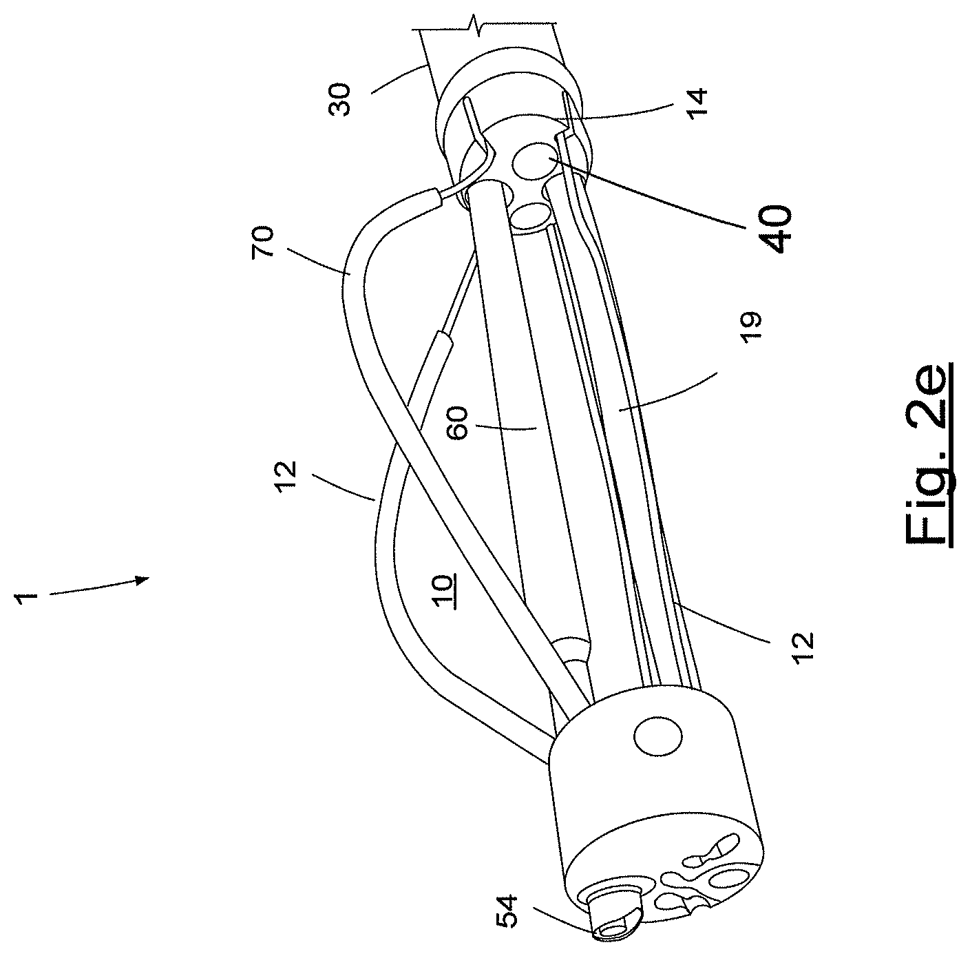
FIG. 2e is a side view illustration of the arrangement/device of FIG. 2a with a scope that is provided in one of the working channels and facilitating a field of view therefor according to another exemplary embodiment of the present disclosure;
FIG. 3 is a perspective view of another exemplary embodiment of the arrangement/device according to the present disclosure which includes the chamber made from two metal strips;
FIG. 4 is a side cross-sectional view of an exemplary embodiment of the arrangement/device according to the present disclosure which includes the chamber made from two asymmetric balloons;
FIG. 5 is a perspective view of another exemplary of another exemplary embodiment of the arrangement/device according to the present disclosure which includes the chamber made from one asymmetric balloon together with the balloon guide catheter;
FIG. 6 is a perspective view of another exemplary of still another exemplary embodiment of the arrangement/device according to the present disclosure which includes the chamber made from metal wires braid;
FIG. 7 is a perspective view of a further exemplary of yet another exemplary embodiment of the arrangement/device according to the present disclosure which includes the nitinol strips chamber with two blocking balloons at both sides;
FIG. 8 is a side view of another exemplary of yet a further exemplary embodiment of the arrangement/device according to the present disclosure which includes the chamber with cameras;
FIG. 9a is a right side perspective view of another exemplary of a further exemplary embodiment of the arrangement/device according to the present disclosure which includes a particular handle;
FIG. 9b is a left side perspective view the exemplary arrangement/device of FIG. 9a;
FIG. 10 is a perspective view of yet another exemplary of yet another exemplary embodiment of the arrangement/device according to the present disclosure which includes a vacuum catheter;
FIG. 11 is a perspective view of yet another exemplary of another exemplary embodiment of the arrangement/device according to the present disclosure which includes a tool-channel;
FIG. 12 are different illustration of a preferred embodiment of still another exemplary of another exemplary embodiment of the arrangement/device according to the present disclosure which includes a tool-channel elevator; and
FIG. 13 a perspective view of yet another exemplary of another exemplary embodiment of the arrangement/device according to the present disclosure which includes the tool-channels inside the chamber thereof.
Throughout the FIGS., the same reference numerals and characters, unless otherwise stated, are used to denote like features, elements, components or portions of the illustrated embodiments. Moreover, while the subject disclosure will now be described in detail with reference to the figures, it is done so in connection with the illustrative embodiments. It is intended that changes and modifications can be made to the described exemplary embodiments without departing from the true scope and spirit of the subject disclosure as defined by the appended claims.
DETAILED DESCRIPTION OF EXEMPLARY EMBODIMENTS
According to one exemplary embodiment of the present disclosure, a device, an arrangement and a method can be provided for treatment of, e.g., conditions associated with body lumen(s) or/and cavities, for example, gastro-intestinal conditions, including but not limited to a gastrointestinal perforation, bleeding, large polyps or/and tumors, diverticuli, appendix, and others.
The exemplary embodiments of the arrangement/device according to the present disclosure can provide various functions, which may be the same and/or similar to the surgical functions provided in the surgical operating room, therefore, thus representing a miniature operating room within a lumen (e.g., of a body), such as, e.g., colon and allowing to replace a major surgery, e.g., an open abdominal surgery.
For example, as shown in FIGS. 2a and 2b, the exemplary embodiment of the arrangement/device 1 according to the present disclosure can provide an endoluminal chamber which can also be at least partial enclosure, such as, e.g., an endoluminal colon or an intra-colon chamber/enclosure, and include various maneuverable operating instruments and/or tools 11 within the chamber 10. The exemplary arrangement/device 1 can be inserted after one or more relevant lesions is/are identified, e.g., during standard colonoscopy. A particular balloon guide catheter 4, e.g., such as described in U.S. Provisional Patent Application Ser. No. 61/247,605 filed on Oct. 1, 2009, or Mega-channel such as Minos Inc. Mega-channel, can be used to facilitate an insertion of the exemplary arrangement/device 1.
According to certain exemplary embodiments of the present disclosure, the arrangement/device 1 can be a particularly-designed endoscope, such as, e.g., a colonoscope. As shown in FIGS. 9a and 9b, according to certain exemplary embodiments, the arrangement/device 1 can include, e.g., an exemplary handle 20 (see FIGS. (see FIGS. 9a and 9b), an exemplary multi-lumen tube 30 (see FIGS. 1a, 1b, 3, 7, 8 and 13), and an exemplary expandable chamber 10 (see FIGS. 5, 7, 10 and 13). In addition, the arrangement/device 1 can include standard and particular exemplary instruments/tools 11 (see FIGS. 8, 12 and 13) and/or exemplary tool channels (see FIG. 13).
As indicated herein above, the exemplary arrangement/device 1 can include the multi-lumen tube 30. Such exemplary multi-lumen tube 30 can be made from a single extrusion polymer tube 31 having multiple lumens {see FIG. 1a}, and/or made in a standard endoscopic equipment configuration using a collection of single or multi-lumen tubes 32 of different sizes that are enclosed by a single, large, flexible tube 33 (see FIG. 1b). External and internal tubes can be simple polymer tubes and/or reinforced tubes or braided tubes, as known in the art. The external tube 33 can have a diameter that is large enough to contain all inner tubes 32 provided for the exemplary arrangement/device 1. The exemplary multi-lumen tube 30 can include at least one lumen, and, e.g., possibly 2 to 4 or more lumens for 2 to 4 or more exemplary instruments/tools 11 and/or tool-channels 40, and possibly additional lumens, for example, for a air insufflation 34, water irrigation 35, vacuum 36, lumen for wiring and/or fibers for cameras and illumination 37, lumen for a balloon guide catheter 4, lumen for chamber expansion control 38, and/or lumen for proximal balloon inflation 39, as shown in the exemplary embodiment of FIG. 1b.
For example, according to particular exemplary embodiments of the present disclosure, the arrangement/device 1 can contain a distal chamber 10 that can be expanded to different sizes inside the colon, thus likely creating relatively large or sufficient working space near the lesion to be treated. The exemplary chamber 10 can provide a space for manipulations of multiple tools and / or tool-channels in such a way that several tools can approach the lesion from all sides and directions, as shown in, e.g., FIGS. 3, 7, 8 and 13. The exemplary multi-lumen tube 30, e.g., having a diameter between 10 mm to 40 mm, can accommodate at least one tool-channel, which can in turn accommodate, e.g., a non-standard instrument, for example, an endoscopic stapler, both having a sufficient size for a particular purposes thereof.
According to one exemplary embodiment of the present disclosure, the exemplary chamber 10 can be constructed from at least one, and possibly two or more flexible metal strips, fibers or wires 12, which can be made from a flexible material, such as, e.g., Nitinol, as shown in FIGS. 2a-2e and 3. These exemplary strips, fibers or wires can be composed of other materials as well, including but not limited to surgical plastic or other materials. The exemplary strips, fibers or wires 12 can be substantially straightened (or slightly-to-moderately bent as needed during steering the device through the lumen) when the chamber 10 (providing a working space) is in non-deployed position (see FIGS. 2a and 2d), and are substantially bent when actuated by a control lever 23 in the handle 20, hence, enlarging the chamber 10 and creating a larger working space inside the colon, as shown in FIGS. 2b, 2c, 2e and 3. For example, pushing or pulling the exemplary strips, fibers or strips 12 can be performed with a tube 19 that can slide in the lumen 38 by pulling and/or pushing the tube 19 proximal end lever 23 in the handle 20, as shown in FIGS. 2a-2e, 3, 9a and 9b. Further, the guide catheter 4 can be inserted inside the tube 19. The exemplary strips 12 can be covered by a soft polymer cover to avoid possible inner colon tissue damage.
According to an exemplary embodiment of the present disclosure, as shown in FIGS. 2a-2e, the chamber 10 it can be deflected by pulling on the exemplary strips, fibers or wires 12, or the chamber 10 can be opened when the exemplary strips, fibers or wires 12 are pushed forward from the handle 30. In thus manner, the exemplary strips, fibers or wires 12 increase working space with in the chamber 30 to facilitate the anatomical structure to be pulled into the chamber 10 by other instruments/tools 11 being manipulated from the handle 30, as described in further details herein, and shown in, e.g., in FIG. 8.
Further, as shown in FIGS. 2c and 2e, the exemplary strips, fibers or wires 12 can be covered with a protective cover portions 70 so as to reduce damage being caused by the exemplary strips, fibers or wires 12 when they are actuated to expand the chamber 10 (i.e., which causes the exemplary strips, fibers or wires 12 to push on the surrounding tissue). As shown in FIG. 2d, the arrangement/device 1 can also include an overtube 65 which can be pushed forward toward the front of the arrangement/device 1 so as to cover the collapsed chamber 10 (e.g., to facilitate insertion and removal and containing the specimen), and pulled back to prepare for the chamber 10 for its expansion. FIG. 2e shows an illustration of the arrangement/device 1 of FIG. 2a with a scope 60 (including a camera and at least one light illuminating source) that is provided in one of the working channels 40 and facilitating a field of view 54 for positioning and propelling the exemplary arrangement/device 1.
When the instrument 1 reaches the desired position within the body, the scope 60 can be retracted inside the chamber 10, e.g., via the working channel 40 to facilitate visualization inside and/or near the chamber 10. According to another exemplary embodiment of the present disclosure, an articulating scope (which can perform similar functions as that of the scope 60) can be provided through one or more of the working channels 40 into the chamber 10. Such articulating scope can be configured to illuminate and/or provide images of the anatomical structure and tools inside and/or near the chamber 10. The articulating scope can have a distal portion that can rotate in 360 degrees and bend to provide an end part thereof so as to illuminate and visualize any portion of the anatomical structure and the tools inside and/or near the chamber 10 at any angle.
In another exemplary embodiment of the present disclosure, as shown in FIG. 7, the strips 12 can be proximally connected to a first cap 14, which can be made from a solid material. The first cap 14 can have multiple holes for most or all lumens 32. The strips 12 can also be distally connected to a second cap 15 which can be smaller in diameter than the first cap 14, to facilitate a passage of large specimens, for example, polyps into the area of the chamber 10. The distal second cap 15 can include a hole for insertion of the balloon guide catheter 4. Alternatively or in addition, the exemplary chamber 10 can be made from two asymmetrical balloons 5, 16, as shown in the exemplary embodiment of FIG. 4. For example, the balloons 5, 16 can create space for the chamber 10 and the exemplary instruments/tools 11 when inflated. Alternatively or in addition, the exemplary chamber 10 can be provided using the proximal balloon 16 and the distal balloon 5, being connected to one another via their attachment to the balloon guide catheter 4, as shown in FIG. 5. Further alternatively or in addition, the exemplary chamber 10 can be provided by a braided metal wire net 17 having an opening 18 at desired location, as shown in FIG. 6.
In another exemplary embodiment of the present disclosure, at least one, and possibly two or more balloons can be used with the chamber 10 that is made from strips 12 made from a bendable material (e.g., metal). The exemplary balloon(s) 5, 16 can assist in blocking and/or isolating the chamber 10 from the rest of the colon, hence, minimizing and/or preventing the inflow and outflow of liquids and solids from and/or to the chamber 10, while the exemplary strips 12 can provide a substantially rigid and stable working space and facilitate treatment of the lesion. For example, as shown in FIG. 7, the first symmetric or asymmetric balloon 16 can be provided in proximal to the chamber 10 or the position of the strips 12. The second balloon 5 can be provided at the position that is distal to the strips 12. Alternatively, the second balloon 5 that can be connected to the guide catheter 4.
According to still another exemplary embodiment of the present disclosure, the arrangement/device 1 can include at least one camera and an illumination apparatus to provide sufficient light to the area of interest. For example, camera or cameras and illuminating component can be movable or fixed in the arrangement/device 1, for example, to the chamber 10. In one exemplary embodiment shown in FIG. 2e, the scope/front camera 50 can be used to facilitate the insertion of the arrangement/device 1 into the colon. Referring to FIG. 8, e.g., at least one, two or more additional and possibly fixed cameras 51 can be positioned so to facilitate image capture at a location of the lesion. Exemplary field views 54 of the cameras 51 can overlap, and such overlap may facilitate visualization if one or more instruments/tools blocks or adversely affects view of one of the cameras. For example, illumination can be provided by a variety of ways, e.g., by LEDs 52, 53. Exemplary front LEDs 52 can be used for the front camera 50, and in-chamber LEDs 53 can be used for the illumination in or at the chamber 10. Alternatively or in addition, a conventional flexible endoscope, having distal bendable section, can be used instead of or together with the fixed camera(s) 51 and illumination via the LEDs 52, 53.
As shown in FIGS. 9a and 9b, the exemplary arrangement/device 1 according to a further exemplary embodiment of the present disclosure can include a control handle 20 at or about its proximal end. The exemplary handle 20 can have similar shape and configuration with respect to other conventional endoscope's handles, while likely having additional channel ports and actuators than standard endoscope. For example, the ports in the handle 20 can include at least one, and possibly 2-4 or even more ports for the tool-channels 21, balloon guide catheter port 22 and particular lever 23 to control the opening and closing of the chamber 10. Additional ports can include, but not limited to, a luer port 24 for a proximal balloon inflation, and a port 26 of a vacuum catheter 25 or an irrigation catheter. The handle 20 can include switches 27, 28 for air insufflations, water irrigation and vacuum activation, as well as switch (not shown) for switching camera(s) between frontal and inner locations.
As illustrated in FIG. 10, the exemplary arrangement/device 1 according to a still further exemplary embodiment of the present disclosure can include a vacuum catheter with a bent tip 25, inserted in a vacuum lumen 36 through a vacuum port 26. The vacuum catheter can operate as a standalone (as describe herein), and/or may be inserted into tool channel 40 and deflect. Further, the vacuum catheter can be manipulated to reach all or most areas inside and around the chamber 10, hence, providing an access for elimination of liquids and solids from and around the chamber 10. In another exemplary embodiment of the present disclosure, the chamber 10 can include bendable and steerable section, which can be actuated at the lever 23, which when pulled, the instrument 1 is articulated, and when pushed, the chamber 10 is opened (or increased in size). Thus, movements of the exemplary arrangement/device 1 in the colon can be facilitated. According to a further exemplary embodiment, a locking mechanism can be provided which can , e.g., rotate one or more times (e.g., counterclockwise or counter-clockwise) to lock the lever 23.
According to still another exemplary embodiment of the present disclosure, the exemplary arrangement/device 1 can include the instruments/tools 11 and/or tool-channels 40, as shown in FIG. 11. When the exemplary instruments/tools 11 are inserted in the tool channels 40, distal ends 41 thereof change the position(s) and/or shapes of the instruments/tools 11, for example, rotated, axially moved, bent at desired angles, whenever the position and shape of the associated tools channels 40 are changed, as shown in FIG. 12. The tool channels 40 can be actuated and manipulated at or about proximal end of the exemplary arrangement/device of the present disclosure. The described maneuverability of the tool-channels 40, for example, their distal ends 41 provide and/or facilitate multidirectional and multiangular approach to the target lesion.
For example, the tool-channels 40 can include at least one, and preferably two, three or more lumen tubes 42, which can be made of polymer, possibly having high torque-ability, low friction, connected at or about their distal ends to an additional section 41, which can have "elevators" 43. The exemplary polymer tube(s) 42 can be reinforced with other materials to change its/their structural or/and functional properties. The elevator 43 can be a flexible bendable section, made, e.g., from a laser cut nitinol tube 44, and/or actuated, e.g., bent, using one or two metal wires 45. The instruments/tools 11 can be inserted in the first (e.g., relatively large) lumen of the tube 42, and the wire 45 can be inserted in the second (e.g., relatively small) lumen of the tube 42.
As shown in FIG. 13, the ability of the tool-channel tubes 42 to move, independently or simultaneously, axially (e.g., pushing, pulling directions), rotate and bend using the elevator 43, facilitates the instruments/tools 11 or/and the tool-channels 40 in reaching any point within and around the chamber 10, and can provide possibly an unlimited range of instrumental freedom within the working space. For example, as shown in FIG. 11, the tool channel 40 can include one or more handles 46 connected to the tube 42 at or about a proximal side of the tube 42, and can be used for a manipulation of the elevator 43, and utilize a port 47 for an insertion of the exemplary instrument/tool.
11. The exemplary tool-channel handle 46 can include a slider or knob 48 which can be used to actuate, e.g., pull and release a wire 45, as shown in FIG. 12. Any standard tool(s) can be used with the exemplary tool-channel(s) 40. Alternatively or in addition, articulating tools having maneuverable distal ends, e.g., with at least two degrees of freedom, can be used.
According to yet a further exemplary embodiment of the present disclosure, a method for implementing the exemplary arrangement/device 1 according to the present disclosure can be provided. Such exemplary method can be utilized as follows: i. Perform a standard colonoscopy and identifying a lesion that may not be treated using standard endoscopy and techniques. ii. Insert a balloon guide catheter, inflating the balloon and removing the standard colonoscope (the balloon catheter and inflated balloon are left in place). The balloon guide catheter can be used as a guide-wire to facilitate the insertion of the exemplary arrangement/device 1. iii. Insert the exemplary arrangement/device lover the balloon guide catheter, until the chamber is in the proximity to the lesion. iv. Deploy and adjust the chamber 10 of the exemplary arrangement/device 1 to preferred dimensions. Readjust the chamber 10 during the procedure as needed. v. Clean an operative area with a provided suction catheter. If desired, inflate a proximal balloon, a distal balloon or both proximal and distal balloons for the treatment area isolation. vi. Insert the tool-channels. vii. Insert the instruments/tools into the tool-channels. Manipulate the tool-channels to optimize and facilitate the instruments/tools approach to the lesion. viii. Perform a procedure, e.g., closing a colonic perforation, removing a large colon polyp or tumor, stopping a bleeding, closing diverticuli, removing an appendix, treating other body luminal lesions.
The foregoing merely illustrates the principles of the present disclosure. Various modifications and alterations to the described embodiments will be apparent to those skilled in the art in view of the teachings herein. For example, more than one of the described exemplary arrangements, radiations and/or systems can be implemented to implement the exemplary embodiments of the present disclosure. It will thus be appreciated that those skilled in the art will be able to devise numerous systems, arrangements and methods which, although not explicitly shown or described herein, embody the principles of the present disclosure and are thus within the spirit and scope of the present disclosure. In addition, to the extent that the prior art knowledge has not been explicitly incorporated by reference herein above, it is explicitly being incorporated herein in its entirety. All publications referenced herein above are incorporated herein by reference in their entireties.
* * * * *
D00000
D00001
D00002
D00003
D00004
D00005
D00006
D00007
D00008
D00009
D00010
D00011
D00012

D00013

D00014

D00015

XML
uspto.report is an independent third-party trademark research tool that is not affiliated, endorsed, or sponsored by the United States Patent and Trademark Office (USPTO) or any other governmental organization. The information provided by uspto.report is based on publicly available data at the time of writing and is intended for informational purposes only.
While we strive to provide accurate and up-to-date information, we do not guarantee the accuracy, completeness, reliability, or suitability of the information displayed on this site. The use of this site is at your own risk. Any reliance you place on such information is therefore strictly at your own risk.
All official trademark data, including owner information, should be verified by visiting the official USPTO website at www.uspto.gov. This site is not intended to replace professional legal advice and should not be used as a substitute for consulting with a legal professional who is knowledgeable about trademark law.