Internal combustion engine having independent combustion chamber
Zhou , et al. Ja
U.S. patent number 10,533,518 [Application Number 15/571,044] was granted by the patent office on 2020-01-14 for internal combustion engine having independent combustion chamber. This patent grant is currently assigned to LIUZHOU ZIJING TECHNOLOGY TRANSFER CENTER CO., LTD., Hu Zhou. The grantee listed for this patent is Liuzhou Zijing Technology Transfer Center Co., Ltd.. Invention is credited to Hanping Yi, Hu Zhou.

| United States Patent | 10,533,518 |
| Zhou , et al. | January 14, 2020 |
Internal combustion engine having independent combustion chamber
Abstract
An internal combustion engine having an independent combustion chamber comprises a combustion chamber (1), an air inlet system (2), a material feeding system (3), and a working system (4). The air inlet system (2) and the combustion chamber (1) are connected together and configured to transport a compressed air to the combustion chamber (1). The material feeding system (3) and the combustion chamber (1) are connected together and configured to transport a fuel to the combustion chamber (1). The combustion chamber (1) has a fixed volume and has no movable wall such as a piston. The fuel continues to be burned in the combustion chamber (1) to generate a high-temperature and high-pressure gas, and chemical energy of the fuel is converted into internal energy of the high-temperature and high-pressure gas. The working system (4) and the combustion chamber (1) are connected together. The piston (21) of the working system (4) works to convert the internal energy of the gas into a mechanical energy.
| Inventors: | Zhou; Hu (Beijing, CN), Yi; Hanping (Tianjin, CN) | ||||||||||
|---|---|---|---|---|---|---|---|---|---|---|---|
| Applicant: |
|
||||||||||
| Assignee: | LIUZHOU ZIJING TECHNOLOGY TRANSFER
CENTER CO., LTD. (Guangxi, CN) Zhou; Hu (Beijing, CN) |
||||||||||
| Family ID: | 53729487 | ||||||||||
| Appl. No.: | 15/571,044 | ||||||||||
| Filed: | April 18, 2016 | ||||||||||
| PCT Filed: | April 18, 2016 | ||||||||||
| PCT No.: | PCT/CN2016/079527 | ||||||||||
| 371(c)(1),(2),(4) Date: | November 01, 2017 | ||||||||||
| PCT Pub. No.: | WO2016/177268 | ||||||||||
| PCT Pub. Date: | November 10, 2016 |
Prior Publication Data
| Document Identifier | Publication Date | |
|---|---|---|
| US 20180163662 A1 | Jun 14, 2018 | |
Foreign Application Priority Data
| May 2, 2015 [CN] | 2015 1 0216187 | |||
| Current U.S. Class: | 1/1 |
| Current CPC Class: | F02M 37/08 (20130101); F02F 1/18 (20130101); F02F 1/004 (20130101); F02G 3/02 (20130101); Y02T 10/12 (20130101); F02G 2258/20 (20130101); F02G 2254/10 (20130101); F02B 23/10 (20130101); F02G 2270/55 (20130101); F02G 2270/02 (20130101); Y02T 10/125 (20130101); F02B 33/06 (20130101); F02G 2270/85 (20130101) |
| Current International Class: | F02G 3/02 (20060101); F02F 1/00 (20060101); F02F 1/18 (20060101); F02B 33/06 (20060101); F02B 23/10 (20060101); F02M 37/08 (20060101) |
References Cited [Referenced By]
U.S. Patent Documents
| 4738236 | April 1988 | Kawamura |
| 5381660 | January 1995 | Loving |
| 6044823 | April 2000 | Watanabe |
| 2001/0045093 | November 2001 | Jacobson |
| 2004/0226523 | November 2004 | Kreuter et al. |
| 2349360 | Nov 1999 | CN | |||
| 2349360 | Nov 1999 | CN | |||
| 101566095 | Oct 2009 | CN | |||
| 102536428 | Jul 2012 | CN | |||
| 102966430 | Mar 2013 | CN | |||
| 104819048 | Aug 2015 | CN | |||
Other References
|
"International Search Report (Form PCT/ISA/210)", dated Jul. 1, 2016, with English translation thereof, pp. 1-4. cited by applicant. |
Primary Examiner: Amick; Jacob M
Assistant Examiner: Brauch; Charles
Attorney, Agent or Firm: Bayramoglu; Gokalp
Claims
What is claimed is:
1. A piston type internal combustion engine, comprising a combustion chamber, an air inlet system, a material feeding system and a working system, wherein the air inlet system, the material feeding system and the working system are all connected with the combustion chamber, the space in the combustion chamber is fixed, the combustion chamber and the working system are separated spatially, chemical energy of a fuel is converted into an internal energy in the combustion chamber, a working medium works through the working system to convert the internal energy into a mechanical energy, the combustion chamber is in the high-temperature and high-pressure state all the time in work, a pressure intensity of intake air is higher than a pressure intensity of the working medium, and the air inlet system and the material feeding system are separately connected to the combustion chamber and are located on opposite sides of the combustion chamber.
2. The internal combustion engine according to claim 1, wherein an outer wall of the combustion chamber is covered with heat-insulation materials for heat preservation.
3. The internal combustion engine according to claim 1, wherein an inner wall of the combustion chamber is coated with fireproof heat-insulation materials.
4. The internal combustion engine according to claim 1, wherein an air compression system and the working system are linked and share a main shaft.
5. The internal combustion engine according to claim 1, wherein the material feeding system is an independent electric material feeding system.
6. The internal combustion engine according to claim 1, wherein a working air chamber is provided with an independent control valve.
7. The internal combustion engine according to claim 6, wherein both the working system and an air compression system are reciprocating piston type systems, and cylinders of the air compression system and the working system are integrally connected.
8. The internal combustion engine according to claim 1, wherein a compressed air buffering device is arranged between an air compressor of the air inlet system and the combustion chamber.
9. The internal combustion engine according to claim 8, wherein the compressed air buffering device has a heating function, and heat of the compressed air buffering device is from a gas exhausted by the working system.
10. An internal combustion power generator, wherein a generated power of the internal combustion power generator is from the internal combustion engine of claim 1.
Description
CROSS-REFERENCE TO RELATED APPLICATION
This application is a 371 of international application of PCT application serial no. PCT/CN2016/079527, filed on Apr. 18, 2016, which claims the priority benefit of China application no. 201510216187.3, filed on May 2, 2015. The entirety of each of the above-mentioned patent applications is hereby incorporated by reference herein and made a part of this specification.
BACKGROUND
Technical Field
The present invention relates to an internal combustion engine, in particular to an internal combustion engine having an independent combustion chamber.
Description of Related Art
A common piston type internal combustion engine is not provided with an independent combustion chamber, fuel is burned in a cylinder to push a piston to work outwards, the energy utilization efficiency of the internal combustion engine is generally 20-40% and can hardly be further improved. The main reason is that the compression ratio and the combustion initial temperature can hardly be further increased.
Fuel is intermittently burned in combustion chambers of common piston-working internal combustion engines. The phenomenon of knocking is likely to be caused if the compression ratio and the combustion initial temperature are increased, and consequentially, the internal combustion engines can be damaged.
SUMMARY
The present invention aims to provide an internal combustion engine according to which the compression ratio and the combustion initial temperature can be increased without causing knocking damage to a working air chamber. The internal combustion engine of the present invention adopts an independent combustion chamber that is made of high-temperature-resistant and high-pressure-resistant materials. Fuel is burned continuously in the combustion chamber to generate a high-temperature and high-pressure gas, and damage to the internal combustion engine caused by the knocking phenomenon is avoided. The internal combustion engine of the present invention is composed of a combustion chamber, an air inlet system, a material feeding system and a working system. The air inlet system is connected with the combustion chamber and configured to transport a compressed air to the combustion chamber. The material feeding system is connected with the combustion chamber and configured to transport a fuel to the combustion chamber. The combustion chamber has a fixed volume and has no movable wall such as a piston. The fuel continues to be burned in the combustion chamber to generate a high-temperature and high-pressure gas, and a chemical energy of the fuel is converted into an internal energy of the high-temperature and high-pressure gas. The working system is connected with the combustion chamber, and the piston of the working system works to convert the internal energy of the gas into a mechanical energy.
The combustion chamber is made of high-temperature-resistant and high-pressure-resistant materials. The high-temperature-resistant and high-pressure-resistant materials can be a high-temperature-resistant special steel, can also be a high-temperature-resistant ceramic, can also be a high-temperature-resistant composite materials, and particularly can be a carbon fiber-ceramic composite materials. The combustion chamber is in the high-temperature and high-pressure state all the time while in work. Furthermore, the outer wall of the combustion chamber can be covered with heat-insulation materials, the inner wall of the combustion chamber can be coated with fireproof heat-insulation materials, and thus heat loss is avoided.
The air inlet system is composed of an air compression system, an air inlet pipeline and an air inlet valve. The air compression system can be linked with the working system and can also work independently. The air compression system can be a single-stage compression system or a multi-stage compression system, and can also be a piston type air compression system or a centrifugal air compression system. The piston type air compression system can be a reciprocating piston type air compression system and can also be a rotor piston type air compression system. The air compression system linked with the working system can be coaxial with the working system and can also not be coaxial with the working system. The reciprocating piston type air compression system linked with the working system can be provided with an independent compression cylinder and can also be provided with a compression cylinder integrally connected with a working cylinder of the working system. The air compression system working independently can be an electric air compression system and can also be an independent internal combustion engine air compression system. The air inlet system can also be provided with a compressed air buffering device between the air compression system and the air inlet valve. The buffering device can be provided with a heating device, the heating device is used for pre-heating the compressed air of the buffering device, and the preheated compressed air enters the combustion chamber through the air inlet valve. The heat of the heating device is from the tail gas exhausted by the working system.
The material feeding system is mainly composed of a fuel storage device and a material feeding pump. Fuel can be liquid fuel and can also be gaseous fuel. The material feeding pump can be a continuous material feeding pump and can also be a pulse material feeding pump, and the material feeding pump can be independent and can also be linked with the working system. The independent material feeding pump can be an electric material feeding pump and can also be a pneumatic material feeding pump. The material feeding pump can be directly connected with the combustion chamber through a material feeding valve, or the material feeding pump is connected with a buffering and heating device and then connected with the combustion chamber through a material feeding valve. According to the material feeding system provided with the buffering and heating device, fuel enters the buffering and heating device through the material feeding pump, the fuel in the buffering device is pre-heated through the buffering and heating device, and the pre-heated fuel enters the combustion chamber through the material feeding valve. The heat of the buffering and heating device is from the tail gas exhausted by the working system.
The working system converts internal energy into mechanical energy, and can be a reciprocating piston type working system, and can also be a rotor piston type working system. The reciprocating piston type working system can be a single-cylinder system and can also be a multi-cylinder system. The multiple cylinders can be aligned linearly or oppositely and can also be arranged in a V shape. The reciprocating piston type working system has only two strokes, one is a working stroke and the other one is an exhausting stroke. Each air chamber provided with a working piston has an independent air inlet control valve, and the flow rate and on-off time of the high-temperature and high-pressure airflow can be controlled according to the requirements.
According to the working principle of the internal combustion engine of the present invention: the air inlet system transports the compressed air to the combustion chamber, the material feeding system transports the fuel to the combustion chamber, the fuel is burned in the combustion chamber, the chemical energy of the fuel is converted into the internal energy of the high-temperature and high-pressure gas, and the piston of the working system works to convert the internal energy of the high-temperature and high-pressure gas into the mechanical energy. The internal combustion engine continues to work, the air inlet system continues to provide the compressed air with the pressure intensity higher than the pressure intensity in the combustion chamber, and the material feeding system continues to provide the fuel with the pressure intensity higher than the pressure intensity in the combustion chamber.
The internal combustion engine of the present invention is relatively simple in structure and extremely convenient to control, the fuel combustion efficiency is high, and the output power density is high.
BRIEF DESCRIPTION OF THE SEVERAL VIEWS OF THE DRAWINGS
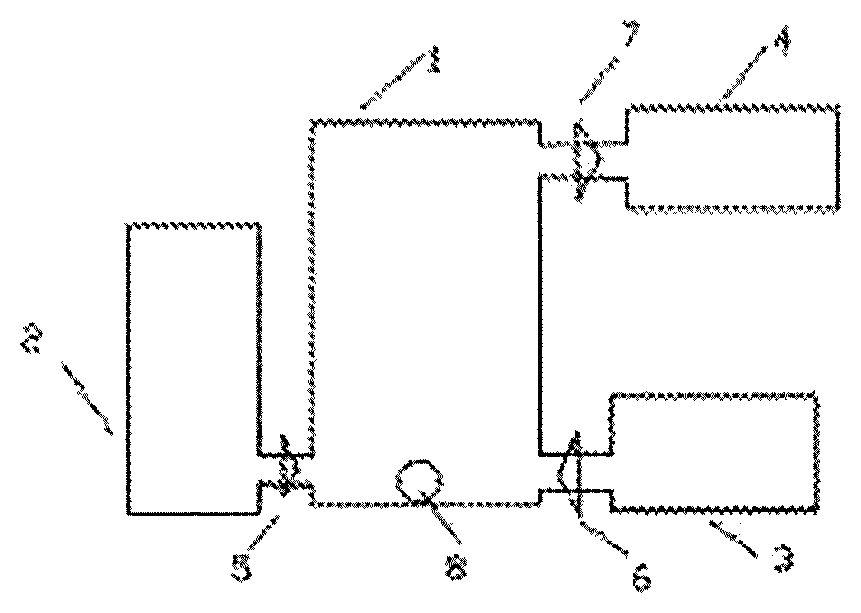
FIG. 1 is a schematic diagram of an internal combustion engine having an independent combustion chamber.
Wherein, 1--combustion chamber, 2--air inlet system, 3--material feeding system, 4--working system, 5--air inlet valve, 6--material feeding valve, 7--working valve, 8--igniter.
FIG. 2 is a schematic diagram of a working air chamber having an independent air inlet control valve.
Wherein, 21--working piston, 22--exhaust valve, 23--air inlet valve.
FIG. 3 is a schematic diagram of a working system and an air compression system in coaxial linkage,
Wherein, 31--main shaft shared by the working system and the air compression system, 32--air compression cylinder of the air inlet system, 33--working cylinder of the working system.
FIG. 4 is a schematic diagram of integrally-connected cylinders and pistons of the working system and the air compression system,
Wherein, 41--integrally-connected cylinders of the working system and the air compression system, 42--integrally-connected pistons of the working system and the air compression system, 43--waste gas exhaust valve of the working system, 44--high-pressure gas inlet valve of the working system, 45--natural air inlet valve of the air inlet system, 46--compressed air outlet valve of the air inlet system
DETAILED DESCRIPTION
Best Embodiment for Implementing the Present Invention
Best Mode of the Present Invention
An internal combustion engine of the present invention is composed of a combustion chamber 1, an air inlet system 2, a material feeding system 3 and a working system 4. The combustion chamber 1 has a fixed volume, and an igniter 8 is arranged in the combustion chamber 1. The air inlet system 2 is connected with the combustion chamber 1 through an air inlet valve 5. The material feeding system 3 is connected with the combustion chamber 1 through a material feeding valve 6. The working system 4 is connected with the combustion chamber 1 through a working valve 7. The working system 4 is a rotor piston type working system, the air inlet system 2 is a single-stage rotor piston type air compression system linked with the working system 4, the material feeding system 3 is an independent electric liquid fuel continuous feeding system, and the combustion chamber 1 is a high-temperature-resistant alloy combustion chamber with the inner wall coated with a fireproof heat-insulation coating.
Embodiment 1
An internal combustion engine of the present invention is composed of a combustion chamber 1, an air inlet system 2, a material feeding system 3 and a working system 4. The combustion chamber 1 has a fixed volume, and an igniter 8 is arranged in the combustion chamber 1. The air inlet system 2 is connected with the combustion chamber 1 through an air inlet valve 5. The material feeding system 3 is connected with the combustion chamber 1 through a material feeding valve 6. The working system 4 is connected with the combustion chamber 1 through a working valve 7. The working system 4 is a single-cylinder reciprocating piston type working system, the air inlet system 2 is a single-cylinder reciprocating piston type air compression system linked with the working system, the material feeding system 3 is an independent electric liquid fuel continuous feeding system, and the combustion chamber 1 is a high-temperature-resistant alloy combustion chamber with the inner wall coated with a fireproof heat-insulation coating.
Embodiment 2
An internal combustion engine of the present invention is composed of a combustion chamber 1, an air inlet system 2, a material feeding system 3 and a working system 4. The combustion chamber 1 has a fixed volume, and an igniter 8 is arranged in the combustion chamber 1. The air inlet system 2 is connected with the combustion chamber 1 through an air inlet valve 5. The material feeding system 3 is connected with the combustion chamber 1 through a material feeding valve 6. The working system 4 is connected with the combustion chamber 1 through a working valve 7. The working system 4 is a reciprocating piston type working system provided with multiple cylinders arranged in a V shape, the air inlet system 2 is a multi-cylinder single-stage reciprocating piston type air compression system linked with the working system, the material feeding system 3 is an independent electric liquid fuel continuous feeding system, and the combustion chamber 1 is a high-temperature-resistant alloy combustion chamber with the inner wall coated with a fireproof heat-insulation coating.
Embodiment 3
An internal combustion engine of the present invention is composed of a combustion chamber 1, an air inlet system 2, a material feeding system 3 and a working system 4. The combustion chamber 1 has a fixed volume, and an igniter 8 is arranged in the combustion chamber 1. The air inlet system 2 is connected with the combustion chamber 1 through an air inlet valve 5. The material feeding system 3 is connected with the combustion chamber 1 through a material feeding valve 6. The working system 4 is connected with the combustion chamber 1 through a working valve 7. The working system 4 is a reciprocating piston type working system provided with multiple linearly-aligned cylinders, the air inlet system 2 is a multi-cylinder single-stage reciprocating piston type air compression system linked with the working system, the material feeding system 3 is an independent electric liquid fuel continuous feeding system, and the combustion chamber 1 is a high-temperature-resistant alloy combustion chamber with the inner wall coated with a fireproof heat-insulation coating.
Embodiment 4
An internal combustion engine of the present invention is composed of a combustion chamber 1, an air inlet system 2, a material feeding system 3 and a working system 4. The combustion chamber 1 has a fixed volume, and an igniter 8 is arranged in the combustion chamber 1. The air inlet system 2 is connected with the combustion chamber 1 through an air inlet valve 5. The material feeding system 3 is connected with the combustion chamber 1 through a material feeding valve 6. The working system 4 is connected with the combustion chamber 1 through a working valve 7. The working system 4 is a rotor piston type working system, the air inlet system 2 is a single-stage rotor piston type air compression system linked with the working system, the material feeding system 3 is an independent electric liquid fuel continuous feeding system, and the combustion chamber 1 is a high-temperature-resistant alloy combustion chamber with the inner wall coated with a fireproof heat-insulation coating.
Embodiment 5
An internal combustion engine of the present invention is composed of a combustion chamber 1, an air inlet system 2, a material feeding system 3 and a working system 4, the combustion chamber 1 has a fixed volume, and an igniter 8 is arranged in the combustion chamber 1. The air inlet system 2 is connected with the combustion chamber 1 through an air inlet valve 5. The material feeding system 3 is connected with the combustion chamber 1 through a material feeding valve 6. The working system 4 is connected with the combustion chamber 1 through a working valve 7. The working system 4 is a reciprocating piston type working system provided with multiple linearly-aligned cylinders, the air inlet system 2 is a multi-cylinder multi-stage reciprocating piston type air compression system linked with the working system, the material feeding system 3 is an independent electric liquid fuel continuous feeding system, and the combustion chamber 1 is a high-temperature-resistant alloy combustion chamber with the inner wall coated with a fireproof heat-insulation coating.
Embodiment 6
An internal combustion engine of the present invention is composed of a combustion chamber 1, an air inlet system 2, a material feeding system 3 and a working system 4. The combustion chamber 1 has a fixed volume, and an igniter 8 is arranged in the combustion chamber 1. The air inlet system 2 is connected with the combustion chamber 1 through an air inlet valve 5. The material feeding system 3 is connected with the combustion chamber 1 through a material feeding valve 6. The working system 4 is connected with the combustion chamber 1 through a working valve 7. The working system 4 is a reciprocating piston type working system provided with multiple linearly-aligned cylinders, the air inlet system 2 is a rotor piston type air compression system linked with the working system, the material feeding system 3 is an independent electric liquid fuel continuous feeding system, and the combustion chamber 1 is a high-temperature-resistant alloy combustion chamber with the inner wall coated with a fireproof heat-insulation coating.
Embodiment 7
An internal combustion engine of the present invention is composed of a combustion chamber 1, an air inlet system 2, a material feeding system 3 and a working system 4. The combustion chamber 1 has a fixed volume, and an igniter 8 is arranged in the combustion chamber 1. The air inlet system 2 is connected with the combustion chamber 1 through an air inlet valve 5. The material feeding system 3 is connected with the combustion chamber 1 through a material feeding valve 6. The working system 4 is connected with the combustion chamber 1 through a working valve 7. The working system 4 is a reciprocating piston type working system provided with multiple linearly-aligned cylinders, the air inlet system 2 is a centrifugal air compression system linked with the working system, the material feeding system 3 is an independent electric liquid fuel continuous feeding system, and the combustion chamber 1 is a high-temperature-resistant alloy combustion chamber with the inner wall coated with a fireproof heat-insulation coating.
Embodiment 8
An internal combustion engine of the present invention is composed of a combustion chamber 1, an air inlet system 2, a material feeding system 3 and a working system 4, the combustion chamber 1 has a fixed volume, and an igniter 8 is arranged in the combustion chamber 1. The air inlet system 2 is connected with the combustion chamber 1 through an air inlet valve 5. The material feeding system 3 is connected with the combustion chamber 1 through a material feeding valve 6. The working system 4 is connected with the combustion chamber 1 through a working valve 7. The working system 4 is a reciprocating piston type working system provided with multiple linearly-aligned cylinders, the air inlet system 2 is an independent electric centrifugal air compression system, the material feeding system 3 is an independent electric liquid fuel continuous feeding system, and the combustion chamber 1 is a high-temperature-resistant alloy combustion chamber with the inner wall coated with a fireproof heat-insulation coating.
Embodiment 9
An internal combustion engine of the present invention is composed of a combustion chamber 1, an air inlet system 2, a material feeding system 3 and a working system 4, the combustion chamber 1 has a fixed volume, and an igniter 8 is arranged in the combustion chamber 1. The air inlet system 2 is connected with the combustion chamber 1 through an air inlet valve 5. The material feeding system 3 is connected with the combustion chamber 1 through a material feeding valve 6. The working system 4 is connected with the combustion chamber 1 through a working valve 7. The working system 4 is a reciprocating piston type working system provided with multiple linearly-aligned cylinders, the air inlet system 2 is an independent electric single-stage reciprocating piston type air compression system, the material feeding system 3 is an independent electric liquid fuel continuous feeding system, and the combustion chamber 1 is a high-temperature-resistant alloy combustion chamber with the inner wall coated with a fireproof heat-insulation coating.
Embodiment 10
An internal combustion engine of the present invention is composed of a combustion chamber 1, an air inlet system 2, a material feeding system 3 and a working system 4. The combustion chamber 1 has a fixed volume, and an igniter 8 is arranged in the combustion chamber 1. The air inlet system 2 is connected with the combustion chamber 1 through an air inlet valve 5. The material feeding system 3 is connected with the combustion chamber 1 through a material feeding valve 6. The working system 4 is connected with the combustion chamber 1 through a working valve 7. The working system 4 is a reciprocating piston type working system provided with multiple linearly-aligned cylinders, the air inlet system 2 is an independent electric multi-stage reciprocating piston type air compression system, the material feeding system 3 is an independent electric liquid fuel continuous feeding system, and the combustion chamber 1 is a high-temperature-resistant alloy combustion chamber with the inner wall coated with a fireproof heat-insulation coating.
Embodiment 11
An internal combustion engine of the present invention is composed of a combustion chamber 1, an air inlet system 2, a material feeding system 3 and a working system 4. The combustion chamber 1 has a fixed volume, and an igniter 8 is arranged in the combustion chamber 1. The air inlet system 2 is connected with the combustion chamber 1 through an air inlet valve 5. The material feeding system 3 is connected with the combustion chamber 1 through a material feeding valve 6. The working system 4 is connected with the combustion chamber 1 through a working valve 7. The working system 4 is a reciprocating piston type working system provided with multiple linearly-aligned cylinders, the air inlet system 2 is an independent electric rotor piston type air compression system, the material feeding system 3 is an independent electric liquid fuel continuous feeding system, and the combustion chamber 1 is a high-temperature-resistant alloy combustion chamber with the inner wall coated with a fireproof heat-insulation coating.
Embodiment 12
An internal combustion engine of the present invention is composed of a combustion chamber 1, an air inlet system 2, a material feeding system 3 and a working system 4, the combustion chamber 1 has a fixed volume, and an igniter 8 is arranged in the combustion chamber 1. The air inlet system 2 is connected with the combustion chamber 1 through an air inlet valve 5. The material feeding system 3 is connected with the combustion chamber 1 through a material feeding valve 6. The working system 4 is connected with the combustion chamber 1 through a working valve 7. The working system 4 is a reciprocating piston type working system provided with multiple linearly-aligned cylinders, the air inlet system 2 is an independent internal combustion engine air compression system, the material feeding system 3 is an independent electric liquid fuel continuous feeding system, and the combustion chamber 1 is a high-temperature-resistant alloy combustion chamber with the inner wall coated with a fireproof heat-insulation coating.
Embodiment 13
An internal combustion engine of the present invention is composed of a combustion chamber 1, an air inlet system 2, a material feeding system 3 and a working system 4. The combustion chamber 1 has a fixed volume, and an igniter 8 is arranged in the combustion chamber 1. The air inlet system 2 is connected with the combustion chamber 1 through an air inlet valve 5. The material feeding system 3 is connected with the combustion chamber 1 through a material feeding valve 6. The working system 4 is connected with the combustion chamber 1 through a working valve 7. The working system 4 is a reciprocating piston type working system provided with multiple linearly-aligned cylinders, the air inlet system 2 is a single-stage multi-cylinder reciprocating piston type air compression system linked with the working system, the material feeding system 3 is an independent electric liquid fuel pulse feeding system, and the combustion chamber 1 is a high-temperature-resistant alloy combustion chamber with the inner wall coated with a fireproof heat-insulation coating.
Embodiment 14
An internal combustion engine of the present invention is composed of a combustion chamber 1, an air inlet system 2, a material feeding system 3 and a working system 4. The combustion chamber 1 has a fixed volume, and an igniter 8 is arranged in the combustion chamber 1. The air inlet system 2 is connected with the combustion chamber 1 through an air inlet valve 5. The material feeding system 3 is connected with the combustion chamber 1 through a material feeding valve 6. The working system 4 is connected with the combustion chamber 1 through a working valve 7. The working system 4 is a reciprocating piston type working system provided with multiple linearly-aligned cylinders, the air inlet system 2 is a single-stage multi-cylinder reciprocating piston type air compression system linked with the working system, the material feeding system 3 is a liquid fuel continuous feeding system in mechanical linkage with the working system, and the combustion chamber 1 is a high-temperature-resistant alloy combustion chamber with the inner wall coated with a fireproof heat-insulation coating.
Embodiment 15
An internal combustion engine of the present invention is composed of a combustion chamber 1, an air inlet system 2, a material feeding system 3 and a working system 4. The combustion chamber 1 has a fixed volume, and an igniter 8 is arranged in the combustion chamber 1. The air inlet system 2 is connected with the combustion chamber 1 through an air inlet valve 5. The material feeding system 3 is connected with the combustion chamber 1 through a material feeding valve 6. The working system 4 is connected with the combustion chamber 1 through a working valve 7. The working system 4 is a reciprocating piston type working system provided with multiple linearly-aligned cylinders, the air inlet system 2 is a single-stage multi-cylinder reciprocating piston type air compression system linked with the working system, the material feeding system 3 is a liquid fuel pulse feeding system in mechanical linkage with the working system, and the combustion chamber 1 is a high-temperature-resistant alloy combustion chamber with the inner wall coated with a fireproof heat-insulation coating.
Embodiment 16
An internal combustion engine of the present invention is composed of a combustion chamber 1, an air inlet system 2, a material feeding system 3 and a working system 4. The combustion chamber 1 has a fixed volume, and an igniter 8 is arranged in the combustion chamber 1. The air inlet system 2 is connected with the combustion chamber 1 through an air inlet valve 5. The material feeding system 3 is connected with the combustion chamber 1 through a material feeding valve 6. The working system 4 is connected with the combustion chamber 1 through a working valve 7. The working system 4 is a reciprocating piston type working system provided with multiple linearly-aligned cylinders, the air inlet system 2 is a single-stage multi-cylinder reciprocating piston type air compression system linked with the working system, the material feeding system 3 is an independent electric gaseous fuel continuous feeding system, and the combustion chamber 1 is a high-temperature-resistant alloy combustion chamber with the inner wall coated with a fireproof heat-insulation coating.
Embodiment 17
An internal combustion engine of the present invention is composed of a combustion chamber 1, an air inlet system 2, a material feeding system 3 and a working system 4. The combustion chamber 1 has a fixed volume, and an igniter 8 is arranged in the combustion chamber 1. The air inlet system 2 is connected with the combustion chamber 1 through an air inlet valve 5. The material feeding system 3 is connected with the combustion chamber 1 through a material feeding valve 6. The working system 4 is connected with the combustion chamber 1 through a working valve 7. The working system 4 is a reciprocating piston type working system provided with multiple linearly-aligned cylinders, the air inlet system 2 is a single-stage multi-cylinder reciprocating piston type air compression system linked with the working system, the material feeding system 3 is an independent electric gaseous fuel pulse feeding system, and the combustion chamber 1 is a high-temperature-resistant alloy combustion chamber with the inner wall coated with a fireproof heat-insulation coating.
Embodiment 18
An internal combustion engine of the present invention is composed of a combustion chamber 1, an air inlet system 2, a material feeding system 3 and a working system 4. The combustion chamber 1 has a fixed volume, and an igniter 8 is arranged in the combustion chamber 1. The air inlet system 2 is connected with the combustion chamber 1 through an air inlet valve 5. The material feeding system 3 is connected with the combustion chamber 1 through a material feeding valve 6. The working system 4 is connected with the combustion chamber 1 through a working valve 7. The working system 4 is a reciprocating piston type working system provided with multiple linearly-aligned cylinders, the air inlet system 2 is a single-stage multi-cylinder reciprocating piston type air compression system linked with the working system, the material feeding system 3 is a gaseous fuel continuous feeding system in mechanical linkage with the working system, and the combustion chamber 1 is a high-temperature-resistant alloy combustion chamber with the inner wall coated with a fireproof heat-insulation coating.
Embodiment 19
An internal combustion engine of the present invention is composed of a combustion chamber 1, an air inlet system 2, a material feeding system 3 and a working system 4. The combustion chamber 1 has a fixed volume, and an igniter 8 is arranged in the combustion chamber 1. The air inlet system 2 is connected with the combustion chamber 1 through an air inlet valve 5. The material feeding system 3 is connected with the combustion chamber 1 through a material feeding valve 6. The working system 4 is connected with the combustion chamber 1 through a working valve 7. The working system 4 is a reciprocating piston type working system provided with multiple linearly-aligned cylinders, the air inlet system 2 is a single-stage multi-cylinder reciprocating piston type air compression system linked with the working system, the material feeding system 3 is a gaseous fuel pulse feeding system in mechanical linkage with the working system, and the combustion chamber 1 is a high-temperature-resistant alloy combustion chamber with the inner wall coated with a fireproof heat-insulation coating.
Embodiment 20
An internal combustion engine of the present invention is composed of a combustion chamber 1, an air inlet system 2, a material feeding system 3 and a working system 4. The combustion chamber 1 has a fixed volume, and an igniter 8 is arranged in the combustion chamber 1. The air inlet system 2 is connected with the combustion chamber 1 through an air inlet valve 5. The material feeding system 3 is connected with the combustion chamber 1 through a material feeding valve 6. The working system 4 is connected with the combustion chamber 1 through a working valve 7. The working system 4 is a reciprocating piston type working system provided with multiple linearly-aligned cylinders, the air inlet system 2 is a single-stage multi-cylinder reciprocating piston type air compression system linked with the working system, the material feeding system 3 is an independent electric liquid fuel continuous feeding system, and the combustion chamber 1 is a high-temperature-resistant ceramic combustion chamber.
Embodiment 21
An internal combustion engine of the present invention is composed of a combustion chamber 1, an air inlet system 2, a material feeding system 3 and a working system 4. The combustion chamber 1 has a fixed volume, and an igniter 8 is arranged in the combustion chamber 1. The air inlet system 2 is connected with the combustion chamber 1 through an air inlet valve 5. The material feeding system 3 is connected with the combustion chamber 1 through a material feeding valve 6. The working system 4 is connected with the combustion chamber 1 through a working valve 7. The working system 4 is a reciprocating piston type working system provided with multiple linearly-aligned cylinders, the air inlet system 2 is a single-stage multi-cylinder reciprocating piston type air compression system linked with the working system, the material feeding system 3 is an independent electric liquid fuel continuous feeding system, and the combustion chamber 1 is a high-temperature-resistant ceramic combustion chamber and is covered with heat-insulation materials.
Embodiment 22
An internal combustion engine of the present invention is composed of a combustion chamber 1, an air inlet system 2, a material feeding system 3 and a working system 4. The combustion chamber 1 has a fixed volume, and an igniter 8 is arranged in the combustion chamber 1. The air inlet system 2 is connected with the combustion chamber 1 through an air inlet valve 5. The material feeding system 3 is connected with the combustion chamber 1 through a material feeding valve 6. The working system 4 is connected with the combustion chamber 1 through a working valve 7. The working system 4 is a reciprocating piston type working system provided with multiple linearly-aligned cylinders, the air inlet system 2 is a single-stage multi-cylinder reciprocating piston type air compression system linked with the working system, the material feeding system 3 is an independent electric liquid fuel continuous feeding system, and the combustion chamber 1 is a ceramic-carbon fiber composite combustion chamber and is covered with heat-insulation materials.
Embodiment 23
An internal combustion engine of the present invention is composed of an internal combustion engine body and a power generator. The internal combustion engine body is composed of a combustion chamber 1, an air inlet system 2, a material feeding system 3 and a working system 4. The combustion chamber 1 has a fixed volume, and an igniter 8 is arranged in the combustion chamber 1. The air inlet system 2 is connected with the combustion chamber 1 through an air inlet valve 5. The material feeding system 3 is connected with the combustion chamber 1 through a material feeding valve 6. The working system 4 is connected with the combustion chamber 1 through a working valve 7. The working system 4 is a reciprocating piston type working system provided with multiple linearly-aligned cylinders, the air inlet system 2 is a single-stage multi-cylinder reciprocating piston type air compression system linked with the working system, the material feeding system 3 is an independent electric liquid fuel continuous feeding system, and the combustion chamber 1 is a high-temperature-resistant alloy combustion chamber with the inner wall coated with a fireproof heat-insulation coating and is covered with heat-insulation materials. The power generator and internal combustion engine body are coaxial.
The above embodiments are only partial applications of the present invention, more combinations can be formed by different combustion chambers, different air inlet systems, different material feeding systems and different working systems, and all the combinations can realize the present invention. The internal combustion engine of the present invention can have a higher air compression ratio and a higher initial temperature, the output power can be better adjusted by controlling the working valve, and more energy can be saved.
INDUSTRIAL APPLICATIONS
The internal combustion engine of the present invention can serve as an engine of a motor vehicle and can also serve as a power source of a power generator.
* * * * *
D00000
D00001
XML
uspto.report is an independent third-party trademark research tool that is not affiliated, endorsed, or sponsored by the United States Patent and Trademark Office (USPTO) or any other governmental organization. The information provided by uspto.report is based on publicly available data at the time of writing and is intended for informational purposes only.
While we strive to provide accurate and up-to-date information, we do not guarantee the accuracy, completeness, reliability, or suitability of the information displayed on this site. The use of this site is at your own risk. Any reliance you place on such information is therefore strictly at your own risk.
All official trademark data, including owner information, should be verified by visiting the official USPTO website at www.uspto.gov. This site is not intended to replace professional legal advice and should not be used as a substitute for consulting with a legal professional who is knowledgeable about trademark law.