Methods and devices for treating stroke
Anand , et al. Ja
U.S. patent number 10,531,882 [Application Number 15/397,947] was granted by the patent office on 2020-01-14 for methods and devices for treating stroke. This patent grant is currently assigned to Alcyone Lifesciences, Inc.. The grantee listed for this patent is Alcyone Lifesciences, Inc.. Invention is credited to P J Anand, John Ekholm, Deep Arjun Singh.


View All Diagrams
| United States Patent | 10,531,882 |
| Anand , et al. | January 14, 2020 |
Methods and devices for treating stroke
Abstract
Methods and devices are disclosed herein that allow for infusion and aspiration through a single device. The device can be used to treat a stroke by delivering the device to the site of a blood clot and simultaneously or sequentially infusing a thrombolytic or other drug into the clot and aspirating the dissolving clot from the patient. The methods and devices can advantageously permit more efficient thrombolytic infusion and clot aspiration. Modular systems are also disclosed, as are methods of treating subdural hematoma or other conditions.
| Inventors: | Anand; P J (Lowell, MA), Ekholm; John (Seattle, WA), Singh; Deep Arjun (Cambridge, MA) | ||||||||||
|---|---|---|---|---|---|---|---|---|---|---|---|
| Applicant: |
|
||||||||||
| Assignee: | Alcyone Lifesciences, Inc.
(Lowell, MA) |
||||||||||
| Family ID: | 59236097 | ||||||||||
| Appl. No.: | 15/397,947 | ||||||||||
| Filed: | January 4, 2017 |
Prior Publication Data
| Document Identifier | Publication Date | |
|---|---|---|
| US 20170189040 A1 | Jul 6, 2017 | |
Related U.S. Patent Documents
| Application Number | Filing Date | Patent Number | Issue Date | ||
|---|---|---|---|---|---|
| 62274582 | Jan 4, 2016 | ||||
| Current U.S. Class: | 1/1 |
| Current CPC Class: | A61M 1/008 (20130101); A61M 1/0058 (20130101); A61B 17/22 (20130101); A61M 2210/0693 (20130101); A61B 2017/22084 (20130101); A61B 2017/22082 (20130101); A61B 2017/22079 (20130101); A61B 90/10 (20160201); A61M 2025/0008 (20130101); A61B 2217/007 (20130101); A61M 25/0102 (20130101); A61B 2017/22088 (20130101); A61B 2217/005 (20130101) |
| Current International Class: | A61B 17/22 (20060101); A61M 1/00 (20060101) |
References Cited [Referenced By]
U.S. Patent Documents
| 2830587 | April 1958 | Everett |
| 3460537 | August 1969 | Zeis |
| 3886948 | June 1975 | Hakim |
| 4146029 | March 1979 | Ellinwood, Jr. |
| 4692146 | September 1987 | Hilger |
| 4885945 | December 1989 | Chiodo |
| 4917686 | April 1990 | Bayston et al. |
| 4979284 | December 1990 | McMurtry et al. |
| 5059178 | October 1991 | Ya |
| 5088208 | February 1992 | Wells et al. |
| 5101548 | April 1992 | McMurtry et al. |
| 5190046 | March 1993 | Shturman |
| 5407431 | April 1995 | Botich et al. |
| 5415648 | May 1995 | Malay et al. |
| 5419761 | May 1995 | Narayanan |
| 5484412 | January 1996 | Pierpont |
| 5509910 | April 1996 | Lunn |
| 5590657 | January 1997 | Cain et al. |
| 5620479 | April 1997 | Diederich |
| 5624396 | April 1997 | McNamara et al. |
| 5695518 | December 1997 | Laerum |
| 5720720 | February 1998 | Laske et al. |
| 5782645 | July 1998 | Stobie et al. |
| 5843150 | December 1998 | Dreessen et al. |
| 5868711 | February 1999 | Kramer et al. |
| 5954687 | September 1999 | Baudino |
| 5963367 | October 1999 | Aksyuk et al. |
| 6061587 | May 2000 | Kucharczyk et al. |
| 6176842 | January 2001 | Tachibana et al. |
| 6193963 | February 2001 | Stern et al. |
| 6200291 | March 2001 | Di Pietro |
| 6224566 | May 2001 | Loeb |
| 6309634 | October 2001 | Bankiewicz et al. |
| 6454945 | September 2002 | Weigl et al. |
| 6464662 | October 2002 | Raghavan et al. |
| 6464687 | October 2002 | Ishikawa et al. |
| 6471993 | October 2002 | Shastri et al. |
| 6547779 | April 2003 | Levine et al. |
| 6599274 | July 2003 | Kucharczyk et al. |
| 6610235 | August 2003 | Lebouitz et al. |
| 6626902 | September 2003 | Kucharczyk et al. |
| 6706009 | March 2004 | Diermann et al. |
| 6803568 | October 2004 | Bousse et al. |
| 6953575 | October 2005 | Bankiewicz et al. |
| 6958059 | October 2005 | Zadno-Azizi |
| 7029697 | April 2006 | Segura et al. |
| 7048716 | May 2006 | Kucharczyk et al. |
| 7220269 | May 2007 | Ansel |
| 7316676 | January 2008 | Peyman et al. |
| 7494486 | February 2009 | Mische |
| 7534613 | May 2009 | Bankiewicz et al. |
| 7549989 | June 2009 | Morgan et al. |
| 7588574 | September 2009 | Assell et al. |
| 7662143 | February 2010 | Carrison |
| 7690325 | April 2010 | Henderson et al. |
| 7713269 | May 2010 | Auge, II et al. |
| 7771387 | August 2010 | Porter |
| 7842006 | November 2010 | Wang et al. |
| 7984929 | July 2011 | Gill |
| 8128600 | March 2012 | Gill |
| 8192366 | June 2012 | Mauge et al. |
| 8231600 | July 2012 | von Hoffmann |
| 8282566 | October 2012 | Mauge et al. |
| 8309355 | November 2012 | Bankiewicz et al. |
| 8347696 | January 2013 | Espinosa et al. |
| 8444665 | May 2013 | Tsugita |
| 8539905 | September 2013 | Cady et al. |
| 8602644 | December 2013 | Choi |
| 8790317 | July 2014 | Olbricht et al. |
| 8814853 | August 2014 | Bosel |
| 8992458 | March 2015 | Singh et al. |
| 9255245 | February 2016 | Bernick et al. |
| 9445838 | September 2016 | Wei et al. |
| 9844585 | December 2017 | Olbricht et al. |
| 9919129 | March 2018 | Singh et al. |
| 10065016 | September 2018 | Singh et al. |
| 2001/0005552 | June 2001 | Berg et al. |
| 2002/0055702 | May 2002 | Atala et al. |
| 2002/0055731 | May 2002 | Atala et al. |
| 2002/0091407 | July 2002 | Zadno-Azizi |
| 2002/0099356 | July 2002 | Unger et al. |
| 2002/0138036 | September 2002 | Babaev |
| 2002/0193817 | December 2002 | Lal et al. |
| 2003/0009153 | January 2003 | Brisken et al. |
| 2003/0048969 | March 2003 | Hunter et al. |
| 2003/0093032 | May 2003 | Py et al. |
| 2003/0138403 | July 2003 | Drustrup |
| 2003/0148539 | August 2003 | van Dam et al. |
| 2003/0205947 | November 2003 | Klee et al. |
| 2003/0216685 | November 2003 | Porter |
| 2003/0216714 | November 2003 | Gill |
| 2004/0073114 | April 2004 | Oliver et al. |
| 2004/0106904 | June 2004 | Gonnelli et al. |
| 2004/0176732 | September 2004 | Frazier et al. |
| 2004/0186384 | September 2004 | Babaev |
| 2004/0220543 | November 2004 | Heruth et al. |
| 2004/0260241 | December 2004 | Yamamoto et al. |
| 2005/0035983 | February 2005 | Cruchon-Dupeyrat et al. |
| 2005/0125007 | June 2005 | Gill |
| 2005/0137134 | June 2005 | Gill et al. |
| 2005/0137531 | June 2005 | Prausnitz et al. |
| 2005/0143790 | June 2005 | Kipke et al. |
| 2005/0154297 | July 2005 | Gill |
| 2005/0177117 | August 2005 | Crocker et al. |
| 2005/0190999 | September 2005 | Hunter et al. |
| 2005/0236566 | October 2005 | Liu |
| 2005/0269251 | December 2005 | Cork et al. |
| 2005/0277862 | December 2005 | Anand |
| 2006/0003310 | January 2006 | Klauke et al. |
| 2006/0025752 | February 2006 | Broaddus et al. |
| 2006/0122677 | June 2006 | Vardiman |
| 2006/0135945 | June 2006 | Bankiewicz et al. |
| 2006/0211944 | September 2006 | Mauge et al. |
| 2006/0211945 | September 2006 | Mauge et al. |
| 2006/0211946 | September 2006 | Mauge et al. |
| 2007/0005017 | January 2007 | Alchas et al. |
| 2007/0016041 | January 2007 | Nita |
| 2007/0055180 | March 2007 | Deem et al. |
| 2007/0088295 | April 2007 | Bankiewicz |
| 2007/0123843 | May 2007 | Gill |
| 2007/0128083 | June 2007 | Yantz et al. |
| 2007/0163137 | July 2007 | Hunter et al. |
| 2007/0191767 | August 2007 | Hennessy et al. |
| 2007/0250054 | October 2007 | Drake |
| 2007/0276340 | November 2007 | Poston et al. |
| 2008/0004572 | January 2008 | Morris et al. |
| 2008/0091104 | April 2008 | Abraham |
| 2008/0275466 | November 2008 | Skakoon |
| 2008/0294096 | November 2008 | Uber, III et al. |
| 2008/0302960 | December 2008 | Meister et al. |
| 2009/0030373 | January 2009 | Gill |
| 2009/0048508 | February 2009 | Gill et al. |
| 2009/0071833 | March 2009 | Gorfinkel et al. |
| 2009/0088730 | April 2009 | Hoofnagle et al. |
| 2009/0112278 | April 2009 | Wingeier et al. |
| 2009/0124976 | May 2009 | Mittermeyer |
| 2009/0143659 | June 2009 | Li et al. |
| 2009/0143764 | June 2009 | Nelson |
| 2009/0198218 | August 2009 | Gill et al. |
| 2009/0224529 | September 2009 | Gill |
| 2009/0270790 | October 2009 | Raghavan |
| 2009/0279815 | November 2009 | Hunter et al. |
| 2009/0304314 | December 2009 | Derrick et al. |
| 2010/0030102 | February 2010 | Poston et al. |
| 2010/0030148 | February 2010 | Alchas et al. |
| 2010/0042070 | February 2010 | Gill et al. |
| 2010/0042098 | February 2010 | Cross et al. |
| 2010/0098767 | April 2010 | Olbricht et al. |
| 2010/0121307 | May 2010 | Lockard et al. |
| 2010/0130884 | May 2010 | Linninger |
| 2010/0131000 | May 2010 | DeMello et al. |
| 2010/0145304 | June 2010 | Cressman |
| 2010/0160851 | June 2010 | Dimalanta |
| 2010/0168583 | July 2010 | Dausch et al. |
| 2010/0185179 | July 2010 | Chan |
| 2010/0199788 | August 2010 | Ayliffe et al. |
| 2010/0217196 | August 2010 | Nelson |
| 2010/0217228 | August 2010 | Grahn et al. |
| 2010/0217236 | August 2010 | Gill et al. |
| 2010/0256549 | October 2010 | Kralick et al. |
| 2010/0298163 | November 2010 | Juncker et al. |
| 2010/0312193 | December 2010 | Stratton et al. |
| 2010/0318061 | December 2010 | Derrick et al. |
| 2010/0318064 | December 2010 | Derrick et al. |
| 2010/0324127 | December 2010 | Kay |
| 2011/0003330 | January 2011 | Durack |
| 2011/0009879 | January 2011 | Derrick et al. |
| 2011/0098580 | April 2011 | Mikhail et al. |
| 2011/0106054 | May 2011 | Osborne et al. |
| 2011/0137289 | June 2011 | Kunst |
| 2011/0178505 | July 2011 | Odland et al. |
| 2011/0184503 | July 2011 | Xu et al. |
| 2011/0200244 | August 2011 | Ashton et al. |
| 2011/0218494 | September 2011 | Gerrans et al. |
| 2011/0275994 | November 2011 | Iwase et al. |
| 2011/0282319 | November 2011 | Gill |
| 2011/0301235 | December 2011 | Erlanson et al. |
| 2012/0019270 | January 2012 | Amodei et al. |
| 2012/0041394 | February 2012 | Haider |
| 2012/0046666 | February 2012 | Klein |
| 2012/0060847 | March 2012 | Stratton et al. |
| 2012/0065496 | March 2012 | Stratton et al. |
| 2012/0083739 | April 2012 | Nelson |
| 2012/0083742 | April 2012 | Nelson |
| 2012/0123391 | May 2012 | Gill et al. |
| 2012/0209110 | August 2012 | Bankiewicz et al. |
| 2012/0209303 | August 2012 | Frankhouser et al. |
| 2012/0257846 | October 2012 | Derrick et al. |
| 2012/0302959 | November 2012 | Fielder et al. |
| 2012/0310182 | December 2012 | Fielder et al. |
| 2012/0310215 | December 2012 | Stout et al. |
| 2013/0019488 | January 2013 | McMurtry et al. |
| 2013/0035560 | February 2013 | Anand et al. |
| 2013/0035574 | February 2013 | Anand |
| 2013/0035660 | February 2013 | Anand |
| 2013/0046230 | February 2013 | Lewis, Jr. et al. |
| 2013/0072882 | March 2013 | Ogawa et al. |
| 2013/0079596 | March 2013 | Smith |
| 2013/0079779 | March 2013 | Smith |
| 2013/0204202 | August 2013 | Trombly et al. |
| 2013/0310767 | November 2013 | Solar et al. |
| 2014/0039459 | February 2014 | Folk et al. |
| 2014/0171760 | June 2014 | Singh et al. |
| 2014/0171902 | June 2014 | Singh et al. |
| 2014/0276417 | September 2014 | Nelson |
| 2014/0324080 | October 2014 | Wallace |
| 2014/0371711 | December 2014 | Singh et al. |
| 2014/0371712 | December 2014 | Olbricht et al. |
| 2015/0038949 | February 2015 | Singh et al. |
| 2015/0133887 | May 2015 | Singh et al. |
| 2015/0141914 | May 2015 | Fasano et al. |
| 2015/0328435 | November 2015 | Mathis et al. |
| 2016/0213312 | July 2016 | Singh et al. |
| 2016/0346505 | December 2016 | Gill et al. |
| 2017/0071624 | March 2017 | McGuckin, Jr. |
| 2017/0258996 | September 2017 | Anand et al. |
| 2018/0193595 | July 2018 | Singh et al. |
| 2019/0009055 | January 2019 | Singh et al. |
| 2019/0117886 | April 2019 | Anand |
| 2019/0142453 | May 2019 | Efremkin |
| 101123919 | Feb 2008 | CN | |||
| 101657189 | Feb 2010 | CN | |||
| 2 042 212 | Apr 2009 | EP | |||
| 2009-507531 | Feb 2009 | JP | |||
| 2009-526589 | Jul 2009 | JP | |||
| 2010-501233 | Jan 2010 | JP | |||
| 2011-212502 | Oct 2011 | JP | |||
| 95/05864 | Mar 1995 | WO | |||
| 97/00442 | Jan 1997 | WO | |||
| 97/17105 | May 1997 | WO | |||
| 97/40874 | Nov 1997 | WO | |||
| 97/48425 | Dec 1997 | WO | |||
| 98/52064 | Nov 1998 | WO | |||
| 99/52585 | Oct 1999 | WO | |||
| 00/51669 | Sep 2000 | WO | |||
| 02/068036 | Sep 2002 | WO | |||
| 02/085431 | Oct 2002 | WO | |||
| 2004/060465 | Jul 2004 | WO | |||
| 2006/015091 | Feb 2006 | WO | |||
| 2007/093778 | Aug 2007 | WO | |||
| 2007/104953 | Sep 2007 | WO | |||
| 2007/133545 | Nov 2007 | WO | |||
| 2008/100930 | Aug 2008 | WO | |||
| 2008/134509 | Nov 2008 | WO | |||
| 2010/006293 | Jan 2010 | WO | |||
| 2010/081072 | Jul 2010 | WO | |||
| 2011/098769 | Aug 2011 | WO | |||
| 2011/109735 | Sep 2011 | WO | |||
| 2012/145652 | Oct 2012 | WO | |||
| 2013/019830 | Feb 2013 | WO | |||
| 2013/119662 | Aug 2013 | WO | |||
| 2014/016591 | Jan 2014 | WO | |||
Other References
|
Sampson et al., Progress report of a Phase I study of the intracerebral microinfusion of a recombinant chimeric protein composed of transforming growth factor (tgf)-a and a mutated form of the Pseudomonas exotoxin termed PE-38 (TP-38) for the treatment of malignant brain tumors, (2003), (continued below in Box V). cited by examiner . Journal of Neuro-Oncology 65:27-35. cited by examiner . Burmeister et al.; Improved Ceramic-Based Multisite Microelectrode for Rapid Measurements of L-Giutamate in the CNS; Journal of Neuroscience Methods 119 (2002) 163-171; Elsevier Science B.V. cited by applicant . Chinese Office Action for Application No. 201280046268.8, dated May 27, 2015 (45 pages). cited by applicant . Debinski, W., et al., "Convection-enhanced Delivery for the Treatment of Brain Tumors," Expert Rev Neurother. Oct. 2009; 9(10): 1519-1527. cited by applicant . Extended European Search Report for Application No. 12819276.2, dated Mar. 23, 2015 (7 pages). cited by applicant . Extended European Search Report for Application No. 13865917.2, dated Aug. 17, 2016 (6 pages). cited by applicant . Extended European Search Report for Application No. 14814380.3, dated Nov. 11, 2016. (7 pages). cited by applicant . Extended European Search Report for Application No. 14831460.2, dated Mar. 2, 2017 (7 pages). cited by applicant . Fiandaca, M., et al., "Use of Convection-Enhanced Delivery with Liposomal Toxins in Neurooncology," Toxins 2011, 3 (4), 369-397. cited by applicant . International Search Report for International Application No. PCT/US2011/027238, dated Nov. 16, 2011. cited by applicant . International Search Report and Written Opinion for Application No. PCT/US2012/049100, dated Jan. 29, 2013. (12 pages). cited by applicant . International Search Report and Written Opinion for Application No. PCT/US2013/076084 dated Mar. 11, 2014 (13 Pages). cited by applicant . International Search Report and Written Opinion for Application No. PCT/US2014/042726 dated Oct. 28, 2014 (13 Pages). cited by applicant . Invitation to Pay Additonal Fees for Application No. PCT/US2014/049031, dated Nov. 24, 2014 (2 pages). cited by applicant . International Search Report and Written Opinion for Application No. PCT/US2014/049031 dated Jan. 30, 2015 (16 pages). cited by applicant . International Search Report and Written Opinion for Application No. PCT/US2017/012096 (14 pages). cited by applicant . Lewis et al., Design and characterization of a high-power ultrasound driver with ultralow-output impedance. Rev Sci Instrum. Nov. 2009;80(11):114704.1-114704.8. cited by applicant . Olbricht, W., et al., "Time-reversal acoustics and ultrasound-assisted convection-enhanced drug delivery to the brain," J Acoust Soc Am. Aug. 2013; 134(2): 1569-1575. cited by applicant . Olbricht, William L. et al., Microfluidic Probes in the Treatment of Brain-Related Diseases, Drug News and Perspectives, 2010, 23(8)--7 pages (Oct. 2010). cited by applicant . Rapoport, S.I., "Osmotic opening of the blood-brain barrier: principles, mechanism, and therapeutic applications," Cell. Mol. Neurobiol. 20: 217-30 (2000). cited by applicant . Saltzman et al.; Building Drug Delivery Into Tissue Engineering; Nature Reviews/Drug Discovery; 2002 Macmillan Magazines Ltd.; vol. 1; Mar. 2002; pp. 177-186. cited by applicant . Bobo, RH, Laske, DW, Akbasak, A, Morrison, PF, Dedrick, RL, Oldfield, EH. Convection-enhanced delivery of macromolecules in the brain. Proc Natl Acad Sci U S A. Mar. 15, 1994; 91(6): 2076-2080. cited by applicant . Denk, W, Strickler, JH, Webb, WW. Two-photon laser scanning fluorescence microscopy. Science 248, 73-76 (1990). cited by applicant . Dombeck, DA, Kasischke, KA, Vishwasrao, HD, Ingelsson, M, Hyman BT, and Webb, WW. Uniform polarity microtubule assemblies imaged in native brain tissue by second-harmonic generation microscopy. Proc. Natl. Acad. Sci. 100, 7081-7086 (2003). cited by applicant . Foley, CP, Nishimura, N. Neeves, KB, Schaffer, CB, and Olbricht, WL. Flexible microfluidic devices supported by biodegradable insertion scaffolds for convection-enhanced neutral drug delivery. Biomed. Microdevices. 11, 1572-8781 (2009). cited by applicant . Guzman, HR, Nguyen, DX, McNamara, AJ Prausnitz, MR. Equilibrium loading of cells with macromolecules by ultrasound: effects of molecular size and acoustic energy. J. Pharm. Sci. 91,1693-1701 (2002). cited by applicant . Hall, WA, Sherr, GT. Convection-enhanced delivery: targeted toxin treatment of malignant glioma. Neurosurg Focus. 20, El 0 (2006). cited by applicant . Henderson, P, Lewis Jr., GK, Olbricht, WL, Spector, J, A portable high intensity focused ultrasound device for the non invasive treatment of varicose veins, J. Vas. Surg. In press (2009). cited by applicant . Hynynen et al. (2007). Clinical applications of focused ultrasound--The brain. Int. J Hyperth., 23, 193-202 (2007). cited by applicant . Hynynen K. Ultrasound for drug and gene delivery to the brain. Adv. Drug Deliv. Rev. 60, 1209-1217 (2008). cited by applicant . Hynynen, K, McDannold, N, Sheikov, NA, Jolesz, FA, Vykhodtseva, N. Local and reversible bloodbrain barrier disruption by noninvasive focused ultrasound at frequencies suitable for trans-skull sonications. Neuroimage. 24, 12-20 (2005). cited by applicant . Hynynen, K, McDannold, N, Vykhodtseva, N. Raymond, S. Weissleder, R, Jolesz, FA, Sheikov, N. Focal disruption of the blood-brain barrier due to 260-Khz ultrasound bursts: A method for molecular imaging and targeted drug delivery, J. Neurosurg. 105, 445-454 (2006). cited by applicant . Japanese Office Action for Application No. 2015-549618, dated Sep. 5, 2017 (12 pages). cited by applicant . Japanese Office Action for Application No. 2016-531883, dated Jun. 5, 2018 (10 pages). cited by applicant . Keyhani, K. Guzman, HR. Parsons, A, Lewis, TN, Prausnitz, MR. Intracellular drug delivery using lowfrequency ultrasound: quantification of molecular uptake and cell viability. Pharm. Res. 18,1514-1520 (2001). cited by applicant . Krauze, MT, Forsayeth, J, Park, JW, Bankiewicz, KS. Real-time imaging and quantification of brain delivery of liposomes. Pharm. Res. 23, 2493-2504 (2006). cited by applicant . Kunwar S, Prados MD, Chang SM, Berger, MS, Laff, FF. Direct intracerebral delivery of cintredekin besudotox (fL13-PE38QQR) in recurrent malignant glioma: a report by the Cintredekin Besudotox Intraparenchymal Study Group. J Clin Oncol. 25, 837-844 (2007). cited by applicant . Levene, MJ, Dombeck, DA, Molloy, RP, Kasischke, R, Williams, Zipfel, WR, and Webb, WW. In vivo multiphoton microscopy of deep brain tissue. J. Neurophys. 91, 1908-1912 (2004). cited by applicant . Mitragotri, S, Blankschtein, D, Langer, R. Ultrasound-mediated transdermal protein delivery. Science. 269, 850-853 (1995). cited by applicant . Morrison, PF, Chen, MY, Chadwick, RS, Lonser, RR, Oldfield, EH. Focal delivery during direct infusion to brain: role of flow rate, catheter diameter, and tissue mechanics, Am. J. Physiol. Regul. Integr. Comp. Physiol. 277 R1218 R1229.1580-1596 (1999). cited by applicant . Murad, GJ, Walbridge, S, Morrison, PF, et al. Real-time, image-guided, convection-enhanced delivery of imerleukin 13 bound to pseudomonas exotoxin. Clin Cancer Res. 12, 3145-3151 (2006). cited by applicant . Neeves, KB, Sawyer, AJ, Foley, CP, Saltzman, WM, Olbricht, WL. Dilation and degradation of the brain extracellular matrix enhances penetration of infused polymer nanoparticles. Brain Res. 1180, 121-132 (2007). cited by applicant . Noble, CO, Krauze, MT, Drummond, DC, Yamashita, Y, Saito, R, Berger, MS, Kirpotin, DB, Bankiewicz, KS. Novel nanoliposomal CPT-11 infused by convection-enhanced delivery in intracranial tumors: pharmacology and efficacy. Cancer Res. 66, 2801-2806 (2006). cited by applicant . Ohl, CD, Arora M, kink R. Sonoporation from jetting caviation bubbles. Biophys J. 91, 4285-4295 (2006). cited by applicant . Park, EJ, Werner, J, Smith, NB. Ultrasound mediated transdermal insulin delivery in pigs using a lightweight transducer. Pharm Res. 24, 1396-1401 (2007). cited by applicant . Raghavan R, Brady ML, Rodriguez-Ponce MI, Hartlep A, Pedain C, Sampson JH. Convection-enhanced delivery of therapeutics for brain disease, and its optimization. Neurosurg Focus. 20, El 2 (2006). cited by applicant . Reddy ST, Berk, DA, Jain, RK, Swartz, MA. A sensitive in vivo model for quantifying interstitial convective transport of injected macromolecules and nanoparticles. J Appl Physiol. 101, 1162-1169 (2006). cited by applicant . Ren, H, Boulikas, T, Soling, A, Warnke, PC, Rainov, NG. Immunogene therapy of recurrent glioblastoma multiforme with a liposomally encapsulated replication-incompetent semliki forest virus vector carrying the human interleukin-12 gene a phase i/ii clinical protocol. J. Neuro-oncol. 64, 147-154 (2003). cited by applicant . Samtinoranont, M, Chen, X, Zhao, J, Mareci, TH. Computational model of interstitial transport in the spinal cord using diffusion tensor imaging. Aim, Biomed, En g. 34, 1304-1321 (2006). cited by applicant . Shimamura, T, Husain SR, Puri, RK. The IL-4 and IL-13 pseudomonas exotoxins: new hope for brain tumor therapy. Neurosurg Focus. 20, Ell (2006). cited by applicant . Smith, NB, Lee, S, Shung, K. Ultrasound-mediated transdermal in vivo transport of insulin with low-profile cymbal arrays. J. Ultra. Med. Bio. 29, 1205-1210 (2003). cited by applicant . Squirrell, JM, Wokosin, DL, White, JG, Bavister, BD. Long-term two-photon fluorescence imaging of mammalian embryos without compromising viability. Nat Biotechnol. 17, 763-7 (1999). cited by applicant . Sundaram, J, Mellein, BR, Mitragotri, S. An experimental and theoretical analysis of ultrasound-induced permeabilization of cell membranes. Biophys. J. 84, 3087-3101 (2003). cited by applicant . Vogelbaum MA. Convection enhanced delivery for treating brain tumors and selected neurological disorders: symposium review. J Neurooncol. 83, 97-109 (2007). cited by applicant . Yamashita, Y, Krauze, MT, Kawaguchi, T, Noble, CO, Drummond, DC, Park, JW, Bankiewicz, KS. Convection-enhanced delivery of a topoisomerase I inhibitor (nanoliposomal topotecan) and a topoisomerase II inhibitor (pegylated liposomal doxorubicin) in intracranial brain tumor xenografts. Neuro Oncol. 9, 20-28 (2007). cited by applicant . Yang, W, Barth, RF, Adams, DM, Ciesielski, MJ, Fenstermaker, RA, Shulda, S, Tjarks, W, Cligiuri, MA. Convection-enhanced delivery of boronated epidermal growth factor for molecular targeting of egf receptorpositive gliomas. Cancer Res. 62, 6552-6558 (2002). cited by applicant . Zipfel, WR, Williams, RM, Christie, R, Nikitin, AY, Hyman, BT, and Web, WW. Live tissue intrinsic emission microscopy using multiphoton-excited native fluorescence and second harmonic generation. Proc. Nat. Acad. Sci. 100, 7075-7080 (2003). cited by applicant. |
Primary Examiner: Stigell; Theodore J
Attorney, Agent or Firm: Nutter McClennen & Fish LLP
Parent Case Text
CROSS-REFERENCE TO RELATED APPLICATIONS
This application claims priority to U.S. Provisional Application No. 62/274,582 filed on Jan. 4, 2016 and entitled "METHODS AND DEVICES FOR TREATING STROKE," which is hereby incorporated by reference in its entirety.
Claims
The invention claimed is:
1. A method of treating a patient, comprising: advancing a catheter system to a treatment site within the patient, wherein the catheter system comprises an infusion catheter slidably disposed within an aspiration catheter; delivering at least one of a drug and an irrigation fluid to the treatment site through an infusion lumen of the infusion catheter of the catheter system; advancing the aspiration catheter of the catheter system distally over the infusion catheter towards the treatment site after delivering the at least one of the drug and the irrigation fluid through the infusion catheter, the aspiration catheter being advanced distally over the infusion catheter such that a distal portion of the aspiration catheter is positioned at a distal portion of the infusion catheter; and aspirating any material from the treatment site through an aspiration lumen of the aspiration catheter after advancing the aspiration catheter distally over the infusion catheter.
2. The method of claim 1, wherein the treatment site comprises a clot in a brain of the patient.
3. The method of claim 1, wherein the drug comprises a thrombolytic.
4. The method of claim 1, wherein the aspirated material comprises clot material.
5. The method of claim 1, wherein aspirating the material comprises steering the aspiration catheter within the treatment site.
6. The method of claim 1, wherein delivering the drug comprises enhancing diffusion rate of the drug by applying acoustic energy to the treatment site.
7. The method of claim 1, wherein delivering the drug comprises controlling the direction in which the drug is distributed using acoustic energy.
8. The method of claim 6, wherein the acoustic energy is emitted from a time reversal acoustic (TRA) system, wherein the TRA system comprises a hydrophone or microphone disposed in a distal end of the infusion catheter, one or more leads extending from the hydrophone or microphone to a proximal end of the infusion catheter, and a reverberator configured to time-reverse a signal detected by the hydrophone or microphone and emit acoustic waves based on the time-reversed signal.
9. The method of claim 1, wherein the infusion catheter has at least one outlet port for delivering at least one of the drug and the irrigation fluid to the treatment site and the aspiration catheter has at least one aspiration port for aspirating the material from the treatment site.
10. A method of treating a patient, comprising: advancing a catheter system to a treatment site within the patient, wherein the catheter system comprises an infusion catheter slidably disposed within an aspiration catheter, wherein the infusion catheter includes at least one outlet port disposed in a lateral sidewall of a distal portion of the infusion catheter and adapted to deliver at least one of a drug and an irrigation fluid to the treatment site, and wherein the aspiration catheter is at least initially disposed relative to the infusion catheter such that the at least one outlet port is exposed for such delivery; delivering at least one of the drug and the irrigation fluid to the treatment site through the at least one outlet port of the infusion catheter of the catheter system; advancing the aspiration catheter of the catheter system distally over the infusion catheter towards the treatment site after delivering the at least one of the drug and the irrigation fluid through the infusion catheter, the aspiration catheter being advanced distally over the infusion catheter to cover the at least one outlet port of the infusion catheter; and aspirating any material from the treatment site through an aspiration lumen of the aspiration catheter after advancing the aspiration catheter distally over the infusion catheter.
11. The method of claim 10, wherein the treatment site comprises a clot in a brain of the patient.
12. The method of claim 10, wherein the drug comprises a thrombolytic.
13. The method of claim 10, wherein the aspirated material comprises clot material.
14. The method of claim 10, wherein aspirating the material comprises steering the aspiration catheter within the treatment site.
15. The method of claim 10, wherein delivering the drug comprises enhancing diffusion rate of the drug by applying acoustic energy to the treatment site.
16. The method of claim 10, wherein delivering the drug comprises controlling the direction in which the drug is distributed using acoustic energy.
17. The method of claim 16, wherein the acoustic energy is emitted from a time reversal acoustic (TRA) system, wherein the TRA system comprises a hydrophone or microphone disposed in a distal end of the infusion catheter, one or more leads extending from the hydrophone or microphone to a proximal end of the infusion catheter, and a reverberator configured to time-reverse a signal detected by the hydrophone or microphone and emit acoustic waves based on the time-reversed signal.
18. The method of claim 10, wherein the aspiration catheter has at least one aspiration port for aspirating the material from the treatment site.
Description
FIELD
Methods and devices for delivering a drug to a subject and for aspirating material from the subject are disclosed herein, e.g., for the treatment of stroke.
BACKGROUND
Millions of people are affected by strokes each year and strokes are a leading cause of disability and death. The damage caused by a stroke can be reduced by early and efficient treatment. Existing stroke treatments, however, can be suboptimal. For example, one treatment method is to insert a ventricular drain into the patient's brain to relieve pressure and drain blood that has collected in the brain as a result of the stroke. A thrombolytic agent such as tissue plasminogen activator (tPA) can be administered to the patient to help break up blood clots and the allow the clots to drain out. This treatment method requires the thrombolytic to be delivered very slowly and the drain must remain in the patient for an extended period of time (e.g., many hours or days), which lengthens time spent in surgery or the intensive care unit and results in suboptimal patient outcomes. There is a continual need for improved methods and devices for treating stroke.
SUMMARY
Methods and devices are disclosed herein that allow for infusion and aspiration through a single device. The device can be used to treat a stroke by delivering the device to the site of a blood clot and simultaneously or sequentially infusing a thrombolytic or other drug into the clot and aspirating the dissolving clot from the patient. The methods and devices can advantageously permit more efficient thrombolytic infusion and clot aspiration. Modular systems are also disclosed, as are methods of treating subdural hematoma or other conditions.
In some embodiments, a catheter system includes an infusion catheter having an infusion lumen and at least one outlet port; and an aspiration catheter having an aspiration lumen and at least one aspiration port, the aspiration catheter defining a channel in which the infusion catheter is slidably disposed.
The aspiration catheter can define a bullet-nose feature. The system can include an insertion stylet removably positioned in the infusion lumen of the infusion catheter. The system can include a TRA system. The TRA system can include a hydrophone or microphone disposed in a distal end of the infusion catheter, one or more leads extending from the hydrophone or microphone to a proximal end of the infusion catheter, and a reverberator configured to time-reverse a signal detected by the hydrophone or microphone and emit acoustic waves based on the time-reversed signal. The aspiration catheter can include first and second steering wires to which tension can be applied to remotely steer a distal end of the aspiration catheter. The aspiration lumen can include first and second aspiration lumens, each having a C-shaped transverse cross-section.
In some embodiments, a method of treating a patient includes advancing a catheter system to a treatment site within the patient; delivering at least one of a drug and an irrigation fluid to the treatment site through an infusion catheter of the catheter system; advancing an aspiration catheter of the catheter system distally with respect to the infusion catheter; and aspirating material from the treatment site through an aspiration lumen of the aspiration catheter.
The treatment site can include a clot in a brain of the patient. The drug can include a thrombolytic. The aspirated material can include clot material. Aspirating the material can include steering the aspiration catheter within the treatment site. Delivering the drug can include enhancing diffusion rate of the drug by applying acoustic energy to the treatment site. Delivering the drug can include controlling the direction in which the drug is distributed using acoustic energy. The acoustic energy can be emitted from a TRA system.
In some embodiments, a modular catheter system includes an aspiration catheter having a proximal aspiration housing with an aspiration port formed therein; an infusion catheter slidably disposed within the aspiration catheter and having a proximal infusion housing with an infusion port formed therein; and a cap housing configured to be selectively coupled to either of the aspiration housing and the infusion housing.
The system can include an insertion stylet having a proximal insertion housing configured to be selectively coupled to the infusion housing. The aspiration housing and the infusion housing can define a catheter module and the system can include a hand control module configured to be selectively coupled to the catheter module. The hand control module can include a control for advancing or retracting the infusion catheter relative to the aspiration catheter. The hand control module can include a control for steering the aspiration catheter. The aspiration housing and the infusion housing can define a catheter module and the system can include a stereotactic module configured to be selectively coupled to the catheter module. The stereotactic module can include a mating feature for attaching the stereotactic module to a stereotactic frame. The stereotactic module can include a first control for advancing or retracting the infusion catheter relative to the aspiration catheter and a second control for steering the aspiration catheter.
BRIEF DESCRIPTION OF THE DRAWINGS
The following detailed description is provided in conjunction with the accompanying drawings, in which:
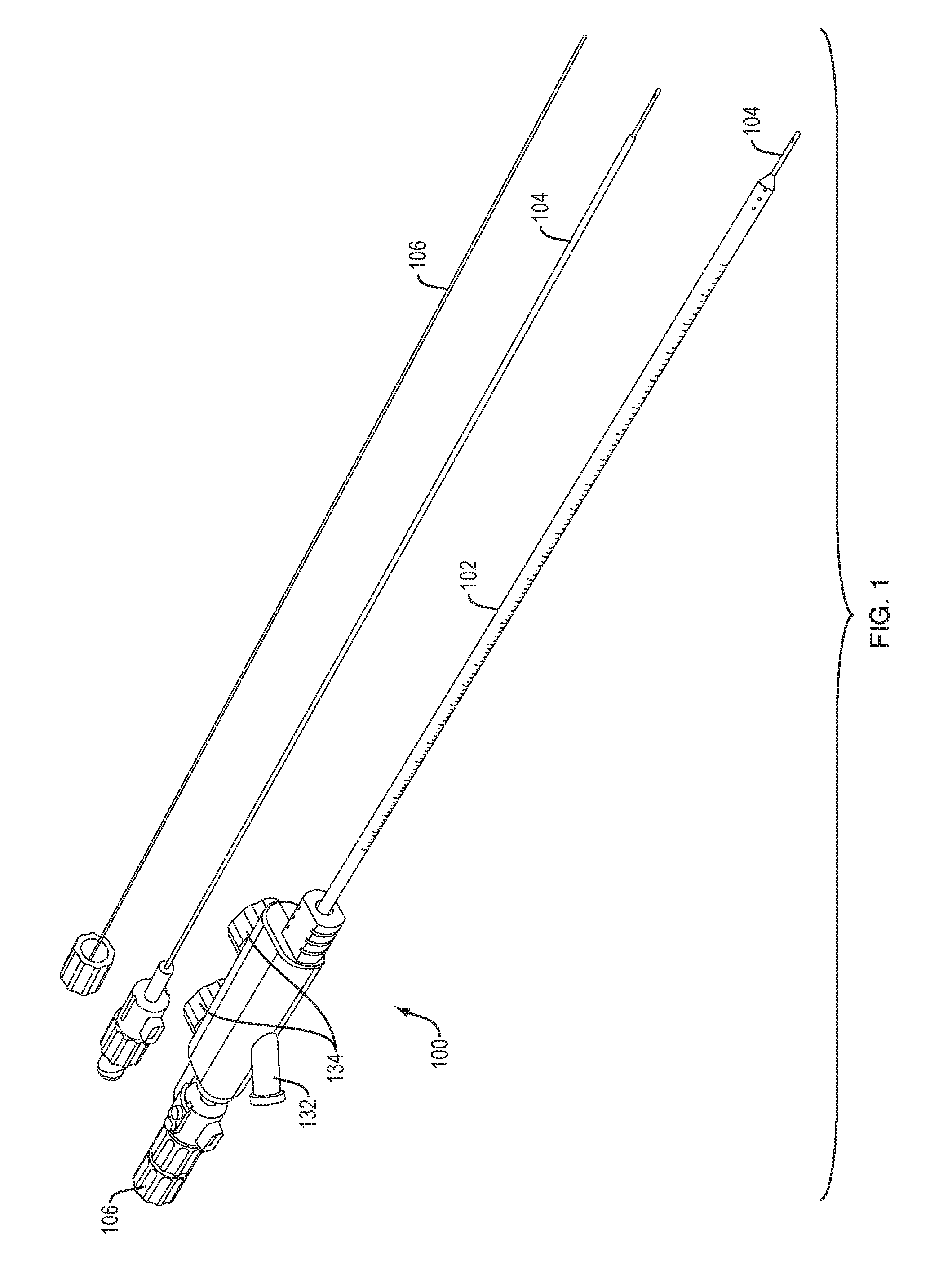
FIG. 1 is a perspective view of an exemplary catheter system, shown in assembled form and with an extra infusion lumen and insertion stylet;
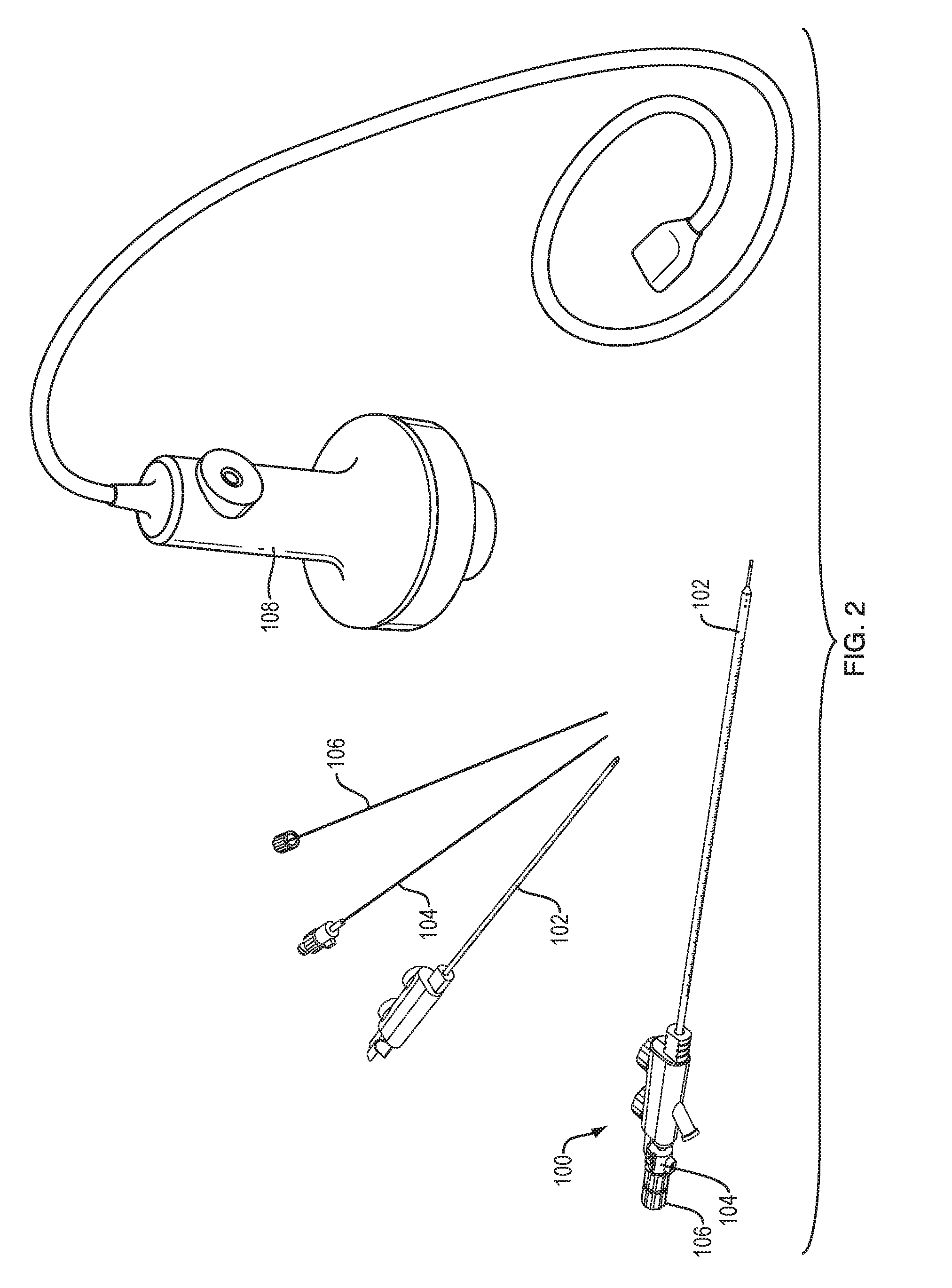
FIG. 2 is a perspective view of the catheter system of FIG. 1, in exploded and assembled configurations and shown with a TRA module;
FIG. 3A is an enlarged perspective view and an enlarged sectional view of the distal end of the catheter system of FIG. 1;
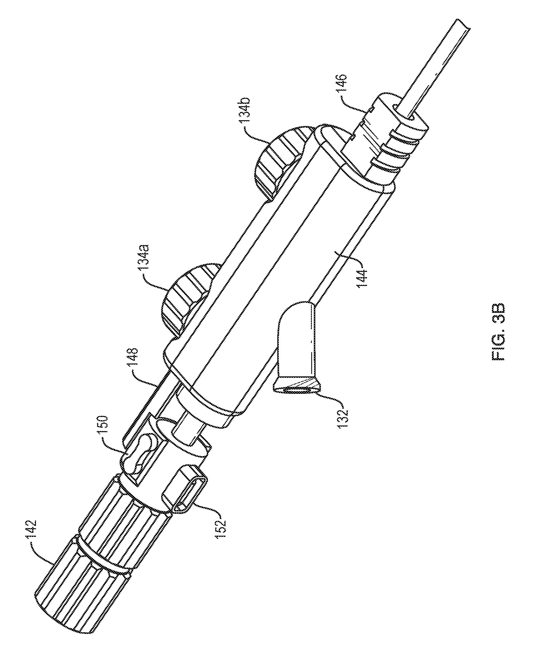
FIG. 3B is an enlarged perspective view of the proximal end of the catheter system of FIG. 1;
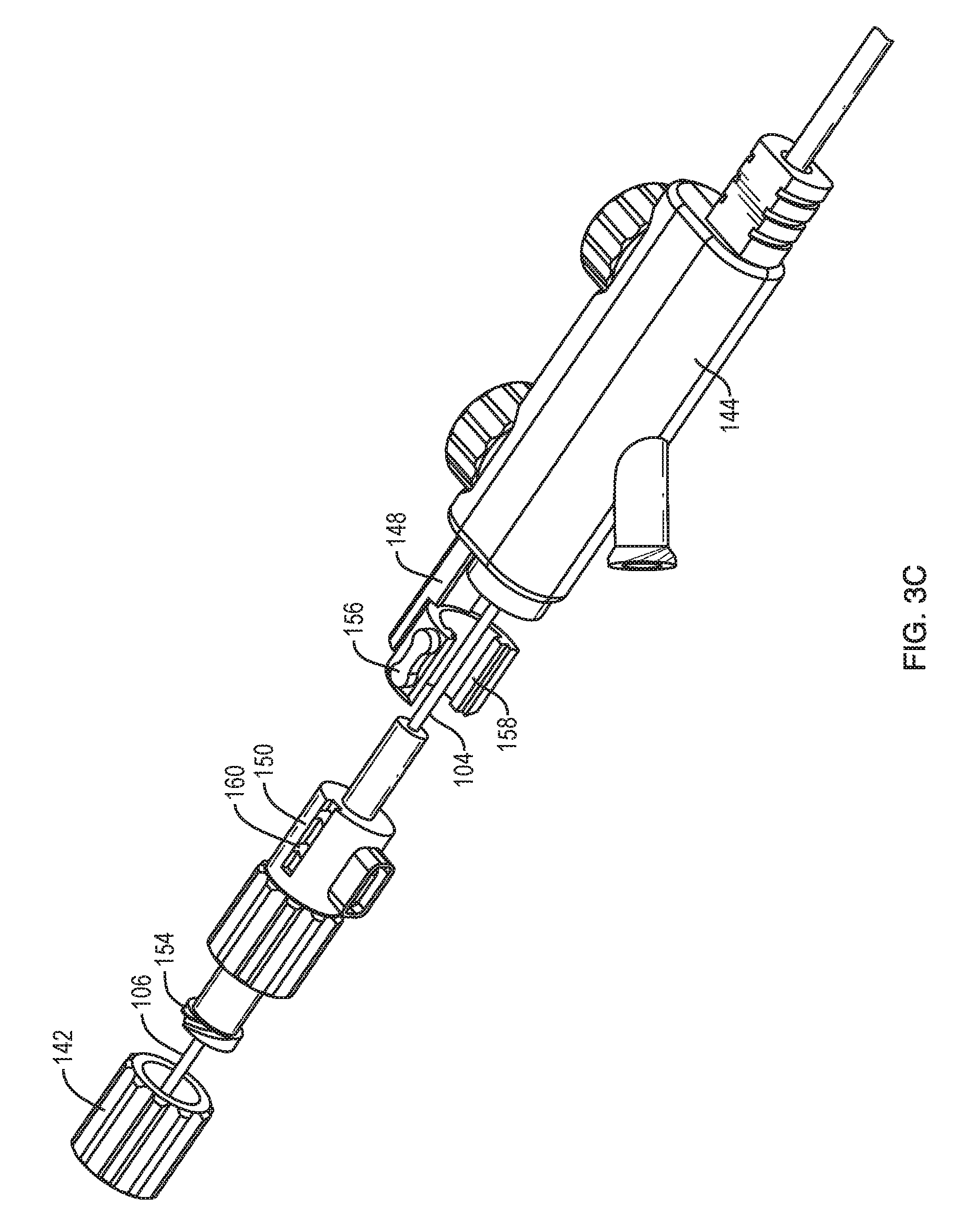
FIG. 3C is an enlarged exploded view of the proximal end of the catheter system of FIG. 1;
FIG. 4A is a schematic view of a clot;
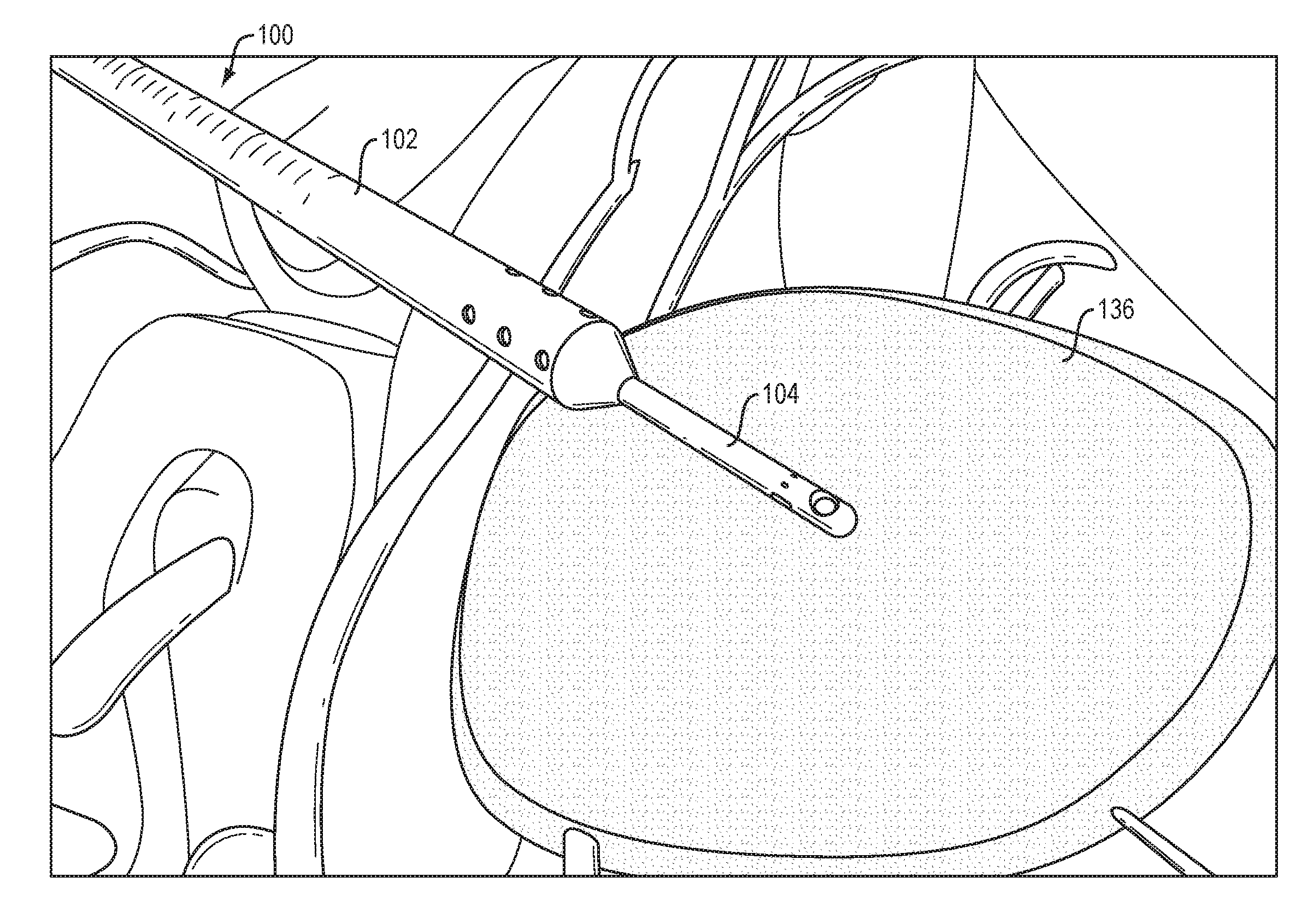
FIG. 4B is a schematic view of the clot of FIG. 4A with the catheter system of FIG. 1 inserted into the clot;
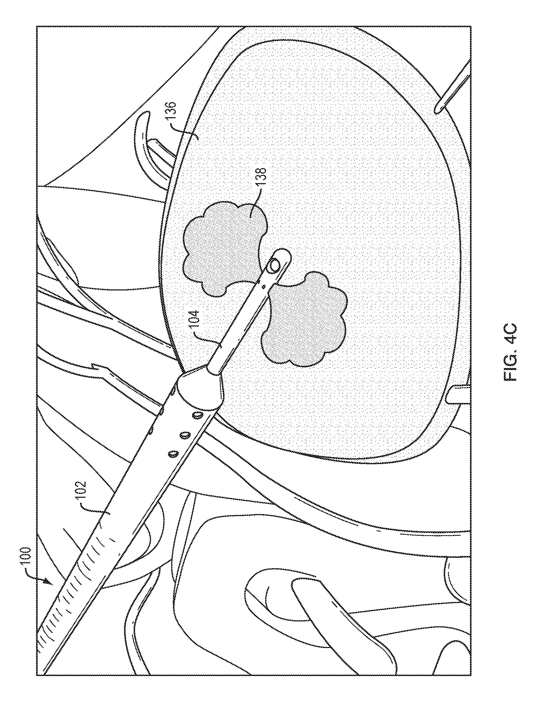
FIG. 4C is a schematic view of the clot of FIG. 4A with the catheter system of FIG. 1 infusing a fluid into the clot;
FIG. 4D is a schematic view of the clot of FIG. 4A with the catheter system of FIG. 1 applying ultrasound energy to the clot;
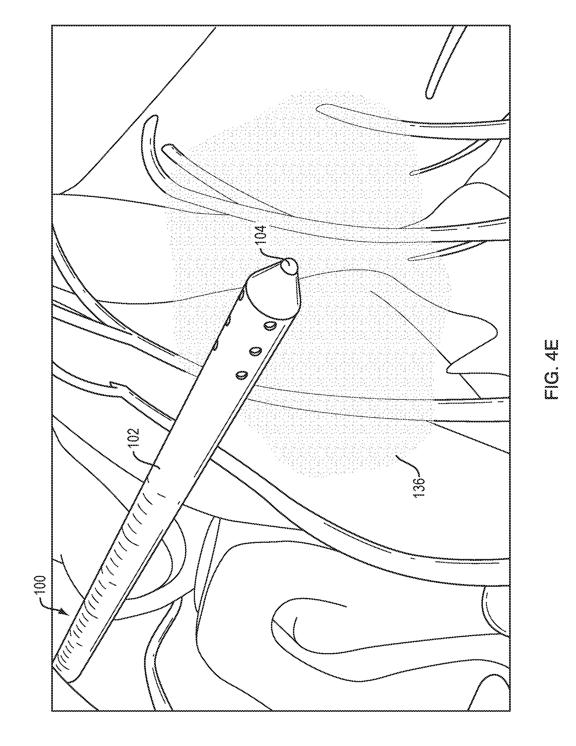
FIG. 4E is a schematic view of the clot of FIG. 4A being aspirated through the catheter system of FIG. 1;
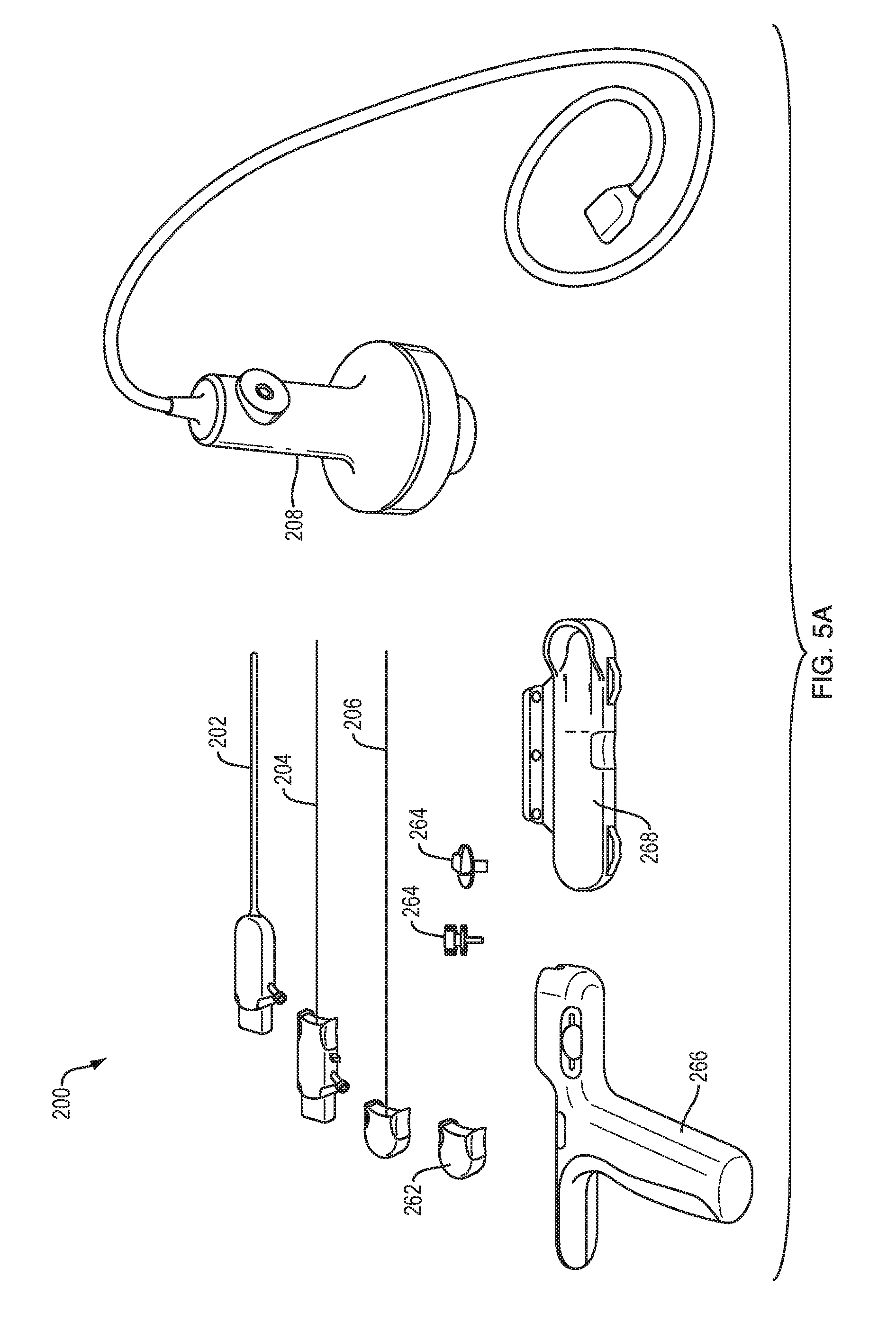
FIG. 5A is a perspective view of an exemplary modular catheter system, shown in a disassembled state and with a TRA module;
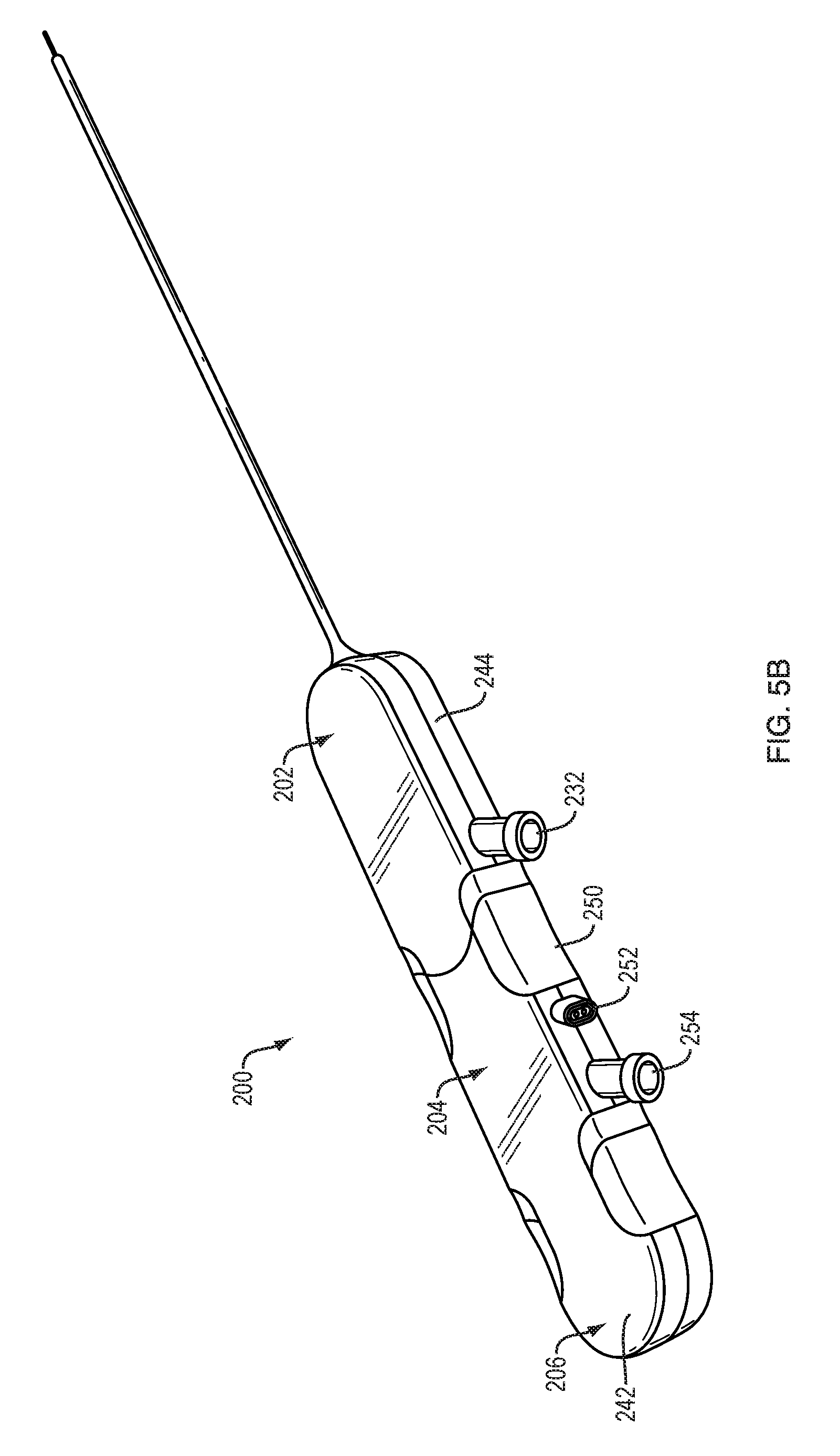
FIG. 5B is a perspective view of the system of FIG. 5A in a first assembly arrangement;
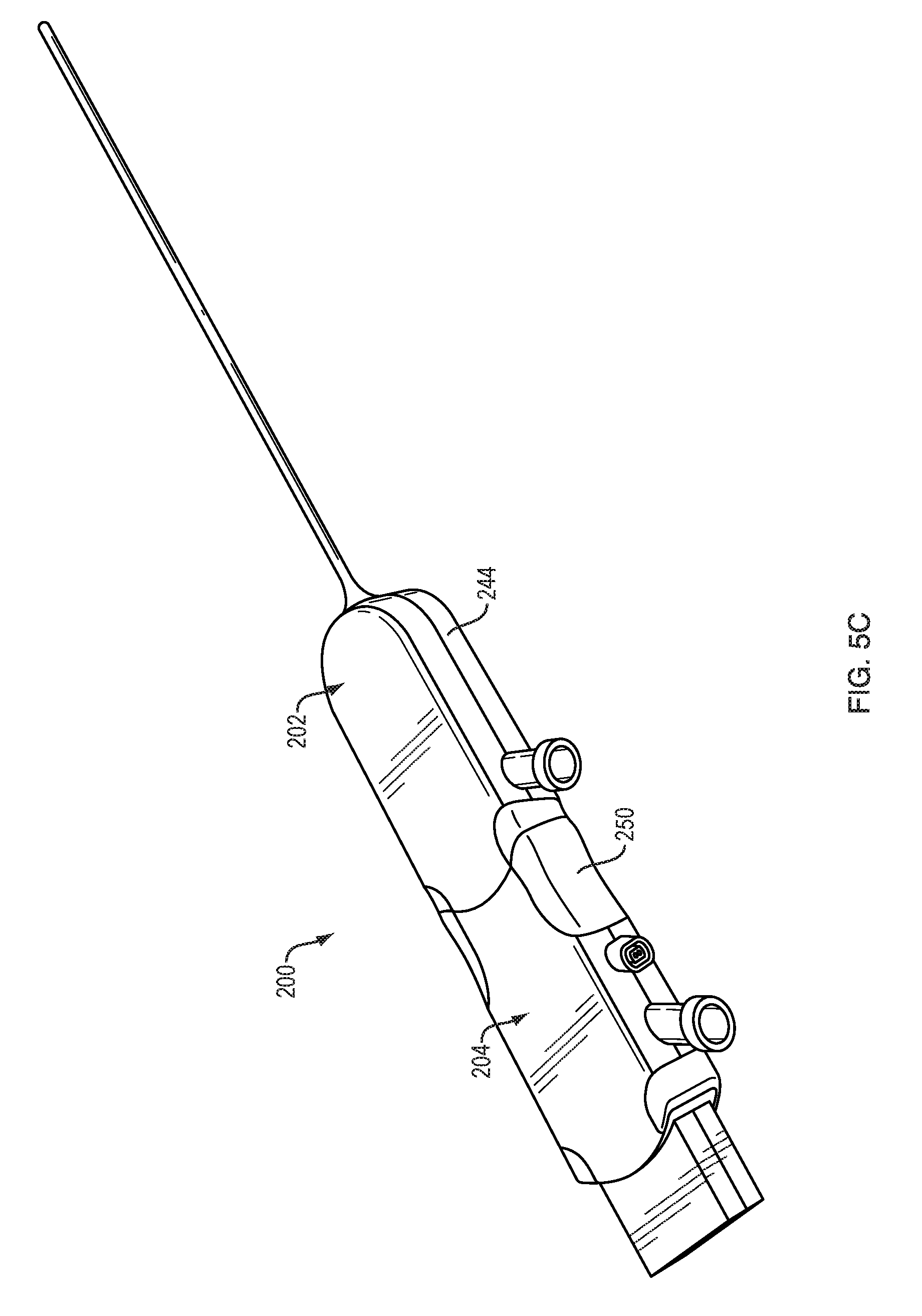
FIG. 5C is a perspective view of the system of FIG. 5A in a second assembly arrangement;
FIG. 5D is a perspective view of the system of FIG. 5A in a third assembly arrangement;
FIG. 5E is a perspective view of a catheter assembly and hand control module of the system of FIG. 5A;
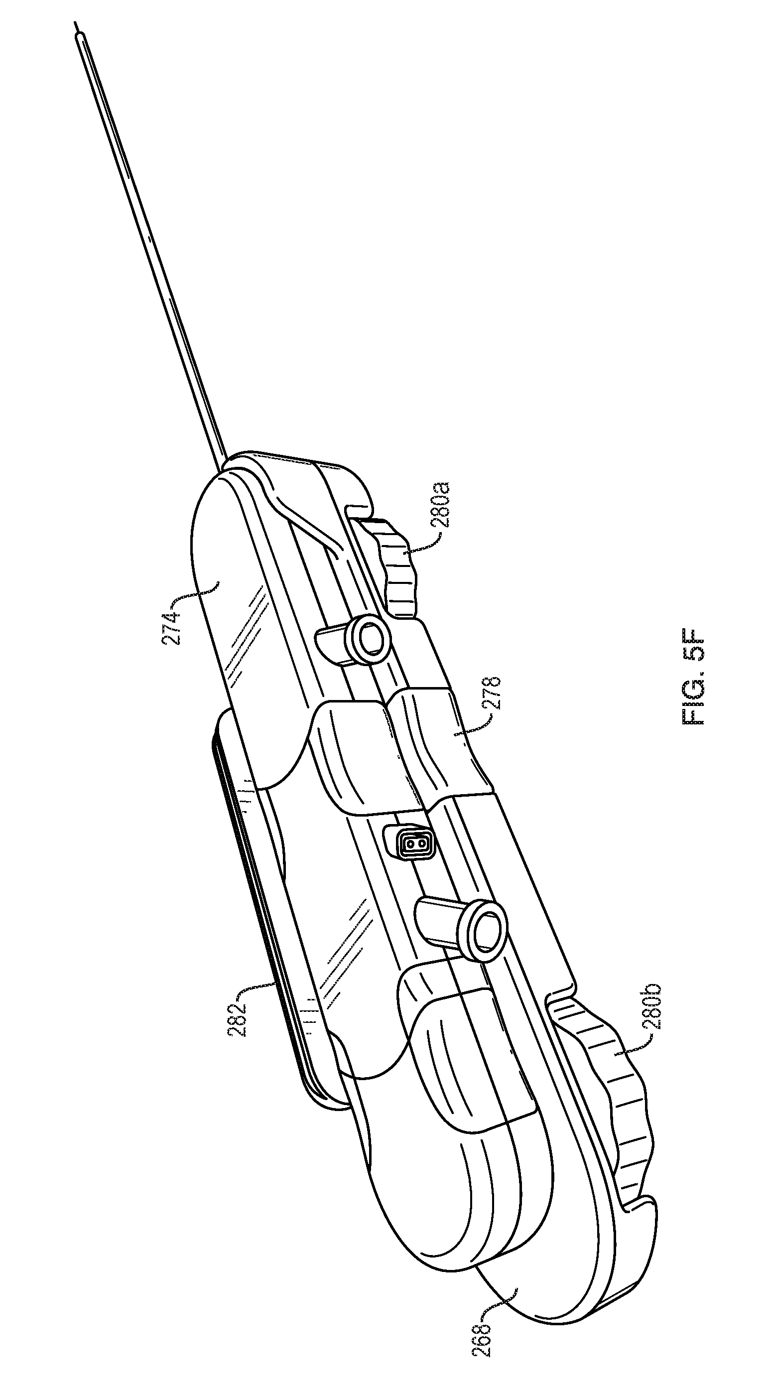
FIG. 5F is a perspective view of a catheter assembly and stereotactic module of the system of FIG. 5A;
FIG. 6A is a schematic view of the system of FIG. 5A being used to treat a patient with a hematoma;
FIG. 6B is a schematic view of the hematoma of FIG. 6A with the catheter system of FIG. 5A inserted into the hematoma;
FIG. 6C is a schematic view of the hematoma of FIG. 6A with the catheter system of FIG. 5A infusing a fluid into the hematoma;
FIG. 6D is a schematic view of the hematoma of FIG. 6A with the catheter system of FIG. 5A applying ultrasound energy to the hematoma; and
FIG. 6E is a schematic view of the hematoma of FIG. 6A being aspirated through the catheter system of FIG. 5A.
DETAILED DESCRIPTION
Methods and devices are disclosed herein that allow for infusion and aspiration through a single device. The device can be used to treat a stroke by delivering the device to the site of a blood clot and simultaneously or sequentially infusing a thrombolytic or other drug into the clot and aspirating the dissolving clot from the patient. The methods and devices can advantageously permit more efficient thrombolytic infusion and clot aspiration. Modular systems are also disclosed, as are methods of treating subdural hematoma or other conditions.
Certain exemplary embodiments will now be described to provide an overall understanding of the principles of the structure, function, manufacture, and use of the systems and methods disclosed herein. One or more examples of these embodiments are illustrated in the accompanying drawings. Those skilled in the art will understand that the systems and methods specifically described herein and illustrated in the accompanying drawings are non-limiting exemplary embodiments. The features illustrated or described in connection with one exemplary embodiment may be combined with the features of other embodiments. Such modifications and variations are intended to be included within the scope of the present disclosure.
FIGS. 1-3C illustrate an exemplary embodiment of a catheter system 100. As shown, the system 100 can include an aspiration catheter 102 and an infusion catheter 104. The system 100 can also include a removable insertion stylet 106.
The system 100 can include a time reversal acoustics (TRA) module 108 or other device for focusing acoustic energy (e.g., ultrasound energy) to enhance or control infusion. In an exemplary TRA system, a hydrophone at the distal end of the catheter measures an acoustic signal at the drug delivery site. The sensed acoustic signal is communicated through a wired or wireless interface to a processor or circuit that time reverses the acoustic signal. The time-reversed acoustic signal is then used to drive a reverberator placed external to the patient. The acoustic energy applied by the reverberator can be used to enhance or quicken the infusion of the drug and/or control the direction in which the drug is infused. Further details on TRA and drug delivery can be found in OLBRICHT, W. et al., TIME-REVERSAL ACOUSTICS AND ULTRASOUND-ASSISTED CONVECTION-ENHANCED DRUG DELIVERY TO THE BRAIN, J Acoust Soc Am. 2013 August; 134(2):1569-75, which is hereby incorporated by reference herein.
As shown in FIG. 2, the insertion stylet 106 can be inserted through a lumen of the infusion catheter 104 and the infusion catheter and stylet can be inserted through a lumen of the aspiration catheter 102.
Referring to FIG. 3A, the infusion catheter 104 can include an elongate tubular body that defines a central fluid lumen 110. The infusion catheter 104 can include one or more fluid outlet ports 112, which can be formed at any of a variety of locations on the catheter. In the illustrated embodiment, the fluid outlet ports 112 are formed in lateral sidewalls of the catheter 104. The catheter 104 can include first and second diametrically opposed side exit fluid outlet ports 112 formed adjacent a distal end thereof. The infusion catheter 104 can include one or more radiopaque markers 114 to facilitate visualization during a surgical procedure, e.g., via fluoroscope, CT, MRI, or PET imaging. A MEMS hydrophone or a micro hydrophone 116 can be disposed adjacent a distal end of the infusion catheter 104 for detecting an acoustic signal for use in the TRA system 108 described above. One or more electrical leads 118 for communicating the detected acoustic signal to a proximal end of the catheter 104 and the other components of the TRA system 108 can be embedded in a sidewall of the infusion catheter 104 or threaded through the central lumen 110 of the catheter.
As also shown in FIG. 3A, the aspiration catheter 102 can include an elongate tubular body that defines a central lumen 120 in which the infusion catheter 104 is disposed. The infusion catheter 104 can be longitudinally-translatable within the central lumen 120 relative to the aspiration catheter 102. The aspiration catheter 102 can include one or more aspiration lumens 122 through which dissolved clots or other material can be extracted from a treatment site. In the illustrated embodiment, the aspiration catheter 102 includes first and second aspiration lumens 122 having C-shaped transverse cross-sections disposed on either side of the central lumen 120. It will be appreciated that the aspiration lumens 122 can have any of a variety of other shapes and configurations. The aspiration lumens 122 can be in fluid communication with an exterior of the aspiration catheter 102 via one or more aspiration ports 124, which can be formed in a lateral sidewall of the aspiration catheter as shown.
The aspiration catheter 102 can include one or more radiopaque markers 126 to facilitate visualization during a surgical procedure. A distal end of the aspiration catheter 102 can have a tapered, ramped, or bulleted shape 128 that provides a gradual transition from the larger external diameter of the aspiration catheter to the smaller external diameter of the infusion catheter 104. This shape can advantageously form a seal with surrounding tissue in which the system 100 is inserted to prevent backflow of infusate along the insertion track of the catheters 102, 104 and thereby substantially contain infused drug to the distal end of the infusion catheter and its general vicinity. The system 100 can include other features for reducing or preventing backflow, such as an overtube that defines a tissue-receiving space configured to pinch tissue and form a seal therewith, for example as disclosed in U.S. Pat. No. 8,992,458 entitled "SYSTEMS AND METHODS FOR REDUCING OR PREVENTING BACKFLOW IN A DELIVERY SYSTEM" which is hereby incorporated by reference herein. Exemplary bullet-nose features are also disclosed in this reference.
The aspiration catheter 102 can include a mechanism for remotely steering the distal end of the catheter within a treatment site. In the illustrated embodiment, the aspiration catheter 102 includes first and second diametrically opposed steering wires 130 embedded in sidewalls of the catheter. Tension can be applied to proximal ends of the steering wires 130 disposed external to the patient to steer the distal end of the catheter 102 within the treatment site.
The aspiration catheter 102 can include an aspiration port 132 through which the catheter can be connected to a vacuum pump or other aspiration source. The system 100 can include various controls 134 for operating the system. For example, as shown in FIGS. 3B-3C, the system can include a first knob 134A configured to control extension and retraction of the infusion catheter 104 relative to the aspiration catheter 102. The first knob 134A can be coupled to a wheel that frictionally engages or otherwise mechanically engages the infusion catheter 104 such that rotation of the knob 134A causes the infusion catheter 104 to translate longitudinally with respect to the aspiration catheter 102. Alternatively, as shown, the first knob 134A can be engaged with a beam 148 slidably mounted to a housing 144 of the aspiration catheter 102. A proximal portion of the beam 148 can be selectively attached to a mounting body 150 of the infusion catheter 104. For example, the beam 148 can include a C-shaped clip 156 configured to fit around the mounting body 150. The clip 156 can include opposed ridges 158 that engage corresponding grooves 160 of the mounting body 150 to releasably retain the clip to the mounting body. The ridges 158 and grooves 160 can be keyed such that relative longitudinal movement between the clip 156 and the mounting body 150 is prevented when the ridges and grooves are mated. It will be appreciated that the ridges and grooves can be interchanged, e.g., such that the grooves are formed in the clip 156 and the ridges are formed in the mounting body 150. Rotation of the first knob 134A can be effective to translate the beam 148, and the mounting body 150 and infusion catheter 104 by extension, longitudinally with respect to the aspiration catheter 102 to advance or retract the infusion catheter relative to the aspiration catheter. The mounting body 150 of the infusion catheter 104 can include a connector 152 for establishing an electric, acoustic, and/or optical connection between the hydrophone 116 and the TRA system 108.
The system 100 can include a second knob 134B configured to control steering of the aspiration catheter 102. The second knob 134B can be rotated to selectively apply tension to the steering wires 130 to steer the aspiration catheter 102. The system can also include controls for selectively and/or individually applying aspiration to the first and second aspiration lumens 122.
The removable insertion stylet 106 shown in FIGS. 1-2 can be selectively positioned within the central lumen 110 of the infusion catheter 104 to facilitate insertion and targeting of the catheter system 100. The stylet 106 can include an attachment cap 142 at a proximal end thereof. The cap 142 can facilitate grasping of the stylet 106 by a user and can be used to attach the stylet to the infusion catheter 104 or the aspiration catheter 102, e.g., via a threaded or snap-fit coupling formed around or adjacent to a proximal infusion port 154 of the infusion catheter.
A proximal end of the aspiration catheter 102 can include a body or housing 144. The housing 144 can include a mounting block 146 to facilitate attachment of the housing to a stereotactic frame.
FIGS. 4A-4E illustrate an exemplary method of using the system 100 to deliver a drug to a patient and remove a clot from the patient, e.g., to treat stroke.
As shown in FIG. 4A, the site of a clot or hemorrhage 136 can be located within the patient (e.g., within the patient's brain) and a stereotactic approach to the site can be planned.
The catheter system 100 can then be guided to the site 136, e.g., using stereotactic navigation, as shown in FIG. 4B. Once at the site, or at any other desired time, the insertion stylet 106 can be removed from the catheter system 100.
As shown in FIG. 4C, a drug 138 can be infused through the infusion catheter 104 to the target site 136. The term "drug" as used herein refers to any functional agent that can be delivered to a human or animal patient, including hormones, stem cells, gene therapies, chemicals, compounds, small and large molecules, dyes, antibodies, viruses, therapeutic agents, etc. The drug can be or can include a thrombolytic agent (e.g., tPA). Alternatively, or in addition, an irrigation fluid such as saline can be delivered through the infusion catheter 104.
As the drug 138 is infused through the infusion catheter 104, the TRA module 108 can be actuated to deliver focused acoustic energy 140 to the target site 136 and thereby rapidly diffuse the drug 138 throughout the clot and/or control the direction of drug diffusion, as shown in FIG. 4D.
As shown in FIG. 4E, the aspiration catheter 102 can be advanced distally over the infusion catheter 104 and into the clot 136 to aspirate the clot material as it dissolves. The distal end of the aspiration catheter 102 can be steered within the treatment site 136 to ensure that all of the clot material is aspirated. For example, the steering wires 130 of the aspiration catheter 120 can be actuated to sweep the catheter tip back and forth within the treatment site 136. Irrigation fluid can be delivered to the treatment site 136 to flush out the clot material. Once the clot is removed, or at any other desired time, the system 100 can be removed from the patient. As discussed below, one or more components of the system, e.g., the aspiration catheter 102, can be left in place for long-term drainage over a period of hours, days, or weeks.
In some embodiments, one or more components of the system can be modular. A modular catheter system can accommodate various different workflows. For example, a stylet, infusion, and aspiration assembly can be used to place the catheter, the stylet can then be removed and the end capped for infusion/irrigation and TRA ultrasound, then the infusion module can be removed, leaving a compact drain module for longer term drainage where necessary or desirable.
FIGS. 5A-5F illustrate an exemplary modular catheter system 200. Except as described herein and as will be readily appreciated by one having ordinary skill in the art, the catheter system 200 of FIGS. 5A-5F can be substantially similar to the catheter system 100 described above. Accordingly, a detailed description of the structure and function of the catheter system of FIGS. 5A-5F is omitted here for the sake of brevity.
Referring to FIG. 5A, the system 200 can include an aspiration catheter 202 and an infusion catheter 204. The system 200 can include a stylet 206 insertable through the catheters 202, 204 to facilitate insertion of the system into a patient. The system 200 can include a cap 262 to cap off a proximal end of the system, e.g., when the stylet 206 or infusion catheter 204 is removed. The system can include one or more skull anchors or catheter guides 264 for securing the system to a patient or for guiding the catheter. The system 200 can include a hand control module 266 to provide single-handed, ambidextrous operation of the system controls, providing for efficient hand-guided procedures. The system 200 can include a low-profile stereotactic module 268 to provide controls in a compact platform for integration into stereotactic navigation systems. The system 200 can include a TRA module 208 or other device for focusing acoustic energy (e.g., ultrasound energy) to enhance or control infusion.
As shown, the coaxial stylet 206, infusion catheter 204, and aspiration catheter 202 can be substantially the same as in the system 100. In the system 200, however, each catheter's proximal end terminates in a modular cartridge housing that allows for different combinations of the functional elements of the system based on the demands of a given treatment. For example, the system 200 can allow a user to leave the aspiration catheter in place for continued drainage after an initial treatment procedure. The modular cartridge housings can take a variety of forms. The illustrated embodiment shows a flattened rounded rectangular shape, but other shapes such as cylindrical designs can be used instead or in addition.
In the extended drainage scenario, once the initial infusion of thrombolytic and TRA ultrasound dispersal is completed, or at any other desired time, the infusion catheter 204 can be completely removed, and the proximal end of the aspiration catheter 202 capped, e.g., using the cap 262, so that the aspiration catheter can remain in place. When capped, the proximal end can be more compact than the full catheter system, further facilitating extended implantation. Additionally, the central bore of the aspiration catheter 202 can provide an additional drainage path in this configuration.
The system 200 can include removable hand and/or stereotactic controls, which can further facilitate extended implantation. Packaging the controls on a removable module can allow the modular "cartridge" to be as compact as possible, and can also allow the various catheter functions (e.g., steerability and infusion catheter advance/retract) to be locked when the controls are removed. This can prevent accidental actuation of any of these functions during extended implantation.
FIG. 5B illustrates a first arrangement of the system 200, in which the stylet 206 is inserted through the infusion catheter 204, which is inserted through the aspiration catheter 202. A proximal stylet cap or housing 242 can be positioned adjacent to a proximal infusion catheter housing 250 which can be positioned adjacent to a proximal aspiration catheter housing 244. The housings 242, 250, 244 can be modular cartridges that can be selectively mated to one another, e.g., via a snap-fit or other connection. The aspiration catheter housing 244 can include an aspiration port 232. The infusion catheter housing 250 can include an infusion port 254. The infusion catheter housing 250 can include a connector 252 for the TRA system 208. The arrangement of FIG. 5B can be used for initial placement of the system 200 within a patient.
FIG. 5C illustrates a second arrangement of the system 200, which can be identical to the first arrangement except that the stylet 206 is removed. The stylet housing 242 can be replaced with the cap 262. The arrangement of FIG. 5C can be used for aspiration and/or infusion.
FIG. 5D illustrates a third arrangement of the system 200, which can be identical to the second arrangement except that the infusion catheter 204 is removed. The infusion catheter housing 250 can be replaced with the cap 262. The arrangement of FIG. 5D can be used for aspiration, e.g., as a compact drain assembly for long-term drainage. This arrangement can also be used for infusion, e.g., by infusing fluid through the aspiration lumen of the aspiration catheter 202.
FIG. 5E illustrates the system 200 in a configuration in which the modular cartridges of the catheter assembly (e.g., one or more of the stylet 206, the infusion catheter 204, and the aspiration catheter 202) are coupled to a hand control module 266. The hand control module 266 can provide single-handed, ambidextrous operation of the system controls, providing for efficient hand-guided procedures. The hand control module 266 can include an ergonomic handle 270, e.g., a pistol-grip handle, a pencil-type handle, etc. The hand control module 266 can include a release button 272 that can be actuated to release the catheter assembly 274 from the hand control module 266. The hand control module 266 can include one or more controls 276 for controlling operation of the catheter assembly 274. For example, the hand control module 266 can include sliding levers, rotating knobs, pushable buttons, or other control features for advancing or retracting the infusion catheter 204 relative to the aspiration catheter 202, or for steering one or both of the catheters 202, 204. The controls 276 can operate in a manner similar to that of the knobs 134A, 134B described above.
FIG. 5F illustrates the system 200 in a configuration in which the modular cartridges of the catheter assembly (e.g., one or more of the stylet 206, the infusion catheter 204, and the aspiration catheter 202) are coupled to a low-profile stereotactic module 268. The stereotactic module 268 can provide controls in a compact platform for integration into stereotactic navigation systems. The stereotactic module 268 can include a release button 278 that can be actuated to release the catheter assembly 274 from the stereotactic module 268. The stereotactic module 268 can include one or more controls 280 for controlling operation of the catheter assembly 274. For example, the stereotactic module 268 can include sliding levers, rotating knobs, pushable buttons, or other control features for advancing or retracting the infusion catheter 204 relative to the aspiration catheter 202, or for steering one or both of the catheters 202, 204. The controls 280 can operate in a manner similar to that of the knobs 134A, 134B described above. In the illustrated embodiment, the stereotactic module 268 includes a forward control knob 280A for steering the aspiration catheter 202 and a rearward control knob 280B for advancing or retracting the infusion catheter 204 relative to the aspiration catheter 202. The stereotactic module 268 can include an attachment feature configured to attach the system 200 to a stereotactic frame or guidance system. For example, as shown, the stereotactic module 268 can include a dovetail mounting block 282 for integration into a stereotactic system.
FIGS. 6A-6E illustrate an exemplary method of using a catheter system, e.g., the system 100 or the system 200 disclosed herein, to treat a hematoma, such as a subdural hematoma.
As shown in FIG. 6A, the site of the hematoma 284 can be accessed, for example by performing a twist drill craniostomy over the hematoma location. A skull anchor 264 can be installed and the catheter system 200 can be fed through the skull anchor into the subdural space.
Steering functionality can be used to guide the distal end of the catheter system 200 into position within the hematoma 284, as shown in FIG. 6B.
As shown in FIG. 6C, the infusion/irrigation catheter 204 can be extended distally from the aspiration catheter 202 and into the hematoma 284. Irrigation and/or infusion of a thrombolytic or other drug 286 can be performed through the catheter 204.
Focused ultrasound 288 can be applied to the hematoma 284 as shown in FIG. 6D, e.g., using a TRA system 208, to diffuse irrigation fluid and/or a drug and to break up the hematoma.
As shown in FIG. 6E, the infusion catheter 204 can be retracted and/or the aspiration catheter 202 can be advanced to aspirate the hematoma. Steering functionality can be used to target areas in need of aspiration.
While use in procedures to remove clots from the brain for treatment of stroke is generally contemplated herein, it will be appreciated that the methods and devices herein can be used for any of a variety of other medical or non-medical procedures. For example, the methods and devices herein can be used to dissolve and/or remove any type of tissue from any location within a human or animal patient, and can be used to treat various conditions other than stroke.
It should be noted that any ordering of method steps expressed or implied in the description above or in the accompanying drawings is not to be construed as limiting the disclosed methods to performing the steps in that order. Rather, the various steps of each of the methods disclosed herein can be performed in any of a variety of sequences. In addition, as the described methods are merely exemplary embodiments, various other methods that include additional steps or include fewer steps are also within the scope of the present disclosure.
Although the invention has been described by reference to specific embodiments, it should be understood that numerous changes may be made within the spirit and scope of the inventive concepts described. Accordingly, it is intended that the invention not be limited to the described embodiments.
* * * * *
D00000
D00001
D00002
D00003
D00004
D00005
D00006
D00007
D00008
D00009
D00010
D00011
D00012
D00013
D00014

D00015

D00016
D00017

D00018

D00019

D00020

D00021

XML
uspto.report is an independent third-party trademark research tool that is not affiliated, endorsed, or sponsored by the United States Patent and Trademark Office (USPTO) or any other governmental organization. The information provided by uspto.report is based on publicly available data at the time of writing and is intended for informational purposes only.
While we strive to provide accurate and up-to-date information, we do not guarantee the accuracy, completeness, reliability, or suitability of the information displayed on this site. The use of this site is at your own risk. Any reliance you place on such information is therefore strictly at your own risk.
All official trademark data, including owner information, should be verified by visiting the official USPTO website at www.uspto.gov. This site is not intended to replace professional legal advice and should not be used as a substitute for consulting with a legal professional who is knowledgeable about trademark law.