Adjustable applicator
Kukreja Ja
U.S. patent number 10,531,722 [Application Number 15/897,482] was granted by the patent office on 2020-01-14 for adjustable applicator. This patent grant is currently assigned to HCT PACKAGING, INC.. The grantee listed for this patent is HCT PACKAGING, INC.. Invention is credited to Shipra Kukreja.


| United States Patent | 10,531,722 |
| Kukreja | January 14, 2020 |
Adjustable applicator
Abstract
An adjustable applicator including an application member and an actuator. The application member comprises a flexible support and a plurality of application elements on its surface. The application member has one free end and one fixed end. The fixed end is fixedly connected to a stem. The free end of the application member is connected to a distal end of the transmission member. The actuator is actuated for moving the transmission member along a longitudinal axis of the adjustable applicator to cause progressive modification in shape of the application member.
| Inventors: | Kukreja; Shipra (New Delhi, IN) | ||||||||||
|---|---|---|---|---|---|---|---|---|---|---|---|
| Applicant: |
|
||||||||||
| Assignee: | HCT PACKAGING, INC.
(Bridgewater, NJ) |
||||||||||
| Family ID: | 63105956 | ||||||||||
| Appl. No.: | 15/897,482 | ||||||||||
| Filed: | February 15, 2018 |
Prior Publication Data
| Document Identifier | Publication Date | |
|---|---|---|
| US 20180228270 A1 | Aug 16, 2018 | |
Foreign Application Priority Data
| Feb 16, 2017 [IN] | 201711005605 | |||
| Current U.S. Class: | 1/1 |
| Current CPC Class: | A46B 5/0033 (20130101); A46B 9/021 (20130101); A46B 15/0095 (20130101); A46B 7/023 (20130101); A45D 40/265 (20130101); A45D 2200/10 (20130101) |
| Current International Class: | A45D 40/26 (20060101); A46B 9/02 (20060101); A46B 7/02 (20060101); A46B 5/00 (20060101); A46B 15/00 (20060101) |
References Cited [Referenced By]
U.S. Patent Documents
| 715881 | December 1902 | Scott |
| 783937 | February 1905 | Edwards et al. |
| 987277 | March 1911 | Wright |
| 1030440 | June 1912 | Jvaterman |
| 1065879 | June 1913 | Krebs |
| 1067596 | July 1913 | Fesler |
| 1112193 | September 1914 | Carleton et al. |
| 1142698 | June 1915 | Grove et al. |
| 1170923 | February 1916 | Malkin |
| 1185617 | June 1916 | Blaha et al. |
| 1188214 | June 1916 | Sohn |
| 1190227 | July 1916 | Fesler |
| D51319 | October 1917 | Montgomery |
| 1261502 | April 1918 | Farrows |
| 1274697 | August 1918 | Dynowsky |
| 1355026 | October 1920 | Austin |
| 1358597 | November 1920 | Tobias |
| 1429823 | September 1922 | Allison |
| 1457615 | June 1923 | Bunker |
| 1506292 | August 1924 | Corsello |
| 1510898 | October 1924 | Nikicser |
| 1563031 | November 1925 | Jones |
| 1626992 | May 1927 | Willk |
| 1639388 | August 1927 | Stebbings |
| 1651355 | December 1927 | Alland |
| 1659800 | February 1928 | Bailey |
| 1831393 | November 1931 | Pierce, Jr. |
| 1889496 | November 1932 | Priest |
| 2104651 | January 1938 | Hoffman, Jr. |
| 2132943 | October 1938 | Frazier |
| D134797 | January 1943 | Lubkin |
| 2321265 | June 1943 | Ulvick |
| 2442051 | May 1948 | Luscri |
| 2485822 | October 1949 | Goldrich |
| 2591537 | April 1952 | Gordon |
| 2637060 | May 1953 | Cowan |
| 2637868 | May 1953 | Hamilton |
| 2697642 | December 1954 | Rudy |
| 2701378 | February 1955 | Reinbolt et al. |
| 2736051 | February 1956 | Boodakian |
| 2825080 | March 1958 | Bongiovanni |
| 2866993 | January 1959 | Edelstone |
| 2874399 | February 1959 | Solomon |
| 2946072 | July 1960 | Filler et al. |
| 2982983 | May 1961 | Peterson |
| 3007188 | November 1961 | Dolan |
| 3106738 | October 1963 | Bohne |
| 3193863 | July 1965 | Myers et al. |
| 3205523 | September 1965 | Seaver |
| D204449 | April 1966 | Zavodsky |
| 3309728 | March 1967 | Seaver |
| 3592202 | July 1971 | Jones |
| 3863288 | February 1975 | Aversa |
| 3908676 | September 1975 | Levine et al. |
| D245462 | August 1977 | Hauf |
| 4088413 | May 1978 | Rossignol de la Ronde et al. |
| D249600 | September 1978 | Bowman |
| 4129918 | December 1978 | Lee et al. |
| 4165755 | August 1979 | Cassai |
| 4204294 | May 1980 | Halverson |
| D258241 | February 1981 | Takada et al. |
| 4248543 | February 1981 | Carrington et al. |
| 4428388 | January 1984 | Cassai et al. |
| 4446880 | May 1984 | Gueret |
| 4483036 | November 1984 | Sayklay |
| 4502497 | March 1985 | Siahou et al. |
| D278951 | May 1985 | Kalinsky |
| 4545393 | October 1985 | Gueret |
| 4600328 | July 1986 | Clements |
| 4727618 | March 1988 | Mahoney et al. |
| D297889 | October 1988 | Ries et al. |
| 4869612 | September 1989 | Mooney |
| 4898193 | February 1990 | Gueret et al. |
| 4906120 | March 1990 | Sekiguchi et al. |
| 4917132 | April 1990 | Tuchman |
| 4927281 | May 1990 | Gueret et al. |
| D310917 | October 1990 | Futter |
| 5063947 | November 1991 | Gueret et al. |
| 5137038 | August 1992 | Kingsford et al. |
| 5153066 | October 1992 | Tanaka et al. |
| 5165760 | November 1992 | Gueret et al. |
| 5211494 | May 1993 | Baijnath et al. |
| 5220702 | June 1993 | Howell et al. |
| 5301695 | April 1994 | Wong |
| 5328282 | July 1994 | Charrier et al. |
| 5339483 | August 1994 | Byun et al. |
| 5388599 | February 1995 | Yen et al. |
| D362965 | October 1995 | Tastanis |
| 5482059 | January 1996 | Miraglia |
| 5491865 | February 1996 | Gueret |
| 5507063 | April 1996 | Hirsch |
| 5535474 | July 1996 | Salazar |
| 5588447 | December 1996 | Gueret |
| 5596785 | January 1997 | Park |
| D380615 | July 1997 | Roberts |
| 5690441 | November 1997 | McManus |
| 5778479 | July 1998 | Raia |
| 5802658 | September 1998 | Ward |
| 5960745 | October 1999 | Boyland |
| 5992423 | November 1999 | Tevolini |
| 6026824 | February 2000 | Gueret |
| D421846 | March 2000 | Choe |
| 6039051 | March 2000 | Dorf |
| D425794 | May 2000 | Grossnickle |
| 6059474 | May 2000 | Huang |
| 6070597 | June 2000 | Motherhead |
| D434187 | November 2000 | Schoon et al. |
| 6145151 | November 2000 | Herron et al. |
| 6145514 | November 2000 | Clay et al. |
| 6158443 | December 2000 | Leman et al. |
| 6164857 | December 2000 | Wolfarth-Brooks et al. |
| D439415 | March 2001 | Mink et al. |
| D442369 | May 2001 | Damiano |
| 6224287 | May 2001 | Gieux |
| 6226828 | May 2001 | Lin |
| 6234181 | May 2001 | Lou |
| 6269515 | August 2001 | Varma |
| D448178 | September 2001 | Tapley et al. |
| 6298863 | October 2001 | Byun |
| 6309125 | October 2001 | Peters |
| D450189 | November 2001 | Mink et al. |
| D450930 | November 2001 | Mink et al. |
| D450931 | November 2001 | Mink et al. |
| 6311358 | November 2001 | Soetewey et al. |
| 6312182 | November 2001 | Dumler |
| D451681 | December 2001 | Mink et al. |
| D454001 | March 2002 | Mink et al. |
| 6363948 | April 2002 | Choi |
| 6401290 | June 2002 | Barton et al. |
| 6405402 | June 2002 | Choi |
| 6418939 | July 2002 | Byun |
| 6438784 | August 2002 | Yu |
| D471018 | March 2003 | Mink |
| D479917 | September 2003 | Mink |
| D479918 | September 2003 | Mink |
| D480218 | October 2003 | Mink |
| 6669389 | December 2003 | Gueret |
| D485442 | January 2004 | Twigg |
| 6832405 | December 2004 | Miller |
| 6880197 | April 2005 | Katz et al. |
| 6898818 | May 2005 | Lin |
| D506069 | June 2005 | Woods |
| 6935802 | August 2005 | Byun |
| 6957468 | October 2005 | Driesen et al. |
| 6974513 | December 2005 | Kepka |
| 7096598 | August 2006 | Myatt |
| D527529 | September 2006 | Ajluni et al. |
| D528305 | September 2006 | Langer |
| 7101107 | September 2006 | Byun |
| 7107645 | September 2006 | Bressler et al. |
| 7111354 | September 2006 | Nennig et al. |
| D529292 | October 2006 | Langer |
| 7127770 | October 2006 | Clegg et al. |
| 7159950 | January 2007 | Young-Chul |
| 7201527 | April 2007 | Thorpe et al. |
| 7234474 | June 2007 | Byun |
| 7275885 | October 2007 | Byun |
| D562005 | February 2008 | King |
| D562566 | February 2008 | Mink |
| 7344327 | March 2008 | Gueret |
| D566969 | April 2008 | Sherman et al. |
| D568050 | May 2008 | Huang |
| D571105 | June 2008 | Godin |
| 7429141 | September 2008 | Habatjou |
| 7465113 | December 2008 | Gueret |
| D584897 | January 2009 | Belley |
| D601804 | October 2009 | Hwang |
| 7653960 | February 2010 | Lee |
| D612615 | March 2010 | Chitayat et al. |
| 7716775 | May 2010 | DiPietro et al. |
| D626338 | November 2010 | Ajootian |
| 7866758 | January 2011 | Jang |
| D631666 | February 2011 | Lim |
| D632488 | February 2011 | Twigg |
| 7895696 | March 2011 | Belmonte |
| 7895698 | March 2011 | Mink |
| 7918620 | April 2011 | Del Ponte |
| 7950402 | May 2011 | Cole |
| 7996947 | August 2011 | Gueret |
| 8074666 | December 2011 | Piao |
| D651409 | January 2012 | Papenfu |
| 8104132 | January 2012 | Mink |
| 8117707 | February 2012 | Ruh, II |
| 8132285 | March 2012 | Piao |
| 8132541 | March 2012 | Baer, Jr. |
| 8141561 | March 2012 | Thorpe et al. |
| D658385 | May 2012 | Lim et al. |
| D658389 | May 2012 | Salgatar |
| 8185998 | May 2012 | Xu |
| 8220469 | July 2012 | Spagnuolo |
| 8230543 | July 2012 | Shrier et al. |
| 8251074 | August 2012 | Pires et al. |
| 8256058 | September 2012 | Telwar |
| 8307836 | November 2012 | Pires et al. |
| 8321987 | December 2012 | Bagley |
| 8360078 | January 2013 | Lim et al. |
| D677059 | March 2013 | Floyd |
| D677060 | March 2013 | Floyd |
| D677470 | March 2013 | Floyd |
| 8402592 | March 2013 | Byrne et al. |
| D681342 | May 2013 | Brower |
| 8850652 | October 2014 | Lim |
| D717548 | November 2014 | Lim |
| 8881745 | November 2014 | Pires et al. |
| 8899243 | December 2014 | Pires et al. |
| D725912 | April 2015 | Sims et al. |
| D730062 | May 2015 | Lim |
| D739148 | September 2015 | Lim |
| D767903 | October 2016 | Lim |
| D778069 | February 2017 | Lim |
| 10098438 | October 2018 | Pires |
| 2002/0078902 | June 2002 | Ehrmann |
| 2002/0148058 | October 2002 | Greenwood et al. |
| 2003/0005533 | January 2003 | Woodnorth et al. |
| 2003/0035953 | February 2003 | Weihrauch |
| 2003/0066151 | April 2003 | Chang |
| 2003/0110585 | June 2003 | Rechelbacher |
| 2004/0134009 | July 2004 | Sander et al. |
| 2004/0168700 | September 2004 | Dorf |
| 2005/0011030 | January 2005 | Gonzalez |
| 2005/0031401 | February 2005 | Gueret |
| 2005/0198759 | September 2005 | Segrea |
| 2005/0273962 | December 2005 | Dillon |
| 2006/0026783 | February 2006 | McKay |
| 2006/0150355 | July 2006 | Mason et al. |
| 2006/0162736 | July 2006 | Gray |
| 2006/0254012 | November 2006 | Konishi |
| 2006/0272668 | December 2006 | Wyatt et al. |
| 2007/0034224 | February 2007 | Dumler |
| 2007/0124882 | June 2007 | Lee |
| 2007/0151061 | July 2007 | Mink et al. |
| 2007/0199575 | August 2007 | Del Ponte |
| 2007/0289602 | December 2007 | Simmons |
| 2007/0295351 | December 2007 | Germer |
| 2008/0060668 | March 2008 | Legassie |
| 2008/0256733 | October 2008 | Brown |
| 2008/0276396 | November 2008 | Lucero |
| 2009/0014022 | January 2009 | Salciarini |
| 2009/0041530 | February 2009 | Deans |
| 2009/0089949 | April 2009 | Mink et al. |
| 2009/0119863 | May 2009 | Gallegos |
| 2009/0183328 | July 2009 | King |
| 2009/0260172 | October 2009 | Weiss |
| 2010/0000566 | January 2010 | Wyatt et al. |
| 2010/0017990 | January 2010 | Piao |
| 2010/0037407 | February 2010 | Telwar |
| 2010/0043815 | February 2010 | Levy et al. |
| 2010/0059080 | March 2010 | Gueret |
| 2010/0200013 | August 2010 | Kim |
| 2010/0212682 | August 2010 | Pires et al. |
| 2010/0224208 | September 2010 | Thorpe et al. |
| 2010/0236004 | September 2010 | Xu |
| 2011/0056505 | March 2011 | Parkinson et al. |
| 2011/0083690 | April 2011 | Cardenas et al. |
| 2012/0017930 | January 2012 | Nance |
| 2012/0167910 | July 2012 | Weigel |
| 2012/0260931 | October 2012 | Martin et al. |
| 2012/0272982 | November 2012 | Telwar et al. |
| 2012/0298130 | November 2012 | Telwar |
| 2013/0017010 | January 2013 | Liu |
| 2013/0111683 | May 2013 | Lim et al. |
| 2014/0216497 | August 2014 | Gueret |
| 2014/0259489 | September 2014 | Dale |
| 2014/0325775 | November 2014 | Nakamura et al. |
| 2014/0331422 | November 2014 | Lim |
| 2014/0332027 | November 2014 | Lim |
| 2015/0010340 | January 2015 | Pires et al. |
| 2017/0265626 | September 2017 | Earl et al. |
| 2018/0055205 | March 2018 | Pires |
| 2018/0177281 | June 2018 | Pires |
| 2018/0255908 | September 2018 | Wightman |
| 1196212 | Oct 1998 | CN | |||
| 201734124 | Feb 2011 | CN | |||
| 201734141 | Feb 2011 | CN | |||
| 201929278 | Aug 2011 | CN | |||
| 302655796 | Nov 2013 | CN | |||
| 302667633 | Dec 2013 | CN | |||
| 303098564 | Feb 2015 | CN | |||
| 29713124 | Sep 1997 | DE | |||
| 2084986 | Aug 2009 | EP | |||
| 2464674 | Mar 1981 | FR | |||
| 2642283 | Aug 1990 | FR | |||
| 2976463 | Dec 2012 | FR | |||
| 2003033228 | Feb 2003 | JP | |||
| 2003135140 | May 2003 | JP | |||
| 1218834 | Oct 2004 | JP | |||
| 1343552 | Nov 2008 | JP | |||
| 2009172300 | Aug 2009 | JP | |||
| 300365471 | Oct 2004 | KR | |||
| 300404554 | Dec 2004 | KR | |||
| 300607863 | Aug 2011 | KR | |||
| 1020130025549 | Mar 2013 | KR | |||
| 101257563 | May 2013 | KR | |||
| 200472950 | May 2013 | KR | |||
| 9211785 | Jul 1992 | WO | |||
| 2006034815 | Apr 2006 | WO | |||
| 2007117091 | Oct 2007 | WO | |||
| 2010098997 | Sep 2010 | WO | |||
| 2016177827 | Nov 2016 | WO | |||
| 2018152182 | Aug 2018 | WO | |||
| 2018152185 | Aug 2018 | WO | |||
| 2018152191 | Aug 2018 | WO | |||
Other References
|
All for One, Full Magnetic Travel Brush Set, Sephora, retrieved on Feb. 26, 2015 at <>, 3 pages. cited by applicant . CN 3417893 Registered Design, (Tianjin Samsun Brushes Ltd.) Jan. 12, 2005, [online], [retrieved on Oct. 3, 2014] Retrieved from the Questel Intellectual Property Portal Design Database using the Internet: <URL: http://www.orbit.com. cited by applicant . Dual Interchangeable Brush Set, Global Market, retrieved on Mar. 18, 2015 at <>, 2 pages. cited by applicant . Everbluec Singapore Beauty Makeup and Skincare Blog, May 14, 2011 [online], Elizabeth Arden makeup blender, [retrieved on Mar. 14, 2015] Retrieved from the Internet: http://everbluec.com/2011/05/ceramide-colors-exclusive-launch-at.html>- -. cited by applicant . Fingermax Creative Finger Painting Paint Brush, retrieved on Oct. 9, 2014 at http://thesotre.com/fingermax-creative-finger-painting-paint-br- ush/TSHVY6X6YF , 5 Pages. cited by applicant . Givenchy Demesure Audacious Lashes Mascara, May 17, 2011, retrieved from the internet at <>, 9 pages. cited by applicant . Lady Zona, "Choosing the Right Make Up Brush", Retrieved on Feb. 24, 2015 at <&- gt;, 3 pages. cited by applicant . Latest design double end kabuki blush brush, Alibaba.com, retrieved on Mar. 18, 2015 at <>, 3 pages. cited by applicant . Launch Pad Mojo Magpro Professional Magnetic Brush Set, Beauty and the Blog, retrieved on Feb. 26, 2015 at http://www.beautyandblog.com/2012/01/Iaunch-pad-mojo-magpro-profe- ssional.html, 4 pages. cited by applicant . LeKeux, "My Cosmetic Range" LeKeux HQ, retrieved on Feb. 24, 2015 at <&- gt;, 6 Pages. cited by applicant . Makeup Brushes Buying Guide, Ebay, Jun. 9, 2014, retrieved on Mar. 18, 2015 at <>, 6 pages. cited by applicant . Popcorn Yubi-fude Finger Brush, Japan Trend Shop, retrieved on Oct. 8, 2014 at <>, 3 pages. cited by applicant . Why Didn't We Think of That: Magnetic Makeup Brush, Gloss Daily, retrieved on Feb. 26, 2015 at <>, 2 pages. cited by applicant . International Search Report and Written Opinion dated May 25, 2018 for International Application No. PCT/US2018/018158. cited by applicant . International Search Report and Written Opinion dated May 25, 2018 for International Application No. PCT/US2018/018167. cited by applicant . International Search Report and Written Opinion dated May 25, 2018 for International Application No. PCT/US2018/018153. cited by applicant. |
Primary Examiner: Walczak; David J
Assistant Examiner: Gruby; Randall A
Attorney, Agent or Firm: Seager, Tufte & Wickhem LLP
Claims
What is claimed is:
1. An adjustable applicator for applying a product to a surface, the adjustable applicator comprising: a cap having a dialer and a sleeve, the dialer rotatably coupled to the sleeve; a stem having an upper portion coupled to the sleeve, the stem having a cavity therein; a transmission member having an upper end coupled to the dialer, at least a portion of the transmission member slidingly disposed with the cavity of the stem; a flexible application member including a plurality of application elements extending from at least a portion of an outer surface thereof, the application member comprising a first end fixedly coupled to a lower end of the stem and a second end coupled to a lower end of the transmission member; wherein rotation of the dialer relative to the sleeve in a first direction initiates a progressive modification of a shape of the application member between at least a first configuration and a second configuration; wherein when in the first configuration, the transmission member is in an extended position thereby holding the second end of the application member spaced apart from the lower end of the stem, and when in the second configuration, the transmission member is in a retracted position thereby holding the second end of the application member in contact with the lower end of the stem.
2. The adjustable applicator of claim 1, wherein rotation of the dialer relative to the sleeve in the first direction initiates an incremental modification of the shape of the application member between the first and second configurations.
3. The adjustable applicator of claim 1, wherein when in the first configuration, a first portion of the application member extends linearly from the lower end of the stem.
4. The adjustable applicator of claim 1, wherein rotation of the dialer relative to the sleeve in a second direction opposite the first direction initiates a progressive modification of the shape of the application member between the second configuration and the first configuration.
5. The adjustable applicator of claim 1, wherein the plurality of application elements extend from only a portion of an inner surface of the application member, wherein when in the first configuration, a first portion of the inner surface of the application member faces the transmission member and is devoid of application elements.
6. The adjustable applicator of claim 1, wherein the application member has a rectangular shape with the plurality of application elements extending from less than all sides thereof.
7. An adjustable applicator for applying a product to a surface, the adjustable applicator comprising: a cap, the cap having an upper portion and a lower portion; a stem having an upper portion coupled to the lower portion of the cap, the stem having a cavity therein; an application member having a first end coupled to a lower end of the stem; and a transmission member having an upper end coupled to the upper portion of the cap and a lower end coupled to a second end of the application member, the transmission member slidingly disposed within the cavity of the stem; wherein the upper portion of the cap comprises an actuator which is actuatable to initiate a progressive modification the application member from a first configuration, in which the application member has a J shape, to a second configuration in which the application member has a closed loop shape, with a plurality of configurations therebetween.
8. The adjustable applicator of claim 7, wherein the actuator is actuatable to initiate a progressive modification of the application member from the second configuration back to the first configuration.
9. The adjustable applicator of claim 7, wherein the application member includes a plurality of application elements extending outward therefrom, wherein when in the first configuration, a first portion of an outer surface of the application member faces the transmission member and is devoid of application elements.
Description
CROSS REFERENCE TO RELATED PATENT APPLICATIONS
The present application claims the benefit of and priority to Indian Patent Application Serial Number 201711005605, filed on Feb. 16, 2017, the disclosure of which is incorporated herein by reference.
TECHNICAL FIELD
Embodiments of the present disclosure relate to an adjustable applicator for applying a cosmetic or personal care composition, e.g. mascara to eyelashes or eyebrows. More particularly, the disclosure, relates to an applicator that can be adjusted as per a user's convenience for application of a cosmetic or a care product.
BACKGROUND
Mascara, an important make-up accessory used to darken and define eyelashes to accentuate the eyes, is difficult to apply because of the target area of application. The eyelashes offer a very small application area, while being soft, flexible, delicate and in close proximity to very sensitive eye tissue. Therefore, a mascara product would be liked by the consumers when a right kind of applicator is provided to them for easy application as the overall consumer experience depends on both the product and on the applicator used to apply it.
Conventional mascara brushes are in the form of a generally cylindrical straight rod carrying a plurality of bristles extending radially outwardly from its outer surface. However, straight mascara brushes are not thought by some people to be ideal for all purposes and curved mascara brushes are also known.
One applicator may be generally straight and have short, densely arrayed bristles and may be employed for applying mascara to eyelashes to achieve a desired effect (e.g. to volumize eyelashes). While another applicator may incorporate a bend and have longer, less densely arrayed bristles for applying mascara to eyelashes to achieve an alternative desired effect (e.g., to separate and define eyelashes).
Curved mascara brushes permit contact of the brush with more eyelashes along a correspondingly curved eyelid. However, the curved brush is more difficult to use in the confines of the eye area, particularly the corners of the eye where a straight brush works better. Another drawback of a pre-curved brush is that it is not readily adjustable to confirm to a particular user's eyelid curvature. In addition, the curvature of the upper and lower eyelids is rarely the same and a brush curved to fit the upper lid will not properly fit the lower lid.
Adjustable mascara brushes are known in the prior art. It is known to provide adjustment of the angle of the brush or applicator relative to the applicator wand or handle.
Thus, existing applicators have limited functionality and are not conducive to applying mascara to eyelashes using different techniques and/or different orientations. Accordingly, there remains a need in the art for improved applicator systems that allow application of mascara using different techniques and/or orientations to achieve multiple desired effects.
Therefore, there exists a need for an applicator that provides ease-of-use as well as is modifiable to adapt to the shape requirement of the user.
SUMMARY
The present disclosure generally is an adjustable applicator employed for application of a cosmetic or a care product such as for application of mascara, coloring strands of hair, for dental flossing or for applying pharmaceuticals or cleaning agents. The use of adjustable applicator of the present disclosure for removal of make-up products is also contemplated.
According to an embodiment of the present disclosure, there is provided an adjustable applicator including an application member that can be adjusted as per user's convenience for application of a cosmetic or a care product.
In accordance with an embodiment of the disclosure, the adjustable applicator extends along a longitudinal axis and comprises of an applicator head comprising an application member; a stem and a cap; wherein the applicator head is connected at a distal end of the stem and the cap is connected at a proximal end of the stem.
In accordance with an embodiment of the disclosure, the adjustable applicator includes an actuator formed by an upper portion of the cap, which when actuated initiates a mechanism for progressive modification in the shape of the applicator head.
According to an embodiment, the actuator is a dialer but in other alternate embodiments, the dialer can be replaced by other actuator such as a slider, a push button and the like which can actuate using manual, mechanical, magnetic, electrical or any other suitable force.
According to an embodiment of the disclosure, the adjustable applicator includes a transmission member having a distal end and a proximal end. The distal end of the transmission member is connected at an end of the applicator head and the proximal end of the transmission member is connected to a dialer of the adjustable applicator.
The actuator is actuated for moving the transmission member along the longitudinal axis to cause progressive modification in shape of the application member.
According to an embodiment of the disclosure, the applicator head comprises an application member and a shank for attaching the applicator head to a distal end of the stem. The application member comprises a flexible support and a plurality of application elements on its surface. The application member has one free end and one fixed end. The fixed end is fixedly connected to the shank. The free end of the application member is connected to a distal end of the transmission member. The application member is flexible as well as elastic in nature. Thus, the application member is capable of changing its shape on application of force because it is flexible in nature and since it is also elastic in nature, it is capable of returning to original shape after removal of force.
According to an embodiment of the disclosure, the application elements are in form of tines molded integrally with the flexible support. However, it would not be beyond the scope of the present disclosure, if the application elements are in form of flocking of fibers, sponge, metal or any other material known in the art.
According to an embodiment of the disclosure, the application elements are present on a surface of the flexible support which faces away from the transmission member. Further, the application elements are present on a portion of a circumference/perimeter of the flexible support and not on the complete circumference/perimeter of the flexible support. However, it would not be beyond the scope of present disclosure, if the application elements are present on a complete circumference/perimeter of a cross-section of the flexible support.
According to an embodiment of the disclosure, the flexible support has a non-circular shape. However, the flexible support may have a shape selected from circular, oval, polygonal, rectangular shape etc.
When the dialer is rotated, the application member can adopt at least two stable configurations including a first configuration in which the transmission member is moved to its maximum extent towards proximal direction and a second configuration in which the transmission member is moved to its maximum extent towards a distal direction.
In the first configuration, the application member has a straight or linear shape whereas in the second configuration, the application member has a curved shape. Further, in the first configuration, the application elements are present only on one side of the transmission member whereas in the second configuration, the application elements are present on two sides of the transmission member.
Still further, in the first configuration, a distal end of the applicator head is formed by a distal most portion of the application member whereas in the second configuration, the distal end of the applicator head is formed by substantially middle portion of the application member. Also, in the first configuration, the applicator head has a curved tip and in the second configuration, the applicator head has a curved tip of radius greater than a radius of the curved tip of the first configuration.
More specifically, in the first configuration, the application member has a J-shape whereas in the second configuration, the application member has a closed loop shape. In the first configuration, the application member has a J-shape. In the first configuration, the flexible support of the application member comprises of a single arm extending from the shank and a curved tip. The curved tip is formed in continuation of the single arm such that a concave side of the curved tip faces towards the distal end of the stem.
In the second configuration, the application member has a closed loop-shape. In the second configuration, the flexible support of the application member comprises two arms and a curved tip formed between the two arms. One end of each of the two arms is in contact with the shank. The two arms together with the curved tip forms a cavity.
Independently or in combination with the above, exemplary embodiments of the disclosure provide a cosmetic package for packaging and dispensing a substance, for example, a cosmetic, comprising an adjustable applicator as defined above. The device may comprise a receptacle and the adjustable applicator. The adjustable applicator in such a device may comprise a cap, a stem having a cavity, an applicator head having an application member and a shank; and a transmission member extending between the applicator head and the cap. The stem may be connected to the applicator head at one end and to the cap at another end. The said device may also include a wiper member. An upper portion of the cap may form an actuator for adjusting the shape of the applicator head and a lower portion of the cap may form a sleeve for closing the receptacle. The actuator is connected to a proximal end of the transmission member in such a way that rotational movement of the transmission member with respect to the actuator is restricted while translational movement is allowed and the transmission member is non-rotatably connected at its distal end to a distal end of the application member of the applicator head.
According to an embodiment, a distal end of the transmission member is fixedly connected in a groove/cavity (not visible) at the free end of the application member and extends outside the flexible support towards the proximal direction of the stem and into the cavity of the stem and the dialer. Alternately, the transmission member may pass through a channel in the flexible support and may or may not be visible outside the flexible support.
According to an embodiment, the dialer is structured in a closed-end cylindrical shape. The dialer further includes an internal annular skirt projecting from an inner surface of a top wall of the dialer and the internal annular skirt extends towards the receptacle. The internal annular skirt has a small outer diameter, and an annular groove is provided on an outer peripheral surface of the internal annular skirt for attaching the dialer to the sleeve of the cap. The sleeve of the cap is attached with the dialer such that the sleeve is free to rotate relative to the dialer via a snap-fit system comprising the external annular groove and a complementary annular protruding portion of the sleeve. The dialer can thus be turned by the user relative to the sleeve. Further, the inner surface of the internal annular skirt includes an inner profile, such as mating threads capable of interacting with an outer thread of the transmission member mounted axially inside the dialer.
According to an embodiment, for engaging the stem to the sleeve of the cap, an upper tubular portion of the stem has a protruding portion on its outer surface which engages with a complementary groove present on inner surface of the sleeve. On the interfaces where the stem is joined to the sleeve of the cap, the stem and the sleeve of the cap both may have complementary longitudinal protrusions and positioning longitudinal grooves that engage with each other for non-rotatably locking the stem and the sleeve together. However, it is not beyond ambit of the present disclosure that any other non-rotatable engagement known in the art may be employed for locking any relative rotation between the stem and the sleeve.
According to an embodiment, the stem comprises the upper tubular portion, a downward skirt and an elongated hollow shaft. The threads are provided on the inner peripheral surface of the downward skirt of the stem to attach the cap to an externally threaded neck of the container. With the cap so attached, the applicator head is immersed in the product to be applied. The elongated hollow shaft extends beyond the neck in the receptacle. Preferably, the elongated hollow shaft of the stem is disposed around at least a portion of the transmission member so that the transmission member is longitudinally movable with respect to the shaft. In the embodiment illustrated, the shaft and the transmission member have circular transverse cross-sections. Other embodiments may have non-circular transverse cross-sections.
According to an embodiment, the stem further includes such features that allow an axial movement of the transmission member but rotation of the transmission member is prevented when the dialer is rotated with respect to the sleeve. For example, the transmission member includes two annular flanges having two opposing slide cut-outs for receiving corresponding longitudinal guide protrusions of the stem. Further, one or more annular ribs and sealing O-rings are configured around the transmission member so that the transmission member interfaces tightly against an inner wall of the shaft. The annular ribs and the sealing O-rings prevent the product from leaking and ensure steady, smooth, and noiseless extension of the transmission member along the shaft.
The adjustable applicator is in the first configuration in the closed position of the cosmetic package and after being removed from the container of the cosmetic the package. In an open position of the cosmetic package, when the dialer is rotated with respect to the sleeve, the transmission member moves longitudinally with respect to the shaft which cause variation in the profile of the application member as explained above. When a suitable adjustment of the profile of the application member has been made it will be retained while the application member is used. The adjustment is retained until the user intentionally rotates the dialer and the sleeve with respect to each other once again to achieve a different adjustment.
In order to transform the profile of the application member to a second configuration, the dialer is twisted in first direction and the rotational movement of the dialer is converted into translational movement of the transmission member by the rotational movement of the threads within the inner skirt of the dialer. Therefore, the transmission member is now able to retract towards the proximal end of the dialer pulling the free end of the application member towards the distal end of the shaft. As the transmission member is retracted to its maximum extent towards the proximal end of the dialer, the free end of the application member contacts the shank at the distal end of the shaft forming a loop shape having two arms and a curved tip and the application member is transformed to a second configuration. The transmission member can be adjusted to various relative longitudinal positions with respect to the shaft depending on degree of twisting, such that as adjustment is made, profile of the application member varies. Once the adjustment is made, it will be retained without any action by the user, until further adjustment is desired and intentionally made.
Further, the user can rotate the dialer in opposite direction to extend the transmission member towards the distal end of the shaft. As the transmission member is extended towards the distal end of the shaft, the free end is pushed in the distal direction of the applicator so that it moves away from the shank and the loop starts opening up so that the cavity disappears. As the transmission member is extended to its maximum extent towards the distal end, the application member is transformed again to the first configuration so that the application member has only one arm.
The material suitable for forming the application member could be any elastomeric polymer, nylon, sponge, metal etc. which possess both flexibility and elasticity. The materials suitable for forming the receptacle could be polypropylene while the dialer, the sleeve, the transmission member and the stem could be formed of acrylonitrile butadiene styrene or any other suitable polymeric material. The material of the transmission member could be any polymeric material like nylon, TPE, PP or could be a suitable metal. The stem may be formed of polyacetal or any other suitable polymeric material. The material for forming the wiper could be low-density polyethylene. The aforementioned materials for forming various parts of the package of the present disclosure are an example, however other suitable materials may also be used.
The above and other objects, features and advantages of the present disclosure will become clear from the following description of the preferred embodiments when the same is read in conjunction with the accompanying drawings.
BRIEF DESCRIPTION OF THE DRAWINGS
So that the manner in which the above recited features of the present disclosure can be understood in detail, a more particular description of the disclosure, briefly summarized above, may be had by reference to embodiments, some of which are illustrated in the appended drawings. It is to be noted, however, that the appended drawings illustrate only typical embodiments of this disclosure and are therefore not to be considered limiting of its scope, for the disclosure may admit to other equally effective embodiments.
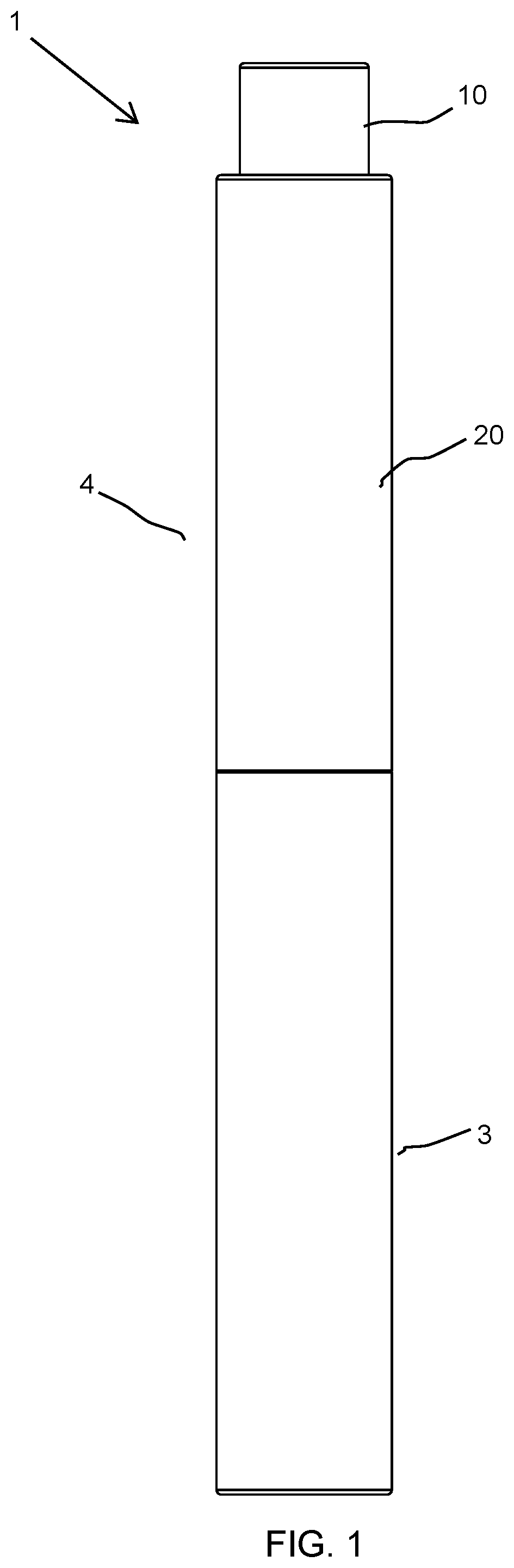
FIG. 1 illustrates a front view of a cosmetic package in closed position according to an embodiment of the present disclosure;
FIG. 2 illustrates a cross sectional view of the cosmetic package of FIG. 1;
FIG. 3 illustrates exploded view of the cosmetic package of FIG. 1;
FIG. 4 illustrates a front view of a first configuration of an adjustable applicator of the cosmetic package of FIG. 1 after being removed from a container of the cosmetic package;
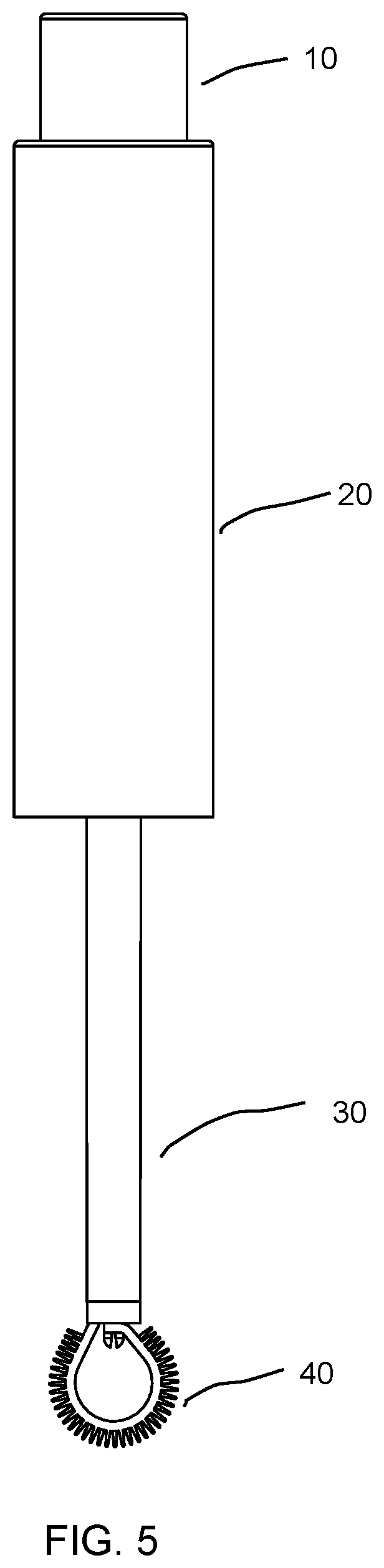
FIG. 5 illustrates front view of a second configuration of an adjustable applicator of the cosmetic package of FIG. 1;
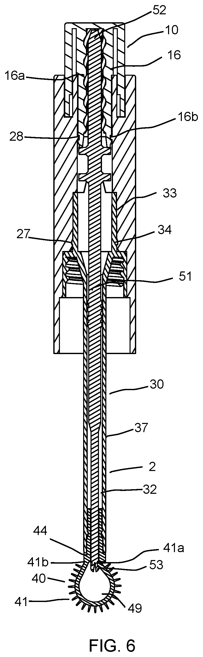
FIG. 6 illustrates a cross sectional view of the second configuration of the adjustable applicator shown in FIG. 5;
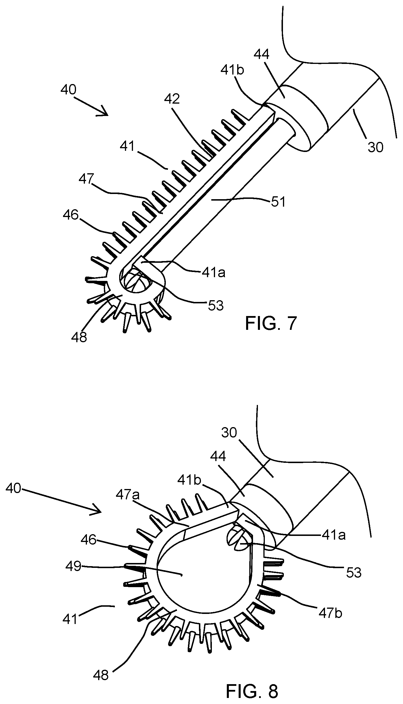
FIG. 7 illustrates enlarged perspective view of the first configuration of the adjustable applicator shown in FIG. 4;
FIG. 8 illustrates enlarged perspective view of the second configuration of the adjustable applicator shown in FIG. 5;
To facilitate understanding, identical reference numerals have been used, where possible, to designate identical elements that are common to the figures. It is to be noted, however, that the appended drawings illustrate only typical embodiments of this disclosure and are therefore not to be considered limiting of its scope, for the disclosure may admit to other equally effective embodiments.
DETAILED DESCRIPTION
FIGS. 1 to 8 show a cosmetic package 1 in accordance with the present disclosure. The cosmetic package 1 includes an application member 41 which can be adjusted as per user's convenience for application of a product including a cosmetic or a care product.
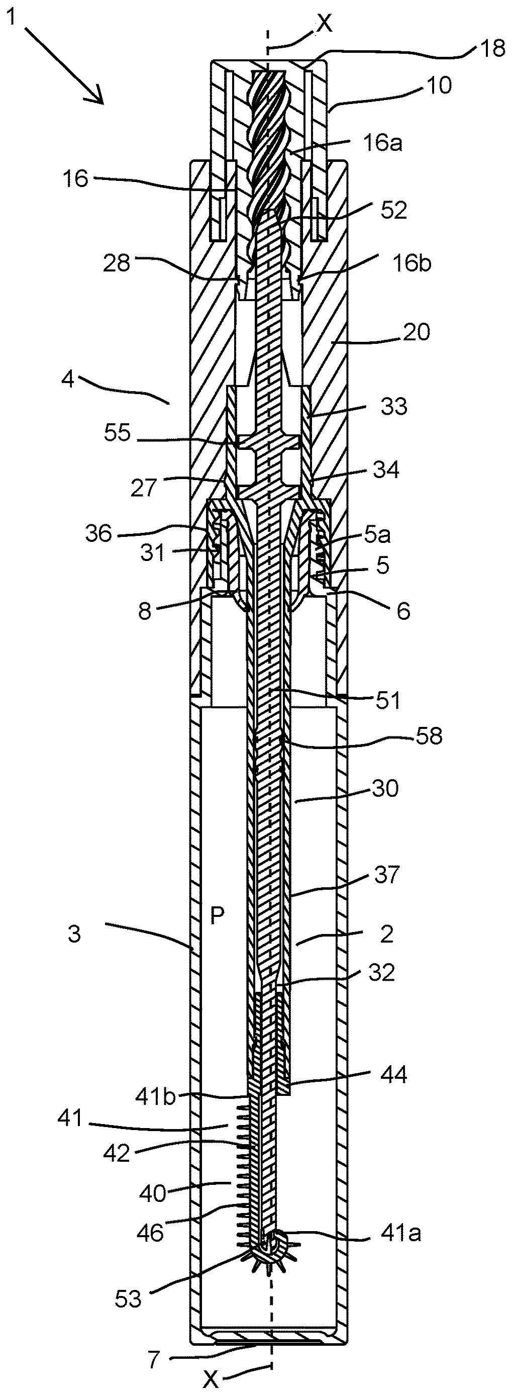
FIGS. 1 and 2 show a cosmetic package 1 in accordance with the present disclosure, in a closed position. The cosmetic package 1 having a longitudinal axis X-X, comprises an adjustable applicator 2 and a receptacle 3. The receptacle 3 and the adjustable applicator 2 are intended to be fastened to each other by screwing. Alternatively, other methods of fastening the receptacle 3 and the adjustable applicator 2 can be used. The receptacle 3 includes a neck 5 extending along the longitudinal axis X-X, a shoulder 6 and an end wall 7 forming a reservoir for a product P.
The adjustable applicator 2 includes a cap 4 suitable for closing the receptacle 3, the applicator head 40 comprising the application member 41 and a stem 30 having a cavity 32. The stem 30 may be connected to the applicator head 40 at one end and to the cap 4 at another end. The applicator head 40 is secured to the stem 30 and intended for being inserted in said receptacle 3 in order to be loaded with the product P to be applied.
The neck 5 of the receptacle 3 is provided with an external thread 5a intended for cooperating with a complementary thread 31 carried by the stem 30, allowing the receptacle 3 to be closed by screwing.
For some cosmetic products, such as mascara or a lip gloss, it is preferable to provide a wiper 8 positioned into the neck 5 of the receptacle 3 to wipe excess product P from the adjustable applicator 2 as the adjustable applicator 2 is withdrawn from the receptacle 3. The wiper 8 is preferably made of an elastomeric plastic material.
The adjustable applicator 2 includes a transmission member 51 having a distal end 53 and a proximal end 52. The distal end 53 of the transmission member 51 is connected at an end of the applicator head 40 and the proximal end 52 of the transmission member 51 is connected to a dialer 10 of the adjustable applicator 2.
The cap 4 comprises an upper portion comprising the dialer 10 and a lower portion comprising a sleeve 20 connected to the dialer 10. According to other embodiments, the dialer 10 can be replaced by other actuator such as of a slider, a push button and the like which can actuated using manual, mechanical, magnetic, electrical or any other suitable force. For example, rather than a dialer 10 with internal threading, the proximal end of the transmission member 51 may simply be attached to a cap piece which can be pulled proximally or pushed distally relative to sleeve 20.
As shown in FIGS. 5 and 6, the dialer 10 is rotated for moving the transmission member 51 along the longitudinal axis X-X of the adjustable applicator 2 to cause progressive modification in shape of the application member 41.
As shown in FIGS. 2, 6, 7 and 8, the applicator head 40 comprises an application member 41 and a shank 44 for attaching the applicator head 40 to a distal end of the stem 30. The application member 41 comprises a flexible support 42 and a plurality of application elements 46 extending outward from its surface. The application member 41 has one free end 41a and one fixed end 41b. The fixed end 41b is fixedly connected to the shank 44. The free end 41a of the application member 41 is connected to a distal end 53 of the transmission member 51. The application member 41 is flexible as well as elastic in nature. Thus, application member 41 is capable of changing its shape on application of force because it is flexible in nature and since it is also elastic in nature it is capable of returning to original shape after removal of force.
The application elements 46 are in form of tines molded integrally with the flexible support 42. However, it would not be beyond the scope of the present disclosure, if the application elements are in form of flocking of fibers, sponge, metal or any other material known in the art.
As shown in FIGS. 7 and 8, the application elements 46 are present on a surface of the flexible support 42 which faces away from the transmission member 51. Further, as shown in FIGS. 7 and 8, the application elements 46 are present on only a portion of a circumference/perimeter of the flexible support 42 of the application member 41 and not on the complete circumference/periphery of the flexible support 42. For example, as shown in FIG. 7, the surface of the application member 41 facing the transmission member 51 may be devoid of application elements 46. When moved into the closed loop second configuration shown in FIG. 8, the interior surface of the closed loop application member 41 may be devoid of application elements 46. However, it would not be beyond the scope of present disclosure, if the application elements 46 are present on a complete circumference/perimeter of the flexible support 42.
As shown in FIGS. 7 and 8, the flexible support 42 has a non-circular shape. However, the flexible support 42 may have a shape selected from circular, oval, polygonal, rectangular shape etc.
When the dialer 10 is rotated, the application member 41 can adopt at least two stable configurations that is to say a first configuration as shown in FIGS. 2, 4 and 7 in which the transmission member 51 is moved to its maximum extended position and a second configuration as shown in FIGS. 5, 6 and 8 in which the transmission member 51 is moved to its maximum retracted position within the stem 30.
In the first configuration as shown in FIGS. 2, 4 and 7, the application member 41 has a straight shape whereas in the second configuration as shown in FIGS. 5, 6 and 8, the application member 41 has a curved shape.
Further, in the first configuration as shown in FIGS. 2, 4 and 7, the application elements 46 are present only on one side of the transmission member 51 whereas in the second configuration as shown in FIGS. 5, 6 and 8, the application elements 46 are present on two sides of the transmission member 51.
Still further, in the first configuration as shown in FIGS. 2, 4 and 7, a distal end of the applicator head 40 is formed by a distal most portion of the application member 41 whereas in the second configuration as shown in FIGS. 5, 6 and 8, the distal end of the applicator head 40 is formed by substantially a middle portion of the application member 41. Also, in the first configuration, the applicator head has a linear portion and a curved tip and in the second configuration, the applicator head 40 has a curved tip of radius greater than a radius of the curved tip of the first configuration.
More specifically, in the first configuration as shown in FIGS. 2, 4 and 7, the application member 41 has a J-shape whereas in the second configuration as in FIGS. 5, 6 and 8, the application member 41 has a closed loop shape.
As shown in FIGS. 2, 4 and 7, in the first configuration, the application member 41 has a J-shape. In the first configuration, the flexible support 42 of the application member 41 comprises of a single linear arm 47 extending from the shank 44 and a curved tip 48. The curved tip 48 is formed in continuation of the single arm 47 such that a concave side of the curved tip 48 faces towards the distal end of the stem 30.
In the second configuration, as shown in FIGS. 5, 6 and 8, the application member 41 has a closed loop-shape. In the second configuration, the flexible support 42 of the application member 41 comprises of two arms 47a and 47b and a curved tip 48 formed between the two arms 47a and 47b. One end of each of the two arms is in contact with the shank 44. The two arms 47a and 47b together with the curved tip 48 form a cavity 49.
As shown in FIGS. 2, 6, 7 and 8, the distal end 53 of the transmission member 51 is fixedly connected in a groove/cavity (not visible) at the free end 41a of the application member 41 and extends outside the flexible support 42 towards the proximal direction of the stem 30 and into the cavity 32 of the stem 30 and the dialer 10. Alternately, the transmission member 51 may pass through a channel in the flexible support 42 and may or may not be visible outside the flexible support 42.
As shown in FIGS. 2, 3 and 6, the dialer 10 is structured in a closed-end cylindrical shape. The dialer 10 further includes an internal annular skirt 16 projecting from an inner surface of a top wall 18 of the dialer 10 and the internal annular skirt 16 extends towards the receptacle 3. The internal annular skirt 16 has a small outer diameter, and an annular groove 16b is provided on an outer peripheral surface of the internal annular skirt 16 for attaching the dialer 10 to the sleeve 20 of the cap 4. The sleeve 20 of the cap 4 is attached with the dialer 10 such that the sleeve 20 is free to rotate relative to the dialer 10 via a snap-fit system comprising the external annular groove 16b and a complementary annular protruding portion 28 of the sleeve 20. The dialer 10 can thus be turned by the user relative to the sleeve 20. Further, the inner surface of the internal annular skirt 16 includes an inner profile, such as mating threads 16a capable of interacting with an outer thread 54 (FIG. 3) of the transmission member 51 mounted axially inside the dialer 10.
Further, as seen in FIGS. 2, 3 and 6, for engaging the stem 30 to the sleeve 20 of the cap 4, an upper tubular portion 33 of the stem 30 has a protruding portion 34 on its outer surface which engages with a complementary groove 27 present on inner surface of the sleeve 20. On the interfaces where the stem 30 is joined to the sleeve 20 of the cap 4, the stem 30 and the sleeve 20 of the cap 4 both may have complementary longitudinal protrusions and positioning longitudinal grooves (not shown) that engage with each other for non-rotatably locking the stem 30 and the sleeve 20 together. However, it is not beyond ambit of the present disclosure that any other non-rotatable engagement known in the art may be employed for locking any relative rotation between the stem 30 and the sleeve 20.
Further, as seen in FIGS. 2 and 3, the stem 30 comprises the upper tubular portion 33, a downward skirt 36 and an elongated hollow shaft 37. The threads 31 are provided on the inner peripheral surface of the downward skirt 36 of the stem 30 to attach the cap 4 to an externally threaded neck 5 of the receptacle 3. With the cap 4 so attached, the applicator head 40 is immersed in the product P to be applied. The elongated hollow shaft 37 extends beyond the neck 5 in the receptacle 3. Preferably, the elongated hollow shaft 37 of the stem 30 is disposed around at least a portion of the transmission member 51 so that the transmission member 51 is longitudinally movable with respect to the shaft 37.
In the embodiment illustrated, the shaft 37 and the transmission member 51 have circular transverse cross-sections. Other embodiments may have non-circular transverse cross-sections. In the example shown, the transmission member is a single piece; in other examples, there may be a plurality of parts to the transmission member which are secured together, or the transmission member may include a filament therein with overmolded pieces for example to aid in control at the proximal end thereof.
In the present embodiment, the stem 30 further includes such features that allow an axial movement of the transmission member 51 but rotation of the transmission member 51 is prevented when the dialer 10 is rotated with respect to the sleeve 20. For example, as seen in FIGS. 2, 3 and 6, the transmission member 51 includes two annular flanges 57 having two opposing slide cut-outs 56 for receiving corresponding longitudinal guide protrusions (not shown) of the stem 30. Further, one or more annular ribs 55 and sealing O-rings 58 are configured around the transmission member 51 so that the transmission member 51 interfaces tightly against an inner wall of the shaft 37 (see FIGS. 2 and 3). The annular ribs 55 and the sealing O-rings 58 prevent the product P from leaking and ensure steady, smooth, and noiseless extension of the transmission member 51 along the shaft 37.
The adjustable applicator 2 is in first configuration in the closed position of the cosmetic package 1 as shown in FIGS. 1 and 2 and after being removed from the receptacle 3 of the cosmetic package 1 as shown in FIG. 4.
In open position of the cosmetic package 1, when the dialer 10 is rotated with respect to the sleeve 20 the transmission member 51 moves longitudinally with respect to the shaft 37 which cause variation in the profile of the application member 41 as explained above. When a suitable adjustment of the profile of the application member 41 has been made it will be retained while the application member 41 is used. The adjustment is retained until the user intentionally rotates the dialer 10 and the sleeve 20 with respect to each other once again to achieve a different adjustment.
In order to transform the profile of the application member 41 to a second configuration as shown in FIGS. 5, 6 and 8, the dialer 10 is twisted in first direction and the rotational movement of the dialer 10 is converted into longitudinal movement of the transmission member 51 by the rotational movement of the threads 16a within the internal annular skirt 16 of the dialer 10. Therefore, the transmission member 51 is now able to retract towards a proximal end of the dialer 10 pulling the free end 41a of the application member 41 towards the distal end of the shaft 37. As the transmission member 51 is retracted to its maximum extent towards the proximal end of the dialer 10, the free end 41a of the application member 41 contacts the shank 44 at the distal end of the shaft 37 forming a loop shape having two arms 47a and 47b and a curved tip 48 and the application member 41 is transformed to the second configuration shown in FIGS. 5, 6, and 8.
The transmission member 51 can be adjusted to various relative longitudinal positions with respect to the shaft 37 depending on degree of twisting, such that as adjustment is made, profile of the application member 41 varies incrementally between the first configuration shown in FIGS. 2, 4, and 7 and the second configuration shown in FIGS. 5, 6, and 8. Once the adjustment is made, it will be retained without any action by the user, until further adjustment is desired and intentionally made.
Further, the user can rotate the dialer 10 in opposite direction to extend the transmission member 51 towards the distal end of the shaft 37. As the transmission member 51 is extended towards the distal end of the shaft 37, the free end 41a is pushed in the distal direction of the adjustable applicator 2 so that it moves away from the shank 44 and the loop starts opening up so that the cavity 49 disappears. As the transmission member 51 is extended to its maximum extent towards the distal end, the application member 41 is transformed again to the first configuration as shown in FIGS. 2, 4 and 7 so that the application member 41 has only a single linear arm 47.
The use of a wiper in a bottle is old and well known, however, a challenge with respect to applicators that are not straight is that a standard wiper is circular and will unevenly distribute product on the applicator. For example, a loop shaped applicator (as in FIG. 8) would lose most of the product on the sides of the loop, while leaving a greater quantity of product at the distal end of the loop. Moreover there is the tendency for a loop as shown in FIG. 8 to retain product within the loop itself. The present invention allows for even wiping across the applicator as it is withdrawn from a bottle through a wiper while in the configuration of FIG. 7.
The material suitable for forming the application member 41 could be any elastomeric polymer, nylon, sponge, metal etc. which possess both flexibility and elasticity. The application member 41 and/or the application elements 46 may be formed of rubber, low density polyethylene (LDPE), thermoplastic elastomers (TPE), silicone, plastic (e.g. polypropylene (PP)), fabric mesh, or any other suitable material. It is contemplated that the flexible support 42, application elements 46, and/or shank 44 may be formed from the same material or different materials, as desired. Furthermore, the application member 41 and/or the application elements 46 may be formed integrally (e.g. as unitary structure) with bristles as an injection molded unit, as a series of installed bristles (e.g., like a toothbrush), as a series of tied bristles (e.g., like a pipe cleaner), or other configuration. Further, various components of the application member 41 and/or the application elements 46 may be over-molded as a single unit. Alternatively, rather than over-molding, instead, another body comprising bristles may be over-molded to an over-molded brush and tip unit without bristles.
Further, while the application member 41 has been generally described as a bristled structure, it is contemplated that the application member 41 may take the form of other applicators including, but not limited to: a sponge, a stick, a synthetic bristle brush (e.g., plastic, silicone, latex or composites thereof), a natural bristle brush (e.g., hair, cellulose fibers, cotton, hemp, flax or composites thereof), a combination of synthetic or natural bristles, a comb, foam, silicone, a doe foot, metallic bristles, flocking, a solid applicator member (e.g., a paddle or spatula), etc. For example, an alternative application member may comprise a flexible member having flocking (or sponge, silicone, or foam, for example) on at least one surface thereof such that, when in a linear or straight configuration as in FIG. 7, the flocking (or sponge, silicone, or foam for example) extends only along one side of the transmission member 51 and, on retraction of the transmission member 51, the flexible member would assume the loop shape with the flocking (or sponge, silicone or foam, for example) would thereby be in the shape of the loop as in FIG. 8.
The materials suitable for forming the receptacle 3 could be polypropylene while the dialer 10, the sleeve 20, the transmission member 51 and the stem 30 could be formed of acrylonitrile butadiene styrene or any other suitable polymeric material. The material of the transmission member 51 could be any polymeric material like nylon, TPE, PP or could be a suitable metal. The stem 30 may be formed of polyacetal or any other suitable polymeric material. The material for forming the wiper 8 could be low-density polyethylene. The aforementioned materials for forming various parts of the package of the present disclosure are an example, however other suitable materials may also be used.
Although the above description and drawings show the package being cylindrical, the shapes and profile cross section thereof are not limited to the same.
While the foregoing is directed to embodiments of the present disclosure, other and further embodiments of the disclosure may be devised without departing from the basic scope thereof, and the scope thereof is determined by the claims that follow.
* * * * *
References
D00000
D00001
D00002
D00003
D00004
D00005
D00006
D00007
XML
uspto.report is an independent third-party trademark research tool that is not affiliated, endorsed, or sponsored by the United States Patent and Trademark Office (USPTO) or any other governmental organization. The information provided by uspto.report is based on publicly available data at the time of writing and is intended for informational purposes only.
While we strive to provide accurate and up-to-date information, we do not guarantee the accuracy, completeness, reliability, or suitability of the information displayed on this site. The use of this site is at your own risk. Any reliance you place on such information is therefore strictly at your own risk.
All official trademark data, including owner information, should be verified by visiting the official USPTO website at www.uspto.gov. This site is not intended to replace professional legal advice and should not be used as a substitute for consulting with a legal professional who is knowledgeable about trademark law.