Fingerswitch circuitry to reduce RF leakage current
Hubelbank , et al. J
U.S. patent number 10,524,851 [Application Number 14/928,020] was granted by the patent office on 2020-01-07 for fingerswitch circuitry to reduce rf leakage current. This patent grant is currently assigned to Medtronic Advanced Energy LLC. The grantee listed for this patent is Medtronic Advanced Energy LLC. Invention is credited to David Hubelbank, Jesse A. Smith.


| United States Patent | 10,524,851 |
| Hubelbank , et al. | January 7, 2020 |
Fingerswitch circuitry to reduce RF leakage current
Abstract
An electrosurgical unit having detection circuitry for reducing radiofrequency leakage current in an electrosurgical unit. The electrosurgical unit includes a radiofrequency generator configured to generate electrosurgical energy, the radiofrequency generator including a detection circuit having a resistor ladder and an isolation transformer in electrical communication with the resistor ladder. The detection circuit is configured to detect a change in impedance across the isolation transformer and correlate the change in impedance to one of a plurality of predetermined energy thresholds.
| Inventors: | Hubelbank; David (Manchester, NH), Smith; Jesse A. (Portsmouth, NH) | ||||||||||
|---|---|---|---|---|---|---|---|---|---|---|---|
| Applicant: |
|
||||||||||
| Assignee: | Medtronic Advanced Energy LLC
(Minneapolis, MN) |
||||||||||
| Family ID: | 54477395 | ||||||||||
| Appl. No.: | 14/928,020 | ||||||||||
| Filed: | October 30, 2015 |
Prior Publication Data
| Document Identifier | Publication Date | |
|---|---|---|
| US 20160120590 A1 | May 5, 2016 | |
Related U.S. Patent Documents
| Application Number | Filing Date | Patent Number | Issue Date | ||
|---|---|---|---|---|---|
| 62164930 | May 21, 2015 | ||||
| 62073705 | Oct 31, 2014 | ||||
| Current U.S. Class: | 1/1 |
| Current CPC Class: | A61B 18/1206 (20130101); A61B 18/1233 (20130101); A61B 18/1402 (20130101); A61B 2018/00178 (20130101); A61B 2018/00702 (20130101); A61B 2018/00827 (20130101); A61B 2018/124 (20130101); A61B 2018/00666 (20130101); A61B 2018/1286 (20130101); A61B 2018/0016 (20130101); A61B 2018/00875 (20130101); A61B 2018/00607 (20130101); A61B 2018/126 (20130101); A61B 2018/00648 (20130101); A61B 2018/1253 (20130101); A61B 2018/00892 (20130101); A61B 18/148 (20130101); A61B 2018/00767 (20130101); A61B 2018/00642 (20130101) |
| Current International Class: | A61B 18/12 (20060101); A61B 18/14 (20060101); A61B 18/00 (20060101) |
| Field of Search: | ;606/33-50 |
References Cited [Referenced By]
U.S. Patent Documents
| 39358 | July 1863 | Smith |
| 41921 | March 1864 | Holmes |
| 404004 | May 1889 | Hovey |
| 411004 | September 1889 | Billings |
| 4473075 | September 1984 | Rexroth |
| 4903696 | February 1990 | Stasx et al. |
| 5282799 | February 1994 | Rydell |
| 5300068 | April 1994 | Rosar et al. |
| 5352868 | October 1994 | Denen et al. |
| 5438302 | August 1995 | Goble |
| 5573424 | November 1996 | Poppe |
| 5582610 | December 1996 | Grossi et al. |
| 5599349 | February 1997 | D'Amelio |
| 5647869 | July 1997 | Goble et al. |
| 5669906 | September 1997 | Grossi et al. |
| 5766153 | June 1998 | Eggers et al. |
| 5785708 | July 1998 | Betsill |
| 5860975 | January 1999 | Goble et al. |
| 5888198 | March 1999 | Eggers et al. |
| 5944715 | August 1999 | Goble et al. |
| 6004319 | December 1999 | Goble et al. |
| 6013076 | January 2000 | Goble et al. |
| 6015406 | January 2000 | Goble et al. |
| 6027501 | February 2000 | Goble et al. |
| 6039734 | March 2000 | Goble |
| 6056746 | May 2000 | Goble et al. |
| 6074386 | June 2000 | Goble et al. |
| 6090106 | July 2000 | Goble et al. |
| 6093186 | July 2000 | Goble |
| 6100920 | August 2000 | Miller et al. |
| 6151381 | November 2000 | Grodzins et al. |
| 6174308 | January 2001 | Goble et al. |
| 6197025 | March 2001 | Grossi et al. |
| 6210405 | April 2001 | Goble et al. |
| 6228081 | May 2001 | Goble |
| 6234178 | May 2001 | Goble et al. |
| 6238388 | May 2001 | Ellman et al. |
| 6261286 | July 2001 | Goble et al. |
| 6277114 | August 2001 | Bullivant et al. |
| 6293942 | September 2001 | Goble et al. |
| 6298255 | October 2001 | Cordero et al. |
| 6306134 | October 2001 | Goble et al. |
| 6322494 | November 2001 | Bullivant et al. |
| 6325799 | December 2001 | Goble |
| 6336926 | January 2002 | Goble |
| 6364877 | April 2002 | Goble et al. |
| 6385059 | May 2002 | Telefus et al. |
| 6398781 | June 2002 | Goble et al. |
| 6416509 | July 2002 | Gobel et al. |
| 6482202 | November 2002 | Gobel et al. |
| 6488678 | December 2002 | Sherman |
| 6491690 | December 2002 | Gobel et al. |
| 6508815 | January 2003 | Strul et al. |
| 6544260 | April 2003 | Markel et al. |
| 6547786 | April 2003 | Goble |
| 6557559 | May 2003 | Eggers et al. |
| 6558379 | May 2003 | Batchelor et al. |
| 6565560 | May 2003 | Gobel et al. |
| 6565561 | May 2003 | Gobel et al. |
| 6582427 | June 2003 | Gobel et al. |
| 6611141 | August 2003 | Schulz et al. |
| 6723091 | April 2004 | Gobel et al. |
| 6758846 | July 2004 | Gobel et al. |
| 6761716 | July 2004 | Kadhiresan et al. |
| 6808525 | October 2004 | Latterell et al. |
| 6832998 | December 2004 | Goble |
| 6843789 | January 2005 | Goble |
| 6893435 | May 2005 | Goble |
| 6923803 | August 2005 | Goble |
| 6929641 | August 2005 | Gobel et al. |
| 6942660 | September 2005 | Pantera et al. |
| 6966907 | November 2005 | Goble |
| 6984231 | January 2006 | Gobel et al. |
| 7001380 | February 2006 | Goble |
| 7137980 | November 2006 | Buysse et al. |
| 7147637 | December 2006 | Goble |
| 7153300 | December 2006 | Goble |
| 7195627 | March 2007 | Amoah et al. |
| 7201750 | April 2007 | Eggers et al. |
| 7211081 | May 2007 | Goble |
| 7211084 | May 2007 | Gobel et al. |
| 7214224 | May 2007 | Goble |
| 7255696 | August 2007 | Gobel et al. |
| 7278994 | October 2007 | Goble |
| 7282048 | October 2007 | Gobel et al. |
| 7300436 | November 2007 | Penny et al. |
| 7322975 | January 2008 | Gobel et al. |
| 7335199 | February 2008 | Gobel et al. |
| 7344532 | March 2008 | Gobel et al. |
| 7429261 | September 2008 | Kunis et al. |
| 7442191 | October 2008 | Hovda et al. |
| 7491199 | February 2009 | Goble |
| 7651513 | January 2010 | Teoh et al. |
| 7674261 | March 2010 | Garito |
| 7674263 | March 2010 | Ryan |
| 7699846 | April 2010 | Ryan |
| 7708733 | May 2010 | Sanders et al. |
| 7717910 | May 2010 | Goble |
| 7799020 | September 2010 | Shores et al. |
| 7850684 | December 2010 | Marshall et al. |
| 7854736 | December 2010 | Ryan |
| 7855727 | December 2010 | Adler et al. |
| 7887534 | February 2011 | Hamel et al. |
| 7887536 | February 2011 | Johnson et al. |
| 7896877 | March 2011 | Hall et al. |
| 7993332 | August 2011 | Gobel et al. |
| 8002769 | August 2011 | Gobel et al. |
| 8082043 | December 2011 | Sharkey et al. |
| 8175590 | May 2012 | Hamel et al. |
| 8192424 | June 2012 | Woloszko |
| 8226680 | July 2012 | Wallace |
| 8241284 | August 2012 | Dycus et al. |
| 8246616 | August 2012 | Amoah et al. |
| 8251989 | August 2012 | Newton et al. |
| 8257350 | September 2012 | Marion |
| 8273084 | September 2012 | Kunis et al. |
| 8273085 | September 2012 | Park et al. |
| 8333760 | December 2012 | Roggan et al. |
| 8355799 | January 2013 | Marion et al. |
| 8444638 | May 2013 | Woloszko et al. |
| 8452422 | May 2013 | Desinger et al. |
| 8512340 | August 2013 | Easley et al. |
| 8551088 | October 2013 | Falkenstein et al. |
| 8562598 | October 2013 | Falkenstein et al. |
| 8568405 | October 2013 | Cox et al. |
| 8574187 | November 2013 | Marion |
| 8579894 | November 2013 | Falkenstein et al. |
| 8597287 | December 2013 | Benamou et al. |
| 8617151 | December 2013 | Denis et al. |
| 8657817 | February 2014 | Fischer et al. |
| 8672934 | March 2014 | Benamou et al. |
| 8685018 | April 2014 | Cox et al. |
| 8696659 | April 2014 | Marion |
| 8747399 | June 2014 | Woloszko et al. |
| 8747401 | June 2014 | Gonzalez et al. |
| 8784415 | July 2014 | Malackowski et al. |
| 8790335 | July 2014 | Gilbert |
| 8801705 | August 2014 | Sanders et al. |
| 8870866 | October 2014 | Woloszko |
| 8900226 | December 2014 | Silig et al. |
| 8915910 | December 2014 | Falkenstein et al. |
| 8920412 | December 2014 | Fritz et al. |
| 8932291 | January 2015 | Orszulak |
| 9008757 | April 2015 | Wu |
| 9066735 | June 2015 | Williams |
| 9095358 | August 2015 | Woloszko et al. |
| 9099863 | August 2015 | Smith et al. |
| 9138282 | September 2015 | Marion |
| 2001/0014003 | August 2001 | Dible |
| 2003/0050633 | March 2003 | Ellman et al. |
| 2003/0083652 | May 2003 | Markel |
| 2003/0181964 | September 2003 | Sharkey et al. |
| 2004/0199175 | October 2004 | Jaeger et al. |
| 2005/0113820 | May 2005 | Goble et al. |
| 2005/0177184 | August 2005 | Easley |
| 2006/0004396 | January 2006 | Easley et al. |
| 2006/0106375 | May 2006 | Werneth et al. |
| 2006/0142753 | June 2006 | Francischelli et al. |
| 2006/0149225 | July 2006 | McClurken |
| 2007/0073334 | March 2007 | Rarnzipoor |
| 2007/0083193 | April 2007 | Werneth et al. |
| 2007/0083195 | April 2007 | Werneth et al. |
| 2007/0085496 | April 2007 | Philipp et al. |
| 2007/0104610 | May 2007 | Houston et al. |
| 2007/0167941 | July 2007 | Hamel et al. |
| 2007/0225550 | September 2007 | Gattani et al. |
| 2008/0082095 | April 2008 | Shores et al. |
| 2008/0108940 | May 2008 | Sharkey et al. |
| 2008/0281312 | November 2008 | Werneth et al. |
| 2008/0281322 | November 2008 | Sherman et al. |
| 2009/0018429 | January 2009 | Saliga |
| 2009/0182325 | July 2009 | Werneth et al. |
| 2009/0275940 | November 2009 | Malackowski et al. |
| 2010/0241115 | September 2010 | Benamou et al. |
| 2010/0241116 | September 2010 | Benamou et al. |
| 2010/0324550 | December 2010 | Morgan et al. |
| 2010/0331666 | December 2010 | Wallace |
| 2011/0178515 | July 2011 | Bloom et al. |
| 2011/0270237 | November 2011 | Werneth et al. |
| 2012/0095457 | April 2012 | Morgan et al. |
| 2012/0136346 | May 2012 | Condie et al. |
| 2012/0136347 | May 2012 | Brustad et al. |
| 2012/0136348 | May 2012 | Condie et al. |
| 2012/0157985 | June 2012 | Ballou et al. |
| 2012/0197243 | August 2012 | Sherman et al. |
| 2012/0215216 | August 2012 | Friedrichs et al. |
| 2012/0265196 | October 2012 | Turner et al. |
| 2013/0053840 | February 2013 | Krapohl et al. |
| 2013/0253502 | September 2013 | Aronow et al. |
| 2013/0274729 | October 2013 | Orszulak |
| 2014/0018795 | January 2014 | Shiley et al. |
| 2014/0025061 | January 2014 | Benamou |
| 2014/0039517 | February 2014 | Bowling et al. |
| 2014/0052123 | February 2014 | Benamou et al. |
| 2014/0200621 | July 2014 | Malackowski et al. |
| 2014/0232316 | August 2014 | Philipp |
| 2014/0276750 | September 2014 | Gilbert |
| 2014/0276754 | September 2014 | Gilbert et al. |
| 2014/0276768 | September 2014 | Juergens et al. |
| 2014/0324039 | October 2014 | Malackowski et al. |
| 2015/0088118 | March 2015 | Gilbert et al. |
| 2015/0230861 | August 2015 | Woloszko et al. |
| 102641152 | Mar 2014 | CN | |||
| 3420339 | Jan 1985 | DE | |||
| 2474165 | Jul 2012 | EP | |||
Other References
|
Valleylab.TM., Service Manual, Force FX.TM.-8C Electrosurgical Generator with Instant Response.TM. Technology, Sep. 2000, pp. 1-218. cited by applicant . Force 4 Service Manual, May 1, 1985, Valleylab Part No. A945 100 055A, pp. 1-144. cited by applicant . PCT International Search Report dated Jan. 27, 2017, 4 pages. cited by applicant. |
Primary Examiner: Peffley; Michael F
Assistant Examiner: Vahdat; Khadijeh A
Attorney, Agent or Firm: Christopher & Weisberg, P.A.
Parent Case Text
CROSS-REFERENCE TO RELATED APPLICATION
This application is related to and claims priority to U.S. Provisional Patent Application Ser. No. 62/073,705, filed Oct. 31, 2014, entitled COMBINATION PEAK PLASMA AND TRANSCOLLATION TIP, and claims priority to U.S. Provisional Patent Application Ser. No. 62/164,930, filed May 21, 2015, entitled ELECTROSURGICAL GENERATOR the entirety of which is incorporated herein by reference.
Claims
What is claimed is:
1. An electrosurgical unit, comprising: a radiofrequency generator configured to generate electrosurgical energy, the radiofrequency generator including a detection circuit, the detection circuit having: a resistor ladder having at least three resistors; a single isolation transformer in electrical communication with the resistor ladder; and the detection circuit being configured to detect a change in impedance across the isolation transformer and correlate the change in impedance to one of a plurality of predetermined energy thresholds.
2. The electrosurgical unit of claim 1, wherein the detection circuit includes a plurality of finger switch conductors, and wherein each resistor in the resistor ladder is a load resistor electrically coupled to a corresponding one of the plurality of finger switch conductors.
3. The electrosurgical unit of claim 2, wherein each resistor in the resistor ladder has a different resistance than any other resistor in the resistor ladder.
4. The electrosurgical unit of claim 1, wherein the detection circuit further includes a first radiofrequency oscillator configured to generate radiofrequency energy at a first frequency, and wherein the radiofrequency generator includes a second radiofrequency oscillator configured to generate radiofrequency energy at a second frequency greater than the first frequency.
5. The electrosurgical unit of claim 4, wherein the first radiofrequency oscillator is in electrical communication with the isolation transformer.
6. The electrosurgical unit of claim 5, wherein the detection circuit includes a current sensing resistor disposed between the first radiofrequency oscillator and the isolation transformer, the current sensing resistor being configured to measure a change in current across the isolation transformer.
7. The electrosurgical unit of claim 6, wherein the current sensing resistor is in communication with a difference amplifier.
8. The electrosurgical unit of claim 7, wherein the difference amplifier is in communication with a Sallen key filter.
9. The electrosurgical unit of claim 1, wherein the plurality of predetermined energy thresholds includes at least four predetermined energy thresholds, and wherein each of the four predetem lined energy thresholds includes a 12 bit ADC value.
10. An electrosurgical unit, comprising: a radiofrequency generator configured to generate electrosurgical energy, radiofrequency generator including a detection circuit, the detection circuit having: three finger switch conductors, each of the three finger switch conductors being configured to be in electrical communication with a corresponding finger switch on the electrosurgical hand piece, each finger switch having an open position and a closed position; each of the three finger switch conductors including at least one load resistor, the at least one load resistor in each of the three finger switch conductors collectively defining a resistor ladder and having a different resistance than any other load resistors; a single isolation transformer in electrical communication with the three finger switch conductors and the resistor ladder; a first radiofrequency oscillator configured to generate radiofrequency energy at a first frequency, the radiofrequency generator including a second radiofrequency oscillator configured to generate radiofrequency energy at a second frequency greater than the first frequency; a current sensing resistor disposed between the first radiofrequency oscillator and the isolation transformer, the current sensing resistor being configured to measure a change in current across the isolation transformer; a difference amplifier in communication with the current sensing resistor; a Sallen key filter in communication with the difference amplifier; and the detection circuit configured to detect a change in impedance across the isolation transformer when any one of the corresponding finger switches is placed in the closed position and to correlate the change in impedance to one of a plurality of predetermined energy thresholds, the plurality of predetermined energy thresholds including at least four predetermined energy thresholds, and wherein each of the four predetermined energy thresholds includes a 12 bit ADC value.
Description
STATEMENT REGARDING FEDERALLY SPONSORED RESEARCH OR DEVELOPMENT
n/a
TECHNICAL FIELD
The present invention relates to an electrosurgical unit having a radiofrequency generator, and in particular, detection circuitry configured to multiplex signals from an electrosurgical hand piece and to reduce radiofrequency leakage current.
BACKGROUND
Electrosurgery is the application of radio frequency electrical energy to biological tissue to cut, coagulate, desiccate, or fulgurate tissue. Electrosurgical units typically include an electrosurgical generator configured to supply the electrical energy, and an electrosurgical hand piece configure to electrically couple with the electrosurgical unit and deliver the electrical energy to the tissue. To determine the desired electrical energy requested by the user of the hand piece, the electrosurgical unit may include one or more energized detection circuits that are configured to transmit energy requests from the electrosurgical hand piece to the electrosurgical generator, which is configured to supply electrosurgical energy to the electrosurgical hand piece. The energized detection circuit typically includes one or more detection circuits that electrically couple to one or more finger switches on the electrosurgical hand piece.
Presently, each finger switch on the electrosurgical hand piece includes an associated isolation transformer as part of the energized detection circuits. For example, an electrosurgical hand piece including three finger switches for three different power modes would typically include at least three isolation transformers in the energized detection circuit. However, radiofrequency leakage current, which is inadvertent electrical current between the electrosurgical unit and the ground, is related to the number of electrical components across the isolation barrier between the electrosurgical unit and the patient. Radiofrequency leakage current can harm the patient by causing patient burns, thus it is desirous to minimize leakage current. Because leakage current is related to parasitic capacitance across the transformers, the more transformers across the isolation barrier the more leakage current.
SUMMARY
The present invention advantageously provides for an electrosurgical unit having detection circuitry for reducing radiofrequency leakage current in an electrosurgical unit. The electrosurgical unit includes a radiofrequency generator configured to generate electrosurgical energy, the radiofrequency generator including a detection circuit having a resistor ladder and an isolation transformer in electrical communication with the resistor ladder. The detection circuit is configured to detect a change in impedance across the isolation transformer and correlate the change in impedance to one of a plurality of predetermined energy thresholds.
In another embodiment, the electrosurgical unit includes a radiofrequency generator configured to generate electrosurgical energy. The radiofrequency generator includes a detection circuit having a plurality of finger switch conductors. Each of the plurality of finger switch conductors is configured to be in electrical communication with a corresponding finger switch on an electrosurgical hand piece. Each finger switch has an open position and a closed position. Each of the plurality of finger switch conductors including at least one resistor, the at least one resistor in each of the plurality of finger switch conductors collectively defining a resistor ladder. An isolation transformer in electrical communication with the plurality of finger switch conductors and the resistor ladder is included. The detection circuit is configured to detect a change in impedance across the isolation transformer when any one of the corresponding finger switches is placed in the closed position.
In yet another embodiment, the electrosurgical unit includes a radiofrequency generator configured to generate electrosurgical energy. The radiofrequency generator includes a detection circuit having three finger switch conductors. Each of the three finger switch conductors are configured to be in electrical communication with a corresponding finger switch on an electrosurgical hand piece, each finger switch has an open position and a closed position. Each of the three finger switch conductors includes at least one load resistor, the at least one load resistor in each of the plurality of finger switch conductors collectively defining a resistor ladder and having a different resistance than any other load resistors. An isolation transformer in electrical communication with the three finger switch conductors and the resistor ladder is included. A first radiofrequency oscillator configured to generate radiofrequency energy at a first frequency is included, the radiofrequency generator further includes a second radiofrequency oscillator configured to generate radiofrequency energy at a second frequency greater than the first frequency. A current sensing resistor is disposed between the first radiofrequency oscillator and the isolation transformer, the current sensing resistor is configured to measure a change in current across the isolation transformer. A difference amplifier is in communication with the current sensing resistor. A Sallen key filter is in communication with the difference amplifier. The detection circuit is configured to detect a change in impedance across the isolation transformer when any one of the corresponding finger switches is placed in the closed position and to correlate the change in impedance to one of a plurality of predetermined energy thresholds, the plurality of predetermined energy thresholds includes at least four predetermined energy thresholds, and each of the four predetermined energy thresholds includes a 12 bit ADC value.
BRIEF DESCRIPTION OF THE DRAWINGS
A more complete understanding of the present invention, and the attendant advantages and features thereof, will be more readily understood by reference to the following detailed description when considered in conjunction with the accompanying drawings wherein:
FIG. 1 is a front perspective view of an electrosurgical hand piece and electrosurgical unit constructed in accordance with the principles of the present application;
FIG. 2 is a schematic of a detection circuit of the electrosurgical hand piece shown in FIG. 1; and
FIG. 3 is a schematic of the detection circuit shown in FIG. 2 in communication with a radiofrequency generator of the electrosurgical unit shown in FIG. 1.
DETAILED DESCRIPTION
As used here, relational terms, such as "first" and "second," "top" and "bottom," "front and rear," and the like, may be used solely to distinguish one entity or element from another entity or element without necessarily requiring or implying any physical or logical relationship or order between such entities or elements.
Referring now to the drawings in which like reference designators refer to like elements, there is shown in FIG. 1 and exemplary electrosurgical unit ("ESU") constructed in accordance with the principles of the present application and designated generally as "10." The ESU 10 may include a radiofrequency generator 12 configured to house and electrically couple the components and circuits of the ESU 10, and a touch actuated display 14 configured to receive energy requests from one or more electrosurgical hand pieces that electrically couple to the radiofrequency generator 12, display treatment progress and measurements, for example, impedance, and initiate and/or terminate the supply of radiofrequency energy and fluid for one or more electrosurgical hand pieces that may be electrically coupled to the ESU 10. In an exemplary configuration, the ESU 10 includes a first receptacle 16, which may be a 3-pin connector configured to receive and electrical couple with a first electrosurgical hand piece 18 configured to deliver bipolar radiofrequency energy to tissue. The ESU 10 may further include a second receptacle 20, for example, a 7-pin receptacle, configured to receive and electrically couple with a second electrosurgical hand piece 22 configured to deliver at least one of monopolar radiofrequency energy or a combination of bipolar radiofrequency energy and monopolar radiofrequency energy. In an exemplary configuration, the second electrosurgical hand piece 22 is an electrosurgical hand piece constructed in accordance with the principles of the electrosurgical hand piece disclosed in pending U.S. application Ser. No. 14/688,723 entitled TELESCOPING DEVICE WITH SALINE IRRIGATION LINE, the entirety of which is expressly incorporated herein by reference.
The second electrosurgical hand piece 22 may include a handle 24 which includes a first umbilical 26 fluidly coupled to a fluid source, such as saline, (not shown) and a second umbilical 28 electrically coupling the second electrosurgical hand piece 22 to the ESU 10. Both the first umbilical 26 and the second umbilical 28 may be coupled to the ESU 10 via separate portions or may combined into a single plug connected to the ESU 10. The handle 24 may further include a first finger switch 30a configured to operate the second electrosurgical hand piece 22 in CUT mode, which applies a maximum voltage in the range of approximately 500V to 1250V, at a duty cycle of approximately 0.2% to 100% (depending on the burst duration, which may range from approximately 7 to 80 microseconds), and at a frequency of approximately 0.4 MHz; a second finger switch 30b, configured to operate the second electrosurgical hand piece 22 in COAG mode, which applies a maximum voltage in the range of approximately 700V to 2600V, at a duty cycle of approximately 6-44% (depending on the burst duration, which may range from approximately 5-40 microseconds), and at a frequency of approximately 0.4 MHz; and a third finger switch 30c configured to operate the second electrosurgical hand piece 22 in TRANS mode, which may apply similar voltages, frequencies, and duty cycles to that of pure CUT mode or may be configured to output bipolar radiofrequency energy to coagulate with saline. Actuation of the third finger switch 30c is also configured to initiate the flow of saline at a constant, adjustable, or variable flow rate toward the distal end of the second electrosurgical hand piece 22.
Now referring to FIG. 2, each of the finger switches 30 may include a corresponding finger switch conductor 32 which electrically couples to the corresponding finger switch 30. For example, a first finger switch conductor 32a, which may be for example a wire, may electrically couple with finger switch 30a; a second finger switch conductor 32b may electrically couple with the second finger switch 30b; and a third finger switch conductor 32c may electrically couple with the third finger switch 30c. The finger switch conductors 32 may extend from, for example, the second receptacle 20 into the circuitry of the radiofrequency generator 12, and in particular into a detection circuit 34 of the radiofrequency generator 12. The detection circuit 34 is configured to multiplex energy request signals relayed from the finger switches 30 through corresponding finger switch conductors 32 when a respective finger switch 30 is actuated, to determine the energy requested by the second electrosurgical hand piece 22. The requested energy information may then be relayed to a radiofrequency output source 36 within the radiofrequency generator 12 configured to provide radio frequency energy to the second electrosurgical hand piece 22.
In an exemplary configuration, the detection circuit 34 includes the finger switch conductors 32 arranged in parallel. Each of the finger switch conductors 32 includes a corresponding load resistor 38. In particular, finger switch conductor 32a includes a first load resistor 38a; the second finger switch conductor 32b includes a second load resistor 38b; and the third finger switch conductor 32c includes a third load resistor 38c. The load resistors 38 form a resistor ladder 40. Although three load resistors 38 are illustrated as forming the resistor ladder 40, it is contemplated that where only two finger switch conductors are included, for example, in a configuration in with one or the first and second electrosurgical hand pieces includes two finger switches, only two resistors may define the resistor ladder 40. In one configuration, each load resistor 38 has the same resistance, and in other configuration each load resistor 38 has a different resistance than any other load resistor 38 in the resistor ladder 40.
The resistor ladder 40 is electrically coupled to an isolation transformer 42 configured to isolate a supply of radiofrequency energy between the ESU 10 and the one or more electrosurgical hand pieces 18 and 22. In the particular configuration shown in FIG. 2, the isolation transformer 42 electrically isolates the second electrosurgical hand piece 22 from the ESU 10. In this configuration, the secondary winding of the isolation transformer 42 is electrically coupled to the resistor ladder 40. In particular, whether the resistor ladder 40 includes two or more load resistors, a single isolation transformer 42 is included, which reduces the total number of isolation transformers typically used in the ESU 10. In particular, prior art multi finger switch electrosurgical hand pieces associate at least three isolation transformers for a three finger switch electrosurgical hand piece, which raises the overall parasitic capacitance across the isolation barrier and increases the radiofrequency leakage current. By reducing the number of isolation transformers in half, approximately half the capacitance, and thus half the leakage current, is produced. Any number of finger switches 30 and associated finger switch conductors 32 may be added without increasing the number of isolation transformers. Thus, an electrosurgical hand piece having "n" number of finger switches 30 electrically coupled to the detection circuit 40 constructed in accordance with the principles describe above, would include a single corresponding isolation transformer 42 in the detection circuit 40.
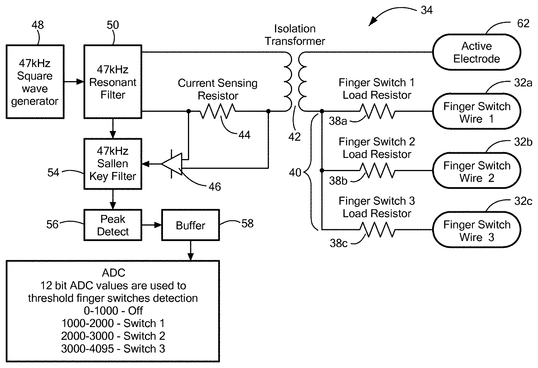
Referring now to FIGS. 2 and 3, the primary winding of the isolation transformer 42 may be electrically coupled to a current sensing resistor 44. The current sensing resistor 44 is a low resistance resistor configured to sense the current flowing through it the form of a voltage drop, which can be detected and amplified. In particular, the current sensing resistor 44 may be coupled to a difference amplifier 46, and other components discussed in more detail below, configured to detect a change in voltage or current across the resistor 44 as a result one of the finger switches 30 being depressed. Upstream of the current sensing resistor 44 is a first radiofrequency oscillator 48 configured to generate a radiofrequency signal and a resonant filter 50 configured to filter the waveform generated by the first radiofrequency oscillator 48 at the same frequency as the waveform. In an exemplary configuration, the first radiofrequency oscillator 48 generates a square waveform at 47 kHz which provides power to the detection circuit 40 after being converted to a sine save by the resonant filter 50. In contrast, the radiofrequency output source 36 includes a second radiofrequency oscillator 52 configured to generator a radiofrequency waveform at approximately in the range of 400 kHz to 500 khz to provide power to at least one of the first and second electrosurgical devices 18 and 22. In an exemplary configuration, the second radiofrequency oscillator 52 generates a waveform at a single frequency of 473 kHz. Thus, the second radiofrequency oscillator 52 generates a radiofrequency waveform approximately 10 times greater than the radiofrequency waveform of the first radiofrequency oscillator 48, which prevents un-differentiable interference between the two oscillators.
Continuing to refer to FIGS. 2 and 3, when the user of, for example, the second electrosurgical hand piece 22 depresses one of the finger switches 30, the circuit between the depressed finger switch and the isolation transformer 42 is shorted and a pathway is created for the flow of current across the isolation transformer 40 as a function of the resistance of its corresponding load resistor. For example, each of the finger switches 30 has an open position in which current does not flow across the isolation transformer 40. When one of the finger switches 30 is depressed into a closed position, the isolation transformer 40 is shorted such that a pathway for current to flow by inductance across the isolation transformer 40 is created from the first radiofrequency oscillator 48, across the isolation transformer 40, through the respective finger switch conductor 32, and through the load resistors 38. The current across the isolation transformer 40 is a function of the respective load resistor 38. Thus, the current sensing resistor 44 can measure this current and calculate a voltage drop across the current sensing resistor 44. In particular, the difference amplifier 46 can amplify the voltage drop across the current sensing resistor 44. The amplified voltage drop can then be filtered by a filter 54. For example, the filter 54 may be a Sallen Key Filter, which is an electronic filter topology configured to implement a second-order active filter. The peak of the filtered voltage drop may then be detected with a peak detector 56 and signal processed by a buffer 58. The buffered voltage drop signal may then be assigned a predetermined energy threshold value, which is then correlated to the particular finger switch 30 that is depressed. For example, four 12 bit ADC predetermined energy threshold values may be assigned to each of the finger switches 30. For example, a value of 0-1000 indicates that no finger switch 30 has been depressed. A value between 1000-2000 indicates finger switch 30a has been depressed, a value between 2000-3000 indicates finger switch 30b has been depressed, and a value between 3000-4095 indicates that finger switch 30 has been depressed. The assigned predetermined threshold values may then be communicated to a one or more processors 60, which in turn communicates with the radiofrequency output source 36 to provide a determined radiofrequency waveform based on which finger switch has been depressed. This waveform may then be transmitted to the active electrode 62 for treatment of tissue.
It will be appreciated by persons skilled in the art that the present invention is not limited to what has been particularly shown and described herein above. In addition, unless mention was made above to the contrary, it should be noted that all of the accompanying drawings are not to scale. A variety of modifications and variations are possible in light of the above teachings without departing from the scope and spirit of the invention, which is limited only by the following claims.
* * * * *
D00000
D00001
D00002
D00003
XML
uspto.report is an independent third-party trademark research tool that is not affiliated, endorsed, or sponsored by the United States Patent and Trademark Office (USPTO) or any other governmental organization. The information provided by uspto.report is based on publicly available data at the time of writing and is intended for informational purposes only.
While we strive to provide accurate and up-to-date information, we do not guarantee the accuracy, completeness, reliability, or suitability of the information displayed on this site. The use of this site is at your own risk. Any reliance you place on such information is therefore strictly at your own risk.
All official trademark data, including owner information, should be verified by visiting the official USPTO website at www.uspto.gov. This site is not intended to replace professional legal advice and should not be used as a substitute for consulting with a legal professional who is knowledgeable about trademark law.