Suture passers adapted for use in constrained regions
Hendricksen , et al. J
U.S. patent number 10,524,778 [Application Number 14/697,494] was granted by the patent office on 2020-01-07 for suture passers adapted for use in constrained regions. This patent grant is currently assigned to Ceterix Orthopaedics. The grantee listed for this patent is Ceterix Orthopaedics, Inc.. Invention is credited to Christopher P. Bender, Michael J. Hendricksen, Mark Y. Hirotsuka, Michael Murillo, Stephen J. Peter.


View All Diagrams
| United States Patent | 10,524,778 |
| Hendricksen , et al. | January 7, 2020 |
Suture passers adapted for use in constrained regions
Abstract
Described herein suture passer apparatus (devices and systems) that may be used to suture tissue within a narrow, confined space. In particular, described herein are suture passers having an elongate body and a bent lower jaw member that houses a tissue penetrator that is adapted to extend laterally through the bend region, and then be laterally deflected from the lower jaw member to a second jaw (e.g. bendable or pivoting) upper member.
| Inventors: | Hendricksen; Michael J. (Redwood City, CA), Murillo; Michael (Menlo Park, CA), Bender; Christopher P. (Oakland, CA), Hirotsuka; Mark Y. (San Jose, CA), Peter; Stephen J. (San Francisco, CA) | ||||||||||
|---|---|---|---|---|---|---|---|---|---|---|---|
| Applicant: |
|
||||||||||
| Assignee: | Ceterix Orthopaedics (Fremont,
CA) |
||||||||||
| Family ID: | 54354318 | ||||||||||
| Appl. No.: | 14/697,494 | ||||||||||
| Filed: | April 27, 2015 |
Prior Publication Data
| Document Identifier | Publication Date | |
|---|---|---|
| US 20150313589 A1 | Nov 5, 2015 | |
Related U.S. Patent Documents
| Application Number | Filing Date | Patent Number | Issue Date | ||
|---|---|---|---|---|---|
| 14681528 | Apr 8, 2015 | ||||
| 61976742 | Apr 8, 2014 | ||||
| Current U.S. Class: | 1/1 |
| Current CPC Class: | A61B 17/0469 (20130101); A61B 17/0485 (20130101); A61B 17/0483 (20130101); A61B 17/0625 (20130101); A61B 17/0482 (20130101); A61B 17/062 (20130101); A61B 2017/06042 (20130101); A61B 2017/00371 (20130101); A61B 2017/0646 (20130101); A61B 2017/0475 (20130101); A61B 2017/06047 (20130101) |
| Current International Class: | A61B 17/04 (20060101); A61B 17/06 (20060101); A61B 17/062 (20060101); A61B 17/064 (20060101); A61B 17/00 (20060101) |
| Field of Search: | ;606/144-148 |
References Cited [Referenced By]
U.S. Patent Documents
| 1037864 | September 1912 | Carlson et al. |
| 2738790 | March 1956 | Todt, Sr. et al. |
| 2748773 | June 1956 | Vacheresse, Jr. |
| 3470875 | October 1969 | Johnson |
| 3580256 | May 1971 | Wilkinson et al. |
| 3807407 | April 1974 | Schweizer |
| 3842840 | October 1974 | Schweizer |
| 3901244 | August 1975 | Schweizer |
| 4021896 | May 1977 | Stierlein |
| 4109658 | August 1978 | Hughes |
| 4164225 | August 1979 | Johnson et al. |
| 4236470 | December 1980 | Stenson |
| 4345601 | August 1982 | Fukuda |
| 4440171 | April 1984 | Nomoto et al. |
| 4553543 | November 1985 | Amarasinghe |
| 4605002 | August 1986 | Rebuffat |
| 4706666 | November 1987 | Sheets |
| 4836205 | June 1989 | Barrett |
| 4957498 | September 1990 | Caspari et al. |
| 4981149 | January 1991 | Yoon et al. |
| 5002561 | March 1991 | Fisher |
| 5011491 | April 1991 | Boenko et al. |
| 5037433 | August 1991 | Wilk et al. |
| 5059201 | October 1991 | Asnis |
| 5059206 | October 1991 | Winters |
| 5112344 | May 1992 | Petros |
| 5129912 | July 1992 | Noda et al. |
| 5139520 | August 1992 | Rosenberg |
| 5156608 | October 1992 | Troidl et al. |
| 5193473 | March 1993 | Asao et al. |
| 5219358 | June 1993 | Bendel et al. |
| 5222962 | June 1993 | Burkhart |
| 5250053 | October 1993 | Snyder |
| 5250055 | October 1993 | Moore et al. |
| 5281237 | January 1994 | Gimpelson |
| 5312422 | May 1994 | Trott |
| 5320633 | June 1994 | Allen et al. |
| 5330488 | July 1994 | Goldrath |
| 5336229 | August 1994 | Noda |
| 5342389 | August 1994 | Haber et al. |
| 5364410 | November 1994 | Failla et al. |
| 5368601 | November 1994 | Sauer et al. |
| 5383877 | January 1995 | Clarke |
| 5389103 | February 1995 | Melzer et al. |
| 5391174 | February 1995 | Weston |
| 5397325 | March 1995 | Della Badia et al. |
| 5403328 | April 1995 | Shallman |
| 5405352 | April 1995 | Weston |
| 5405532 | April 1995 | Loew et al. |
| 5431666 | July 1995 | Sauer et al. |
| 5431669 | July 1995 | Thompson et al. |
| 5437681 | August 1995 | Meade et al. |
| 5454823 | October 1995 | Richardson et al. |
| 5454834 | October 1995 | Boebel et al. |
| 5468251 | November 1995 | Buelna |
| 5474057 | December 1995 | Makower et al. |
| 5478344 | December 1995 | Stone et al. |
| 5478345 | December 1995 | Stone et al. |
| 5480406 | January 1996 | Nolan et al. |
| 5496335 | March 1996 | Thomason et al. |
| 5499991 | March 1996 | Garman et al. |
| 5507756 | April 1996 | Hasson |
| 5507757 | April 1996 | Sauer et al. |
| 5520702 | May 1996 | Sauer et al. |
| 5540704 | July 1996 | Gordon et al. |
| 5540705 | July 1996 | Meade et al. |
| 5562686 | October 1996 | Sauer et al. |
| 5569301 | October 1996 | Granger et al. |
| 5571090 | November 1996 | Sherts |
| 5571119 | November 1996 | Atala |
| 5575800 | November 1996 | Gordon |
| 5578044 | November 1996 | Gordon et al. |
| 5601576 | February 1997 | Garrison |
| 5607435 | March 1997 | Sachdeva et al. |
| 5616131 | April 1997 | Sauer et al. |
| 5618290 | April 1997 | Toy et al. |
| 5626588 | May 1997 | Sauer et al. |
| 5632748 | May 1997 | Beck et al. |
| 5632751 | May 1997 | Piraka |
| 5643289 | July 1997 | Sauer et al. |
| 5645552 | July 1997 | Sherts |
| 5653716 | August 1997 | Malo et al. |
| 5665096 | September 1997 | Yoon |
| 5669917 | September 1997 | Sauer et al. |
| 5674229 | October 1997 | Tovey et al. |
| 5674230 | October 1997 | Tovey et al. |
| 5681331 | October 1997 | de la Torre et al. |
| 5690652 | November 1997 | Wurster et al. |
| 5713910 | February 1998 | Gordon et al. |
| 5728107 | March 1998 | Zlock et al. |
| 5728113 | March 1998 | Sheds |
| 5730747 | March 1998 | Ek et al. |
| 5741278 | April 1998 | Stevens |
| 5749879 | May 1998 | Middleman et al. |
| 5755728 | May 1998 | Maki |
| 5759188 | June 1998 | Yoon |
| 5766183 | June 1998 | Sauer |
| 5792153 | August 1998 | Swain et al. |
| 5797958 | August 1998 | Yoon |
| 5800445 | September 1998 | Ratcliff et al. |
| 5814054 | September 1998 | Kortenbach et al. |
| 5814069 | September 1998 | Schulze et al. |
| 5824009 | October 1998 | Fukuda et al. |
| 5827300 | October 1998 | Fleega |
| 5843126 | December 1998 | Jameel |
| 5865836 | February 1999 | Miller |
| 5871490 | February 1999 | Schulze et al. |
| 5876411 | March 1999 | Kontos |
| 5876412 | March 1999 | Piraka |
| 5895393 | April 1999 | Pagedas |
| 5895395 | April 1999 | Yeung |
| 5897563 | April 1999 | Yoon et al. |
| 5899911 | May 1999 | Carter |
| 5906630 | May 1999 | Anderhub et al. |
| 5908428 | June 1999 | Scirica et al. |
| 5910148 | June 1999 | Reimels |
| 5935138 | August 1999 | McJames, II et al. |
| 5938668 | August 1999 | Scirica et al. |
| 5944739 | August 1999 | Zlock et al. |
| 5947982 | September 1999 | Duran |
| 5980538 | November 1999 | Fuchs et al. |
| 5993466 | November 1999 | Yoon |
| 5997554 | December 1999 | Thompson |
| 6039753 | March 2000 | Meislin |
| 6042601 | March 2000 | Smith |
| 6048351 | April 2000 | Gordon et al. |
| 6051006 | April 2000 | Shluzas et al. |
| 6053933 | April 2000 | Balazs et al. |
| 6056771 | May 2000 | Proto |
| 6071289 | June 2000 | Stefanchik et al. |
| 6077276 | June 2000 | Kontos |
| 6099550 | August 2000 | Yoon |
| 6099568 | August 2000 | Simonian et al. |
| 6113610 | September 2000 | Poncet |
| 6126666 | October 2000 | Trapp et al. |
| 6129741 | October 2000 | Wurster et al. |
| 6139556 | October 2000 | Kontos |
| 6152934 | November 2000 | Harper et al. |
| 6159224 | December 2000 | Yoon |
| 6190396 | February 2001 | Whitin et al. |
| 6221085 | April 2001 | Djurovic |
| 6231606 | May 2001 | Graf et al. |
| 6238414 | May 2001 | Griffiths |
| 6264694 | July 2001 | Weiler |
| 6277132 | August 2001 | Brhel |
| 6322570 | November 2001 | Matsutani et al. |
| 6325808 | December 2001 | Bernard et al. |
| 6355050 | March 2002 | Andreas et al. |
| 6368334 | April 2002 | Sauer |
| 6368343 | April 2002 | Bonutti et al. |
| 6443963 | September 2002 | Baldwin et al. |
| 6511487 | January 2003 | Oren et al. |
| 6533795 | March 2003 | Tran et al. |
| 6533796 | March 2003 | Sauer et al. |
| 6551330 | April 2003 | Bain et al. |
| 6585744 | July 2003 | Griffith |
| 6626917 | September 2003 | Craig |
| 6626929 | September 2003 | Bannerman |
| 6638283 | October 2003 | Thal |
| 6638286 | October 2003 | Burbank et al. |
| 6641592 | November 2003 | Sauer et al. |
| 6719765 | April 2004 | Bonutti |
| 6723107 | April 2004 | Skiba et al. |
| 6770084 | August 2004 | Bain et al. |
| 6833005 | December 2004 | Mantas |
| 6896686 | May 2005 | Weber |
| 6921408 | July 2005 | Sauer |
| 6923806 | August 2005 | Hooven et al. |
| 6923819 | August 2005 | Meade et al. |
| 6936054 | August 2005 | Chu |
| 6972027 | December 2005 | Fallin et al. |
| 6984237 | January 2006 | Hatch et al. |
| 6991635 | January 2006 | Takamoto et al. |
| 6997931 | February 2006 | Sauer et al. |
| 6997932 | February 2006 | Dreyfuss et al. |
| 7004951 | February 2006 | Gibbens, III |
| 7029480 | April 2006 | Klein et al. |
| 7029481 | April 2006 | Burdulis, Jr. et al. |
| 7041111 | May 2006 | Chu |
| 7063710 | June 2006 | Takamoto et al. |
| 7087060 | August 2006 | Clark |
| 7112208 | September 2006 | Morris et al. |
| 7118583 | October 2006 | O'Quinn et al. |
| 7131978 | November 2006 | Sancoff et al. |
| 7153312 | December 2006 | Torrie et al. |
| 7166116 | January 2007 | Lizardi et al. |
| 7175636 | February 2007 | Yamamoto et al. |
| 7211093 | May 2007 | Sauer et al. |
| 7232448 | June 2007 | Battles et al. |
| 7235086 | June 2007 | Sauer et al. |
| 7311715 | December 2007 | Sauer et al. |
| 7344545 | March 2008 | Takemoto et al. |
| 7390328 | June 2008 | Modesitt |
| 7481817 | January 2009 | Sauer |
| 7481826 | January 2009 | Cichocki |
| 7491212 | February 2009 | Sikora et al. |
| 7588583 | September 2009 | Hamilton et al. |
| 7594922 | September 2009 | Goble et al. |
| 7632284 | December 2009 | Martinek et al. |
| 7674276 | March 2010 | Stone et al. |
| 7717927 | May 2010 | Hahn et al. |
| 7722630 | May 2010 | Stone et al. |
| 7731727 | June 2010 | Sauer |
| 7736372 | June 2010 | Reydel et al. |
| 7749236 | July 2010 | Oberlaender et al. |
| 7842050 | November 2010 | Diduch et al. |
| 7879046 | February 2011 | Weinert et al. |
| 7883519 | February 2011 | Oren et al. |
| 7951147 | May 2011 | Privitera et al. |
| 7951159 | May 2011 | Stokes et al. |
| 7972344 | July 2011 | Murray et al. |
| 8298230 | October 2012 | Sutter et al. |
| 8394112 | March 2013 | Nason |
| 8398673 | March 2013 | Hinchliffe et al. |
| 8449533 | May 2013 | Saliman et al. |
| 8465505 | June 2013 | Murillo et al. |
| 8500809 | August 2013 | Saliman |
| 8562631 | October 2013 | Saliman |
| 8632563 | January 2014 | Nagase et al. |
| 8647354 | February 2014 | Domingo |
| 8663253 | March 2014 | Saliman |
| 8702731 | April 2014 | Saliman |
| 8808299 | August 2014 | Saliman et al. |
| 8821518 | September 2014 | Saliman |
| 8888848 | November 2014 | Saliman et al. |
| 8911456 | December 2014 | McCutcheon et al. |
| 8920441 | December 2014 | Saliman et al. |
| 9011454 | April 2015 | Hendrickson et al. |
| 2001/0041938 | November 2001 | Hein |
| 2002/0169477 | November 2002 | Demopulos et al. |
| 2003/0023250 | January 2003 | Watschke et al. |
| 2003/0065336 | April 2003 | Xiao |
| 2003/0065337 | April 2003 | Topper et al. |
| 2003/0078599 | April 2003 | O'Quinn et al. |
| 2003/0078617 | April 2003 | Schwartz et al. |
| 2003/0181926 | September 2003 | Dana et al. |
| 2003/0204194 | October 2003 | Bittar |
| 2003/0216755 | November 2003 | Shikhman et al. |
| 2003/0233106 | December 2003 | Dreyfuss |
| 2004/0117014 | June 2004 | Bryant |
| 2004/0249392 | December 2004 | Mikkaichi et al. |
| 2004/0249394 | December 2004 | Morris et al. |
| 2004/0267304 | December 2004 | Zannis et al. |
| 2005/0033319 | February 2005 | Gambale et al. |
| 2005/0033365 | February 2005 | Courage |
| 2005/0043746 | February 2005 | Pollak et al. |
| 2005/0080434 | April 2005 | Chung et al. |
| 2005/0090837 | April 2005 | Sixto, Jr. et al. |
| 2005/0090840 | April 2005 | Gerbino et al. |
| 2005/0154403 | July 2005 | Sauer et al. |
| 2005/0228406 | October 2005 | Bose |
| 2005/0288690 | December 2005 | Bourque et al. |
| 2006/0020272 | January 2006 | Gildenberg |
| 2006/0047289 | March 2006 | Fogel |
| 2006/0084974 | April 2006 | Privitera et al. |
| 2006/0178680 | August 2006 | Beverly et al. |
| 2006/0282098 | December 2006 | Shelton et al. |
| 2007/0032799 | February 2007 | Pantages et al. |
| 2007/0038230 | February 2007 | Stone et al. |
| 2007/0156174 | July 2007 | Kaiser et al. |
| 2007/0185532 | August 2007 | Stone et al. |
| 2007/0219571 | September 2007 | Balbierz et al. |
| 2007/0250118 | October 2007 | Masini |
| 2007/0260260 | November 2007 | Hahn et al. |
| 2007/0260278 | November 2007 | Wheeler et al. |
| 2008/0086147 | April 2008 | Knapp |
| 2008/0091219 | April 2008 | Marshall et al. |
| 2008/0097482 | April 2008 | Bain |
| 2008/0097489 | April 2008 | Goldfarb et al. |
| 2008/0140091 | June 2008 | DeDeyne et al. |
| 2008/0140094 | June 2008 | Schwartz et al. |
| 2008/0208221 | August 2008 | Murray |
| 2008/0228204 | September 2008 | Hamilton et al. |
| 2008/0234725 | September 2008 | Griffiths et al. |
| 2008/0243147 | October 2008 | Hamilton et al. |
| 2008/0269783 | October 2008 | Griffith |
| 2008/0275553 | November 2008 | Wolf et al. |
| 2008/0294256 | November 2008 | Hagan et al. |
| 2009/0012520 | January 2009 | Hixson et al. |
| 2009/0012538 | January 2009 | Saliman |
| 2009/0018554 | January 2009 | Thorne et al. |
| 2009/0062816 | March 2009 | Weber |
| 2009/0062819 | March 2009 | Burkhart et al. |
| 2009/0105729 | April 2009 | Zentgraf |
| 2009/0105751 | April 2009 | Zentgraf |
| 2009/0112232 | April 2009 | Crainich et al. |
| 2009/0131956 | May 2009 | Dewey et al. |
| 2009/0209998 | August 2009 | Widmann |
| 2009/0216268 | August 2009 | Panter |
| 2009/0228041 | September 2009 | Domingo |
| 2009/0259233 | October 2009 | Bogart et al. |
| 2009/0281619 | November 2009 | Le et al. |
| 2009/0306684 | December 2009 | Stone et al. |
| 2009/0306776 | December 2009 | Murray |
| 2010/0057109 | March 2010 | Clerc et al. |
| 2010/0106169 | April 2010 | Niese et al. |
| 2010/0114137 | May 2010 | Vidal et al. |
| 2010/0121352 | May 2010 | Murray et al. |
| 2010/0130990 | May 2010 | Saliman |
| 2010/0145364 | June 2010 | Keren et al. |
| 2010/0185232 | July 2010 | Hughett et al. |
| 2010/0198235 | August 2010 | Pierce et al. |
| 2010/0217286 | August 2010 | Gerber |
| 2010/0228271 | September 2010 | Marshall et al. |
| 2010/0241142 | September 2010 | Akyuz et al. |
| 2010/0249809 | September 2010 | Singhatat et al. |
| 2010/0280530 | November 2010 | Hashiba |
| 2010/0305581 | December 2010 | Hart |
| 2010/0305583 | December 2010 | Baird et al. |
| 2011/0022061 | January 2011 | Orphanos et al. |
| 2011/0022063 | January 2011 | McClurg et al. |
| 2011/0028998 | February 2011 | Adams et al. |
| 2011/0060350 | March 2011 | Powers et al. |
| 2011/0071563 | March 2011 | Magliani |
| 2011/0087246 | April 2011 | Saliman et al. |
| 2011/0100173 | May 2011 | Stone et al. |
| 2011/0112555 | May 2011 | Overes et al. |
| 2011/0112556 | May 2011 | Saliman |
| 2011/0118760 | May 2011 | Gregoire et al. |
| 2011/0130773 | June 2011 | Saliman et al. |
| 2011/0152892 | June 2011 | Saliman et al. |
| 2011/0190815 | August 2011 | Saliman |
| 2011/0251626 | October 2011 | Wyman et al. |
| 2011/0270306 | November 2011 | Denham et al. |
| 2012/0101524 | April 2012 | Bennett |
| 2012/0283750 | November 2012 | Saliman et al. |
| 2012/0283753 | November 2012 | Saliman et al. |
| 2012/0283754 | November 2012 | Murillo |
| 2012/0303046 | November 2012 | Stone et al. |
| 2013/0072948 | March 2013 | States, III et al. |
| 2013/0085512 | April 2013 | Wyman et al. |
| 2013/0253536 | September 2013 | Harris et al. |
| 2013/0331865 | December 2013 | Murillo et al. |
| 2014/0074157 | March 2014 | Hirotsuka et al. |
| 2014/0188136 | July 2014 | Cournoyer et al. |
| 2014/0222034 | August 2014 | Saliman |
| 2014/0276981 | September 2014 | Hendricksen et al. |
| 2014/0276987 | September 2014 | Saliman |
| 2014/0303625 | October 2014 | Sholev |
| 2015/0034694 | February 2015 | Cappola |
| 2015/0039030 | February 2015 | Saliman et al. |
| 2015/0073442 | March 2015 | Saliman et al. |
| 2015/0088163 | March 2015 | George et al. |
| 2015/0142022 | May 2015 | George et al. |
| 2015/0157317 | June 2015 | Bagaoisan et al. |
| 2015/0173742 | June 2015 | Palese et al. |
| 2015/0173743 | June 2015 | Palese et al. |
| 2015/0257756 | September 2015 | Sauer |
| 2016/0192926 | July 2016 | Hendricksen et al. |
| 2016/0220244 | August 2016 | Murillo et al. |
| 2016/0242765 | August 2016 | George et al. |
| 2017/0027558 | February 2017 | Murillo et al. |
| 2017/0119372 | May 2017 | Peter et al. |
| 2018/0125479 | May 2018 | Saliman et al. |
| 2018/0199931 | July 2018 | Saliman et al. |
| 2018/0303476 | October 2018 | Murillo et al. |
| 201263696 | Jul 2009 | CN | |||
| 101961256 | Feb 2011 | CN | |||
| 103298503 | Sep 2013 | CN | |||
| 103717149 | Apr 2014 | CN | |||
| 0647431 | Apr 1995 | EP | |||
| 2030575 | Mar 2009 | EP | |||
| 2184015 | May 2010 | EP | |||
| 2081481 | Nov 2015 | EP | |||
| 3032847 | Mar 1991 | JP | |||
| 2009138029 | Jun 2009 | JP | |||
| 2009538190 | Nov 2009 | JP | |||
| 376089 | Apr 1973 | SU | |||
| 728848 | Apr 1980 | SU | |||
| 1725847 | Apr 1992 | SU | |||
| WO 92/05828 | Apr 1992 | WO | |||
| WO 95/13021 | May 1995 | WO | |||
| WO98/11825 | Mar 1998 | WO | |||
| WO 98/31288 | Jul 1998 | WO | |||
| WO 99/34744 | Jul 1999 | WO | |||
| WO 99/42036 | Aug 1999 | WO | |||
| WO 99/47050 | Sep 1999 | WO | |||
| WO 01/56478 | Aug 2001 | WO | |||
| WO 02/07607 | Jan 2002 | WO | |||
| WO 02/096296 | Dec 2002 | WO | |||
| WO 03/077771 | Sep 2003 | WO | |||
| WO 2006/001040 | Jan 2006 | WO | |||
| WO 2006/040562 | Apr 2006 | WO | |||
| WO 2010/141695 | Dec 2010 | WO | |||
| WO 2011/057245 | May 2011 | WO | |||
Other References
|
Nord et al.; Posterior lateral meniscal root tears and meniscal repair; Orthopedics Today; 5 pgs; Nov. 2010; retrieved from the internet on Aug. 21, 2014 (http://www.healio.com/orthopedics/arthroscopy/news/print/orthop- edics-today/%7B1b52a700-e986-4524-ac7d-6043c9799e15%7D/posterior-lateral-m- eniscal-root-tears-and-meniscal-repair). cited by applicant . Murillo et al.; U.S. Appl. No. 14/572,485 entitled "Automatically reloading suture passer devices and methods," filed Dec. 16, 2014. cited by applicant . Hendricksen et al.; U.S. Appl. No. 14/659,471 entitled "Suture passer with radiused upper jaw," filed Mar. 16, 2015. cited by applicant . Hendricksen et al.; U.S. Appl. No. 14/681,528 entitled "Suture passers adapted for use in constrained regions," filed Apr. 8, 2015. cited by applicant . Asik et al.; Strength of different meniscus suturing techniques; Knee Sur, Sports Traumotol, Arthroscopy; vol. 5; No. 2; pp. 80-83; (year of publication is sufficiently earlier than the effective U.S. filed and any foreign priority date) 1997. cited by applicant . Asik et al.; Failure strength of repair devices versus meniscus suturing techniques; Knee Surg, Sports Traumatol, Arthrosc; vol. 10; No. 1; pp. 25-29; Jan. 2002. cited by applicant . Arthrex.RTM., Arthrex, Inc., "The Next Generation in Shoulder Repair Technology," Product Brochure from Arthrex, Inc; Naples, Florida, (year of pub. sufficiently earlier than effective US filed and any foreign priority date) 2007, 22 pages. cited by applicant . ArthroCare.RTM. Sportsmedicine, Sunnyvale, CA, SmartStitch.RTM. Suture Passing System with the PerfectPasserTM, Product brochure, (year of pub. sufficiently earlier than effective US filed and any foreign priority date) 2006, 4 pages. cited by applicant . BiPass(TM) Suture Punch, Biomet.RTM. Sports Medicine, Inc., accessed Feb. 29, 2008 at <http://www.arthrotek.com/prodpage.cfm?c=0A05&p=090706> 2 pages. cited by applicant . Boenisch et al.; Pull-out strength and stiffness of meniscal repair using absorbable arrows or Ti-Cron vertical and horizontal loop sutures; Amer. J. of Sports Med.; vol. 27; No. 5 pp. 626-631; Sep.-Oct. 1999. cited by applicant . Cayenne Medical; CrossFix.RTM. II System (product webpage); 4 pgs.; downloaded Nov. 21, 2011 (www.cayennemedical.com/products/crossfix/). cited by applicant . Covidien Surgical; Endo Stitch 10 mm Suturing Device; accessed Dec. 4, 2012 at <http://www.autosuture.com/autosuture/pagebuilder.aspx?topicID- =7407&breadcrumbs=0:63659,30691:0,309:0> 2pages. cited by applicant . Depuy Mitek, Inc; Raynham, MA, "Versalok Surgical Technique for Rotator Cuff Repair: The next generation in rotator cuff repair," Product brochure, (year of pub. sufficiently earlier than effective US filed and any foreign priority date) 2007, 18 pages. cited by applicant . Duerig, T. et al., "An overview of nitinol medical applications" Materials Science and Engineering A273-275, pp. 149-160; May 1999. cited by applicant . Linvatec Conmed Company, Largo, Florida, Product descriptions B17-19, B21; Tissue Repair Systems, Tissue Repair Accessories, and Master Arthroscopy Shoulder Instrument Set, (printed on or before Aug. 2007), 4 pages. cited by applicant . Ma et al; "Biomechanical Evaluation of Arthroscopic Rotator Cuff Stitches," J Bone Joint Surg Am, Jun. 2004; vol. 86(6):1211-1216. cited by applicant . Medsfera; Suturing devices; accessed Dec. 4, 2012 at <http://www.medsfera.ru/shiv.html> 13 pages. cited by applicant . Nho et al; "Biomechanical fixation in Arthroscopic Rotator Cuff Repair," Arthroscopy: J of Arthroscop and Related Surg; vol. 23. No. 1, Jan. 2007: pp. 94-102. cited by applicant . Rimmer et al.; Failure Strength of Different Meniscal Suturing Techniques; Arthroscopy: The Journal of Arthroscopic and Related Surgery; vol. 11; No. 2; pp. 146-150; Apr. 1995. cited by applicant . Schneeberger, et al; "Mechanical Strength of Arthroscopic Rotator Cuff Repair Techniques: An in Vitro Study," J Bone Joint Surg Am., Dec. 2002; 84:2152-2160. cited by applicant . Smith Fast-Fix Meniscal Repair System (product webpage); 4 pgs.; downloaded Nov. 21, 2011 (http://endo.smith-nephew.com/fr/node.asp?NodeId=3562). cited by applicant . Strobel; Manual of Arthroscopic Surgery (1st Edition); Springer Verlag, Hiedelberg .COPYRGT. 2002; pp. 127-129; Dec. 15, 2001. cited by applicant . USS SportsMedicine ArthoSewTM Single Use Automated Suturing Device with 8.6 mm ArthroPort Cannula Set, Instructions for Use, <http:www.uss-sportsmed.com/imageServer.aspx?contentID=5020&contenttyp- e=application/pdf> accessed Apr. 25, 2007, 2 pages. cited by applicant . USS SportsMedicine ArthroSewTM Suturing Device, <http://www.uss-sportsmed.com/SportsMedicine/pageBuilder.aspx?webPageI- D=0&topicID=7141&xs1=xsl/productPagePrint.xsl>, product description, accessed Apr. 25, 2007, 3 pages. cited by applicant . Hirotsuka et al.; U.S. Appl. No. 15/132,211 entitled "Pre-tied surgical knots for use with suture passers," filed Apr. 18, 2016. cited by applicant . Murillo et al.; U.S. Appl. No. 15/216,482 entitled "Automatically reloading suture passer devices that prevent entanglement," filed Jul. 21, 2016. cited by applicant . Dictionary.com; Adjacent (definition); 5 pgs.; retrieved from the internet (http://www.dictionary.com/browse/adjacent) on Apr. 5, 2016. cited by applicant . Ceterix; Novocut suture manager; retrieved from the internet (https://web.archive.org/web/20150314071511/http://www.ceterix.com:80/im-- a-physician/products/) on Oct. 11, 2017; 1 page; Mar. 12, 2015. cited by applicant . Ceterix; Novocut suture manager; retrieved from the internet (https://www.youtube.com/watch?v=6txgBJxvnuA) on Oct. 11, 2017; 1 page; Mar. 5, 2015. cited by applicant . Saliman; U.S. Appl. No. 15/853,531 entitled "Suture methods for forming locking loops stitches," filed Dec. 22, 2017. cited by applicant . Chinese Notification to Grant Patent Right for Invention Application No. 201510163638.1 dated May 28, 2019. cited by applicant . Chinese Notification of Correction of Notice of Grant of Patent Right for Invention Application No. 201510163638.1 dated Jun. 5, 2019. cited by applicant. |
Primary Examiner: Schwiker; Katherine H
Attorney, Agent or Firm: Hainer, Jr.; Norman F.
Parent Case Text
CROSS REFERENCE TO RELATED APPLICATION
This application is a continuation-in-part of U.S. patent application Ser. No. 14/681,528, filed Apr. 8, 2015, titled "SUTURE PASSERS ADAPTED FOR USE IN CONSTRAINED REGIONS," which claims the benefit of U.S. Provisional Patent Application No. 61/976,742, filed Apr. 8, 2014, titled "SUTURE PASSERS ADAPTED FOR USE IN CONSTRAINED REGIONS". This application is herein incorporated by reference in its entirety.
This patent application may be related to one or more of U.S. patent application Ser. No. 14/265,848, filed on Apr. 30, 2014, titled "SUTURE PASSER WITH RADIUSED UPPER JAW," now U.S. Pat. No. 9,011,454; U.S. patent application Ser. No. 14/292,695, filed on May 30, 2014, titled "SUTURE METHODS FOR FORMING LOCKING LOOPS STITCHES," Publication No. US-2014-0276987-A1; U.S. patent application Ser. No. 13/247,892, filed on Sep. 28, 2011, titled "MENISCUS REPAIR," Publication No. US-2012-0283750-A1; U.S. patent application Ser. No. 13/323,391, filed on Dec. 12, 2011, titled "SUTURE PASSER DEVICES AND METHODS," Publication No. US-2012-0283753-A1; U.S. patent application Ser. No. 13/893,154, filed on May 13, 2013, titled "SUTURE PASSER DEVICES AND METHODS," Publication No. US-2013-0331865-A1; U.S. patent application Ser. No. 13/759,006, filed on Feb. 4, 2013, titled "SUTURE PASSERS," Publication No. US-2014-0222034-A1; U.S. patent application Ser. No. 14/546,942, filed on Nov. 18, 2014, titled "SUTURE PASSER AND METHOD FOR HIP LABRUM REPAIR," Publication No. US-2015-0073442-A1; U.S. patent application Ser. No. 13/844,252, filed on Mar. 15, 2013, titled "SUTURE PASSERS AND METHODS OF PASSING SUTURE," Publication No. Publication No. US-2014-0276981-A1; and U.S. patent application Ser. No. 14/572,485, filed on Dec. 16, 2014, titled "AUTOMATICALLY RELOADING SUTURE PASSER DEVICES AND METHODS".
Claims
What is claimed is:
1. A suture passer apparatus adapted for insertion into a knee joint, the apparatus comprising: an elongate body having a proximal end connected to a proximal handle and a distal end region, wherein the elongate body extends in a long axis; a lower jaw member extending from the distal end region of the elongate body wherein the lower jaw member is axially fixed relative to the elongate body, the lower jaw member including a bend relative to the long axis of the elongate body at a proximal end of the lower jaw member, wherein a bottom surface of the lower jaw member from the bend to a rounded distal end region of the lower jaw member is flat and extends in a straight line to the rounded distal end region; an upper jaw member extending from the distal end region of the elongate body, the upper jaw member having an arc-shaped profile that is biased to curve away from the long axis of the elongate body in a same direction as the bend, and wherein the upper jaw member has a retracted configuration in which the upper jaw member is entirely within the elongate body; and a tissue penetrator housed within the lower jaw member configured to slide distally in the lower jaw member beyond the bend and extend laterally out of the lower jaw member to transfer a loop of suture from the lower jaw member through the upper jaw member.
2. The apparatus of claim 1, wherein the bend is at an angle that is between 5 degrees and 40 degrees relative to the long axis of the elongate body for inserting the lower jaw member into the knee joint.
3. The apparatus of claim 1, wherein the tissue penetrator is a thin, flat and elongate Nitinol member.
4. The apparatus of claim 1, wherein the upper jaw member is configured to move from the retracted configuration to an extended configuration to axially align with the lower jaw member with respect to the long axis, engage tissue and receive the loop of suture and the tissue penetrator.
5. The apparatus of claim 1, wherein the upper jaw member comprises a suture capture region adapted to receive the loop of suture on the upper jaw member when the tissue penetrator is retracted proximally after contacting the upper jaw member.
6. The apparatus of claim 1, wherein the upper jaw member comprises a suture capture comprising a clamping member.
7. The apparatus of claim 1, wherein the lower jaw member comprises a deflection surface within the lower jaw member to deflect the tissue penetrator laterally out of the lower jaw member when the tissue penetrator is slid distally.
8. The apparatus of claim 1, wherein a thickness of the lower jaw member is less than a width of the lower jaw member over a majority of the lower jaw member.
9. A suture passer apparatus adapted for insertion into a knee joint, the apparatus comprising: an elongate body having a proximal end connected to a proximal handle and a distal end region, wherein the elongate body extends in a long axis; a lower jaw member axially fixed to the distal end region of the elongate body, the lower jaw member including a bend of between 5 degrees and 40 degrees relative to the long axis of the elongate body at a proximal end of the lower jaw member, wherein a bottom surface of the lower jaw member from the bend to a rounded distal end region of the lower jaw is flat and extends in a straight line to the rounded distal end region; an upper jaw member configured to move axially from a retracted position in which the upper jaw member is entirely within the elongate body to an extended position in which the upper jaw member is extended from the elongate body, wherein the upper jaw member is biased to curve away from the long axis of the elongate body in a same direction as the bend as it is moved to the extended position; and an elongate, thin and flat tissue penetrator housed within the lower jaw member configured to slide distally in the lower jaw member beyond the bend and extend a distal tip region laterally out of the lower jaw member to transfer a loop of suture from the lower jaw member, through a tissue and through the upper jaw member.
10. A method of suturing tissue, the method comprising: inserting a suture passer into a body region, wherein the suture passer is loaded with a loop of suture in a lower jaw of the suture passer, wherein the suture passer comprises an elongate body extending in a long axis, an upper jaw coupled to the elongate body, the upper jaw comprising an arc-shaped profile and a retracted position in which the upper jaw is completely retracted within the elongate body; and wherein the lower jaw is coupled to a distal end region of the elongate body, the lower jaw including a bend relative to the long axis of the elongate body at a proximal end of the lower jaw, wherein a bottom surface of the lower jaw from the bend to a rounded distal end region of the lower jaw is flat and extends in a straight line to the rounded distal end region; positioning a target tissue adjacent to the lower jaw while the upper jaw is in the retracted position; extending the upper jaw from the elongate body so that the target tissue is straddled and captured between the lower jaw and the upper jaw, wherein the arc-shaped profile is biased to curve away from the long axis of the elongate body in a same direction as the bend in the lower jaw as the upper jaw is extended; closing the lower jaw and the upper jaw to at least partially clamp the target tissue between the lower jaw and the upper jaw; and pushing a distal end region of a tissue penetrator from within the lower jaw to deflect laterally out of the lower jaw through the target tissue and through the upper jaw, wherein the distal end region of the tissue penetrator is carrying the loop of suture.
11. The method of claim 10, wherein positioning the target tissue adjacent to the lower jaw comprises positioning a torn knee meniscus adjacent to the lower jaw.
12. The method of claim 10, wherein positioning the target tissue adjacent to the lower jaw comprises sliding the lower jaw under an inferior surface of a knee meniscus, the method further comprising extending the upper jaw from the retracted position until the upper jaw is adjacent the superior surface of the knee meniscus.
13. The method of claim 10, further comprising loading the loop of suture into the lower jaw by loading the loop of suture into the distal end region of the tissue penetrator.
14. The method of claim 10, wherein closing the lower jaw and the upper jaw comprises squeezing a first control on a proximal handle of the suture passer.
15. The method of claim 14, wherein pushing the distal end region of the tissue penetrator from within the lower jaw to deflect laterally out of the lower jaw through the target tissue and through the upper jaw comprises squeezing a second control on the proximal handle of the suture passer.
16. The method of claim 10, wherein pushing the distal end region of the tissue penetrator from within the lower jaw to deflect laterally out of the lower jaw through the target tissue and through the upper jaw comprises retaining a proximal portion of the tissue penetrator within the lower jaw as the distal end region of the tissue penetrator is extended through the upper jaw.
17. The method of claim 10, further comprising stripping the loop of suture from the tissue penetrator and retracting the tissue penetrator back into the lower jaw, wherein the loop of suture is retained on the upper jaw after retracing the tissue penetrator back into the lower jaw.
18. The method of claim 10, wherein pushing the distal end region of the tissue penetrator from within the lower jaw to deflect laterally out of the lower jaw through the target tissue and through the upper jaw comprises pushing the distal end region of the tissue penetrator against a clamping mechanism in the upper jaw as the distal end region of the tissue penetrator is extended through the upper jaw.
19. The method of claim 10, further comprising removing the suture passer from the target tissue and releasing the loop of suture from the suture passer as the suture passer is removed from the target tissue.
Description
INCORPORATION BY REFERENCE
All publications and patent applications mentioned in this specification are herein incorporated by reference in their entirety to the same extent as if each individual publication or patent application was specifically and individually indicated to be incorporated by reference.
FIELD
Suture passer apparatus, including devices and systems, as well as methods of making and using such apparatus are described herein. In particular, suture passer apparatus adapted for use in narrow, confined, and/or difficult to access regions of a body, such as a knee joint.
BACKGROUND
Suturing of tissue during surgical procedures is time consuming and can be particularly challenging in difficult to access body regions and regions that have limited clearance, such as regions partially surrounded or covered by bone. For many surgical procedures, it is necessary to make a large opening in the human body to expose the area requiring surgical repair. However, in many cases, accessing the tissue in this manner is undesirable, increasing recovery time, and exposing the patient to greater risk of infection.
Suturing instruments ("suture passers" or "suturing devices") have been developed to assist in accessing and treating internal body regions, and to generally assist a physician in repairing tissue. Although many such devices are available for endoscopic and/or percutaneous use, these devices suffer from a variety of problems, including limited ability to navigate and be operated within the tight confines of the body, risk of injury to adjacent structures, problems controlling the position and/or condition of the tissue before, during, and after passing the suture, and difficulties loading the suture into the device, particularly for threading multiple suture loops.
For example, some surgical instruments used in endoscopic procedures are limited by the manner in which they access the areas of the human body in need of repair. In particular, the instruments may not be able to access tissue or organs located deep within the body or that are in some way obstructed. In addition, many of the instruments are limited by the way they grasp tissue, apply a suture, or recapture the needle and suture. Furthermore, many of the instruments are complicated and expensive to use due to the numerous parts and/or subassemblies required to make them function properly. Suturing remains a delicate and time-consuming aspect of most surgeries, including those performed endoscopically.
Some variations of suture passers, such as those described in U.S. Pat. No. 7,377,926 to Taylor, have opposing jaws that open and close over tissue. One, or in some variations, both, jaws open, scissor-like, so that tissue may be inserted between the open jaws. Unfortunately, such devices cannot be adequately positioned for use in hard to navigate body regions such as the joints of the body, including the knee (e.g., meniscus) and the shoulder because there is not room within the confines of the body (e.g., joint region) to open the scissoring jaws.
The knee joint is one example of a tissue region that is notoriously difficult to access. For example, the meniscus is a C-shaped piece of fibrocartilage which is located at the peripheral aspect of the joint (e.g., the knee) between the condyles of the femur and the tibia on the lateral and medial sides of the knee. The central two-thirds of the meniscus has a limited blood supply while the peripheral one third typically has an excellent blood supply. Acute traumatic events commonly cause meniscus tears in younger patients while degenerative tears are more common in older patients as the menisci become increasingly brittle with age. Typically, when the meniscus is damaged, a torn piece of meniscus may move in an abnormal fashion inside the joint, which may lead to pain and loss of function of the joint. Early arthritis can also occur due to these tears as abnormal mechanical movement of torn meniscal tissue and the loss of the shock absorbing properties of the meniscus lead to destruction of the surrounding articular cartilage. Occasionally, it is possible to repair a torn meniscus. While this may be done arthroscopically, surgical repair using a suture has proven difficult to perform because of the hard-to-reach nature of the region and the difficulty in placing sutures in a way that compresses and secures the torn surfaces.
Arthroscopy typically involves inserting a fiberoptic telescope that is about the size of a pencil into the joint through an incision that is approximately 1/8 inch long. Fluid may then be inserted into the joint to distend the joint and to allow for visualization of the structures within that joint. Then, using miniature instruments which may be as small as 1/10 of an inch, the structures are examined and the surgery is performed.
The meniscus of the knee is just one example of a tissue that is difficult to access so that appropriate suturing may be performed.
Thus, there is a need for methods and apparatuses (e.g., devices and systems) for suturing tissue, particularly tissue in difficult to access regions of the body including the joints (shoulder, knee, etc.). In particularly, it has proven useful to provide a device that may simply and reliably reach and pass sutures within otherwise inaccessible tissue regions. Such devices should be extremely low profile, and may be adapted or otherwise configured to fit in the tight spaces of the joints. Finally, would be useful to provide suturing apparatuses that allow selective and specific penetration of the tissue by both the tissue penetrator (needle element) and a jaw so that complex (including right-angled) suturing patterns may be achieved.
There is also a need for methods and apparatuses for suturing tissue. In particular, it has proven useful to provide a device that may simply and reliably reach and pass sutures within otherwise inaccessible tissue regions. Further, there is a need for suture passers that can be automatically loaded (or preloaded) pass multiple lengths (e.g., bights) of suture though the tissue without requiring that they be manually reloaded, either within the tissue or by withdrawing them from the tissue.
Although limited space in tight joints is frequently a limiting factor in soft tissue repair within joints, described herein are apparatus configured to facilitate suture passing in such tight joints. The apparatus (e.g., devices and systems) described herein may pass sutures vertically through soft tissue, with a tissue penetrator (e.g., needle) that extends out of a lower jaw at or near a 90.degree. angle. After passing through the tissue, the tissue penetrator contacts an upper jaw (or in come variations, a condyle protective element), which deflects the needle again, so that the needle extends in a serpentine path, either deflected distally or deflected proximally.
SUMMARY OF THE DISCLOSURE
In general, described herein suture passer apparatus (devices and systems) that may be used to suture tissue within a narrow, confined space.
For example, a suture passer may include an elongate body and a fixed or laterally movable (e.g., extendable and retractable) lower jaw member from which a tissue penetrator (needle) may extend. The tissue penetrator may be held within the lower jaw member and may be extended distally from a side region of the lower jaw member and deflected from the side of the lower jaw through the tissue, particularly when the tissue is held between the lower jaw and an upper jaw. The lower jaw may be bent or straight. In some variations the lower jaw may be hinged or bendable. The suture passer may also include an upper jaw that acts as a shield or deflector to deflect the needle (tissue penetrator) after it extends through the tissue from the lower jaw. The upper jaw may be adapted to extend from within the elongate body, rotate/pivot relative to the elongate body, and/or may be fixed relative to the elongate body. The upper jaw may be extremely thin and sufficiently strong to deflect the tissue penetrator. In some variations the upper jaw is pre-biased to curve away from the elongate axis of the elongate body, e.g., to form a v-shaped opening when extended.
The upper jaw may include a suture securing region near its distal end so that a suture passed by a tissue penetrator is held by the upper jaw until the device is retracted from the tissue.
Some variations of suture passers and methods described herein include only a lower jaw that is fixed or bendable and/or slideable. The lower jaw houses a tissue penetrator that may be extended laterally from a side-opening in the lower jaw. Although an upper jaw is not included, a separate shield member may be positioned laterally from the target tissue to be sutures, and used to deflect the tissue penetrator from non-target tissue.
In variations including an upper arm (opposite from the arm housing the tissue penetrator) may also include a suture retainer on upper arm. For example, the upper arm may include a passage, opening, or loop through which the tissue penetrator passes after being deflected against a tissue deflection surface. When the tissue penetrator is retracted back through the tissue, the suture (which may be loaded into the tissue penetrator and pushed through the tissue from the lower jaw with the tissue penetrator) may be retained. A loop or bight of tissue may be passed and retained on the opposite side of the target tissue, e.g., in the upper arm. In some variations the second (upper) jaw may include a suture retainer that includes a leaf spring or other clamping mechanism that clamps the suture between two or more surfaces to hold it. In some variations the upper jaw includes a region that is adapted to be penetrated by the tissue penetrator (e.g., a mesh region, a region that is made of a "soft" material such as silicone, etc.); when retracting the needle back to the lower jaw, the suture will be retained by the upper jaw.
Also described herein are suture passer apparatus having lower jaws (housing the tissue penetrator) that have very narrow (e.g., less than 20 mm, less than 10 mm, less than 5 mm) widths. When operating these devices, they may be turned sideways to position within a confined space, and rotated over to operate. The distal end of the suture passer, and in particular a suture passer having a very narrow lower jaw, may be bent or curved to one side, enhancing positioning within the narrow confines of the tissue.
For example, a suture passer apparatus adapted for insertion into a knee joint as described herein may include: an elongate body having a proximal end connected to a proximal handle and a distal end region, wherein the elongate body extends in a long axis; a lower jaw member extending from the distal end region of the elongate body, the lower jaw including a bend relative to the long axis of the elongate body at a proximal end of the lower jaw, wherein a bottom surface of the lower jaw from the bend to the distal end of the lower jaw is flat and extends in a straight line to a rounded distal end region; an upper jaw member extending from a distal end region of the elongate body and bendable relative to the elongate body, wherein the upper jaw member bends away from the long axis of the elongate body in a same direction as the bend in the lower jaw member; and a tissue penetrator housed within the lower jaw member configured to slide distally in the lower jaw member beyond the bend and extend laterally out of the lower jaw member to transfer a loop of suture from the lower jaw member through the upper jaw member.
In general, the bend in the lower jaw member may be engineered specifically to facilitate the insertion into the knee joint. For example, the bend may be any angle is between about 5 degrees and about 40 degrees, relative to the long axis of the elongate body. The bend may be located at any position along the lower jaw; e.g., it may be located at the proximal end of the lower jaw, or more distally from the proximal jaw. In some variations, the bend may be located opposite from the hinge point of the upper jaw, or distal (e.g., slightly distal) to the hinge location of the upper jaw, in variations in which the upper jaw is pivoting.
The tissue penetrator (which may be referred to as a needle herein) may be generally thin, flat and elongate, and may be made of any appropriate material (e.g., Nitinol). In general, the tissue penetrator must be configured so that it can be bent multiple times during operation of the device. For example, the distal end region (e.g., 1 mm to 50 mm) of the tissue penetrator may be bent within the lower jaw member to navigate the bend (e.g., the 5 degrees to 40 degree bend), and then deflected out of the lower jaw member to pass the suture from the lower jaw member to the upper jaw member. Once the suture is passed through and engaged by the upper jaw member, the tissue penetrator is retracted, pulling back within the lower jaw member.
For example, in some variations the lower jaw member comprises a deflection surface at or within the lower jaw member to deflect the tissue penetrator laterally out of the lower jaw member when the tissue penetrator is slid distally.
As mentioned, in some variations, the lower jaw member is fixed relative to the elongate body. In some variations, the bent lower jaw member is configured to pivot relative to the elongate body.
The upper jaw member may comprise a suture capture region adapted to receive the loop of suture on the upper jaw when the tissue penetrator is retracted proximally after contacting the upper jaw member. For example, the upper jaw may include a suture capture comprising a clamping member. The lower jaw member may be thinner than a width of the lower jaw member over most of the proximal to distal length of the lower jaw member.
For example, a suture passer apparatus adapted for insertion into a knee joint may include: an elongate body having a proximal end connected to a proximal handle and a distal end region, wherein the elongate body extends in a long axis; a lower jaw member extending from the distal end region of the elongate body, the lower jaw including a bend of between 5 degrees and 40 degrees relative to the long axis of the elongate body at a proximal end of the lower jaw, wherein a bottom surface of the lower jaw from the bend to the distal end of the lower jaw is flat and extends in a straight line to a rounded distal end region; an upper jaw member extending from a distal end region of the elongate body and pivotable relative to the elongate body, wherein the upper jaw member pivots away from the long axis of the elongate body in a same direction as the bend in the lower jaw member; and an elongate, thin and flat tissue penetrator housed within the lower jaw member configured to slide distally in the lower jaw member beyond the bend and extend a distal tip region laterally out of the lower jaw member to transfer a loop of suture from the lower jaw member and through the upper jaw member.
Also described herein are methods of suturing tissue (e.g., using any of the devices described above). For example a method may include: loading a loop of suture into a lower jaw member of a suture passer, wherein the suture passer comprises an elongate body extending in a long axis, an upper jaw pivotally connected relative to the lower jaw, wherein the lower jaw member extends from a distal end region of the elongate body, the lower jaw including a bend relative to the long axis of the elongate body at a proximal end of the lower jaw, wherein a bottom surface of the lower jaw from the bend to the distal end of the lower jaw is flat and extends in a straight line to a rounded distal end region; positioning a target tissue in between the lower jaw and the upper jaw; closing the first jaw towards the second jaw to at least partially clamp the target tissue between the first jaw and the second jaw; and pushing a distal end region of a tissue penetrator from within the lower jaw to deflect laterally out of the lower jaw through the target tissue and through the upper jaw, wherein the distal end region of the tissue penetrator is carrying the loop of suture.
Positioning the target tissue in between the lower jaw and the upper jaw may include positioning a torn knee meniscus between the lower jaw and the upper jaw. Positioning the target tissue in between the lower jaw and the upper jaw may comprise sliding the lower jaw under an inferior surface of a knee meniscus and placing the upper jaw against the superior surface of the knee meniscus.
Loading the loop of suture into the lower jaw member of the suture passer may include loading the loop of suture into the distal end of the tissue penetrator.
In any of the variations described herein, the proximal handle may include a pair of controls, including a first control (e.g., lever, grip, handle, etc.) that actuates pivoting/bending of the upper jaw and a second control (e.g., lever, grip, handle, etc.) that actuates extension/retraction of the tissue penetrator from the lower jaw to the upper jaw. Either or both controls may be spring operated, or otherwise biased in one position (e.g., so that the upper jaw is biased in a pivoted open position and/or the tissue penetrator is biased in a retracted, e.g., within the lower jaw, position). Closing the first jaw towards the second jaw may comprise squeezing a first control on a proximal handle of the suture passer. In addition or alternatively, pushing the distal end region of the tissue penetrator from within the lower jaw to deflect laterally out of the lower jaw through the target tissue and through the upper jaw may include squeezing a second control on the proximal handle of the suture passer.
Pushing the distal end region of the tissue penetrator from within the lower jaw to deflect laterally out of the lower jaw through the target tissue and through the upper jaw may include retaining a proximal portion of the tissue penetrator within the lower jaw as the distal end region is extended through the upper jaw.
Any of the methods described herein may also include stripping the loop of suture from the tissue penetrator and retaining the loop of suture on the upper jaw after retracing the tissue penetrator back into the lower jaw. For example, pushing the distal end region of the tissue penetrator from within the lower jaw to deflect laterally out of the lower jaw through the target tissue and through the upper jaw may include pushing the distal end region of the tissue penetrator against a clamping mechanism in the upper jaw as the distal end region is extended through and out of the upper jaw.
Any of the methods described herein may also include releasing the loop of suture from the suture passer as the suture passer is removed from the tissue. For example, the loop may be released from the upper jaw by holding and/or pulling on the limbs of the suture loop while retracting the suture passer out of the apparatus.
BRIEF DESCRIPTION OF THE DRAWINGS
FIG. 1A shows an example of a suture passer device having an elongate body with a proximal handle region and a distal lower jaw housing a tissue penetrator that can exit from a lateral opening to extend perpendicularly (or nearly perpendicularly) from the lower jaw. FIGS. 1B-1E show variations of different distal jaw regions that may be used with the elongate body and handle regions shown in FIG. 1A.
In FIG. 1B, a side view of the distal end region of the suture passer includes a lower jaw that houses a tissue penetrator and is configured to slide distally to proximally relative to (e.g., from) the distal end of the elongate body. An upper jaw comprising a pre-bent or curved strip of metal is adapted to deflect the tissue penetrator distally (though it may be adapted to deflect it proximally).
FIG. 1C is similar to FIG. 1B, except the lower jaw member is fixed relative to the elongate body and does not slide distally to proximally. As in FIG. 1B, the upper jaw may slide/extend distally and retract proximally from the elongate body and deflect the tissue penetrator.
FIG. 1D is similar to FIG. 1B, however the upper jaw is adapted to include a passage or deflector and/or tissue retainer at the distal end that retains the bight of suture after is passed from the lower jaw to the upper jaw.
FIG. 1E is similar to FIG. 1D except the lower jaw (as in FIG. 1C) is fixed relative to the elongate body.
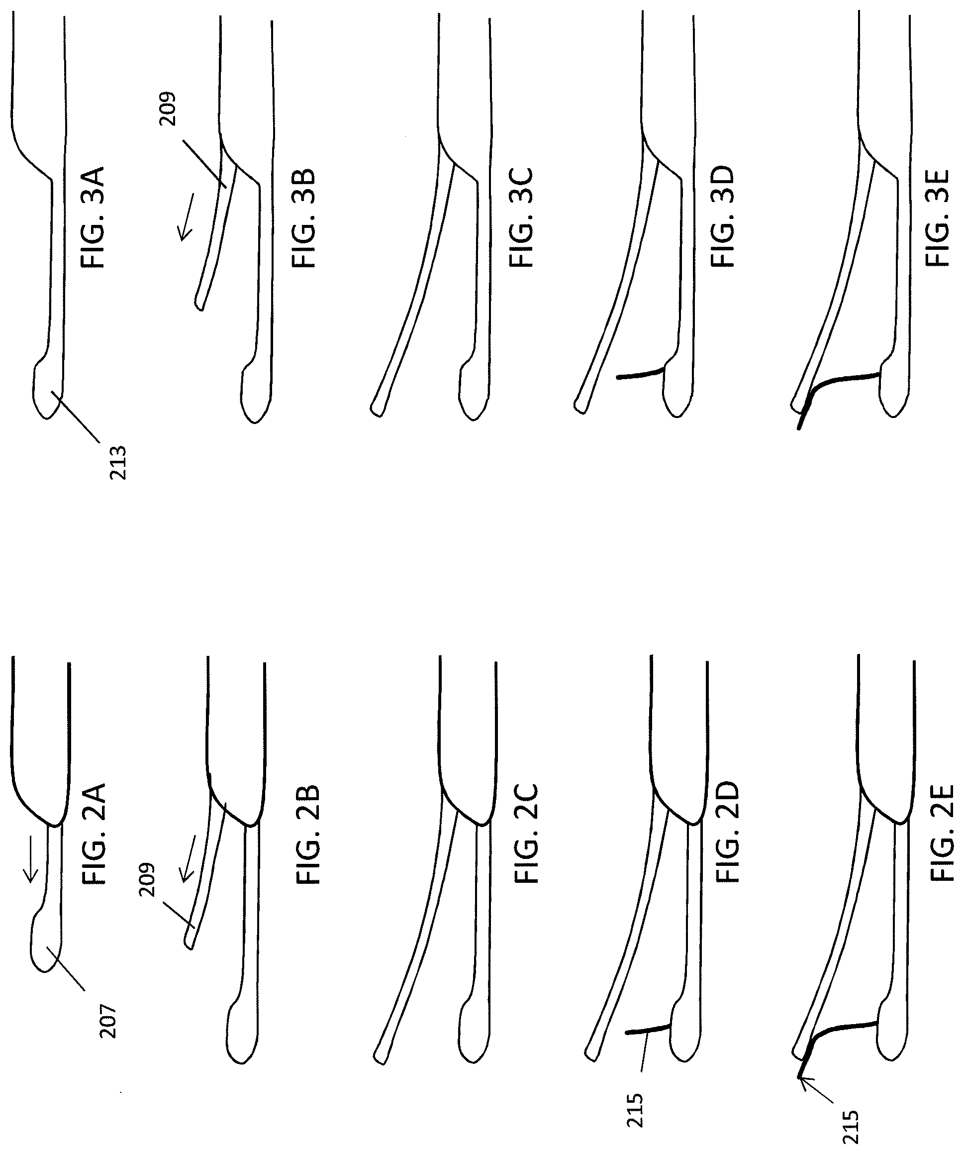
FIGS. 2A-2E illustrates operation of a suture passer having a distal end with a sliding lower jaw housing a tissue penetrator and an upper jaw adapted as a thin deflector that extends and retracts into the elongate body (including, in some variations, completely retracting into the elongate body). In FIG. 2A, the lower jaw with the tissue penetrator (which may be pre-loaded with suture) is extended and may be positioned against a target tissue. In FIG. 2B the upper jaw extends from the elongate body so that a target tissue (such as a meniscus of the knee) is positioned between the upper and lower jaws. In FIG. 2C the upper and lower jaws are completely extended. In FIG. 2D the tissue penetrator (needle) is extended laterally from within the lower jaw and extended across the tissue between the jaws. In FIG. 2E the tissue penetrator is deflected a second time so that it is directed distally by the upper jaw. The tissue penetrator may carry a suture bight through the tissue and it may be retained on the opposite side of the tissue, either by a suture retainer region or by friction between the tissue and suture, or both.
FIGS. 3A-3E illustrates a similar method of operating a suture passer having a fixed lower jaw (e.g., fixed and non-slideable relative to the elongate body).
FIGS. 4A-4F illustrate operation of a suture passer passing a pair of suture bights using a suture passer having a distal end similar to the one shown in FIGS. 1C and 3A-3E. The distal end of the suture passer is shown in profile, while the tissue is shown transparent (e.g., in partial section) to illustrate the passage of the needle and suture therethrough.
FIG. 5 illustrates one variation of an upper jaw having a hook at the distal end. The hook may be used to capture and pull a bight of suture that has been passed through the tissue.
FIGS. 6A-6C illustrate the operation of a suture passer having a clamping collar, configured as an outer collar or tube that can be used to close the `jaws` formed by an upper and lower jaw member of any of the distal end variations described, including those shown in FIGS. 1B-1E. This may allow the device to clamp on the target tissue held between the jaws, as illustrated.
FIGS. 7A-7E illustrate operation of a variation of the distal end of a suture passer device such as the one shown in FIG. 1D, in which the lower jaw is axially slideable distally to proximally, as is the upper jaw, and the upper jaw include a suture retainer region at the distal end. In general, the upper and lower jaws are independently movable (and slideable) as is the tissue penetrator.
FIGS. 8A-8E illustrates a side view of the operation of a variation of the distal end of a suture passer device such as the one shown in FIG. 1E, in which the lower jaw is fixed relative to the elongate body and the upper jaw is axially slideable distally to proximally, and the upper jaw include a suture retainer region at the distal end.
FIGS. 9A and 9B show a variation of a suture passer having a bent or curved lower jaw (in this example the lower jaw is fixed relative to the elongate body), and an axially sliding upper jaw that is adapted to deflect the tissue penetrator from the lower jaw).
FIGS. 10A and 10B illustrate the use of a suture passer having just a lower jaw with a lateral opening from which a tissue penetrator may extend. Instead of an upper jaw that deflects and/or guides the tissue penetrator, a separate shield or deflector may be used over the tissue.
FIG. 11 illustrates one variation of a suture that may be used, in which a shape memory material (e.g., metal, plastic, etc.) or a material having a relative stiffness may be used to help form and/or hold open the loop of suture that is passed by the apparatus. In FIG. 11 the suture material is a woven material that includes a shape set material that helps hold the bight of suture open.
FIG. 12A shows flipping of a bight of suture that has been passed through a target tissue (shown as a meniscus) so that the suture bights are changed from a proximal orientation (as pushed by a suture passer that extends distally) to be oriented distally, which may allow them to be more easily grasped and manipulated.
FIGS. 12B and 12C illustrate upper jaw members that are adapted at their distal ends to pull or change the direction of the bight after it has been pulled through the tissue.
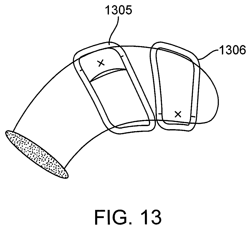
FIG. 13 illustrates the use of anchors or clamps to secure the tissue to be sutured (e.g., meniscus) so that the needle or suture passer does not shift or move the tissue undesirably during operation of the device.
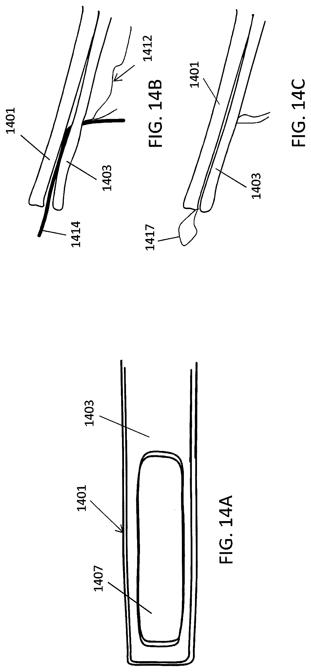
FIG. 14A shows a bottom view of one variation of an upper jaw (second jaw) having an opening into which the tissue penetrator may extend; the upper jaw is formed of a pair of leaflets with one leaflet being deflectable from the other so that the tissue penetrator can extend through the hole/opening and between the leaflets and distally out of the upper jaw, as illustrated in the side views of FIGS. 14B and 14C. Retracting the tissue penetrator leaves a loop or bight of suture behind, as shown in FIG. 14C.
FIG. 15 shows a variation of the upper jaw of FIG. 14A-14C in which the leaflets forming the upper jaw may be moved laterally relative to each other to capture and/or release a loop of suture.
FIG. 16A shows another variation of an upper jaw including a loop or opening at the distal end that may capture or retain a bight of suture passed from the lower jaw. FIGS. 16B and 16C show bottom and side views, respectively.
FIG. 17 illustrates another variation of the distal end of a suture passer apparatus having a suture retainer region at the upper jaw.
FIG. 18 illustrates another distal end of a suture passer apparatus having a suture retainer region at the upper jaw as well as a deflection region that may be displaced relative to the rest of the upper jaw when the tissue penetrator extend from the lower jaw.
FIGS. 19A and 19B illustrate another variation of an upper jaw including a suture retainer region.
FIGS. 20A and 20B show another variation of an upper jaw including a suture retainer region.
FIG. 21 shows another variation of an upper jaw including a suture retainer region.
FIG. 22A shows another variation of an upper jaw including a suture retainer region configured as a soft material attached to a more rigid or hard material at the distal end of the upper jaw. FIGS. 22B and 22C illustrate similar variations.
FIG. 23 shows another variation of an upper jaw including a suture retainer region configured as a soft material attached to a more rigid or hard material that is adapted to retain a bight of suture passed from the opposite jaw by the tissue penetrator.
FIGS. 24A and 24B illustrate another variation of a tissue penetrator having an upper jaw that is adapted to deflect a tissue penetrator and retain a bight of suture passed by the tissue penetrator to the upper jaw.
FIG. 25 shows one variation of a needle and pusher that may be used.
FIGS. 26A and 26B illustrate variation of suture passers having a distal end region that includes a bendable upper and bendable lower jaw.
FIG. 27 illustrates the operation of a suture passer apparatus having a bendable lower jaw.
FIG. 28 illustrates the articulating attachment of a jaw member for use with a bending lower and/or upper jaw member.
FIG. 29 show a hinged lower jaw and an upper jaw that may be axially slid (extended and/or retracted); the lower jaw may be clamped to secure the tissue between the upper and lower jaws, preventing sliding or misfiring of the tissue penetrator.
FIG. 30 is a side view that illustrates another variation of an upper jaw having a rigid or semi-rigid region more proximal to a flexible (and narrower) distal region. The distal region is also curved relative to the straighter, flatter more proximal region.
FIG. 31 shows a top view of another variation of an upper jaw having a pair of tensioning region that may be used to curve the upper jaw, e.g., by pulling or pushing on the tensioning members.
FIGS. 32A and 32B show a side view and top view, respectively, of a distal end of a lower jaw member that is particularly thin (width, x), particularly as compared to the height (y), e.g., heath is more than 1.5x width, more than 2x width, more than 2.5x width, etc.). FIG. 32C illustrates a curved variation, in which the tip is curved or bent to the left or right.
FIG. 33 illustrates another variation of a suture passer in which the lower jaw include a tissue penetrator that is not deflected out of the lower jaw by extending axially (e.g., sliding) or not exclusively extended by sliding, but is (at least in part) extended by pushing the distal region of the tissue penetrator without sliding (e.g., by pulling a deflector proximally).
FIG. 34 shows one variation of a section through a distal end of a suture passer having an upper and a lower jaw in which the lower and upper jaws nest together to allow a relatively narrow profile.
FIG. 35 shows another variation of a section through a distal end of a suture passer having a distal including an upper jaw nested with a lower jaw.
FIG. 36A shows a side perspective view of a suture passer device having a distal end with a sliding lower jaw and a bendable (pivot able) upper jaw; a tissue penetrator may be housed within the lower jaw (which in this variation is adapted as a pre-loaded suture containing cartridge) and may be extended from the lower jaw to the upper jaw, where it is again deflected distally to pass a bight of suture to the upper jaw. FIG. 36B is an enlarged view of the distal end of the device with the upper jaw bent away from the long distal-to-proximal axis of the device and the lower jaw extended distally.
FIGS. 37A-37D illustrate another variation of a suture passer having a fixed, bent lower jaw and a bendable/pivotable upper jaw, as described above in FIG. 9B. FIGS. 37E and 37F illustrate the operation of the apparatus in FIGS. 37A-37D. The distal end of the suture passer is shown in profile, while the tissue is shown transparent (e.g., in partial section) to illustrate the passage of the needle and suture therethrough.
DETAILED DESCRIPTION
In general, described herein are suture passer apparatus and methods of making and using them. Any of the suture passer apparatuses described herein may include features or elements that may be adapted for use with any of the other features or elements of the suture passers, except where specifically noted.
For example, described herein are suture passers that are particularly well adapted for insertion and manipulation in tight, narrow and difficult to access regions. Suture passers previously described, and illustrated in FIGS. 36A-36B, included an elongate body 3601 with a proximal handle region having controls for operating the apparatus. The distal end included a lower jaw member 3605 that is axially (distally-to-proximally) slideable relative to the elongate body, and an upper jaw member 3603 that is bent or bendable relative to the elongate body and/or the lower jaw. For example, the upper jaw may be pivotably attached 3613 to the end region of the elongate body 3601 so that it could be bent and clamp onto tissue held between the upper and lower jaws when the lower jaw was axially (distally) extended. A needle (also referred to generically as a tissue penetrator) which can carry a suture or loop (bight) of suture housed with the lower jaw may be extended laterally from a side of the lower jaw so that the tip of the tissue penetrator extends across the jaw formed by the upper and lower jaws and contacts the upper jaw where it is deflected distally or proximally. The suture may be retained by the upper jaw (or in the tissue near the upper jaw) when the tissue penetrator is retracted.
Thus, described herein are variations of suture passers that can include a laterally (axially) retractable upper jaw that may be extremely thin (e.g., less than 10 mm, less than 5 mm, less than 4 mm, less than 3 mm, less than 2 mm).
FIG. 1A shows a body of an elongate suture passer including an elongate body extending distally from a proximal handle 105. The elongate body 101 has a distal end 103 to which a first (and in some variations a second) jaw may extend and/or be attached. The proximal handle 105 may include controls for controlling the movements of the jaw(s), and tissue penetrator. FIGS. 1B-1E illustrate various distal end configurations. For example, in FIG. 1B, the distal end includes a lower jaw member 107 that is configured to slide axially distally and proximally relative to the elongate body (e.g., in line with the elongate body). The upper jaw 109 is also configured to slide distally and proximally from within the elongate body to form a distal-facing (v-shaped) opening surrounding the tissue to be sutured. In FIG. 1B, the upper jaw is thin and acts as a protective member that prevents the tissue penetrator 115 (shown extended in FIG. 1B) from extending across the jaws and into the opposite side; instead, the tissue penetrator 115 is deflected distally along the bottom of the upper jaw member 109.
The upper jaw in the variation shown in FIG. 1B is similar to that shown in FIG. 1B, however the lower jaw member 113 does not move axially, but is instead fixed, and may be integral with, the elongate body. The lower jaw 107 in FIG. 1D is similar to the lower jaw of FIG. 1B, however, the upper jaw 111 includes a suture capture region 119 (which may also be referred to as a suture retainer, trap, suture capture, or suture snare) at or near the distal end region. The tissue penetrator 115 extending from the lower jaw member passes through the upper jaw 111 so that it extends out of the distal end of the upper jaw; when the tissue penetrator is retracted back into the lower jaw 107, a suture being pushed through the tissue by the tissue penetrator from the lower jaw member will remain held by the suture retainer 119 in the upper jaw 111. Any appropriate suture retainer may be used. Examples of suture retainer regions are described below, and may include a leaf-spring region that is displaced by the tissue penetrator as well as edge (e.g., jagged) regions that may trap and/or hold the suture.
FIG. 1E also shows a side perspective view of a distal end of a suture passer as described above, having a lower jaw member that is fixed and extends from the distal end of the elongate body, and an upper jaw member that is axially slideable and include a suture retainer region 119.
The variations shown in FIGS. 1B-1E are suture passers with very thin upper jaws (e.g., the upper jaw may be less than 2 mm thick, less than 1 mm thick, less than 0.5 mm thick, etc.). When used in knee meniscus repair, the primary purpose of this upper jaw is to protect condyle surfaces from the needle that comes out of the lower jaw. Protection of the condyle is achieved by having the thin upper jaw be hard enough to deflect the needle. The upper jaw may be sufficiently bendable to curve and bend away from the lower jaw as it is extended out of the elongate body, as illustrated. For example, the upper jaw may be formed of a shape memory material such as Nitinol.
FIGS. 2A-2E illustrate the distal end variation shown in FIG. 1B in operation. To position the tissue penetrator around a target tissue, the lower jaw member 207 may be first extended distally from the distal end of the elongate body, as shown in FIG. 2A. Thereafter, or before the lower jaw has been completely extended, the upper jaw 209 may be extended from the distal end of the elongate body, as shown in FIG. 2B. In FIG. 2C, both the upper and lower jaws have been fully extended around a target tissue (e.g., the meniscus in a knee). Thereafter, as shown in FIG. 2D, the tip of the tissue penetrator 215 housed completely within the lower jaw may be extended from the lower jaw, though the tissue and against the upper jaw, where the tip is deflected distally. A suture, e.g., a loop or bight of suture, may be include and may be passed with the tissue penetrator from the lower to the upper jaw.
FIGS. 3A-3E illustrate the operation of a distal end of suture passer similar to the variation shown in FIG. 1C, having a rigidly fixed lower jaw 213. The extended lower jaw 213 may be positioned within the tissue, e.g., on one side of the target tissue, and typically has a narrow and thin profile, allowing it to be positioned within the tissue and into even difficult to access regions. As described below in reference to FIGS. 9A and 9B, the lower jaw may be bent (or in other variations, bendable). In FIGS. 3A-3E the lower jaw does not slide distally or proximally relative to the elongate body; instead, only the upper jaw 209 slides distally and proximally. In FIG. 3B, the upper jaw 209 is shown extended distally. FIG. 3C shows the upper jaw fully extended and the tissue penetrator is then extended across the tissue as shown in FIGS. 3D-3E.
FIGS. 4A-4F illustrate the operation of one variation of a tissue penetrator as described above. The distal end of the tissue penetrator illustrated in FIGS. 4A-4F has a fixed lower jaw 407 that is rigidly connected to the distal end region of the elongate body, and a thin, strong, upper jaw deflector 409 can be extended distally by sliding out of the elongate body and curving up slightly as it extends outward. In FIG. 4A, the lower jaw member may be positioned on one side of the meniscus, and the upper jaw member may be extended from the distal end of the elongate body (the proximal end of the lower jaw member), as shown in FIG. 4B. In FIG. 4C, the tissue penetrator 415 is extended across and though the meniscus 414 between the upper and lower jaws, passing a loop (bight) of suture though the meniscus along with the tissue penetrator. The tissue penetrator (needle) and suture are passed through the meniscus. The tissue penetrator deflects off the upper jaw away from the femoral condyle and carries a bight of suture beyond the superior surface of the meniscus. In FIG. 4D the tissue penetrator has been retracted, leaving the first bight of suture through the meniscus and between the superior surface of the meniscus 417 and the femoral condyle 419. The tissue penetrator is retracted, leaving behind the suture bight (the friction between the needle hole through the meniscus and the suture retains the suture as the needle is retracted). The suture passer may then be repositioned around the tissue, loaded with the second bight of suture (which may be, for example, the opposite end of the suture forming the first loop) and against passed through the tissue, as shown in FIG. 4E. The suture passer has been moved to a new location, and another bight of suture is passed through the meniscus in the same manner as shown in FIGS. 4C and 4D. Once the suture passer is removed, the two bight regions extending through the meniscus may be grasped and pulled and/or knotted (e.g., to each other) to secure the tissue, as shown in FIG. 4F. For example, the suture passer may be pulled away from the suture bights, leaving the suture bights in location through the meniscus. A second tool is then used to retrieve the suture bights. Such a tool could be a hook, a crab claw, etc. In some variations a hook or grasper may be used, including an upper jaw having a hook region allowing it to grip and manipulate the suture loops, as illustrated in FIG. 5. In FIG. 5, a hook feature exists at the end of the upper jaw, allowing the suture passer upper jaw to be the tool used to retrieve the suture bights.
The method shown in FIGS. 4A-4F illustrates operation of a device having an upper jaw without a suture trap (suture capture region). In some variations, the lower jaw may also be fixed (e.g., does not slide axially relative to the elongate shaft/body) to facilitate a device shaft that is as thin as possible by eliminating internal features that allow for a sliding lower jaw.
In any of the variations described herein, the upper and lower jaws of the suture passer may be adapted to clamp, gab, grasp or otherwise hold secure the tissue between the upper and lower jaw to prevent it from tearing during the procedure, and from moving when the tissue penetrator is applied against the tissue. This may reduce misalignment of needle as it is passed through the tissue.
Thus, any of the devices described herein may be adapted to include a clamping element, such as a sleeve, tube, etc., that drives or allows the distance (e.g., angle) between the upper and lower jaws to be reduced. For example, in FIGS. 6A-6C, an outer cannula 603 (e.g., sleeve) may be driven distally to push against the outer sleeve, causing the thin, and somewhat flexible upper jaw member 601 to close towards the lower jaw 611, as shown in the progression from FIGS. 6A-6C. Similarly, moving the sleeve/cannula proximally allows the upper jaw to expand up and away from the lower jaw, further opening the distal-facing opening.
In FIGS. 6A-6C, the thin upper jaw is shown as an upper jaw that can be advanced and retracted from the device shaft, perhaps telescopically, while the lower jaw is fixed relative to the distal end of the elongate body. Having the upper jaw retracted allows the device to be easily inserted into the joint, and in the case of the knee, may allow the lower jaw to be easily inserted underneath the meniscus. Then, due to its thinness, the upper jaw can readily be advanced above the meniscus. The clamping mechanism (cannula or sleeve) that is shown in FIGS. 6A-6C as a tube. As mentioned, by advancing the clamping mechanism, the upper jaw clamps down on the lower jaw, compressing any tissue between the upper and lower jaws. Retracting the tube allows the clamp to be released.
FIGS. 7A-7E illustrate the operation of the suture passer device having a sliding upper and sliding lower jaw that may both be independently slide (axially) into and out of the distal end region of the elongate body to form a v-shaped distal opening, as described above for FIG. 1D. In this example, the upper jaw 701 is thin, but includes a suture retainer region 703 at the distal end portion of the upper jaw. To position the device, the lower jaw 705 may be extended from the distal end of the elongate body and slide under or adjacent to a target tissue. The upper jaw may then be extended out of the distal end of the elongate body and extend across the target tissue from another side. Once the tissue is held between the jaws, as shown in FIG. 7C, a needle (tissue penetrator) may be extended from the lower jaw toward the upper jaw, as shown in FIG. 7D. The needle may be a bendable, yet sharp, member having a sufficient column strength to be pushed through tissue while carrying a suture (e.g., in a hook, eye, or other portion at or near the distal end of the tissue penetrator). For example, a tissue penetrator may be a stainless steel or Nitinol material that is extended distally in the lower jaw until it is deflected at the lateral opening in the lower jaw to direct the tip of the tissue penetrator out of the lower jaw laterally at nearly 90.degree. relative to the long axis of the lower jaw. In the example shown in FIG. 7E, the tip of the tissue penetrator eventually contacts the upper jaw 701, where it is deflected by the upper jaw and directed distally (although as mentioned, it could be directed proximally). The tissue penetrator in FIG. 7E passes through a channel, or opening that is configured as a suture retainer/trap 703. The suture retainer catches and holds the suture (e.g., suture loop/bight) when the tip of the tissue penetrator is retracted back to the lower jaw (not shown).
FIGS. 8A-8E illustrate a similar mechanism of operation for a suture passer such as the suture passer distal end region shown in FIG. 1E. In FIGS. 8A-8E, as in FIGS. 7A-7E, the upper jaw 801 includes a suture retainer/trap 803, however in FIGS. 8A-8E the lower jaw 805 is fixed (e.g., does not slide) relative to the upper jaw.
Any of the suture passers described herein may include a bend or bendable region in an upper or lower jaw to help position the distal end of the device in even narrow and constrained regions of a tissue such as a knee or shoulder joint. For example, FIGS. 9A and 9B illustrate an apparatus having a lower jaw that is fixed relative to the more proximal elongate body from which the lower jaw 901 extends. As shown in the profile view of FIGS. 9A and 9B, the fixed lower jaw 901 is angled or curved relative to the elongate body region 905 of the apparatus. The very thin upper jaw 903 is configured as a deflector for a tissue penetrator, as mentioned above, and, in some embodiments, can be advanced and retracted into the elongate body 905. In other embodiments, the very thin upper jaw 903 is fixed (e.g., does not slide) and/or pivoting relative to the lower jaw and the elongate body. The angled or curved lower jaw is intended to provide a shape that provides easier access in tight joints. As explicitly mentioned above, any of the suture passer apparatuses described herein may include features or elements that may be adapted for use with any of the other features or elements of the suture passers, except where specifically noted. For example, the bent lower jaw of FIG. 9B may be used with a pivoting upper jaw as illustrated in FIGS. 36A-36B. FIG. 37 provides another example of a device having a pivoting upper jaw and a bent lower jaw.
In general, the upper (or second) jaw is configured to deflect the tissue penetrator that laterally exits from the distal end region of the lower jaw at an angle (e.g., an angel between 60-125 degrees, relative to the long axis of the lower jaw and/or the long axis of the elongate body). However, in some variations an integrated upper jaw/deflector is not included, but instead a separate shield/deflector member may be used. FIGS. 10A and 10B illustrate the use of a separate shield 1001 with a "one armed" suture passer 1005. In FIGS. 10A and 10B, a knee joint including a femoral condyle 1007 is shown. The shield may be inserted before the procedure is performed, and is a protective shield 1001 that is placed between the femoral condyle 1007 and the meniscus 1009 prior to suture passing. After placing the shield, the suture passer 1005, the distal end of which consists of only a shaft and fixed lower jaw, is slid underneath the meniscus 1009. The tissue penetrator and suture are then passed from the lower jaw, through the meniscus, and then the tip of the tissue penetrator deflects off of the shield away from the femoral condyle. The simplicity of the suture passer apparatus in his example (without a second jaw member) may allow the size of the device to be minimized.
All of the methods and apparatuses described herein typically include the use of a suture. An appropriate suture may be used. For example, braided or monofilament suture, and/or sutures of any appropriate material, including bioabsorbable materials (e.g., polymeric materials). It may be of benefit to make the suture bight self-expanding or opening, to allow the suture bight to be more easily captured by a tool, or in some variations by the second/upper jaw. For example, if the apparatus does not include a suture capture region (e.g., on the second or upper jaw member), a self-expanding suture may be more easily captured if the bight is opened on the superior surface of the meniscus after suture passing; this may make it easier to retrieve with a tool. As shown in FIG. 11, the suture forming the suture bight may include a shape set material (e.g., Nitinol wire) within or on the suture. For example, the suture may include an over-braid having a shape-set wire within the braid. When the bight exits the meniscus after suture passing, the wire expands to create a large open loop that provides an easy target for a retrieval tool.
The orientation of the loop within the tissue may also be adjusted by the apparatus to make it easier to retrieve. For example, FIG. 12A illustrate a method of orienting the loop of a bight so that the loop is more easily accessible by a tool accessing the tissue from the same direction as the suture passer. In FIG. 12A, the suture is flipped from a distal (e.g., away from the entry point of the apparatus in the tissue) to a proximal (towards the entry point of the apparatus into the tissue) orientation. FIGS. 12B and 12C illustrate variations of apparatuses that are adapted to flip the suture bight proximally to make the bight easier to retrieve. When the upper jaw is retracted (after the needle has been retracted), the distal end of the upper jaw may pull on the suture bight and flip it proximally. For example, in FIG. 12B the upper jaw includes a large opening though which the tissue penetrator, and therefore the suture bight left behind upon removal of the tissue penetrator, passes. The loop (shown as a hook in FIG. 12C) pulls the bight distally before passing over the bight as the upper jaw is retracted proximally, similar to what is shown in FIG. 12A.
Any of the variations described herein may be used with one or more anchors to hold or secure the target tissue relative to the apparatus when suturing. For example, in particular, when the suture passing apparatus is not adapted to clamp or hold of secure the portion of the tissue around the suture, the tissue (e.g., meniscus) may move when the needle begins to penetrate. This unintended movement may cause the needle to deflect/buckle, resulting in a misfire of the suture passer. In FIG. 13, temporary clamps 1305, 1306 are placed on the meniscus to fix the meniscus and prevent any motion of the meniscus. After placing the clamps the suture passing system can be introduced to pass suture. Another potential benefit of the clamp could be alignment markers, which are used to align the device to the clamp to facilitate precise targeting of the needle and suture passing. The clamps are then removed after the suture is placed. The clamps can also have mating features that facilitate docking of the suture passer to the clamp. This configuration of suture passer and temporary clamp could allow for suture positioning to be less sensitive to device or tissue movement during suture placement.
As mentioned above, any of the thin, sliding upper jaws may include a suture capture (e.g., "trap") that holds the suture in the upper jaw as the tissue penetrator is retracted proximally back into the lower jaw. FIGS. 14A-14C show one variation of an upper jaw having a suture capture formed by two layers of material. In FIG. 14A, a bottom view of the upper jaw shows the thin upper jaw having two layers. The top layer 1401 is solid and hard enough to deflect the needle away from condyle surfaces. The bottom layer 1403 is flexible and provides a spring force up against the top layer. In the bottom view of FIG. 14A, the bottom layer 1403 includes a window region 1407 for the tissue penetrator to pass through and then deflect off of the top layer 1401. The tissue penetrator and suture then penetrate between the distal tips of the two layers and travel beyond the distal tips. This is illustrated in FIG. 14B (showing the tissue penetrator 1414 between the two layers carrying a suture 1417). In FIG. 14C, when tissue penetrator is retracted, the spring force between the two layers grips and retains the suture 1417 bight beyond the tip of the upper jaw. Therefore, when the device is removed from the joint the suture bight is trapped by the upper jaw and is pulled from the tissue. To enhance the suture retainer, either of the layers could have teeth on them.
In another embodiment of FIGS. 14A-14C, the upper jaw is retractable and as it is retracted, the lower layer of the upper jaw may retract farther than the top layer; as a consequence, the suture bight may be cinched between the two layers, trapping the suture and allowing the suture bight to be removed from the joint with the device. This is illustrated in FIG. 15.
FIGS. 16A-16C illustrate another variation of an upper jaw having a suture retainer. In FIGS. 16A-16C, the upper jaw includes two pieces that are in the same plane, to minimize thickness and the relative motion between the pieces. The outer piece 1601 cinches to the inner piece 1603 to cinch down on the suture. Alternatively, a one piece upper jaw with a window could be retracted into the shaft to "snare" the suture. A window in a one piece thin upper jaw may include snaring features that could assist in catching and holding onto the suture as the upper jaw is retracted into the shaft. In FIG. 17, the snare feature and window are slightly lower than the deflective surface of the upper jaw for the purpose of ensuring that the needle passes through the window.
FIG. 18 illustrates another variation of a suture retainer on the upper jaw. In FIG. 18, an upper jaw with a snaring feature 1803 also has a leaf spring region 1805 that deflects slightly when the needle hits it. This deflection helps to ensure that the needle and suture travel through the window and above the snaring feature.
Alternatively, in some variations the distal end of the upper jaw member may be adapted (e.g., by doubling back over itself) to form a compression region that may be displaced by the tissue penetrator, rather than requiring a separate layer. The very distal end region may include an opening or passage for the tissue penetrator to continue to extend distally past the distal end of the upper jaw, or distal movement of the tissue penetrator may be prevented by the bend formed in the upper jaw. FIGS. 19A-19B and 20A-10B illustrate variations of upper jaws that include a suture retainer formed by doubling the material forming the upper jaw back onto itself.
In FIG. 19A, the distal end region forms a suture capture or "trap" in the thin upper jaw. The suture traps 1903, 2003 on the distal end provides a spring force to retain the suture from the tissue penetrator 1905, 2005. FIGS. 19A and 20A show alternate embodiments of spring mechanisms that could trap the suture onto the upper jaw when retracting the tissue penetrator. In FIGS. 19A-20B, these suture traps in the upper jaws have windows at the distal end to allow the needle to pass through the trap and leave a suture bight distal of the trap. FIG. 21 illustrates another variation of a suture capture (suture trap) that also clamps (or springs) down to nest over the lower jaw and create a smooth profile for inserting the device into the tissue.
In some variations, the upper jaw includes a suture capture region that is formed of a material that can be penetrated by the tissue penetrator but that provides sufficient friction to retain the suture when the tissue penetrator is withdrawn from the upper jaw member. For example, FIGS. 22A-22C illustrates a thin upper jaw with two layers, a hard upper layer 2201 that deflects the needle and a soft lower layer 2203 (for example, silicone) that the tissue penetrator (e.g., needle) can penetrate and travel through. When the needle is retracted, the soft lower layer would apply friction to the suture to retain the suture bight in the upper jaw. FIG. 22B shows a variation including the soft material 2203 just at or near the distal end of the device; the material may provide a soft and/or slippery surface to prevent damage to the tissue into which the upper jaw is inserted. In FIG. 23C, the soft material 2203' (for example, silicone) forming part of the suture trap at the end of the upper jaw is intended to be penetrated by the tissue penetrator that can pass through the soft material forming the suture trap, and when the needle retracts, the suture bight is retained in the suture trap. The cross section of the upper jaw (shown in the inset of FIG. 22C) could have rails 2209 on the side to guide the tissue penetrator into the suture capture trap.
FIG. 23 illustrates another variation of a suture capture that is formed by a soft material. In the upper jaw of FIG. 23, there are two layers, a hard upper layer 2301 and soft lower layer 2305. However, in this embodiment the hard upper layer 2301 deflects slightly when the tissue penetrator 2307 hits it, encouraging the tissue penetrator to pass between the two layers. When the needle retracts, the pinch force between the hard and soft layer retains the suture in the upper jaw.
FIG. 24A illustrates two concepts for upper jaws including suture capture. In both concepts, the upper jaw/needle combination deflects the needle proximally. In the first concept, a second deflecting feature is intended to deflect the needle back down to the lower jaw where a suture tray may exist. In the second concept, the needle continues to travel proximally toward the upper jaw hinge region where a suture trap exists.
In FIG. 24B, similar to that shown in FIG. 24A, a tissue penetrator that is deflected proximally and back down to the lower jaw picks up suture in the lower jaw. This concept could result in a continuous suture passer. With one pass, the tissue penetrator drops off the suture in the lower jaw, and a second tissue penetrator pass can then pick up the suture, etc.
As mentioned above, any of the apparatuses described herein may be used with any appropriate tissue penetrator (e.g., needle). In general, the tissue penetrator may be an elongate, thin and sharp (at the distal end) apparatus that is adapted to pass a suture, and may include a suture retainer region, such as an eyelet, hook, clamp, etc. In general, a tissue penetrator is coupled at the proximal end within the lower jaw so that it can be extended and retracted, e.g., by pushing/pulling on the proximal end. FIG. 25 illustrates one variation of a tissue penetrator that is shuttled between the lower and upper jaw. The tissue penetrator has features on the proximal end that allow the lower jaw to release the tissue penetrator so that the tissue penetrator and suture can dock in the upper jaw.
FIGS. 26A and 26B illustrate examples of upper and lower jaws that articulate to allow the suture passer to conform to the anatomy that suture passer is operating in. Thus, in these examples, both the upper and lower jaws may pivot relative to the elongate body to change the angle.
In FIG. 27, the lower jaw is adapted to pivot (e.g., upwards). This may be advantageous in the confines of the knee when accessing a meniscus, since the shaft is often entering the joint at an angle to get above the anterior portion of the meniscus. Thus, a pivoting lower jaw may provide easier access in tight joints. The lower jaw 2701 in FIG. 27 may be adapted for use in a suture passer such as the variation shown in FIGS. 36A-36B, having a sliding lower jaw member housing a tissue penetrator and a pivoting upper jaw. The tapered lower jaw may be adapted to slide within a keyway in the shaft to allow the lower jaw to advance/retract in addition to pivoting upwards. FIG. 27 demonstrates how having a lower jaw with an upwardly bent angle or hinge may be beneficial in placing the distal end of the suture passer when the access portal into the joint must be placed above the anterior horn of the same meniscus to be repaired. The portal above the meniscus may force an approach vector that is pointing downward at the tibial plateau. However, when the lower jaw is placed inferior to the meniscus, it may be easier to get it in place if the lower jaw traverses parallel with the tibial plateau. In FIG. 28, a lower jaw could advance/retract and pivot in an upwardly (or downwardly) curved shaft where the keyway is also curved.
FIG. 29 illustrates a side view of a device with a very thin, extendable/retractable upper jaw with a lower jaw that clamps. Thus, the lower jaw may house the sliding tissue penetrator but may also be adapted to pivot and therefore clamp tissue between the upper 2903 and lower jaws 2901. The upper jaw may be similar to the upper jaws shown in FIGS. 1B-1E (e.g., may be thin and configured to deflect the tissue penetrator). In addition to improved access, the clamping lower jaw 2901 feature may mitigate the challenge of the movement of meniscus as the tissue penetrator begins to penetrate the meniscus. The clamping mechanism could be facilitated by tensioning a cable or a linkage.
Another variation of the configuration for the upper jaw is shown in FIG. 30. In this example, the upper jaw may be configured as a clamping upper jaw (e.g., see the variation shown in FIGS. 36A-36B) with a rigid section and a flexible section. Both sections may have hard elements on the inferior surface that could deflect the needle away from non-target (e.g., condyle surfaces). The rigid section may provide a clamping region of the upper jaw. The end of the rigid section may correspond with the end of the tooth on the lower jaw to maximize the effectiveness of the clamp. The inferior surface of the clamping region may be straight to maximize clamp effectiveness and the s
References
-
healio.com/orthopedics/arthroscopy/news/print/orthopedics-today/%7B1b52a700-e986-4524-ac7d-6043c9799e15%7D/posterior-lateral-meniscal-root-tears-and-meniscal-repair
-
arthrotek.com/prodpage.cfm?c=0A05&p=090706
-
autosuture.com/autosuture/pagebuilder.aspx?topicID=7407&breadcrumbs=0:63659
-
medsfera.ru/shiv.html
-
endo.smith-nephew.com/fr/node.asp?NodeId=3562
-
uss-sportsmed.com/SportsMedicine/pageBuilder.aspx?webPageID=0&topicID=7141&xs1=xsl/productPagePrint.xsl
-
dictionary.com/browse/adjacent
-
ceterix.com:80/im-a-physician/products
-
youtube.com/watch?v=6txgBJxvnuA
D00000
D00001
D00002
D00003
D00004
D00005
D00006
D00007
D00008
D00009
D00010
D00011
D00012

D00013
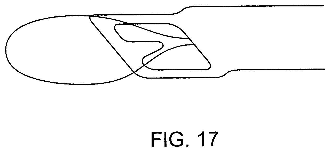
D00014

D00015

D00016

D00017

D00018
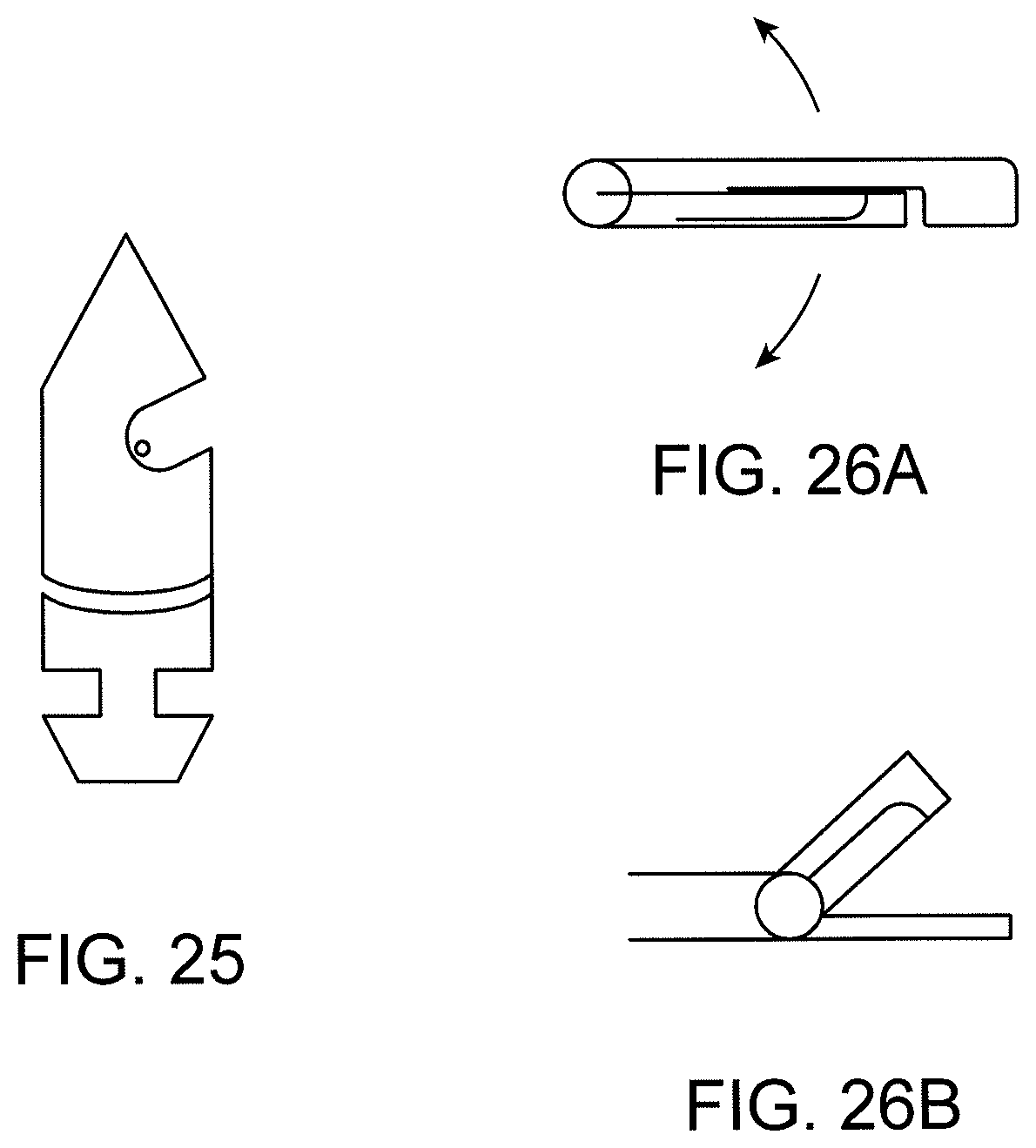
D00019

D00020

D00021
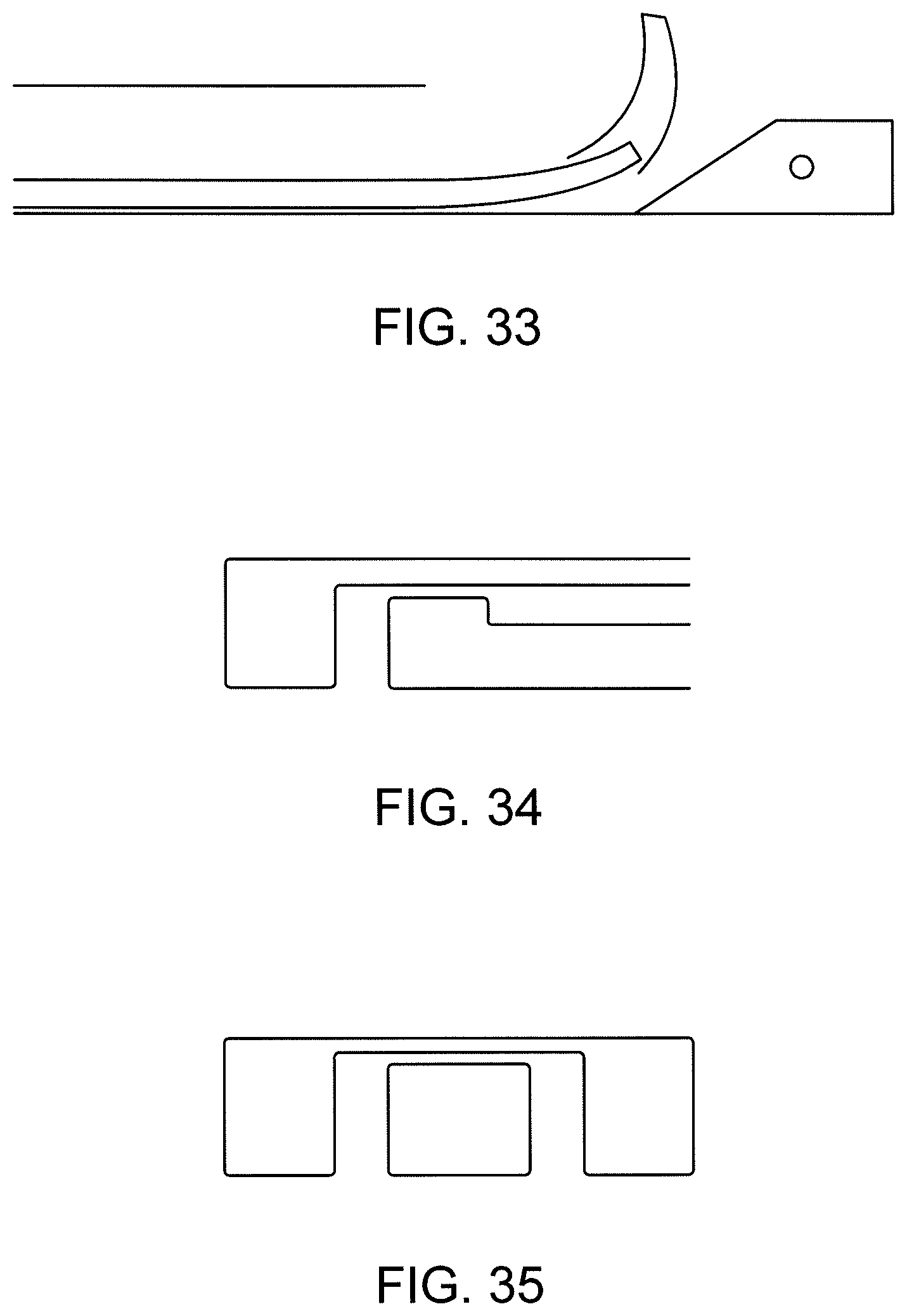
D00022

D00023

XML
uspto.report is an independent third-party trademark research tool that is not affiliated, endorsed, or sponsored by the United States Patent and Trademark Office (USPTO) or any other governmental organization. The information provided by uspto.report is based on publicly available data at the time of writing and is intended for informational purposes only.
While we strive to provide accurate and up-to-date information, we do not guarantee the accuracy, completeness, reliability, or suitability of the information displayed on this site. The use of this site is at your own risk. Any reliance you place on such information is therefore strictly at your own risk.
All official trademark data, including owner information, should be verified by visiting the official USPTO website at www.uspto.gov. This site is not intended to replace professional legal advice and should not be used as a substitute for consulting with a legal professional who is knowledgeable about trademark law.