Light sources adapted to spectral sensitivity of plant
Grajcar J
U.S. patent number 10,524,426 [Application Number 16/018,512] was granted by the patent office on 2020-01-07 for light sources adapted to spectral sensitivity of plant. This patent grant is currently assigned to SIGNIFY HOLDING B.V.. The grantee listed for this patent is SIGNIFY NORTH AMERICA CORPORATION. Invention is credited to Zdenko Grajcar.


| United States Patent | 10,524,426 |
| Grajcar | January 7, 2020 |
Light sources adapted to spectral sensitivity of plant
Abstract
A method of stimulating plant growth in a controlled environment that includes providing a lighting assembly having a network of lighting elements such as light emitting diodes (LEDs) that provide light at a color tailored for an individual plant. The lighting assembly is positioned adjacent a plant such that the light produced is received by the plant. The lighting assembly additionally has a control assembly that includes driving circuitry that modulates the lighting elements to controllably provide predetermined periods of light and dark to stimulate continuous growth of the plant.
| Inventors: | Grajcar; Zdenko (Orono, MN) | ||||||||||
|---|---|---|---|---|---|---|---|---|---|---|---|
| Applicant: |
|
||||||||||
| Assignee: | SIGNIFY HOLDING B.V.
(Eindhoven, NL) |
||||||||||
| Family ID: | 49916663 | ||||||||||
| Appl. No.: | 16/018,512 | ||||||||||
| Filed: | June 26, 2018 |
Prior Publication Data
| Document Identifier | Publication Date | |
|---|---|---|
| US 20180295787 A1 | Oct 18, 2018 | |
Related U.S. Patent Documents
| Application Number | Filing Date | Patent Number | Issue Date | ||
|---|---|---|---|---|---|
| 14413451 | |||||
| PCT/US2013/049708 | Jul 9, 2013 | ||||
| 61669825 | Jul 10, 2012 | ||||
| Current U.S. Class: | 1/1 |
| Current CPC Class: | H05B 45/10 (20200101); A01G 7/045 (20130101); Y02P 60/149 (20151101); Y02P 60/14 (20151101) |
| Current International Class: | A01G 7/04 (20060101); H05B 33/08 (20060101) |
References Cited [Referenced By]
U.S. Patent Documents
| 3529379 | September 1970 | Ware |
| 4250666 | February 1981 | Rakestraw |
| 4255897 | March 1981 | Ruthner |
| 4441145 | April 1984 | Antkowiak |
| 4914858 | April 1990 | Nijssen et al. |
| 5012609 | May 1991 | Ignatius et al. |
| 5241781 | September 1993 | Malczyk |
| 6378246 | April 2002 | DeFoor |
| 7220018 | May 2007 | Crabb et al. |
| 8074397 | December 2011 | Yoneda et al. |
| 8302346 | November 2012 | Hunt et al. |
| 8373363 | February 2013 | Grajcar |
| 8410725 | April 2013 | Jacobs |
| 8531136 | September 2013 | Grajcar |
| 8545915 | October 2013 | Schroeder |
| 8547391 | October 2013 | Marxik et al. |
| 8552942 | October 2013 | Hua |
| 8568009 | October 2013 | Chiang et al. |
| 8590207 | November 2013 | Shih |
| 8596804 | December 2013 | Grajcar |
| 8643276 | February 2014 | Maxik |
| 8643308 | February 2014 | Grajcar |
| 8651691 | February 2014 | Grajcar |
| 8656636 | February 2014 | Hunt et al. |
| 8729832 | May 2014 | Maxik et al. |
| 8738160 | May 2014 | Bucove et al. |
| 8754832 | June 2014 | Maxik et al. |
| 8760370 | June 2014 | Maxik et al. |
| 8847514 | September 2014 | Reynoso et al. |
| 8850742 | October 2014 | Dube |
| 8901584 | December 2014 | Seo et al. |
| 8901850 | December 2014 | Maxik et al. |
| 9010018 | April 2015 | Wiggins |
| 9545060 | January 2017 | Wiggins |
| 9700019 | July 2017 | Grajcar et al. |
| 10028448 | July 2018 | Grajcar et al. |
| 10070594 | September 2018 | Brusatore |
| 10212892 | February 2019 | Grajcar |
| 2003/0004556 | January 2003 | Mcdaniel |
| 2004/0065006 | April 2004 | Weder |
| 2005/0125887 | June 2005 | Taylor |
| 2005/0135104 | June 2005 | Crabb et al. |
| 2006/0113927 | June 2006 | Bondy et al. |
| 2007/0058368 | March 2007 | Partee et al. |
| 2007/0151149 | July 2007 | Karpinski |
| 2008/0302004 | December 2008 | Lin |
| 2009/0303706 | December 2009 | Atehortua |
| 2010/0020536 | January 2010 | Bafetti et al. |
| 2010/0043287 | February 2010 | Jones et al. |
| 2010/0244724 | September 2010 | Jacobs et al. |
| 2011/0001766 | January 2011 | Hua et al. |
| 2011/0101833 | May 2011 | Grajcar |
| 2011/0109244 | May 2011 | Grajcar |
| 2011/0179706 | July 2011 | Hunt et al. |
| 2011/0183368 | July 2011 | Chapman et al. |
| 2011/0193487 | August 2011 | Janik |
| 2011/0209404 | September 2011 | Scott |
| 2011/0210678 | September 2011 | Grajcar |
| 2011/0228515 | September 2011 | Grajcar |
| 2011/0241559 | October 2011 | Grajcar |
| 2011/0273098 | November 2011 | Grajcar |
| 2012/0020071 | January 2012 | Mckenzie |
| 2012/0075848 | March 2012 | Yamada et al. |
| 2012/0099305 | April 2012 | Bucove |
| 2012/0104977 | May 2012 | Mckenzie et al. |
| 2012/0170264 | July 2012 | Mckenzie et al. |
| 2012/0192486 | August 2012 | Shanahan et al. |
| 2012/0268918 | October 2012 | Grajcar |
| 2012/0287617 | November 2012 | Mekhtarian |
| 2012/0326610 | December 2012 | Lawyer et al. |
| 2013/0003382 | January 2013 | Ohura et al. |
| 2013/0006401 | January 2013 | Shan |
| 2013/0040380 | February 2013 | Hunt et al. |
| 2013/0139437 | June 2013 | Maxik |
| 2013/0172963 | July 2013 | Moffat |
| 2013/0229114 | September 2013 | Eisele et al. |
| 2013/0255145 | October 2013 | Wiggins |
| 2013/0263503 | October 2013 | Bostdorff |
| 2013/0264934 | October 2013 | Osaki et al. |
| 2013/0278445 | October 2013 | Quell et al. |
| 2013/0326941 | December 2013 | Pickett et al. |
| 2014/0069007 | March 2014 | Chen et al. |
| 2014/0123555 | May 2014 | McCord et al. |
| 2014/0152194 | June 2014 | Beyer |
| 2014/0165462 | June 2014 | Shigyo et al. |
| 2014/0250778 | September 2014 | Suntych |
| 2015/0128488 | May 2015 | Casper et al. |
| 2015/0128489 | May 2015 | Yamada et al. |
| 2015/0150195 | June 2015 | Grajcar |
| 2015/0216130 | August 2015 | Grajcar et al. |
| 2015/0273235 | October 2015 | Grajcar |
| 2016/0014974 | January 2016 | Grajcar et al. |
| 2016/0100529 | April 2016 | Grajcar |
| 2016/0109107 | April 2016 | Grajcar |
| 2016/0113213 | April 2016 | Berinsky |
| 2016/0192597 | July 2016 | Chang |
| 2016/0205739 | July 2016 | Grajcar |
| 2017/0071044 | March 2017 | Aikala |
| 2018/0295788 | October 2018 | Grajcar et al. |
| 2018/0310497 | November 2018 | Farmer |
| 2019/0082619 | March 2019 | Martin |
| 2019/0183076 | June 2019 | Muramoto |
| 2019/0246585 | August 2019 | Fyvolent |
| 1400863 | Mar 2003 | CN | |||
| 101605413 | Dec 2009 | CN | |||
| 101682953 | Mar 2010 | CN | |||
| 307991 | Mar 1989 | EP | |||
| 1626620 | Feb 2006 | EP | |||
| 2090154 | Aug 2009 | EP | |||
| 2181582 | May 2010 | EP | |||
| 2278870 | Feb 2011 | EP | |||
| 2556745 | Feb 2013 | EP | |||
| 2609362 | Jul 2013 | EP | |||
| 2785171 | Oct 2014 | EP | |||
| 2220551 | Jan 1990 | GB | |||
| 08242694 | Sep 1996 | JP | |||
| 2001128571 | May 2001 | JP | |||
| 20002199816 | Jul 2002 | JP | |||
| 2003009662 | Jan 2003 | JP | |||
| 2004113160 | Apr 2004 | JP | |||
| 2005295955 | Oct 2005 | JP | |||
| 2006262817 | Oct 2006 | JP | |||
| 2008242694 | Oct 2008 | JP | |||
| 4308891 | Aug 2009 | JP | |||
| 2009261267 | Nov 2009 | JP | |||
| 2010536156 | Nov 2010 | JP | |||
| 2011045286 | Mar 2011 | JP | |||
| 2011177127 | Sep 2011 | JP | |||
| 2011181484 | Sep 2011 | JP | |||
| 2013021981 | Feb 2013 | JP | |||
| 2013106550 | Jun 2013 | JP | |||
| 2014113145 | Jun 2014 | JP | |||
| 200621146 | Jul 2006 | TW | |||
| WO-1997030579 | Aug 1997 | WO | |||
| 2008118080 | Oct 2008 | WO | |||
| 2009022016 | Feb 2009 | WO | |||
| 2011086358 | Jul 2011 | WO | |||
| WO-2013041389 | Mar 2013 | WO | |||
| WO-2014011623 | Jan 2014 | WO | |||
| WO-2014011623 | Jan 2014 | WO | |||
| 2014085626 | Jun 2014 | WO | |||
| 2014098735 | Jun 2014 | WO | |||
| WO-2015148897 | Oct 2015 | WO | |||
| WO-2015161145 | Oct 2015 | WO | |||
| 2016014456 | Jan 2016 | WO | |||
| 2016061170 | Apr 2016 | WO | |||
| 2016115235 | Jul 2016 | WO | |||
Other References
|
"U.S. Appl. No. 14/413,451, Final Office Action dated Dec. 7, 2017", 6 pgs. cited by applicant . "U.S. Appl. No. 14/413,451, Non Final Office Action dated May 12, 2017", 8 pgs. cited by applicant . "U.S. Appl. No. 14/413,451, Notice of Allowance dated Jun. 4, 2018", 6 pgs. cited by applicant . "U.S. Appl. No. 14/413,451, Preliminary Amendment filed Jan. 19, 2015", 3 pgs. cited by applicant . "U.S. Appl. No. 14/413,451, Response filed Jan. 22, 2018 to Final Office Aciton dated Dec. 7, 2017", 6 pgs. cited by applicant . "U.S. Appl. No. 14/413,451, Response filed Jan. 27, 2017 to Restriction Requirement dated Dec. 2, 2016", 9 pgs. cited by applicant . "U.S. Appl. No. 14/413,451, Response filed Sep. 12, 2017 to Non Final Office Action dated May 12, 2017", 6 pgs. cited by applicant . "U.S. Appl. No. 14/413,451, Restriction Requirement dated Dec. 2, 2016", 7 pgs. cited by applicant . "U.S. Appl. No. 14/670,653, Final Office Action dated Dec. 22, 2016", 10 pgs. cited by applicant . "U.S. Appl. No. 14/670,653, Non Final Office Action dated May 26, 2016", 13 pgs. cited by applicant . "U.S. Appl. No. 14/670,653, Response filed Oct. 26, 2016 to Non Final Office Action dated May 26, 2016", 10 pgs. cited by applicant . "U.S. Appl. No. 14/689,117, Corrected Notice of Allowance dated May 1, 2018", 2 pgs. cited by applicant . "U.S. Appl. No. 14/689,117, Non Final Office Action dated Sep. 12, 2017", 9 pgs. cited by applicant . "U.S. Appl. No. 14/689,117, Notice of Allowance dated Mar. 29, 2018", 6 pgs. cited by applicant . "U.S. Appl. No. 14/689,117, Response filed Aug. 3, 2017 to Restriction Requirement dated Feb. 3, 2017", 5 pgs. cited by applicant . "U.S. Appl. No. 14/689,117, Response filed Dec. 12, 2017 to Non Final Office Action dated Sep. 12, 2017", 9 pgs. cited by applicant . "U.S. Appl. No. 14/689,117, Restriction Requirement dated Feb. 3, 2017", 7 pgs. cited by applicant . "Chinese Application Serial No. 201380041811, First Office Action dated Jan. 19, 2016", English Translation, 10 pgs. cited by applicant . "Chinese Application Serial No. 201380041811, Notice of Rejection dated Sep. 12, 2017", English Translation, 7 pgs. cited by applicant . "Chinese Application Serial No. 201380041811, Second Office Action dated Dec. 5, 2016", w. English Translation, 14 pgs. cited by applicant . "European Application Serial No. 13816914, search report dated Nov. 22, 2016", 17 pgs. cited by applicant . "International Application Serial No. PCT/US2013/049708, International Preliminary Report on Patentability dated Jan. 22, 2015", 7 pgs. cited by applicant . "International Application Serial No. PCT/US2013/049708, International Search Report dated Dec. 20, 2013", 2 pgs. cited by applicant . "International Application Serial No. PCT/US2013/049708, Written Opinion dated Dec. 20, 2013", 5 pgs. cited by applicant . "International Application Serial No. PCT/US2015/022939, International Preliminary Report on Patentability dated Oct. 13, 2016", 9 pgs. cited by applicant . "International Application Serial No. PCT/US2015/022939; International Search Report dated Jul. 9, 2015", 2 pgs. cited by applicant . "International Application Serial No. PCT/US2015/022939, Written Opinion dated Jul. 9, 2015", 7 pgs. cited by applicant . "International Application Serial No. PCT/US2015/026285, International Preliminary Report on Patentability dated Jul. 15, 2016", 7 pgs. cited by applicant . "International Application Serial No. PCT/US2015/026285, International Search Report dated Jul. 16, 2015", 2 pgs. cited by applicant . "International Application Serial No. PCT/US2015/026285, Written Opinion dated Jul. 16, 2015", 7 pgs. cited by applicant . "Japanese Application Serial No. 2015-521740 Notice of Rejection dated Mar. 13, 2017", 4 pgs. cited by applicant . Holick, M F, "Vitamin D: importance in the prevention of cancers, type 1 diabetes, heart disease, and osteoporosis", The American journal of clinical nutrition 79.3, (2004), 362-371. cited by applicant . "International Application Serial No. PCT US2015 041236, International Search Report dated Oct. 23, 2015", (Oct. 23, 2015), 2 pgs. cited by applicant . "International Application Serial No. PCT US2015 041236, Written Opinion dated Oct. 23, 2015", (Oct. 23, 2015), 5 pgs. cited by applicant . "International Application Serial No. PCT US2016 013224, International Search Report dated Mar. 10, 2016", (Mar. 10, 2016), 2 pgs. cited by applicant . "International Application Serial No. PCT US2016 013224, Written Opinion dated Mar. 10, 2016", (Mar. 10, 2016), 4 pgs. cited by applicant . "International Application Serial No. PCT US2015 041236, International Preliminary Report on Patentability dated Feb. 2, 2017", (Feb. 2, 2017), 7 pgs. cited by applicant . "U.S. Appl. No. 14/413,451, Corrected Notice of Allowability dated Jul. 3, 2018", 2 pgs. cited by applicant . "U.S. Appl. No. 16/018,556, Preliminary Amendment filed Jul. 16, 2018", 5 pgs. cited by applicant . Roach, "Regulation of Photosynthetic Electron Transport and Photoinhibition", Current Protein and Peptide Science, vol. 15, No. 4, (Apr. 28, 2014), 20 pgs. cited by applicant. |
Primary Examiner: Hayes; Kristen C
Parent Case Text
CROSS REFERENCE
This application claims benefit to and is based upon U.S. Provisional Patent Application Ser. No. 61/669,825 filed Jul. 10, 2012 titled "Light Sources Adapted to Spectral Sensitivity of Plant" and that application is incorporated by reference in full.
Claims
What is claimed is:
1. A method of stimulating plant growth in a controlled environment comprising: providing a cylindrical body having at least one plant disposed therein; placing a network of lighting elements that produce light at a predetermined wavelength arcuately around the periphery of the cylindrical body adjacent to the plant in order to provide light to the at least one plant; and rotating the cylindrical body at a predetermined speed relative to the lighting elements to controllably provide predetermined periods of light and dark to stimulate continuous growth of the plant.
2. The method of claim 1 wherein the network of lighting elements includes light emitting diodes (LEDs).
3. The method of claim 1 wherein the predetermined wavelength of the light is in a range including and between 350 nanometers (nm) to 500 nm.
4. The method of claim 3 wherein the network of lighting elements includes a second network of lighting elements that produce light at a predetermined wavelength that are LEDs in series with the light emitting diodes.
5. The method of claim 4 wherein the predetermined wavelength of the second network of lighting elements is in a range between 600 nm and 750 nm.
6. The method of claim 1 wherein the predetermined wavelength of the light is in a range including and between 600 nm and 750 nm.
7. The method of claim 1 wherein the predetermined periods of light are in a range between zero and 30 minutes and the predetermined periods of dark are in a range between zero and 30 minutes.
8. The method of claim 1 where in the network of lighting elements arcuately surround 180 degrees of the cylindrical body.
9. The method of claim 1 where in the network of lighting elements arcuately surround 90 degrees of the cylindrical body.
10. The method of claim 1 wherein the body controllably presents a shield between the lighting elements and the at least one plant to provide the predetermined period of dark.
Description
BACKGROUND
This invention relates to plant growth. More specifically this invention relates to a method and assembly of radiating plants to enhance photosynthesis.
It is well known in the art that during the photosynthesis process plants absorb different frequencies of light to cause photosynthesis to occur. In particular photosynthetically active radiation (PAR) is radiation in the spectral range from approximately 400 nanometers (nm) to 700 nm. Also known in the art is that chlorophyll, the most abundant plant pigment and the pigment responsible for plant metabolism is most efficient at capturing red and blue light.
During photosynthesis the chlorophyll pigments in a plant absorb photons in order to drive a metabolic process and dissipate other energy within the photons. Simultaneously other pigments that are red/farred and blue/UV-A and UV-B photosensors or photoreceptors chemically react to adjust the behavior and development of the plant. Thus, by providing red and blue spectrum light, plants have been shown to grow at increased rates.
In addition, also known in the art is that plants need turn over, or time in the dark. In particular, when a pigment has accepted a photon and is going through the metabolic process, the pigment cannot accept additional photons. Still, when additional photons bombard the plant the pigments will continue to attempt to metabolize thus straining or fatiguing the plant. Thus dark time is needed to allow the pigments to complete the metabolic process and to restart the process. Thus just as humans need sleep, plants similarly need down time to optimize the metabolic process. In particular, depending on the type of plant, a plant needs approximately 3.5 to 14.5 milliseconds (ms) of turn over time per every 24 ms in order to minimize the fatigue or strain caused by the light.
As a result of this phenomena, DC lighting that is controlled by pulse width modulation (PWM) has been utilized in order to enhance the growth characteristics in plants. By utilizing PWM lighting in bursts or flicker not detectable by the human eye those in the art have attempted to optimize photosynthesis.
Still, problems exist as a result of utilizing DC lighting. Specifically DC (direct current) lighting is expensive, can be unreliable and difficult to use. In addition, while research on these effects has been conducted, industry applicable products that are easy to use and meaningful are still desired. Thus, a need in the art exists for an AC (alternating current) lighting source that is robust, inexpensive to manufacture and operate and is able to enhance growth characteristics in plants.
Therefore, a principle object of the present invention is to enhance growth characteristics in plants utilizing an AC power source.
Another object of the present invention is to provide cost effective lighting that enhances plant growth.
Yet another object of the present invention is to provide a lighting assembly that is used for multiple plants.
Another object of the present invention is to provide alternative methods of modulating light provided to plants to use of a DC power source.
These and other objects, features and advantages will become apparent from the rest of the specification.
SUMMARY OF THE INVENTION
A horticultural assembly for the growth of plants, including flowers. The assembly includes AC powered light source assemblies adjacent plants and adapted to the spectral sensitivity of plants. A light engine assembly is provided that is dimmable and through phase cutting can stop current from going to LEDs in the assembly to provide periods where no light is being emitted by the assembly. Further the light engine assembly includes a chip element that provides both red and blue light emitting diodes (LEDs) in series such that through phase cutting red and blue light emissions can be controlled.
BRIEF DESCRIPTION OF THE DRAWINGS
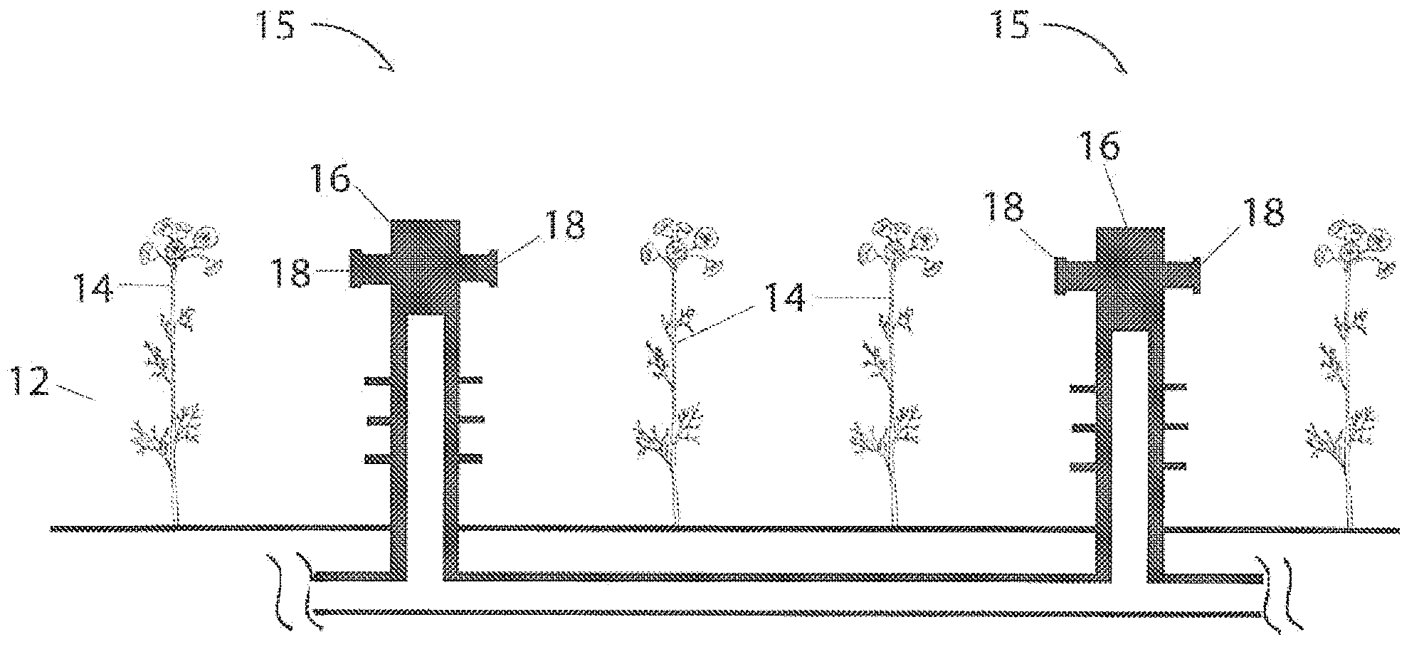
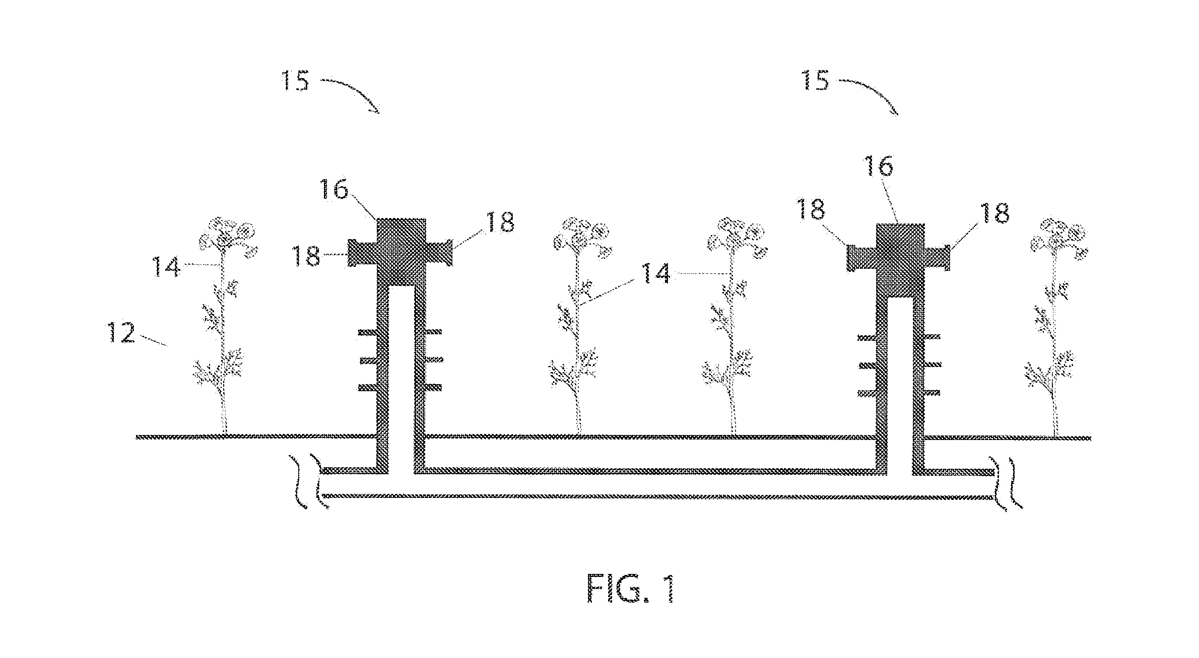
FIG. 1 is a side plan view of a lighting assembly in a controlled environment for growing plant life;
FIG. 2 is a schematic diagram of a lighting assembly for growing plant life;
FIG. 3 is a schematic diagram of circuitry within a lighting assembly for growing plant life;
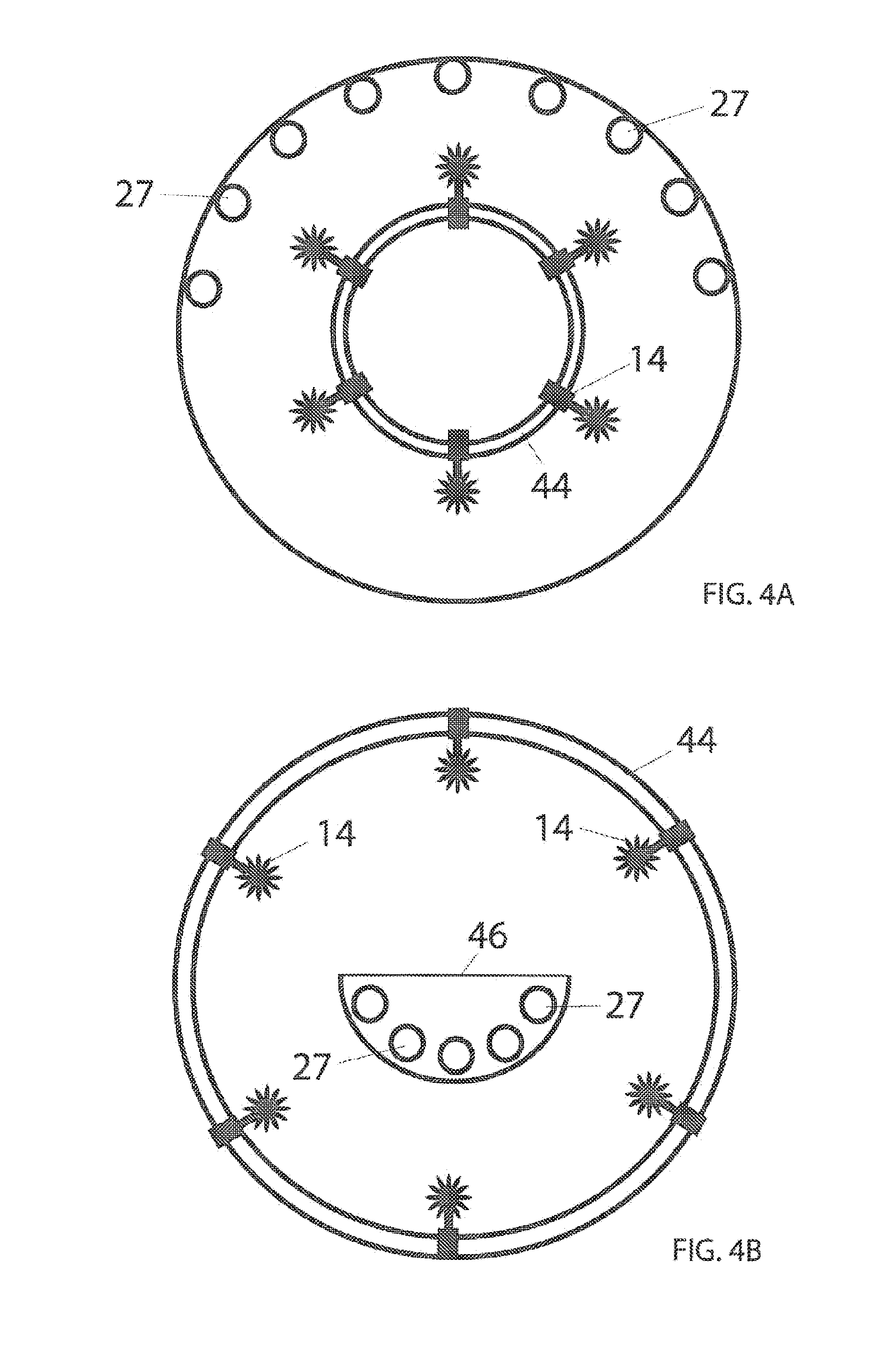
FIG. 4A is a side plan view of a cylindrical body for growing plant life;
FIG. 4B is a side plan view of a cylindrical body for growing plant life;
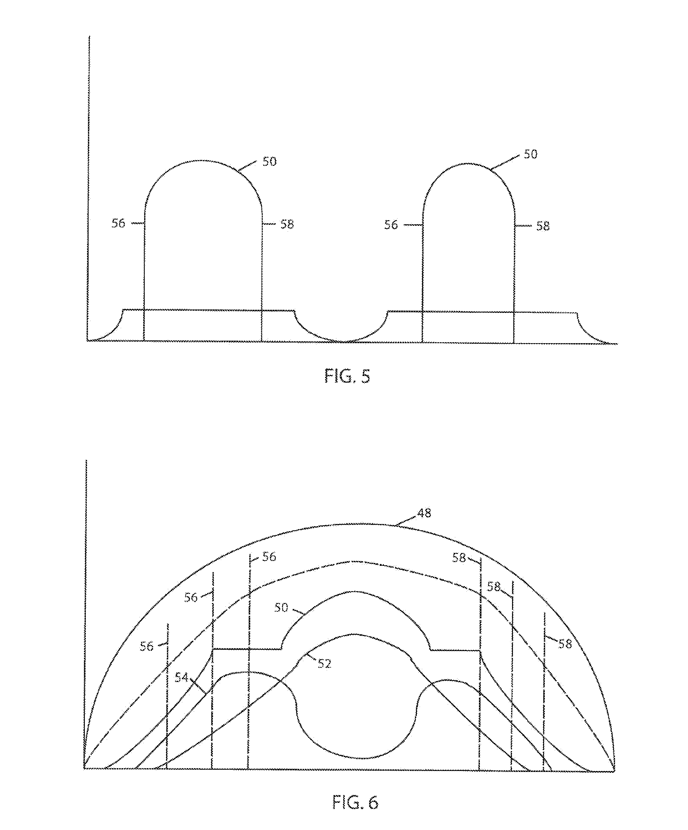
FIG. 5 is a graph showing voltage and current over a period of time for a lighting assembly for growing plant life; and
FIG. 6 is a graph showing voltage and current over a period of time for a lighting assembly for growing plant life.
DETAILED DESCRIPTION OF A PREFERRED EMBODIMENT
As shown in FIG. 1 a horticultural assembly 10 can be at any location, including outdoors, in a green house, indoors or the like. The assembly 10 includes a container or space 12 where plants 14 that are typically planted in side by side relation are located. While described as being planted in side by side relation, a single plant, or plurality of plants planted in any relation to one another is contemplated and does not fall outside of this disclosure. A water system 15 is also provided that preferably comprises a series of water conduits 16 that convey water to the plants 14 to assist in the growing process.
Positioned adjacent the plants are a plurality of light source assemblies 18 powered by an AC source. These assemblies 18 may be mounted or secured to the water conduits 16 of the water conduit system 14 or alternatively placed on a secondary conduit system or otherwise placed or mounted adjacent the plants 14 such that at least one plant receives radiation emitted by the assemblies 18.
The assemblies 18 are dimmable and are constructed as is described in U.S. patent application Ser. No. 12/824,215 to Grajcar and/or U.S. patent application Ser. No. 12/914,575 to Grajcar, both that are incorporated herein. One such assembly as an example only is shown in FIG. 2 having an pair of input terminals 20 that are adapted to receive a periodic excitation voltage such that the terminals can receive AC current or a current of equal magnitude and opposite polarity, said current flowing in response to the excitation voltage to provide an AC input. The AC current is then conditioned by driving circuitry 22 that optionally includes an metal oxide varesistor (MOV) 24 and a rectifying device 25 that in a preferred embodiment is a bridge rectifier formed of a plurality of light emitting diodes (LEDs) 26.
A plurality of lighting elements 27 such as light emitting diodes (LEDs) 26 are arranged in a first network 28 where the first network 28 is arranged to conduct the current in response to the excitation voltage exceeding at least a forward threshold voltage associated with the first network 28. Optionally depending on the driving circuitry 22 a resistor 30 or multiple resistors can be used to condition the current before reaching the first network 28. The LEDs 26 of the first network 28 can be of any type or color. In one embodiment the LEDs 26 of the first network 28 are red LEDs that produce light having a wavelength of approximately 600-750 nano meters (nm). In another embodiment the first network of LEDs are blue LEDs that produce light having a wavelength of approximately 350-500 nm. Alternatively both red and blue LEDs can be provided together or other colored LEDs such as green may similarly be used without falling outside the scope of this disclosure.
A second network 32 having lighting elements 27 such as a plurality of LEDs 26 is additionally provided in series relationship with the first network 28. The LEDs 26 of the second network 32 can be of any type or color. In one embodiment the LEDs 26 of the second network 32 are red LEDs that produce light having a wavelength of approximately 600-750 nano meters (nm). In another embodiment the second network of LEDs are blue LEDs that produce light having a wavelength of approximately 350-500 nm. Alternatively both red and blue LEDs can be provided together or other colored LEDs such as green may similarly be used without falling outside the scope of this disclosure.
A bypass path 34 is provided in the assembly 18 that is in series relationship with the first network 28 and in parallel relationship with the second network 32. Also within the bypass path 34 are elements that provide a controlled impedance, which can be, for example only a transistor 36 that in one embodiment is a depletion MOSFET. Additional transistors, resistors or the like can be used within the bypass path 34 all that condition current to provide the smooth and continuous transition from the bypass path 34 to the second network 32.
Accordingly, it is appreciated from the disclosure herein that color temperature shifting as a function of input excitation waveforms may be implemented or designed based on appropriate selection of LED groups or networks 28 and 32 and arrangement of one or more selective current diversion conditioning circuits to modulate a bypass current around selected LED networks 28 and 32. The selection of the number of diodes in each group, excitation voltage, phase control range, diode colors, and peak intensity parameters may be manipulated to yield improved electrical and/or light output performance for a range of lighting applications.
FIGS. 3 and 4A and 4B show manners in which modulation of light is provided that does not require utilization of a DC power source. In one embodiment as shown in FIG. 3 a control assembly 38 is provided. The control assembly 38 can be a dimming device utilizing power leading edge and falling edge phase cutting elements. As an example only a triac dimmer presents phase cutting at a leading edge while a IGBT dimmer presents phase cutting at a trailing edge. In this embodiment the dimming device having both leading edge and trailing edge phase cutting is in electrical communication with the driving circuitry 22. In this manner by utilizing both in a control assembly 38 a predetermined period of no current is provided. Thus a control device 40 associated with the control assembly 38 can be used to determine the period of no current and thus period of dark.
In another embodiment the control assembly 38 includes at least one SCR silicon controlled rectifier) and in one embodiment first and second SCRs that are utilized to cut current provided for a predetermined period of time. The cut can occur at a 0 phase angle or alternatively at an angle. Thus, by utilizing SCRs, the control assembly 38 again functions as a controllable on/off switch of the lighting assemblies 18. Specifically, in one embodiment the control device 40, such as a control knob is in communication with first and second SCRs such that the predetermined period of light and dark can be set at any predetermined time period from 0-30 minutes.
In an alternative embodiment as provided in FIGS. 4A and 4B the modulation of light is not controlled electrically. In opposite either the lighting assemblies 18 themselves or the plants 14 move relative to one another to cause periods of light and dark to occur. In one embodiment a plurality of plants 14 are disposed within a rotating cylindrical body 44 that in one embodiment is a barrel with a plurality of lighting elements 27 arcuately surrounding the periphery 46 of the cylindrical body 44 adjacent the plants 14. In one embodiment approximately 180.degree. of lighting elements 27 arcuately surround the cylindrical body. In another embodiment only 90.degree. of lighting elements 27 are provided. In this manner the cylindrical body 44 can rotate, the lighting elements 27 can rotate or both can rotate to create periods of light and dark. In particular the lighting elements can have a low diffusion rate thus providing only direct light ensuring a dark period occurs. Therefore, the length of the periods of light and dark can be controlled by the relative rotational speed between the lighting elements 27 and plants 14 in the cylindrical body 44. Alternatively a shield 46 can be presented to block light again causing dark periods to occur.
FIGS. 5 and 6 show graphs of voltage and current in a possible embodiment utilizing red and blue lighting elements 27 and a control assembly 38 for controlling modulation of light. In this embodiment the driving circuitry 22 in response to the input voltage 48 conditions the overall current 50. In this manner blue lighting element current 52 steadily increases then decreases while red lighting element current 54 increases, then decreases before again increasing. Depending on the requirements of a user the current 50 can optionally be cut at a leading edge 56 and trailing edge 58 as desired to reduce current to zero and create a period of darkness as discussed in detail above. Therefore, depending on the driving circuitry 22 and choice of lighting elements 27 as used in association with the lighting elements 27 the color output of the lighting assembly 18 is controllable so that once the optimum lighting for a given plant is determined, the assembly 18 can be controlled to provide this optimum result. In this manner both the optimum spectrum and modulation of light can be provided.
In operation, one can study and determine the predetermined light and dark period for a specific plant, along with predetermined light wavelengths or colors for a plant that optimizes a characteristic of the plant, such as growth, yield or the like. Then a lighting assembly 18 is manufactured to present the predetermined light wavelength and the control assembly 38 can be adjusted to provide the optimum predetermined light and dark periods for optimum growth.
The light assemblies 18 are constructed to present a phase of a predetermined time duration depending on the modulation of the conditioned current provided to the lighting elements 27. In a preferred embodiment the phase is 24 ms. During this phase as a result of phase cutting, whether leading edge by a triac or other component and/or falling edge by a transistor such as a IGBT or the like, current is not supplied to LEDs for a predetermined amount of time or period, preferably between 3.5 to 14.5 ms during each 24 ms phase to create a dark or turnover period for 3.5 to 14.5 ms. During this 3.5 to 14.5 ms the plants 14 experience turnover time in order to optimize the photosynthesis process. Specifically thus provided are predetermined periods of light and dark that stimulate continuous growth of the plant. When used in the context of this application, predetermined periods of light and dark are measured or determined by what can be perceived by a plant 14 and represents periods when no light is being emitting by the lighting elements 27, even if the light or dark cannot be perceived by a human. Thus, flicker and unperceivable flicker present that is not perceived by humans is considered to provide a predetermined period of light and dark within the context of this disclosure.
In the embodiment where first and second SCRs are utilized the SCRs function as a controllable on/off switch of the lighting assemblies 18. Such functioning allows for a predetermined period of light and a predetermined period of dark. In one embodiment the predetermined period for both the light and dark is approximately 30 minutes. Specifically the control assembly 38 is in communication with the first and second SCRs such that the predetermined period of light and dark can be set at any predetermined time period from 0-30 minutes. In this manner one can control the pre-determined durations of light and dark to match the optimum requirements of specific plants.
Thus presented is a method and assembly 10 for illuminating a plurality of plants 14. The assembly 10 includes an AC powered light assembly 18 that through phase cutting provides a lighting cycle or phase that includes a predetermined amount of dark or turnover time for the plant. As a result the plant 14 gets the needed rest to relieve plant stress and strain during the completion of the metabolizing process. At this point the plant 14 is then ready to absorb more light to continue metabolizing in the photosynthesis process.
Meanwhile, by having red and blue diodes the effectiveness of the metabolizing and photosynthesis is maximized. Specifically red LEDs and blue LEDs can comprise the different networks 28 and 32 of LEDs to create intermittent blue light and red light in order to optimize the light received by the plants 14 according to the ideal PAR for that particular plant 14. As a result, not only can you have a 24 hour constant light growing cycle, but in addition the growth of the plant in maximized. The result is faster maturation and larger yield for the plats.
In addition, the control assembly 38 allows an individual to control the modulation of light for specific plants 14. Thus, if the optimum growing condition is to provide a period of 3.5 ms of light and 3.5 ms of dark, the control assembly 38 can be adjusted to provide this modulation. If a period of 30 minutes instead is required for maximum plant growth and enhancement of photosynthesis, the control device 42 can be adjusted and the assembly 18 can provide the modulation required. In this manner the assembly 18 can be used for numerous varieties of plants 14 without the need for a different assembly to be manufactured, thus improving on the state of the art.
In addition the lighting assemblies are easily manufactured and incorporated into new and existing horticulture assemblies by mounting or attaching them to water conduits 16 or mounting them otherwise adjacent to the plants 14. Finally, because current is conditioned from an AC input is utilized and pulse width modulation eliminated, the cost associated with the lighting assembly 18 is greatly reduced. Thus, at the very least all of the stated objects have been met.
* * * * *
D00000
D00001
D00002
D00003
D00004
D00005
XML
uspto.report is an independent third-party trademark research tool that is not affiliated, endorsed, or sponsored by the United States Patent and Trademark Office (USPTO) or any other governmental organization. The information provided by uspto.report is based on publicly available data at the time of writing and is intended for informational purposes only.
While we strive to provide accurate and up-to-date information, we do not guarantee the accuracy, completeness, reliability, or suitability of the information displayed on this site. The use of this site is at your own risk. Any reliance you place on such information is therefore strictly at your own risk.
All official trademark data, including owner information, should be verified by visiting the official USPTO website at www.uspto.gov. This site is not intended to replace professional legal advice and should not be used as a substitute for consulting with a legal professional who is knowledgeable about trademark law.