Heat exchanger assembly for an electronic display
Dunn , et al. Dec
U.S. patent number 10,524,397 [Application Number 15/589,932] was granted by the patent office on 2019-12-31 for heat exchanger assembly for an electronic display. This patent grant is currently assigned to Manufacturing Resources International, Inc.. The grantee listed for this patent is Manufacturing Resources International, Inc.. Invention is credited to William Dunn, Tim Hubbard, Kevin O'Connor.


| United States Patent | 10,524,397 |
| Dunn , et al. | December 31, 2019 |
Heat exchanger assembly for an electronic display
Abstract
The exemplary embodiments disclosed herein are directed to a heat exchanger assembly for cooling power module bricks, the heat exchanger assembly having a plurality of spaced apart heat exchanger layers between which external air and a closed loop gas are separately circulated. A series of metallic plates may be located within the spaces between some or all of the heat exchanger layers to conduct heat from the power modules. Circulating fans may be employed to circulate external air and circulating gas through the heat exchanger. Pass through junctions may be positioned near edges of the heat exchanger to permit the circulating gas to cross paths with the external air without allowing the two gas flows to mix with one another.
| Inventors: | Dunn; William (Alpharetta, GA), Hubbard; Tim (Alpharetta, GA), O'Connor; Kevin (Duluth, GA) | ||||||||||
|---|---|---|---|---|---|---|---|---|---|---|---|
| Applicant: |
|
||||||||||
| Assignee: | Manufacturing Resources
International, Inc. (Alpharetta, GA) |
||||||||||
| Family ID: | 51580653 | ||||||||||
| Appl. No.: | 15/589,932 | ||||||||||
| Filed: | May 8, 2017 |
Prior Publication Data
| Document Identifier | Publication Date | |
|---|---|---|
| US 20170245400 A1 | Aug 24, 2017 | |
Related U.S. Patent Documents
| Application Number | Filing Date | Patent Number | Issue Date | ||
|---|---|---|---|---|---|
| 14198141 | Mar 5, 2014 | 9648790 | |||
| 61791421 | Mar 15, 2013 | ||||
| Current U.S. Class: | 1/1 |
| Current CPC Class: | H05K 7/20145 (20130101); G11B 33/06 (20130101); H05K 7/20972 (20130101); H05K 7/20909 (20130101); H05K 7/202 (20130101); H05K 7/209 (20130101); H05K 7/20 (20130101) |
| Current International Class: | H05K 7/20 (20060101); G11B 33/06 (20060101) |
| Field of Search: | ;361/695 |
References Cited [Referenced By]
U.S. Patent Documents
| 4093355 | June 1978 | Kaplit et al. |
| 4593978 | June 1986 | Mourey et al. |
| 4634225 | January 1987 | Haim et al. |
| 4748765 | June 1988 | Martin |
| 4763993 | August 1988 | Vogeley et al. |
| 4921041 | May 1990 | Akachi |
| 4952783 | August 1990 | Aufderheide et al. |
| 4952925 | August 1990 | Haastert |
| 5029982 | July 1991 | Nash |
| 5088806 | February 1992 | McCartney et al. |
| 5247374 | September 1993 | Terada |
| 5282114 | January 1994 | Stone |
| 5293930 | March 1994 | Pitasi |
| 5432526 | July 1995 | Hyatt |
| 5535816 | July 1996 | Ishida |
| 5559614 | September 1996 | Urbish et al. |
| 5621614 | April 1997 | O'Neill |
| 5657641 | August 1997 | Cunningham et al. |
| 5748269 | May 1998 | Harris et al. |
| 5765743 | June 1998 | Sakiura et al. |
| 5767489 | June 1998 | Ferrier |
| 5808418 | September 1998 | Pitman et al. |
| 5818010 | October 1998 | McCann |
| 5818694 | October 1998 | Daikoku et al. |
| 5835179 | November 1998 | Yamanaka |
| 5864465 | January 1999 | Liu |
| 5869818 | February 1999 | Kim |
| 5869919 | February 1999 | Sato et al. |
| 5903433 | May 1999 | Gudmundsson |
| 5991153 | November 1999 | Heady et al. |
| 6003015 | December 1999 | Kang et al. |
| 6007205 | December 1999 | Fujimori |
| 6043979 | March 2000 | Shim |
| 6089751 | July 2000 | Conover et al. |
| 6104451 | August 2000 | Matsuoka et al. |
| 6157432 | December 2000 | Helbing |
| 6181070 | January 2001 | Dunn et al. |
| 6191839 | February 2001 | Briley et al. |
| 6198222 | March 2001 | Chang |
| 6211934 | April 2001 | Habing et al. |
| 6215655 | April 2001 | Heady et al. |
| 6351381 | February 2002 | Bilski et al. |
| 6392727 | May 2002 | Larson et al. |
| 6417900 | July 2002 | Shin et al. |
| 6428198 | August 2002 | Saccomanno et al. |
| 6473150 | October 2002 | Takushima et al. |
| 6476883 | November 2002 | Salimes et al. |
| 6493440 | December 2002 | Gromatsky et al. |
| 6504713 | January 2003 | Pandolfi et al. |
| 6535266 | March 2003 | Nemeth et al. |
| 6628355 | September 2003 | Takahara |
| 6701143 | March 2004 | Dukach et al. |
| 6714410 | March 2004 | Wellhofer |
| 6727468 | April 2004 | Nemeth |
| 6742583 | June 2004 | Tikka |
| 6812851 | November 2004 | Dukach et al. |
| 6825828 | November 2004 | Burke et al. |
| 6839104 | January 2005 | Taniguchi et al. |
| 6850209 | February 2005 | Mankins et al. |
| 6885412 | April 2005 | Ohnishi et al. |
| 6886942 | May 2005 | Okada et al. |
| 6891135 | May 2005 | Pala et al. |
| 6909486 | June 2005 | Wang et al. |
| 6943768 | September 2005 | Cavanaugh et al. |
| 6961108 | November 2005 | Wang et al. |
| 7015470 | March 2006 | Faytlin et al. |
| 7059757 | June 2006 | Shimizu |
| 7083285 | August 2006 | Hsu et al. |
| 7157838 | January 2007 | Thielemans et al. |
| 7161803 | January 2007 | Heady |
| 7190587 | March 2007 | Kim et al. |
| 7209349 | April 2007 | Chien et al. |
| 7212403 | May 2007 | Rockenfell |
| 7259964 | August 2007 | Yamamura et al. |
| 7269023 | September 2007 | Nagano |
| 7284874 | October 2007 | Jeong et al. |
| 7452121 | November 2008 | Cho et al. |
| 7457113 | November 2008 | Kumhyr et al. |
| 7480140 | January 2009 | Hara et al. |
| 7535543 | May 2009 | Dewa et al. |
| 7591508 | September 2009 | Chang |
| 7602469 | October 2009 | Shin |
| D608775 | January 2010 | Leung |
| 7667964 | February 2010 | Kang et al. |
| 7682047 | March 2010 | Hsu et al. |
| 7752858 | July 2010 | Johnson et al. |
| 7753567 | July 2010 | Kang et al. |
| 7762707 | July 2010 | Kim et al. |
| 7800706 | September 2010 | Kim et al. |
| 7813124 | October 2010 | Karppanen |
| 7903416 | March 2011 | Chou |
| 7995342 | August 2011 | Nakamichi et al. |
| 8004648 | August 2011 | Dunn |
| 8035968 | October 2011 | Kwon et al. |
| 8081465 | December 2011 | Nishiura |
| 8102173 | January 2012 | Merrow |
| 8142027 | March 2012 | Sakai |
| 8208115 | June 2012 | Dunn |
| 8223311 | July 2012 | Kim et al. |
| 8241573 | August 2012 | Banerjee et al. |
| 8248784 | August 2012 | Nakamichi et al. |
| 8254121 | August 2012 | Lee et al. |
| 8269916 | September 2012 | Ohkawa |
| 8270163 | September 2012 | Nakamichi et al. |
| 8274622 | September 2012 | Dunn |
| 8274789 | September 2012 | Nakamichi et al. |
| 8300203 | October 2012 | Nakamichi et al. |
| 8320119 | November 2012 | Isoshima et al. |
| 8351014 | January 2013 | Dunn |
| 8358397 | January 2013 | Dunn |
| 8369083 | February 2013 | Dunn et al. |
| 8373841 | February 2013 | Dunn |
| 8379182 | February 2013 | Dunn |
| 8400608 | March 2013 | Takahashi et al. |
| 8472174 | June 2013 | Idems et al. |
| 8472191 | June 2013 | Yamamoto et al. |
| 8482695 | July 2013 | Dunn |
| 8497972 | July 2013 | Dunn et al. |
| 8590602 | November 2013 | Fernandez |
| 8649170 | February 2014 | Dunn et al. |
| 8649176 | February 2014 | Okada et al. |
| 8654302 | February 2014 | Dunn et al. |
| 8678603 | March 2014 | Zhang |
| 8693185 | April 2014 | Dunn et al. |
| 8700226 | April 2014 | Schuch et al. |
| 8711321 | April 2014 | Dunn et al. |
| 8749749 | June 2014 | Hubbard |
| 8755021 | June 2014 | Hubbard |
| 8758144 | June 2014 | Williams et al. |
| 8760613 | June 2014 | Dunn |
| 8767165 | July 2014 | Dunn |
| 8773633 | July 2014 | Dunn et al. |
| 8804091 | August 2014 | Dunn et al. |
| 8823916 | September 2014 | Hubbard et al. |
| 8854572 | October 2014 | Dunn |
| 8854595 | October 2014 | Dunn |
| 8879042 | November 2014 | Dunn |
| 8988647 | March 2015 | Hubbard |
| 9030641 | May 2015 | Dunn |
| 9089079 | July 2015 | Dunn |
| 9119325 | August 2015 | Dunn et al. |
| 9119330 | August 2015 | Hubbard et al. |
| 9173322 | October 2015 | Dunn |
| 9173325 | October 2015 | Dunn |
| 9282676 | March 2016 | Diaz |
| 9285108 | March 2016 | Dunn et al. |
| 9313917 | April 2016 | Dunn et al. |
| 9370127 | June 2016 | Dunn |
| 9448569 | September 2016 | Schuch et al. |
| 9451060 | September 2016 | Bowers et al. |
| 9451733 | September 2016 | Dunn et al. |
| 9456525 | September 2016 | Yoon et al. |
| 9470924 | October 2016 | Dunn et al. |
| 9500896 | November 2016 | Dunn et al. |
| 9516485 | December 2016 | Bowers et al. |
| 9549490 | January 2017 | Hubbard |
| 9594271 | March 2017 | Dunn et al. |
| 9613548 | April 2017 | DeMars |
| 9622392 | April 2017 | Bowers et al. |
| 9629287 | April 2017 | Dunn |
| 9648790 | May 2017 | Dunn |
| 9655289 | May 2017 | Dunn et al. |
| 9723765 | August 2017 | DeMars |
| 9894800 | February 2018 | Dunn |
| 2001/0001459 | May 2001 | Savant et al. |
| 2001/0019454 | September 2001 | Tadic-Galeb et al. |
| 2002/0009978 | January 2002 | Dukach et al. |
| 2002/0033919 | March 2002 | Sanelle et al. |
| 2002/0065046 | May 2002 | Mankins et al. |
| 2002/0084891 | July 2002 | Mankins et al. |
| 2002/0101553 | August 2002 | Enomoto et al. |
| 2002/0126248 | September 2002 | Yoshia |
| 2002/0148600 | October 2002 | Bosch et al. |
| 2002/0149714 | October 2002 | Anderson et al. |
| 2002/0154255 | October 2002 | Gromatzky et al. |
| 2002/0164944 | November 2002 | Haglid |
| 2002/0164962 | November 2002 | Mankins et al. |
| 2002/0167637 | November 2002 | Burke et al. |
| 2003/0007109 | January 2003 | Park |
| 2003/0020884 | January 2003 | Okada et al. |
| 2003/0043091 | March 2003 | Takeuchi et al. |
| 2003/0104210 | June 2003 | Azumi et al. |
| 2003/0128511 | July 2003 | Nagashima et al. |
| 2003/0214785 | November 2003 | Perazzo |
| 2004/0012722 | January 2004 | Alvarez |
| 2004/0035558 | February 2004 | Todd et al. |
| 2004/0036834 | February 2004 | Ohnishi et al. |
| 2004/0042174 | March 2004 | Tomioka et al. |
| 2004/0103570 | June 2004 | Ruttenberg |
| 2004/0105159 | June 2004 | Saccomanno et al. |
| 2004/0165139 | August 2004 | Anderson et al. |
| 2004/0223299 | November 2004 | Ghosh |
| 2005/0012039 | January 2005 | Faytlin et al. |
| 2005/0012722 | January 2005 | Chon |
| 2005/0062373 | March 2005 | Kim et al. |
| 2005/0073632 | April 2005 | Dunn et al. |
| 2005/0073639 | April 2005 | Pan |
| 2005/0127796 | June 2005 | Olesen et al. |
| 2005/0134525 | June 2005 | Tanghe et al. |
| 2005/0134526 | June 2005 | Willem et al. |
| 2005/0213950 | September 2005 | Yoshimura |
| 2005/0229630 | October 2005 | Richter et al. |
| 2005/0237714 | October 2005 | Ebermann |
| 2005/0276053 | December 2005 | Nortrup et al. |
| 2005/0286131 | December 2005 | Saxena et al. |
| 2006/0012958 | January 2006 | Tomioka et al. |
| 2006/0018093 | January 2006 | Lai et al. |
| 2006/0034051 | February 2006 | Wang et al. |
| 2006/0056994 | March 2006 | Van Lear et al. |
| 2006/0082271 | April 2006 | Lee et al. |
| 2006/0092348 | May 2006 | Park |
| 2006/0125998 | June 2006 | Dewa et al. |
| 2006/0132699 | June 2006 | Cho et al. |
| 2006/0177587 | August 2006 | Ishizuka et al. |
| 2006/0199514 | September 2006 | Kimura |
| 2006/0209266 | September 2006 | Utsunomiya |
| 2006/0260790 | November 2006 | Theno et al. |
| 2006/0262079 | November 2006 | Seong et al. |
| 2006/0266499 | November 2006 | Choi et al. |
| 2006/0283579 | December 2006 | Ghosh et al. |
| 2007/0019419 | January 2007 | Hafuka et al. |
| 2007/0030879 | February 2007 | Hatta |
| 2007/0047239 | March 2007 | Kang et al. |
| 2007/0065091 | March 2007 | Hinata et al. |
| 2007/0076431 | April 2007 | Atarashi et al. |
| 2007/0081344 | April 2007 | Cappaert et al. |
| 2007/0103863 | May 2007 | Kim |
| 2007/0103866 | May 2007 | Park |
| 2007/0115686 | May 2007 | Tyberghien |
| 2007/0139929 | June 2007 | Yoo et al. |
| 2007/0140671 | June 2007 | Yoshimura |
| 2007/0151274 | July 2007 | Roche et al. |
| 2007/0151664 | July 2007 | Shin |
| 2007/0171353 | July 2007 | Hong |
| 2007/0206158 | September 2007 | Kinoshita et al. |
| 2007/0211205 | September 2007 | Shibata |
| 2007/0212211 | September 2007 | Chiyoda et al. |
| 2007/0217221 | September 2007 | Lee et al. |
| 2007/0237636 | October 2007 | Hsu |
| 2007/0267174 | November 2007 | Kim |
| 2008/0055534 | March 2008 | Kawano |
| 2008/0076342 | March 2008 | Bryant et al. |
| 2008/0099193 | May 2008 | Aksamit et al. |
| 2008/0148609 | June 2008 | Ogoreve |
| 2008/0209934 | September 2008 | Richards |
| 2008/0218446 | September 2008 | Yamanaka |
| 2008/0236005 | October 2008 | Isayev et al. |
| 2008/0267790 | October 2008 | Gaudet et al. |
| 2008/0283234 | November 2008 | Sagi et al. |
| 2008/0285290 | November 2008 | Ohashi et al. |
| 2009/0009047 | January 2009 | Yanagawa et al. |
| 2009/0009729 | January 2009 | Sakai |
| 2009/0059518 | March 2009 | Kakikawa et al. |
| 2009/0086430 | April 2009 | Kang et al. |
| 2009/0120629 | May 2009 | Ashe |
| 2009/0122218 | May 2009 | Oh et al. |
| 2009/0126906 | May 2009 | Dunn |
| 2009/0126907 | May 2009 | Dunn |
| 2009/0126914 | May 2009 | Dunn |
| 2009/0135365 | May 2009 | Dunn |
| 2009/0147170 | June 2009 | Oh et al. |
| 2009/0154096 | June 2009 | Iyengar et al. |
| 2009/0174626 | July 2009 | Isoshima et al. |
| 2009/0231807 | September 2009 | Bouissier |
| 2009/0244472 | October 2009 | Dunn |
| 2009/0279240 | November 2009 | Karppanen |
| 2009/0302727 | December 2009 | Vincent et al. |
| 2009/0306820 | December 2009 | Simmons et al. |
| 2010/0060861 | March 2010 | Medin |
| 2010/0079949 | April 2010 | Nakamichi et al. |
| 2010/0162747 | July 2010 | Hamel et al. |
| 2010/0171889 | July 2010 | Pantel et al. |
| 2010/0182562 | July 2010 | Yoshida et al. |
| 2010/0220249 | September 2010 | Nakamichi et al. |
| 2010/0226091 | September 2010 | Dunn |
| 2010/0232107 | September 2010 | Dunn |
| 2010/0238394 | September 2010 | Dunn |
| 2010/0321887 | December 2010 | Kwon et al. |
| 2011/0001898 | January 2011 | Mikubo et al. |
| 2011/0013114 | January 2011 | Dunn et al. |
| 2011/0019363 | January 2011 | Vahlsing et al. |
| 2011/0051071 | March 2011 | Nakamichi et al. |
| 2011/0058326 | March 2011 | Idems et al. |
| 2011/0075361 | March 2011 | Nakamichi et al. |
| 2011/0083460 | April 2011 | Thomas et al. |
| 2011/0083824 | April 2011 | Rogers |
| 2011/0085301 | April 2011 | Dunn |
| 2011/0085302 | April 2011 | Nakamichi et al. |
| 2011/0114384 | May 2011 | Sakamoto et al. |
| 2011/0116000 | May 2011 | Dunn et al. |
| 2011/0122162 | May 2011 | Sato et al. |
| 2011/0141724 | June 2011 | Erion |
| 2011/0261523 | October 2011 | Dunn |
| 2012/0006523 | January 2012 | Masahiro et al. |
| 2012/0012295 | January 2012 | Kakiuchi et al. |
| 2012/0012300 | January 2012 | Dunn |
| 2012/0014063 | January 2012 | Weiss |
| 2012/0020114 | January 2012 | Miyamoto et al. |
| 2012/0038849 | February 2012 | Dunn et al. |
| 2012/0044217 | February 2012 | Okada et al. |
| 2012/0106081 | May 2012 | Hubbard et al. |
| 2012/0188481 | July 2012 | Kang et al. |
| 2012/0206687 | August 2012 | Dunn et al. |
| 2012/0249402 | October 2012 | Kang |
| 2012/0255704 | October 2012 | Nakamichi |
| 2012/0274876 | November 2012 | Cappaert et al. |
| 2012/0284547 | November 2012 | Culbert et al. |
| 2011248190 | May 2011 | AU | |||
| 2702363 | May 2005 | CN | |||
| 1408476 | Apr 2004 | EP | |||
| 1647766 | Apr 2006 | EP | |||
| 1762892 | Mar 2007 | EP | |||
| 1951020 | Jul 2008 | EP | |||
| 2225603 | Sep 2010 | EP | |||
| 2370987 | Oct 2011 | EP | |||
| 2402205 | Dec 2004 | GB | |||
| 402062015 | Mar 1990 | JP | |||
| 402307080 | Dec 1990 | JP | |||
| 3153212 | Jul 1991 | JP | |||
| H062337 | Jan 1994 | JP | |||
| 6082745 | Mar 1994 | JP | |||
| 8115788 | May 1996 | JP | |||
| 8194437 | Jul 1996 | JP | |||
| H08305301 | Nov 1996 | JP | |||
| 8339034 | Dec 1996 | JP | |||
| H09246766 | Sep 1997 | JP | |||
| 1160727 | Jun 1999 | JP | |||
| H11296094 | Oct 1999 | JP | |||
| 2001209126 | Aug 2001 | JP | |||
| 2002158475 | May 2002 | JP | |||
| 2004053749 | Feb 2004 | JP | |||
| 2004286940 | Oct 2004 | JP | |||
| 2005017556 | Jan 2005 | JP | |||
| 2000131682 | May 2005 | JP | |||
| 2005134849 | May 2005 | JP | |||
| 2005265922 | Sep 2005 | JP | |||
| 2006513577 | Apr 2006 | JP | |||
| 2007322718 | May 2006 | JP | |||
| 2006148047 | Jun 2006 | JP | |||
| 2006163217 | Jun 2006 | JP | |||
| 2007003638 | Jan 2007 | JP | |||
| 09307257 | Nov 2007 | JP | |||
| 2007293105 | Nov 2007 | JP | |||
| 2008010361 | Jan 2008 | JP | |||
| 2008292743 | Dec 2008 | JP | |||
| 2010024624 | Feb 2010 | JP | |||
| 2010-102227 | May 2010 | JP | |||
| 2010282109 | Dec 2010 | JP | |||
| 2011-75819 | Apr 2011 | JP | |||
| 2012-133254 | Jul 2012 | JP | |||
| 20000000118 | Jan 2000 | KR | |||
| 20000047899 | Jul 2000 | KR | |||
| 200366674 | Nov 2004 | KR | |||
| 20050033986 | Apr 2005 | KR | |||
| 200401354 | Nov 2005 | KR | |||
| 20060016469 | Feb 2006 | KR | |||
| 100666961 | Jan 2007 | KR | |||
| 1020070070675 | Apr 2007 | KR | |||
| 1020070048294 | Aug 2007 | KR | |||
| 2005079129 | Aug 2005 | WO | |||
| WO2007116116 | Oct 2007 | WO | |||
| WO2008050660 | May 2008 | WO | |||
| WO2009065125 | May 2009 | WO | |||
| WO2009065125 | May 2009 | WO | |||
| WO2009135308 | Nov 2009 | WO | |||
| WO2010007821 | Feb 2010 | WO | |||
| WO2010080624 | Jul 2010 | WO | |||
| WO2011069084 | Jun 2011 | WO | |||
| WO2011072217 | Jun 2011 | WO | |||
| WO2011140179 | Nov 2011 | WO | |||
| WO2011150078 | Dec 2011 | WO | |||
| WO2012021573 | Feb 2012 | WO | |||
| WO2012024426 | Feb 2012 | WO | |||
Other References
|
ITSENCLOSURES, Product Catalog, 2009, 48 pages. cited by applicant . ITSENCLOSURES, Standard Product Data Sheet, 2011, 18 pages. cited by applicant . SUNBRITETV, All Weather Outdoor LCD Television Model 4610HD, 2008, 1 page. cited by applicant . SUNBRITETV, Introduces Two New All-Weather Outdoor Televisions InfoComm 2008, 7 pages. cited by applicant . Zeeff, T.M., EMC analysis of an 18'' LCD monitor, 2000, 1 page. cited by applicant . Novitsky, Driving LEDs versus CCFLs for LCD backlighting, Nov. 12, 2007, 6 pages. cited by applicant . Federman, Cooling Flat Panel Displays, 2011, 4 pages. cited by applicant . Civiq Smartscapes, LLC V. Manufacturing Resources International, Inc., Memorandum Opinion re claim construction, Sep. 27, 2018, 16 pages. cited by applicant . Civiq Smartscapes, LLC V. Manufacturing Resources International, Inc., Claim Construction Drder, Oct. 3, 2018, 2 pages. cited by applicant . Mentley, David E., State of Flat-Panel Display Technology and Future Trends, Proceedings of the IEEE, Apr. 2002, vol. 90, No. 4, pp. 453-459. cited by applicant . CIVIQ, Invalidity Claim Chart, Appendix I, Mar. 22, 2018, 4 pages. cited by applicant . CIVIQ, Invalidity Contentions, Jan. 24, 2018, 51 pages. cited by applicant . CIVIQ, Invalidity Claim Charts, Appendix A--Appendix D, Jan. 24, 2018, 51 pages. cited by applicant . Bureau of Ships Navy Department, Guide Manual of Cooling methods for Electronic Equipment, Mar. 31, 1955, 212 pages. cited by applicant . Wankhede, Evaluation of Cooling Solutions for Outdoor Electronics, Sep. 17-19, 2007, 6 pages. cited by applicant . Scott, Cooling of Electronic Equipment, Apr. 4, 1947, 119 pages. cited by applicant . Sergent, Thermal Management Handbook for Electronic Assemblies, Aug. 14, 1998, 190 pages. cited by applicant . Steinberg, Cooling Techniques for Electronic Equipment First Edition, 1980, 255 pages. cited by applicant . Steinberg, Cooling Techniques for Electronic Equipment Second Edition, 1991, 299 pages. cited by applicant . Yeh, Thermal Management of Microelectronic Equipment, Oct. 15, 2002, 148 pages. cited by applicant . CIVIQ, Invalidity Claim Charts, Appendix F to H, Mar. 22, 2018, 18 pages. cited by applicant . Yung, Using Metal Core Printed Circuit Board as a Solution for Thermal Management article, 2007, 5 pages. cited by applicant . Civiq Smartscapes LLC. V Manufacturing Resources International, Inc., Petition for Inter Partes Review of U.S. Pat. No. 8,854,572 including Declaration of Greg Blonder in Support of Petition, Curriculum Vitae of Greg Blonder and Prosecution History of U.S. Pat. No. 8,854,572, Petition filed Mar. 14, 2018, 427 pages. cited by applicant . Anandan, Munismay, Progress of LED backlights for LCDs, 2008, 24 pages. cited by applicant. |
Primary Examiner: Patel; Mukundbhai G
Attorney, Agent or Firm: Standley Law Group LLP Standley; Jeffrey S. Gayan; Eric M.
Parent Case Text
CROSS-REFERENCE TO RELATED APPLICATIONS
This application claims priority to U.S. application Ser. No. 14/198,141 filed on Mar. 5, 2014, which claims the benefit of U.S. Provisional Application No. 61/791,421 filed on Mar. 15, 2013, both of which are hereby incorporated by reference as if fully recited herein.
Claims
What is claimed is:
1. A heat exchanger assembly for cooling a power module having a brick, the assembly comprising: a plurality of thermally conductive heat exchanger layers arranged with spaces therebetween, the spaces between certain heat exchanger layers configured to convey only external air and the spaces between certain other heat exchanger layers configured to convey only circulating gas; blocking elements residing within the circulating gas conveying spaces of the heat exchanger to define closed loop pathways, the blocking elements located along opposing edges of the heat exchanger; a top heat exchanger layer placed in conductive thermal communication with the power module brick; and a metallic plate located within each of the spaces between heat exchanger layers and aligned with the power module brick to form a conductive heat path from the power module brick through the heat exchanger layers; wherein the external air pathway through the heat exchanger is configured to promote the convective removal of heat that has been conductively transferred from the power module brick to the heat exchanger layers and the metallic plates.
2. The heat exchanger assembly of claim 1, further comprising a fan positioned to force external air through the respective external air conveying spaces between heat exchanger layers.
3. The heat exchanger assembly of claim 1, wherein the metallic plates are sandwiched between respective layers of the heat exchanger and held in place with adhesive.
4. The heat exchanger assembly of claim 1, further comprising: a cutout located near the opposed edges of the heat exchanger; a gasket surrounding each cutout in the external air conveying heat exchanger spaces; and a closed loop fan positioned to force a closed loop of circulating gas through the circulating gas conveying spaces of the heat exchanger, both cutouts, and along the power module.
5. The heat exchanger assembly of claim 4, wherein the blocking elements run the entire length of the heat exchanger.
6. The heat exchanger of claim 4, wherein the heat exchanger spaces configured to convey external air are isolated from the heat exchanger spaces configured to convey circulating gas.
7. The heat exchanger of claim 1, wherein the metallic plates have a length and width that is substantially the same as the length and width of the power module brick.
8. The heat exchanger of claim 1, wherein the metallic plates are substantially the same length and width as the power module brick.
9. The heat exchanger of claim 1, wherein the metallic plates and the heat exchanger layers cooperate to form a substantially solid and thermally conductive mass beneath the power module brick.
10. A heat exchanger assembly for cooling discrete power modules, each power module having a brick, the assembly comprising: a number of fixed but separate and thermally conductive heat exchanger layers arranged with spaces therebetween, an outer heat exchanger layer placed in conductive thermal communication with the power module bricks; a number of separate gas pathways defined by the spaces between heat exchanger layers, some of the gas pathways being external air pathways that are configured to convey air from outside of the heat exchanger and some of the gas pathways being circulating gas pathways that are configured to convey a closed loop circulating gas; blocking elements residing within the circulating gas conveying spaces of the heat exchanger to define closed loop pathways, the blocking elements located along opposing edges of the heat exchanger; metallic plates sandwiched between heat exchanger layers in each of the gas pathways, a number of the metallic plates aligned with each of the power module bricks to form a conductive heat path from each of the power module bricks through the heat exchanger layers; an external air fan positioned to force external air through the external air pathways, the external air pathways configured to direct the external air over the metallic plates and to promote the convective removal of heat that has been conductively transferred from the power module bricks to the metallic plates and the heat exchanger layers; and a circulating gas fan positioned to force circulating gas through the circulating gas pathways.
11. The heat exchanger assembly of claim 10, wherein the metallic plates and the heat exchanger layers cooperate to form a substantially solid and thermally conductive mass beneath each power module brick.
12. The heat exchanger assembly of claim 10, further comprising a pass through opening located near each end of the heat exchanger.
13. The heat exchanger assembly of claim 12, further comprising a gasket surrounding the pass through opening in each external air pathway; whereby external air traveling through the external air pathways will be isolated from circulating gas passing through the circulating gas pathways and the pass through openings.
14. The heat exchanger assembly of claim 13, further comprising an exhaust aperture in communication with the external air pathways but not the circulating gas pathways.
15. The heat exchanger assembly of claim 10, wherein each of the metallic plates is substantially the same length and width as the power module brick with which it is aligned.
16. A heat exchanger assembly for cooling power modules having bricks, the assembly comprising: a number of fixed but separate heat exchanger layers arranged with spaces therebetween, an outer heat exchanger layer placed in conductive thermal communication with the power module bricks; a number of separate gas pathways defined by the spaces between heat exchanger layers, some of the gas pathways being external air pathways that are configured to convey air from outside of the heat exchanger and some of the gas pathways being circulating gas pathways that are configured to convey a closed loop circulating gas; a metallic plate located within each of the gas pathways and in alignment with the power module bricks; pass through openings traversing the heat exchanger layers and located near opposite ends of the heat exchanger; a gasket surrounding the pass through opening in each external air pathway; blocking elements placed along opposing edges of the heat exchanger within the circulating gas pathways; an exhaust aperture in communication with the external air pathways but not the circulating gas pathways; an external air fan positioned to force external air through the external air pathways and the exhaust aperture; and a circulating fan positioned to force circulating gas through the circulating gas pathways and across the power modules; wherein external air traveling through the external air pathways will be isolated from circulating gas passing through the circulating gas pathways and the pass through openings.
17. The heat exchanger assembly of claim 16, wherein the heat exchanger layers are comprised of a material selected from the group consisting of corrugated plastic and metal.
18. The heat exchanger assembly of claim 16, wherein the heat exchanger is of counterflow design.
19. The heat exchanger assembly of claim 16, wherein the external air pathways and the circulating gas pathways are arranged in an alternating pattern.
20. The heat exchanger assembly of claim 16, wherein the heat exchanger layers are located within an enclosure along with the power modules.
Description
TECHNICAL FIELD
The disclosed exemplary embodiments are directed to an assembly for removing heat generated by an electronic display.
BACKGROUND
Electronic displays are now being used in outdoor environments where high ambient temperatures and direct solar loading can cause the displays to malfunction due to excess heat.
SUMMARY
The exemplary embodiments disclosed herein provide a heat exchanger assembly for cooling power module bricks, having a plurality of heat exchanger layers where a top layer is in conductive thermal communication with the power module brick. A series of metallic plates are preferably positioned within some or all of the spaces between heat exchanger layers and are preferably aligned with the power module brick. A circulating fan may be positioned to force circulating gas across the power module brick and through the heat exchanger. An external air fan may be positioned to force external air through the heat exchanger. Pass through junctions may be positioned near edges of the heat exchanger to permit the circulating gas to cross paths with the external air without allowing the two gas flows to mix with one another.
This and other unmet advantages are provided by the assemblies and methods described and shown in more detail below.
BRIEF DESCRIPTION OF THE DRAWINGS
A better understanding of the disclosed embodiments will be obtained from a reading of the following detailed description and the set of accompanying drawings, wherein:
FIG. 1 is a perspective view of an exemplary electronic display assembly;
FIG. 2 is a perspective view of the electronic display subassembly after being removed from the assembly shown in FIG. 1;
FIG. 3 is a perspective view of the electronics and power subassembly after being removed from the assembly shown in FIG. 1;
FIG. 4 is an exploded view of the electronics and power subassembly shown in FIG. 3;
FIG. 5 is a perspective view of the electronics and power subassembly shown in FIG. 3 after cover door removal;
FIG. 6 is a section view of the electronics and power subassembly shown in FIG. 3, taken along section line 6-6 shown therein;
FIG. 7 is a detailed section view of DETAIL 7 shown in FIG. 6, where a second section has been taken vertically through the center of pass through junctions of the heat exchanger; and
FIG. 8 is a detailed section view of DETAIL 8 shown in FIG. 6, where a second section has been taken vertically through the center of the pass through junctions.
DETAILED DESCRIPTION OF THE EXEMPLARY EMBODIMENTS
The general inventive concept is described more fully hereinafter with reference to the accompanying drawings, in which exemplary embodiments of the invention are shown. This invention may, however, be embodied in many different forms and should not be construed as limited to the exemplary embodiments set forth herein. Rather, these embodiments are provided so that this disclosure will be thorough and complete, and will fully convey the scope of the invention to those skilled in the art. In the drawings, the size and relative sizes of layers and regions may be exaggerated for clarity.
It will be understood that when an element or layer is referred to as being "on" another element or layer, the element or layer can be directly on another element or layer or intervening elements or layers. In contrast, when an element is referred to as being "directly on" another element or layer, there are no intervening elements or layers present. Like numbers refer to like elements throughout. As used herein, the term "and/or" includes any and all combinations of one or more of the associated listed items.
It will be understood that, although the terms first, second, third, etc., may be used herein to describe various elements, components, regions, layers and/or sections, these elements, components, regions, layers and/or sections should not be limited by these terms. These terms are only used to distinguish one element, component, region, layer or section from another region, layer or section. Thus, a first element, component, region, layer or section discussed below could be termed a second element, component, region, layer or section without departing from the teachings of the present invention.
Spatially relative terms, such as "lower", "upper" and the like, may be used herein for ease of description to describe the relationship of one element or feature to another element(s) or feature(s) as illustrated in the figures. It will be understood that the spatially relative terms are intended to encompass different orientations of the device in use or operation, in addition to the orientation depicted in the figures. For example, if the device in the figures is turned over, elements described as "lower" relative to other elements or features would then be oriented "upper" relative the other elements or features. Thus, the exemplary term "lower" can encompass both an orientation of above and below. The device may be otherwise oriented (rotated 90 degrees or at other orientations) and the spatially relative descriptors used herein interpreted accordingly.
The terminology used herein is for the purpose of describing particular embodiments only and is not intended to be limiting of the invention. As used herein, the singular forms "a", "an" and "the" are intended to include the plural forms as well, unless the context clearly indicates otherwise. It will be further understood that the terms "comprises" and/or "comprising," when used in this specification, specify the presence of stated features, integers, steps, operations, elements, and/or components, but do not preclude the presence or addition of one or more other features, integers, steps, operations, elements, components, and/or groups thereof.
Embodiments of the invention are described herein with reference to cross-section illustrations that are schematic illustrations of idealized embodiments (and intermediate structures) of the invention. As such, variations from the shapes of the illustrations as a result, for example, of manufacturing techniques and/or tolerances, are to be expected. Thus, embodiments of the invention should not be construed as limited to the particular shapes of regions illustrated herein but are to include deviations in shapes that result, for example, from manufacturing.
Unless otherwise defined, all terms (including technical and scientific terms) used herein have the same meaning as commonly understood by one of ordinary skill in the art to which this invention belongs. It will be further understood that terms, such as those defined in commonly used dictionaries, should be interpreted as having a meaning that is consistent with their meaning in the context of the relevant art and will not be interpreted in an idealized or overly formal sense unless expressly so defined herein.
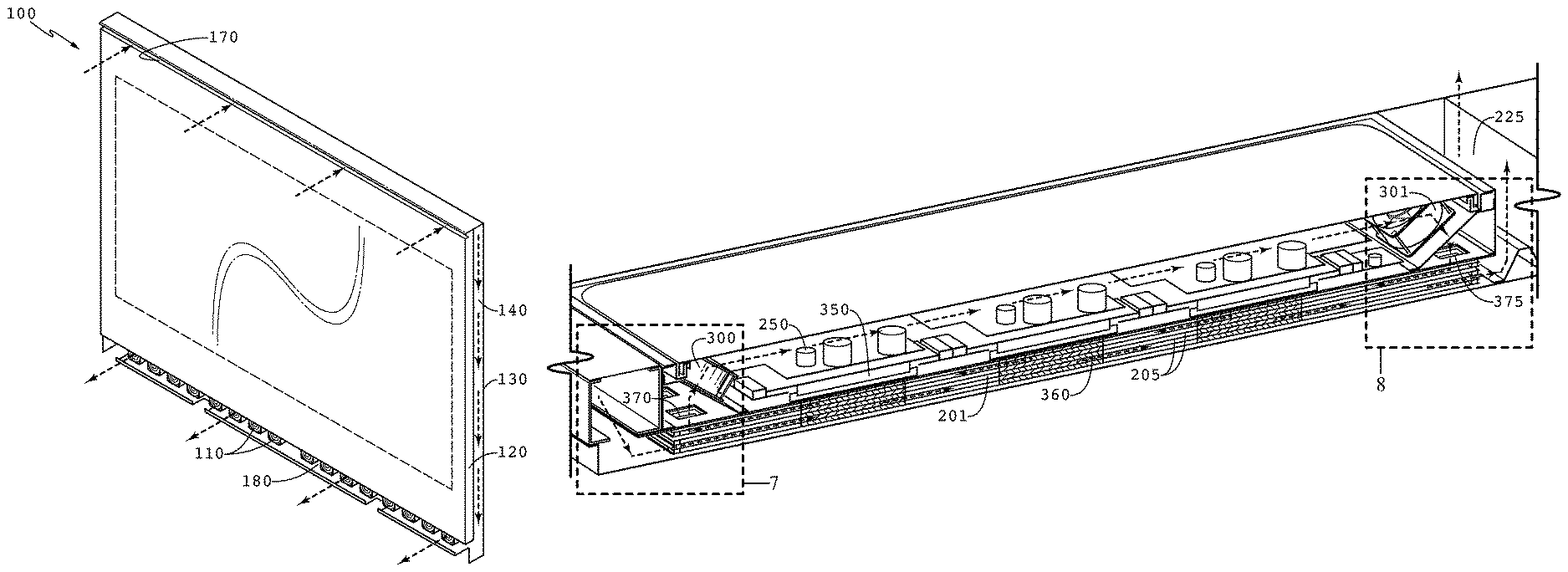
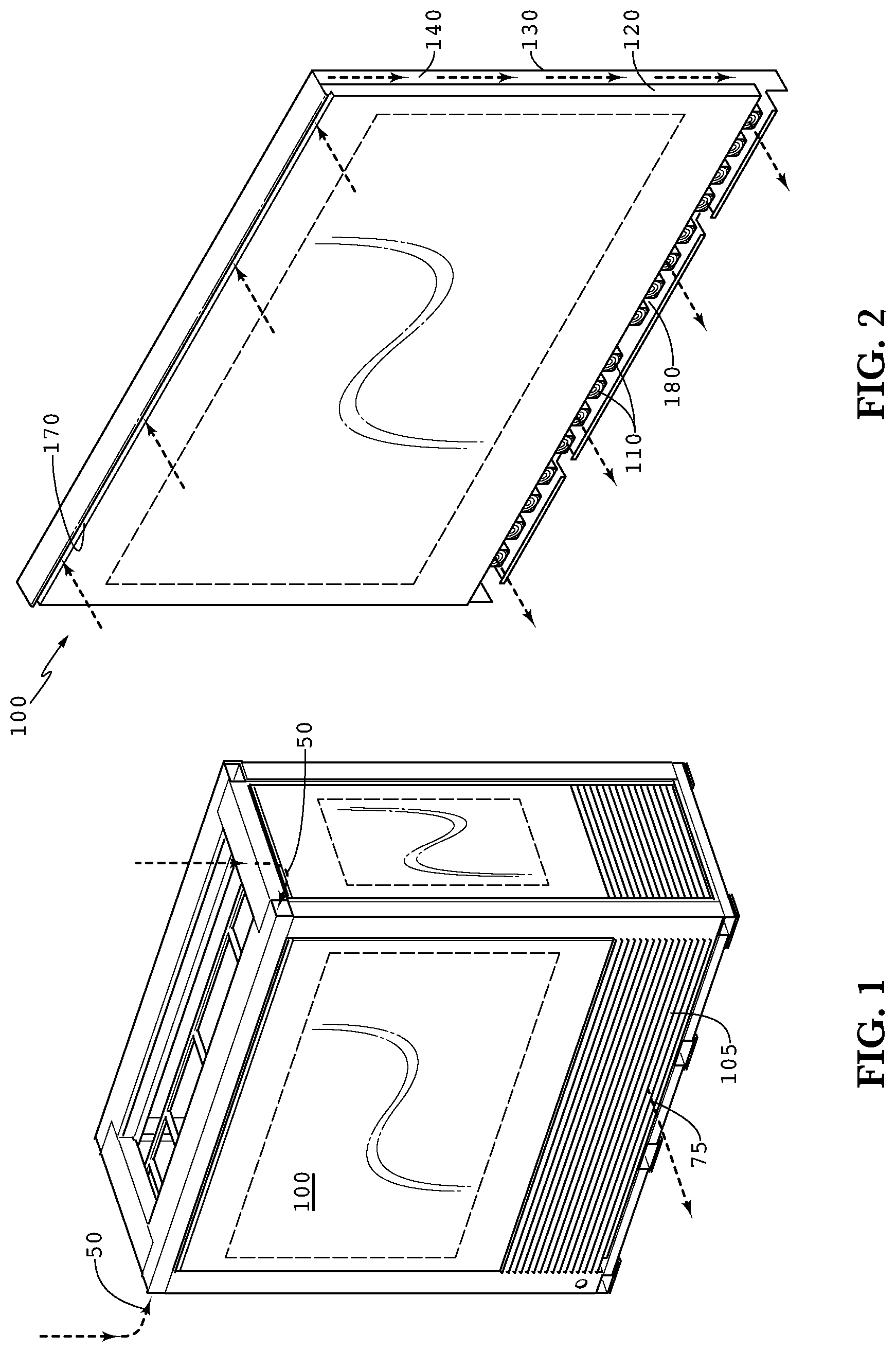
FIG. 1 is a perspective view of an exemplary electronic display assembly having a housing containing an electronic display subassembly 100 and an electronics and power subassembly 150. In an exemplary embodiment, the housing would have two separate flows of external air flowing through the housing. The first is shown in this figure where external air is ingested at the apertures 50 and is exhausted from the aperture 75.
FIG. 2 is a perspective view of the electronic display subassembly 100 after being removed from the assembly shown in FIG. 1. The electronic display 120 preferably has a pathway for external air running behind the display 120, this would provide the second flow of external air for an exemplary embodiment. In an exemplary embodiment, the inlet apertures 170 are positioned above the display and are in gaseous communication with a gap 140 behind the display, which ultimately connects with an exhaust aperture 180 positioned below the display. The gap 140 may be created by placing a surface or plate behind the rear surface of the electronic display 120. One or more fans 110 may be positioned to draw the external air through the inlet 170, gap 140, and exhaust 180.
The electronic display can be any variety of electronic display 120, including but not limited to liquid crystal display (LCD), LED, OLED, plasma, electroluminescent polymers, field emission display, and laser video displays. In an exemplary embodiment the electronic display 120 would comprise an LED backlit LCD where the rear surface of the electronic display 120 would be the rear surface of the LED backlight.
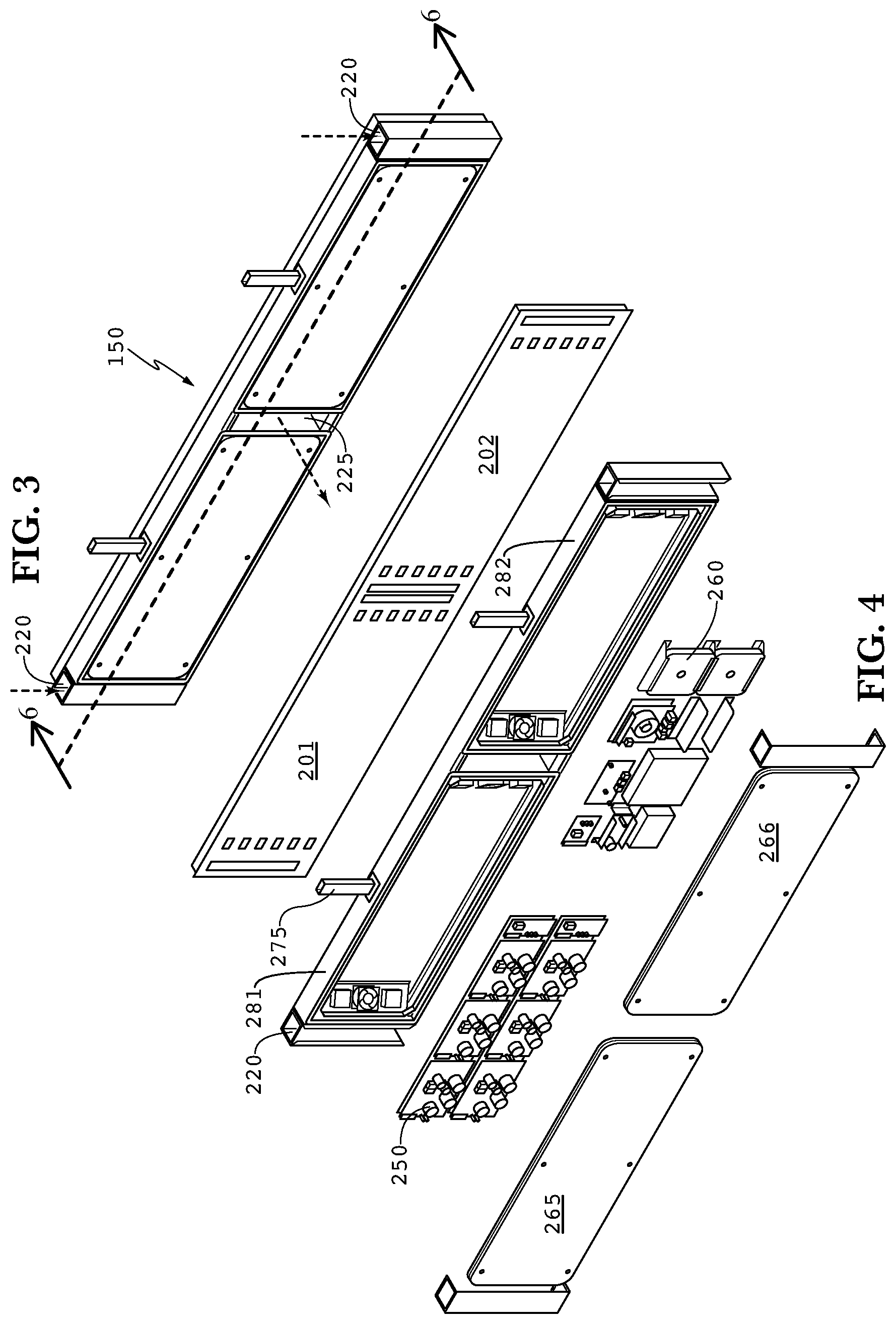
FIG. 3 is a perspective view of the electronics and power subassembly 150 after being removed from the assembly shown in FIG. 1 and illustrates the horizontal section line 6-6. A pair of inlet apertures 220 are preferably in gaseous communication with the inlet apertures 50 in the housing to supply external air to the assembly. This ingested external air is preferably exhausted through the exhaust aperture 225, which aligns with the exhaust aperture 75 in the housing.
FIG. 4 is an exploded view of the electronics and power subassembly 150 shown in FIG. 3. A first plenum enclosure is preferably created by the plenum walls 281, heat exchanger 201, and front cover 265. A second plenum enclosure is preferably created by the plenum walls 282, heat exchanger 202, and front cover 266. One or more power assemblies or power modules 250 may be placed within the first plenum enclosure. One or more electronic assemblies 260 may be placed within the second plenum enclosure. In an exemplary embodiment, the two plenum enclosures are substantially sealed, and do not accept external air, dust, or other contaminates other than the flow of external air described herein (which preferably would not enter the plenum enclosures, but would only flow through the heat exchangers 201 and 202 as described below).
Further, in an exemplary embodiment, the power modules 250 would be considered high voltage/high power electronics while the electronic assemblies 260 would be considered low voltage/low power electronics and these would be isolated into their own respective plenums. Generally speaking, the electronic assemblies 260 would include, but would not be limited to: hard drives, video players, microprocessors, wireless/satellite antennas, and CPU's. A wiring conduit 275 may provide wiring access into the plenums but should be substantially sealed so as not to allow contaminates or external air to enter the plenum through the wiring conduit 275. The wiring conduit 275 may provide the electrical communication between the low power and high power electronics and also between the low/high power electronics and the electronic display 120.
FIG. 5 is a perspective view of the electronics and power subassembly shown in FIG. 3 after removing the cover doors 265 and 266. A fan 310 may be placed in the inlet tube to draw the external air through the inlets, heat exchanger, and exhaust aperture 225. Alternatively, a fan 312 could be placed near the exhaust aperture 225. In some embodiments, both fans 310 and fan 312 may be used. In the first plenum, fans 300 and 301 are used to force a closed loop circulating gas through the plenum and heat exchanger 201. In the second plenum, fans 302 and 303 are used to force a closed loop circulating gas through the plenum and heat exchanger 202. Of course, in some embodiments only a single fan for each closed loop of circulating gas may be used rather than the pairing of fans shown herein.
FIG. 6 is a section view of the electronics and power subassembly 150 shown in FIG. 3, taken along the section line 6-6. Each power module 250 is preferably placed in conductive thermal communication with the heat exchanger 201. In an exemplary embodiment, the power brick 350 is preferably in conductive thermal communication with the heat exchanger 201, which is comprised of a plurality of layers 205, where the space in between each layer defines a gaseous pathway. In an exemplary embodiment, a metallic plate 360 is preferably placed between each layer 205 of the heat exchanger 201, and is positioned adjacent to the areas containing a power brick 350. The layers 205 of the heat exchanger 201 may be metallic or plastic (sometimes corrugated plastic or corrugated metal as shown in the Figures) or any combination of these materials. The heat exchangers 201 and 202 are preferably counterflow heat exchangers.
In an exemplary embodiment, the length and width of the metallic plates 360 are substantially the same as the length and width of the power bricks 350, however this is not required. Ideally, a series of metallic plates 360 may be aligned with each brick 350, such that a layer 205 of the heat exchanger is placed between the brick 350 and the first plate 360, as well as between each subsequent plate 360. While it may not be necessary to place a metallic plate 360 between every heat exchanger layer 205, this may be done in an exemplary embodiment. Each metallic plate 360 may be sandwiched between the layers 205 and may be held in place with adhesive.
The external air is forced through the heat exchanger 201 and exhausted out of the exhaust aperture 225. In this way, heat from the power module 250 may be transferred to the brick 350 and eventually to the plates 360 and heat exchanger layers 205 through conductive heat transfer. The external air removes heat from these assemblies as it passes through the heat exchanger 201.
Additionally, closed loop circulating gas is also travelling through the pathways of the heat exchanger 201, where the gas pathways may be defined as the space between heat exchanger layers 205. The layers 205 may be space apart based on the thickness of the plates 360, and held with this spacing once assembled around the plates 360. In this embodiment, the closed loop of circulating gas is forced around the closed loop by the pair of fans 300 and 301. The loop may be described as beginning at fan 301, traversing the pass through junction 375, travelling through the heat exchanger 201, traversing the pass through junction 370, passing the fan 300, and travelling across the power modules 250 before returning to the fan 301. The gas pathways alternate, where a pathway accepting circulating gas would be adjacent to a pathway accepting external air which is in turn adjacent to another pathway accepting circulating gas. Preferably, the circulating gas and external air are not permitted to mix with one another. However, as the two gases travel through their pathways, heat from the circulating gas can be transferred to the external air and removed from the display housing through the exhaust.
The opposing heat exchanger 202 is setup in a similar fashion as the heat exchanger 201 described above. The only difference would be that heat exchanger 202 would not contain the bricks 350, which are generally not used for the low power/voltage electronics 260. However, the metallic plates 360 may be used in the heat exchanger 202, in order to pull heat from the electronics 260 into the heat exchanger 202 for removal by the external air.
FIG. 7 is a detailed section view of DETAIL 7, shown in FIG. 6, where a second section has been taken vertically through the center of the pass through junctions. Here, the details of an exemplary pass through junction 370 are shown. Generally, the pass through junction 370 is placed near the end of the heat exchanger 201. Initially, note the blocking elements 212 which are positioned within each pathway 206 which contains the closed loop circulating gas. These blocking elements 212 run the entire length of the heat exchanger 201, to prohibit external air from entering the circulating gas pathways. Also note the cutout opening 371 in the heat exchanger which preferably passes through several, if not every layer 205 of the heat exchanger. While a blocking element 212 may be placed adjacent to the opening 371 on the end of the heat exchanger, the opposing side of the opening 371 is preferably free of any blocking so that the pathways 215 which accept circulating gas can provide gaseous communication through the opening 371 to continue the circulating closed loop path.
A series of donut gaskets 210 may be placed within each pathway 206 which accepts external air, such that the donut gasket 210 substantially surrounds and seals off the pathway 206 from the opening 371. In this way, external air traveling through the heat exchanger is permitted to flow through the pathway 206, but is not permitted to enter the opening 371 or mix with the circulating gas. The donut gaskets 210 do not preferably run the entire length of the heat exchanger, but would only surround the openings 371, which could be any shape but are typically found as rectangles, squares, circles, ovals, or some combination of these. The interior dimensions of the donut gaskets 210 preferable match that of the cutout 371. However, the exterior dimensions of the donut gaskets 210 can vary.
Although not required, it is preferable that the donut gaskets 210 are comprised of a compressible material, preferably an elastomer or rubber of some type, but soft and compressible materials have been found to provide acceptable results. In some embodiments, the donut gaskets 210 can simply comprise a sheet of compressible material having a void removed from the center, where that void can have any shape, including but not limited to any polygon, circle, or oval shape. Preferably, the donut gaskets 210 would have a continuous perimeter surrounding the void, which is preferably aligned with the opening 371, so that external air is not permitted to enter the opening 371, but can still travel through the pathway 206.
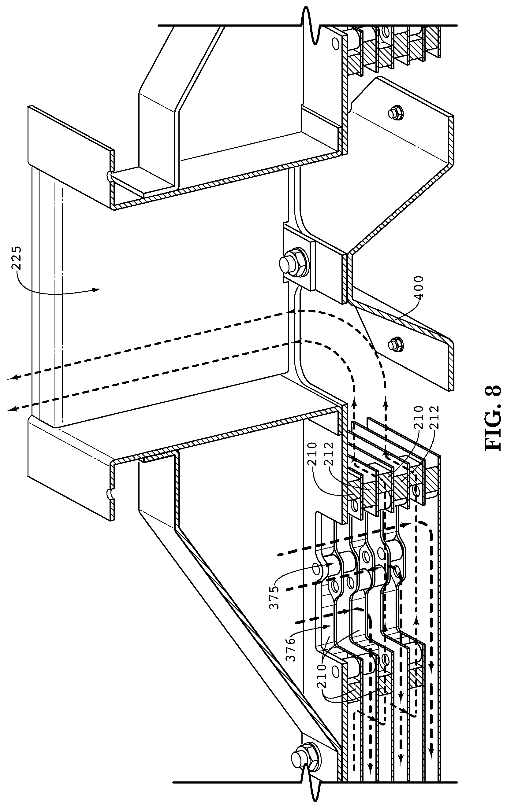
FIG. 8 is a detailed section view of DETAIL 8, shown in FIG. 6, where a second section has been taken vertically through the center of the pass through junctions. Here, the details of an exemplary opposing pass through junction 375 are shown. Again, the opposing pass through junction 375 is preferably placed near the end/edge of the heat exchanger 201. Also, again note the blocking elements 212 which are positioned within each pathway 206 which contains the closed loop circulating gas. These blocking elements 212 run the entire length of the heat exchanger 201, to prohibit external air from entering the circulating gas pathways. Also note the cutout opening 376 in the heat exchanger which preferably passes through several, if not every layer 205 of the heat exchanger. While a blocking element 212 may be placed adjacent to the opening 376 on the end of the heat exchanger, the opposing side of the opening 376 is preferably free of any blocking so that the pathways 206 which accept circulating gas can provide gaseous communication through the opening 376 to continue the circulating closed loop path.
A series of donut gaskets 210 may again be placed within each pathway 206 which accepts external air, such that the donut gasket 210 substantially surrounds and seals off the pathway 206 from the opening 376. In this way, external air traveling through the heat exchanger is permitted to flow through the pathway 206, but is not permitted to enter the opening 376 or mix with the circulating gas. Here, the external air would travel around the donut gasket 210, eventually exiting the heat exchanger and exhausting out of the exhaust aperture 225.
An angled redirection plate 400 is preferably placed after the heat exchanger and adjacent to the exhaust aperture 225 in order to change the direction of the external air approximately 90 degrees, or in other words to direct it towards the exhaust aperture 225.
Another pair of pass through junctions with their own gasket donuts and blocking elements are preferably used for the opposing side of the assembly, which houses the electronics 260. The design could be substantially the same, however in some embodiments it may be possible to use a smaller heat exchanger or perhaps one with fewer layers, as there may be less heat generated by the electronics 260 when compared to the power modules 250. There could also be fewer fans used on this side of the assembly as well.
It should be noted that the term circulating gas does not require a `pure` gas but could be any gaseous matter (which could of course be a mixture of various types of gases and even small amounts of contaminate, but the circulating gas would preferably have only a minimal amount of contaminates, and most preferably would be free of particulate and contaminates).
Having shown and described exemplary embodiments of the general inventive concept, those skilled in the art will realize that many variations and modifications may be made to affect the described embodiments and still fall within the scope of the general inventive concept. Thus, many of the elements indicated above may be altered or replaced by different elements which will provide the same result and fall within the spirit of the general inventive concept. It is the intention, therefore, to limit the general inventive concept only as indicated by the following claims.
* * * * *
D00000
D00001
D00002
D00003
D00004
D00005
D00006
XML
uspto.report is an independent third-party trademark research tool that is not affiliated, endorsed, or sponsored by the United States Patent and Trademark Office (USPTO) or any other governmental organization. The information provided by uspto.report is based on publicly available data at the time of writing and is intended for informational purposes only.
While we strive to provide accurate and up-to-date information, we do not guarantee the accuracy, completeness, reliability, or suitability of the information displayed on this site. The use of this site is at your own risk. Any reliance you place on such information is therefore strictly at your own risk.
All official trademark data, including owner information, should be verified by visiting the official USPTO website at www.uspto.gov. This site is not intended to replace professional legal advice and should not be used as a substitute for consulting with a legal professional who is knowledgeable about trademark law.