Methods and apparatus for active transparency modulation
Hazra , et al. Dec
U.S. patent number 10,522,106 [Application Number 15/587,260] was granted by the patent office on 2019-12-31 for methods and apparatus for active transparency modulation. This patent grant is currently assigned to Ostendo Technologies, Inc.. The grantee listed for this patent is Ostendo Technologies, Inc.. Invention is credited to Hussein S. El-Ghoroury, Siddharth S. Hazra.


| United States Patent | 10,522,106 |
| Hazra , et al. | December 31, 2019 |
Methods and apparatus for active transparency modulation
Abstract
A viewing system is provided including an active transparency modulation film in the form of addressable arrays of electrochromic pixel structures. The viewing system may be used in, for instance, a head-mounted display (HMD) or head-up display (HUD). The film is located on one side of a viewing lens of the system and is selectively variable from opaque to transparent at certain regions on the lens to provide an opaque silhouetted image upon which a virtual image is projected. The viewing system including the film and pixel structure therefore provide improved viewing by minimizing the undesirable effects of image ghosting in a viewed scene.
| Inventors: | Hazra; Siddharth S. (Carlsbad, CA), El-Ghoroury; Hussein S. (Carlsbad, CA) | ||||||||||
|---|---|---|---|---|---|---|---|---|---|---|---|
| Applicant: |
|
||||||||||
| Assignee: | Ostendo Technologies, Inc.
(Carlsbad, CA) |
||||||||||
| Family ID: | 60203402 | ||||||||||
| Appl. No.: | 15/587,260 | ||||||||||
| Filed: | May 4, 2017 |
Prior Publication Data
| Document Identifier | Publication Date | |
|---|---|---|
| US 20170323615 A1 | Nov 9, 2017 | |
Related U.S. Patent Documents
| Application Number | Filing Date | Patent Number | Issue Date | ||
|---|---|---|---|---|---|
| 62332168 | May 5, 2016 | ||||
| Current U.S. Class: | 1/1 |
| Current CPC Class: | G09G 3/38 (20130101); G02B 27/0172 (20130101); G09G 3/002 (20130101); G06T 1/20 (20130101); G06T 11/60 (20130101); G06F 3/147 (20130101); G02B 2027/0118 (20130101); G02B 2027/014 (20130101); G02B 2027/0178 (20130101); G09G 2360/08 (20130101); G09G 2320/064 (20130101); G09G 2360/144 (20130101); G09G 2340/12 (20130101); G09G 2320/0257 (20130101) |
| Current International Class: | G09G 3/38 (20060101); G02F 1/153 (20060101); G02B 27/01 (20060101); G06T 11/60 (20060101); G06T 1/20 (20060101); G09G 5/10 (20060101); G06F 3/147 (20060101); G09G 3/00 (20060101) |
References Cited [Referenced By]
U.S. Patent Documents
| 4427912 | January 1984 | Bui et al. |
| 4987410 | January 1991 | Berman et al. |
| 5162828 | November 1992 | Furness et al. |
| 5368042 | November 1994 | O'Neal et al. |
| 5619373 | April 1997 | Meyerhofer et al. |
| 5696521 | December 1997 | Robinson et al. |
| 5818359 | October 1998 | Beach |
| 5886822 | March 1999 | Spitzer |
| 5986811 | November 1999 | Wohlstadter |
| 6128003 | October 2000 | Smith et al. |
| 6147807 | November 2000 | Droessler et al. |
| 6151167 | November 2000 | Melville |
| 6353503 | March 2002 | Spitzer et al. |
| 6433907 | August 2002 | Lippert et al. |
| 6456438 | September 2002 | Lee et al. |
| 6522794 | February 2003 | Bischel et al. |
| 6529331 | March 2003 | Massof et al. |
| 6666825 | December 2003 | Smith et al. |
| 6710902 | March 2004 | Takeyama |
| 6719693 | April 2004 | Richard |
| 6795221 | September 2004 | Urey |
| 6803561 | October 2004 | Dunfield |
| 6804066 | October 2004 | Ha et al. |
| 6829095 | December 2004 | Amitai |
| 6924476 | August 2005 | Wine et al. |
| 6937221 | August 2005 | Lippert et al. |
| 6984208 | January 2006 | Zheng |
| 6999238 | February 2006 | Glebov et al. |
| 7061450 | June 2006 | Bright et al. |
| 7071594 | July 2006 | Yan et al. |
| 7106519 | September 2006 | Aizenberg et al. |
| 7190329 | March 2007 | Lewis et al. |
| 7193758 | March 2007 | Wiklof et al. |
| 7209271 | April 2007 | Lewis et al. |
| 7215475 | May 2007 | Woodgate et al. |
| 7232071 | June 2007 | Lewis et al. |
| 7369321 | May 2008 | Ren et al. |
| 7482730 | January 2009 | Davis et al. |
| 7486255 | February 2009 | Brown et al. |
| 7545571 | June 2009 | Garoutte |
| 7580007 | August 2009 | Brown et al. |
| 7619807 | November 2009 | Baek et al. |
| 7623560 | November 2009 | El-Ghoroury et al. |
| 7724210 | May 2010 | Sprague et al. |
| 7747301 | June 2010 | Cheng et al. |
| 7767479 | August 2010 | El-Ghoroury et al. |
| 7791810 | September 2010 | Powell |
| 7829902 | November 2010 | El-Ghoroury et al. |
| 7952809 | May 2011 | Takai |
| 8049231 | November 2011 | El-Ghoroury et al. |
| 8098265 | January 2012 | El-Ghoroury et al. |
| 8243770 | August 2012 | El-Ghoroury et al. |
| 8279716 | October 2012 | Gossweiler, III et al. |
| 8292833 | October 2012 | Son et al. |
| 8405618 | March 2013 | Colgate et al. |
| 8471967 | June 2013 | Miao et al. |
| 8477425 | July 2013 | Border et al. |
| 8482859 | July 2013 | Border |
| 8508830 | August 2013 | Wang |
| 8508851 | August 2013 | Miao et al. |
| 8510244 | August 2013 | Carson et al. |
| 8553910 | October 2013 | Dong et al. |
| 8567960 | October 2013 | El-Ghoroury et al. |
| 8619049 | December 2013 | Harrison et al. |
| 8725842 | May 2014 | Al-Nasser |
| 8743145 | June 2014 | Price |
| 8773599 | July 2014 | Saeedi et al. |
| 8854724 | October 2014 | El-Ghoroury et al. |
| 8928969 | January 2015 | Alpaslan et al. |
| 8975713 | March 2015 | Sako et al. |
| 9097890 | August 2015 | Miller et al. |
| 9110504 | August 2015 | Lewis et al. |
| 9134535 | September 2015 | Dobschal et al. |
| 9179126 | November 2015 | El-Ghoroury et al. |
| 9239453 | January 2016 | Cheng et al. |
| 9244277 | January 2016 | Cheng et al. |
| 9244539 | January 2016 | Venable et al. |
| 9274608 | March 2016 | Katz et al. |
| 9286730 | March 2016 | Bar-Zeev et al. |
| 9529191 | December 2016 | Sverdrup et al. |
| 9538182 | January 2017 | Mishourovsky et al. |
| 9681069 | June 2017 | El-Ghoroury et al. |
| 9712764 | July 2017 | El-Ghoroury et al. |
| 9774800 | September 2017 | El-Ghoroury et al. |
| 9779515 | October 2017 | El-Ghoroury et al. |
| 9965982 | May 2018 | Lapstun |
| 2002/0008854 | January 2002 | Leigh Travis |
| 2002/0017567 | February 2002 | Connolly et al. |
| 2002/0024495 | February 2002 | Lippert et al. |
| 2002/0075232 | June 2002 | Daum et al. |
| 2002/0083164 | June 2002 | Katayama et al. |
| 2002/0141026 | October 2002 | Wiklof et al. |
| 2002/0158814 | October 2002 | Bright et al. |
| 2002/0181115 | December 2002 | Massof et al. |
| 2002/0194005 | December 2002 | Lahr |
| 2003/0032884 | February 2003 | Smith et al. |
| 2003/0086135 | May 2003 | Takeyama |
| 2003/0122066 | July 2003 | Dunfield |
| 2003/0138130 | July 2003 | Cohen et al. |
| 2003/0184575 | October 2003 | Reho et al. |
| 2003/0187357 | October 2003 | Richard |
| 2004/0004585 | January 2004 | Brown et al. |
| 2004/0024312 | February 2004 | Zheng |
| 2004/0051392 | March 2004 | Badarneh |
| 2004/0080807 | April 2004 | Chen et al. |
| 2004/0080938 | April 2004 | Holman et al. |
| 2004/0085261 | May 2004 | Lewis et al. |
| 2004/0119004 | June 2004 | Wine et al. |
| 2004/0125076 | July 2004 | Green |
| 2004/0138935 | July 2004 | Johnson et al. |
| 2004/0179254 | September 2004 | Lewis et al. |
| 2004/0240064 | December 2004 | Dutta |
| 2005/0002074 | January 2005 | McPheters et al. |
| 2005/0024730 | February 2005 | Aizenberg et al. |
| 2005/0053192 | March 2005 | Sukovic et al. |
| 2005/0116038 | June 2005 | Lewis et al. |
| 2005/0117195 | June 2005 | Glebov et al. |
| 2005/0168700 | August 2005 | Berg et al. |
| 2005/0179976 | August 2005 | Davis et al. |
| 2005/0264502 | December 2005 | Sprague et al. |
| 2006/0017655 | January 2006 | Brown et al. |
| 2006/0132383 | June 2006 | Gally et al. |
| 2006/0152812 | July 2006 | Woodgate et al. |
| 2006/0253007 | November 2006 | Cheng et al. |
| 2006/0285192 | December 2006 | Yang |
| 2006/0290663 | December 2006 | Mitchell |
| 2007/0052694 | March 2007 | Holmes |
| 2007/0083120 | April 2007 | Cain et al. |
| 2007/0236450 | October 2007 | Colgate et al. |
| 2007/0269432 | November 2007 | Nakamura et al. |
| 2007/0276658 | November 2007 | Douglass |
| 2008/0002262 | January 2008 | Chirieleison |
| 2008/0049291 | February 2008 | Baek et al. |
| 2008/0130069 | June 2008 | Cernasov |
| 2008/0141316 | June 2008 | Igoe et al. |
| 2008/0239452 | October 2008 | Xu et al. |
| 2009/0073559 | March 2009 | Woodgate et al. |
| 2009/0086170 | April 2009 | El-Ghoroury et al. |
| 2009/0096746 | April 2009 | Kruse et al. |
| 2009/0161191 | June 2009 | Powell |
| 2009/0199900 | August 2009 | Bita et al. |
| 2009/0222113 | September 2009 | Fuller et al. |
| 2009/0256287 | October 2009 | Fu et al. |
| 2009/0268303 | October 2009 | Takai |
| 2009/0278998 | November 2009 | El-Ghoroury et al. |
| 2009/0327171 | December 2009 | Tan et al. |
| 2010/0003777 | January 2010 | El-Ghoroury et al. |
| 2010/0026960 | February 2010 | Sprague |
| 2010/0046070 | February 2010 | Mukawa |
| 2010/0053164 | March 2010 | Imai et al. |
| 2010/0066921 | March 2010 | El-Ghoroury et al. |
| 2010/0091050 | April 2010 | El-Ghoroury et al. |
| 2010/0156676 | June 2010 | Mooring et al. |
| 2010/0171922 | July 2010 | Sessner et al. |
| 2010/0199232 | August 2010 | Mistry et al. |
| 2010/0220042 | September 2010 | El-Ghoroury et al. |
| 2010/0241601 | September 2010 | Carson et al. |
| 2010/0245957 | September 2010 | Hudman et al. |
| 2010/0259472 | October 2010 | Radivojevic et al. |
| 2010/0267449 | October 2010 | Gagner et al. |
| 2011/0054360 | March 2011 | Son et al. |
| 2011/0115887 | May 2011 | Yoo et al. |
| 2011/0221659 | September 2011 | King, III et al. |
| 2011/0285666 | November 2011 | Poupyrev et al. |
| 2011/0285667 | November 2011 | Poupyrev et al. |
| 2012/0033113 | February 2012 | El-Ghoroury et al. |
| 2012/0075173 | March 2012 | Ashbrook et al. |
| 2012/0075196 | March 2012 | Ashbrook et al. |
| 2012/0105310 | May 2012 | Sverdrup et al. |
| 2012/0113097 | May 2012 | Nam et al. |
| 2012/0120498 | May 2012 | Harrison et al. |
| 2012/0143358 | June 2012 | Adams et al. |
| 2012/0154441 | June 2012 | Kim |
| 2012/0157203 | June 2012 | Latta et al. |
| 2012/0195461 | August 2012 | Lawrence Ashok Inigo |
| 2012/0212398 | August 2012 | Border et al. |
| 2012/0212399 | August 2012 | Border et al. |
| 2012/0218301 | August 2012 | Miller |
| 2012/0236201 | September 2012 | Larsen et al. |
| 2012/0249409 | October 2012 | Toney et al. |
| 2012/0249741 | October 2012 | Maciocci et al. |
| 2012/0288995 | November 2012 | El-Ghoroury et al. |
| 2012/0290943 | November 2012 | Toney et al. |
| 2012/0293402 | November 2012 | Harrison et al. |
| 2012/0299962 | November 2012 | White et al. |
| 2012/0319940 | December 2012 | Bress et al. |
| 2012/0320092 | December 2012 | Shin et al. |
| 2013/0016292 | January 2013 | Miao et al. |
| 2013/0021658 | January 2013 | Miao et al. |
| 2013/0027341 | January 2013 | Mastandrea |
| 2013/0041477 | February 2013 | Sikdar et al. |
| 2013/0050260 | February 2013 | Reitan |
| 2013/0080890 | March 2013 | Krishnamurthi |
| 2013/0083303 | April 2013 | Hoover et al. |
| 2013/0100362 | April 2013 | Saeedi et al. |
| 2013/0141895 | June 2013 | Alpaslan et al. |
| 2013/0162505 | June 2013 | Crocco et al. |
| 2013/0169536 | July 2013 | Wexler et al. |
| 2013/0176622 | July 2013 | Abrahamsson et al. |
| 2013/0187836 | July 2013 | Cheng et al. |
| 2013/0196757 | August 2013 | Latta et al. |
| 2013/0215516 | August 2013 | Dobschal et al. |
| 2013/0225999 | August 2013 | Banjanin et al. |
| 2013/0258451 | October 2013 | El-Ghoroury et al. |
| 2013/0271679 | October 2013 | Sakamoto |
| 2013/0285174 | October 2013 | Sako et al. |
| 2013/0286053 | October 2013 | Fleck et al. |
| 2013/0286178 | October 2013 | Lewis et al. |
| 2013/0321581 | December 2013 | El-Ghoroury et al. |
| 2014/0009845 | January 2014 | Cheng et al. |
| 2014/0024132 | January 2014 | Jia et al. |
| 2014/0049417 | February 2014 | Abdurrahman et al. |
| 2014/0049983 | February 2014 | Nichol et al. |
| 2014/0055352 | February 2014 | David et al. |
| 2014/0055692 | February 2014 | Kroll et al. |
| 2014/0085177 | March 2014 | Lyons et al. |
| 2014/0091984 | April 2014 | Ashbrook et al. |
| 2014/0098018 | April 2014 | Kim et al. |
| 2014/0098067 | April 2014 | Yang et al. |
| 2014/0118252 | May 2014 | Kim et al. |
| 2014/0129207 | May 2014 | Bailey et al. |
| 2014/0139454 | May 2014 | Mistry et al. |
| 2014/0139576 | May 2014 | Costa et al. |
| 2014/0147035 | May 2014 | Ding et al. |
| 2014/0168062 | June 2014 | Katz et al. |
| 2014/0176417 | June 2014 | Young et al. |
| 2014/0185142 | July 2014 | Gupta et al. |
| 2014/0200496 | July 2014 | Hyde et al. |
| 2014/0232651 | August 2014 | Kress et al. |
| 2014/0292620 | October 2014 | Lapstun |
| 2014/0300869 | October 2014 | Hirsch et al. |
| 2014/0301662 | October 2014 | Justice et al. |
| 2014/0304646 | October 2014 | Rossmann |
| 2014/0340304 | November 2014 | Dewan et al. |
| 2015/0001987 | January 2015 | Masaki et al. |
| 2015/0033539 | February 2015 | El-Ghoroury et al. |
| 2015/0035832 | February 2015 | Sugden et al. |
| 2015/0054729 | February 2015 | Minnen et al. |
| 2015/0058102 | February 2015 | Christensen et al. |
| 2015/0125109 | May 2015 | Robbins et al. |
| 2015/0138086 | May 2015 | Underkoffler et al. |
| 2015/0148886 | May 2015 | Rao et al. |
| 2015/0193984 | July 2015 | Bar-Zeev |
| 2015/0205126 | July 2015 | Schowengerdt |
| 2015/0220109 | August 2015 | von Badinski et al. |
| 2015/0235467 | August 2015 | Schowengerdt et al. |
| 2015/0277126 | October 2015 | Hirano et al. |
| 2015/0301256 | October 2015 | Takiguchi |
| 2015/0301383 | October 2015 | Kimura |
| 2015/0323990 | November 2015 | Maltz |
| 2015/0323998 | November 2015 | Kudekar et al. |
| 2015/0326842 | November 2015 | Huai |
| 2015/0381782 | December 2015 | Park |
| 2016/0018948 | January 2016 | Parvarandeh et al. |
| 2016/0026059 | January 2016 | Chung et al. |
| 2016/0028935 | January 2016 | El-Ghoroury et al. |
| 2016/0116738 | April 2016 | Osterhout |
| 2016/0182782 | June 2016 | El-Ghoroury et al. |
| 2016/0191765 | June 2016 | El-Ghoroury et al. |
| 2016/0191823 | June 2016 | El-Ghoroury et al. |
| 2016/0220232 | August 2016 | Takada et al. |
| 2016/0342151 | November 2016 | Dey, IV et al. |
| 2017/0065872 | March 2017 | Kelley |
| 2017/0069134 | March 2017 | Shapira et al. |
| 2017/0116897 | April 2017 | Ahn et al. |
| 2017/0184776 | June 2017 | El-Ghoroury et al. |
| 2017/0236295 | August 2017 | El-Ghoroury |
| 2017/0261388 | September 2017 | Ma et al. |
| 2017/0310956 | October 2017 | Perdices-Gonzalez |
| 103298410 | Sep 2013 | CN | |||
| 103546181 | Jan 2014 | CN | |||
| 103558918 | Feb 2014 | CN | |||
| 104460992 | Mar 2015 | CN | |||
| 0431488 | Jan 1996 | EP | |||
| 10-1552134 | Sep 2015 | KR | |||
| WO-2014/124173 | Aug 2014 | WO | |||
Other References
|
"International Search Report and Written Opinion of the International Searching Authority dated Aug. 23, 2017; International Application No. PCT/US2017/031441", dated Aug. 23, 2017. cited by applicant . "Invitation to Pay Additional Fees Dated Jun. 23, 2017; International Application No. PCT/US2017/031441", Jun. 23, 2017. cited by applicant . Ahumada, Jr., Albert J. et al., "Spatio-temporal discrimination model predicts temporal masking functions", Proceedings of SPIE--the International Society for Optical Engineering, Human vision and electronic imaging III, vol. 3299, 1998, 6 pp. total. cited by applicant . Beulen, Bart W. et al., "Toward Noninvasive Blood Pressure Assessment in Arteries by Using Ultrasound", Ultrasound in Medicine & Biology, vol. 37, No. 5, 2011, pp. 788-797. cited by applicant . Bickel, Bernd et al., "Capture and Modeling of Non-Linear Heterogeneous Soft Tissue", ACM Transactions on Graphics (TOG)--Proceedings of ACM SIGGRAPH 2009, vol. 28, Issue 3, Article No. 89, Aug. 2009, 9 pp. total. cited by applicant . Castellini, Claudio et al., "Using Ultrasound Images of the Forearm to Predict Finger Positions", IEEE Transactions on Neural Systems and Rehabilitation Engineering, vol. 20, No. 6, Nov. 2012, pp. 788-797. cited by applicant . Cobbold, Richard S., "Foundations of Biomedical Ultrasound", Oxford University Press, 2007, pp. 3-95. cited by applicant . Fattal, David et al., "A multi-directional backlight for a wide-angle, glasses-free three-dimensional display", Nature, vol. 495, Mar. 21, 2013, pp. 348-351. cited by applicant . Grossberg, Stephen et al., "Neural dynamics of saccadic and smooth pursuit eye movement coordination during visual tracking of unpredictably moving targets", Neural Networks, vol. 27, 2012, pp. 1-20. cited by applicant . Guo, Jing-Yi et al., "Dynamic monitoring of forearm muscles using one-dimensional sonomyography system", Journal of Rehabilitation Research & Development, vol. 45, No. 1, 2008, pp. 187-195. cited by applicant . Harrison, Chris et al., "Skinput: Appropriating the Body as an Input Surface", CHI '10 Proceedings of the SIGCHI Conference on Human Factors in Computing Systems, 2010, pp. 453-462. cited by applicant . Hsiao, Tzu-Yu et al., "Noninvasive Assessment of Laryngeal Phonation Function Using Color Doppler Ultrasound Imaging", Ultrasound in Med. & Biol., vol. 27, No. 8, 2001, pp. 1035-1040. cited by applicant . Hua, Hong et al., "A 3D integral imaging optical see-through head-mounted display", Optics Express, vol. 22, No. 11, May 28, 2014, pp. 13484-13491. cited by applicant . Keir, Peter J. et al., "Changes in geometry of the finger flexor tendons in the carpal tunnel with wrist posture and tendon load: an MRI study on normal wrists", Clinical Biomechanics, vol. 14, 1999, pp. 635-645. cited by applicant . Khuri-Yakub, Butrus T. et al., "Capacitive micromachined ultrasonic transducers for medical imaging and therapy", J. Micromech. Microeng., vol. 21, No. 5, May 2011, pp. 054004-054014. cited by applicant . Koutsouridis, G. G. et al., "Towards a Non-Invasive Ultrasound Pressure Assessment in Large Arteries", Technische Universiteit Eindhoven, University of Technology, Mate Poster Award 2010: 15th Annual Poster Contest, 2010, 1 page total. cited by applicant . Lanman, Douglas et al., "Near-Eye Light Field Displays", ACM Transactions on Graphics (TOC), vol. 32, Issue 6, Article 220, Nov. 2013, 27 pp. total. cited by applicant . Legros, M. et al., "Piezocomposite and CMUT Arrays Assessment Through In Vitro Imaging Performances", 2008 IEEE Ultrasonics Symposium, Nov. 2-5, 2008, pp. 1142-1145. cited by applicant . Martin, Joel R. et al., "Changes in the flexor digitorum profundus tendon geometry in the carpal tunnel due to force production and posture of metacarpophalangeal joint of the index finger: An MRI study", Clinical Biomechanics, vol. 28, 2013, pp. 157-163. cited by applicant . Martin, Joel R. et al., "Effects of the index finger position and force production on the flexor digitorum superficialis moment arms at the metacarpophalangeal joints--a magnetic resonance imaging study", Clinical Biomechanics, vol. 27, 2012, pp. 453-459. cited by applicant . Marwah, Kshitij et al., "Compressive Light Field Photography using Overcomplete Dictionaries and Optimized Projections", Proc. of SIGGRAPH 2013 (ACM Transactions on Graphics, 32, 4), 2013, 12 pp. total. cited by applicant . Mujibiya, Adiyan et al., "The Sound of Touch: On-body Touch and Gesture Sensing Based on Transdermal Ultrasound Propagation", ITS '13 Proceedings of the 2013 ACM international conference on Interactive tabletops and surfaces, Oct. 6-9, 2013, pp. 189-198. cited by applicant . Paclet, Florent et al., "Motor control theories improve biomechanical model of the hand for finger pressing tasks", Journal of Biomechanics, vol. 45, 2012, pp. 1246-1251. cited by applicant . Pinton, Gianmarco F. et al., "A Heterogeneous Nonlinear Attenuating Full-Wave Model of Ultrasound", IEEE Transactions on Ultrasonics, Ferroelectrics, and Frequency Control, vol. 56, No. 3, Mar. 2009, pp. 474-488. cited by applicant . Richard, William D. et al., "A scalable architecture for real-time synthetic-focus imaging", Ultrasonic Imaging, vol. 25, 2003, pp. 151-161. cited by applicant . Rolland, Jannick P. et al., "Dynamic focusing in head-mounted displays", Part of the IS&T/SPIE Conference on the Engineering Reality of Virtual Reality, SPIE vol. 3639, Jan. 1999, pp. 463-470. cited by applicant . Shi, Jun et al., "Feasibility of controlling prosthetic hand using sonomyography signal in real time: Preliminary study", Journal of Rehabilitation Research & Development, vol. 47, No. 2, 2010, pp. 87-97. cited by applicant . Sikdar, Siddhartha et al., "Novel Method for Predicting Dexterous Individual Finger Movements by Imaging Muscle Activity Using a Wearable Ultrasonic System", IEEE Transactions on Neural Systems and Rehabilitation Engineering, vol. 22, No. 1, Jan. 2014, pp. 69-76. cited by applicant . Sueda, Shinjiro et al., "Musculotendon Simulation for Hand Animation", ACM Transactions on Graphics (TOG)--Proceedings of ACM SIGGRAPH 2008, vol. 27 Issue 3, Article No. 83, vol. 27 Issue 3, Aug. 2008, 8 pp. total. cited by applicant . Szabo, Thomas L., "Diagnostic Ultrasound Imaging: Inside Out, Second Edition", Elsevier Inc., 2013, 829 pp. total. cited by applicant . Van Den Branden Lambrecht, Christian J., "A Working Spatio-Temporal Model of the Human Visual System for Image Restoration and Quality Assessment Applications", ICASSP-96, Conference Proceedings of the 1996 IEEE International Conference on Acoustics, Speech, and Signal Processing, May 1996, 4 pp. total. cited by applicant . Watson, Andrew B. et al., "Model of human visual-motion sensing", Journal of the Optical Society of America A, vol. 2, No. 2, Feb. 1985, pp. 322-342. cited by applicant . Watson, Andrew B. et al., "Model of visual contrast gain control and pattern masking", Journal of the Optical Society of America A, vol. 14, No. 9, Sep. 1997, pp. 2379-2391. cited by applicant . Watson, Andrew B., "The search for optimal visual stimuli", Vision Research, vol. 38, 1998, pp. 1619-1621. cited by applicant . Watson, Andrew B., "The Spatial Standard Observer: A Human Visual Model for Display Inspection", Society for Information Display, SID 06 Digest, Jun. 2006, pp. 1312-1315. cited by applicant . Watson, Andrew B., "Visual detection of spatial contrast patterns: Evaluation of five simple models", Optics Express, vol. 6, No. 1, Jan. 3, 2000, pp. 12-33. cited by applicant . Wikipedia, "List of refractive indices", https://en.wikipedia.org/wiki/List_of_refractive_indices, Dec. 7, 2003, 5 pp. total. cited by applicant . Williams III, T. W., "Progress on stabilizing and controlling powered upper-limb prostheses", Journal of Rehabilitation Research & Development, Guest Editorial, vol. 48, No. 6, 2011, pp. ix-xix. cited by applicant . Willis, Karl D. et al., "MotionBeam: A Metaphor for Character Interaction with Handheld Projectors", CHI '11 Proceedings of the SIGCHI Conference on Human Factors in Computing Systems, May 7-12, 2011, pp. 1031-1040. cited by applicant . Yun, Xiaoping et al., "Design, Implementation, and Experimental Results of a Quaternion-Based Kalman Filter for Human Body Motion Tracking", IEEE Transactions on Robotics, vol. 22, No. 6, Dec. 2006, pp. 1216-1227. cited by applicant . Zhang, Cha et al., "Maximum Likelihood Sound Source Localization and Beamforming for Directional Microphone Arrays in Distributed Meetings", IEEE Transactions on Multimedia, vol. 10, No. 3, Apr. 2008, pp. 538-548. cited by applicant. |
Primary Examiner: Sajous; Wesner
Attorney, Agent or Firm: Womble Bond Dickinson (US) LLP
Parent Case Text
CROSS-REFERENCE TO RELATED APPLICATIONS
This application claims the benefit of U.S. Provisional Patent Application No. 62/332,168, filed May 5, 2016, the entirety of which is incorporated herein by reference.
Claims
What is claimed is:
1. A method of minimizing the undesirable effects of image ghosting in a viewed scene of a viewing system, the method comprising: providing a see-through optical lens or waveguide element with an active transparency modulation film comprising an electrochromatic pixel layer applied to one side of the see-through optical lens or waveguide element, each pixel being electrically controllable by a processor to be transparent in a first state and to be opaque in a second state, and variable between the first state and the second state by proportional voltage or pulse width modulation; defining, by control of selected pixels of the electrochromatic pixel layer, an area of lesser transparency to a viewer on the see-through optical lens or waveguide element; and projecting an image onto the area of lesser transparency from the viewing side of the see-through optical lens or waveguide element; whereby the image is superimposed onto the area of lesser transparency.
2. The method of claim 1 further comprising controlling which pixels are selected to determine the position of the area of lesser transparency of the see-through optical lens or waveguide element and controlling the position of the projected image on the see-through optical lens or waveguide element to keep the projected image superimposed on the area of lesser transparency as the projected image moves relative to the see-through optical lens or waveguide element.
3. The method of claim 1 wherein the image is generated under program control.
4. The method of claim 1 wherein a degree of transparency of the area of lesser transparency is based on an ambient illumination of the viewer's environment.
5. The method of claim 1 wherein defining the area of lesser transparency comprises determining a boundary of the image using an image segmentation process.
6. The method of claim 5 wherein the image segmentation process is a convex hull algorithm.
7. The method of claim 1 further comprising scanning for a light source and determining a location of the light source, wherein defining the area of lesser transparency is based on the location of the light source.
8. The method of claim 1 further comprising obtaining information regarding the viewer's eye gaze direction, interpupillary distance and head orientation to calculate a depth of the viewer's focus.
9. A non-transitory machine-readable medium having instructions stored thereon, which when executed by a processor cause the processor to perform the following method of minimizing the undesirable effects of image ghosting in a viewed scene of a viewing system, the method comprising: providing a see-through optical lens or waveguide element with an active transparency modulation film comprising an electrochromatic pixel layer applied to one side of the see-through optical lens or waveguide element, each pixel being electrically controllable by a processor to be transparent in a first state and to be opaque in a second state, and variable between the first state and the second state by proportional voltage or pulse width modulation; defining, by control of selected pixels of the electrochromatic pixel layer, an area of lesser transparency to a viewer on the see-through optical lens or waveguide element; and projecting an image onto the area of lesser transparency from the viewing side of the see-through optical lens or waveguide element; whereby the image is superimposed onto the area of lesser transparency.
Description
FIELD
One aspect of the present disclosure generally relates to active transparency modulation of lens elements for near-eye displays, wearable displays, augmented reality displays and virtual reality displays.
BACKGROUND
Numerous deficiencies exist in passive optics and waveguides currently used in near-eye, wearable and projected displays in augmented, mixed and virtual reality applications. Conventional passive optics tend to create see-through or "ghosted" images or objects instead of an impression of solidity and lead to a ghosted effect of the displayed object as perceived by a viewer. Stereoscopy with ghosted objects also creates complicated issues for binocular vision applications.
Conventional transparent lens/display substrates also typically suffer from display quality degradation in the presence of ambient illumination or specular reflection sources in the environment around the user from sources such as sunlight, lamps, headlights or reflections from reflective surfaces.
Current attempts to overcome the above-described ghosting problem have included, for instance, increasing display brightness and/or contrast and reducing the light that is admitted through the viewing lens using a visor element that partially gates the amount of light admitted to the user's eyes. Unfortunately, such prior approaches tend to reduce the "immersiveness" of the display quality and may also increase power consumption. Additionally, such prior approaches are typically application-dependent and necessarily require the use of three distinct, application-specific technologies to meet the different requirements for each of the mixed, augmented or virtual reality systems respectively.
BRIEF DESCRIPTION OF THE DRAWINGS
The embodiments herein are illustrated by way of example and not by way of limitation in the figures of the accompanying drawings in which like references indicate similar elements. It should be noted that references to "an" or "one" embodiment in this disclosure are not necessarily to the same embodiment, and they mean at least one.
In the drawings:
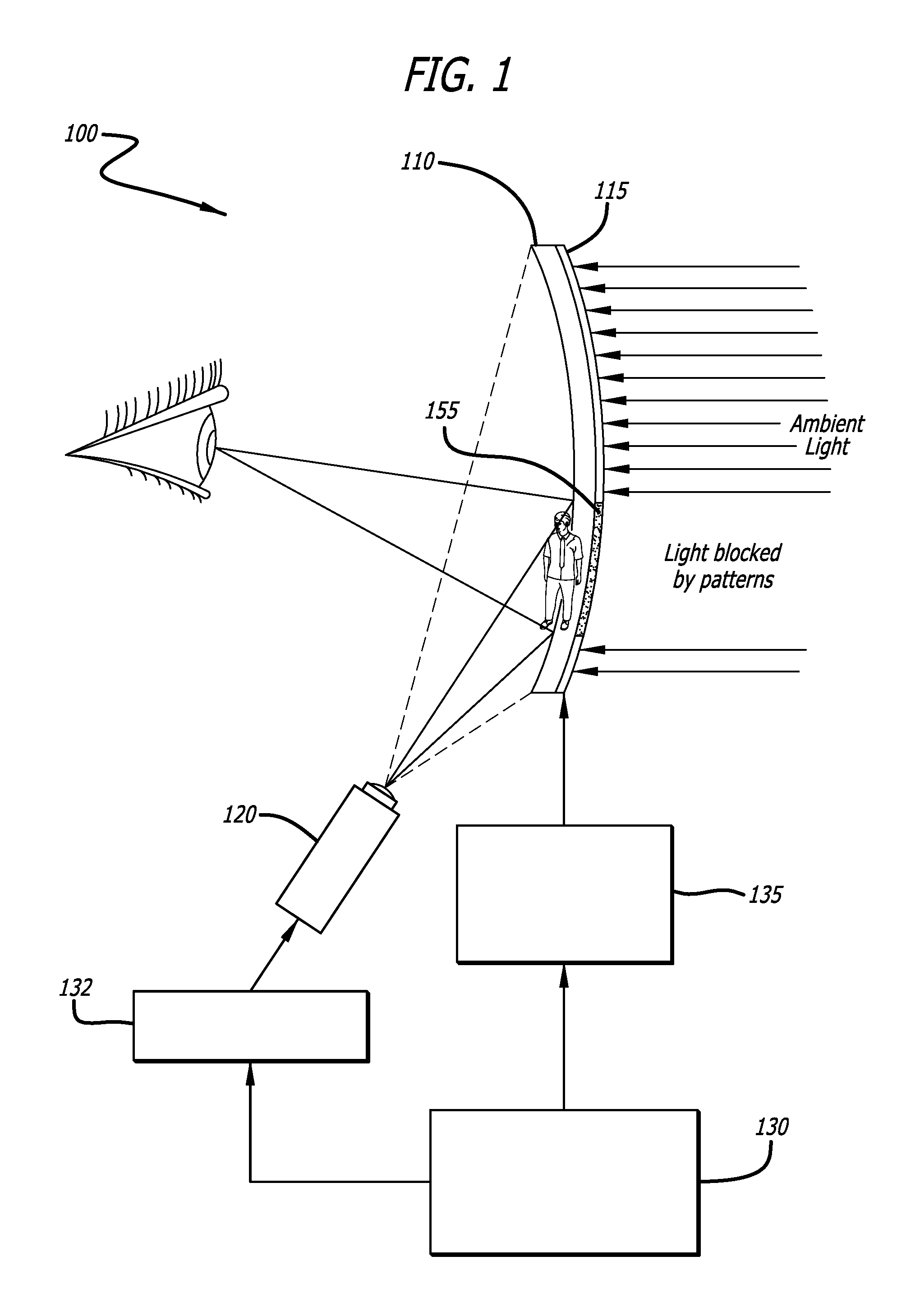
FIG. 1 illustrates a first example for explaining a viewing system for active transparency modulation according to an embodiment.
FIG. 2 illustrates a second example for explaining a viewing system for active transparency modulation according to an embodiment.
FIG. 3 illustrates an example for explaining a wearable near-eye display according to an embodiment.
FIG. 4 illustrates a view for explaining a "ghosted" translucent image of a predetermined augmented reality image (e.g., a person) as viewed through a pair of conventional augmented reality near-eye glasses.
FIG. 5 illustrates a view for explaining an opaque silhouetted augmented reality image (e.g., a person) selectively formed on an active transparency modulation film as viewed through a pair of augmented reality near-eye glasses incorporating an active transparency modulation film according to an embodiment.
FIG. 6 illustrates a view for explaining an ""unghosted"" augmented reality image (e.g., a person) projected upon and superimposed over an opaque silhouetted image such as the opaque silhouetted augmented reality image of FIG. 5 according to an embodiment.
FIG. 7 illustrates a view for explaining a virtual reality image (e.g., a person) projected upon an opaque viewing area of an active transparency modulation film as viewed in a pair of virtual-reality near-eye glasses according to an embodiment.
FIG. 8 illustrates a view for explaining an automobile heads-up display (HUD) incorporating an active transparency modulation film in which a displayed image is projected upon and superimposed over a predetermined opaque region of the HUD according to an embodiment.
FIGS. 9A-9E illustrate examples for explaining selective object masking and projected object textures superimposed on physical objects according to an embodiment.
FIGS. 10A-10D illustrate examples for explaining convex hulls according to an embodiment.
FIG. 11 illustrates a flow diagram for explaining an example method for active transparency modulation according to an embodiment herein.
DETAILED DESCRIPTION
The present disclosure and various of its embodiments are set forth in the following description of the embodiments which are presented as illustrated examples of the disclosure in the subsequent claims. It is expressly noted that the disclosure as defined by such claims may be broader than the illustrated embodiments described below. The word "exemplary" is used herein to mean serving as an example, instance, or illustration. Any aspect or design described herein as "exemplary" is not necessarily to be construed as preferred or advantageous over other aspects or designs.
According to one aspect of the disclosure herein, a viewing system is provided including an active transparency modulation film comprised of addressable arrays of electrochromic pixel structures and electronics that may be used in a head mounted display (HMD) and a head-up display (HUD). In one embodiment, the active transparency modulation film may be electrically controllable from highly transparent to highly reflective. The active transparency modulation film, pixel structures and supporting processing electronics (e.g., circuitry) provide improved viewing, such as by minimizing the undesirable effects of image ghosting in a viewed scene.
By virtue of the embodiments disclosed herein, it is possible to provide a low-power system solution that can be configured to transition between mixed, augmented, and virtual reality modalities, such that the deficiencies commonly found in conventional augmented reality, mixed reality, and virtual reality wearable devices are addressed. For example, display quality may be improved and ghosting may be reduced by virtue of the embodiments disclosed herein.
Turning to the embodiment depicted in FIG. 1, a viewing system 100 may comprise an imaging unit 120 comprising a light engine and an imager to project displayed content (e.g., still or moving images). The viewing system 100 may also comprise a see-through patterned optical lens 110 or one or more waveguide elements operating in cooperation with one or more user-defined refractive or diffractive optical elements and beam-splitting elements that are disposed within thickness of optical lens 110, whereby displayed content from imaging unit 120 is transmitted through the thickness of optical lens 110 and projected toward the pupil of the viewer. Examples of such devices incorporating the above refractive or diffractive optical and beam-splitting elements are disclosed in, for instance, copending U.S. patent application Ser. No. 15/381,459, filed Dec. 16, 2016, entitled "Systems and Methods for Augmented Near-Eye Wearable Displays", and, U.S. patent application Ser. No. 15/294,447, filed Oct. 14, 2016, entitled "Dual-Mode Augmented/Virtual Reality (AR/VR) Near-Eye Wearable Displays", the entirety of each of which is incorporated herein by reference. Lens 110 may be comprised of glass or polymer.
Lens 110 includes an active transparency modulation film 115 comprising an electrochromic pixel layer that is constructed to allow alteration of light transmission properties of film 115 by applying an electrical current or potential. In the embodiment of FIG. 1, film 115 is an electrochromic pixel layer applied to the scene-facing side of lens 110. In other embodiments, film 115 may be applied to either side of the lens 110. In one embodiment, film 115 itself may be a composite of transparent polymer substrates, transparent conductive oxide electrodes, thin film transistor arrays, and electrochromic pixel arrays. In other embodiments, film 115 may be a composite of any combination of: transparent polymer substrates, transparent conductive oxide electrodes, thin film transistor arrays, and electrochromic pixel arrays. In embodiments involving transparent conductive oxide electrodes, film 115 may be in electrical connection through the transparent conductive oxide electrodes to the other components of viewing system 100.
In one embodiment, pixels of the electrochromic pixel layer may be pulse-width modulated ("PWM") in order to actively control transparency modulation of the film 115. In addition, proportional voltage or current modulation can be used for ratiometric control of the admitted ambient light through the electrochromic film layer 115. The translucency of the lens element 110 can thereby be modulated between optically clear and opaque states. Accordingly, viewing system 100 may be switched between augmented or mixed reality modes to a virtual reality mode.
In one embodiment, the pixels of the electrochromic film 115 may have a different spatial resolution than the light engine of the imaging unit 120 used for projected display. For example, the spatial resolution of the pixels of the electrochromic film 115 may be lower than that of the light engine of the imaging unit 120.
In one embodiment, the electrochromic pixel layer (also referred to herein as the electrochromic film) may be comprised of materials such as a tungsten trioxide ("WO.sub.3") thin film or a polymer dispersed liquid crystal ("PDLC")-based film laminated on the surface of the optical lens 110. These films are bi-stable and active power is not required to maintain the On or Off state of the film. In other words, for electrochromic film that is electrochromatically bi-stable, once a color change has occurred, the state of film 115 remains even in absence of excitation or pulse modulation.
It is generally known that WO.sub.3 does not typically switch well at high frequencies and that WO.sub.3 is generally not well-suited for active displays due to its relatively slow switching rate of .about.100 msec. On the other hand, PDLC based films can typically be switched at acceptably high rates. While WO.sub.3 exhibits relatively slow switching rates, the content rate (i.e., the rate at which content moves across a user's field of view in a near-eye display) is far slower than the display refresh (frame) rate. This distinction between content and display refresh rates allows the use of electrochromic materials that may have slower switching frequencies in the embodiments herein. In some embodiments, the display refresh rate may be controlled by imagers such as the Quantum Photonic Imager or "QPI.RTM." imager (discussed below), DLP, LCoS, OLED or LBS light modulation engines.
Thus, the electrochromic content refresh rate is typically slower than the display refresh rate. In one embodiment, a display refresh rate may be approximately .about.60 Hz or greater and a content refresh may be approximately .about.10 Hz or greater, thus making it possible to switch WO.sub.3 mode well within the content refresh rate.
In one embodiment, the imager of the imaging unit 120 is capable of filling the field of view of the range of the possible positions of a projected image, and only uses a portion of the projection capability (e.g., a subset of pixels) for smaller images within that field of view. In one embodiment, the imager moves or actuates to cover the range of the possible positions of a projected image with respect to the see-through optical lens or waveguide element.
With respect to imagers, a new class of emissive micro-scale pixel array imager devices has been introduced as disclosed in U.S. Pat. No. 7,623,560, U.S. Pat. No. 7,767,479, U.S. Pat. No. 7,829,902, U.S. Pat. No. 8,049,231, U.S. Pat. No. 8,243,770, and U.S. Pat. No. 8,567,960, the contents of each of which is fully incorporated herein by reference. The disclosed light emitting structures and devices referred to herein may be based on the Quantum Photonic Imager or "QPI.RTM." imager. QPI.RTM. is a registered trademark of Ostendo Technologies, Inc. These disclosed devices desirably feature high brightness, very fast multi-color light intensity and spatial modulation capabilities, all in a very small single device size that includes all necessary image processing drive circuitry. The solid-state light-(SSL) emitting pixels of the disclosed devices may be either a light emitting diode (LED) or laser diode (LD), or both, whose on-off state is controlled by drive circuitry contained within a CMOS chip (or device) upon which the emissive micro-scale pixel array of the imager is bonded and electronically coupled. The size of the pixels comprising the disclosed emissive arrays of such imager devices is typically in the range of approximately 5-20 microns with a typical emissive surface area being in the range of approximately 15-150 square millimeters. The pixels within the above emissive micro-scale pixel array devices are individually addressable spatially, chromatically and temporally, typically through the drive circuitry of its CMOS chip. The brightness of the light generated by such imager devices can reach multiple 100,000 cd/m2 at reasonably low power consumption.
The QPI imager is well-suited for use in the imagers described herein. See U.S. Pat. No. 7,623,560, U.S. Pat. No. 7,767,479, U.S. Pat. No. 7,829,902, U.S. Pat. No. 8,049,231, U.S. Pat. No. 8,243,770, and U.S. Pat. No. 8,567,960. However, it is to be understood that the QPI imagers are merely examples of the types of devices that may be used in the present disclosure, which devices may, by way of a non-limiting set of examples, include OLED, LED, micro-LED imaging devices. Thus, in the disclosure herein, references to the QPI imager, display, display device or imager are to be understood to be for purposes of specificity in the embodiments disclosed, and not for any limitation of the present disclosure.
Returning to the embodiment of FIG. 1, video coprocessor 132 extracts at least one rendered content outline (e.g., boundary of the content to be displayed) from a video random access memory (VRAM) of graphics processing unit (GPU) 130 which contains "k buffer" information. Generally, a k buffer algorithm is a GPU-based fragment-level sorting algorithm for rendering transparent surfaces. The extracted outline is provided to film layer control coprocesser 135 which then activates the pixels of the electrochromic film 115 to block light at only the pixels 155 that are contained inside the extracted outline. Imaging unit 120 projects the image content onto film 115 in accordance with the pixels inside the extracted outline.
In this context, blocking refers to reflecting or absorbing light incident on pixels of the electrochromic film 115 that are controlled by the electrochromic layer control coprocessor 135 to reflect or absorb only light incident at the pixels 155 that are contained inside the extracted outline, resulting at least some of the incident light being blocked by the patterns), such that a portion of the film 115 is opaque to some degree (e.g., the portion containing pixels 155). In one embodiment, the blocking may be controlled to range from substantially no blocking to substantially full blocking. Such control may be achieved by proportional excitation of at least a portion of electrochromic film 115, or by pulse modulation of at least a portion of electrochromic film 115, or by pulse modulation of at least the portion of the electrochromic film that is at least partially electrochromically bistable, as discussed above.
In one embodiment, the intensity of the modulation of the electrochromic pixel layer 115 (e.g., degree or level of transparency) may further be controlled based upon the ambient illumination of the environment of the user.
In one embodiment, one or more of the processors of viewing system 100 (e.g., GPU 130, video coprocessor 132, electrochromic layer control coprocessor 135) may also be connected to a memory block that can be implemented via one or more memory devices including volatile storage (or memory) devices such as random access memory (RAM), dynamic RAM (DRAM), synchronous DRAM (SDRAM), static RAM (SRAM), or other types of storage devices. The one or more of the processors may be implemented in software, hardware, or a combination thereof. For example, the one or more of the processors can be implemented as software installed and stored in a persistent storage device, which can be loaded and executed in a memory by the processor to carry out the processes or operations described throughout this application. The one or more of the processors may each represent a single processor or multiple processors with a single processor core or multiple processor cores included therein. The one or more of the processors may each represent a microprocessor, a central processing unit (CPU), graphic processing unit (GPU), or the like. The one or more of the processors may each be a complex instruction set computing (CISC) microprocessor, reduced instruction set computing (RISC) microprocessor, matched instruction set microprocessor (MISP), very long instruction word (VLIW) microprocessor, or processor implementing other instruction sets, or processors implementing a combination of instruction sets. The one or more of the processors can also be implemented as executable code programmed or embedded into dedicated hardware such as an integrated circuit (e.g., an application specific IC or ASIC), a digital signal processor (DSP), or a field programmable gate array (FPGA), which can be accessed via a corresponding driver and/or operating system from an application. The one or more of the processors may each be a cellular or baseband processor, a network processor, a graphics processor, a communications processor, a cryptographic processor, an embedded processor, or any other type of logic capable of processing instructions. Furthermore, the one or more of the processors can be implemented as specific hardware logic in a processor or processor core as part of an instruction set accessible by a software component via one or more specific instructions.
Turning to the embodiment of FIG. 2, similar to the embodiment of FIG. 1, viewing system 200 includes lens 210 (e.g., glass or polymer see-through patterned optics similar to lens 110), film 215 (e.g., similar to film 115), electrochromic layer control coprocessor 235 (e.g., similar to electrochromic layer control coprocessor 135), GPU 230 (e.g., similar to GPU 130), video coprocessor 232 (e.g., similar to video coprocessor 132), and an imaging unit 220 (e.g., similar to imaging unit 120). Also similar to FIG. 1, video coprocessor 232 determines an outline of content to be displayed and the outline is provided to electrochromic layer control coprocessor 235 which then activates the pixels of the electrochromic film 215 to block light incident at pixels 255 that are inside the image outline, resulting in at least some of the incident light being reflected or absorbed by the pattern. Similar to FIG. 1, pixels of the film layer 215 may be actively controlled by proportional excitation of at least a portion of electrochromic film 215, or by pulse modulation of at least a portion of electrochromic film 215, or by pulse modulation of at least the portion of the electrochromic film that is at least partially electrochromically bistable.
In the embodiment of FIG. 2, viewing system 200 includes one or more environment (or ambient scene) monitoring cameras 240 that may obtain data used to generate image outlines by scanning for a high-intensity point or diffuse light sources (e.g., 252). In this embodiment, video coprocessor 232 segments the high-intensity point or diffuse light sources 252 from the scene, calculates their relative spatial distributions, and localizes the locations of the light sources 252. Video coprocessor 232 then calculates the location of the light sources 252 relative to the user's eyes with respect to the displayed image projected by imaging unit 220. This process may be automated and configured to run alongside display of the image, or may be turned on manually.
In one embodiment, the intensity of the modulation of the electrochromic pixel layer 215 may be controlled based upon the ambient illumination of the environment of the user, and/or any other data obtained from the one or more environment monitoring cameras 240 (e.g., the location of the light sources 252 relative to the user's eyes). For example, as shown in the embodiment of FIG. 2, the transparency of pixels 250, which comprise a portion of electrochromic film 215, have been controlled so as to reduce transmittance of light from light source 252 based at least in part on the determined location of light source 252. The degree of modulation may be given a predetermined transmissivity, such as 40%. The degree of modulation may also vary based on an intensity and location of a light source (e.g., 252).
In the embodiment of FIG. 2, the displayed image may be content for augmented reality (AR) or mixed reality (MR). The content is generated programmatically (under program control, not simple video), and therefore in one embodiment, the image outline may be calculated predictively to reduce the number of calculations required.
FIG. 3 illustrates an exemplar near-eye wearable display 300 according to an alternate embodiment. In one embodiment, wearable display 300 comprises see-through optical glasses. As shown in FIG. 3, a wearable display 300 may include ambient light sensors 305a and 305b, eye tracking sensors 310a and 310b, and head position sensor 320. Although the embodiment of FIG. 3 shows two ambient light sensors, two eye tracking sensors, and one head position sensor 320, any suitable number of these sensors may be used in other embodiments.
With respect to ambient light sensors 305a and 305b, these sensors may be similar to environment monitoring cameras 240 and may provide information for wearable display 300 to determine a high-intensity point or diffuse light sources (e.g., 252). In one embodiment, ambient light sensors 305a and 305b are configured to sense only ambient light having a predetermined intensity. The predetermined intensity may be set such that the ambient light sensors 305a and 305b sense sun light. The predetermined intensity may also be set to a user-defined brightness.
With respect to eye tracking sensors 310a and 310b and head position sensor 320, these sensors provide both eye and head tracking capabilities and may be able to obtain information regarding a viewer's eye gaze direction, interpupillary distance (IPD) and head orientation. For example, the optical see-through glasses 300 may comprise at least one eye-tracking sensor per eye (e.g., 310a, 310b) to detect multiple parameters of the viewer's eyes including but not limited to the angular position (or look angle) of each eye, the iris diameter, and the distance between the two pupils (IPD). As one example, the eye-tracking sensors 310a, 310b may be a pair of miniature cameras each positioned to image one eye. In one embodiment, the eye-tracking sensors 310a, 310b may be placed in a non-obstructive position relative the eyes' field of view (FOV) such as shown in FIG. 3. In addition, the eye-tracking sensors 310a, 310b may be placed on the bridge section of the frame of the glasses. The eye tracking components 310a, 310b and the head tracking component 320 may be configured to detect, track and predict where the viewer's head is positioned and where the viewer is focused in depth and direction.
Wearable display 300 may also include or be in communication with components similar to those illustrated in FIGS. 1 and 2, such as a lens (e.g., glass or polymer see-through patterned optics similar to lens 110 or 210), a film (e.g., similar to film 115 or 215), a electrochromic layer control coprocessor (e.g., similar to electrochromic layer control coprocessor 135 or 235), a GPU (e.g., similar to GPU 130 or 230), a video coprocessor (e.g., similar to video coprocessor 132 or 232), and an imaging unit (e.g., similar to imaging unit 120 or 220).
The components of wearable display 300 may be interconnected together via a wireless local area network (W-LAN) or wireless personal area network (W-PAN) and may also be connected to the internet to enable streaming of image content to be displayed.
In one embodiment, the active transparency modulation film may be controlled by depth information received and calculated from head and eye tracking sensors (320, 310a, 310b), where the wearable display 300 is part of an augmented or mixed reality (AR or MR) system. In this embodiment, the interpupillary distance (IPD) of the viewer's eyes that is detected by the eye tracking sensors (310a, 310b) is used to calculate the depth of the object of interest that the viewer is focused on. The boundaries of the object of interest are then calculated and used to control the transparency of the film.
Accordingly, components of wearable display 300 (e.g., computation processing elements) may be configured such that the outline of the content is used to create predetermined regions on the lens of the see-through optics wearable display 300 that appear less transparent to the viewer. In this manner, fewer lumens are required to convey solidity and image brightness, and an amount of required power is reduced. Such capabilities are particularly advantageous for application in automotive head-up-display (HUD) technologies and provide greatly improved contrast in high-ambient brightness environments. In addition, the components of wearable display 300 may be configured such that the light engine and the display (imager) only projects light to the appropriate regions with the afore-described reduced transparency to enhance the `solidness` of the AR object using the active transparency modulation film of the lens. It is therefore possible to alleviate the problem of "ghosted" images as is often found in conventional AR devices.
With respect to wearable displays, U.S. patent application Ser. No. 15/294,447 filed Oct. 14, 2016, U.S. patent application Ser. No. 15/381,459 filed Dec. 16, 2016, U.S. patent application Ser. No. 15/391,583 filed Dec. 27, 2016, U.S. patent application Ser. No. 15/477,712 filed Apr. 3, 2017, and U.S. patent application Ser. No. 15/499,603 filed Apr. 27, 2017, the contents of each of which are incorporated herein by reference, discuss various wearable displays suitable for use in the embodiments disclosed herein.
FIG. 4 illustrates one example for explaining a ghosted image 450. As shown in FIG. 4, ghosted image 450 is perceived by a viewer to be a see-through image in which elements of the background scene may be viewed through the ghosted image 450.
Turning to FIG. 5, a silhouetted image 550 (illustrated in FIG. 5 as silhouette of a person) may be an augmented reality image for which the outline (silhouette) of the image is defined but other details of the image are not defined. In particular, augmented reality near-eye glasses 500 may include components similar to those of viewing system 100, 200 or wearable display 300 including lenses having an active transparency modulation film (e.g., film 115, 215). The silhouetted image 550 may be selectively defined on the active transparency modulation film as viewed through the pair of augmented reality near-eye glasses 500.
The image projected in the embodiment of FIG. 5 may be a still image or a moving image. In the case of a still image, it may still be considered that the still image will move relative to the see-through optical lens or waveguide element with the viewer's head movement (which may be sensed by one or more head tracking sensors as shown in FIG. 3).
It should also be noted that in any of the embodiments described herein, an image may be a black and white image or a color image.
FIG. 6 illustrates an example for explaining an ""unghosted"" image 650 (illustrated in FIG. 6 as a person) comprising an augmented reality image projected upon and superimposed over an opaque silhouetted image, such as silhouetted image 550 of FIG. 5, as viewed through a pair of augmented reality near-eye glasses 600. Augmented reality near-eye glasses 500 may include components similar to those of viewing system 100, 200 or wearable display 300 including lenses having an active transparency modulation film (e.g., film 115, 215). Augmented reality wearable display 600 may allow a viewer to view unghosted image 650 as well as the real world. As shown in FIG. 6, unghosted image 650 includes details in addition to the outline of the image, and the impression of solidity for unghosted image 650 is also increased, especially as compared to ghosted image 450.
FIG. 7 illustrates an example for explaining an unghosted image 750 (illustrated in FIG. 7 as a person) comprising a virtual reality image projected upon the entire viewing area 720 of an active transparency/reflectance film of a lens, the viewing area 720 being opaque such that a viewer may not view the real word, as viewed through a pair of virtual reality near-eye glasses 700. The near-eye glasses 700 may include components other than the lens and film, similar to those of viewing system 100, 200 or wearable display 300.
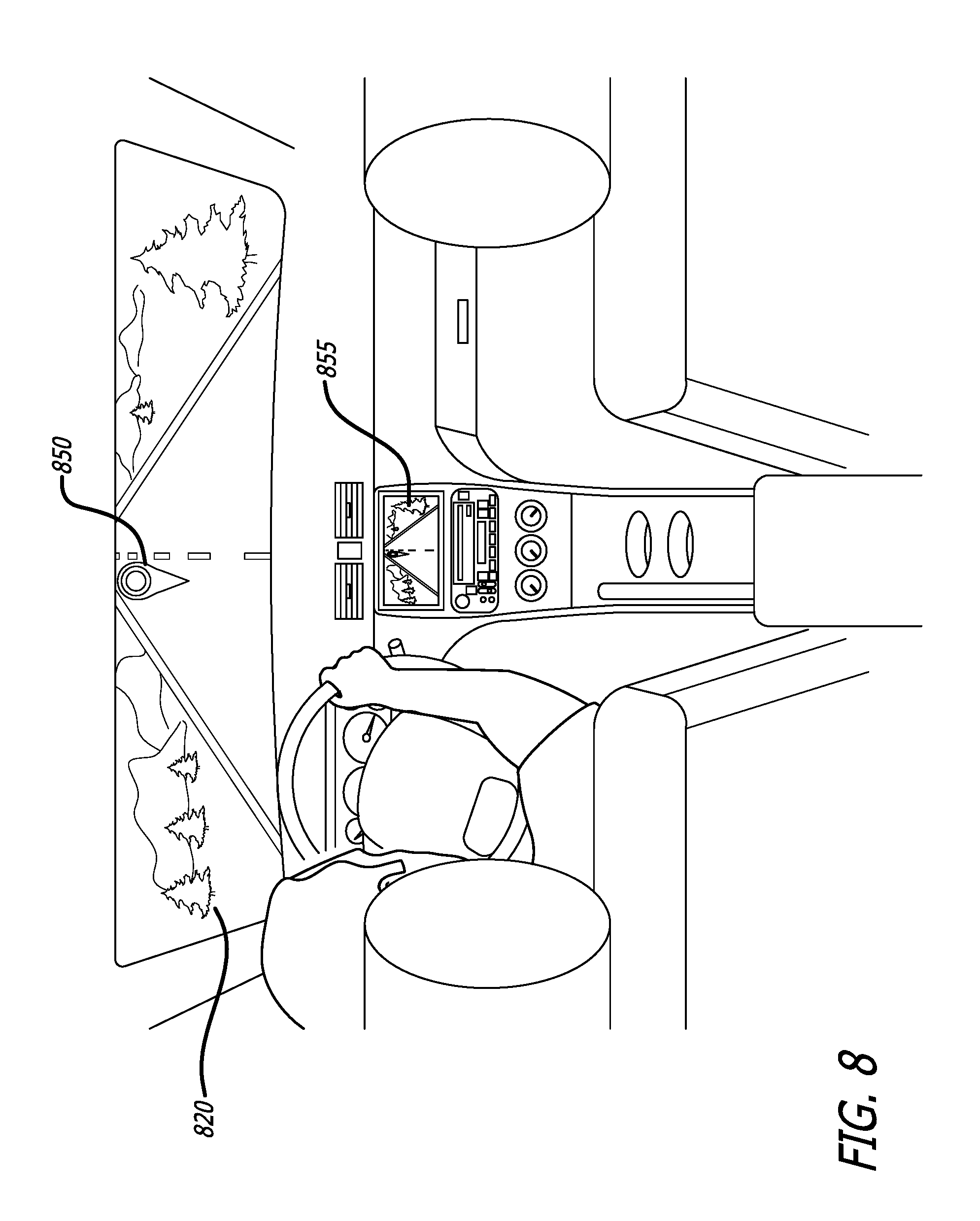
FIG. 8 illustrates an example for explaining a viewing system including an active transparency modulation film used to control the viewability of an automotive head-up display (HUD) according to one embodiment. In this embodiment, the active transparency modulation film is applied to the inside of the automobile windshield 820 to display an augmented reality image 850. In addition the HUD may display content 855 on a display screen, or may alternatively present content 855 as augmented reality content.
By virtue of incorporating the active transparency modulation film, it is possible to avoid ghosting of the information presented by the HUD, and to reduce the illumination perceived by the driver from particularly bright spots, both of which make the information presented by the HUD more readable without obstructing the driver's vision of the road ahead, and improving the driver's vision of the road ahead.
Turning to FIGS. 9A-9E, an active transparency modulation film may be incorporated into transparent display cases (e.g., 900a) holding objects (e.g., 910a), thereby creating enclosures that allow a change of appearance of the objects contained inside the display cases. In FIGS. 9A-9E, each of the display cases 900a-E include an active transparency modulation film that may be comprised of PDLC.
Thus, as shown in FIG. 9A, a transparent display 900a displays object 910a. In one embodiment, display 900a may be cylindrical. In FIG. 9B, the active transparency modulation film on the display 900b is controlled to create mask 910b for the object, whereby the mask defines pixels for which light is blocked and the object appears opaque. In FIGS. 9C-9E, for displays 900c, 900d, 900e, different light textures are projected onto the masked object of FIG. 9B. The light textures are projected by imaging devices or projectors (not shown) to create different skins 910C, 910D, 910E for the objects.
FIG. 11 illustrates a flow diagram for explaining an example method for active transparency modulation according to an embodiment herein, and particularly how bright areas may be masked in a lens incorporating an active transparency modulation film. It should be understood that in embodiments involving a mask, masked areas may be given a predetermined transmissivity, such as 40%.
In this regard, the following embodiments may be described as a process 1100, which is usually depicted as a flowchart, a flow diagram, a structure diagram, or a block diagram. Although a flowchart may describe the operations as a sequential process, many of the operations can be performed in parallel or concurrently. In addition, the order of the operations may be re-arranged. A process is terminated when its operations are completed. A process corresponds to a method, procedure, etc.
In some embodiments discussed herein, GPU depth buffers are used for direct control of an active transparency modulation film. However, in situations where GPU depth buffer data is unavailable, process 1100 may be used to calculate an outline of content to be displayed.
At block 1101, the image content to be displayed is loaded in a memory, such as SRAM, accessible by one or more processors (e.g., GPU, video coprocessor, electrochromic layer control coprocessor). In addition, the mask image containing the states of the pixels of the active transparency modulation layer is first initialized at zero (e.g., the `off` position). At block 1102, color channels are discarded. For example, the image may be transformed into a binary, black and white image based on entropy, cluster and statistical analysis. At block 1103, the application processor then separates the bright field (e.g., foreground) component of the image from the dark field component (e.g., background, which is black in one embodiment). In other embodiments, the order of execution of blocks 1102 and 1103 is switched, such that the bright field component of the image is first separated from the dark field component and then the bright field component is transformed into a binary, black and white image based on entropy, cluster and statistical analysis. The morphology of the black and white images is then analyzed to detect separated or disconnected objects in the image. Pixels of the active transparency modulation film associated with each separated object are then grouped and labeled. At block 1104, each individual pixel group may then be used to calculate the alpha value associated with that group and the pixels that represent a convex hull of the group. After these parameters are calculated, the corresponding pixels on the active transparency modulation film are modulated accordingly by the electrochromic layer control coprocessor at block 1105.
With respect to convex hulls, generally, a convex hull or convex envelope may be considered a set of all convex combinations of points in a set of points. The convex hull may be generated from a set of edges in an image. For example, only the outlying pixels of desired opaque areas may be determined, and the opaque silhouetted image is taken as a convex hull of the image. When the set of points is a bounded subset of a Euclidean plane, the convex hull may be visualized as the shape enclosed by a rubber band stretched around the set of points. Examples of convex hulls are illustrated in FIGS. 10A-D. In particular, object 1010 has convex hull 1020 in FIG. 10A. In FIG. 10B, the outlying points of the object and the convex hull have the same silhouette (outline) 1030. In the FIG. 10C, one corner of the object from FIG. 10B has been folded along the dashed line, and therefore object 1045 has convex hull 1040. In FIG. 10D, object 1055 has convex hull 1050.
Although the embodiments of FIGS. 10 and 11 specifically rely on convex hulls to segment an image and calculate an image outline, in other embodiments, any image segmentation technique may be used. In this regard, convex hull based segmentation may be considered one example of an image segmentation technique. Other examples may include thresholding, clustering, and using statistical properties of display bitmap pixels. Edge detection algorithms may also be used to calculate the image outline or boundary. As discussed herein, the outline generated by the image segmentation technique allows the system to "blank out" the silhouette of the displayed image (e.g., as illustrated in FIG. 5).
Thus, the present disclosure has a number of aspects, which aspects may be practiced alone or in various combinations or sub-combinations, as desired. While certain preferred embodiments have been disclosed and described herein for purposes of illustration and not for purposes of limitation, it will be understood by those skilled in the art that various changes in form and detail may be made therein without departing from the spirit and scope of the disclosure. Therefore, it must be understood that the illustrated embodiments have been set forth only for the purposes of example and should not be taken as limiting the disclosure as defined by any claims in any subsequent application claiming priority to this application.
For example, notwithstanding the fact that the elements of such a claim may be set forth in a certain combination, it must be expressly understood that the disclosure includes other combinations of fewer, more or different elements. Therefore, although elements may be described above as acting in certain combinations and even subsequently claimed as such, it is to be expressly understood that one or more elements from a claimed combination can in some cases be excised from the combination and that such claimed combination may be directed to a subcombination or variation of a subcombination.
The words used in this specification to describe the disclosure and its various embodiments are to be understood not only in the sense of their commonly defined meanings, but to include by special definition in this specification structure, material or acts beyond the scope of the commonly defined meanings. Thus, if an element can be understood in the context of this specification as including more than one meaning, then its use in a subsequent claim must be understood as being generic to all possible meanings supported by the specification and by the word itself.
The definitions of the words or elements of any claims in any subsequent application claiming priority to this application should be, therefore, defined to include not only the combination of elements which are literally set forth, but all equivalent structure, material or acts for performing substantially the same function in substantially the same way to obtain substantially the same result. In this sense, it is therefore contemplated that an equivalent substitution of two or more elements may be made for any one of the elements in such claims below or that a single element may be substituted for two or more elements in such a claim.
* * * * *
References
D00000
D00001
D00002
D00003
D00004
D00005
D00006
D00007
D00008
D00009
XML
uspto.report is an independent third-party trademark research tool that is not affiliated, endorsed, or sponsored by the United States Patent and Trademark Office (USPTO) or any other governmental organization. The information provided by uspto.report is based on publicly available data at the time of writing and is intended for informational purposes only.
While we strive to provide accurate and up-to-date information, we do not guarantee the accuracy, completeness, reliability, or suitability of the information displayed on this site. The use of this site is at your own risk. Any reliance you place on such information is therefore strictly at your own risk.
All official trademark data, including owner information, should be verified by visiting the official USPTO website at www.uspto.gov. This site is not intended to replace professional legal advice and should not be used as a substitute for consulting with a legal professional who is knowledgeable about trademark law.