Systems and methods of legibly capturing vehicle markings
Han , et al. Dec
U.S. patent number 10,521,675 [Application Number 15/269,144] was granted by the patent office on 2019-12-31 for systems and methods of legibly capturing vehicle markings. This patent grant is currently assigned to Digital Ally, Inc.. The grantee listed for this patent is Digital Ally, Inc.. Invention is credited to Jeremy A. Dick, Peng Han.


| United States Patent | 10,521,675 |
| Han , et al. | December 31, 2019 |
Systems and methods of legibly capturing vehicle markings
Abstract
A system and method for legible capture of vehicle identification data includes video cameras and a computer. Recording attributes such as gain, gain shutter speed, and white balance are adjusted throughout ranges to maximize the likelihood of capturing at least one frame in which characters, such as those on the license plate, are legible. Successful capture of a legible frame may trigger storage of the data, while unsuccessful capture may trigger additional scans.
| Inventors: | Han; Peng (Overland Park, KS), Dick; Jeremy A. (Olathe, KS) | ||||||||||
|---|---|---|---|---|---|---|---|---|---|---|---|
| Applicant: |
|
||||||||||
| Assignee: | Digital Ally, Inc. (Lenexa,
KS) |
||||||||||
| Family ID: | 61620495 | ||||||||||
| Appl. No.: | 15/269,144 | ||||||||||
| Filed: | September 19, 2016 |
Prior Publication Data
| Document Identifier | Publication Date | |
|---|---|---|
| US 20180082142 A1 | Mar 22, 2018 | |
| Current U.S. Class: | 1/1 |
| Current CPC Class: | H04N 5/77 (20130101); H04N 7/183 (20130101); G06K 9/3258 (20130101); G06K 9/00785 (20130101); H04N 5/232 (20130101); H04N 9/8205 (20130101); G06K 2209/15 (20130101) |
| Current International Class: | G06K 9/00 (20060101); H04N 7/18 (20060101); H04N 9/82 (20060101); H04N 5/77 (20060101); H04N 5/232 (20060101); G06K 9/32 (20060101) |
| Field of Search: | ;348/148 |
References Cited [Referenced By]
U.S. Patent Documents
| 4409670 | October 1983 | Herndon et al. |
| 4789904 | December 1988 | Peterson |
| 4863130 | September 1989 | Marks, Jr. |
| 4918473 | April 1990 | Blackshear |
| 5027104 | June 1991 | Reid |
| 5096287 | March 1992 | Kaikinami et al. |
| 5111289 | May 1992 | Lucas et al. |
| 5289321 | February 1994 | Secor |
| 5381155 | January 1995 | Gerber |
| 5408330 | April 1995 | Squicciarii et al. |
| 5446659 | August 1995 | Yamawaki |
| 5453939 | September 1995 | Hoffman et al. |
| 5473501 | December 1995 | Claypool |
| 5473729 | December 1995 | Bryant et al. |
| 5479149 | December 1995 | Pike |
| 5497419 | March 1996 | Hill |
| 5526133 | June 1996 | Paff |
| 5585798 | December 1996 | Yoshioka et al. |
| 5642285 | June 1997 | Woo et al. |
| 5668675 | September 1997 | Fredricks |
| 5689442 | November 1997 | Swanson et al. |
| 5742336 | April 1998 | Lee |
| 5752632 | May 1998 | Sanderson et al. |
| 5798458 | August 1998 | Monroe |
| 5815093 | September 1998 | Kikinis |
| 5850613 | December 1998 | Bullecks |
| 5878283 | March 1999 | House et al. |
| 5886739 | March 1999 | Winningstad |
| 5890079 | March 1999 | Levine |
| 5926210 | July 1999 | Hackett et al. |
| 5962806 | October 1999 | Coakley et al. |
| 5978017 | November 1999 | Tino |
| 5983161 | November 1999 | Lemelson et al. |
| 5996023 | November 1999 | Winter et al. |
| 6008841 | December 1999 | Charlson |
| 6028528 | February 2000 | Lorenzetti et al. |
| 6052068 | April 2000 | Price R-W et al. |
| 6097429 | August 2000 | Seeley et al. |
| 6100806 | August 2000 | Gaukel |
| 6121881 | September 2000 | Bieback et al. |
| 6141609 | October 2000 | Herdeg et al. |
| 6141611 | October 2000 | Mackey et al. |
| 6163338 | December 2000 | Johnson et al. |
| 6175300 | January 2001 | Kendrick |
| 6298290 | October 2001 | Abe et al. |
| 6310541 | October 2001 | Atkins |
| 6314364 | November 2001 | Nakamura |
| 6324053 | November 2001 | Kamijo |
| 6326900 | December 2001 | Deline et al. |
| 6333694 | December 2001 | Pierce et al. |
| 6333759 | December 2001 | Mazzilli |
| 6370475 | April 2002 | Breed et al. |
| RE37709 | May 2002 | Dukek |
| 6389340 | May 2002 | Rayner |
| 6396403 | May 2002 | Haner |
| 6405112 | June 2002 | Rayner |
| 6449540 | September 2002 | Rayner |
| 6452572 | September 2002 | Fan et al. |
| 6490409 | December 2002 | Walker |
| 6518881 | February 2003 | Monroe |
| 6525672 | February 2003 | Chainer et al. |
| 6546119 | April 2003 | Ciolli et al. |
| 6560463 | May 2003 | Santhoff |
| 6563532 | May 2003 | Strub et al. |
| 6591242 | July 2003 | Karp et al. |
| 6681195 | January 2004 | Poland et al. |
| 6690268 | February 2004 | Schofield et al. |
| 6697103 | February 2004 | Fernandez et al. |
| 6718239 | April 2004 | Rayer |
| 6727816 | April 2004 | Helgeson |
| 6748792 | June 2004 | Freund et al. |
| 6823621 | November 2004 | Goffried |
| 6831556 | December 2004 | Boykin |
| 6856873 | February 2005 | Breed et al. |
| 6877434 | April 2005 | McNulty, Jr. |
| 6883694 | April 2005 | Abelow |
| 6950122 | September 2005 | Mirabile |
| 6970183 | November 2005 | Monroe |
| 7012632 | March 2006 | Freeman et al. |
| 7034683 | April 2006 | Ghazarian |
| D520738 | May 2006 | Tarantino |
| 7038590 | May 2006 | Hoffman et al. |
| 7071969 | July 2006 | Stimson, III |
| 7088387 | August 2006 | Freeman et al. |
| 7119832 | October 2006 | Blanco et al. |
| 7126472 | October 2006 | Kraus et al. |
| 7147155 | December 2006 | Weekes |
| 7180407 | February 2007 | Guo et al. |
| 7190822 | March 2007 | Gammenthaler |
| 7363742 | April 2008 | Nerheim |
| 7371021 | May 2008 | Ross et al. |
| 7421024 | September 2008 | Castillo |
| 7436143 | October 2008 | Lakshmanan et al. |
| 7436955 | October 2008 | Yan et al. |
| 7448996 | November 2008 | Khanuja et al. |
| 7456875 | November 2008 | Kashiwa |
| 7496140 | February 2009 | Winningstad et al. |
| 7500794 | March 2009 | Clark |
| 7508941 | March 2009 | O'Toole, Jr. et al. |
| 7511737 | March 2009 | Singh |
| 7536457 | May 2009 | Miller |
| 7539533 | May 2009 | Tran |
| 7561037 | July 2009 | Monroe |
| 7594305 | September 2009 | Moore |
| 7602301 | October 2009 | Stirling et al. |
| 7602597 | October 2009 | Smith et al. |
| 7631452 | December 2009 | Brundula et al. |
| 7656439 | February 2010 | Manico et al. |
| 7659827 | February 2010 | Gunderson et al. |
| 7680947 | March 2010 | Nicholl et al. |
| 7697035 | April 2010 | Suber, III et al. |
| 7701692 | April 2010 | Smith et al. |
| 7778004 | August 2010 | Nerheim et al. |
| 7804426 | September 2010 | Etcheson |
| 7806525 | October 2010 | Howell et al. |
| 7853944 | December 2010 | Choe |
| 7944676 | May 2011 | Smith et al. |
| 7984579 | July 2011 | Brundula et al. |
| 8077029 | December 2011 | Daniel et al. |
| 8121306 | February 2012 | Cilia et al. |
| 8175314 | May 2012 | Webster |
| 8269617 | September 2012 | Cook et al. |
| 8314708 | November 2012 | Gunderson et al. |
| 8350907 | January 2013 | Blanco et al. |
| 8356438 | January 2013 | Brundula et al. |
| 8373567 | February 2013 | Denson |
| 8373797 | February 2013 | Isii et al. |
| 8384539 | February 2013 | Denny et al. |
| 8446469 | May 2013 | Blanco et al. |
| 8456293 | June 2013 | Trundle et al. |
| 8508353 | August 2013 | Cook et al. |
| 8559486 | October 2013 | Kitayoshi |
| 8594485 | November 2013 | Brundula |
| 8606492 | December 2013 | Botnen |
| 8676428 | March 2014 | Richardson et al. |
| 8690365 | April 2014 | Williams |
| 8707758 | April 2014 | Keays |
| 8725462 | May 2014 | Jain et al. |
| 8744642 | June 2014 | Nemat-Nasser et al. |
| 8780205 | July 2014 | Boutell et al. |
| 8781292 | July 2014 | Ross et al. |
| 8805431 | August 2014 | Vasavada et al. |
| 8849501 | September 2014 | Cook et al. |
| 8854199 | October 2014 | Cook et al. |
| 8887208 | November 2014 | Merrit et al. |
| 8890954 | November 2014 | O'Donnell et al. |
| 8930072 | January 2015 | Lambert et al. |
| 8934045 | January 2015 | Kam et al. |
| 8989914 | March 2015 | Nemat-Nasser et al. |
| 8996234 | March 2015 | Tamari et al. |
| 8996240 | March 2015 | Plante |
| 9002313 | April 2015 | Sink et al. |
| 9003474 | April 2015 | Smith |
| 9058499 | June 2015 | Smith |
| 9122082 | September 2015 | Abreau |
| 9123241 | September 2015 | Grigsby et al. |
| 9164543 | October 2015 | Minn et al. |
| 9253452 | February 2016 | Ross et al. |
| 9518727 | December 2016 | Markle et al. |
| 9591255 | March 2017 | Sakiewica et al. |
| 9728228 | August 2017 | Palmer et al. |
| 9841259 | December 2017 | Phillips et al. |
| 2001/0033661 | October 2001 | Prokoski |
| 2002/0013517 | January 2002 | West et al. |
| 2002/0019696 | February 2002 | Kruse |
| 2002/0032510 | March 2002 | Tumball et al. |
| 2002/0044065 | April 2002 | Quist et al. |
| 2002/0049881 | April 2002 | Sugimura |
| 2002/0084130 | July 2002 | Der Gazarian et al. |
| 2002/0131768 | September 2002 | Gammenthaler |
| 2002/0135336 | September 2002 | Zhou et al. |
| 2002/0159434 | October 2002 | Gosior et al. |
| 2002/0191952 | December 2002 | Fiore et al. |
| 2003/0040917 | February 2003 | Fiedler |
| 2003/0080713 | May 2003 | Kirmuss |
| 2003/0080878 | May 2003 | Kirmuss |
| 2003/0081121 | May 2003 | Kirmuss |
| 2003/0081934 | May 2003 | Kirmuss |
| 2003/0081935 | May 2003 | Kirmuss |
| 2003/0081942 | May 2003 | Melnyk et al. |
| 2003/0095688 | May 2003 | Kirmuss |
| 2003/0106917 | June 2003 | Shelter et al. |
| 2003/0133018 | July 2003 | Ziemkowski |
| 2003/0151510 | August 2003 | Quintana et al. |
| 2003/0184674 | October 2003 | Manico et al. |
| 2003/0185417 | October 2003 | Alattar et al. |
| 2003/0215010 | November 2003 | Kashiwa |
| 2003/0215114 | November 2003 | Kyle |
| 2003/0222982 | December 2003 | Hamdan et al. |
| 2004/0008255 | January 2004 | Lewellen |
| 2004/0043765 | March 2004 | Tolhurst |
| 2004/0143373 | June 2004 | Ennis |
| 2004/0145457 | July 2004 | Schofield et al. |
| 2004/0150717 | August 2004 | Page et al. |
| 2004/0168002 | August 2004 | Accarie et al. |
| 2004/0199785 | October 2004 | Pederson |
| 2004/0223054 | November 2004 | Rotholtz |
| 2004/0243734 | December 2004 | Kitagawa et al. |
| 2004/0267419 | December 2004 | Jing |
| 2005/0030151 | February 2005 | Singh |
| 2005/0046583 | March 2005 | Richards |
| 2005/0050266 | March 2005 | Haas et al. |
| 2005/0068169 | March 2005 | Copley et al. |
| 2005/0068417 | March 2005 | Kreiner |
| 2005/0083404 | April 2005 | Pierce et al. |
| 2005/0094966 | May 2005 | Elberbaum |
| 2005/0100329 | May 2005 | Lao et al. |
| 2005/0101334 | May 2005 | Brown et al. |
| 2005/0134966 | May 2005 | Burgner |
| 2005/0132200 | June 2005 | Jaffe et al. |
| 2005/0151852 | July 2005 | Jomppanen |
| 2005/0035161 | August 2005 | Shioda |
| 2005/0185438 | August 2005 | Ching |
| 2005/0206532 | September 2005 | Lock |
| 2005/0206741 | September 2005 | Raber |
| 2005/0228234 | October 2005 | Yang |
| 2005/0232469 | October 2005 | Schofield et al. |
| 2005/0243171 | November 2005 | Ross, Sr. et al. |
| 2005/0258942 | November 2005 | Mansseh et al. |
| 2006/0009238 | January 2006 | Stanco et al. |
| 2006/0028811 | February 2006 | Ross, Jr. et al. |
| 2006/0055786 | March 2006 | Olilla |
| 2006/0082730 | April 2006 | Franks |
| 2006/0158968 | July 2006 | Vanman et al. |
| 2006/0164220 | July 2006 | Harter, Jr. et al. |
| 2006/0164534 | July 2006 | Robinson et al. |
| 2006/0170770 | August 2006 | MacCarthy |
| 2006/0176149 | August 2006 | Douglas |
| 2006/0183505 | August 2006 | Willrich |
| 2006/0193749 | August 2006 | Ghazarian et al. |
| 2006/0203090 | September 2006 | Wang et al. |
| 2006/0220826 | October 2006 | Rast |
| 2006/0225253 | October 2006 | Bates |
| 2006/0244601 | November 2006 | Nishimura |
| 2006/0256822 | November 2006 | Kwong et al. |
| 2006/0267773 | November 2006 | Roque |
| 2006/0270465 | November 2006 | Lee et al. |
| 2006/0271287 | November 2006 | Gold et al. |
| 2006/0274166 | December 2006 | Lee et al. |
| 2006/0274828 | December 2006 | Siemens et al. |
| 2006/0276200 | December 2006 | Radhakrishnan et al. |
| 2006/0278705 | December 2006 | Hedley |
| 2006/0282021 | December 2006 | DeVaul et al. |
| 2006/0287821 | December 2006 | Lin |
| 2006/0293571 | December 2006 | Bao et al. |
| 2007/0021134 | January 2007 | Liou |
| 2007/0064108 | March 2007 | Haler |
| 2007/0067079 | March 2007 | Kosugi |
| 2007/0091557 | April 2007 | Kim et al. |
| 2007/0102508 | May 2007 | Mcintosh |
| 2007/0117083 | May 2007 | Winneg et al. |
| 2007/0132567 | June 2007 | Schofield et al. |
| 2007/0152811 | July 2007 | Anderson |
| 2007/0172053 | July 2007 | Poirier |
| 2007/0177023 | August 2007 | Beuhler et al. |
| 2007/0195939 | August 2007 | Sink et al. |
| 2007/0199076 | August 2007 | Rensin et al. |
| 2007/0213088 | September 2007 | Sink |
| 2007/0229350 | October 2007 | Scalisi et al. |
| 2007/0257781 | November 2007 | Denson |
| 2007/0257782 | November 2007 | Etcheson |
| 2007/0257804 | November 2007 | Gunderson et al. |
| 2007/0257815 | November 2007 | Gunderson et al. |
| 2007/0260361 | November 2007 | Etcheson |
| 2007/0268158 | November 2007 | Gunderson et al. |
| 2007/0271105 | November 2007 | Gunderson et al. |
| 2007/0274705 | November 2007 | Kashiwa |
| 2007/0277352 | December 2007 | Maron et al. |
| 2007/0285222 | December 2007 | Zadnikar |
| 2007/0287425 | December 2007 | Bates |
| 2007/0297320 | December 2007 | Brummette et al. |
| 2008/0001735 | January 2008 | Tran |
| 2008/0002031 | January 2008 | Cana et al. |
| 2008/0002599 | February 2008 | Denny et al. |
| 2008/0030580 | February 2008 | Kashhiawa et al. |
| 2008/0042825 | February 2008 | Denny et al. |
| 2008/0043736 | February 2008 | Stanley |
| 2008/0049830 | February 2008 | Richardson |
| 2008/0063252 | March 2008 | Dobbs et al. |
| 2008/0084473 | April 2008 | Romanowich |
| 2008/0100705 | May 2008 | Kister et al. |
| 2008/0122603 | May 2008 | Piante et al. |
| 2008/0129518 | June 2008 | Carlton-Foss |
| 2008/0143481 | June 2008 | Abraham et al. |
| 2008/0144705 | June 2008 | Rackin et al. |
| 2008/0169929 | July 2008 | Albertson et al. |
| 2008/0170130 | July 2008 | Ollila et al. |
| 2008/0175565 | July 2008 | Takakura et al. |
| 2008/0211906 | September 2008 | Lovric |
| 2008/0222849 | September 2008 | Lavoie |
| 2008/0239064 | October 2008 | Iwasaki |
| 2008/0246656 | October 2008 | Ghazarian |
| 2008/0266118 | October 2008 | Pierson et al. |
| 2008/0307435 | December 2008 | Rehman |
| 2008/0316314 | December 2008 | Bedell et al. |
| 2009/0002491 | January 2009 | Haler |
| 2009/0002556 | January 2009 | Manapragada et al. |
| 2009/0027499 | January 2009 | Nicholl |
| 2009/0052685 | February 2009 | Cilia et al. |
| 2009/0070820 | March 2009 | Li |
| 2009/0085740 | April 2009 | Klein et al. |
| 2009/0109292 | April 2009 | Ennis |
| 2009/0122142 | May 2009 | Shapley |
| 2009/0135007 | May 2009 | Donovan et al. |
| 2009/0169068 | July 2009 | Okamoto |
| 2009/0189981 | July 2009 | Siann et al. |
| 2009/0195686 | August 2009 | Shintani |
| 2009/0207252 | August 2009 | Raghunath |
| 2009/0213204 | August 2009 | Wong |
| 2009/0225189 | September 2009 | Morin |
| 2009/0243794 | October 2009 | Morrow |
| 2009/0251545 | October 2009 | Shekarri et al. |
| 2009/0252486 | October 2009 | Ross, Jr. et al. |
| 2009/0276708 | November 2009 | Smith et al. |
| 2009/0294538 | December 2009 | Wihlborg et al. |
| 2009/0324203 | December 2009 | Wiklof |
| 2010/0045798 | February 2010 | Sugimoto |
| 2010/0050734 | March 2010 | Chou |
| 2010/0060747 | March 2010 | Woodman |
| 2010/0097221 | April 2010 | Kreiner et al. |
| 2010/0106707 | April 2010 | Brown et al. |
| 2010/0118147 | May 2010 | Dorneich et al. |
| 2010/0122435 | May 2010 | Markham |
| 2010/0123779 | May 2010 | Snyder et al. |
| 2010/0177193 | July 2010 | Flores |
| 2010/0177891 | July 2010 | Keidar et al. |
| 2010/0188201 | July 2010 | Cook et al. |
| 2010/0191411 | July 2010 | Cook et al. |
| 2010/0194885 | August 2010 | Plaster |
| 2010/0217836 | August 2010 | Rofougaran |
| 2010/0238009 | September 2010 | Cook et al. |
| 2010/0238262 | September 2010 | Kurtz et al. |
| 2010/0242076 | September 2010 | Potesta et al. |
| 2010/0265331 | October 2010 | Tanaka |
| 2010/0274816 | October 2010 | Guzik |
| 2010/0287473 | November 2010 | Recesso et al. |
| 2011/0006151 | January 2011 | Beard |
| 2011/0018998 | January 2011 | Guzik |
| 2011/0050904 | March 2011 | Anderson |
| 2011/0069151 | March 2011 | Orimoto |
| 2011/0084820 | April 2011 | Walter et al. |
| 2011/0094003 | April 2011 | Spiewak et al. |
| 2011/0098924 | April 2011 | Baladeta et al. |
| 2011/0129151 | June 2011 | Saito |
| 2011/0157759 | June 2011 | Smith et al. |
| 2011/0187895 | August 2011 | Cheng et al. |
| 2011/0261176 | October 2011 | Monaghan, Sr. et al. |
| 2011/0281547 | November 2011 | Cordero |
| 2011/0301971 | December 2011 | Roesch et al. |
| 2011/0314401 | December 2011 | Salisbury et al. |
| 2012/0038689 | February 2012 | Ishii |
| 2012/0056722 | March 2012 | Kawaguchi |
| 2012/0063736 | March 2012 | Simmons et al. |
| 2012/0120258 | May 2012 | Boutell et al. |
| 2012/0162436 | June 2012 | Cordell et al. |
| 2012/0188345 | July 2012 | Salow |
| 2012/0189286 | July 2012 | Takayama et al. |
| 2012/0195574 | August 2012 | Wallance |
| 2012/0230540 | September 2012 | Calman et al. |
| 2012/0257320 | October 2012 | Brundula et al. |
| 2012/0268259 | October 2012 | Igel et al. |
| 2012/0276954 | November 2012 | Kowalsky |
| 2013/0021153 | January 2013 | Keays |
| 2013/0033610 | February 2013 | Osborn |
| 2013/0035602 | February 2013 | Gemer |
| 2013/0080836 | March 2013 | Stergiou et al. |
| 2013/0096731 | April 2013 | Tamari et al. |
| 2013/0125000 | May 2013 | Flischhauser et al. |
| 2013/0148295 | June 2013 | Minn et al. |
| 2013/0222640 | August 2013 | Baek et al. |
| 2013/0225309 | August 2013 | Bentley et al. |
| 2013/0285232 | October 2013 | Sheth |
| 2013/0300563 | November 2013 | Glaze |
| 2013/0343571 | December 2013 | Lee |
| 2014/0037262 | February 2014 | Sako |
| 2014/0049636 | February 2014 | O'Donnell et al. |
| 2014/0092299 | April 2014 | Phillips et al. |
| 2014/0094992 | April 2014 | Lambert et al. |
| 2014/0098453 | April 2014 | Brundula et al. |
| 2014/0140575 | May 2014 | Wolf |
| 2014/0170602 | June 2014 | Reed |
| 2014/0176750 | June 2014 | Pajak |
| 2014/0192194 | July 2014 | Bedell et al. |
| 2014/0195105 | July 2014 | Lambert et al. |
| 2014/0195272 | July 2014 | Sadiq et al. |
| 2014/0210625 | July 2014 | Nemat-Nasser |
| 2014/0218544 | August 2014 | Senot et al. |
| 2014/0227671 | August 2014 | Olmstead et al. |
| 2014/0311215 | October 2014 | Keays et al. |
| 2014/0341532 | November 2014 | Marathe |
| 2014/0355951 | December 2014 | Tabak |
| 2015/0050003 | February 2015 | Ross et al. |
| 2015/0050345 | February 2015 | Smyth et al. |
| 2015/0051502 | February 2015 | Ross |
| 2015/0053776 | March 2015 | Rose et al. |
| 2015/0078727 | March 2015 | Ross et al. |
| 2015/0088335 | March 2015 | Lambert et al. |
| 2015/0103246 | April 2015 | Phillips et al. |
| 2015/0317368 | November 2015 | Rhoads et al. |
| 2015/0332424 | November 2015 | Kane et al. |
| 2015/0358549 | December 2015 | Cho |
| 2016/0042767 | February 2016 | Araya et al. |
| 2016/0104508 | April 2016 | Chee et al. |
| 2016/0127695 | May 2016 | Zhang et al. |
| 2016/0165192 | June 2016 | Saatchi et al. |
| 2016/0364621 | December 2016 | Hill et al. |
| 2017/0070659 | March 2017 | Kievsky |
| 2017/0195636 | July 2017 | Yokomitsu et al. |
| 2017/0230605 | August 2017 | Han et al. |
| 2017/0237950 | August 2017 | Araya et al. |
| 2017/0244884 | August 2017 | Burtey |
| 2017/0277700 | September 2017 | Davis et al. |
| 2017/0287523 | October 2017 | Hodulik et al. |
| 2018/0023910 | January 2018 | Kramer |
| 2018/0050800 | February 2018 | Boykin et al. |
| 102010019451 | Nov 2011 | DE | |||
| 2479993 | Jul 2012 | EP | |||
| 2273624 | Jun 1994 | GB | |||
| 2320389 | May 1998 | GB | |||
| 2343252 | May 2000 | GB | |||
| 2351055 | Dec 2000 | GB | |||
| 2417151 | Feb 2006 | GB | |||
| 2425427 | Oct 2006 | GB | |||
| 2455885 | Jul 2009 | GB | |||
| 2485804 | May 2012 | GB | |||
| 20090923 | Sep 2010 | IE | |||
| 294188 | Sep 1993 | JP | |||
| 153298 | Jun 1996 | JP | |||
| 198858 | Jul 1997 | JP | |||
| 10076880 | Mar 1998 | JP | |||
| 210395 | Jul 1998 | JP | |||
| 2000137263 | May 2000 | JP | |||
| 2005119631 | May 2005 | JP | |||
| 20-0236817 | Aug 2001 | KR | |||
| 1050897 | Jul 2011 | KR | |||
| 2383915 | Mar 2010 | RU | |||
| 107851 | Aug 2011 | RU | |||
| 124780 | Feb 2013 | RU | |||
| 9005076 | May 1990 | WO | |||
| 9738526 | Oct 1997 | WO | |||
| 9831146 | Jul 1998 | WO | |||
| 9948308 | Sep 1999 | WO | |||
| 0039556 | Jul 2000 | WO | |||
| 0051360 | Aug 2000 | WO | |||
| 0123214 | Apr 2001 | WO | |||
| 0249881 | Jun 2002 | WO | |||
| 02095757 | Nov 2002 | WO | |||
| 03049446 | Jun 2003 | WO | |||
| 2004036926 | Apr 2004 | WO | |||
| 2009013526 | Jan 2009 | WO | |||
| 2011001180 | Jan 2011 | WO | |||
| 2012037139 | Mar 2012 | WO | |||
| 2012120083 | Sep 2012 | WO | |||
| 2014000161 | Jan 2014 | WO | |||
| 2014052898 | Apr 2014 | WO | |||
Other References
|
Automation Systems Article, Know-How Bank Co. Ltd. Takes Leap Forward as a Company Specializing in R&D and Technology Consulting, published Jan. 2005. cited by applicant . Car Rear View Camera--Multimedia Rear View Mirror--4' LCD color monitor, Retrieved from the Internet: <URL: http://web.archive.org/web/20050209014751/http://laipac.com/multimedia-re- ar-mirror.htm>, Feb. 9, 2005. cited by applicant . ATC Chameleon. Techdad Review [Online] Jun. 19, 2013 [Retrieved on Dec. 30, 2015]. Retrieved from Internet. <URL:http://www.techdadreview.com/2013/06/19atc-chameleon/>. cited by applicant . "Breathalyzer." Wikipedia. Printed Date: Oct. 16, 2014; Date Page Last Modified: Sep. 14, 2014; <http://en.wikipedia.org/wiki/Breathalyzer>. cited by applicant . Dees, Tim; Taser Axon Flex: The next generation of body camera; <http://www.policeone.com/police-products/body-cameras/articles/527231- -0-TASER-Axon-Flex-The-next-generation-of-body-camera/>, Date Posted: Mar. 12, 2012; Date Printed: Oct. 27, 2015. cited by applicant . Brown, TP-LINK TL-WDR3500 Wireless N600 Router Review, Mar. 6, 2013. cited by applicant . Controller Area Network (CAN) Overview, National Instruments White Paper, Aug. 1, 2014. cited by applicant . Daskam, Samuel W., Law Enforcement Armed Robbery Alarm System Utilizing Recorded Voice Addresses via Police Radio Channels, Source: Univ. of Ky, Off of Res and Eng., Serv (UKY BU107), pp. 18-22, 1975. cited by applicant . Digital Ally vs. Taser International, Inc., Case No. 2:16-cv-232 (CJM/TJ); US D. Kan, Defendant Taser International Inc.'s Preliminary Invalidity Contentions, Jul. 5, 2016. cited by applicant . Electronic Times Article, published Feb. 24, 2005. cited by applicant . Supplementary European Search Report dated Sep. 28, 2010 in European Patent Application No. 06803645.8; Applicant: Digital Ally, Inc. cited by applicant . W. Fincham, Data Recorders for Accident Investigation, Monitoring of Driver and Vehicle Performance (Digest No. 1997/122), Publication Date: Apr. 10, 1997, pp. 6/1-6/3. cited by applicant . Frankel, Harry; Riter, Stephen, Bernat, Andrew, Automated Imaging System for Border Control, Source: University of Kentucky, Office of Engineering Services, (Bulletin) UKY BU, pp. 169-173, Aug. 1986. cited by applicant . Freudenrich, Craig, Ph.D.; "How Breathalyzers Work--Why Test?." HowStuff Works. Printed Date: Oct. 16, 2014; Posted Date: Unknown; <http://electronics.howstuffworks.com/gadgets/automotive/breathalyzer1- .htm>. cited by applicant . Hankyung Auto News Article, Know-How Bank's Black Box for Cars "Multi-Black Box," Copyright 2005. cited by applicant . Guide to Bluetooth Security: Recommendations of the National Institute of Standards and Technology, National Institute of Standards and Technology, U.S. Dep't of Commerce, NIST Special Publication 800-121, Revision 1 (Jun. 2012). cited by applicant . ICOP Extreme Wireless Mic, Operation Supplement, Copyright 2008. cited by applicant . ICOP Model 20/20-W Specifications; Enhanced Digital In-Car Video and Audio recording Systems, date: Unknown. cited by applicant . ICOP Mobile DVRS; ICOP Model 20/20-W & ICOP 20/20 Vision, date: Unknown. cited by applicant . Bertomen, Lindsey J., PoliceOne.com News; "Product Review: ICOP Model 20/20-W," May 19, 2009. cited by applicant . ICOP Raytheon JPS communications, Raytheon Model 20/20-W, Raytheon 20120 Vision Digital In-Car Video Systems, date: Unknown. cited by applicant . Overview of the IEEE 802.15.4 standards for Low rate Wireless Personal Area Networks, 2010 7th International Symposium on Wireless Communication Systems (ISWCS), Copyright 2010. cited by applicant . Lewis, S.R., Future System Specifications for Traffic Enforcement Equipment, S.R. 1 Source: IEE Colloquium (Digest), N 252, Publication Date: Nov. 18, 1996, pp. 8/1-8/2. cited by applicant . Kopin Corporation; Home Page; Printed Date: Oct. 16, 2014; Posted Date: Unknown; <http://www.kopin.com>. cited by applicant . Translation of Korean Patent No. 10-1050897, published Jul. 20, 2011. cited by applicant . Lilliput RV 18-50NP 5'' Rear View Mirror TFT LCD Screen with Camera, Retrieved from the Internet: <URL: http://www.case-mod.com/lilliput-rv1850np-rear-view-mirror-tft-lcd-screen- -with-camera-p-1271.html>, Mar. 4, 2005. cited by applicant . Motor Magazine Article, Recreating the Scene of an Accident, published 2005. cited by applicant . New Rearview-Mirror-Based Camera Display Takes the Guesswork Out of Backing Up Retrieved from the Internet: <URL: httb://news.thomasnet.com/fullstory/497750>, Press Release, Oct. 30, 2006. cited by applicant . SIIF Award for Multi Black Box, published Dec. 10, 2004. cited by applicant . Near Field Communication; Sony Corporation; pp. 1-7, Date: Unknown. cited by applicant . Oregon Scientific ATC Chameleon Dual Lens HD Action Camera, http://www.oregonscientificstore.com/Oregon-Scientific-ATC-Chameleon-Dual- -Lens-HD-Action-Camera.data, Date Posted: Unknown; Date Printed: Oct. 13, 2014, pp. 1-4. cited by applicant . "Stalker Press Room--Using In-Car Video, the Internet, and the Cloud to keep police officers safe is the subject of CopTrax live, free webinar." Stalker. Printed Date: Oct. 16, 2014; Posted Date: Jul. 31, 2014. cited by applicant . State of Utah Invitation to Bid State Cooperative Contract; Vendor: ICOP Digital, Inc., Contract No. MA503, Jul. 1, 2008. cited by applicant . Wasson, Brian; "Digital Eyewear for Law Enforcement." Printed Date: Oct. 16, 2014; Posted Date: Dec. 9, 2013; <http://www.wassom.com/digital-eyewear-for-law-enforcement.html>. cited by applicant . X26 Taser, Date Unknown. cited by applicant . Taser International; Taser X26 Specification Sheet, 2003. cited by applicant . Digital Ally First Vu Mountable Digital Camera Video Recorder, http://www.opticsplanet.com/digital-ally-first-vu-mountable-digital-camer- a-video-recorder.html?gclid=CIKohcX05rkCFSIo7AodU0IA0g&ef_id=UjCGEAAAAWGEj- rQF:20130925155534:s, Sep. 25, 2013, Date Posted: Unknown, pp. 1-4. cited by applicant . Drift X170, http://driftinnovation.com/support/firmware-update/x170/, Sep. 26, 2013, Date Posted: Unknown, p. 1. cited by applicant . Dyna Spy Inc. hidden cameras, https://www.dynaspy.com/hidden-cameras/spy-cameras/body-worn-wearable-spy- -cameras, Sep. 26, 2013, Date Posted: Unknown, pp. 1-3. cited by applicant . Ecplaza HY-001HD law enforcement DVR, http://fireeye.en.ecplaza.net/law-enforcement-dvr--238185-1619696.html, Sep. 26, 2013, Date Posted: Unknown, pp. 1-3. cited by applicant . Edesix VideoBadge, http://www.edesix.com/edesix-products, Sep. 26, 2013, Date Posted: Unknown, pp. 1-3. cited by applicant . GoPro Official Website: The World's Most Versatile Camera, http://gopro.com/products/?gclid=CKqHv9jT4rkCFWZk7AodyiAAaQ, Sep. 23, 2013, Date Posted: Unknown, pp. 4-9. cited by applicant . Isaw Advance Hull HD EXtreme, www.isawcam.co.kr, Sep. 26, 2013, Date Posted: Unknown, p. 1. cited by applicant . Kustom Signals VieVu, http://www.kustomsignals.com/index.php/mvideo/vievu, Sep. 26, 2013, Date Posted: Unknown, pp. 1-4. cited by applicant . Lea-Aid Scorpion Micro Recorder Patrol kit,http://www.leacorp.com/products/SCORPION-Micro-Recorder-Patrol-kit.ht- ml, Sep. 26, 2013, Date Posted: Unknown, pp. 1-2. cited by applicant . Looxcie Wearable & mountable streaming video cams, http://www.looxcie.com/overview?gclid=CPbDyv6piq8CFWeFQAodlhXC-w, Sep. 26, 2013, Date Posted: Unknown, pp. 1-4. cited by applicant . Midland XTC HD Video Camera, http://midlandradio.com/Company/xtc100-signup, Sep. 26, 2013, Date Posted: Unknown, pp. 1-3. cited by applicant . Panasonic Handheld AVCCAM HD Recorder/Player, http://www.panasonic.com/business/provideo/ag-hmr10.asp, Sep. 26, 2013, Date Posted: Unknown, pp. 1-2. cited by applicant . Notification of Transmittal of the International Search Report and the Written Opinion of the International Search Authority, or the Declaration dated Jan. 30, 2014, International Application No. PCT/US2013/062415; International Filing dated Sep. 27, 2013, Applicant: Digital Ally, Inc. cited by applicant . Point of View Cameras Military & Police, http://pointofviewcameras.com/military-police, Sep. 26, 2013, Date Posted: Unknown, pp. 1-2. cited by applicant . POV.HD System Digital Video Camera, http://www.vio-pov.com/index.php, Sep. 26, 2013, Date Posted: Unknown, pp. 1-3. cited by applicant . SIV Security in Vehicle Driving Partner, http://www.siv.co.kr/, Sep. 26, 2013, Date Posted: Unknown, p. 1. cited by applicant . Spy Chest Mini Spy Camera / Self Contained Mini camcorder / Audio & Video Recorder, http://www.spytechs.com/spy_cameras/mini-spy-camera.htm, Sep. 26, 2013, Date Posted: Unknown, pp. 1-3. cited by applicant . Stalker VUE Law Enforcement Grade Body Worn Video Camera/Recorder, http://www.stalkerradar.com/law_vue.shtml, Sep. 26, 2013, Date Posted: Unknown, pp. 1-2. cited by applicant . SUV Cam, http://www.elmo.co.jp/suv-cam/en/product/index.html, Sep. 26, 2013, Date Posted: Unknown, p. 1. cited by applicant . TASER AXON Body On Officer Video/Police Body Camera, http://www.taser.com/products/on-officer-video/axon-body-on-officer-video- , Sep. 23, 2013, Date Posted: Unknown, pp. 1-8. cited by applicant . TASER AXON Flex On-Officer Video/Police Video Camera, http://www.taser.com/products/on-officer-video/taser-axon, Sep. 26, 2013, Date Posted: Unknown, pp. 1-8. cited by applicant . Taser Cam Law Enforcement Audio/Video Recorder (gun mounted), http://www.taser.com/products/on-officer-video/taser-cam, Sep. 26, 2013, Date Posted: Unknown, pp. 1-3. cited by applicant . Tide Leader police body worn camera, http://tideleader.en.gongchang.com/product/14899076, Sep. 26, 2013, Date Posted: Unknown, pp. 1-3. cited by applicant . UCorder Pockito Wearable Mini Pocket Camcorder, http://www.ucorder.com/, Sep. 26, 2013, Date Posted: Unknown, p. 1. cited by applicant . Veho MUVI HD, http://veho-uk.fastnet.co.uk/main/shop.aspx?category=CAMMUVIHD, Sep. 26, 2013, Date Posted: Unknown, pp. 1-5. cited by applicant . Veho MUVI portable wireless speaker with dock, http://veho-uk.fastnet.co.uk/main/shop.aspx?category=camcorder, Sep. 26, 2013, Date Posted: Unknown, p. 1. cited by applicant . Vidmic Officer Worn Video & Radio Accessories, http://www.vidmic.com/, Sep. 26, 2013, Date Posted: Unknown, p. 1. cited by applicant . VIEVU Products, http://www.vievu.com/vievu-products/vievu-squared/, Sep. 25, 2013, Date Posted: Unknown, pp. 1-2. cited by applicant . WatchGuard CopVu Wearable Video Camera System, http://watchguardvideo.com/copvu/overview, Sep. 26, 2013, Date Posted: Unknown, pp. 1-2. cited by applicant . Witness Cam headset, http://www.secgru.com/DVR-Witness-Cam-Headset-Video-Recorder-SG-DVR-1-COP- .html, Sep. 26, 2013, Date Posted: Unknown, pp. 1-2. cited by applicant . WolfCom 3rd Eye, X1 A/V Recorder for Police and Military, http://wolfcomusa.com/Products/Products.html, Sep. 26, 2013, Date Posted: Unknown, pp. 1-3. cited by applicant . Notification of Transmittal of the International Search Report and the Written Opinion of the International Search Authority, or the Declaration dated Jan. 14, 2016, International Application No. PCT/US2015/056039; International Filing date Oct. 16, 2015, Applicant: Digital Ally, Inc. cited by applicant . U.S. Appl. No. 13/959,142 Final Office Action dated Jul. 20, 2016. cited by applicant . U.S. Appl. No. 13/959,142 Office Action dated Nov. 3, 2015. cited by applicant . Petition for Inter Partes Review No. 2017-00775, Taser International, Inc. v. Digital Ally Inc., filed Jan. 25, 2017. cited by applicant . International Association of Chiefs of Police Digital Video System Minimum Specifications; Nov. 21, 2008. cited by applicant . Petition for Inter Partes Review No. 2017-00375, Taser International, Inc. v. Digital Ally, Inc., filed Dec. 1, 2013. cited by applicant . Petition for Inter Partes Review No. 2017-00376, Taser International, Inc. v. Digital Ally, Inc., filed Dec. 1, 2013. cited by applicant . Petition for Inter Partes Review No. 2017-00515, Taser International, Inc. v. Digital Ally Inc., filed Jan. 11, 2017. cited by applicant . PCT Patent Application PCT/US16/34345 International Search Report and Written Opinion dated Dec. 29, 2016. cited by applicant . Digital Ally, Inc. vs. Taser International, Inc., Case No. 2:16-cv-020232 (CJM/TJ); US D. Kan, Complaint for Patent Infringement, Jan. 14, 2016. cited by applicant . Digital Ally, Inc. vs. Enforcement video LLC d/b/a Watchguard Video., Case No. 2:16-cv-02349 (CJM/TJ); US D. Kan, Complaint for Patent Infringement, May 27, 2016. cited by applicant . State of Utah Invitation to Bid State Cooperative Contract; Vendor: Kustom Signals Inc., Contract No. MA1991, Apr. 25, 2008. cited by applicant . PCT Patent Application PCT/US17/16383 International Search Report and Written Opinion dated May 4, 2017. cited by applicant . Invalidity Chart for International Publication No. WO2014/000161 Oct. 31, 2017. cited by applicant . Petition for Post Grant Review No. PGR2018-00052, Axon Enterprise, Inc. v. Digital Ally, Inc., filed Mar. 19, 2018. cited by applicant . MPEG-4 Coding of Moving Pictures and Audio ISO/IEC JTC1/SC29/WG11 N4668 dated Mar. 2002. cited by applicant . European Patent Application 15850436.6 Search Report dated May 4, 2018. cited by applicant . Final Written Decision for Inter Partes Review No. 2017-00375, Axon Enterprise Inc. v. Digital Ally, Inc., issued Jun. 1, 2018. cited by applicant . Decision Denying Institution of Post Grant Review for Post Grant Review No. PGR2018-00052, Axon Enterprise, Inc. v. Digital Ally, Inc., issued Oct. 1, 2018. cited by applicant . Asian Wolf High Quality Angel Eye Body Video Spy Camera Recorder System, http://www.asianwolf.com/covert-bodycam-hq-angeleye.html, Sep. 26, 2013, Date Posted: Unknown, pp. 1-3. cited by applicant . Brick House Security Body Worn Cameras / Hidden Cameras / Covert Spy Cameras, http://www.brickhousesecurity.com/body-worn-covert-spy-cameras.h- tml?sf=0#sortblock&CMPID=PD_Google_%22body+camera%22&utm_source=google&utm- _medium=cpc&utm_term=%22body+camera%22&mm_campaign=876a94ea5dd198a8c5dc3d1- e67eccb34&keyword=%22body+camera%. cited by applicant . Amazon.com wearable camcorders, http://www.amazon.com/s/ref=nb_sb_ss_i_0_4?url=search-alias%3Dphoto&field- -keywords=wearable+camcorder&x=0&y=0&sprefix=wear, Sep. 26, 2013, Date Posted: Unknown, pp. 1-4. cited by applicant . Notification of Transmittal of the International Search Report and the Written Opinion of the International Searching Authority, or the Declaration dated Feb. 4, 2016; International Application No. PCT/US2015/056052; International Filing Date: Oct. 16, 2015; Applicant: Digital Ally, Inc . cited by applicant . http:/ /www.k-h-b.com/board/board.php?board=products01&comand=body&no=1, Current State of Technology Held by the Company, Copyright 2005. cited by applicant . City of Pomona Request for Proposals for Mobile Video Recording System for Police Vehicles, dated prior to Apr. 4, 2013. cited by applicant . http://www.k-h-b.com/sub1_02.html, Copyright 2005. cited by applicant . Renstrom, Joell; "Tiny 3D Projectors Allow You to Transmit Holograms From a Cell Phone." Giant Freakin Robot. Printed Date: Oct. 16, 2014; Posted Date: Jun. 13, 2014; <http://www.giantfreakinrobot.com/sci/coming-3d-projectors-transmit-ho- lograms-cell-phone.html>. cited by applicant . Request for Comment 1323 of the Internet Engineering Task Force, TCP Extensions for High Performance, Date: May 1992. cited by applicant . RevealMedia RS3-SX high definition video recorder, http://www.revealmedia.com/buy-t166/cameras/rs3-sx.aspx, Sep. 26, 2013, Date Posted: Unknown, pp. 1-2. cited by applicant . Scorpion Micro DV Video Audio Recorder, http://www.leacorp.com/scorpion-micro-dv-video-audio-recorder/, Sep. 26, 2013, Date Posted: Unknown, pp. 1-3. cited by applicant. |
Primary Examiner: Ustaris; Joseph G
Assistant Examiner: Shahnami; Amir
Attorney, Agent or Firm: Erise IP, P.A.
Claims
Having thus described various embodiments of the invention, what is claimed as new and desired to be protected by Letters Patent includes the following:
1. A method of scanning for a legible marking on a vehicle, the method including the steps of: acquiring an indication to begin a scan with a video camera, wherein the video camera has a first recording attribute and a second recording attribute; sweeping the first recording attribute across a first scan range, wherein the first scan range is defined by a first lower limit and a first upper limit; wherein the first recording attribute is swept across the first scan range by uniform increments, wherein a size of the uniform increments is determined based on a time of day or a sensed ambient light level; sweeping the second recording attribute across a second scan range, wherein the second scan range is defined by a second lower limit and a second upper limit; determining, after said sweeping of said first recording attribute and second recording attribute, an acquisition of the legible marking on a vehicle based at least on a user's response to a displayed image of at least a portion of the vehicle; and storing, in a memory, at least a portion of said scan that includes said legible marking on a vehicle.
2. The method of claim 1, wherein said first recording attribute remains at a first static value within said first scan range while said second recording attribute is swept across said second scan range, and wherein said second recording attribute remains at a second static value within said second scan range while said first recording attribute is swept across said first scan range.
3. An image capture device including: a video camera with a first recording attribute and a second recording attribute, a storage device; and a processor configured to perform the steps of: acquiring an indication to begin a scan with the video camera, sweeping the first recording attribute across a first scan range, wherein the first scan range is defined by a first lower limit and a first upper limit, sweeping the second recording attribute across second scan range, wherein the second scan range is defined by a second lower limit and a second upper limit, wherein said first upper limit, said first lower limit, said second upper limit, and said second lower limit are selected based on a time of day or a sensed ambient light level, determining, after said sweeping of said first recording attribute and second recording attribute, a successful capture of an image of a legible marking on a vehicle based on a computer recognition of a valid marking, and storing at least a portion of said scan within said storage device, wherein the portion of said scan includes the image of the legible marking on the vehicle.
4. The method of claim 1, further including the step of sweeping a third recording attribute across a third scan range, wherein said third scan range is defined by a third upper limit and a third lower limit.
5. The image capture device of claim 3, wherein the indication to begin the scan is provided automatically based on a trigger parameter.
6. The image capture device of claim 5, wherein said trigger parameter providing the indication to begin the scan is selected from a group consisting of an indication that a vehicle is parked, a computer detection of a subject car, an activation of a vehicle siren, and an activation of signal lights.
7. The method of claim 3, wherein the first recording attribute is swept across the first scan range by uniform increments.
8. A method of scanning for a legible marking on a vehicle, the method including the steps of: acquiring an indication to begin a scan with a video camera, wherein the video camera has a first recording attribute and a second recording attribute; sweeping the first recording attribute across a first scan range, wherein the first scan range is defined by a first lower limit and a first upper limit; sweeping the second recording attribute across a second scan range, wherein the second scan range is defined by a second lower limit and a second upper limit; wherein said first upper limit, said first lower limit, said second upper limit, and said second lower limit are selected based on a time of day or a sensed ambient light level; and determining, after said sweeping of said first recording attribute and second recording attribute, if said marking on a vehicle has been legibly captured based on a computer recognition of a valid marking format.
9. The method of claim 8, wherein a portion of said scan that includes the marking on a vehicle is stored upon a determination that the marking on the vehicle has been legibly captured.
10. The method of claim 8, further including the step of initiating a second scan upon a determination that the marking on the vehicle has not been legibly captured.
11. The method of claim 10, wherein the second scan sweeps the first recording attribute across a first modified scan range, wherein the first modified scan range is not identical to the first scan range.
12. The method of claim 10, wherein the second scan includes the step of sweeping a third recording attribute across a third scan range, wherein said third scan range is defined by a third upper limit and a third lower limit.
13. The method of claim 1, wherein said step of determining an acquisition of the legible marking on a vehicle based at least on a user's manual input comprises displaying a selected image of the marking on a vehicle to a user for confirmation that the marking is legible.
14. The image capture device of claim 3, wherein the step of determining if said marking on a vehicle has been legibly captured comprises extracting textual data from the marking on a vehicle and comparing the extracted textual data to a predetermined character string representing a license plate format.
15. The image capture device of claim 3, wherein the step of determining if said marking on a vehicle has been legibly captured comprises extracting textual data from the marking on a vehicle and comparing the extracted textual data to a license plate database to determine a match.
16. The method of claim 1, further including the step of extracting and storing textual data from the legible marking.
17. The method of claim 1, further including the step of initiating a second scan upon a determination that the marking on a vehicle has not been legibly captured.
18. The method of claim 16, wherein the textual data from the legible marking is stored in metadata for an audio or video recording.
Description
BACKGROUND
1. Field
Embodiments of the invention are broadly directed to legible video capture of license plate data. More specifically, embodiments of the invention record video of a scene using systems and methods that increase the likelihood of capturing at least one frame in which a license plate or other identifiable vehicle marking is legible.
2. Related Art
Mobile recording systems, such as car-mounted cameras, serve many purposes for law enforcement officers and other first responders, such as documentation of events, collection of evidence, and improvement of training. One important function of recording systems used by law enforcement is the capture of license plate data. Capturing license plate data or other markings of a vehicle, suspect, victim, bystander, fellow officer, or a scene's surroundings may be key in proving guilt or innocence or locating parties of interest. Of course, to be of use in such matters, written characters (e.g., numbers, letters, punctuation, logos, hazardous waste symbols, symbols) captured in recorded images, such as a license plate, must be legible. In many situations, legible video capture of license plate data and other vehicle markings or scene surroundings is made difficult by factors such as high motion, darkness, and/or interference from sources such as light, smoke, or fog.
Typical systems and methods for license plate recognition attempt to improve legibility of license plates through improved illumination of the scene. Improving illumination requires bright lights that may be costly, distracting, power consumptive, ineffective, and/or logistically difficult to implement quickly. Other systems perform advanced processing to improve captured images but may be expensive, slow, and require very high processor dedication. What is needed is an improved system and method for video capture of legible license plate data and other vehicle markings or scene surroundings that does not require additional or enhanced illumination of a scene.
SUMMARY
Embodiments of the invention provide systems and methods for legibly capturing license plate data using a video camera. A first embodiment of the invention is directed to a method of scanning for a legible marking on a vehicle using a video camera with two or more recording attributes. Upon acquiring an indication to begin a scan with a video camera, a first recording attribute is adjusted within a first scan range, between a first lower limit and a first upper limit. Thereafter, a second recording attribute is adjusted within a second scan range, between a second lower limit and a second upper limit. A portion of the scan that includes a legible marking on a vehicle is stored in a memory associated with the video camera or otherwise accessible by the video camera.
A second embodiment of the invention is directed to an image capture system including a video camera with at least a first recording attribute and a second recording attribute, a storage device, and a processor. The processor is configured to adjust a first recording attribute within a first scan range between a first lower limit and a first upper limit, adjust a second recording attribute within a second scan range, between a second lower limit and a second upper limit, and store in memory a portion of the scan that includes a legible marking on a vehicle.
A third embodiment of the invention is directed to a method of scanning for a legible marking on a vehicle using a video camera with two or more recording attributes. Upon acquiring an indication to begin a scan with a video camera, a first recording attribute is adjusted within a first scan range, between a first lower limit and a first upper limit. Next, a second recording attribute is adjusted within a second scan range, between a second lower limit and a second upper limit. Thereafter, a determination is made as to whether or not a marking on a vehicle has been legibly captured. Based on this determination, further steps may occur, including initiation of additional scanning or storage of a portion of video data.
This summary is provided to introduce a selection of concepts in a simplified form that are further described below in the detailed description. This summary is not intended to identify key features or essential features of the claimed subject matter, nor is it intended to be used to limit the scope of the claimed subject matter. Each of the above embodiments may include further recording devices, hardware, or steps not explicitly described. Other aspects and advantages of the invention will be apparent from the following detailed description of the embodiments and the accompanying drawing figures.
BRIEF DESCRIPTION OF THE DRAWING FIGURES
Embodiments of the invention are described in detail below with reference to the attached drawing figures, wherein:
FIG. 1A is a diagram of elements comprising embodiments of the invention;
FIG. 1B is a further diagram of elements comprising embodiments of the invention;
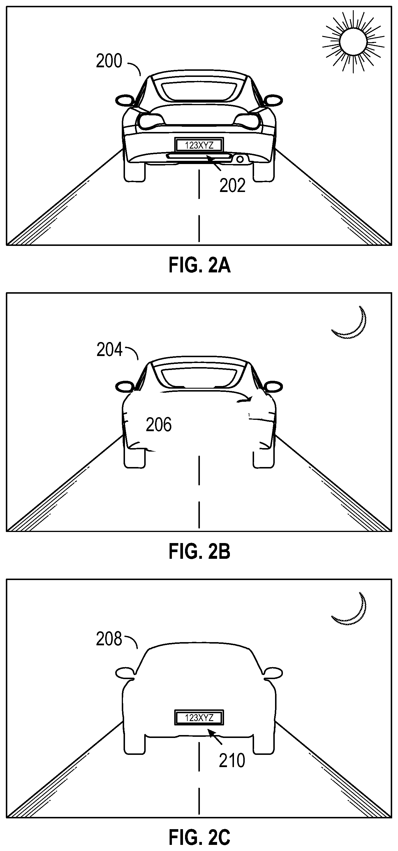
FIG. 2A is an illustration of an ideal clear image of a vehicle with legible markings thereon;
FIG. 2B is an illustration of a clear image of a vehicle with a license plate having illegible markings;
FIG. 2C is an illustration of an unclear image of a vehicle with a license plate having legible markings;
FIG. 3 is an illustration of a display of embodiments of the invention for presenting representative images of a license plate and soliciting user response;
FIG. 4 is a first flow diagram of steps that may be performed in embodiments of the invention;
FIGS. 5A, 5B, and 5C illustrate a second flow diagram of steps that may be performed in embodiments of the invention; and
The drawing figures do not limit the invention to the specific embodiments disclosed and described herein. The drawings are not necessarily to scale, emphasis instead being placed upon clearly illustrating the principles of the invention.
DETAILED DESCRIPTION
The following detailed description references the accompanying drawings that illustrate specific embodiments in which the invention can be practiced. The embodiments are intended to describe aspects of the invention in sufficient detail to enable those skilled in the art to practice the invention. Other embodiments can be utilized and changes can be made without departing from the scope of the invention. The following detailed description is, therefore, not to be taken in a limiting sense. The scope of the invention is defined only by the appended claims, along with the full scope of equivalents to which such claims are entitled.
In this description, references to "one embodiment," "an embodiment," or "embodiments" mean that the feature or features being referred to are included in at least one embodiment of the technology. Separate references to "one embodiment," "an embodiment," or "embodiments" in this description do not necessarily refer to the same embodiment and are also not mutually exclusive unless so stated and/or except as will be readily apparent to those skilled in the art from the description. For example, a feature, structure, act, etc. described in one embodiment may also be included in other embodiments, but is not necessarily included. Thus, the current technology can include a variety of combinations and/or integrations of the embodiments described herein.
Embodiments of the invention provide systems and methods of capturing video data that adjust recording attributes of one or more video cameras to scan for a legible image of a license plate or other identifying characters or markings on a vehicle. Further, embodiments of the invention determine whether or not a legible image has been captured, and may take additional steps based on the determination. The additional steps may include rescanning the scene or storing the image data.
Turning to the figures, and particularly FIG. 1A, a first embodiment of a recording system 10 is described. FIG. 1A includes an intermediate recording device manager 12 (or "manager 12"), a vehicle recording device 14 mounted in a police vehicle 16 (or other first responder's vehicle) and communicatively coupled (e.g., synced) to the recording device manager 12, and a personal recording device 18. Personal recording device 18 may be carried by a police officer 20 or other first responder and wirelessly synced to the recording device manager 12. The recording device manager 12 is operable to detect when the vehicle recording device 14, personal recording device 18, or any other synced device in range has started recording and to broadcast or transmit a signal to other synced recording devices in range, instructing recording by the respective device. The recording device manager 12 may also generate time stamps and unique serial numbers for a data recording, and create or collect metadata and transmit such time stamps, unique serial number, and metadata to the recording devices 14, 18 for corroborating the recorded data. For illustrative purposes, the recording system 10 includes the vehicle recording device 14 and the personal recording device 18, but it will be understood that duplicate or additional devices, such as audio recorders, thermal imagers, security cameras, radios, radar and LIDAR scanners, and electronic weapons, can be synced to the recording device manager 12. Specifically, multiple recording devices 14, 18 can be synced with the manager 12 simultaneously.
In embodiments of the invention, the vehicle recording device 14 and personal recording device 18 are each video cameras operable to record data, including without limitation, audio data and video data. Moreover, the recording devices 14, 18 are also operable to record or generate metadata associated with the recording, such that the data recorded by the devices 14, 18 includes the audio data, the video data, and/or the metadata associated with either or both of the audio and video data. Examples of metadata for an audio or video recording include a location (as determined by a GPS) where the data was recorded, a user who recorded the data or was otherwise associated with the recording device 14, 18 (e.g., an officer driving a police vehicle or an officer wearing the personal recording device 18), the time stamp and/or unique serial number, a trigger for the data recording event (e.g., what prompted a data capture scan by the recording devices), and other data related to the recorded event. Additionally, as further discussed below, the metadata may include or link to data derived from identifying marks on a subject vehicle.
The recording device manager 12 is illustrated in FIG. 1A as a standalone device but can be incorporated into other devices, such as a laptop (including external computing device 22), a radio, a recording device (including the vehicle recording device 14), a mobile communications device, a battery pack, or an electronic weapon. The recording device manager 12 may be permanently or removably mounted anywhere in the police vehicle 16, such as on the dashboard, center console, or windshield. Alternatively, the recording device manager 12 can be carried or worn by the police officer 20, such as on his utility belt or in his pocket.
Exemplary hardware included in embodiments of the invention is illustrated in FIG. 1B. Computer 102 can be a laptop computer, as illustrated as external computing device 22 of FIG. 1A. Depicted with computer 102 are several components, for illustrative purposes. In some embodiments, certain components may be arranged differently or absent. Additional components may also be present. Included in computer 102 is system bus 104, whereby other components of computer 102 can communicate with each other. In certain embodiments, there may be multiple busses or components may communicate with each other directly. Connected to system bus 104 is central processing unit (or "processor") 106. Also attached to system bus 104 are one or more random-access memory (RAM) modules. Also attached to system bus 104 is graphics card 110. In some embodiments, graphics card 104 may not be a physically separate card, but rather may be integrated into the motherboard or the processor 106. In some embodiments, graphics card 110 has a separate graphics-processing unit (GPU) 112, which can be used for graphics processing. Also on graphics card 110 is GPU memory 114. A display 116 may be connected (directly or indirectly) to graphics card 110 for user interaction. In some embodiments no display is present, while in others it is integrated into computer 102, or detached physically and remotely connected to computer 102. Similarly, peripherals such as keyboard 118 and mouse 120 may be connected to system bus 104. Like display 116, these or other peripherals may be integrated into computer 102, remotely connected, or absent. Also connected to system bus 104 is local storage 122, which may be any form of computer-readable media, and may be internally installed in computer 102 or externally and removeably attached.
Computer-readable media include both volatile and nonvolatile media, removable and nonremovable media, and contemplate media readable by a database. For example, computer-readable media include (but are not limited to) RAM, ROM, EEPROM, flash memory or other memory technology, CD-ROM, digital versatile discs (DVD), holographic media or other optical disc storage, magnetic cassettes, magnetic tape, magnetic disk storage, and other magnetic storage devices. These technologies can store data temporarily or permanently. However, unless explicitly specified otherwise, the term "computer-readable media" should not be construed to include physical, but transitory, forms of signal transmission such as radio broadcasts, electrical signals through a wire, or light pulses through a fiber-optic cable. Examples of stored information include computer-useable instructions, data structures, program modules, and other data representations.
Finally, network interface card (NIC) 124 is also attached to system bus 104 and allows computer 102 to communicate over a network. NIC 124 can be any form of network interface known in the art, such as Ethernet, ATM, fiber, Bluetooth, or Wi-Fi (i.e., the IEEE 802.11 family of standards). NIC 124 may connect computer 102 to a local network, optionally via a CAN bus 26, as further described below. The local network may in turn connected to Internet, or in some embodiments computer 102 may itself be directly connected to Internet.
Returning to FIG. 1A, external computing device 22 may be coupled to recording device manager 12 via wired or wireless connection. The external computing device 22 can be a laptop, tablet, mobile device, smartphone, or other computing device. The external computing device 22 displays a graphical user interface (GUI) by which the police officer 20 or other user may view recorded data and make selections regarding the recording system 10. As further described below, external computing device 22 may function as an input/output device to allow an officer to judge the legibility of characters captured in video data. External computing device 12 may include a central processing unit (CPU) and one or more random-access memory (RAM) modules, as well as a graphics card and display for user interaction. In some embodiments no display is present, while in others it may be spaced apart from and coupled to an external computing device 22. Similarly, peripherals such as keyboard and mouse may be coupled to external computing device 22. Like the display, these peripherals may be integrated into external computing device 22 or absent. External computing device 22 may be touch-sensitive, allowing an officer to input data or make selections via tap, swipe, or other gesture.
A power source 24 may be electronically connected to the vehicle recording device 14 through dedicated wiring. The power source 24 supplies power to each of the electronic components of the vehicle recording device and, in embodiments of the invention, to the recording device manager 12 and/or the personal recording device 18. In embodiments of the invention, the power source 24 is the police vehicle's battery but can be another power source, such as a battery cartridge of the external computing device 22.
The electronic connection between the recording device manager 12, the vehicle recording device 14, and the personal recording device 18 optionally includes a control area network (CAN) bus 26, which "directs traffic" for incoming and outgoing signals based on indicated importance or other factors and follows an algorithm for determining the order in which (or whether) signals are transmitted.
The vehicle recording device 14 is operable to record audio, video, and/or other data. In some embodiments, the vehicle recording device 14 is a video recording device such as one produced by Digital Ally, Inc., including the DVM100, DVM250, DVM250Plus, DVM250Law, DVM400, DV440Ultra, DVM470, DVM500, DVM500Plus, and DVM750. As described below, in some embodiments the vehicle recording device 14 is operable to receive a signal of a triggering event, while in other embodiments the vehicle recording device 14 utilizes the CAN bus 26 and is operable to receive time stamps and metadata in addition to the signal of a triggering event. The vehicle recording device 14 can be incorporated into the police vehicle's rear view mirror, dashboard, spotlight, or other locations associated with the police vehicle 16 or may be a stand-alone unit mounted within or on the police vehicle 16. The vehicle recording device 14 may receive power from the power source 24 through dedicated wiring. In addition to the exemplary vehicle recording devices listed above, a vehicle recording device is further described in commonly-owned U.S. Pat. No. 8,520,069, issued Aug. 27, 2013, entitled "Vehicle-Mounted Video System with Distributed Processing," the entirety of which is incorporated by reference herein.
The personal recording device 18 is small, portable, wearable, easily concealed, and is operable to record audio, video, thermal, chemical, or other data. The personal recording device 18 can be worn by the officer 20, such as on the officer's shirt, hat, eyeglasses or sunglasses, electronic weapon, breath analyzer, or other device accessed or used by the officer. The personal recording device 18 is operable to receive a signal instructing the device 18 to begin or stop scanning (as discussed in further detail below), a signal indicative of a triggering event, and time stamps and metadata corresponding to the recordings. Additionally, the personal recording device 18 may further include a clock for determining a time corresponding to when a particular item of data was recorded. An exemplary personal recording device is the "FIRSTVU HD" produced by Digital Ally, Inc. and further described in U.S. Pat. No. 9,019,431, issued Apr. 28, 2015, and commonly assigned with the present application, the entirety of which is hereby incorporated by reference into the present application.
Recordings generated by the recording devices 14, 18 and associated metadata may be temporarily or permanently stored in a local memory element (hereinafter "memory"), such as a memory of the particular recording devices 14, 18, and/or a memory of external computing device 22 located in the police vehicle 16. The recording devices 14, 18 may alternatively or additionally be allowed to upload recordings to an external server or storage device. The external server or storage device could be a large-capacity storage device 28, such as a DVR housed in the vehicle, or may be a centralized computing device, such as housed at a police precinct. These examples are not meant to be limiting; any form of data storage and duplication is intended within embodiments of the invention.
An exemplary scenario of the recording system 10 in use is now described for illustrative purposes. The recording system 10 may be used by the police officer 20 to record video data during an event such as a traffic stop. The recording device manager 12 may be mounted near the vehicle recording device 14, such as on the windshield of the police vehicle 16, or may be integrated within a housing of the vehicle recording device 14. Alternatively, the recording device manager 12 may be mounted anywhere within the police vehicle 16 that allows for the recording device manager 12 to communicate (either via a wired or wireless connection) with the vehicle recording device 14. In embodiments of the invention, the vehicle recording device 14 is oriented in a forward direction relative to a front of the vehicle to record the traffic stop, and in yet further embodiments, multiple vehicle recording devices 14 may be mounted in or on the vehicle and oriented in different directions relative to the vehicle, such as backwards towards a rear of the vehicle, and to the left and right sides of the vehicle. The personal recording device 18 is mounted to the police officer's person or is otherwise carried by the police officer 20, such as on a lanyard, belt, or shoulder. In embodiments of the invention, the personal recording device 18 may include a GPS, an RFID, or another type of location or identification feature or sensor (not shown) that informs the recording device manager 12 of the relational location of the personal recording device 18 to the recording device manager 12. Alternatively, the officer may carry on their person a GPS (such as housed within or associated with a mobile communications device), RFID, or other type of location or identification sensor. Recording system 10 may include additional sensors not illustrated in FIG. 1A, such as a rangefinder. Data collected from such sensors may be stored along with video, audio, and metadata, and may be used in detection of trigger parameters or determination of scan range limits, as further discussed below.
Embodiments of the invention are not intended to be limited to the traffic stop situation described above. Embodiments may be stationary or mobile camera systems employed by businesses to record the identity of vehicles arriving and departing from a parking lot. Alternatively, embodiments may be employed in maritime settings, such as for tracking of shipping containers. In other embodiments of the invention, a military installation may use a camera system to pre-screen vehicles approaching a secure location. Any system including one or more video recording devices that scan for a legible image of a marking on a vehicle may fall within embodiments of the invention.
Returning to the law enforcement example, in embodiments of the invention, the recording device manager 12 may activate a data capture scan (or simply "scan") from vehicle recording device 14 and/or personal recording device 18 responsive to a triggering event (also more simply known as a "trigger"). Examples of a triggering event may include, for example, turning on the vehicle's siren and/or signal lights, an indication that the vehicle is parked, an electronic detection of a subject car or a license plate, an accelerometer measurement outside a pre-established norm, a position of the vehicle and/or officer as measured by a GPS, a vehicle crash event, the police vehicle 16 attaining a threshold speed (e.g., 80 m.p.h.), activation of an electronic weapon, opening of the vehicle door, and/or activation of a radar or the radar detecting a subject car's speed at or over a pre-determined speed. In embodiments, the recording device manager 12 may receive a signal from, for example, the vehicle recording device 14, external computing device 22, or police vehicle 16 indicative of a triggering event. In response to receipt of the signal, or based on a type of triggering event as evidenced by the signal, the recording device manager 12 may instruct recording by the vehicle recording device 14 or the personal recording device 18 to begin a scan. As an exemplary scenario, the recording device manager 12 may receive a signal identifying a triggering event of a police vehicle 16 being placed in park while the vehicle signal lights are activated. Upon receipt of the signal, the recording device manager 12 sends a signal to either or both of the vehicle recording device 14 or the personal recording device 18 to instruct the devices 14, 18 to begin a scan. It should be appreciated that other types of triggering events and exemplary scenarios can be employed.
Alternatively, a data capture scan may be activated manually based on a user's manual selection, for instance via a police officer's button press of recording device manager 12, vehicle recording device 14, or external computing device 22. A manual selection may be made remotely from a fob carried by police officer 20 or a control integrated into the structure of personal recording device 18. In embodiments of the invention, a manual selection may be made by a remote user, such as by a dispatcher at a police station. As further discussed below, whether initiated via a trigger or via manual indication, a scan serves to adjust one or more recording attributes between a lower limit and upper limit to search for a legible image of a license plate or other vehicle marking.
FIGS. 2A-C illustrate examples of images captured by a recording device such as vehicle recoding device 14 of a subject vehicle 200,204,208 with a license plate 202,210 during a typical traffic stop situation introduced above. FIG. 2A illustrates a captured image of a subject vehicle 200 during a traffic stop occurring on a clear day with ideal recording conditions. Factors such as the make, model, color, damage, decals, bumper stickers, etc. of vehicle 200 can be distinguished in the captured video data, as well as the actions of figures in the scene. In particular, the license plate 202 of vehicle 200 is legible. Under such conditions, the license plate 202 will likely be clearly readable from portions of the video data captured (which may be motion video and/or still frames) by a human observer and/or a computer character recognition program.
FIG. 2B illustrates a similar situation to that illustrated in FIG. 2A, only in this instance the traffic stop is occurring at night, when recording conditions are less ideal. A subject vehicle 204 identical to vehicle 200 in FIG. 2A has been pulled over, and an image is captured from vehicle recording device 14 mounted forward-facing in police vehicle 16. The subject vehicle 204 can again be distinguished by factors such as make, model, color, etc., though perhaps to a lesser extent than in FIG. 2A. However, interference from sources such as the headlights of police vehicle 16 reflecting from the rear 206 of subject vehicle 204 has washed out the image of the license plate, making it completely illegible. This effect is known as "bloom," and inhibits the ability of a user or computer program to definitively determine the identity of subject vehicle 204 from the recorded video data. As seen in FIG. 2B, the effect of bloom can be impactful enough to saturate the recording camera in region 206 of the image, such that the license plate cannot be seen at all.
FIG. 2C illustrates the traffic stop situation a third time, again occurring at night as in FIG. 2B. A subject vehicle 208 identical to vehicles 200,204 in FIGS. 2A-B has been pulled over, and an image is captured from vehicle recording device 14 mounted forward-facing in police vehicle 16. In illustrated image capture of FIG. 2C, one or more recording attributes of vehicle recording device 14 have been adjusted such that the bloom effect of the reflected headlights has been minimized. The subject vehicle 208 as a whole is actually much less distinguishable in terms of make, model, color, etc. compared to subject vehicle 204 of FIG. 2B, but the critical information of license plate 210 is legibly captured. The video data recording illustrated in FIG. 2C may be less likely to capture any events happening in the recorded scene but is valuable for establishing proof of the identity of subject vehicle 208.
Embodiments of the invention adjust one or more recording attributes of one or more video recording devices, such as vehicle recording device 14 or personal recording device 18, to scan for at least one frame of a legible image of markings on a vehicle, such as those on a license plate. As in the example illustrated in FIG. 2C, the frame containing legible markings for which the recording devices are scanning may be dark, obscured, unfocused, or otherwise unclear with respect to any elements of the scene other than the license plate (or other vehicle markings of interest). This is not intended to be limiting, as the legible frame may present a clear view of all elements of the scene, as in FIG. 2A. Examples of recording attributes that may be adjusted include gain, shutter speed, focus, white balance, sharpness, backlight compensation, iris aperture, or any other applicable adjustable attribute of the recording devices.
Because adjusting the recording attribute(s) of the recording devices 14, 18 to legibly capture the license plate 200,210 may reduce visibility of other elements in the recorded scene, embodiments of the invention may not permanently set the recording attributes to such values. Doing so is unnecessary, as only a single legible frame is needed for identification purposes. Additionally, permanent adjustment of the recording attributes might require significant computation to determine the appropriate values and may render the recording less valuable as a documentation of events in the scene. Rather, in embodiments of the invention, selected recording attributes are only temporarily adjusted to scan for a legible image of a marking on a vehicle, such as a license plate. For example, a recording attribute such as gain may be adjusted across a range of values, searching for a single value within that range at which the license plate is legible. In embodiments of the invention, one or more recording devices 14, 18 perform a scan for legible markings on a vehicle while other recording devices 14, 18 continue recording video data using normal recording attributes. In this way the portion of recorded video occurring during the scan is recorded as usual. It should also be appreciated that embodiments of the invention may employ a dedicated vehicle recording device 14 for capturing the image or scanning the vehicle for markings.
The scan range for a particular attribute includes a lower limit and an upper limit, each of which may be a predetermined limit programmed into memory, may be selected manually by a user, or may be dynamically selected by the recording system 10 based on factors such as the time of day, a sensed ambient light level, or a distance measurement. Such a distance measurement may be, for instance, from the recording device 14, 18 to the subject vehicle 200. Alternatively, a distance measurement may be estimated by an officer 20 and entered via external computing device 22. Manual selections may be presented to the user as multiple choice selections based on the user's evaluation of the visibility of the scene, such as a "low-light" scan range, "high interference" scan range, or "long distance" scan range. These scan ranges are meant only as examples, and are not intended to be limiting in any way.
A recording attribute may be adjusted within a scan range by a continuous "sweep" of the scan range or may be adjusted incrementally by set values. The incremental values by which a recording attribute is adjusted may be uniform increments, which may be predetermined increments programmed into memory or may be selected manually by a user. Alternatively, uniform increments may be dynamically selected by the recording system based on sensed parameters such as the time of day, a sensed ambient light level, or a distance measurement. Like the scan range limits, the increments of adjustment of a recording attribute within a scan range may be presented to the user as multiple choice selections based on their evaluation of the visibility of the scene, such as "low-light" adjustments, "high interference" adjustments, or "long distance" adjustments. Again, these are meant only as examples, and are not intended to be limiting in any way.
In the course of performing a scan for a legible marking on a vehicle, embodiments of the invention may adjust more than one recording attribute within respective scan ranges, each scan range including a respective upper and lower limit. For example, a scan may adjust gain between a minimum level of 30% and a maximum level of 70% and also adjust shutter speed between 0.02 and 0.05 seconds. The adjustments may be done simultaneously, or may be performed independently of one another, with the value of one recording attribute adjusted while the other is held at a static value. Specifically, a first recording attribute may remain at a first value within its first scan range while a second recording attribute is adjusted within its second scan range, and the second recording attribute may remain at a second value within its second scan range while the first recording attribute is adjusted within its first scan range.
In some embodiments, the value of a given recording attribute may be adjusted throughout a scan range multiple times, with the values of other recording attributes held at different static values each time. For instance, gain may be adjusted between a 30% lower limit and a 70% upper limit while the shutter speed is held at 0.025 seconds, and then adjusted again between the same limits while the shutter speed is held at 0.05 seconds. The shutter speed may then be adjusted one or more times while the gain is held at one or more static values. Static values may be predetermined, selected by a user, or determined dynamically by the system upon initiation of a scan. The above examples are not intended to be limiting. In embodiments of the invention, more than two recording attributes may be adjusted simultaneously or independently while other recording attributes are held static. Specifically, a scan may include a third scan range including a third upper limit and a third lower limit. For example, a single scan may adjust shutter speed, gain, and white balance between upper and lower limits. Any combination of increments, selected type and number of recording attributes, upper and lower limits, and independence or simultaneity of adjustments are intended within embodiments of the invention.
In embodiments of the invention, representative image captures from a scan may be presented to a user on a display, as illustrated in FIG. 3. As discussed below, a user may respond to one or more images presented on the display via touch or through a separate input device to indicate success or failure of the scan and/or select further steps to be performed. FIG. 3 is intended only as an illustration of a display presented in embodiments of the invention, and is not intended to be limiting.
FIG. 4 broadly illustrates steps performed in operation of an embodiment of the invention. These steps may be performed during an event such as a traffic stop, where a video recording of a subject vehicle 200,204,208 needs to capture a legible image of a license plate 202,210. Prior to step 402, one or more recording devices 14, 18 may or may not already be active, recording, and/or storing video data. At step 402, an indication to begin a scan is provided to the system. As discussed above, this indication to begin may be provided by a user's manual input or based on one or more sensed trigger parameters. In some embodiments, the indication to begin a scan may activate one or more recording devices 14, 18 and/or cause them to temporarily or permanently store video data. In response to the received indication, a scan is initiated by the system based on a program stored in memory, user input, and/or sensed parameters. At step 404, a first recording attribute, such as gain, is adjusted between within a first scan range. The first scan range is bound by an upper limit and a lower limit, which may be predetermined, based on sensed parameters, or manually selected by a user. While the first recording attribute is being adjusted, all other recording attributes may be held at selected values. The selected static values for each recording attribute not being adjusted may be predetermined, based on sensed parameters, or manually selected by a user. At step 406, the first recording attribute is held at a static value while a second recording attribute, such as shutter speed, is adjusted within a second scan range. Again, while the second recording attribute is being adjusted, all other recording attributes may be held at selected values, which again may be predetermined, based on sensed parameters, or manually selected by a user. In embodiments of the invention, these steps may be preformed for three or more recording attributes within their respective scan ranges. Further, the adjustment of each recording attribute within their respective scan ranges may alternatively be performed simultaneously, to achieve a faster (though possibly less robust) scan.
At step 408, a determination is made as to whether or not markings on a vehicle, such as those appearing on a license plate, have been legibly captured. In embodiments of the invention, representative frames from a scan may be presented via a display (such as on external computing device 22) for confirmation and/or selection by a user. As seen in FIG. 3, in embodiments of the invention a display screen 300 is presented to a user with frames 304, 306, and 308 selected from a scan. Frame 304 has the clearest image of the vehicle, but has no legible license plate data as explained in relation to FIG. 2B. Frames 306 and 308 have dark, blurry, or otherwise obscured images of the vehicle, but have successfully captured the license plate data needed for identification. A user may respond to these displayed frames 304,306,308 via touching the screen or use of a separate input device to select one or more that include legible data. For instance, an officer 20 may select frames 306 and 308, indicating that the license plate 123XYZ is legible in each of these frames. Next, the officer may tap button 310 in response window 302 to store the selected frames in memory, associated with the video data captured of the traffic stop event. A text recognition program may then extract the data from one or more of the selected frames. At this point, the system proceeds to step 410 in which data from the license plate may be saved, possibly as metadata relating to the captured video data. For instance, the title of the stored video may be appended with the recognized license plate data. Additionally or alternatively, metadata related to the captured video data may include a link to a still image of the license plate data stored in memory.
FIG. 3 further includes buttons 312 and 314 in response window 302, as well as timer 316. Button 312 may be pressed by an officer 20 to indicate that a scan should be cancelled. This may be of use, for example, in case a traffic stop is uneventful or another officer has already documented the scene. Selection of button 312 may allow a user to rescan the scene if none of the frames 304,306,308 have legibly captured the license plate data. Selection of Rescan button 312 may initiate a modified scan, as further described below. Finally, FIG. 3 displays a timer 316, indicating a remaining amount of time before a timeout occurs. The total amount of time allowed before timeout may be programmed into memory or set by the user. Upon expiration of timer 316, the system may automatically cancel the scan, rescan, or initiate a modified scan. Alternatively, upon timeout the system may proceed to step 410, storing all of the displayed frames 304,306,308 in memory.
In other embodiments, step 408 may be performed initially by a computer text recognition algorithm. The algorithm may select representative frames from the scan and extract text from each frame, searching for a string of text that fits the appropriate format of a license plate. Alternatively, the algorithm may run continuously during the scan, and may halt the scan upon recognition of a string of characters in a valid format, such as in a license plate format. Valid formats may be stored in memory. In embodiments of the invention, the computer-recognized screen may be presented to a user along with an image frame from which it was extracted for user confirmation of successful license plate capture. At this point, the system proceeds to step 410 in which data from the license plate may be saved, possibly as metadata relating to the captured video data.
As has been described above, computer and/or user determination of successful capture of a legible image of a marking on a vehicle may initiate storage of at least a portion of the scan that includes the legible marking. However, in the event that capture of a legible image is determined to be unsuccessful, the system may perform an additional scan. The additional scan may activate automatically or in response to selection by a user. The additional scan may use recording attributes, scan ranges, and adjustment increments that are identical to those of the prior scan(s). Alternatively, the additional scan may be a modified scan, differing from the prior scan(s) in any or all of these elements.
A modified scan may be beneficial in situations with particularly difficult viewing conditions to provide an increased likelihood of capturing a legible image of a marking on a vehicle. The modified scan may simply select one or more different recording attributes for adjustment, such as gain and frame rate rather than white balance and focal distance. The modified scan may adjust the same recording attributes, but choose different upper and/or lower limits, modifying the scan range of one or more of the recording attributes. Modified upper and lower limits may define a larger scan range in a modified scan for a particular recording attribute, and/or may shift the original scan range. A modified scan may alternatively or additionally change the simultaneity of adjustment of recording attributes. For example, if in a previous failed scan, gain and white balance were adjusted within their respective scan ranges simultaneously, in a subsequent modified scan gain may be held at a static value while white balance is adjusted and vice versa. Any or all of the modifications discussed may be employed in a given modified scan, as well as any other modifications not expressly described.
While reference has been made above to the various components and techniques of embodiments of the invention, the description that follows will provide further examples systems and processes that may be added in embodiments of the invention. The description below is intended to merely exemplify steps that may be taken in practice of operation of embodiments of the invention and is not intended to be limiting. Further steps that may be performed in practice of some embodiments of the invention are illustrated in FIGS. 5A-C and herein described.
FIG. 5A begins at step 502, corresponding to step 402 of FIG. 4, in which an indication to begin a scan is provided to the system by a human or computer. The indication may be in response to one or more trigger parameters such as an indication that a police vehicle 16 is parked, a computer detection of a subject car, a detection of a license plate 200, an activation of a vehicle siren, and an activation of signal lights. At step 504, the lower and upper limits of the first scan range are determined for a first recording attribute. These limits may be predetermined, selected by a user, or determined dynamically based on sensed parameters such as a sensed light level. At step 506 the system determines whether or not the first recording attribute will be adjusted by uniform increments. If the increments are uniform, the process proceeds to step 508, at which the system determines whether the size of the uniform increments has been predetermined and stored in memory, or if the size needs to be determined based at least partially on sensed factors. If they are predetermined, the system proceeds to step 510, adjusting the first recording attribute between the first upper and lower limits using the uniform increments. If sensed factors must be taken into account, the system does so at step 512 before proceeding to the adjustment at step 510.
Returning to step 506, if the increments of adjustment are not uniform, the process proceeds to step 514, at which the system determines whether or not the system should perform a continuous sweep through across the scan range. If this determination is yes, the system adjusts the first recording attribute in this way at step 516. If the determination at step 514 is no, the system adjusts the first recording attribute using a set of predetermined or random non-uniform increments at step 518.
Each of these regimes of adjustment of the first recording attribute converge at step 520, at which the preceding process (beginning at step 504) is performed once again, this time with respect to the second recording attribute. In step 520, as in step 504, the system determines the upper and lower limits for the second scan range, corresponding to the second recording attribute. Again in steps 522, 524, 528 and 530 (FIG. 5B), determinations are made about how the second recording attribute is to be scanned within the second scan range. Each of these determinations are made in the same manner as the decision points at steps 506, 508, and 514, resulting in adjustment of the second recording attribute at steps 526, 528, or 534. The determinations made for adjustment of the second recording attribute may or may not be the same as those made for the first recording attribute. For example, the first recording attribute may be gain, adjusted by 1% increments from 50% to 100%, while the second recording attribute, may be white balance, adjusted continuously from the minimum to maximum white balance available to the system. This is meant only as an example, and is not intended to be limiting. Any combination of recording attributes, scan ranges, and scan regimes is intended to be within embodiments of the invention.
Specifically, at step 520, the lower and upper limits of the second scan range are determined for a second recording attribute. These limits may be predetermined, selected by a user, or determined dynamically based on sensed parameters such as a sensed light level. At step 522 the system determines whether or not the second recording attribute will be adjusted by uniform increments. If the increments are uniform, the process proceeds to step 524, at which the system determines whether the size of the uniform increments has been predetermined and stored in memory, or if the size needs to be determined based at least partially on sensed factors. If they are predetermined, the system proceeds to step 526, adjusting the second recording attribute between second first upper and lower limits using the uniform increments. If sensed factors must be taken into account, the system does so at step 528 before proceeding to the adjustment at step 526.
Returning to step 522, if the increments of adjustment are not uniform, the process proceeds to step 530, at which the system determines whether or not the system should perform a continuous sweep through across the second scan range. If this determination is yes, the system adjusts the second recording attribute in this way at step 532. If the determination at step 530 is no, the system adjusts the second recording attribute using a set of predetermined or random non-uniform increments at step 534.
Regardless of the determinations made, all of these regimes of adjustment of the second recording attribute converge at step 536. At this step the system determines whether or not a third attribute is to be adjusted within a third scan range. If so, the process proceeds through steps 538, 540, 542, 544, 546, 548, and 550 for determining the method of adjusting the third recording attribute. These steps are performed in the same manner as previously performed for the first and second recording attributes. These steps may be repeated for an arbitrary number of recording attributes, as determined by the system and/or a user.
Specifically, at step 540, the lower and upper limits of the third scan range are determined for a third recording attribute. These limits may be predetermined, selected by a user, or determined dynamically based on sensed parameters such as a sensed light level. At step 542 the system determines whether or not the third recording attribute will be adjusted by uniform increments. If the increments are uniform, the process proceeds to step 544, at which the system determines whether the size of the uniform increments has been predetermined and stored in memory, or if the size needs to be determined based at least partially on sensed factors. If they are predetermined, the system proceeds to step 546, adjusting the third recording attribute between the third upper and lower limits using the uniform increments. If sensed factors must be taken into account, the system does so at step 548 before proceeding to the adjustment at step 546.
Returning to step 542, if the increments of adjustment are not uniform, the process proceeds to step 550, at which the system determines whether or not the system should perform a continuous sweep through across the third scan range. If this determination is yes, the system adjusts the first recording attribute in this way at step 552. If the determination at step 550 is no, the system adjusts the third recording attribute using a set of predetermined or random non-uniform increments at step 554.
When the final recording attribute has been adjusted (which in the case of FIG. 5C is the third recording attribute) the system proceeds to step 554, where a determination is made of the legibility of the captured by the scan. This may be determined by a user in step 556. For example, the system may display one or more captured images of markings to a user for confirmation of success. Alternatively, computer text-recognition software may independently determine the success or failure of the scan. Via either approach, if in step 558 the system determines a successful capture of a legible image of markings on a vehicle, a portion of the scan including the markings is stored in memory at step 560. If, however, in step 558 the system determines an unsuccessful capture of a legible image of markings on a vehicle, the system proceeds to step 562 to determine whether an additional scan should be performed. This step may be performed automatically by the system or in response to user input. Determination of initiation of an additional scan by a user may be subject to a timeout, as described above. If an additional scan is rejected at step 562, the system quits at step 564, returning to its initial condition of waiting for an indication to begin a scan. If an additional scan is initiated at step 562, the system returns to step 502 to repeat the entire process. The additional scan may be identical to the first or may be a modified scan, differing in number or type of recording attributes adjusted, methods of adjustment, and/or scan ranges as described above.
It should be appreciated that, while the above disclosure is directed mainly to the field of law enforcement, some embodiments of the invention may be employed for any pursuit requiring legible video capture of information. Embodiments of the invention may be used in any setting or field, such as military or road maintenance vehicles, to maximize the likelihood of capturing a legible image of readable characters using a video camera. In embodiments of the invention, readable characters may be identified from sources other than license plates, such as billboards, street signs, bumper stickers, or apparel. Further, though the description above is uses a car as subject vehicle 200,204,208, embodiments of the invention could equivalently be employed to identify a subject boat, trailer, motorcycle, etc. Embodiments of the invention may be used by private individuals or businesses to help prevent fraud, identify visitors, or track shipments. The law enforcement field discussed is merely exemplary and should not be construed as limiting.
* * * * *
References
-
laipac.com/multimedia-rear-mirror.htm
-
techdadreview.com/2013/06/19atc-chameleon
-
en.wikipedia.org/wiki/Breathalyzer
-
policeone.com/police-products/body-cameras/articles/527231-0-TASER-Axon-Flex-The-next-generation-of-body-camera
-
electronics.howstuffworks.com/gadgets/automotive/breathalyzer1.htm
-
kopin.com
-
case-mod.com/lilliput-rv1850np-rear-view-mirror-tft-lcd-screen-with-camera-p-1271.html
-
oregonscientificstore.com/Oregon-Scientific-ATC-Chameleon-Dual-Lens-HD-Action-Camera.data
-
wassom.com/digital-eyewear-for-law-enforcement.html
-
opticsplanet.com/digital-ally-first-vu-mountable-digital-camera-video-recorder.html?gclid=CIKohcX05rkCFSIo7AodU0IA0g&ef_id=UjCGEAAAAWGEjrQF:20130925155534:s
-
driftinnovation.com/support/firmware-update/x170
-
dynaspy.com/hidden-cameras/spy-cameras/body-worn-wearable-spy-cameras
-
fireeye.en.ecplaza.net/law-enforcement-dvr--238185-1619696.html
-
edesix.com/edesix-products
-
gopro.com/products/?gclid=CKqHv9jT4rkCFWZk7AodyiAAaQ
-
isawcam.co.kr
-
kustomsignals.com/index.php/mvideo/vievu
-
leacorp.com/products/SCORPION-Micro-Recorder-Patrol-kit.html
-
looxcie.com/overview?gclid=CPbDyv6piq8CFWeFQAodlhXC-w
-
midlandradio.com/Company/xtc100-signup
-
panasonic.com/business/provideo/ag-hmr10.asp
-
pointofviewcameras.com/military-police
-
vio-pov.com/index.php
-
siv.co.kr
-
spytechs.com/spy_cameras/mini-spy-camera.htm
-
stalkerradar.com/law_vue.shtml
-
elmo.co.jp/suv-cam/en/product/index.html
-
taser.com/products/on-officer-video/axon-body-on-officer-video
-
-
-
tideleader.en.gongchang.com/product/14899076
-
ucorder.com
-
veho-uk.fastnet.co.uk/main/shop.aspx?category=CAMMUVIHD
-
-
vidmic.com
-
vievu.com/vievu-products/vievu-squared
-
watchguardvideo.com/copvu/overview
-
secgru.com/DVR-Witness-Cam-Headset-Video-Recorder-SG-DVR-1-COP.html
-
wolfcomusa.com/Products/Products.html
-
asianwolf.com/covert-bodycam-hq-angeleye.html
-
brickhousesecurity.com/body-worn-covert-spy-cameras.html?sf=0#sortblock&CMPID=PD_Google_%22body+camera%22&utm_source=google&utm_medium=cpc&utm_term=%22body+camera%22&mm_campaign=876a94ea5dd198a8c5dc3d1e67eccb34&keyword=%22body+camera
-
amazon.com/s/ref=nb_sb_ss_i_0_4?url=search-alias%3Dphoto&field-keywords=wearable+camcorder&x=0&y=0&sprefix=wear
- /k-h-b.com/board/board.php?board=products01&comand=body&no=1
-
k-h-b.com/sub1_02.html
-
giantfreakinrobot.com/sci/coming-3d-projectors-transmit-holograms-cell-phone.html
-
revealmedia.com/buy-t166/cameras/rs3-sx.aspx
-
D00000
D00001
D00002
D00003
D00004
D00005
D00006
D00007
D00008
XML
uspto.report is an independent third-party trademark research tool that is not affiliated, endorsed, or sponsored by the United States Patent and Trademark Office (USPTO) or any other governmental organization. The information provided by uspto.report is based on publicly available data at the time of writing and is intended for informational purposes only.
While we strive to provide accurate and up-to-date information, we do not guarantee the accuracy, completeness, reliability, or suitability of the information displayed on this site. The use of this site is at your own risk. Any reliance you place on such information is therefore strictly at your own risk.
All official trademark data, including owner information, should be verified by visiting the official USPTO website at www.uspto.gov. This site is not intended to replace professional legal advice and should not be used as a substitute for consulting with a legal professional who is knowledgeable about trademark law.