Nickel-based alloys
Wright , et al. Dec
U.S. patent number 10,519,529 [Application Number 14/548,488] was granted by the patent office on 2019-12-31 for nickel-based alloys. This patent grant is currently assigned to QUESTEK INNOVATIONS LLC. The grantee listed for this patent is QuesTek Innovations LLC. Invention is credited to Dana J. Frankel, Jiadong Gong, Weiming Huang, Jeremy Hoishun Li, Abhijeet Misra, James A. Wright.


| United States Patent | 10,519,529 |
| Wright , et al. | December 31, 2019 |
Nickel-based alloys
Abstract
An alloy includes, in weight percentage, about 20.0% to about 25.0% chromium, 0% to about 5.0% molybdenum, about 3.0% to about 15.0% cobalt, about 1.5% to about 6.0% niobium, about 1.0% to about 3.0% tantalum, about 1.0% to about 5.0% tungsten, 0% to about 1.0% aluminum, 0% to about 0.05% carbon, 0% to about 0.01% titanium, and the balance nickel and incidental elements and impurities, wherein the alloy includes L1.sub.2 and D0.sub.22 precipitates in a compact morphology.
| Inventors: | Wright; James A. (Los Gatos, CA), Huang; Weiming (State College, PA), Misra; Abhijeet (Mountain View, CA), Li; Jeremy Hoishun (Sunnyvale, CA), Gong; Jiadong (Evanston, IL), Frankel; Dana J. (Chicago, IL) | ||||||||||
|---|---|---|---|---|---|---|---|---|---|---|---|
| Applicant: |
|
||||||||||
| Assignee: | QUESTEK INNOVATIONS LLC
(Evanston, IL) |
||||||||||
| Family ID: | 56552877 | ||||||||||
| Appl. No.: | 14/548,488 | ||||||||||
| Filed: | November 20, 2014 |
Prior Publication Data
| Document Identifier | Publication Date | |
|---|---|---|
| US 20160222490 A1 | Aug 4, 2016 | |
Related U.S. Patent Documents
| Application Number | Filing Date | Patent Number | Issue Date | ||
|---|---|---|---|---|---|
| 61906512 | Nov 20, 2013 | ||||
| Current U.S. Class: | 1/1 |
| Current CPC Class: | F28F 21/087 (20130101); C22C 19/055 (20130101); C22C 1/023 (20130101); C22F 1/10 (20130101) |
| Current International Class: | C22F 1/10 (20060101); C22C 19/05 (20060101); C22C 1/02 (20060101); F28F 21/08 (20060101) |
| Field of Search: | ;420/442 |
References Cited [Referenced By]
U.S. Patent Documents
| 4108648 | August 1978 | Zhurkina et al. |
| 4749546 | June 1988 | Burley |
| 5010316 | April 1991 | Burley |
| 5372662 | December 1994 | Ganesan |
| 5529642 | June 1996 | Sugahara et al. |
| 5879818 | March 1999 | Kinomura et al. |
| 5882586 | March 1999 | Tamura et al. |
| 5972289 | October 1999 | Sikka et al. |
| 6004408 | December 1999 | Montagnon |
| 6605164 | August 2003 | Kennedy et al. |
| 8226886 | July 2012 | Hanlon et al. |
| 2007/0227630 | October 2007 | Augustins Lecallier et al. |
| 2010/0080729 | April 2010 | Biondo et al. |
| 2010/0272597 | October 2010 | Qiao et al. |
| 2010/0279148 | November 2010 | Hu |
Other References
|
Campbell, "Manufacturing Technology for Aerospace Structural Materials," 2006, p. 260-263. cited by applicant. |
Primary Examiner: Yang; Jie
Attorney, Agent or Firm: Michael Best & Friedrich LLP
Government Interests
FEDERALLY-SPONSORED RESEARCH AND DEVELOPMENT
Activities relating to the development of the subject matter of this invention were funded at least in part by the U.S. Government, NSF Award Number 0839678 and Department of the Air Force Contract Number FA8650-09-D-2921, and thus the U.S. may have certain rights in the invention.
Parent Case Text
CROSS-REFERENCE TO RELATED APPLICATIONS
This application claims priority to U.S. Provisional Application 61/906,512, filed Nov. 20, 2013, and is herein incorporated by reference in its entirety.
Claims
The invention claimed is:
1. An alloy comprising, in weight percentage, about 20.0% to about 25.0% chromium, 0% to 4% molybdenum, about 3.0% to about 15.0% cobalt, about 1.5% to about 6.0% niobium, about 1.0% to about 3.0% tantalum, about 1.0% to about 5.0% tungsten, 0% to about 1.0% aluminum, 0% to about 0.05% carbon, 0% to about 0.01% titanium, and the balance nickel and incidental elements and impurities, wherein the alloy includes L1.sub.2 and D0.sub.22 precipitates in a compact morphology; wherein the ratio of the D0.sub.22 phase fraction to the L1.sub.2 phase fraction is about 3:1 to about 5:1, at about 760.degree. C.; and wherein the alloy has a Vickers Hardness Number of at least 360.
2. The alloy of claim 1, wherein the alloy comprises, in weight percentage, 0% to about 3.0% molybdenum, about 5.0% to about 10.0% cobalt, about 3.0% to about 4.0% niobium, about 1.0% to about 2.0% tantalum, about 1.0% to about 3.0% tungsten, about 0.02% to about 0.05% carbon, and the balance nickel and incidental elements and impurities.
3. The alloy of claim 1, wherein the combination of aluminum and titanium in the alloy is, by weight, about 0.1% to about 1.0%.
4. The alloy of claim 1, wherein titanium is not included in the alloy.
5. The alloy of claim 1, wherein the surface tension between the L1.sub.2 phase and the FCC matrix is greater than the surface tension between the L1.sub.2 phase and D0.sub.22 phase.
6. The alloy of claim 1, wherein the alloy substantially avoids the .sigma.- and .eta.-phase at 760.degree. C.
7. The alloy of claim 1, wherein the alloy has a Vickers Hardness Number of at least 360 after aging at 760.degree. C. for 24 hours; wherein the alloy has a Vickers Hardness Number of at least 370 after aging at 760.degree. C. for 48 hours; and wherein alloy has a Vickers Hardness Number of at least 380 after aging at 760.degree. C. for 96 hours.
8. The alloy of claim 1, wherein the L1.sub.2 solvus temperature is less than or equal to 900.degree. C.
9. The alloy of claim 1, wherein the D0.sub.22 solvus temperature is less than or equal to 1000.degree. C.
10. The alloy of claim 1, wherein the Scheil solidification temperature range is less than 110.degree. C.
11. The alloy of claim 1, wherein the Scheil solidification temperature range is less than 100.degree. C.
12. The alloy of claim 1, wherein the alloy comprises, in weight percentage, about 21.0% chromium, about 3.0% molybdenum, about 7.0% cobalt, about 4.0% niobium, about 2.0% tantalum, about 1.0% tungsten, about 1.0% aluminum, about 0.03% carbon, and the balance nickel and incidental elements and impurities.
13. The alloy of claim 1, wherein the alloy comprises, in weight percentage, about 25.0% chromium, about 7.0% cobalt, about 3.5% niobium, about 1.0% tantalum, about 2.5% tungsten, about 1.0% aluminum, about 0.03% carbon, and the balance nickel and incidental elements and impurities.
14. A manufactured article comprising the alloy of claim 1.
15. The article of claim 14, wherein the article is a fin for a heat exchanger.
16. The alloy of claim 1, wherein the alloy comprises, in weight percentage, 0% to about 3.0% molybdenum, the balance nickel and incidental elements and impurities.
17. An alloy comprising, in weight percentage, about 20.0% to about 25.0% chromium, 0% to about 5.0% molybdenum, about 3.0% to about 15.0% cobalt, about 1.5% to about 6.0% niobium, about 1.0% to about 3.0% tantalum, about 1.0% to about 5.0% tungsten, 0% to about 1.0% aluminum, 0% to about 0.05% carbon, 0% to about 0.01% titanium, and the balance nickel and incidental elements and impurities, wherein the alloy includes L1.sub.2 and D0.sub.22 precipitates in a compact morphology; wherein the sum of the L1.sub.2 phase fraction and the D0.sub.22 phase fraction is about 0.1 to about 0.14; and wherein the ratio of the D0.sub.22 phase fraction to the L1.sub.2 phase fraction is about 3:1 to about 5:1, at about 760.degree. C.
18. The alloy of claim 17, wherein the L1.sub.2 phase and the D0.sub.22 phase are stable equilibrium phases at about 760.degree. C.
Description
BACKGROUND
Aircraft with a turbine engine compressor output hot air. Heat exchangers can bleed this hot air over stacks of fins and thereby control the environmental temperature in aircrafts and also increase efficiency of the engine. Each fin measures generally below 0.3 mm in thickness and is shaped to maximize the surface-to-volume ratio. The fins are typically brazed on a base metal at a temperature above about 1040.degree. C., after which the fin stacks are welded to the aircraft. Since the fins undergo thermal cycles during operation, they are expected to show adequate resistance to thermal fatigue. One way to increase the resistance to thermal fatigue is to employ thicker fins. However, thicker fins may add undesirable weight to the aircraft and decrease the thermal conductance.
Current materials for heat exchangers can withstand only a limited range of temperature. For example, solid-solution-strengthened commercial nickel-based alloys such as Inconel 625, with a nominal composition of 21 Cr, less than 5 Fe, 3.7 Nb, 1 Co, less than 0.5 Mn, less than 0.5 Si, 0.4 Ti, less than 0.4 Al, less than 0.1 C, and the balance Ni, in wt %, show low resistance to creep and low thermal conductivity at high temperatures. Other alloys such as Haynes.RTM. 282.RTM., with a nominal composition of 20 Cr, 10 Co, 8.5 Mo, 2.1 Ti, 1.5 Al, 1.5 Fe, 0.3 Mn, 0.15 Si, 0.06 C, 0.005 B, and the balance Ni, in wt %, are strengthened by L1.sub.2-Ni.sub.3(Al, Ti) precipitates. Precipitation-strengthened alloys generally have a lower solute content in the matrix compared to solid-solution-strengthened alloys. This can result in less distortion of the crystal lattice of the matrix and therefore higher thermal conductivity. However, the higher contents of Al and Ti required for the L1.sub.2 precipitation can also undesirably promote oxide formation during brazing, resulting in ineffective wetting of the braze alloy on the base metal and a poor braze quality.
SUMMARY
In an aspect the disclosure relates to an alloy comprising, in weight percentage, about 20.0% to about 25.0% chromium, 0% to about 5.0% molybdenum, about 3.0% to about 15.0% cobalt, about 1.5% to about 6.0% niobium, about 1.0% to about 3.0% tantalum, about 1.0% to about 5.0% tungsten, 0% to about 1.0% aluminum, 0% to about 0.05% carbon, 0% to about 0.01% titanium, and the balance nickel and incidental elements and impurities, wherein the alloy includes L1.sub.2 and D0.sub.22 precipitates in a compact morphology.
In another aspect the disclosure relates to a method of producing an alloy, the method comprising: melting an alloy that includes, in weight percentage, about 20.0% to about 25.0% chromium, 0% to about 5.0% molybdenum, about 3.0% to about 15.0% cobalt, about 1.5% to about 6.0% niobium, about 1.0% to about 3.0% tantalum, about 1.0% to about 5.0% tungsten, 0% to about 1.0% aluminum, 0% to about 0.05% carbon, 0% to about 0.01% titanium, and the balance nickel and incidental elements and impurities; subjecting the alloy to a homogenization heat treatment at about 1125.degree. C. for about 24 hours to about 48 hours; and subjecting the alloy to an aging heat treatment at about 760.degree. C. for about 24 hours or more.
Other aspects and embodiments will become apparent in light of the following description and accompanying drawings.
BRIEF DESCRIPTION OF THE DRAWINGS
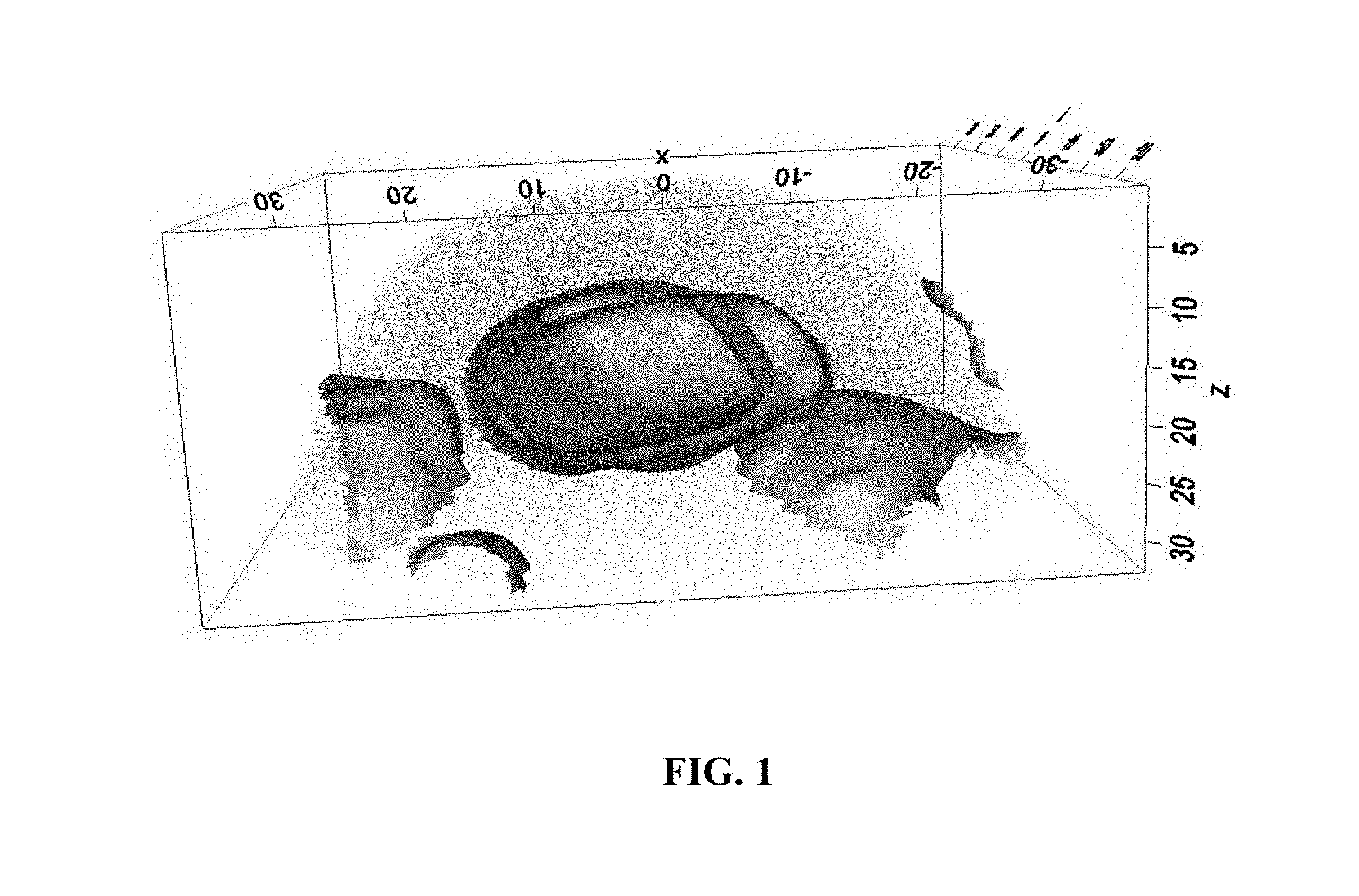
FIG. 1 is a 3-dimensional computer reconstruction of a microstructure of an embodiment of an alloy, produced using atom-probe tomography.
FIG. 2 is a graph plotting the calculated lattice parameters of L1.sub.2, D0.sub.22, and FCC-nickel matrix, as a function of tantalum addition, in weight percentage, for an embodiment of an alloy as described herein including, for example, FIG. 1.
FIG. 3 is a graph plotting the calculated lattice misfit between L1.sub.2, D0.sub.22, and FCC nickel matrix, as a function of tantalum addition, in weight percentage, for an embodiment of an alloy as described herein, including, for example, the alloy of FIG. 1.
FIG. 4 is an equilibrium step diagram of Inconel 625.
FIG. 5 is an equilibrium step diagram of Haynes 282.
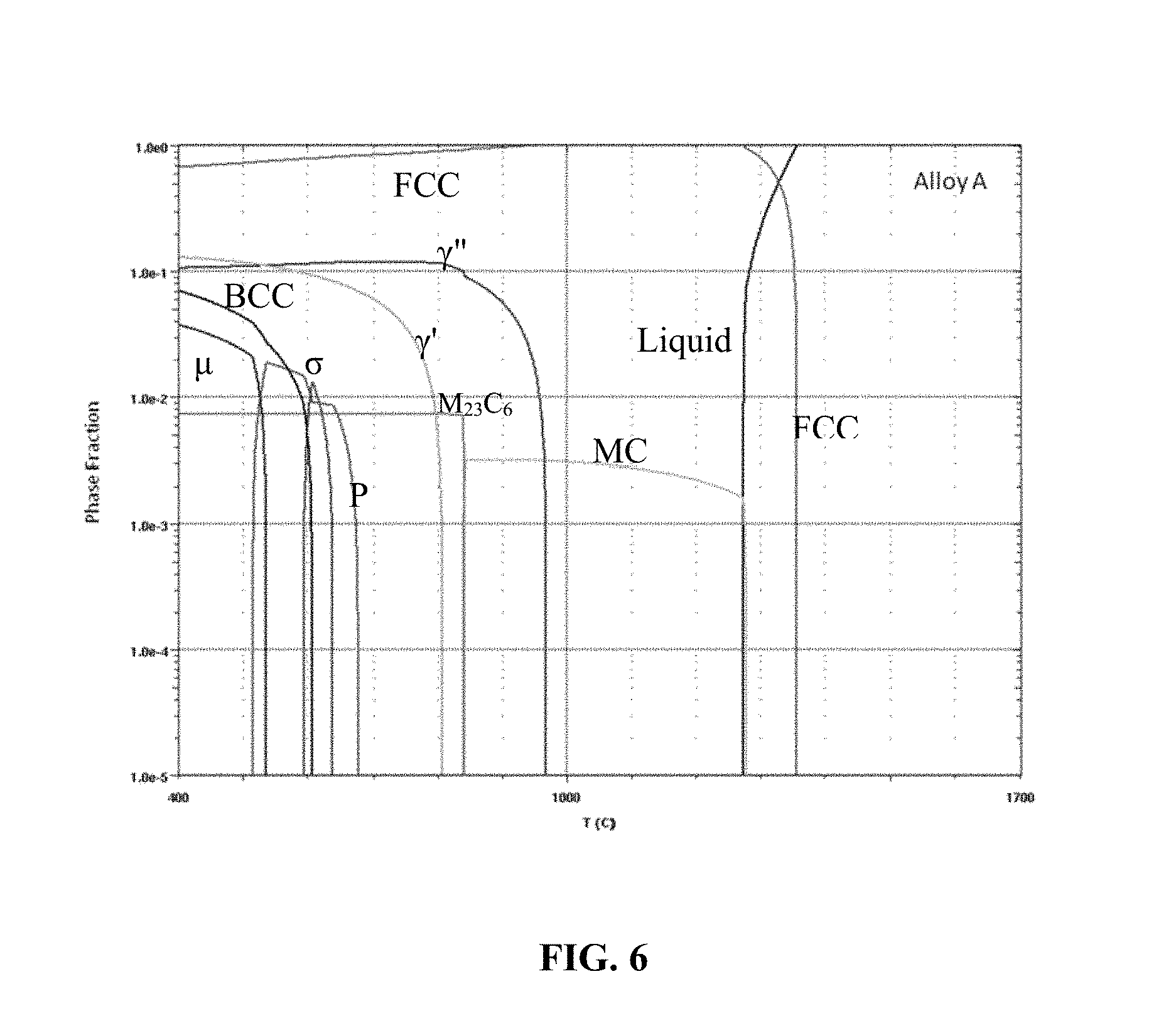
FIG. 6 is an equilibrium step diagram of an embodiment of an alloy as described herein, including, for example, the alloy of FIG. 1.
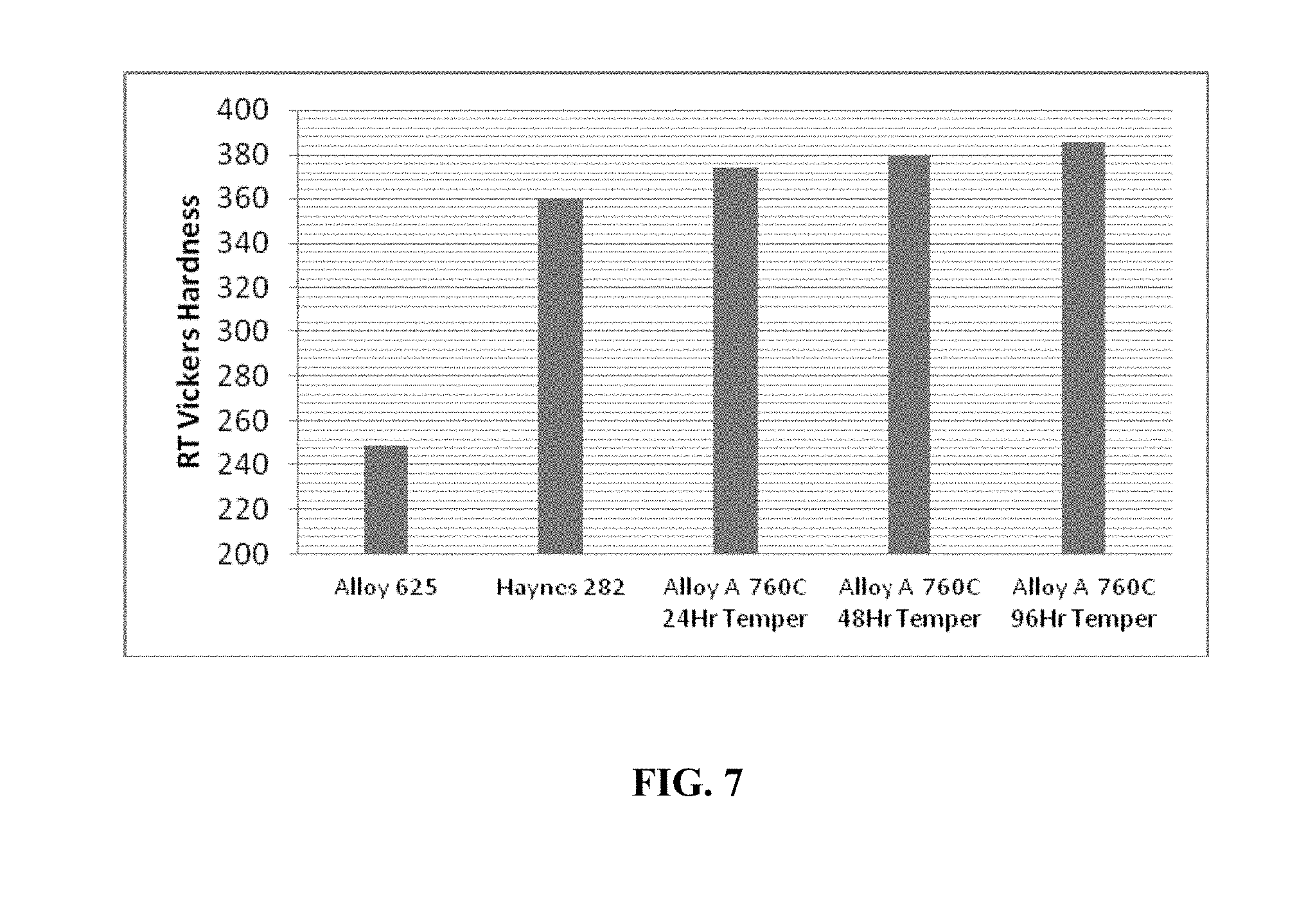
FIG. 7 is a graph plotting the Vickers Hardness Numbers of an embodiment of an alloy as described herein, including, for example, the alloy of FIG. 1, in comparison to aged Inconel 625 and Haynes 282.
DETAILED DESCRIPTION
Aspects relate to alloys, manufactured articles comprising the alloys, and methods for producing the alloys, as described herein.
As used herein, terms such as "face-centered cubic" or "FCC," "L1.sub.2 phase," and "D0.sub.22 phase" include definitions that are generally known in the art.
As Applicants have identified aspects and embodiments that relate to materials including useful ranges of components or elements, any recited range described herein is to be understood to encompass and include all values within that range, without the necessity for an explicit recitation. Use of the word "about" to describe a particular recited amount or range of amounts is meant to indicate that values near to the recited amount are included in that amount, such as, but not limited to, values that could or naturally would be accounted for due to instrument and/or human error in forming measurements, and values that do not substantially affect the properties or nature of the disclosed alloys.
In an aspect, the disclosed alloys are nickel-based and suitably provide high strength at high operating temperatures. In an embodiment, the alloys utilize both D0.sub.22-Ni.sub.3(Nb, Ta) and L1.sub.2-Ni.sub.3(Al, Ti) for strengthening, in a nickel-based FCC matrix. Both precipitates are ordered phases, in which elements appear alternately on crystal lattice sites. During deformation of the alloys, the ordering of the elements is disrupted in the precipitates, giving rise to an antiphase-boundary energy, which can further strengthen the alloys.
According to another aspect, the disclosed alloys provide a high-temperature strength and a thermal conductivity comparable to those of Haynes 282, and can also be suitably brazed on a base metal. In some embodiments, the combination of aluminum and titanium in the alloy is maintained to, by weight, about 0.1% to about 1%. A reason to maintain this weight percent is that aluminum and titanium may form oxides on a brazing surface of the nickel-based alloy. These oxides may interfere with the braze flux, as a result of which the nickel-based alloy may not sufficiently wet with a base metal, leading to a poor braze quality. Although brazing under controlled conditions may improve the surface-wetting, this may increase the cost of operation. The disclosed alloys can be suitably brazed on a base metal with conventional techniques, for example, techniques that are applicable to Inconel 625. Relevant brazing techniques are disclosed in FLAKE C. CAMPBELL, MANUFACTURING TECHNOLOGY FOR AEROSPACE STRUCTURAL MATERIALS 260-263 (2006) (incorporated by reference herein).
In some embodiments, the alloys comprise, in weight percentage, 0% to about 0.01% titanium. Titanium may participate in the formation of undesirable phases such as the .eta. phase. In some embodiments, the addition of titanium is therefore limited to no more than about 0.01% in weight percentage. In further embodiments, titanium is not added in the alloy, such that the strengthening phase L1.sub.2 is formed predominantly of Ni.sub.3Al instead of Ni.sub.3(Al, Ti).
Maintaining the combination of aluminum and titanium to, by weight, about 0.1% to about 1% may have the effect of limiting the volume fraction of the strengthening phase L1.sub.2. In some embodiments, the disclosed alloys therefore provide additional strengthening with D0.sub.22-Ni.sub.3(Nb, Ta) precipitates. In further embodiments, the sum of the volume fractions of L1.sub.2 and D0.sub.22 is comparable to the volume fraction of L1.sub.2 in Haynes 282, namely about 0.134 at about 760.degree. C.
In some embodiments, the disclosed alloys comprise, in weight percentage, about 1.5% to about 6.0% niobium, and about 1.0% to about 3.0% tantalum to form D0.sub.22 precipitates. The addition of niobium and tantalum is not expected to compromise the brazeability of the alloys because these elements are less reactive in air than aluminum or titanium. Moreover, the addition of niobium unexpectedly reduces the solidification temperature range, thereby suitably preventing hot-tearing or hot-cracking during welding. The solidification temperature range may be reduced due to the tendency of niobium to form MC-type carbides in the fusion zone during re-solidification. The addition of tantalum can suitably increase the solvus temperature of the L1.sub.2 phase, retard the coarsening kinetics of the L1.sub.2 precipitates, and increase the creep resistance of the alloy at high temperatures, all of which are desirable for certain high-temperature applications.
In some embodiments, the alloys comprise, in weight percentage, about 3.0% to about 15.0% cobalt. The addition of cobalt can improve the high-temperature strength and maintain a good thermal conductivity for the alloys. As for the alloy strength, cobalt can decrease the solubility of solute elements in the matrix, causing them to precipitate instead of remaining in solid solution. Therefore, by increasing the cobalt content, more solute atoms will form precipitates. Furthermore, the addition of cobalt can increase the driving force for precipitation. Even though cobalt does not substantially partition to the precipitate phases, it nonetheless can increase the overall phase fraction of precipitates at a given amount of L1.sub.2 and D0.sub.22 formers. As for the thermal conductivity, cobalt is similar to nickel in atomic size and thus introduces little lattice distortion to the matrix. Thus, the addition of cobalt does not substantially reduce the thermal conductivity of nickel-based alloys. However, adding more than about 15.0% by weight of cobalt can result in undesirable phases such as .mu. and .sigma..
In some embodiments, the alloys comprise, in weight percentage, 0% to about 5.0% molybdenum, and about 1.0% to about 5.0% tungsten. Molybdenum and tungsten mostly remain in solid solution of the nickel-based matrix. As such, molybdenum and tungsten may provide corrosion resistance for the alloy. Both of these elements, however, have a large atomic size, and may therefore distort the crystal lattice of the matrix. The lattice distortion can reduce the thermal conductivity of the alloy. Furthermore, when added in excessive amounts, molybdenum and tungsten can promote the precipitation of undesirable phases such as the P-phase, or other embrittling, topographically close-packed phases.
In some embodiments, the alloys comprise, in weight percentage, about 1.0% to about 3.0% tantalum. When partitioning to the L1.sub.2, the added tantalum atoms can raise the solvus temperature of the L1.sub.2 phase, which is desirable for certain high-temperature applications. Additionally, the addition of tantalum can increase the phase fraction of the L1.sub.2 phase at a given amount of aluminum and may increase the creep strength of the alloy by reducing the diffusivity within the L1.sub.2 phase. When partitioning to the D0.sub.22, on the other hand, the addition of tantalum may further strengthen the alloys, and also help slowing down the coarsening of the precipitates, thereby maintaining a high strength at high operating temperatures over a period of time. Tantalum may be chemically similar to niobium, because it is in the same group V in the periodic table. Thus, tantalum may readily substitute for niobium in D0.sub.22-Ni.sub.3Nb and form D0.sub.22-Ni.sub.3(Nb, Ta). The atomic size of tantalum, however, is bigger compared to niobium. Thus, tantalum, compared to niobium, may have a slower diffusion coefficient in a nickel matrix. The slower diffusion coefficient is desirable, because it can help slowing down the coarsening of the D0.sub.22-Ni.sub.3(Nb, Ta) precipitates, which in turn can help maintaining a high strength at high operating temperatures over a period of time.
In some embodiments, the alloys comprise, in weight percentage, 0% to about 0.05% carbon. The addition of carbon may facilitate the formation of MC carbide during solidification. The carbide formation may reduce the accumulation of stress during solidification, such as in welding or casting. However, when added in excessive amounts, carbon can promote the formation of M.sub.23C.sub.6, which can embrittle the alloy. Thus, in some embodiments, the alloys comprise, in weight percentage, no more than about 0.05% of carbon.
According to another aspect, the alloys include L1.sub.2 and D0.sub.22 precipitates in a compact morphology, where the D0.sub.22 precipitates substantially or completely enclose an L1.sub.2 precipitate. The D0.sub.22 precipitates may form a diffusion barrier, preventing the growth of the L1.sub.2 precipitate. As described above, D0.sub.22 contains slow-diffusing elements such as niobium and tantalum. Therefore, the D0.sub.22 on the outside of the compact morphology can be helpful in resisting the coarsening of precipitates at high temperatures.
FIG. 1 is a 3-dimensional computer reconstruction of an embodiment with a compact morphology of precipitates, where the D0.sub.22 precipitates (in yellow) surround the L1.sub.2 precipitates (in blue). The numbers in FIG. 1 are in nanometers. In the illustrated embodiment, the compact morphology includes multiple internal interfaces, which may be helpful for strengthening, more so than a dispersion consisting only of L1.sub.2 precipitates.
In some embodiments, the alloys achieve a compact morphology of precipitates when the surface tension between the L1.sub.2 phase and the FCC matrix is greater than the surface tension between the L1.sub.2 phase and D0.sub.22 phase. The alloys may favor a compact morphology of precipitates over a dispersed morphology, if the total strain energy of the former is less than that of the latter. Strain energy in an alloy is generally proportional to the lattice parameter mismatch between the various phases in the alloy. Thus, the total strain energy for an alloy with L1.sub.2 and D0.sub.22 precipitating separately in a dispersed morphology can be approximated by the following equation [1]: G.sub.strain1=A.sub.L1.sub.2.sub.-matrix.gamma..sub.L1.sub.2.sub.-matrix+- A.sub.D0.sub.22.sub.-matrix.gamma..sub.D0.sub.22.sub.-matrix [1] where A.sub.x-y is the boundary area between x and y, and .gamma..sub.x-y is the surface tension between x and y. On the other hand, the total strain energy for an alloy with D0.sub.22 precipitating over L1.sub.2 in a compact morphology can be approximated by the following equation [2]: G.sub.strain2=A.sub.L1.sub.2.sub.-D0.sub.22.gamma..sub.L1.sub.2.sub.-D0.s- ub.22+A.sub.D0.sub.22.sub.-matrix.gamma..sub.D0.sub.22.sub.-matrix [2]
If G.sub.strain1 is greater than G.sub.strain2, the alloy will favor a compact morphology of precipitates to lower its free energy. Assuming A.sub.L1.sub.2.sub.-matrix.apprxeq.A.sub.L1.sub.2.sub.-D0.sub.22, this may mean that if .gamma..sub.L1.sub.2.sub.-matrix>.gamma..sub.L1.sub.2.sub.-D0.sub.22, the alloy will favor a compact morphology of precipitates. Thus, in some embodiments the alloys achieve a compact morphology of precipitates when the surface tension between the L1.sub.2 phase and the FCC matrix is greater than the surface tension between the L1.sub.2 phase and D0.sub.22 phase.
In some embodiments, the lattice parameters of the FCC matrix and the L1.sub.2 and D0.sub.22 precipitates are tuned such that the surface tension between the L1.sub.2 phase and the FCC matrix is greater than the surface tension between the L1.sub.2 phase and D0.sub.22 phase. At room temperature, the lattice parameter of FCC-nickel is about 0.3520 nm, the lattice parameter of L1.sub.2 is about 0.3572 nm, and the lattice parameters of D0.sub.22 are about 0.3542 nm in the basal plane and about 0.7212 nm in a direction normal to the basal plane. In some embodiments, tantalum is added to the alloy such that the surface tensions between the various phases favor a compact morphology of precipitates. The addition of tantalum does not proportionally alter the lattice parameter of D0.sub.22, because the partitioning ratio of tantalum to D0.sub.22 is relatively constant regardless of amount added. Thus, a higher content of tantalum mainly serves to increase the volume fraction of D0.sub.22, without proportionally expanding the lattice parameters of D0.sub.22. On the other hand, the partitioning of tantalum to L1.sub.2 does scale with the overall amount added. That is, the more tantalum is added, the more partitions to the L1.sub.2. Because tantalum has a large atomic size, the higher partitioning can expand the lattice parameter of L1.sub.2. Thus, the addition of tantalum is used in some embodiments to tune the lattice parameter of L1.sub.2 and achieve a balance of lattice parameters that favors a compact morphology of precipitates.
FIG. 2 is a graph plotting the calculated lattice parameters of L1.sub.2, D0.sub.22, and FCC-nickel matrix, as a function of tantalum addition, in weight percentage. FIG. 3 is a graph plotting the calculated lattice misfit between L1.sub.2, D0.sub.22, and FCC-nickel matrix, as a function of tantalum addition, in weight percentage. Adding more than about 3.5% by weight of tantalum can result in the lattice misfit between L1.sub.2 and D0.sub.22 exceeding that between D0.sub.22 and FCC, which may make a compact-morphology formation energetically unfavorable.
In some embodiments, chemical elements such as molybdenum, tungsten, cobalt, and chromium are added to the alloy in amounts suitable to achieve a balance of lattice parameters that favors a compact morphology of precipitates. All of the elements molybdenum, tungsten, cobalt, and chromium mainly partition towards the matrix, and therefore may not substantially affect the lattice parameters of L1.sub.2 and D0.sub.22. Of these elements, those bigger than nickel, namely molybdenum and tungsten, may tend to expand the lattice parameter of the FCC-nickel matrix. On the other hand, those smaller than nickel, namely, cobalt and chromium, may tend to shrink the lattice parameter of the FCC-nickel matrix. Thus, in some embodiments, the amounts of molybdenum, tungsten, cobalt, and chromium are selected to tune the lattice parameter of the FCC-nickel matrix and obtain a balance of lattice parameters that favors a compact morphology of precipitates.
Illustrative embodiments of the alloys are described in greater detail below.
EXAMPLE
Alloy A
A melt was prepared by vacuum ingot metallurgy with the nominal composition, in weight percentage, of about 21.0% Cr, about 3.0% Mo, about 7.0% Co, about 4.0% Nb, about 2.0% Ta, about 3.0% W, about 1.0% Al, about 0.03% C, less than about 1.0% Ti, and the balance essentially Ni and unavoidable impurities. The melt weighed about 300 g. The alloy was homogenized after melting, but not hot-worked. The homogenization heat treatment was performed at about 1125.degree. C. for about 48 hours, followed by quenching with water. The thermal conductivity of alloy 625 is about 0.198 W/cmK, and that of Haynes 282 is about 0.248 W/cmK. The thermal conductivity of Alloy A is expected to be at least that of Haynes 282. Alloy A in the homogenized and quenched state was successfully cold-rolled from a thickness of about 0.090 inches to about 0.017 inches, without any intermediate annealing steps. This represents a thickness reduction exceeding about 80%, and indicates an excellent formability at room temperature. The cold-rolled embodiment recovered nearly all of its strength upon subsequent annealing. An overall thickness reduction from about 60% to about 90% can be achieved for Alloy A by cold-rolling. Alloy A was aged at about 760.degree. C. for about 24, about 48, and about 96 hours, followed by quenching with water.
FIG. 4 is an equilibrium step diagram of Inconel 625. At about 760.degree. C., Inconel 625 has more than about 10% of the .sigma.-phase. FIG. 5 is an equilibrium step diagram of Haynes 282. At 760.degree. C., Haynes 282 has more than about 10% of the .eta.-phase and more than about 1% of the .sigma.-phase. The .sigma.- and the .eta.-phase are generally undesirable, because they form in large sizes and impart little strengthening. They are also brittle and can lock up elements that could otherwise be used for the precipitation of strengthening phases.
FIG. 6 is an equilibrium step diagram of Alloy A. In contrast to Inconel 625 and Haynes 282, Alloy A substantially avoids the undesirable .sigma.- and .eta.-phase at 760.degree. C. By avoiding these phases, the fracture toughness and strength of Alloy A can be increased, which makes Alloy A suitable for components that are exposed to high temperatures for a long time.
FIG. 7 is a graph plotting the Vickers Hardness Number (VHN) of Alloy A. The ambient VHN of Alloy A aged at about 760.degree. C. increased from about 375 to about 385 as the aging duration increased. In comparison, the ambient VHN of Inconel 625 and Haynes 282 in an aged condition measured about 249 and about 360, respectively. An atom-probe tomography of Alloy A in an aged condition showed nanoscale L1.sub.2 and D0.sub.22 precipitates in a compact morphology.
The following Table lists the compositions of two embodiments of the alloys, along with Inconel 625 and Haynes 282. Also listed are the calculated phase fractions of L1.sub.2 and D0.sub.22, the coarsening rate of L1.sub.2, the solvus temperatures of L1.sub.2 and D0.sub.22, the Scheil solidification temperature range, and alloy cost. The alloy cost is estimated by the average market price of the ingredient elements, per pound.
TABLE-US-00001 TABLE Inconel 625 Haynes 282 Alloy A Alloy B Cr 21.5% 20.0% 21.0% 25.0% Mo 8.5% 8.5% 3.0% 0.0% Nb 3.65% 0.00% 4.00% 3.50% Ta 0.00% 2.00% 1.00% Al 0.4% max 1.5% 1.0% 1.0% Ti 0.4% max 2.1% 0.0% 0.0% W 0.0% 0.0% 1.0% 2.5% Co 0% 10% 7% 7% C 0.10% max 0.06% 0.03% 0.03% Fe 5.0% max 1.5% max 0.0% 0.0% Ni balance balance balance balance L1.sub.2 phase fraction 0.000 0.134 0.033 0.021 D0.sub.22 phase fraction 0.007 0.000 0.106 0.088 L1.sub.2 solvus 994.degree. C. 877.degree. C. 874.degree. C. D0.sub.22 solvus 969.degree. C. 976.degree. C. Scheil dT 115.degree. C. 102.degree. C. 91.degree. C. 107.degree. C. Alloy cost $15.34 $11.50 $13.40 $8.10
As described above, the various embodiments of alloys described herein can be used for various applications, including in heat exchangers. In particular, the alloy may provide excellent performance when used to construct fins for a heat exchanger. Such fins may be thin metal plates, or may have another structure. Accordingly, aspects of the subject invention also relate to fins for heat exchangers constructed using an alloy as described herein or a heat exchanger containing such fins, as well as other devices and articles constructed using such an alloy. Aspects of the subject invention may also include methods for manufacturing fins and/or heat exchangers using an alloy as described herein. Such a method for manufacturing a heat exchanger may include manufacturing one or more fins using an alloy as described herein and brazing the fin(s) to a base metal. Further aspects of the subject invention may include a method for creating an alloy as described herein, which may incorporate at least some of the processing steps described above.
It is understood that the invention may embody other specific forms without departing from the spirit or central characteristics thereof. The disclosure of aspects and embodiments, therefore, are to be considered as illustrative and not restrictive. While specific embodiments have been illustrated and described, other modifications may be made without significantly departing from the spirit of the invention.
* * * * *
D00000
D00001
D00002
D00003
D00004
D00005
D00006
D00007
XML
uspto.report is an independent third-party trademark research tool that is not affiliated, endorsed, or sponsored by the United States Patent and Trademark Office (USPTO) or any other governmental organization. The information provided by uspto.report is based on publicly available data at the time of writing and is intended for informational purposes only.
While we strive to provide accurate and up-to-date information, we do not guarantee the accuracy, completeness, reliability, or suitability of the information displayed on this site. The use of this site is at your own risk. Any reliance you place on such information is therefore strictly at your own risk.
All official trademark data, including owner information, should be verified by visiting the official USPTO website at www.uspto.gov. This site is not intended to replace professional legal advice and should not be used as a substitute for consulting with a legal professional who is knowledgeable about trademark law.