Intraocular lens insertion device and cartridge
Inoue Dec
U.S. patent number 10,517,717 [Application Number 15/382,377] was granted by the patent office on 2019-12-31 for intraocular lens insertion device and cartridge. This patent grant is currently assigned to Hoya Corporation. The grantee listed for this patent is Hoya Corporation. Invention is credited to Masanobu Inoue.


| United States Patent | 10,517,717 |
| Inoue | December 31, 2019 |
Intraocular lens insertion device and cartridge
Abstract
An intraocular lens insertion device and a cartridge which enable the intraocular lens to be inserted into an eye more stably and easily than ever before. A supporting portion 102 of an intraocular lens 100 arranged on a lens-advancing side in a lens-advancing direction x is pressed against a protrusion 21 so as to be bent backward. Thus, releasing the intraocular lens 100 from a nozzle portion 13 is allowed to begin with the releasing of a curved portion of the supporting portion 102 that has become U-shaped and hard to move freely. As a result, there can be provided an intraocular lens insertion device and a cartridge which enable the intraocular lens 100 to be inserted into an eye more steadily and easily than ever before.
| Inventors: | Inoue; Masanobu (Honjo, JP) | ||||||||||
|---|---|---|---|---|---|---|---|---|---|---|---|
| Applicant: |
|
||||||||||
| Assignee: | Hoya Corporation (Tokyo,
JP) |
||||||||||
| Family ID: | 41398164 | ||||||||||
| Appl. No.: | 15/382,377 | ||||||||||
| Filed: | December 16, 2016 |
Prior Publication Data
| Document Identifier | Publication Date | |
|---|---|---|
| US 20170151056 A1 | Jun 1, 2017 | |
Related U.S. Patent Documents
| Application Number | Filing Date | Patent Number | Issue Date | ||
|---|---|---|---|---|---|
| 12995263 | 9554894 | ||||
| PCT/JP2009/060184 | Jun 3, 2009 | ||||
Foreign Application Priority Data
| Jun 5, 2008 [JP] | 2008-147781 | |||
| Current U.S. Class: | 1/1 |
| Current CPC Class: | A61F 2/1664 (20130101); A61F 2/167 (20130101); A61F 2/1678 (20130101); A61F 2/1691 (20130101) |
| Current International Class: | A61F 2/16 (20060101) |
References Cited [Referenced By]
U.S. Patent Documents
| 2761446 | September 1956 | Reed |
| 3212685 | October 1965 | Swan |
| 4205747 | June 1980 | Gilliam et al. |
| 4269307 | May 1981 | LaHaye |
| 4423809 | January 1984 | Mazzocco |
| 4573998 | March 1986 | Mazzocco |
| 4608049 | August 1986 | Kelman |
| 4634423 | January 1987 | Bailey |
| 4681102 | July 1987 | Bartell |
| 4697697 | October 1987 | Graham et al. |
| 4699140 | October 1987 | Holmes |
| 4702244 | October 1987 | Mazzocco |
| 4715373 | December 1987 | Mazzocco et al. |
| 4747404 | May 1988 | Jampel et al. |
| 4750498 | June 1988 | Graham |
| 4759359 | July 1988 | Willis et al. |
| 4763650 | August 1988 | Hauser |
| 4765329 | August 1988 | Cumming et al. |
| 4769034 | September 1988 | Poley |
| 4781719 | November 1988 | Kelman |
| 4787904 | November 1988 | Severin |
| 4810249 | March 1989 | Haber et al. |
| 4819631 | April 1989 | Poley |
| 4834094 | May 1989 | Patton |
| 4836201 | June 1989 | Patton |
| 4862885 | September 1989 | Cumming |
| 4880000 | November 1989 | Holmes et al. |
| 4919130 | April 1990 | Stoy et al. |
| 4934363 | June 1990 | Smith et al. |
| 4955889 | September 1990 | Van Gent |
| 4976716 | December 1990 | Cumming |
| 4988352 | January 1991 | Poley |
| 4994028 | February 1991 | Leonard et al. |
| 5066297 | November 1991 | Cumming |
| 5098439 | March 1992 | Hill et al. |
| 5123905 | June 1992 | Kelman |
| 5139501 | August 1992 | Klaas |
| 5171241 | December 1992 | Buboltz et al. |
| 5176686 | January 1993 | Poley |
| 5190552 | March 1993 | Kelman |
| 5190553 | March 1993 | Kanert et al. |
| 5222972 | June 1993 | Hill et al. |
| 5242450 | September 1993 | McDonald |
| 5259395 | November 1993 | Li |
| 5275604 | January 1994 | Rheinish et al. |
| 5281227 | January 1994 | Sussman |
| 5304182 | April 1994 | Rheinish et al. |
| 5354333 | October 1994 | Kammann et al. |
| 5395378 | March 1995 | McDonald |
| 5425734 | June 1995 | Blake |
| 5454818 | October 1995 | Hambleton et al. |
| 5468246 | November 1995 | Blake |
| 5474562 | December 1995 | Orchowski et al. |
| 5494484 | February 1996 | Feingold |
| 5496328 | March 1996 | Nakajima et al. |
| 5499987 | March 1996 | Feingold |
| 5562676 | October 1996 | Brady et al. |
| 5571113 | November 1996 | McDonald |
| 5578042 | November 1996 | Cumming |
| 5582613 | December 1996 | Brady |
| 5582614 | December 1996 | Feingold |
| 5584304 | December 1996 | Brady |
| 5616148 | April 1997 | Eagles et al. |
| 5620450 | April 1997 | Eagles et al. |
| 5643275 | July 1997 | Blake |
| 5643276 | July 1997 | Zaleski |
| 5645534 | July 1997 | Chanoch |
| 5653715 | August 1997 | Reich et al. |
| 5653753 | August 1997 | Brady et al. |
| 5702402 | December 1997 | Brady |
| 5702441 | December 1997 | Zhou |
| 5716364 | February 1998 | Makker et al. |
| 5728075 | March 1998 | Levander |
| 5728102 | March 1998 | Feingold et al. |
| 5735858 | April 1998 | Makker et al. |
| 5766181 | June 1998 | Chambers et al. |
| 5772666 | June 1998 | Feingold et al. |
| 5772667 | June 1998 | Blake |
| 5776138 | July 1998 | Vidal et al. |
| 5800442 | September 1998 | Wolf et al. |
| 5803925 | September 1998 | Yang et al. |
| 5807400 | September 1998 | Chambers et al. |
| 5810833 | September 1998 | Brady et al. |
| 5810834 | September 1998 | Heyman |
| 5860984 | January 1999 | Chambers et al. |
| 5860986 | January 1999 | Reich et al. |
| 5868751 | February 1999 | Feingold |
| 5868752 | February 1999 | Makker et al. |
| 5873879 | February 1999 | Figueroa et al. |
| 5876406 | March 1999 | Wolf et al. |
| 5876407 | March 1999 | Makker et al. |
| 5876440 | March 1999 | Feingold |
| 5891152 | April 1999 | Feingold |
| 5902307 | May 1999 | Feingold et al. |
| 5919197 | July 1999 | McDonald |
| 5921989 | July 1999 | Deacon et al. |
| 5928245 | July 1999 | Wolf et al. |
| 5941886 | August 1999 | Feingold |
| 5942277 | August 1999 | Makker et al. |
| 5944725 | August 1999 | Cicenas |
| 5947974 | September 1999 | Brady et al. |
| 5947975 | September 1999 | Kikuchi et al. |
| 5957748 | September 1999 | Ichiha |
| 5957896 | September 1999 | Bendek et al. |
| 6001107 | December 1999 | Feingold |
| 6010510 | January 2000 | Brown et al. |
| 6022358 | February 2000 | Wolf et al. |
| 6048348 | April 2000 | Chambers et al. |
| 6050999 | April 2000 | Paraschac et al. |
| 6051000 | April 2000 | Heyman |
| 6056757 | May 2000 | Feingold et al. |
| 6056758 | May 2000 | Vidal et al. |
| 6059791 | May 2000 | Chambers |
| 6074397 | June 2000 | Chambers et al. |
| 6083230 | July 2000 | Makker et al. |
| 6093193 | July 2000 | Makker et al. |
| 6129733 | October 2000 | Brady et al. |
| 6142999 | November 2000 | Brady et al. |
| 6143000 | November 2000 | Feingold |
| 6162229 | December 2000 | Feingold et al. |
| 6174315 | January 2001 | Chambers et al. |
| 6214015 | April 2001 | Reich et al. |
| 6241737 | June 2001 | Feingold |
| 6248111 | June 2001 | Glick et al. |
| 6251114 | June 2001 | Farmer et al. |
| 6254607 | July 2001 | Makker et al. |
| 6267768 | July 2001 | Deacon |
| 6283975 | September 2001 | Glick et al. |
| 6283976 | September 2001 | Portney |
| 6312433 | November 2001 | Butts |
| 6334862 | January 2002 | Vidal et al. |
| 6336932 | January 2002 | Figueroa et al. |
| 6355046 | March 2002 | Kikuchi et al. |
| 6371960 | April 2002 | Heyman et al. |
| 6386357 | May 2002 | Egawa |
| 6387101 | May 2002 | Butts et al. |
| 6398788 | June 2002 | Makker et al. |
| 6406481 | June 2002 | Feingold et al. |
| 6428545 | August 2002 | Portney |
| 6447519 | September 2002 | Brady et al. |
| 6447520 | September 2002 | Ott et al. |
| 6468282 | October 2002 | Kikuchi et al. |
| 6471708 | October 2002 | Green |
| 6491697 | December 2002 | Clark et al. |
| 6497708 | December 2002 | Cumming |
| 6500181 | December 2002 | Portney |
| 6506195 | January 2003 | Chambers et al. |
| 6537283 | March 2003 | Van Noy |
| 6540754 | April 2003 | Brady |
| 6554839 | April 2003 | Brady |
| 6558395 | May 2003 | Hjertman et al. |
| 6605093 | August 2003 | Blake |
| 6607537 | August 2003 | Binder |
| 6629979 | October 2003 | Feingold |
| 6666871 | December 2003 | Kikuchi et al. |
| 6679891 | January 2004 | Makker et al. |
| 6685740 | February 2004 | Figueroa et al. |
| 6712848 | March 2004 | Wolf et al. |
| 6723104 | April 2004 | Ott |
| 6733507 | May 2004 | McNicholas et al. |
| 6793674 | September 2004 | Zapata |
| 6858033 | February 2005 | Kobayashi |
| 6921405 | July 2005 | Feingold et al. |
| 6923815 | August 2005 | Brady et al. |
| 6976989 | December 2005 | Vincent |
| 7014641 | March 2006 | Kobayashi et al. |
| 7025782 | April 2006 | Kobayashi et al. |
| 7033366 | April 2006 | Brady |
| 7037312 | May 2006 | Kikuchi et al. |
| 7074227 | July 2006 | Portney |
| 7097649 | August 2006 | Meyer |
| 7131976 | November 2006 | Kobayashi et al. |
| 7156854 | January 2007 | Brown et al. |
| 7348038 | March 2008 | Makker et al. |
| 7422604 | September 2008 | Vaquero et al. |
| 7429263 | September 2008 | Vaquero et al. |
| 7458976 | December 2008 | Peterson et al. |
| 7476230 | January 2009 | Ohno et al. |
| 7494505 | February 2009 | Kappelhof et al. |
| 7645300 | January 2010 | Tsai |
| 8273122 | September 2012 | Anderson |
| 8382769 | February 2013 | Inoue |
| 8460311 | June 2013 | Ishii |
| 8470032 | June 2013 | Inoue et al. |
| 8475526 | July 2013 | Pynson |
| 8475528 | July 2013 | Ichinohe et al. |
| 8523877 | September 2013 | Ichinohe et al. |
| 8523941 | September 2013 | Ichinohe et al. |
| 8535375 | September 2013 | Ichinohe et al. |
| 8545512 | October 2013 | Ichinohe et al. |
| 8574239 | November 2013 | Ichinohe et al. |
| 8603103 | December 2013 | Kudo et al. |
| 8647382 | February 2014 | Kudo et al. |
| 8702795 | April 2014 | Shoji et al. |
| 8747465 | June 2014 | Someya et al. |
| 8968328 | March 2015 | Ichinohe et al. |
| 9114006 | August 2015 | Inoue |
| 9114007 | August 2015 | Ichinohe et al. |
| 9186246 | November 2015 | Inoue |
| 9220593 | December 2015 | Ichinohe |
| 9289288 | March 2016 | Someya et al. |
| 9314373 | April 2016 | Kudo et al. |
| 9326847 | May 2016 | Demas |
| 9364320 | June 2016 | Ichinohe et al. |
| 9554894 | January 2017 | Inoue |
| 9572710 | February 2017 | Kudo et al. |
| 9655718 | May 2017 | Kudo |
| 9687340 | June 2017 | Anderson |
| 9877826 | January 2018 | Kudo et al. |
| 9901442 | February 2018 | Kudo et al. |
| 9907647 | March 2018 | Inoue |
| 9998081 | May 2018 | Kudo et al. |
| 1003966 | August 2018 | Kudo et al. |
| 2001/0007942 | July 2001 | Kikuchi et al. |
| 2002/0103490 | August 2002 | Brady |
| 2002/0151904 | October 2002 | Feingold et al. |
| 2002/0165610 | November 2002 | Waldock |
| 2002/0193805 | December 2002 | Ott et al. |
| 2003/0036765 | February 2003 | Van Noy |
| 2003/0040755 | February 2003 | Meyer |
| 2003/0050647 | March 2003 | Brady |
| 2003/0088253 | May 2003 | Seil |
| 2003/0139749 | July 2003 | Kikuchi et al. |
| 2003/0181921 | September 2003 | Jeannin |
| 2003/0195522 | October 2003 | McNicholas |
| 2003/0212406 | November 2003 | Kobayashi et al. |
| 2003/0212407 | November 2003 | Kikuchi |
| 2003/0212408 | November 2003 | Kobayashi |
| 2003/0212409 | November 2003 | Kobayashi et al. |
| 2004/0111094 | June 2004 | Meyer |
| 2004/0117012 | June 2004 | Vincent |
| 2004/0127911 | July 2004 | Figueroa |
| 2004/0147938 | July 2004 | Dusek et al. |
| 2004/0186428 | September 2004 | Ray |
| 2004/0238392 | December 2004 | Peterson et al. |
| 2004/0243141 | December 2004 | Brown et al. |
| 2005/0033308 | February 2005 | Callahan et al. |
| 2005/0049605 | March 2005 | Vaquero et al. |
| 2005/0049606 | March 2005 | Vaquero et al. |
| 2005/0055011 | March 2005 | Enggaard |
| 2005/0125000 | June 2005 | Tourrette et al. |
| 2005/0143750 | June 2005 | Vaquero |
| 2005/0182419 | August 2005 | Tsai |
| 2005/0222578 | October 2005 | Vaquero |
| 2005/0261703 | November 2005 | Feingold et al. |
| 2006/0085013 | April 2006 | Dusek |
| 2006/0142781 | June 2006 | Pynson et al. |
| 2006/0167466 | July 2006 | Dusek |
| 2006/0200167 | September 2006 | Peterson |
| 2006/0229633 | October 2006 | Shepherd |
| 2006/0235429 | October 2006 | Lee et al. |
| 2006/0293694 | December 2006 | Futamura |
| 2007/0005135 | January 2007 | Makker et al. |
| 2007/0270945 | November 2007 | Kobayashi |
| 2008/0033449 | February 2008 | Cole |
| 2008/0058830 | March 2008 | Cole et al. |
| 2008/0086146 | April 2008 | Ishii et al. |
| 2008/0097459 | April 2008 | Kammerlander et al. |
| 2008/0221584 | September 2008 | Downer |
| 2009/0036898 | February 2009 | Ichinohe |
| 2009/0043313 | February 2009 | Ichinohe |
| 2009/0112223 | April 2009 | Downer et al. |
| 2009/0125034 | May 2009 | Pynson |
| 2009/0138022 | May 2009 | Tu et al. |
| 2009/0204122 | August 2009 | Ichinohe et al. |
| 2009/0216244 | August 2009 | Pynson |
| 2009/0248031 | October 2009 | Ichinohe |
| 2009/0270876 | October 2009 | Hoffmann |
| 2010/0094309 | April 2010 | Hboukhny et al. |
| 2010/0106160 | April 2010 | Tsai |
| 2010/0161049 | June 2010 | Inoue |
| 2010/0185206 | July 2010 | Ichinohe et al. |
| 2010/0217273 | August 2010 | Someya et al. |
| 2010/0286704 | November 2010 | Ichinohe et al. |
| 2010/0331808 | December 2010 | Py et al. |
| 2011/0046633 | February 2011 | Pankin et al. |
| 2011/0046635 | February 2011 | Pankin et al. |
| 2011/0082463 | April 2011 | Inoue |
| 2011/0098717 | April 2011 | Inoue |
| 2011/0172676 | July 2011 | Chen |
| 2011/0264101 | October 2011 | Inoue et al. |
| 2011/0270264 | November 2011 | Shoji et al. |
| 2011/0288557 | November 2011 | Kudo et al. |
| 2012/0022549 | January 2012 | Someya et al. |
| 2012/0071887 | March 2012 | Ichinohe et al. |
| 2012/0123438 | May 2012 | Horvath et al. |
| 2013/0006259 | January 2013 | Sanger |
| 2013/0018460 | January 2013 | Anderson |
| 2013/0085507 | April 2013 | Nagasaka |
| 2013/0226193 | August 2013 | Kudo et al. |
| 2013/0245635 | September 2013 | Inoue |
| 2013/0345713 | December 2013 | Cole et al. |
| 2014/0081284 | March 2014 | Ichinohe et al. |
| 2014/0107660 | April 2014 | Ichinohe et al. |
| 2014/0114323 | April 2014 | Kudo et al. |
| 2014/0135784 | May 2014 | Maroscheck |
| 2014/0180299 | June 2014 | Ichinohe et al. |
| 2014/0180300 | June 2014 | Ichinohe et al. |
| 2014/0194890 | July 2014 | Kudo et al. |
| 2014/0276901 | September 2014 | Auld |
| 2015/0327992 | November 2015 | Wagner et al. |
| 2016/0113759 | April 2016 | Inoue |
| 2016/0151150 | June 2016 | Sato |
| 2016/0193038 | July 2016 | Kudo et al. |
| 2016/0270907 | September 2016 | Attinger |
| 2016/0331587 | November 2016 | Yamada et al. |
| 2016/0346077 | December 2016 | Someya et al. |
| 2017/0079772 | March 2017 | Kudo |
| 2017/0202662 | July 2017 | Someya et al. |
| 2017/0252149 | September 2017 | Kudo et al. |
| 2017/0252150 | September 2017 | Kudo et al. |
| 2017/0258582 | September 2017 | Kudo et al. |
| 2017/0354493 | December 2017 | Andersen et al. |
| 2018/0250125 | September 2018 | Kudo et al. |
| 2018/0353287 | December 2018 | Kudo et al. |
| 2019/0151078 | May 2019 | Watanabe et al. |
| 2019/0192284 | June 2019 | Watanabe et al. |
| 3610925 | Oct 1987 | DE | |||
| 4110278 | Oct 1992 | DE | |||
| 19544119 | May 1997 | DE | |||
| 0363213 | Apr 1990 | EP | |||
| 0727966 | Sep 2003 | EP | |||
| 1360947 | Nov 2003 | EP | |||
| 1832247 | Sep 2007 | EP | |||
| 1338254 | Dec 2008 | EP | |||
| 2074961 | Jul 2009 | EP | |||
| 2255751 | Dec 2010 | EP | |||
| 2286763 | Feb 2011 | EP | |||
| 2286764 | Feb 2011 | EP | |||
| 2574308 | Apr 2013 | EP | |||
| 2749752 | Dec 1997 | FR | |||
| 63-197453 | Aug 1988 | JP | |||
| 4-212350 | Aug 1992 | JP | |||
| 5-103808 | Apr 1993 | JP | |||
| 5-103809 | Apr 1993 | JP | |||
| 8-024282 | Jan 1996 | JP | |||
| 8-505540 | Jun 1996 | JP | |||
| 9-506285 | Jun 1997 | JP | |||
| 11-113939 | Apr 1999 | JP | |||
| 11-506357 | Jun 1999 | JP | |||
| 2000-516487 | Dec 2000 | JP | |||
| 2000-516488 | Dec 2000 | JP | |||
| 2001-502563 | Feb 2001 | JP | |||
| 2001-104347 | Apr 2001 | JP | |||
| 2002-516709 | Jun 2002 | JP | |||
| 2002-355268 | Dec 2002 | JP | |||
| 2002-541912 | Dec 2002 | JP | |||
| 2003-144480 | May 2003 | JP | |||
| 3412106 | Jun 2003 | JP | |||
| 2003-210498 | Jul 2003 | JP | |||
| 2003-325569 | Nov 2003 | JP | |||
| 2003-325570 | Nov 2003 | JP | |||
| 2003-325572 | Nov 2003 | JP | |||
| 2004-024854 | Jan 2004 | JP | |||
| 2004-188194 | Jul 2004 | JP | |||
| 2004-351196 | Dec 2004 | JP | |||
| 2006-181269 | Jul 2006 | JP | |||
| 2006-297146 | Nov 2006 | JP | |||
| 2006-333924 | Dec 2006 | JP | |||
| 2006-333981 | Dec 2006 | JP | |||
| 2007-503872 | Mar 2007 | JP | |||
| 2007-152010 | Jun 2007 | JP | |||
| 2007-181604 | Jul 2007 | JP | |||
| 2007-244570 | Sep 2007 | JP | |||
| 2007-526091 | Sep 2007 | JP | |||
| 2007-307168 | Nov 2007 | JP | |||
| 2008-521535 | Jun 2008 | JP | |||
| 2008-212689 | Sep 2008 | JP | |||
| 2014-050484 | Mar 2014 | JP | |||
| 2016-137122 | Aug 2016 | JP | |||
| WO9407436 | Apr 1994 | WO | |||
| WO9513022 | May 1995 | WO | |||
| WO9628122 | Sep 1996 | WO | |||
| WO9715253 | May 1997 | WO | |||
| WO9812969 | Apr 1998 | WO | |||
| WO9958086 | Nov 1999 | WO | |||
| WO9959668 | Nov 1999 | WO | |||
| WO0045746 | Aug 2000 | WO | |||
| WO0062712 | Oct 2000 | WO | |||
| WO2002071982 | Sep 2002 | WO | |||
| WO2002096322 | Dec 2002 | WO | |||
| WO2005023154 | Mar 2005 | WO | |||
| WO2005070341 | Aug 2005 | WO | |||
| WO2005084588 | Sep 2005 | WO | |||
| WO2006070628 | Jul 2006 | WO | |||
| WO2006080191 | Aug 2006 | WO | |||
| WO2006090531 | Aug 2006 | WO | |||
| WO2007037223 | Apr 2007 | WO | |||
| WO2007097221 | Apr 2007 | WO | |||
| WO2007080869 | Jul 2007 | WO | |||
| WO2008149794 | Dec 2008 | WO | |||
| WO2008149795 | Dec 2008 | WO | |||
| WO2009058929 | Jul 2009 | WO | |||
| WO2009148091 | Dec 2009 | WO | |||
| WO2011126144 | Oct 2011 | WO | |||
| WO2011155636 | Dec 2011 | WO | |||
| WO2012155887 | Nov 2012 | WO | |||
| WO2015012312 | Jan 2015 | WO | |||
Other References
|
US. Appl. No. 15/071,880, filed Mar. 16, 2016, US 20160193038A1. cited by applicant . U.S. Appl. No. 14/812,104, filed Jul. 29, 2015, US 20160113759A1. cited by applicant . U.S. Appl. No. 15/608,895, filed May 30, 2017, US 20170258582A1. cited by applicant . U.S. Appl. No. 15/600,679, filed May 19, 2017, US 20170252149A1. cited by applicant . U.S. Appl. No. 15/600,684, filed May 19, 2017, US 20170252150A1. cited by applicant . U.S. Appl. No. 12/995,263, filed Dec. 15, 2010, US 20110082463A1. cited by applicant . U.S. Appl. No. 15/336,678, filed Oct. 27, 2016. cited by applicant . U.S. Appl. No. 14/099,989, filed Dec. 8, 2013, US 20140194890A1. cited by applicant . U.S. Appl. No. 15/126,277, filed Sep. 14, 2016. cited by applicant . U.S. Appl. No. 15/888,078, filed Feb. 4, 2018. cited by applicant . U.S. Appl. No. 15/870,979, filed Jan. 14, 2018. cited by applicant . U.S. Appl. No. 15/756,565, filed Feb. 28, 2018. cited by applicant . U.S. Appl. No. 15/756,569, filed Feb. 28, 2018. cited by applicant . U.S. Appl. No. 16/313,180, filed Dec. 26, 2018. cited by applicant . U.S. Appl. No. 16/313,184, filed Dec. 26, 2018. cited by applicant . U.S. Appl. No. 12/602,442, filed Dec. 15, 2009, U.S. Pat. No. 8,747,465. cited by applicant . U.S. Appl. No. 13/244,449, filed Sep. 24, 2011, U.S. Pat. No. 9,289,288. cited by applicant . U.S. Appl. No. 15/063,395, filed Mar. 7, 2016, US 20160346077A1. cited by applicant . U.S. Appl. No. 15/476,717, filed Mar. 31, 2017, US 20170202662A1. cited by applicant . U.S. Appl. No. 12/602,454, filed Dec. 15, 2009, U.S. Pat. No. 8,475,528. cited by applicant . U.S. Appl. No. 13/244,452, filed Sep. 24, 2011, U.S. Pat. No. 8,535,375. cited by applicant . U.S. Appl. No. 12/667,510, filed Dec. 31, 2009, U.S. Pat. No. 9,114,006. cited by applicant . U.S. Appl. No. 14/812,104, filed Jul. 29, 2015, U.S. Pat. No. 9,907,647. cited by applicant . U.S. Appl. No. 12/995,263, filed Dec. 15, 2010, U.S. Pat. No. 9,554,894. cited by applicant . U.S. Appl. No. 12/997,651, filed Dec. 13, 2010, U.S. Pat. No. 8,382,769. cited by applicant . U.S. Appl. No. 13/757,790, filed Feb. 2, 2012, U.S. Pat. No. 9,186,246. cited by applicant . U.S. Appl. No. 13/583,216, filed Apr. 6, 2011, U.S. Pat. No. 9,326,847. cited by applicant . U.S. Appl. No. 13/699,708, filed Jun. 8, 2011, U.S. Pat. No. 8,647,382. cited by applicant . U.S. Appl. No. 14/145,846, filed Dec. 31, 2013, U.S. Pat. No. 9,314,373. cited by applicant . U.S. Appl. No. 15/071,880, filed Mar. 16, 2016, U.S. Pat. No. 10,039,668. cited by applicant . U.S. Appl. No. 15/336,678, filed Oct. 27, 2016, U.S. Pat. No. 9,572,710. cited by applicant . U.S. Appl. No. 15/608,895, filed May 30, 2017, U.S. Pat. No. 9,980,811. cited by applicant . U.S. Appl. No. 13/059,401, filed Feb. 16, 2011, U.S. Pat. No. 8,702,795. cited by applicant . U.S. Appl. No. 13/061,143, filed Feb. 26, 2011, U.S. Pat. No. 8,470,032. cited by applicant . U.S. Appl. No. 13/143,322, filed Jul. 5, 2011, U.S. Pat. No. 8,603,103. cited by applicant . U.S. Appl. No. 14/099,989, filed Dec. 8, 2013, U.S. Pat. No. 9,655,718. cited by applicant . U.S. Appl. No. 15/600,679, filed May 19, 2017, U.S. Pat. No. 9,877,826. cited by applicant . U.S. Appl. No. 15/600,684, filed May 19, 2017, U.S. Pat. No. 9,901,442. cited by applicant . U.S. Appl. No. 11/814,508, filed Jul. 23, 2007, U.S. Pat. No. 8,545,512. cited by applicant . U.S. Appl. No. 14/033,888, filed Sep. 23, 2013, U.S. Pat. No. 9,220,593. cited by applicant . U.S. Appl. No. 11/816,676, filed Aug. 20, 2007, U.S. Pat. No. 8,523,877. cited by applicant . U.S. Appl. No. 13/966,209, filed Aug. 13, 2013, U.S. Pat. No. 9,364,320. cited by applicant . U.S. Appl. No. 12/095,172, filed May 28, 2008, U.S. Pat. No. 8,523,941. cited by applicant . U.S. Appl. No. 14/011,018, filed Aug. 27, 2013, U.S. Pat. No. 8,968,328. cited by applicant . U.S. Appl. No. 12/088,328, filed Mar. 27, 2008, U.S. Pat. No. 8,574,239. cited by applicant . U.S. Appl. No. 14/065,365, filed Oct. 28, 2013, U.S. Pat. No. 9,114,007. cited by applicant . U.S. Appl. No. 11/722,601, filed Apr. 10, 2008, U.S. Pat. No. 8,460,311. cited by applicant . U.S. Appl. No. 15/126,277, filed Sep. 14, 2016, US 20170079772A1. cited by applicant . U.S. Appl. No. 15/756,565, filed Feb. 28, 2018, US 20180250125A1. cited by applicant . U.S. Appl. No. 15/756,569, filed Feb. 28, 2018, US 20180353287A1. cited by applicant . U.S. Appl. No. 16/313,180, filed Dec. 26, 2018, US 20190192284A1. cited by applicant . U.S. Appl. No. 16/313,184, filed Dec. 26, 2018, US 20190151078A1. cited by applicant. |
Primary Examiner: Simpson; Sarah A
Attorney, Agent or Firm: Henricks Slavin LLP
Parent Case Text
CROSS-REFERENCE TO RELATED APPLICATIONS
This application is a continuation of U.S. application Ser. No. 12/995,263, now U.S. Pat. No. 9,554,894, which has a 35 U.S.C. .sctn. 371(c) date of Dec. 15, 2010 and is a U.S. national phase application under 35 U.S.C. .sctn. 371 of International Patent Application No. PCT/JP2009/060184, filed Jun. 3, 2009, which claims priority to Japanese patent application No. 2008-147781, filed Jun. 5, 2008. The content of each application is incorporated herein in its entirety.
Claims
The invention claimed is:
1. An apparatus for use with an intraocular lens that includes an optical portion and first and second support portions, the apparatus comprising: a tubular member including a lens placement portion, a nozzle that is configured to be inserted into an eye, a plunger that moves in a lens advancement direction toward the nozzle, and an inner surface defining an internal lumen that extends from the lens placement portion to the nozzle and through which the plunger and the intraocular lens travel in the lens advancement direction; and means for moving in and out of the internal lumen through which the plunger and the intraocular lens travel and, when in the internal lumen, contacting and bending the first support portion in a direction opposite the lens advancement direction as the intraocular lens travels though the internal lumen in the lens advancement direction with the first support portion ahead of the second support portion such that the first support portion remains bent when it enters the nozzle.
2. An apparatus as claimed in claim 1, wherein the tubular member comprises a portion of an intraocular lens cartridge.
3. An apparatus as claimed in claim 2, wherein the means for moving, contacting and bending is located on a cartridge case.
4. An apparatus as claimed in claim 1, wherein the tubular member comprises a portion of an intraocular lens insertion device.
5. An apparatus as claimed in claim 4, wherein the means for moving, contacting and bending is located on an insertion device case.
6. An apparatus for use with an intraocular lens that includes an optical portion and first and second support portions, the apparatus comprising: a tubular member including a lens placement portion, a nozzle that is configured to be inserted into an eye, a plunger that moves in a lens advancement direction toward the nozzle, and an inner surface defining an internal lumen that extends from the lens placement portion to the nozzle and through which the plunger and the intraocular lens travel in the lens advancement direction; and means for moving in and out of the internal lumen through which the plunger and the intraocular lens travel at a contact location and, when in the internal lumen at the contact location, contacting and bending the first support portion in a direction opposite the lens advancement direction as the intraocular lens travels though the internal lumen in the lens advancement direction with the first support portion ahead of the second support portion such that the first support portion remains bent when it enters the nozzle; wherein the respective configurations of the internal lumen and the contact location are such that the intraocular lens optical portion abuts the means for moving, contacting and bending at the contact location as the intraocular lens travels though the internal lumen in the lens advancement direction.
7. An apparatus as claimed in claim 6, wherein the tubular member comprises a portion of an intraocular lens cartridge.
8. An apparatus as claimed in claim 7, wherein the means for moving, contacting and bending is located on a cartridge case.
9. An apparatus as claimed in claim 6, wherein the tubular member comprises a portion of an intraocular lens insertion device.
10. An apparatus as claimed in claim 9, wherein the means for moving, contacting and bending is located on an insertion device case.
Description
TECHNICAL FIELD
This invention relates to an intraocular lens insertion device and a cartridge thereof that are used when implanting an intraocular lens into an aphakic eye after a cataract operation.
BACKGROUND ART
In a cataract operation, removing an opacified lens by phacoemulsification (PEA), and implanting an intraocular lens after removing an opacified lens are widely performed. Intraocular lenses include: a hard intraocular lens whose optical portion is made of a hard material such as PMMA (polymethylmethacrylate), and a soft intraocular lens which is made of a soft material such as silicone elastomer, soft acrylic, or hydrogel.
When using a hard intraocular lens, the intraocular lens must be inserted through an incision formed in the cornea or sclera that is of the same or slightly wider width than the diameter of the optical portion. On the other hand, when using a soft intraocular lens, folding of the optical portion allows the intraocular lens to be inserted into the eye through an incision smaller than the diameter of the optical portion.
FIGS. 12(A) and 12(B) show a soft intraocular lens of this kind. A front view is shown in FIG. 12(A) and a side view is shown in FIG. 12(B). In practice, a soft intraocular lens 100 of this kind is formed in a flat circular shape and comprises an optical portion 101 serving as a crystalline lens in an eyeball and two supporting portions 102, 102 formed in a linear shape. These two supporting portions 102, 102 are provided at two symmetrically opposite sections on the circumference of the optical portion 101. The supporting portions 102, 102 are extended in the form of a circular arc in such a manner as gradually departing away from the outer fringe of the optical portion 101 at a curvature slightly larger than that of the outer fringe of the optical portion 101.
The soft intraocular lens 100 of this kind is designed so as to be able to be inserted through a small incision into an eye after the optical portion 101 thereof is folded in two by an intraocular lens insertion device disclosed, for example, in Intl Application Publication Pamphlet of WO2006/090531 or Japanese Unexamined Patent Application Publication No. 2004-351196. Patent Document 1: WO2006/090531 Intl Application Publication Pamphlet Patent Document 2: Japanese Unexamined Patent Application Publication No. 2004-351196
DISCLOSURE OF THE INVENTION
Problems to be Solved by the Invention
According to these conventional intraocular insertion devices, however, there is a problem that proficiency is required to insert the intraocular lens 100 into the eye while keeping the distal end of the supporting portion 102 stable because when inserting the intraocular lens 100 into a lens capsule C inside an eyeball E, the distal end of the supporting portion 102 is foremost discharged from a discharge port 104, as shown in FIG. 13, and thus the distal end of the supporting portion 102 is prone to be moved freely.
In view of the problem described above, it is, therefore, an object of the present invention to provide an intraocular lens insertion device and cartridge thereof which enable an intraocular lens to be inserted into an eye more easily and more stably as compared to by the conventional ones.
Means for Solving the Problem
In order to achieve the object of the present invention, the present invention according to a first aspect is characterized by an intraocular lens insertion device comprising:
an cylindrical insertion portion to place therein an intraocular lens having one or more supporting portions provided on an outer fringe of an optical portion thereof, said intraocular lens insertion device pushing out said intraocular lens by a plunger, and then releasing said intraocular lens to an outside from a nozzle portion of said cylindrical insertion portion,
wherein said supporting portion arranged on an advancing side with respect to a lens-advancing direction is bent backward by a bending means in said cylindrical insertion portion.
The present invention according to a second aspect is characterized in that said bending means is a protrusion while said supporting portion is pressed against said protrusion to be bent backward.
The present invention according to a third aspect is characterized in that said protrusion is detachably provided in said cylindrical insertion portion.
The present invention according to a fourth aspect is characterized in that said protrusion is provided in a separate casing while said casing is detachably attached to said cylindrical insertion portion.
The present invention according to a fifth aspect is characterized in that said plunger is provided in a main body of the insertion device, while said cylindrical insertion portion is a cartridge attached to said main body of the insertion device,
wherein said cartridge is separated from said casing and attached to said main body of the insertion device after said supporting portion of the intraocular lens placed on a lens placement portion is bent by said protrusion.
The present invention according to a sixth aspect is characterized in that said intraocular lens is of a preset type with said intraocular lens set in advance.
The present invention according to a seventh aspect is characterized by a cartridge attached to a main body of an insertion device provided with a plunger for pushing out an intraocular lens having one or more supporting portions provided on an outer fringe of an optical portion thereof, comprising:
a lens placement portion to place therein said intraocular lens from a lens insertion opening;
a nozzle portion communicating with said lens placement portion to release said intraocular lens to an outside,
wherein said supporting portion arranged on an advancing side with respect to a lens-advancing direction is bent backward by a bending means in said lens placement portion.
The present invention according to an eighth aspect is characterized in that said bending means is a protrusion while said supporting portion is pressed against said protrusion to be bent backward.
The present invention according to a ninth aspect is characterized in that said protrusion is detachably provided in said lens placement portion.
The present invention according to a tenth aspect is characterized in that said protrusion is provided in a separate casing while said casing is detachably attached to said lens placement portion.
The present invention according to an eleventh aspect is characterized in that said cartridge is separated from said casing and attached to said main body of the insertion device after said supporting portion of the intraocular lens placed on said lens placement portion is bent by said protrusion.
Effects of the Invention
In accordance with the intraocular lens insertion device according to the first aspect and the cartridge according to the seventh aspect, the supporting portion of the intraocular lens placed on the lens advancing side is bent backward by the bending means, thus enabling the intraocular lens to be released after it is folded and made less likely to move freely when it is released from the nozzle. Thus, the intraocular lens can be more easily inserted into an eye with the same kept in a more stable condition than by the conventional ones.
In accordance with the intraocular lens insertion device according to the third aspect and the cartridge according to the ninth aspect, it is possible to prevent the protrusion from blocking the movement when inserting the intraocular lens into an eye.
In accordance with the intraocular lens insertion device according to the fourth aspect and the cartridge according to the tenth aspect, the protrusion is provided in the casing, and thus even thin and short protrusion can be easily engaged or disengaged by just attaching or detaching the casing to or from the cartridge.
In accordance with the intraocular lens insertion device according to the sixth aspect, in a preset type in which a lens is set in advance, the intraocular lens can be released after it is folded and made less likely to move freely when it is released from the nozzle. Thus, the intraocular lens can be more easily inserted into an eye with the same kept in a more stable condition than by the conventional ones.
BRIEF DESCRIPTION OF THE DRAWINGS
FIG. 1 is a perspective view showing the whole structure of an intraocular lens insertion device according to a first embodiment of the invention.
FIGS. 2(A) and 2(B) are front and end views of a cartridge.
FIG. 3 is an exploded perspective view showing the whole structure of the cartridge and a casing.
FIG. 4 is a perspective view showing the cartridge being placed onto the casing.
FIGS. 5(A), 5(B) and 5(C) are front, side and end views of the casing.
FIGS. 6(A), 6(B) and 6(C) are cross-sectional views of the cartridge used for explanation of how the intraocular lens is installed in the cartridge placed onto the casing.
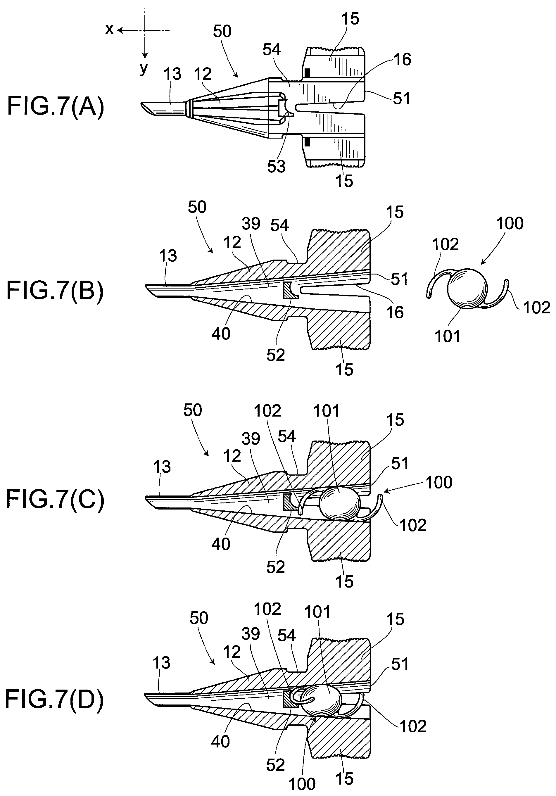
FIGS. 7(A), 7(B), 7(C) and 7 (D) are cross-sectional views of the cartridge used for explanation of how the intraocular lens is installed in the cartridge according to a second embodiment.
FIG. 8 is a perspective view showing the whole structure of the intraocular lens insertion device with the casing according to a third embodiment.
FIG. 9 is a perspective view showing the structure of the intraocular lens insertion device according to the third embodiment.
FIG. 10 is an exploded perspective view showing the structures of the casing and a cover body.
FIG. 11 is a perspective view showing the intraocular lens insertion device placed onto the casing according to the third embodiment.
FIGS. 12(A) and 12(B) are front and side views of the intraocular lens.
FIG. 13 is a front view illustrating how the intraocular lens is inserted into the eye using the intraocular lens insertion device.
BEST MODE FOR CARRYING OUT THE INVENTION
Preferred embodiments of the present invention are described hereinafter with reference to the drawings.
First Embodiment
(1) Basic Structure of Intraocular Lens Insertion Device
In FIG. 1, reference numeral 1 indicates an intraocular lens insertion device as a whole. The intraocular lens insertion device 1 comprises a cartridge 2 and an insertion device body 3 having a plunger 4. The cartridge 2 is attached to an attaching portion 3a of the insertion device body 3. Further, the intraocular lens insertion device 1 has an intraocular lens 100 installed in the cartridge 2, and is structured so as to be able to discharge the intraocular lens 100 from the tip end of the cartridge 2 into an eye by pushing out the intraocular lens 100 in the lens-advancing direction x (i.e., the direction of an arrow x, or an anterior direction in the lens-advancing axis A) using the plunger 4.
(2) Structure of Cartridge
The cartridge 2 attached to the insertion device body 3 as referred to above is described further below. As shown in FIG. 2(A), the cartridge 2, serving as a cylindrical or tubular insertion portion, comprises a cartridge body 14 composed of a lens insertion opening 10, a lens placement portion 11, a transition portion 12 and a nozzle 13 in sequence, along the lens-advancing axis A; and wings 15, 15 extending from both side faces of the cartridge body 14 along the lateral direction y perpendicular to the lens-advancing direction x.
The lens insertion opening 10 is provided with an insertion groove 16 formed on upper and lower surfaces by being cut out in the lens-advancing direction x. The lens placement portion 11 is provided anterior to the lens insertion opening 10 with respect to the lens-advancing axis A, and the transition portion 12 is provided anterior to the lens placement portion 11 with respect to the lens-advancing axis A. An inner wall of the transition portion 12 is formed in the shape of a mortar gradually tapering toward the tip end thereof, and the tip end of the transition portion 12 is communicated with the nozzle 13.
In this way, the cartridge body 14 is formed such that the intraocular lens 100 can be moved from the lens placement portion 11 through the transition portion 12 to the nozzle 13 in sequence by being pushed with the plunger 4 in the lens-advancing direction x. Also, the cartridge body 14 is formed so as to be able to discharge the intraocular lens pushed by the plunger 4 into the eye from a discharge port 13a of the nozzle 13. Here, the nozzle 13 is contoured so that it can be inserted into an incision (not shown).
In addition to the above-mentioned basic structure, the cartridge 2 of the present invention is provided with a protrusion insertion hole 20 formed so as to penetrate the thickness thereof in the vicinity of the lens placement portion 11 toward the vertical direction z perpendicular to both the lens-advancing direction x and the lateral direction y, as illustrated in FIGS. 2(A) and 2(B). In the case of the present embodiment, the protrusion insertion hole 20 is, as shown in FIG. 2(A), shifted toward one side relative to the lens-advancing axis A (in this case, downward) and is formed so as to allow a hole region thereof to cross only a part of a transition space in which the intraocular lens 100 moves.
Furthermore, the cartridge 2 is formed so as to be detachable from a casing 22 on which a protrusion 21 is vertically provided so that the protrusion 21 may be inserted into the protrusion insertion hole 20 by attaching the cartridge 2 to the casing. When the cartridge 2 is attached to the casing 22 and thus the protrusion 21 is inserted into the protrusion insertion hole 20, the protrusion 21 is allowed to pass through a part of the transition space in the cartridge 2 so that the tip end of the protrusion 21 is exposed to the outside.
Here, as shown in FIGS. 5(A), 5(B) and 5(C), the casing 22 includes a casing main body 23 to which the cartridge 2 is attached, and the casing main body 23 is provided with fixing claws 24, 24 for fixedly attaching the cartridge 2 to the casing main body 23 and the said protrusion 21 that is to be inserted into the protrusion insertion hole 20 at the time of the attachment of the cartridge 2.
The casing main body 23 is integrally formed of a synthetic resin material such as a plastic material, and comprises a tip-side holding portion 25 holding the transition portion 12 and nozzle 13 of the cartridge 2; and an insertion-side holding portion 26 holding the lens insertion opening 10, lens placement portion 11 and wings 15, 15 of the cartridge 2.
According to the present embodiment, the tip-side holding portion 25 includes a base plate 27 having a bell shape as a whole such that its side faces are slightly concavely curved toward the inside at their central portions, and a wall portion 28 vertically provided along the outer fringe of the base plate 27. Thus, the tip-side holding portion 25 is formed such that the side faces of the wall portion 28 are also slightly concavely curved toward the inside at their central portions, corresponding to the contour of the base plate 27, so that it may be easily held between user's thumb and index finger.
The tip-side holding portion 25 includes a cutout portion 30 provided at a wall portion 29 on a proximal portion thereof adjacent to the insertion-side holding portion 26. The cutout portion 30 is formed by being cut out in a concavely curved manner, corresponding to the contour of the transition portion 12 of the cartridge 2, thereby enabling the transition portion 12 of the cartridge 2 to be placed on the cutout portion 30.
Further, the tip-side holding portion 25 includes an inner wall portion 31 spaced a distance away from the wall portion 29 on the proximal portion, extending toward the lateral direction y. The inner wall portion 31 is cut out in a concavely curved manner, corresponding to the contour of the transition portion 12 of the cartridge 2, thereby enabling the transition portion 12 of the cartridge 2 to be placed on a cutout portion 32 thereof as well.
Furthermore, the tip-side holding portion 25 includes the two fixing claws 24, 24 opposed to each other, at given positions on the base plate 27 between the wall portion 29 on the proximal side and the inner wall portion 31. Here, the two fixing claws 24, 24 have elastic retention capacity as a result of selecting a synthetic resin material as a material, thereby expanding the fixing claws 24, 24 toward the lateral direction y by an external force applied at the time when the cartridge 2 is placed on the casing 22 and returning the fixing claws 24, 24 to an original state at the time when the external force is no longer applied.
The fixing claws 24, 24 are each provided, at their tip end, with an engaging claw 24a folded back toward the upper face side of the cartridge 2, so that the cartridge 2 may be fitted and held in the casing 22 through the two fixing claws 24, 24 of the tip-side holding portion 25.
On the other hand, the insertion-side holding portion 26 comprises a base plate 35 formed by cutting a rectangular plate in a letter U shape, and a wall portion 36 vertically provided at both side faces of the base plate 35. The insertion-side holding portion 26 is configured to hold the cartridge 2 due to the wings 15 of the cartridge 2 abutting onto the upper faces of the wall portions 36 when the cartridge 2 is fitted in the fixing claws 24 of the tip-side holding portion 25 (See FIG. 4).
In addition to the above-mentioned structure, the casing 22 of the present invention is provided with the protrusion 21 vertically extending from the base plate 35 of the insertion-side holding portion 26. The protrusion 21 is formed so that it may be able to be inserted into the protrusion insertion hole 20 of the cartridge 2 when the cartridge 2 is installed in the casing 22 through the fixing claws 24, 24 of the tip-side holding portion 25.
In practice, the protrusion 21, serving as a folding means, is strip-shaped and formed to have a given thickness, corresponding to the shape of the opening of the protrusion insertion hole 20 of the cartridge 2, and is vertically provided on the base plate 35 of the insertion-side holding portion 26 so as to be extended in the vertical direction z. With the cartridge 2 being installed on such casing 22, the intraocular lens 100 can be inserted from the lens insertion opening 10 of the cartridge 2.
Then, as shown in FIG. 6(A), the optical portion 101 of the intraocular lens 100 is folded in two with supporting portions 102, 102 extended outward. With that posture, the optical portion 101 is grasped with tweezers (not shown), and then, as shown in FIG. 6(B), the intraocular lens is inserted into the lens insertion opening 10 while it is arranged so as to allow the tip end of one of the supporting portions 102 to abut onto the protrusion 21. Here, for sake of simplicity, the casing main body 23 is not shown but only the protrusion 21 is shown in FIGS. 6(A) to 6(C).
Then, the cartridge 2 allows the distal end of the supporting portion 102 of the intraocular lens 100 to abut onto the protrusion 21 that is exposed within the transition space 39. With the tip actually being abutted onto the protrusion 21, the intraocular lens 100 is inserted up to the lens placement portion 11 by the tweezers. In this way, as shown in FIG. 6(C), the cartridge 2 allows the distal end of the supporting portion 102 to be folded back by the protrusion 21 in the opposite direction against the lens-advancing direction x (hereinafter, this is called backward direction).
Thus, the cartridge 2 is able to place the intraocular lens 100 on the lens placement portion 11 with the supporting portion 102 being folded in a substantially U-shape by the protrusion 21.
Moreover, the cartridge 2 is formed such that the optical portion 101 of the intraocular lens 100 abuts on the protrusion 21 that is inserted through the protrusion insertion hole 20 and is exposed to the transition space 39, so that the protrusion 21 receives the optical portion 101, thereby precisely positioning the intraocular lens 100 on the lens placement portion 11.
After that, the cartridge 2 is removed from the casing 22 and thus the protrusion 21 is allowed to disengage from the protrusion insertion hole 20. However, the cartridge 2 can keep the distal end of the supporting portion 102 folded back toward the optical portion 101 by allowing the supporting portion 10 of the intraocular lens 100, which had been abutted onto the protrusion 21 until then, to abut onto an inner wall 40 of the transition space 39. In such state, the cartridge 2 is capable of being attached to the attaching portion 3a of the insertion device body 3. Thus, the intraocular lens insertion device 1 allows the intraocular lens 100 to be pushed out by the plunger 4 toward the lens-advancing direction x with the supporting portion 102 being folded back, thus enabling the intraocular lens 100 to be released into an eye from the nozzle 13 provided on the tip end of the cartridge 2.
At this time, the intraocular lens insertion device 1 of the present invention allows the curved portion of the folded supporting portion 102, which has become U-shaped and less likely to move freely, to be exposed from the discharge port 13a of the nozzle 13, and then allows the optical portion 101 to be released from the discharge port 13a thereof by pushing out the intraocular lens 100 by the plunger 4, thereby preventing only the distal end of the supporting portion 102 from being released and moved freely in the process of releasing the intraocular lens 100 into the eye from the tip end of the cartridge 2.
3. Behavior and Effects
According to the above-mentioned structure, the cartridge 2 is installed in the casing 22, thereby allowing the protrusion 21 provided on the casing 22 to be inserted into the protrusion insertion hole 20 so that the protrusion 21 can be exposed to the transition space 39.
A user may insert the intraocular lens 100 from the lens insertion opening 10 with the cartridge 2 being installed in the casing 22, and place the intraocular lens 100 on the lens placement portion 11. At this time, the user can pinch the wall portion 28 of the casing 22 much larger in size than the wings 15, 15 without directly pinching the wings 15, 15 of the cartridge 2, thereby enabling the cartridge 2 to be easily stabilized. Thus, the user can place the intraocular lens 100 on the lens placement portion 11 more easily than by the conventional ones.
Further, the user can hold the cartridge 2 in a stable condition by pinching the wall portion 28 of the casing 22, thus enabling the user to easily fill a viscoelastic material such as a hyaluronic acid preparation for ophthalmic application into the inside of the cartridge 2.
Furthermore, according to the cartridge 2, when the intraocular lens 100 is gradually inserted from the lens insertion opening 10 in order to place the intraocular lens 100 on the lens placement portion 11, the distal end of the supporting portion 102 of the intraocular lens 100 is allowed to abut on the protrusion 21, and thus the distal end of the supporting portion 102 in the lens-advancing direction x can be folded backward.
Particularly, according to the present embodiment, since the protrusion 21 is not exposed all through the transition space 39, but is only exposed in a part thereof at one side in the lens-advancing axis A, it is possible to allow only the distal end of the supporting portion 102 to abut on the protrusion 21, thereby ensuring an intermediate portion between the distal end of the supporting portion 102 and the proximal portion thereof to be folded in a U-shape.
According to the intraocular lens insertion device 1, therefore, the supporting portion 102 of the intraocular lens placed on the lens advancing side with respect to the lens-advancing direction x is pressed against the protrusion 21 to thereby be folded backward, thus enabling the curved portion of the folded supporting portion 102, which has become U-shaped and less likely to move freely, to be first released when releasing the intraocular lens 100 from the nozzle 13. Thus, the intraocular lens 100 can be more easily inserted into an eye with the same kept in a more stable condition than by the conventional ones.
Moreover, the intraocular lens insertion device 1 is detachably provided with the protrusion 21, thereby preventing the protrusion 21 from blocking the movement of the intraocular lens 100 when inserting the intraocular lens 100 into an eye.
Additionally, according to the present embodiment, the protrusion insertion hole 20 of the cartridge 2 is drilled at the top face of the lens placement portion 11 so that the tip of the protrusion 21 of the casing 22 is exposed from the top face of the lens placement portion 11, and thus a user can visually confirm the position of the protrusion 21 in a moment. Accordingly, it is possible to ensure the distal end of the supporting portion 102 to be properly placed on the side of the protrusion 21 so that the supporting portion 102 may be pressed to the protrusion 21 and folded when the intraocular lens 100 is placed on the lens placement portion 11.
Also, according to the present embodiment, the protrusion 21 is provided on the casing 22, and thus even thin and short protrusion 21 can be inserted into and removed from the protrusion insertion hole 20 of the cartridge 2 by just attaching and detaching the casing 22 to and from the cartridge 2.
Besides, the cartridge 2 is installed in the casing 22, and thus the nozzle 13, the transition portion 12 and the like can be protected against an external force owing to the casing 22. In addition, the cartridge 2 can be placed on a pedestal with the casing 22 installed, thus preventing the nozzle 13, the transition portion 12 and the like from directly contacting the pedestal. Accordingly, the cartridge 2 can be always kept clean.
Second Embodiment
FIGS. 7(A) to 7(D), which are given the same reference numerals as corresponding parts in FIGS. 6(A) to 6(C), shows a cartridge according to a second embodiment. A cartridge 50 is different from that of the foregoing first embodiment in that the optical portion 101 is inserted into a lens insertion opening 51 without being folded in half.
In practice, as shown in FIGS. 7(A) and 7(B), the cartridge 50 is formed so as to be able to be installed in the casing not shown in the drawings. When it is installed in the casing, a protrusion 52 provided on the casing is allowed to be inserted into a protrusion insertion hole 53. In the meantime, for sake of simplicity, the casing is not shown in FIGS. 7(A) to 7(D) but only the protrusion 52 is shown therein.
In practice, the protrusion insertion hole 53 is drilled so as to penetrate the thickness in the vicinity of the lens placement portion 54 toward the bottom-to-top direction (toward a viewer seeing the drawing) perpendicular to both the lens-advancing direction x and the lateral direction y. In this embodiment, the protrusion insertion hole 20 is drilled in the substantial center of the lens placement portion 54 so as to cross the lens-advancing axis A, and thus an hole region is formed in the middle of the transition space in which the intraocular lens 100 moves.
Thus, when the protrusion 52 is inserted into protrusion insertion hole 53 by installing the cartridge 50 in the casing, the protrusion 52 passes through the middle of the transition space 39 and the tip of the protrusion 52 can be exposed to the outside.
In that state, the intraocular lens 100 is pinched with a tweezers (not shown) with the supporting portions 102, 102 extending outwardly and the optical portion 101 unfolded, and then it may be inserted into the lens insertion opening 51 of the cartridge 50, with the tip of one supporting portion 102 being the leading end, as illustrated in FIG. 7(C).
At this time, the cartridge 50 allows the distal end of the supporting portion 102 of the intraocular lens 100 to abut on the protrusion 21 exposed inside the transition space 39. In that state, the intraocular lens 100 is inserted up to the lens placement portion 54 by the tweezers. In this way, as shown in FIG. 7(D), the cartridge 50 allows the distal end of the supporting portion 102 to be folded back along a curved surface of the protrusion 52 in the opposite direction relative to the lens-advancing direction x. Thus, the cartridge 50 enables the intraocular lens 100 to be placed on the lens placement portion 54 with the supporting portion 102 being folded in a U-shape by the protrusion 52.
In this embodiment, the surface of the protrusion 52 on which the supporting portion 102 of the intraocular lens 100 abuts is curved toward a given direction, thereby ensuring the supporting portion 102 of the intraocular lens 100 to be bent in a desired direction along the curved surface.
After that, like in the above-mentioned first embodiment, the cartridge 50 is removed from the casing and thus the protrusion 52 disengages from the protrusion insertion hole 53. The cartridge 50, however, is capable of keeping the distal end of the supporting portion 102 folded due to the supporting portion 102 of the intraocular lens 100, which had been abutted on the protrusion 52 until then, to then abut onto the inner wall 40 in the transition space 39. In such state, the cartridge 50 is capable of being attached to the attaching portion of the insertion device body not shown. Thus, the intraocular lens insertion device allows the intraocular lens 100 to be pushed out by the plunger 4 in the lens-advancing direction x with the supporting portion 102 being folded back, thus enabling the intraocular lens 100 to be released into an eye from the nozzle 13 provided on the tip end of the cartridge 2.
Third Embodiment
In FIG. 8, numeral 60 denotes an assembly of an intraocular lens insertion device and a casing according to a third embodiment. The assembly 60 of an intraocular lens insertion device and a casing comprises an intraocular lens insertion device 61, a casing 62 on which the intraocular lens insertion device 61 is detachably installed, and a cover body 63 which is detachably attached to the casing 62 on which the intraocular lens insertion device 61 is installed to cover the intraocular lens insertion device 61.
At first, the intraocular lens insertion device 61 is described hereinbelow. The intraocular lens insertion device 61 is of a preset-type in which the intraocular lens 100 is set in advance, unlike in the foregoing first and second embodiments.
As shown in FIG. 9, the intraocular lens insertion device 61 comprises a main body 66, a slider 67, a plunger 68 and a locking mechanism, and this main body 66 comprises a cylindrical proximal member 70 and a tapered distal member 71.
In this case, a lens placement portion (not shown) made of a plate member is provided in the distal portion of the proximal member 70 on the lens advancing side with respect to the lens-advancing axis A so that the intraocular lens 100 may be placed on the lens placement portion. Further, the tapered distal member 71 is connected integrally with the proximal member 70 so that the intraocular lens 100 placed on the lens placement portion of the proximal member 70 may be placed in the inside of the tapered distal member 71.
The slider 67 and the plunger 68 are provided so as to be movable back-and-forth in the main body 66. The locking mechanism 69 can limit the forward movement of the plunger 68. The locking mechanism 69 is unlocked by moving the slider 67 forward, thereby allowing the plunger 68 to be movable forward.
The intraocular lens insertion device 61 thus structured allows the intraocular lens 100 to be pushed by the slider 67 so that it is properly folded in a predetermined shape at first, and then allows the intraocular lens 100 to be inserted into an eye by folding the intraocular lens 100 even smaller by continuously pushing the intraocular lens 100 by the plunger 68. Accordingly, the intraocular lens insertion device 61 is structured such that the locking mechanism 69 thereof ensures that the intraocular lens 100 is prevented from being pushed out by the plunger 68 prior to being pushed out by the slider 67, and thus the intraocular lens 100 placed in the main body 66 is folded as it is moved forward in two steps by the slider 67 and then by the plunger.
These matters have already been disclosed by the present applicant. For details relating to the matters, one may refer to the description in Best Mode for Carrying Out the Invention in PCT/JP2008/59995, for example.
In this case, the cylindrical insertion portion according to claim 1 comprises the lens placement portion and the tapered distal member 71, and in the tapered distal member 71, a protrusion insertion hole 73 is drilled so as to penetrate the thickness of the tapered distal member 71 toward the vertical direction z perpendicular to both the lens-advancing direction x and the lateral direction y. According to this embodiment, the protrusion insertion hole 73 is drilled in the approximate center of the lens placement portion 54 so as to cross the lens-advancing axis A, and a hole region is formed in the middle of the transition space in which the intraocular lens 100 moves.
The intraocular lens insertion device 61 is capable of being removably attached to the casing 62 which is separate from the intraocular lens insertion device 61 and is formed from e.g., a synthetic resin material into a one-piece structure. As shown in FIG. 10, a U-shaped wall portion 76 is vertically provided on a base plate 75 of the casing 63, in a manner surrounding the intraocular lens insertion device 61, while a protrusion 80 is vertically provided on a given position of the base plate 75.
The protrusion 80 has the same structure as that of the foregoing second embodiment so that it may be, as shown in FIG. 11, inserted into the protrusion insertion hole 73 of the intraocular lens insertion device 61 by installing the intraocular lens insertion device 61 in the casing 62. In this way, in the intraocular lens insertion device 61, the protrusion 80 of the casing 62 can be arranged in the center region of the transition space of the tapered distal member 71.
Also, as shown in FIG. 10, the wall portion 76 of the casing 62 is formed, on its both sides, with a stepped portion 81 whose height from the base plate 75 is comparatively low. As shown in FIG. 11, when the intraocular lens insertion device 61 is installed, the slider 67 of the intraocular lens insertion device 61 is capable of being located on the stepped portion 81.
At this time, there is a given distance between an abutting surface 82 of the wall portion 76 and the slider 67 of the intraocular lens insertion device 61.
Thus, the intraocular lens insertion device 61 can move the intraocular lens 100 installed inside the tapered distal member 71 toward the lens-advancing direction x up to a given position, by allowing the slider 67 in the lens-advancing direction x until it abuts on the abutting surface 82 of the wall portion 76 of the casing 62.
In this way, like in the foregoing second embodiment, the intraocular lens 100 is allowed to have its supporting portion 102 abutted on the protrusion 80 so as to have the tip end of the supporting portion 102 folded back along a curved surface of the protrusion 80 in the backward direction opposed to the lens-advancing direction x. Thus, the intraocular lens insertion device 61 is capable of placing the intraocular lens 100 on the lens placement portion (not shown) with the supporting portion 102 folded in a substantially U-shape by the protrusion 80.
Also, the intraocular lens insertion device 61 is detached from the casing 62 with the above arrangement being retained, and then the intraocular lens 100 is pushed out by the plunger 68 in the lens-advancing direction x with the supporting portion 102 folded back, thereby allowing the intraocular lens 100 to be released from a nozzle 85 of the tapered distal member 71.
In the meantime, as shown in FIG. 10, fitting holes 86 are drilled on the top surface of the wall portion 76 of the casing 62 so that fitting protrusions 87 provided on the lower surface of the cover body 63 may be fitted into the fitting holes 86, thereby allowing the cover body 63 to be attached to the casing 62.
In practice, the contour of the lower surface of the cover body 63 is formed corresponding to that of the top surface of the wall portion 76 of the casing 62, and thus it includes a stepped abutting portion 88 formed corresponding to the shape of the stepped portion 81 of the wall portion 76.
Accordingly, as shown in FIG. 8, when the cover body 63 is attached to the casing 62 on which the intraocular lens insertion device 61 is installed, the stepped abutting portion 88 is fitted in a gap formed between the abutting surface 82 of the wall portion 76 of the casing 62 and the slider 67 of the intraocular lens insertion device 61, thereby preventing the slider 67 from sliding.
Additionally, as shown in FIG. 10, the cover body 63 may have, for example, two positioning protrusions 90, 91 on the lower surface thereof so that the positioning protrusions 90, 91 may be inserted into positioning holes 92, 93 drilled in the tapered distal member 71 of the intraocular lens insertion device 61 (see FIG. 9). Accordingly, when the cover body 63 is attached to the casing 62, the positioning protrusions 90, 91 of the cover body 63 are inserted into these positioning holes 92, 93 respectively, thereby allowing the two supporting portions 102, 102 of the intraocular lens 100 to be properly positioned by allowing them to abut on the positioning protrusions 90, 91. Here, it is to be noted that the intraocular lens insertion device 61 allows a viscoelastic material such as a hyaluronic acid preparation for ophthalmic application to be filled thereinside through one positioning hole 91 by a syringe or the like not shown in the drawings.
From the above-mentioned structure, the intraocular lens insertion device 61 enables the supporting portion 102 of the intraocular lens 100 arranged on the lens-advancing side with respect to the lens-advancing direction x to be bent by the protrusion 80 in the backward direction, thus enabling the curved portion of the supporting portion 102, which has become U-shaped and hardly movable, to be released first when releasing the intraocular lens 100 from the tapered distal member 71, thereby enabling the intraocular lens 100 to be inserted into an eye more easily and stably compared to by the conventional ones.
Other Embodiments
The present invention is not limited to the foregoing embodiments and various modifications are possible within the scope of the gist of the present invention. For example, the protrusion may be formed in a circular or various other shapes. Further, the present invention is also applicable to other intraocular lens which has only one supporting portion, or three, four or more supporting portions provided on the optical portion.
Whilst the supporting portion 102 is folded in a U-shape by the protrusions 21, 52, 80 in the foregoing embodiments, the present invention is not limited thereto, but the supporting portion 102 may be folded in V-, C-, L- or various other shapes by the protrusions 21, 52, 80.
Moreover, whilst the protrusions 21, 52, 80 extending in the vertical direction z are proposed in the foregoing embodiments, the present invention is not limited thereto. Any other protrusions extending in the lateral direction y, oblique direction, or various other directions may be possible, as long as the distal end of the supporting portion 102 of the intraocular lens 100 can be folded in the backward direction which is opposed to the lens-advancing direction x. In these cases, a protrusion insertion hole may be drilled in the cartridge 2, 50 and the tapered distal member 71, corresponding to the extending direction of the protrusion.
Additionally, whilst the protrusions 21, 80 are provided on the casings 22, 62 respectively in the foregoing embodiments, the present invention is not limited thereto, but various other configurations are applicable, such that only the protrusion may be detachably provided, or the protrusion may be provided on the cartridge or tapered distal member itself, and then moved by a slide mechanism.
In addition, whilst the protrusion insertion hole 20 is provided in the vicinity of the lens placement portion 11 in the foregoing embodiments, the present invention is not limited to this. The protrusion 21 may be provided on the lens insertion opening 10, transition portion 12, or various other portions, as long as the tip end of the supporting portion 102 of the intraocular lens 100 can be folded in the backward direction as opposed to the lens-advancing direction x when the intraocular lens is released from the nozzle 13.
In addition to the foregoing, whilst the protrusion insertion hole 20 is drilled through between the top surface and the lower surface of the lens placement portion 11 and the tip of the protrusion 21 is exposed from the top surface of the lens placement portion 11 in the foregoing embodiments, the present invention is not limited thereto. The protrusion insertion hole 20 may be drilled through only the lower surface of the lens placement portion 11 so that the tip of the protrusion 21 may not be exposed from the top surface of the lens placement portion 11.
* * * * *
D00000
D00001
D00002
D00003
D00004
D00005
D00006
D00007
D00008
XML
uspto.report is an independent third-party trademark research tool that is not affiliated, endorsed, or sponsored by the United States Patent and Trademark Office (USPTO) or any other governmental organization. The information provided by uspto.report is based on publicly available data at the time of writing and is intended for informational purposes only.
While we strive to provide accurate and up-to-date information, we do not guarantee the accuracy, completeness, reliability, or suitability of the information displayed on this site. The use of this site is at your own risk. Any reliance you place on such information is therefore strictly at your own risk.
All official trademark data, including owner information, should be verified by visiting the official USPTO website at www.uspto.gov. This site is not intended to replace professional legal advice and should not be used as a substitute for consulting with a legal professional who is knowledgeable about trademark law.