Devices and methods for tissue sealing and mechanical clipping
Allen, IV Dec
U.S. patent number 10,517,665 [Application Number 15/627,571] was granted by the patent office on 2019-12-31 for devices and methods for tissue sealing and mechanical clipping. This patent grant is currently assigned to COVIDIEN LP. The grantee listed for this patent is COVIDIEN LP. Invention is credited to James D. Allen, IV.


| United States Patent | 10,517,665 |
| Allen, IV | December 31, 2019 |
Devices and methods for tissue sealing and mechanical clipping
Abstract
A tissue clip including an electrode assembly having first and second electrodes with an insulator disposed therebetween. The electrodes are configured to connect to opposite potentials of an energy source. The electrodes and insulator are deformable to shape the tissue clip to include upper and lower legs with a twisted central portion defined therebetween. The upper leg includes an outer facing portion having one end of the first electrode removably coupled to a first jaw of a forceps and an inner facing portion including an end of the second electrode configured to grasp tissue. The lower leg includes an outer facing portion having an opposite end of the second electrode removably coupled to a second jaw and an inner facing portion that includes the opposite end of the first electrode and is configured to grasp tissue.
| Inventors: | Allen, IV; James D. (Broomfield, CO) | ||||||||||
|---|---|---|---|---|---|---|---|---|---|---|---|
| Applicant: |
|
||||||||||
| Assignee: | COVIDIEN LP (Mansfield,
MA) |
||||||||||
| Family ID: | 60941631 | ||||||||||
| Appl. No.: | 15/627,571 | ||||||||||
| Filed: | June 20, 2017 |
Prior Publication Data
| Document Identifier | Publication Date | |
|---|---|---|
| US 20180014876 A1 | Jan 18, 2018 | |
Related U.S. Patent Documents
| Application Number | Filing Date | Patent Number | Issue Date | ||
|---|---|---|---|---|---|
| 62362107 | Jul 14, 2016 | ||||
| Current U.S. Class: | 1/1 |
| Current CPC Class: | A61B 17/122 (20130101); A61B 17/1285 (20130101); A61B 18/1445 (20130101); A61B 17/083 (20130101); A61B 17/10 (20130101); A61B 2017/00946 (20130101); A61B 2017/00929 (20130101); A61B 2018/00184 (20130101); A61B 2018/0063 (20130101); A61B 2018/1465 (20130101) |
| Current International Class: | A61B 17/00 (20060101); A61B 17/122 (20060101); A61B 18/14 (20060101); A61B 17/128 (20060101); A61B 17/10 (20060101); A61B 17/08 (20060101); A61B 18/00 (20060101) |
References Cited [Referenced By]
U.S. Patent Documents
| D249549 | September 1978 | Pike |
| D263020 | February 1982 | Rau, III |
| D295893 | May 1988 | Sharkany et al. |
| D295894 | May 1988 | Sharkany et al. |
| D298353 | November 1988 | Manno |
| D299413 | January 1989 | DeCarolis |
| 5201900 | April 1993 | Nardella |
| D343453 | January 1994 | Noda |
| D348930 | July 1994 | Olson |
| D349341 | August 1994 | Lichtman et al. |
| D354564 | January 1995 | Medema |
| D358887 | May 1995 | Feinberg |
| D384413 | September 1997 | Zlock et al. |
| H1745 | August 1998 | Paraschac |
| 5833700 | November 1998 | Fogelberg |
| D402028 | December 1998 | Grimm et al. |
| D408018 | April 1999 | McNaughton |
| D416089 | November 1999 | Barton et al. |
| D424694 | May 2000 | Tetzlaff et al. |
| D425201 | May 2000 | Tetzlaff et al. |
| H1904 | October 2000 | Yates et al. |
| D449886 | October 2001 | Tetzlaff et al. |
| D453923 | February 2002 | Olson |
| D454951 | March 2002 | Bon |
| D457958 | May 2002 | Dycus et al. |
| D457959 | May 2002 | Tetzlaff et al. |
| H2037 | July 2002 | Yates et al. |
| D465281 | November 2002 | Lang |
| D466209 | November 2002 | Bon |
| D493888 | August 2004 | Reschke |
| D496997 | October 2004 | Dycus et al. |
| D499181 | November 2004 | Dycus et al. |
| D502994 | March 2005 | Blake, III |
| D509297 | September 2005 | Wells |
| D525361 | July 2006 | Hushka |
| D531311 | October 2006 | Guerra et al. |
| D533274 | December 2006 | Visconti et al. |
| D533942 | December 2006 | Kerr et al. |
| D535027 | January 2007 | James et al. |
| D538932 | March 2007 | Malik |
| D541418 | April 2007 | Schechter et al. |
| D541611 | May 2007 | Aglassinger |
| D541938 | May 2007 | Kerr et al. |
| D545432 | June 2007 | Watanabe |
| D547154 | July 2007 | Lee |
| D564662 | March 2008 | Moses et al. |
| D567943 | April 2008 | Moses et al. |
| D575395 | August 2008 | Hushka |
| D575401 | August 2008 | Hixson et al. |
| D582038 | December 2008 | Swoyer et al. |
| D617900 | June 2010 | Kingsley et al. |
| D617901 | June 2010 | Unger et al. |
| D617902 | June 2010 | Twomey et al. |
| D617903 | June 2010 | Unger et al. |
| D618798 | June 2010 | Olson et al. |
| D621503 | August 2010 | Otten et al. |
| D627462 | November 2010 | Kingsley |
| D628289 | November 2010 | Romero |
| D628290 | November 2010 | Romero |
| D630324 | January 2011 | Reschke |
| D649249 | November 2011 | Guerra |
| D649643 | November 2011 | Allen, IV et al. |
| D661394 | June 2012 | Romero et al. |
| D670808 | November 2012 | Moua et al. |
| D680220 | April 2013 | Rachlin |
| 9084608 | July 2015 | Larson et al. |
| 9211657 | December 2015 | Ackley et al. |
| 9750522 | September 2017 | Scheib |
| 2004/0087987 | May 2004 | Rosenberg |
| 2012/0059394 | March 2012 | Brenner |
| 2013/0018364 | January 2013 | Chernov |
| 2014/0221995 | August 2014 | Guerra et al. |
| 2014/0221999 | August 2014 | Cunningham et al. |
| 2014/0228842 | August 2014 | Dycus et al. |
| 2014/0230243 | August 2014 | Roy et al. |
| 2014/0236149 | August 2014 | Kharin et al. |
| 2014/0243811 | August 2014 | Reschke et al. |
| 2014/0243824 | August 2014 | Gilbert |
| 2014/0249528 | September 2014 | Hixson et al. |
| 2014/0250686 | September 2014 | Hempstead et al. |
| 2014/0257274 | September 2014 | McCullough, Jr. et al. |
| 2014/0257283 | September 2014 | Johnson et al. |
| 2014/0257284 | September 2014 | Artale |
| 2014/0257285 | September 2014 | Moua |
| 2014/0276803 | September 2014 | Hart |
| 2014/0284313 | September 2014 | Allen, IV et al. |
| 2014/0288549 | September 2014 | McKenna et al. |
| 2014/0288553 | September 2014 | Johnson et al. |
| 2014/0330308 | November 2014 | Hart et al. |
| 2014/0336635 | November 2014 | Hart et al. |
| 2014/0353188 | December 2014 | Reschke et al. |
| 2015/0018816 | January 2015 | Latimer |
| 2015/0025528 | January 2015 | Arts |
| 2015/0032106 | January 2015 | Rachlin |
| 2015/0051598 | February 2015 | Orszulak et al. |
| 2015/0051640 | February 2015 | Twomey et al. |
| 2015/0066026 | March 2015 | Hart et al. |
| 2015/0080880 | March 2015 | Sartor et al. |
| 2015/0080889 | March 2015 | Cunningham et al. |
| 2015/0082928 | March 2015 | Kappus et al. |
| 2015/0088122 | March 2015 | Jensen |
| 2015/0088126 | March 2015 | Duffin et al. |
| 2015/0088128 | March 2015 | Couture |
| 2015/0094714 | April 2015 | Lee et al. |
| 2016/0038226 | February 2016 | Brandt et al. |
| 2016/0143687 | May 2016 | Hart et al. |
| 201299462 | Sep 2009 | CN | |||
| 2415263 | Oct 1975 | DE | |||
| 02514501 | Oct 1976 | DE | |||
| 2627679 | Jan 1977 | DE | |||
| 03423356 | Jun 1986 | DE | |||
| 03612646 | Apr 1987 | DE | |||
| 3627221 | Feb 1988 | DE | |||
| 8712328 | Feb 1988 | DE | |||
| 04303882 | Feb 1995 | DE | |||
| 04403252 | Aug 1995 | DE | |||
| 19515914 | Jul 1996 | DE | |||
| 19506363 | Aug 1996 | DE | |||
| 29616210 | Nov 1996 | DE | |||
| 19608716 | Apr 1997 | DE | |||
| 19751106 | May 1998 | DE | |||
| 19751108 | May 1999 | DE | |||
| 19946527 | Jul 2001 | DE | |||
| 20121161 | Apr 2002 | DE | |||
| 10045375 | Oct 2002 | DE | |||
| 202007009165 | Aug 2007 | DE | |||
| 202007009317 | Aug 2007 | DE | |||
| 202007009318 | Aug 2007 | DE | |||
| 10031773 | Nov 2007 | DE | |||
| 202007016233 | Jan 2008 | DE | |||
| 19738457 | Jan 2009 | DE | |||
| 102004026179 | Jan 2009 | DE | |||
| 102008018406 | Jul 2009 | DE | |||
| 1281878 | Feb 2003 | EP | |||
| 1159926 | Mar 2003 | EP | |||
| 2489320 | Aug 2012 | EP | |||
| 61-501068 | Sep 1984 | JP | |||
| 10-24051 | Jan 1989 | JP | |||
| 11-47150 | Jun 1989 | JP | |||
| 6-502328 | Mar 1992 | JP | |||
| 5-5106 | Jan 1993 | JP | |||
| 05-40112 | Feb 1993 | JP | |||
| 0006030945 | Feb 1994 | JP | |||
| 6-121797 | May 1994 | JP | |||
| 6-285078 | Oct 1994 | JP | |||
| 6-511401 | Dec 1994 | JP | |||
| 06343644 | Dec 1994 | JP | |||
| 07265328 | Oct 1995 | JP | |||
| 8-56955 | May 1996 | JP | |||
| 08252263 | Oct 1996 | JP | |||
| 8-289895 | Nov 1996 | JP | |||
| 8-317934 | Dec 1996 | JP | |||
| 8-317936 | Dec 1996 | JP | |||
| 9-10223 | Jan 1997 | JP | |||
| 09000538 | Jan 1997 | JP | |||
| 9-122138 | May 1997 | JP | |||
| 0010000195 | Jan 1998 | JP | |||
| 10-155798 | Jun 1998 | JP | |||
| 11-47149 | Feb 1999 | JP | |||
| 11-070124 | Mar 1999 | JP | |||
| 11-169381 | Jun 1999 | JP | |||
| 11-192238 | Jul 1999 | JP | |||
| 11244298 | Sep 1999 | JP | |||
| 2000-102545 | Apr 2000 | JP | |||
| 2000-135222 | May 2000 | JP | |||
| 2000342599 | Dec 2000 | JP | |||
| 2000350732 | Dec 2000 | JP | |||
| 2001008944 | Jan 2001 | JP | |||
| 2001-29355 | Feb 2001 | JP | |||
| 2001029356 | Feb 2001 | JP | |||
| 2001-03400 | Apr 2001 | JP | |||
| 2001128990 | May 2001 | JP | |||
| 2001-190564 | Jul 2001 | JP | |||
| 2002-136525 | May 2002 | JP | |||
| 2002-528166 | Sep 2002 | JP | |||
| 2003-116871 | Apr 2003 | JP | |||
| 2003-175052 | Jun 2003 | JP | |||
| 2003245285 | Sep 2003 | JP | |||
| 2004-517668 | Jun 2004 | JP | |||
| 2004-528869 | Sep 2004 | JP | |||
| 2005-152663 | Jun 2005 | JP | |||
| 2005-253789 | Sep 2005 | JP | |||
| 2005312807 | Nov 2005 | JP | |||
| 2006-015078 | Jan 2006 | JP | |||
| 2006-501939 | Jan 2006 | JP | |||
| 2006-095316 | Apr 2006 | JP | |||
| 2008-054926 | Mar 2008 | JP | |||
| 2011125195 | Jun 2011 | JP | |||
| 401367 | Nov 1974 | SU | |||
| 0036986 | Jun 2000 | WO | |||
| 0059392 | Oct 2000 | WO | |||
| 0115614 | Mar 2001 | WO | |||
| 0154604 | Aug 2001 | WO | |||
| 02/45589 | Jun 2002 | WO | |||
| 02080793 | Oct 2002 | WO | |||
| 06/021269 | Mar 2006 | WO | |||
| 05110264 | Apr 2006 | WO | |||
| 08/040483 | Apr 2008 | WO | |||
| 2011/018154 | Feb 2011 | WO | |||
| 2011156257 | Dec 2011 | WO | |||
Other References
|
Michael Choti, "Abdominoperineal Resection with the LigaSure Vessel Sealing System and LigaSure Atlas 20 cm Open Instrument"; Innovations That Work, Jun. 2003. cited by applicant . Chung et al., "Clinical Experience of Sutureless Closed Hemorrhoidectomy with LigaSure" Diseases of the Colon & Rectum vol. 46, No. 1 Jan. 2003. cited by applicant . Tinkcler L.F., "Combined Diathermy and Suction Forceps", Feb. 6, 1967 (Feb. 6, 1967), British Medical Journal Feb. 6, 1976, vol. 1, nr. 5431 p. 361, ISSN: 0007-1447. cited by applicant . Carbonell et al., "Comparison of theGyrus PlasmaKinetic Sealer and the Valleylab LigaSure Device in the Hemostasis of Small, Medium, and Large-Sized Arteries" Carolinas Laparoscopic and Advanced Surgery Program, Carolinas Medical Center,Charlotte,NC; Date: Aug. 2003. cited by applicant . Peterson et al. "Comparison of Healing Process Following Ligation with Sutures and Bipolar Vessel Sealing" Surgical Technology International (2001). cited by applicant . "Electrosurgery: A Historical Overview" Innovations in Electrosurgery; Sales/Product Literature; Dec. 31, 2000. (6 pages). cited by applicant . Johnson et al. "Evaluation of a Bipolar Electrothermal Vessel Sealing Device in Hemorrhoidectomy" Sales/Product Literature; Jan. 2004. (1 page). cited by applicant . E. David Crawford "Evaluation of a New Vessel Sealing Device in Urologic Cancer Surgery" Sales/Product Literature 2000. cited by applicant . Johnson et al. "Evaluation of the LigaSure Vessel Sealing System in Hemorrhoidectormy" American College of Surgeons (ACS) Clinicla Congress Poster (2000). cited by applicant . Muller et al., "Extended Left Hemicolectomy Using the LigaSure Vessel Sealing System" Innovations That Work, Sep. 1999. cited by applicant . Kennedy et al. "High-burst-strength, feedback-controlled bipolar vessel sealing" Surgical Endoscopy (1998) 12: 876-878. cited by applicant . Burdette et al. "In Vivo Probe Measurement Technique for Determining Dielectric Properties At VHF Through Microwave Frequencies", IEEE Transactions on Microwave Theory and Techniques, vol. MTT-28, No. 4, Apr. 1980 pp. 414-427. cited by applicant . Carus et al., "Initial Experience With the LigaSure Vessel Sealing System in Abdominal Surgery" Innovations That Work, Jun. 2002. cited by applicant . Heniford et al. "Initial Results with an Electrothermal Bipolar Vessel Sealer" Surgical Endoscopy (2000) 15:799-801. (4 pages). cited by applicant . Herman et al., "Laparoscopic Intestinal Resection With the LigaSure Vessel Sealing System: A Case Report"; Innovations That Work, Feb. 2002. cited by applicant . Koyle et al., "Laparoscopic Palomo Varicocele Ligation in Children and Adolescents" Pediatric Endosurgery & Innovative Techniques, vol. 6, No. 1, 2002. cited by applicant . W. Scott Helton, "LigaSure Vessel Sealing System: Revolutionary Hemostasis Product for General Surgery"; Sales/Product Literature 1999. cited by applicant . LigaSure Vessel Sealing System, the Seal of Confidence in General, Gynecologic, Urologic, and Laparaoscopic Surgery; Sales/Product Literature; Apr. 2002. cited by applicant . Joseph Ortenberg "LigaSure System Used in Laparoscopic 1st and 2nd Stage Orchiopexy" Innovations That Work, Nov. 2002. cited by applicant . Sigel et al. "The Mechanism of Blood Vessel Closure by High Frequency Electrocoagulation" Surgery Gynecology & Obstetrics, Oct. 1965 pp. 823-831. cited by applicant . Sampayan et al, "Multilayer Ultra-High Gradient Insulator Technology" Discharges and Electrical Insulation in Vacuum, 1998. Netherlands Aug. 17-21, 1998; vol. 2, pp. 740-743. cited by applicant . Paul G. Horgan, "A Novel Technique for Parenchymal Division During Hepatectomy" The American Journal of Surgery, vol. 181, No. 3, Apr. 2001 pp. 236-237. cited by applicant . Benaron et al., "Optical Time-Of-Flight and Absorbance Imaging of Biologic Media", Science, American Association for the Advancement of Science, Washington, DC, vol. 259, Mar. 5, 1993, pp. 1463-1466. cited by applicant . Olsson et al. "Radical Cystectomy in Females" Current Surgical Techniques in Urology, vol. 14, Issue 3, 2001. cited by applicant . Palazzo et al. "Randomized clinical trial of Ligasure versus open haemorrhoidectomy" British Journal of Surgery 2002, 89, 154-157. cited by applicant . Levy et al. "Randomized Trial of Suture Versus Electrosurgical Bipolar Vessel Sealing in Vaginal Hysterectomy" Obstetrics & Gynecology, vol. 102, No. 1, Jul. 2003. cited by applicant . "Reducing Needlestick Injuries in the Operating Room" Sales/Product Literature 2001. (1 page). cited by applicant . Bergdahl et al. "Studies on Coagulation and the Development of an Automatic Computerized Bipolar Coagulator" J. Neurosurg, vol. 75, Jul. 1991, pp. 148-151. cited by applicant . Strasberg et al. "A Phase I Study of the LigaSure Vessel Sealing System in Hepatic Surgery" Section of HPB Surger, Washington University School of Medicine, St. Louis MO, Presented at AHPBA, Feb. 2001. cited by applicant . Sayfan et al. "Sutureless Closed Hemorrhoidectomy: A New Technique" Annals of Surgery vol. 234 No. 1 Jul. 2001; pp. 21-24. cited by applicant . Levy et al., "Update on Hysterectomy--New Technologies and Techniques" OBG Management, Feb. 2003. (15 pages). cited by applicant . Dulemba et al. "Use of a Bipolar Electrothermal Vessel Sealer in Laparoscopically Assisted Vaginal Hysterectomy" Sales/Product Literature; Jan. 2004. cited by applicant . Strasberg et al., "Use of a Bipolar Vessel-Sealing Device for Parenchymal Transection During Liver Surgery" Journal of Gastrointestinal Surgery, vol. 6, No. 4, Jul./Aug. 2002 pp. 569-574. cited by applicant . Sengupta et al., "Use of a Computer-Controlled Bipolar Diathermy System in Radical Prostatectomies and Other Open Urological Surgery" ANZ Journal of Surgery (2001) 71.9 pp. 538-540. cited by applicant . Rothenberg et al. "Use of the LigaSure Vessel Sealing System in Minimally Invasive Surgery in Children" Int'l Pediatric Endosurgery Group (IPEG) 2000. cited by applicant . Crawford et al. "Use of the LigaSure Vessel Sealing System in Urologic Cancer Surgery" Grand Rounds in Urology 1999 vol. 1 Issue 4 pp. 10-17. cited by applicant . Craig Johnson, "Use of the LigaSure Vessel Sealing System in Bloodless Hemorrhoidectomy" Innovations That Work, Mar. 2000. cited by applicant . Levy et al. "Use of a New Energy-based Vessel Ligation Device During Vaginal Hysterectomy" Int'l Federation of Gynecology and Obstetrics (FIGO) World Congress 1999. cited by applicant . Barbara Levy, "Use of a New Vessel Ligation Device During Vaginal Hysterectomy" FIGO 2000, Washington, D.C.. (1 page). cited by applicant . E. David Crawford "Use of a Novel Vessel Sealing Technology in Management of the Dorsal Veinous Complex" Sales/Product Literature 2000. cited by applicant . Jarrett et al., "Use of the LigaSure Vessel Sealing System for Peri-Hilar Vessels in Laparoscopic Nephrectomy" Sales/Product Literature 2000. cited by applicant . Crouch et al. "A Velocity-Dependent Model for Needle Insertion in Soft Tissue" MICCAI 2005; LNCS 3750 pp. 624-632, Dated: 2005. cited by applicant . McLellan et al. "Vessel Sealing for Hemostasis During Pelvic Surgery" Int'l Federation of Gynecology and Obstetrics FIGO World Congress 2000, Washington, D.C. cited by applicant . McLellan et al. "Vessel Sealing for Hemostasis During Gynecologic Surgery" Sales/Product Literature 1999. cited by applicant . U.S. Appl. No. 08/926,869, filed Sep. 10, 1997; inventor: James G. Chandler, Abandoned. cited by applicant . U.S. Appl. No. 09/177,950, filed Oct. 23, 1998; inventor: Randel A. Frazier, abandoned. cited by applicant . U.S. Appl. No. 09/387,883, filed Sep. 1, 1999; inventor: Dale F. Schmaltz, abandoned. cited by applicant . U.S. Appl. No. 09/591,328, filed Jun. 9, 2000; inventor: Thomas P. Ryan, abandoned. cited by applicant . U.S. Appl. No. 12/336,970, filed Dec. 17, 2008; inventor: Paul R. Sremeich, abandoned. cited by applicant . U.S. Appl. No. 14/065,644, filed Oct. 29, 2013; inventor: Reschke, abandoned. cited by applicant . Heniford et al. "Initial Research and Clinical Results with an Electrothermal Bipolar Vessel Sealer" Oct. 1999. cited by applicant . International Search Report for application No. PCT/US2017/038535 dated Sep. 8, 2017. cited by applicant. |
Primary Examiner: Della; Jaymi E
Assistant Examiner: Day; Michael R
Attorney, Agent or Firm: Carter, DeLuca & Farrell LLP
Parent Case Text
CROSS REFERENCE TO RELATED APPLICATION
The present application claims the benefit of and priority to U.S. Provisional Application Ser. No. 62/362,107, filed on Jul. 14, 2016, the entire contents of which are incorporated herein by reference.
Claims
The invention claimed is:
1. A tissue clip, comprising: an electrode assembly including elongated first and second electrodes having an insulator disposed therebetween, the first electrode configured to connect to a first potential of an electrosurgical energy source and the second electrode configured to connect to a second potential of the energy source, the electrodes and insulator deformable to shape the tissue clip including upper and lower legs and a twisted central portion defined therebetween, wherein the upper leg includes an outer facing portion having one end of the first electrode configured to removably and electrically couple to a first jaw member of a forceps and an inner facing portion including an end of the second electrode configured to grasp tissue, the lower leg including an outer facing portion having an opposite end of the second electrode configured to removably and electrically couple to a second, opposing jaw member of the forceps and an inner facing portion including the opposite end of the first electrode configured to grasp tissue.
2. A tissue clip according to claim 1 wherein the first and second electrodes are made from a malleable metal.
3. A tissue clip according to claim 1 wherein the insulator is made from a malleable, electrically insulative material.
4. A tissue clip according to claim 1 wherein at least one of the inner facing portions of the tissue clip includes a stop member disposed thereon configured to control a gap distance between opposing inner facing portions when the tissue clip is deformed.
5. A tissue clip according to claim 1 wherein the tissue clip is U-shaped.
6. A tissue clip according to claim 1 wherein the outer facing portions of the tissue clip are configured to mechanically interface with inner peripheral surfaces of respective first and second jaw members.
7. A tissue clip according to claim 1 wherein, once deformed about tissue, the tissue clip is configured to maintain a pressure on the tissue within the range of about 3 kg/cm.sup.2 to about 16 kg/cm.sup.2.
8. A method of forming a tissue clip, comprising: disposing an insulative material between first and second elongated electrodes to create an electrode assembly; twisting the electrode assembly along a center portion thereof; and deforming the electrode assembly to form a generally U-shaped configuration having upper and lower legs and the central portion, wherein the upper leg includes an outer facing portion having one end of the first electrode configured to removably and electrically couple to a first jaw member of a forceps and an inner facing portion including an end of the second electrode configured to grasp tissue, the lower leg including an outer facing portion having an opposite end of the second electrode configured to removably and electrically couple to a second, opposing jaw member of the forceps and an inner facing portion including the opposite end of the first electrode configured to grasp tissue.
9. A method of sealing tissue using a tissue clip, comprising: disposing an insulative material between first and second elongated electrodes to create an electrode assembly; twisting the electrode assembly along a center portion thereof; deforming the electrode assembly to form a generally U-shaped configuration having upper and lower legs and the central portion, wherein the upper leg includes an outer portion having one end of the first electrode configured to removably and electrically couple to a first jaw member of a forceps and an inner facing portion including an end of the second electrode configured to grasp tissue, the lower leg including an outer portion having an opposite end of the second electrode configured to removably and electrically couple to a second, opposing jaw member of the forceps and an inner facing portion including the opposite end of the first electrode configured to grasp tissue; loading the tissue clip into the first and second jaw members; approximating tissue with the jaw members and the tissue clip; closing the jaw members and tissue clip about tissue; energizing the electrodes utilizing an electrosurgical energy source to create a tissue seal; and releasing the tissue clip from the jaw members.
10. A method according to claim 9 wherein the energizing the electrodes includes energizing the jaw members.
11. A method according to claim 9 wherein the closing the jaw members and tissue clip about tissue includes actuating a drive rod from a laparoscopic forceps.
12. A method according to claim 9 wherein the closing the jaw members and tissue clip about tissue includes closing the jaw members and tissue clip about the tissue under a pressure within the range of about 3 kg/cm.sup.2 to about 16 kg/cm.sup.2.
13. A method according to claim 9 wherein the closing the jaw members and tissue clip about tissue includes creating a gap between the opposing inner facing portions of the electrodes.
14. A method according to claim 13 wherein the creating a gap includes utilizing at least one stop member on at least one inner facing portion of one of the electrodes.
15. A method according to claim 13 wherein the creating a gap includes utilizing at least one stop member on at least one inner facing portion of one of the electrodes to create a gap within a range of about 0.001 inches to about 0.006 inches between opposing inner facing portions.
Description
TECHNICAL FIELD
The present disclosure relates to surgical instruments, and more particularly, to surgical instruments for sealing and clipping tissue.
BACKGROUND
Surgical instruments such as energy-based devices are typically used in conjunction with energy sources (external energy sources or portable energy sources incorporated into the instruments themselves) to apply and control the application of energy to tissue to thermally treat tissue (e.g., heat) to achieve a desired tissue effect. Electrosurgical forceps, for example, utilize both the mechanical clamping action of jaw members thereof and the energy provided by the energy source to heat tissue grasped between the jaw members for achieving a desired tissue effect such as sealing. Typically, after grasped tissue is sealed, a clinician advances a blade through the electrosurgical forceps to sever the sealed tissue while the sealed tissue is disposed between the jaw members.
While typical energy-based tissue seals created with these surgical instruments may provide adequate sealing, it would be advantageous to provide further assurances of the effectiveness of these energy-based tissue seals.
SUMMARY
According to one aspect of the present disclosure, a tissue clip is disclosed that includes an electrode assembly having elongated first and second electrodes including an insulator disposed therebetween. The first electrode is configured to connect to a first potential of an electrosurgical energy source and the second electrode configured to connect to a second potential of the energy source. The electrodes and insulator are deformable to shape the tissue clip to include upper and lower legs and a twisted central portion defined therebetween. In aspects, the tissue clip may be U-shaped or V-shaped.
The upper leg includes an outer facing portion having one end of the first electrode configured to removably and electrically couple to a first jaw member of a forceps and an inner facing portion including an end of the second electrode configured to grasp tissue. The lower leg includes an outer facing portion having an opposite end of the second electrode configured to removably and electrically couple to a second, opposing jaw member of the forceps and an inner facing portion including the opposite end of the first electrode configured to grasp tissue.
In aspects of the present disclosure the first and second electrodes are made from a malleable metal and/or the insulator is made from a malleable, electrically insulative material.
In other aspects of the present disclosure at least one of the inner facing portions of the tissue clip includes one or more stop members disposed thereon configured to control a gap distance between opposing inner facing portions when the tissue clip is deformed.
In aspects of the present disclosure, the outer facing portions of the tissue clip are configured to mechanically interface with inner peripheral surfaces of the first and second jaw members. In other aspects, the tissue clip, once deformed about tissue, is configured to maintain a pressure on the tissue within the range of about 3 kg/cm.sup.2 to about 16 kg/cm.sup.2.
Still other aspects of the present disclosure include a method of forming a tissue clip including disposing an insulative material between first and second elongated electrodes to create an electrode assembly. The method also includes twisting the electrode assembly along a center portion thereof; and deforming the electrode assembly to form a generally U-shaped or V-shaped configuration having upper and lower legs and the central portion. The upper leg includes an outer facing portion including one end of the first electrode configured to removably and electrically couple to a first jaw member of a forceps and an inner facing portion including an end of the second electrode configured to grasp tissue. The lower leg includes an outer facing portion including an opposite end of the second electrode configured to removably and electrically couple to a second, opposing jaw member of the forceps and an inner facing portion including the opposite end of the first electrode configured to grasp tissue.
Other aspects of the present disclosure include a method of sealing tissue using a tissue clip that includes disposing an insulative material between first and second elongated electrodes to create an electrode assembly. The method also includes twisting the electrode assembly along a center portion thereof; deforming the electrode assembly to form a generally U-shaped configuration having upper and lower legs and the central portion, wherein the upper leg includes an outer portion having one end of the first electrode configured to removably and electrically couple to a first jaw member of a forceps and an inner facing portion including an end of the second electrode configured to grasp tissue and wherein the lower leg includes an outer portion having an opposite end of the second electrode configured to removably and electrically couple to a second, opposing jaw member of the forceps and an inner facing portion including the opposite end of the first electrode configured to grasp tissue; loading the tissue clip into the first and second jaw members; approximating tissue with the jaw members and the tissue clip; closing the jaw members and tissue clip about tissue; energizing the electrodes utilizing an electrosurgical energy source to create a tissue seal; and releasing the tissue clip from the jaw members.
In aspects according to the present disclosure, the energizing the electrodes includes energizing the jaw members. In other aspects, the closing the jaw members and tissue clip about tissue includes actuating a drive rod from a laparoscopic forceps. Still in other aspects, the closing the jaw members and tissue clip about tissue includes closing the jaw members and tissue clip about the tissue under a pressure within the range of about 3 kg/cm2 to about 16 kg/cm2.
Yet in other aspects, the closing the jaw members and tissue clip about tissue includes creating a gap between the opposing inner facing portions of the electrodes. The creating of a gap may include utilizing at least one stop member on at least one inner facing portion of one of the electrodes. The creating of a gap may include utilizing at least one stop member on at least one inner facing portion of one of the electrodes to create a gap within a range of about 0.001 inches to about 0.006 inches between opposing inner facing portions.
Other aspects, features, and advantages will be apparent from the description, the drawings, and the claims that follow.
BRIEF DESCRIPTION OF THE DRAWINGS
The accompanying drawings, which are incorporated in and constitute a part of this specification, illustrate embodiments of the disclosure and, together with a general description of the disclosure given above, and the detailed description given below, serve to explain the principles of the disclosure, wherein:
FIG. 1 is a perspective view of a surgical instrument in accordance with the principles of the present disclosure;
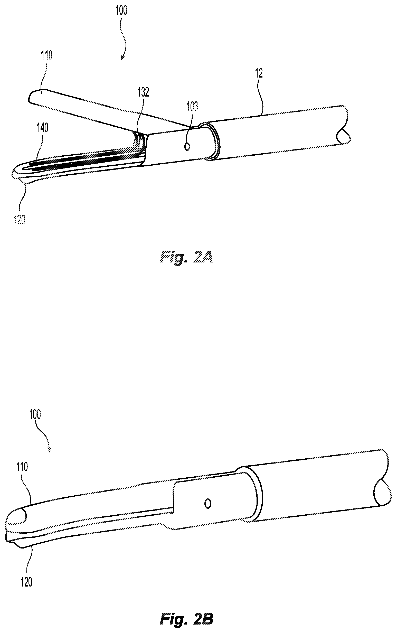
FIG. 2A is an enlarged, side, perspective view of a distal portion of the surgical instrument of FIG. 1 shown with opposing jaw members disposed in an open position;
FIG. 2B is an enlarged, side, perspective view of the distal portion of the surgical instrument of FIG. 1 shown in a closed position;
FIG. 3A is an enlarged, perspective view of an elongated electrode assembly for use with the forceps of FIG. 1;
FIG. 3B is an enlarged, side, perspective view of a tissue clip for use with the surgical instrument of FIG. 1 shown in an open position;
FIG. 3C is an enlarged, side, perspective view of the tissue clip shown mounted within the jaws of the surgical instrument of FIG. 1;
FIG. 3D is an enlarged, side, perspective view of the tissue clip deformed about tissue; and
FIG. 4 is a schematic illustration of a medical work station and operating console in accordance with the present disclosure.
DETAILED DESCRIPTION
Particular embodiments of the present disclosure are described hereinbelow with reference to the accompanying drawings in which like reference numerals designate identical or corresponding elements in each of the several views. As used herein, the term "distal" refers to that portion of the system, device, and/or component(s) thereof, which is farther from the user, while the term "proximal" refers to that portion of the system, device, and/or component(s) thereof, which is closer to the user. In the following description, well-known functions or constructions are not described in detail to avoid obscuring the present disclosure in unnecessary detail.
Surgical systems in accordance with the present disclosure can include endoscopic and/or open surgical instruments such as forceps devices, ultrasonic dissection devices, and/or any other suitable surgical devices. Obviously, different electrical and mechanical connections and considerations apply to each particular type of device; however, the aspects and features of the present disclosure remain generally consistent regardless of the particular device used. For a detailed description of the construction and operation of exemplary surgical devices, reference may be made to U.S. Patent Application Publication No. 2013/0255063, U.S. Patent Application Publication No. 2012/0083786 and/or U.S. Pat. No. 8,444,664, the entirety of each of which is incorporated by reference herein.
In the interest of brevity, surgical systems of the present disclosure will only be described herein in connection with an endoscopic surgical forceps.
Turning now to FIGS. 1, 2A, and 2B, an electrosurgical endoscopic forceps 10 is provided. Forceps 10 has a longitudinal axis "A-A" defined therethrough, a housing 20, a handle assembly 30, a rotating assembly 70, a trigger assembly 80 and an end effector assembly 100 including first and second jaw members 110 and 120. Jaw members 110 and 120, or portions thereof, may be made from dielectric or insulative materials such as plastic (e.g., thermoplastic, thermosetting plastic, etc.), ceramic material, etc.
The forceps 10 further includes a shaft 12 having a distal end 14 configured to mechanically engage the end effector assembly 100 and a proximal end 16 that mechanically engages the housing 20. The forceps 10 also includes an electrosurgical cable 18 that connects the forceps 10 to a generator 500 (FIG. 3B) or other suitable power source. Alternately, the forceps 10 may be configured as a battery powered instrument. A cable 18, which may include one or more wires, extends through the shaft 12 to provide electrical energy to one or both of the jaw members 110, 120 of end effector assembly 100 as described in greater detail below. The handle assembly 30 supports an electrical switch 50 operatively coupled to the cable 18 to provide electrical energy from the electrosurgical energy source (e.g., generator or battery) to one or both of the jaw members 110, 120 upon actuation of the electrical switch 50.
End effector assembly 100 may be designed as a unilateral assembly, e.g., where the second jaw member 120 is fixed relative to the shaft 12 and the first jaw member 110 is moveable about a pivot 103 relative to the shaft 12 and the second jaw member 120. The handle assembly 30 includes a stationary handle 32 and a movable handle 34 that is operatively coupled to a drive mechanism 40. The movable handle 34 is movable relative to the stationary handle 32 to cause the drive mechanism 40 to pivot the first jaw member 110 about the pivot 103. In some embodiments, the end effector assembly 100 may alternatively be configured as a bilateral assembly, e.g., where both the first and second jaw members 110, 120 are moveable about the pivot 103 relative to one another and to the shaft 12. Other than jaw member 110 being movable and jaw member 120 being stationary, jaw members 110 and 120 are generally identical to one another.
In certain embodiments, the first and second jaw members 110, 120 are configured to move in parallel relation to one another between an open (unapproximated) position and a closed (approximated) position. A knife assembly 130 may be disposed within the shaft 12 and opposing knife channels 112, 122 which are defined within the first and second jaw members 110, 120, respectively, to permit reciprocation of a knife blade 132 (FIG. 2A) of the knife assembly 130 therethrough, e.g., via activation of a trigger 82 of the trigger assembly 80. Knife channels 112, 122 are positioned in vertical registration with one another and cooperate as a unit when jaw members 110, 120 are disposed in a closed (approximated) position to enable reciprocation of the knife blade 132 through the jaw members 110, 120.
Turning now to FIGS. 3A-3D, a clip 140 may be used to facilitate sealing of tissue "T". More particularly, FIG. 3A shows an electrode assembly including a pair of elongated, malleable electrodes 142 and 144 separated by an insulating material 143, FIG. 3B shows the electrodes 142 and 144 twisted and deformed into a tissue clip 140 which is configured for use with end effector 100 of forceps 10, FIG. 3C shows the tissue clip 140 mounted between jaw members 110 and 120 of the end effector assembly 100 and ready for use, and FIG. 3D shows the tissue clip 140 in the deformed configuration about tissue "T".
As mentioned above, elongated electrodes 142 and 144 are made from a malleable, electrically conductive material to facilitate deformation into a tissue clip 140 for use with vessel sealing. Each electrode 142 and 144 is configured to connect to an electrical energy source, e.g., generator 500, and conduct respective first and second electrical potentials through tissue "T" when held between electrodes 142 and 144. An electrical insulator 143 is disposed between electrodes 142 and 144 and serves to isolate the electrodes 142 and 144 during activation and sealing. Together, electrodes 142 and 144 and insulator 143 form the electrode assembly 146.
In order to form the tissue clip 140 for use with vessel sealing procedures as shown in FIG. 3B, the electrodes 142 and 144 are initially twisted 180 degrees proximate their respective centers 147 and then folded into a generally U-shaped clip 140. Alternatively, the electrodes 142 and 144 could be formed in a U-shape and then twisted or simultaneously twisted and formed. In embodiments, a V-shaped clip may be formed. Once formed, electrode 142 includes upper and lower portions 142a, 142b and electrode 144 includes upper and lower portions 144a, 144b. By initially twisting (or folding then twisting) the electrodes 142 and 144 and forming the tissue clip 140, electrode portion 144a and electrode portion 142b form the inner facing surface of tissue clip 140 which mutually grip tissue when the electrodes 142 and 144 are deformed. Portions 142a and 144b form the outer peripheral surface of clip 140 and are configured to electrically couple to respective first and second electrical potentials via electrical connectors 160 and 162. When mounted within end effector assembly 100 and as shown in FIG. 3B, upper portion 142a releasably engages inner surface 111 of jaw member 110 and once energized, supplies energy to lower portion 142b and lower portion 144b releasably engages inner surface 121 of jaw member 120 and once energized, supplies energy to upper portion 144a. Upper portion 142a and lower portion 144b of tissue clip 140 may include one or more mechanical features to releasably engage the inner peripheral surfaces of respective jaw members 110 and 120.
In use, the movable handle 34 is actuated to enable the first and second jaw members 110, 120 to move from the open position to the closed position to thereby grasp tissue "T" disposed between the first and second jaw members 110, 120 while deforming the tissue clip 140 onto the tissue "T" disposed between the first and second jaw members 110, 120. As the first and second jaw members 110, 120 move toward the closed position, electrode portions 144a and 142b engage tissue "T" such that, upon activation, electrosurgical energy is transmitted through tissue "T" to create a tissue seal. Electrosurgical energy can be supplied to the electrode portions 144a and 142b prior to, during, and/or after deformation of the tissue clip 140 depending upon a particular purpose.
Once deformed about tissue "T" and energized to create a tissue seal, tissue clip 140 may be released from the jaw members 110 and 120 and removed by the surgeon and the tissue "T" may be cut along the tissue seal if desired. Alternatively, tissue clip 140 including electrode 142, electrode 144 and insulation 143 may be made from biodegradable materials that dissolve over time and, in such cases, tissue clip 140 may be left in situ. In embodiments, a second clip (not shown) may be deformed and energized adjacent the initial clip 140 to create a second tissue seal. A knife or cutting element 132 may be utilized to cut the tissue "T" between the two tissue seals.
One or more mechanical interfaces (not shown) may be employed to mount tissue clip 140 within jaw members 110 and 120 respectively, e.g., flanges, snap-like features, grooves, detents, etc. In embodiments, upon deformation, the mechanical interfaces that mount the tissue clip 140 to the jaw members 110 and 120 may likewise deform and automatically release the tissue clip 140 once fully deformed. In other embodiments, one or more of the mechanical interfaces may automatically reset after deformation and release of the tissue clip 140 to facilitate alignment and mounting a second or additional tissue clips 140. Yet in other embodiments, the tissue clip 140 is simply retained within the jaw members 110 and 120 via friction-fit engagement.
In embodiment, the tissue clip 140 may be mounted within the jaw members 110 and 120 in a skewed of laterally offset orientation such that the knife channels 112 and 122 are exposed. Once the tissue clip 140 is deformed and energized about tissue "T", the knife blade 132 may be advanced along the side of the tissue clip 140 to cut the tissue "T" (or vessel). In this scenario, the tissue clip 140 is intended for use as an end clip when the opposite end of the tissue "T" is being removed. Alternatively, this jaw member 110 and 120 and tissue clip 140 arrangement may be utilized between two clips and the knife blade 132 may be advanced to sever tissue disposed between the two tissue clips once deformed and a seal is created on either side of the tissue "T". Clip may also include one or more channels (not shown) defined therein that allow the knife 132 to translate through the tissue clip 140 once the tissue clip 140 is deformed.
Any of the presently disclosed clips can be formed of any suitable bio-compatible material. In some embodiments, any of the presently disclosed clips, or portions thereof, may be formed of a dielectric material. In certain embodiments, any of the presently disclosed clips, or portions thereof, may be formed of an electrically conductive material, whereby any of the presently disclosed clips may be utilized as an electrical conduit (e.g., via any of the presently described tissue-contacting surfaces) for conducting electrically energy directly and/or indirectly to tissue "T" to facilitate sealing of the tissue "T."
Any of the presently described jaw members 110 and 120, or portions thereof, may be made include dielectric or insulative material such as plastic (e.g., thermoplastic, thermosetting plastic, etc.), ceramic material, etc.
In some embodiments, one or more stop members 220 may be included on any of the presently described tissue-contacting portions of electrodes 144a, 142b (inner portions of the tissue clip 140). The stop members 220 may be made from insulative, non-conductive or conductive materials depending upon a particular purpose and depending upon the particular configuration of stop members 220 and various applicable electrical considerations. Such stop members 220 may function to provide a specific gap distance "G" between the tissue contacting portions 144a and 142b of the electrodes 144 and 142b when the tissue clip 140 is deformed which prevents the tissue-contacting portions 144a and 142b from contacting one another during the transmission of electrical energy and provides for a higher quality seal. In embodiments, the gap "G" is within a range of about 0.001 inches to about 0.006 inches.
In embodiments, the forceps 10 may be configured to close the jaw members 110 and 120 and the tissue clip 140 about tissue under a particular closure pressure within the range of about 3 kg/cm.sup.2 to about 16 kg/cm.sup.2. Once deformed and released from the jaw members 110 and 120, the tissue clip 140 may be designed to maintain the closure pressure within the above pressure range while deformed.
A method of forming a tissue clip 140 is also disclosed and includes disposing an insulative material 143 between first and second elongated electrodes 142 and 144 to create an electrode assembly 146. The method also includes twisting the electrode assembly 146 along a center portion 147 thereof; and deforming the electrode assembly 146 to form a generally U-shaped or V-shaped configuration having upper and lower legs 141a and 141b and the central portion 147. The upper leg 141a includes an outer facing portion including one end of the first electrode 142a configured to removably and electrically couple to a first jaw member 110 of a forceps 10 and an inner facing portion including an end of the second electrode 144a configured to grasp tissue. The lower leg 141b includes an outer facing portion including an opposite end of the second electrode 144b configured to removably and electrically couple to a second, opposing jaw member 120 of the forceps 10 and an inner facing portion including the opposite end of the first electrode 142b configured to grasp tissue.
A method of sealing tissue using a tissue clip 140 is also disclosed herein and includes disposing an insulative material 143 between first and second elongated electrodes 142 and 144 to create an electrode assembly 146. The method also includes twisting the electrode assembly 146 along a center portion 147 thereof; deforming the electrode assembly 146 to form a generally U-shaped configuration having upper and lower legs 141a and 141b, respectively, and the central portion 147, wherein the upper leg 141a includes an outer portion having one end of the first electrode 142 configured to removably and electrically couple to a first jaw member 110 of a forceps 10 and an inner facing portion including an end of the second electrode 144a configured to grasp tissue, the lower leg 141b including an outer portion having an opposite end of the second electrode 144b configured to removably and electrically couple to a second, opposing jaw member 120 of the forceps 10 and an inner facing portion including the opposite end of the first electrode 142b configured to grasp tissue; loading the tissue clip 140 into the first and second jaw members 110 and 120, respectively; approximating tissue with the jaw members 110 and 120 and the tissue clip 140; closing the jaw members 110 and 120 and tissue clip 140 about tissue; energizing the electrodes 142 and 144 utilizing an electrosurgical energy source 500 to create a tissue seal; and releasing the tissue clip 140 from the jaw members 110 and 120.
Energizing the electrodes 142 and 144 may include energizing the jaw members 110 and 120 which, in turn, energize the upper and lower legs 141a and 141b of the tissue clip 140. The closing the jaw members 110 and 120 and tissue clip 140 about tissue includes actuating a drive rod 40 from forceps 10. The closing of the jaw members 110 and 120 and tissue clip 140 about tissue "T" may include closing the jaw members 110 and 120 and tissue clip 140 about the tissue under a pressure within the range of about 3 kg/cm.sup.2 to about 16 kg/cm.sup.2.
In embodiments, the closing the jaw members 110 and 120 and tissue clip 140 about tissue includes creating a gap "G" between the opposing inner facing portions 144a and 142b of the electrodes 142 and 144. The creating of a gap "G" may include utilizing at least one stop member 220 on at least one inner facing portion of one of the electrodes, e.g., portion 142b. The creating of a gap "G" may include utilizing at least one stop member 220 on at least one inner facing portion of one of the electrodes, e.g., portion 142b, to create a gap "G" within a range of about 0.001 inches to about 0.006 inches between opposing inner facing portions 142b and 144a.
The various embodiments disclosed herein may also be configured to work with robotic surgical systems and what is commonly referred to as "Telesurgery." Such systems employ various robotic elements to assist the surgeon and allow remote operation (or partial remote operation) of surgical instrumentation. Various robotic arms, gears, cams, pulleys, electric and mechanical motors, etc. may be employed for this purpose and may be designed with a robotic surgical system to assist the surgeon during the course of an operation or treatment. Such robotic systems may include remotely steerable systems, automatically flexible surgical systems, remotely flexible surgical systems, remotely articulating surgical systems, wireless surgical systems, modular or selectively configurable remotely operated surgical systems, etc.
The robotic surgical systems may be employed with one or more consoles that are next to the operating theater or located in a remote location. In this instance, one team of surgeons or nurses may prep the patient for surgery and configure the robotic surgical system with one or more of the instruments disclosed herein while another surgeon (or group of surgeons) remotely control the instruments via the robotic surgical system. As can be appreciated, a highly skilled surgeon may perform multiple operations in multiple locations without leaving his/her remote console which can be both economically advantageous and a benefit to the patient or a series of patients.
The robotic arms of the surgical system are typically coupled to a pair of master handles by a controller. The handles can be moved by the surgeon to produce a corresponding movement of the working ends of any type of surgical instrument (e.g., end effectors, graspers, knifes, scissors, etc.) which may complement the use of one or more of the embodiments described herein. The movement of the master handles may be scaled so that the working ends have a corresponding movement that is different, smaller or larger, than the movement performed by the operating hands of the surgeon. The scale factor or gearing ratio may be adjustable so that the operator can control the resolution of the working ends of the surgical instrument(s).
The master handles may include various sensors to provide feedback to the surgeon relating to various tissue parameters or conditions, e.g., tissue resistance due to manipulation, cutting or otherwise treating, pressure by the instrument onto the tissue, tissue temperature, tissue impedance, etc. As can be appreciated, such sensors provide the surgeon with enhanced tactile feedback simulating actual operating conditions. The master handles may also include a variety of different actuators for delicate tissue manipulation or treatment further enhancing the surgeon's ability to mimic actual operating conditions.
Referring also to FIG. 4, a medical work station is shown generally as work station 1000 and generally may include a plurality of robot arms 1002, 1003; a control device 1004; and an operating console 1005 coupled with the control device 1004. The operating console 1005 may include a display device 1006, which may be set up in particular to display three-dimensional images; and manual input devices 1007, 1008, by means of which a person (not shown), for example a clinician, may be able to telemanipulate the robot arms 1002, 1003 in a first operating mode.
Each of the robot arms 1002, 1003 may include a plurality of members, which are connected through joints, and an attaching device 1009, 1011, to which may be attached, for example, a surgical tool "ST" supporting an end effector 1100 (e.g., a pair of jaw members), in accordance with any one of several embodiments disclosed herein, as will be described in greater detail below.
The robot arms 1002, 1003 may be driven by electric drives (not shown) that are connected to the control device 1004. The control device 1004 (e.g., a computer) may be set up to activate the drives, in particular by means of a computer program, in such a way that the robot arms 1002, 1003, their attaching devices 1009, 1011 and thus the surgical tool (including the end effector 1100) execute a desired movement according to a movement defined by means of the manual input devices 1007, 1008. The control device 1004 may also be set up in such a way that it regulates the movement of the robot arms 1002, 1003 and/or of the drives.
The medical work station 1000 may be configured for use on a patient "P" lying on a patient table 1012 to be treated in a minimally invasive manner by means of the end effector 1100. The medical work station 1000 may also include more than two robot arms 1002, 1003, the additional robot arms likewise connected to the control device 1004 and telemanipulatable by means of the operating console 1005. A medical instrument or surgical tool (including an end effector 1100) may also be attached to the additional robot arm. The medical work station 1000 may include a database 1014 coupled with the control device 1004. In some embodiments, pre-operative data from patient/living being "P" and/or anatomical atlases may be stored in the database 1014.
Persons skilled in the art will understand that the structures and methods specifically described herein and shown in the accompanying figures are non-limiting exemplary embodiments, and that the description, disclosure, and figures should be construed merely as exemplary of particular embodiments. It is to be understood, therefore, that the present disclosure is not limited to the precise embodiments described, and that various other changes and modifications may be effected by one skilled in the art without departing from the scope or spirit of the disclosure. Additionally, the elements and features shown or described in connection with certain embodiments may be combined with the elements and features of certain other embodiments without departing from the scope of the present disclosure, and that such modifications and variations are also included within the scope of the present disclosure. Accordingly, the subject matter of the present disclosure is not limited by what has been particularly shown and described.
* * * * *
D00000
D00001
D00002
D00003
D00004
D00005
D00006
XML
uspto.report is an independent third-party trademark research tool that is not affiliated, endorsed, or sponsored by the United States Patent and Trademark Office (USPTO) or any other governmental organization. The information provided by uspto.report is based on publicly available data at the time of writing and is intended for informational purposes only.
While we strive to provide accurate and up-to-date information, we do not guarantee the accuracy, completeness, reliability, or suitability of the information displayed on this site. The use of this site is at your own risk. Any reliance you place on such information is therefore strictly at your own risk.
All official trademark data, including owner information, should be verified by visiting the official USPTO website at www.uspto.gov. This site is not intended to replace professional legal advice and should not be used as a substitute for consulting with a legal professional who is knowledgeable about trademark law.