Shock wave catheter system with energy control
Adams Dec
U.S. patent number 10,517,620 [Application Number 15/347,486] was granted by the patent office on 2019-12-31 for shock wave catheter system with energy control. This patent grant is currently assigned to SHOCKWAVE MEDICAL, INC.. The grantee listed for this patent is SHOCKWAVE MEDICAL, INC.. Invention is credited to John M. Adams.


| United States Patent | 10,517,620 |
| Adams | December 31, 2019 |
Shock wave catheter system with energy control
Abstract
A system includes a catheter including an elongated carrier, a balloon about the carrier in sealed relation thereto, the balloon being arranged to receive a fluid therein that inflates the balloon, and first and second electrodes within the balloon arranged to carry a voltage there-across including an initial high electrical voltage at an initial low current. The initial high electrical voltage causes an electrical arc to form across the first and second electrodes within the balloon. The electrical arc causes a gas bubble within the liquid, a high current to flow through the first and second electrodes, a decrease in the initial high electrical voltage, and a mechanical shock wave within the balloon. The system further includes a power source that provides the first and second electrodes with a drive voltage that creates the initial high electrical voltage at the initial current and that terminates the drive voltage in response to the decrease in the initial high electrical voltage.
| Inventors: | Adams; John M. (Snohomish, WA) | ||||||||||
|---|---|---|---|---|---|---|---|---|---|---|---|
| Applicant: |
|
||||||||||
| Assignee: | SHOCKWAVE MEDICAL, INC. (Santa
Clara, CA) |
||||||||||
| Family ID: | 51569674 | ||||||||||
| Appl. No.: | 15/347,486 | ||||||||||
| Filed: | November 9, 2016 |
Prior Publication Data
| Document Identifier | Publication Date | |
|---|---|---|
| US 20170056035 A1 | Mar 2, 2017 | |
Related U.S. Patent Documents
| Application Number | Filing Date | Patent Number | Issue Date | ||
|---|---|---|---|---|---|
| 14218858 | Mar 18, 2014 | 9522012 | |||
| 13615107 | May 10, 2016 | 9333000 | |||
| Current U.S. Class: | 1/1 |
| Current CPC Class: | A61B 17/22022 (20130101); A61B 2017/22081 (20130101); A61B 2017/22062 (20130101); A61B 2017/22025 (20130101) |
| Current International Class: | A61B 17/22 (20060101) |
References Cited [Referenced By]
U.S. Patent Documents
| 3413976 | December 1968 | Roze |
| 3785382 | January 1974 | Schmidt et al. |
| 3902499 | September 1975 | Shene |
| 4027674 | June 1977 | Tessler et al. |
| 4662126 | May 1987 | Malcolm |
| 4671254 | June 1987 | Fair |
| 4685458 | August 1987 | Leckrone |
| 4809682 | March 1989 | Forssmann et al. |
| 4900303 | February 1990 | Lemelson |
| 5009232 | April 1991 | Hassler et al. |
| 5057103 | October 1991 | Davis |
| 5057106 | October 1991 | Kasevich et al. |
| 5078717 | January 1992 | Parins et al. |
| 5103804 | April 1992 | Abele et al. |
| 5116227 | May 1992 | Levy |
| 5152767 | October 1992 | Sypal et al. |
| 5152768 | October 1992 | Bhatta |
| 5176675 | January 1993 | Watson et al. |
| 5245988 | September 1993 | Einars et al. |
| 5246447 | September 1993 | Rosen et al. |
| 5281231 | January 1994 | Rosen et al. |
| 5321715 | June 1994 | Trost |
| 5324255 | June 1994 | Passafaro et al. |
| 5336234 | August 1994 | Vigil et al. |
| 5362309 | November 1994 | Carter |
| 5368591 | November 1994 | Lennox et al. |
| 5395335 | March 1995 | Jang |
| 5417208 | May 1995 | Winkler |
| 5425735 | June 1995 | Rosen et al. |
| 5472406 | December 1995 | de la Torre et al. |
| 5582578 | December 1996 | Zhong et al. |
| 5603731 | February 1997 | Whitney |
| 5609606 | March 1997 | O''Boyle |
| 5662590 | September 1997 | de la Torre et al. |
| 5931805 | August 1999 | Brisken |
| 6007530 | December 1999 | Doernhoefer et al. |
| 6033371 | March 2000 | Torre et al. |
| 6083232 | July 2000 | Cox |
| 6186963 | February 2001 | Schwarze et al. |
| 6210408 | April 2001 | Chandrasekaran et al. |
| 6217531 | April 2001 | Reitmajer |
| 6277138 | August 2001 | Levinson et al. |
| 6287272 | September 2001 | Brisken et al. |
| 6352535 | March 2002 | Lewis et al. |
| 6367203 | April 2002 | Graham et al. |
| 6371971 | April 2002 | Tsugita et al. |
| 6398792 | June 2002 | O''Connor |
| 6406486 | June 2002 | de la Torre et al. |
| 6514203 | February 2003 | Bukshpan |
| 6524251 | February 2003 | Rabiner et al. |
| 6589253 | July 2003 | Cornish et al. |
| 6607003 | August 2003 | Wilson |
| 6638246 | October 2003 | Naimark et al. |
| 6652547 | November 2003 | Rabiner et al. |
| 6736784 | May 2004 | Menne et al. |
| 6740081 | May 2004 | Hilal |
| 6755821 | June 2004 | Fry |
| 6989009 | January 2006 | Lafontaine |
| 7241295 | July 2007 | Maguire |
| 7569032 | August 2009 | Naimark et al. |
| 8556813 | October 2013 | Cioanta et al. |
| 8728091 | May 2014 | Hakala et al. |
| 8747416 | June 2014 | Hakala et al. |
| 8888788 | November 2014 | Hakala et al. |
| 8956371 | February 2015 | Hawkins et al. |
| 9005216 | April 2015 | Hakala et al. |
| 9011463 | April 2015 | Adams et al. |
| 9333000 | May 2016 | Hakala et al. |
| 9522012 | December 2016 | Adams |
| 10159505 | December 2018 | Hakala et al. |
| 2001/0044596 | November 2001 | Jaafar |
| 2002/0045890 | April 2002 | Celliers et al. |
| 2002/0177889 | November 2002 | Brisken et al. |
| 2003/0004434 | January 2003 | Greco et al. |
| 2003/0176873 | September 2003 | Chernenko et al. |
| 2003/0229370 | December 2003 | Miller |
| 2004/0044308 | March 2004 | Naimark et al. |
| 2004/0097963 | May 2004 | Seddon |
| 2004/0097996 | May 2004 | Rabiner et al. |
| 2004/0162508 | August 2004 | Uebelacker |
| 2004/0254570 | December 2004 | Hadjicostis et al. |
| 2005/0015953 | January 2005 | Keidar |
| 2005/0021013 | January 2005 | Visuri et al. |
| 2005/0113722 | May 2005 | Schultheiss |
| 2005/0228372 | October 2005 | Truckai et al. |
| 2005/0251131 | November 2005 | Lesh |
| 2006/0004286 | January 2006 | Chang et al. |
| 2006/0184076 | August 2006 | Gill et al. |
| 2006/0190022 | August 2006 | Beyar et al. |
| 2006/0221528 | October 2006 | Li et al. |
| 2007/0088380 | April 2007 | Hirszowicz et al. |
| 2007/0239082 | October 2007 | Schultheiss et al. |
| 2007/0239253 | October 2007 | Jagger et al. |
| 2007/0244423 | October 2007 | Zumeris et al. |
| 2007/0250052 | October 2007 | Wham |
| 2007/0282301 | December 2007 | Segalescu et al. |
| 2008/0097251 | April 2008 | Babaev |
| 2008/0188913 | August 2008 | Stone et al. |
| 2009/0041833 | February 2009 | Bettinger et al. |
| 2009/0247945 | October 2009 | Levit et al. |
| 2009/0254114 | October 2009 | Hirszowicz et al. |
| 2009/0312768 | December 2009 | Hawkins et al. |
| 2010/0016862 | January 2010 | Hawkins et al. |
| 2010/0036294 | February 2010 | Mantell et al. |
| 2010/0114020 | May 2010 | Hawkins et al. |
| 2010/0114065 | May 2010 | Hawkins et al. |
| 2010/0121322 | May 2010 | Swanson |
| 2010/0305565 | December 2010 | Truckai et al. |
| 2011/0034832 | February 2011 | Cioanta et al. |
| 2011/0118634 | May 2011 | Golan |
| 2011/0166570 | July 2011 | Hawkins et al. |
| 2011/0257523 | October 2011 | Hastings et al. |
| 2011/0295227 | December 2011 | Hawkins et al. |
| 2012/0071889 | March 2012 | Mantell et al. |
| 2012/0095461 | April 2012 | Herscher et al. |
| 2012/0203255 | August 2012 | Hawkins et al. |
| 2012/0221013 | August 2012 | Hawkins et al. |
| 2013/0030431 | January 2013 | Adams |
| 2013/0030447 | January 2013 | Adams |
| 2013/0041355 | February 2013 | Heeren et al. |
| 2013/0150874 | June 2013 | Kassab |
| 2014/0046229 | February 2014 | Hawkins et al. |
| 2014/0052147 | February 2014 | Hakala et al. |
| 2014/0074111 | March 2014 | Hakala et al. |
| 2014/0243820 | August 2014 | Adams et al. |
| 2014/0243847 | August 2014 | Hakala et al. |
| 2014/0288570 | September 2014 | Adams |
| 2015/0073430 | March 2015 | Hakala et al. |
| 2015/0238208 | August 2015 | Adams et al. |
| 2016/0183957 | June 2016 | Hakala et al. |
| 1204242 | Jan 1999 | CN | |||
| 1942145 | Apr 2007 | CN | |||
| 3038445 | May 1982 | DE | |||
| 0442199 | Aug 1991 | EP | |||
| 57106 | Nov 1993 | EP | |||
| 62-275446 | Nov 1987 | JP | |||
| 6-125915 | May 1994 | JP | |||
| 7-47135 | Feb 1995 | JP | |||
| 10-99444 | Apr 1998 | JP | |||
| 10-513379 | Dec 1998 | JP | |||
| 2002-538932 | Nov 2002 | JP | |||
| 2004-81374 | Mar 2004 | JP | |||
| 2005-95410 | Apr 2005 | JP | |||
| 2005-515825 | Jun 2005 | JP | |||
| 2006-516465 | Jul 2006 | JP | |||
| 2007-289707 | Nov 2007 | JP | |||
| 2007-532182 | Nov 2007 | JP | |||
| 2011-524203 | Sep 2011 | JP | |||
| 2012-508042 | Apr 2012 | JP | |||
| 1996/024297 | Aug 1996 | WO | |||
| 2004/069072 | Aug 2004 | WO | |||
| 2005/099594 | Oct 2005 | WO | |||
| 2005/102199 | Nov 2005 | WO | |||
| 2006/127158 | Nov 2006 | WO | |||
| 2007/149905 | Dec 2007 | WO | |||
| 2009/121017 | Oct 2009 | WO | |||
| 2009/152352 | Dec 2009 | WO | |||
| 2010/014515 | Feb 2010 | WO | |||
| 2011/143468 | Nov 2011 | WO | |||
| 2013/059735 | Apr 2013 | WO | |||
Other References
|
Notice of Acceptance received for Australian Patent Application No. 2013315444, dated Jul. 26, 2017, 3 pages. cited by applicant . Office Action received for Australian Patent Application No. 2013315444, dated Nov. 30, 2016, 3 pages. cited by applicant . Office Action received for Chinese Patent Applicatbn No. 201380047277.3, dated Mar. 1, 2017, 10 pages (5 pages of English Translation and 5 pages of Official Copy Only). cited by applicant . Office Action received for Chinese Patent Applicatbn No. 201380047277.3, dated May 16, 2017, 13 pages.(6 pages of English Translation and 7 pages of Official Copy). cited by applicant . Office Action received for Japanese Patent Application No. 2015-532052, dated Aug. 21, 2017, 12 pages (6 pages of English Translation and 6 pages of Official Copy). cited by applicant . Advisory Action Received for U.S. Appl. No. 12/482,995, dated Jun. 2, 2014, 3 pages. cited by applicant . Advisory Action Received for U.S. Appl. No. 12/482,995, dated Sep. 29, 2011, 2 pages. cited by applicant . Final Office Action received for U.S. Appl. No. 12/482,995, dated Feb. 20, 2014, 11 pages. cited by applicant . Non Final Office Action received for U.S. Appl. No. 12/482,995, dated Aug. 13, 2014, 10 pages. cited by applicant . Non Final Office Action received for U.S. Appl. No. 12/482,995, dated Jul. 12, 2013, 11 pages. cited by applicant . Notice of Allowance received for U.S. Appl. No. 12/482,995, dated Dec. 24, 2014, 6 pages. cited by applicant . Non-Final Office Action received for U.S. Appl. No. 12/501,619, dated Jan. 28, 2014, 10 pages. cited by applicant . Advisory Action Received for U.S. Appl. No. 12/581,295, dated Jul. 3, 2014, 3 pages. cited by applicant . Final Office Action received for U.S. Appl. No. 12/581,295, dated Jun. 5, 2014, 14 pages. cited by applicant . Non-Final Office Action received for U.S. Appl. No. 12/581,295, dated Jan. 15, 2015, 14 pages. cited by applicant . Non-Final Office Action received for U.S. Appl. No. 12/581,295, dated Mar. 10, 2014, 11 pages. cited by applicant . Notice of Allowance received for U.S. Appl. No. 12/581,295, dated Jul. 10, 2015, 15 pages. cited by applicant . Notice of Allowance received for U.S. Appl. No. 12/581,295, dated Jul. 29, 2015, 7 pages. cited by applicant . Advisory Action Received for U.S. Appl. No. 13/049,199, dated Jun. 7, 2012, 3 pages. cited by applicant . Final Office Action received for U.S. Appl. No. 13/049,199 dated Aug. 11, 2014, 8 pages. cited by applicant . Non-Final Office Action received for U.S. Appl. No. 13/049,199, dated Feb. 4, 2014, 8 pages. cited by applicant . Notice of Allowance received for U.S. Appl. No. 13/049,199, dated Dec. 15, 2014, 7 pages. cited by applicant . Notice of Allowance received for U.S. Appl. No. 13/049,199, dated Jan. 13, 2015, 4 pages. cited by applicant . Advisory Action received for U.S. Appl. No. 13/267,383, dated Jan. 6, 2014, 4 pages. cited by applicant . Final Office Action Received for U.S. Appl. No. 13/267,383, dated May 28, 2015, 12 pages. cited by applicant . Final Office Action received for U.S. Appl. No. 13/267,383, dated Oct. 25, 2013, 8 pages. cited by applicant . Non-Final Office Action received for U.S. Appl. No. 13/267,383, dated Feb. 25, 2015, 9 pages. cited by applicant . Non Final Office Action received for U.S. Appl. No. 13/465,264, dated Oct. 29, 2014, 13 pages. cited by applicant . Non-Final Office Action received for U.S. Appl. No. 13/465,264, dated Dec. 23, 2014, 13 pages. cited by applicant . Notice of Allowance received for U.S. Appl. No. 13/465,264, dated May 8, 2015, 7 pages. cited by applicant . Advisory Action received for U.S. Appl. No. 13/615,107, dated Nov. 6, 2015, 3 pages. cited by applicant . Final Office Action received for U.S. Appl. No. 13/615,107 dated Sep. 1, 2015, 9 pages. cited by applicant . Non-Final Office Action received for U.S. Appl. No. 13/615,107, dated Apr. 24, 2015, 9 pages. cited by applicant . Notice of Allowance received for U.S. Appl. No. 13/615,107, dated Dec. 31, 2015, 10 pages. cited by applicant . Final Office Action received for U.S. Appl. No. 13/646,570, dated Dec. 23, 2014, 10 pages. cited by applicant . Non Final Office Action received for U.S. Appl. No. 13/646,570, dated Oct. 29, 2014, 10 pages. cited by applicant . Notice of Allowance received for U.S. Appl. No. 13/646,570, dated Mar. 11, 2015, 7 pages. cited by applicant . Non-Final Office Action received for U.S. Appl. No. 13/646,583, dated Oct. 31, 2014, 8 pages. cited by applicant . Notice of Allowance received for U.S. Appl. No. 13/777,807, dated May 19, 2015, 13 pages. cited by applicant . Notice of Allowance received for U.S. Appl. No. 13/831,543, dated Oct. 8, 2014, 14 pages. cited by applicant . Non-Final Office Action received for U.S. Appl. No. 14/061,554, dated Mar. 12, 2014, 14 pages. cited by applicant . Notice of Allowance received for U.S. Appl. No. 14/061,554, dated Apr. 25, 2014, 8 pages. cited by applicant . Non Final Office Action received for U.S. Appl. No. 14/079,463, dated Mar. 4, 2014, 9 pages. cited by applicant . Notice of Allowance received for U.S. Appl. No. 14/079,463, dated Apr. 1, 2014, 5 pages. cited by applicant . Non-Final Office Action received for U.S. Appl. No. 14/271,276, dated Aug. 4, 2014, 7 pages. cited by applicant . Notice of Allowance received for U.S. Appl. No. 14/271,276, dated Feb. 25, 2015, 8 pages. cited by applicant . Final Office Action received for U.S. Appl. No. 14/271,342 dated Feb. 27, 2015, 7 pages. cited by applicant . Non-Final Office Action received for U.S. Appl. No. 14/271,342, dated Sep. 2, 2014, 6 pages. cited by applicant . Notice of Allowance received for U.S. Appl. No. 14/271,342, dated Mar. 13, 2015, 5 pages. cited by applicant . Notice of Allowance received for Canadian Patent Application No. 2,727,429, dated May 26, 2015, 1 page. cited by applicant . Office Action received for Canadian Patent Application No. 2,727,429, dated Apr. 14, 2015, 4 pages. cited by applicant . Notice of Acceptance Received for Australian Patent Application No. 2009257368, dated Aug. 28, 2014, 2 pages. cited by applicant . Office Action received for Australian Patent Application No. 2009257368, dated Apr. 28, 2014, 4 pages. cited by applicant . Office Action received for Australian Patent Application No. 2009257368, dated Jul. 31, 2013, 4 pages. cited by applicant . Decision to Grant received for Japanese Patent Application No. 2011-513694, dated Oct. 7, 2014, 3 pages. cited by applicant . Office Action received for Japanese Patent Application No. 2011-513694, dated Aug. 27, 2013, 6 pages. cited by applicant . Office Action Received for Japanese Patent Application No. 2011-513694, dated Jun. 10, 2014, 4 pages. cited by applicant . Office Action Received for Japanese Patent Application No. 2014-158517, dated May 19, 2015, 5 pages. cited by applicant . Cleveland et al., "The Physics of Shock Wave Lithotripsy", Extracorporeal Shock Wave Lithotripsy Part IV, Chapter 38, 2012, pp. 317-332. cited by applicant . Connors et al., "Renal Nerves Mediate Changes in Contralateral Renal Blood Flow after Extracorporeal Shockwave Lithotripsy", Nephron Physiol, vol. 95, 2003, pp. 67-75. cited by applicant . Gambihler et al., "Permeabilization of the Plasma Membrane of LI210 Mouse Leukemia Cells Using Lithotripter Shock Waves", The Journal of Membrane Biology, vol. 141, 1994, pp. 267-275. cited by applicant . Grassi et al., "Novel Antihypertensive Therapies: Renal Sympathetic Nerve Ablation and Carotid Baroreceptor Stimulation", Curr Hypertens Rep vol. 14, 2012, pp. 567-572. cited by applicant . Kodama et al., "Shock wave-mediated molecular delivery into cells", Biochimica et Biophysica Acta, vol. 1542, 2002, pp. 186-194. cited by applicant . Lauer et al., "Shock wave permeabilization as a new gene transfer method", Gene Therapy vol. 4, 1997, pp. 710-715. cited by applicant . International Preliminary Report on Patentability received for PCT Patent Application No. PCT/US2009/047070, dated Dec. 23, 2010, 7 pages. cited by applicant . International Search Report received for PCT Patent Application No. PCT/US2009/047070, dated Jan. 19, 2010, 4 pages. cited by applicant . International Written Opinion received for PCT Patent Application No. PCT/US2009/047070, dated Jan. 19, 2010, 5 pages. cited by applicant . International Preliminary Report on Patentability received for PCT Patent Application No. PCT/US2011/047070, dated Feb. 21, 2013, 7 pages. cited by applicant . International Written Opinion received for PCT Patent Application No. PCT/US2011/047070, dated May 1, 2012, 5 pages. cited by applicant . International Preliminary Report on Patentability received for PCT Patent Application No. PCT/US2012/023172, dated Aug. 15, 2013, 6 pages. cited by applicant . International Search Report received for PCT Patent Application No. PCT/US2012/023172, dated Sep. 28, 2012, 3 pages. cited by applicant . International Written Opinion received for PCT Patent Application No. PCT/US2012/023172, dated Sep. 28, 2012, 4 pages. cited by applicant . International Preliminary Report on Patentability received for PCT Patent Application No. PCT/US2013/031805, dated Feb. 19, 2015, 11 pages. cited by applicant . International Search Report and Written Opinion received for PCT Patent Application No. PCT/US2013/031805, dated May 20, 2013, 13 pages. cited by applicant . International Preliminary Report on Patentability received for PCT Patent Application No. PCT/US2013/039987, dated Nov. 20, 2014, 11 pages. cited by applicant . International Search Report and Written Opinion received for PCT Patent Application No. PCT/US2013/039987, dated Sep. 23, 2013, 15 pages. cited by applicant . International Preliminary Report on Patentability received for PCT Patent Application No. PCT/US2013/048277, dated Jan. 8, 2015, 9 pages. cited by applicant . International Search Report and Written Opinion received for PCT Patent Application No. PCT/US2013/048277, dated Oct. 2, 2013, 14 pages. cited by applicant . International Preliminary Report on Patentability received for PCT Patent Application No. PCT/US2013/055431, dated Feb. 26, 2015, 7 pages. cited by applicant . International Search Report and Written Opinion received for PCT Patent Application No. PCT/US2013/055431, dated Nov. 12, 2013, 9 pages. cited by applicant . International Preliminary Report on Patentability received for PCT Patent Application No. PCT/US2013/059533, dated Mar. 26, 2015, 10 pages. cited by applicant . International Search Report and Written Opinion received for PCT Patent Application No. PCT/US2013/059533, dated Nov. 7, 2013, 14 pages. cited by applicant . Rosenschein et al., "Shock-Wave Thrombus Ablation, a New Method for Noninvasive Mechanical Thrombolysis", The American Journal of Cardiology, vol. 70, Nov. 15, 1992, pp. 1358-1361. cited by applicant . Zhong et al., "Transient Oscillation of Cavitation Bubbles Near Stone Surface During Electohydraulic Lithotripsy", Journal of Endourology, vol. 11, No. 1, Feb. 1997, pp. 55-61. cited by applicant . Notice of Allowance received for U.S. Appl. No. 14/515,130, dated May 2, 2016, 8 pages. cited by applicant . Non Final Office Action received for U.S. Appl. No. 14/515,130, dated Jan. 14, 2016, 16 pages. cited by applicant . Extended European Search Report received for European Patent Application No. 13827971.6, dated Apr. 12, 2016, 8 pages. cited by applicant . Extended European Search Report (includes Supplementary European Search Report and Search Opinion) received for European Patent Application No. 09763640.1, dated Oct. 10, 2013, 5 pages. cited by applicant . Non Final Office Action received for U.S. Appl. No. 13/534,658, dated Mar. 11, 2016, 12 pages. cited by applicant . Notice of Allowance received for U.S. Appl. No. 14/218,858, dated Aug. 26, 2016, 8 pages. cited by applicant . Non Final Office Action received for U.S. Appl. No. 14/218,858, dated Mar. 30, 2016, 13 pages. cited by applicant . Office Action received for Chinese Patent Application No. 201380047277.3, dated Aug. 19, 2016, 12 Pages ( 5 pages of English Translation and 7 Pages of Official Copy). cited by applicant . Non-Final Office Action received for U.S. Appl. No. 15/065,607, dated Feb. 22, 2018, 8 pages. cited by applicant . Notice of Allowance received for Chinese Patent Application No. 201380047277.3, dated Nov. 6, 2017, 2 pages (Official Copy Only) (See Communication under 37 CFR .sctn. 1.98(a) (3)). cited by applicant . Notice of Allowance received for Japanese Patent Application No. 2015-532052, dated Jun. 25, 2018, 3 pages (Official Copy Only) (See Communication under 37 CFR .sctn. 1.98(a) (3)). cited by applicant . Notice of Allowance received for U.S. Appl. No. 15/065,607, dated Aug. 10, 2018, 7 pages. cited by applicant . Office Action received for Japanese Patent Application No. 2015-532052, dated Feb. 6, 2018, 9 pages (6 pages of English Translation and 3 pages of Official Copy). cited by applicant . Broyer et al., "High-Efficiency Shock-Wave Generator for Extracorporeal Lithotripsy", Medical and Biological Engineering and Computing, vol. 34, Sep. 1996, pp. 321-328. cited by applicant . Cleveland et al., "Design and Characterization of a Research Electrohydraulic Lithotripter Patterned after the Dornier HM3", Review of Scientific Instruments, vol. 71, No. 6, Jun. 2000, pp. 2514-2525. cited by applicant . Declaration of Dr. Morten Olgaard Jensen on Dec. 6, 2018, 138 pages. cited by applicant . Dodd, A. T. S., "Two Cases of Calculus in the Bladder, in Which Lithotripsy Was Performed", Provincial Medical & Surgical Journal, vol. 3, No. 71, 1842, pp. 368-370. cited by applicant . Grocela et al., "Intracorporeal Lithotripsy. Instrumentation and Development", Urologic Clinics of North America, vol. 24, No. 1, Feb. 1997, pp. 13-23. cited by applicant . Kaplan et al., "Healing after Arterial Dilatation with Radiofrequency Thermal and Nonthermal Balloon Angioplasty Systems", Journal of Investigative Surgery, vol. 6, Jul. 9, 1993, pp. 33-52. cited by applicant . Manousakas et al., "A High-Voltage Discharging System for Extracorporeal Shock-Wave Therapy", IFMBE Proceedings, vol. 23, 2009, pp. 706-707. cited by applicant . Nisonson et al., "Ambulatory Extracorporeal Shockwave Lithotripsy", Urology, vol. 28, No. 5, Nov. 1986, pp. 381-384. cited by applicant . Patterson et al., "The Etiology and Treatment of delayed Bleeding following Percutaneous Lithotripsy", The Journal of Urology, vol. 133, 1985, pp. 447-451. cited by applicant . Petition for Inter Partes Review of U.S. Pat. No. 8,728,091, issued on May 20, 2014, 74 pages. cited by applicant . Prosecution History of U.S. Appl. No. 14/079,463, issued as U.S. Pat. No. 8,728,091, 860 pages. cited by applicant . Tanaka et al., "A New Radiofrequency Thermal Balloon Catheter for Pulmonary Vein Isolation", Journal of the American College of Cardiology, vol. 38, No. 7, Dec. 2001, pp. 2079-2086. cited by applicant . Ardley, Tim, "First Principles of a Gas Discharge Tube (GDT) Primary Protector", Bourns, Rev. 2, Available Online at <https://www.mouser.com/pdfdocs/bourns_gdt_white paper.pdf>, 2008, pp. 1-34. cited by applicant . Bank of America Merrill Lynch, "A Simple Solution to a Difficult (and Large) Problem--Initiating Coverage of SWAV", Shockwave Medical Inc., Apr. 1, 2019, pp. 1-22. cited by applicant . Bittl et al., "Coronary Artery Perforation during Excimer Laser Coronary Angioplasty", Journal of the American College of Cardiology, vol. 21, No. 5, Apr. 1993, pp. 1158-1165. cited by applicant . Bittl et al., "Publication Information--Coronary Artery Perforation during Excimer Laser Coronary Angioplasty", Journal of the American College of Cardiology, vol. 21, No. 5, Apr. 1993, pp. 1-6. cited by applicant . Brinton et al., "Publication Information--TCT-777 Safety and Performance of the Shockwave Medical Lithoplasty.RTM. System in Treating Calcified Peripheral Vascular Lesions: 6-Month Results from the Two-Phase Disrupt Pad Study", Journal of the American College of Cardiology, vol. 68, No. 18, Supplement, Nov. 2016, pp. 1-5. cited by applicant . Brinton et al., "TCT-777 Safety and Performance of the Shockwave Medical Lithoplasty.RTM. System in Treating Calcified Peripheral Vascular Lesions: 6-Month Results from the Two-Phase Disrupt Pad Study", Journal of the American College of Cardiology, vol. 68, No. 18, Supplement B, 2016, p. B314. cited by applicant . Cardiology Today'S Intervention, "Shockwave Attracts Additional Investment from Abiomed, has IPO", Available Online at <https://www.healio.com/cardiac-vascular-intervention/peripheral/news/- online/%7Bf96c1e20-b4a9-4167-bdb8-254e86a8182a%7D/shockwave-attracts-addit- ional-investment-from-abiomed-has-ipo>, Mar. 12, 2019, pp. 1-2. cited by applicant . US 2003/0176873, Chernenko et, al., Fig. 4b and Fig. 5 from Drawings as filed on Mar. 12, 2002, pp. 1-2. cited by applicant . Citel, Inc., "Gas Discharge Overview," (http://www.citel.us/gas_discharge_tubes_overview.html). cited by applicant . Deagon, Brian, "Technology--Shockwave Medical IPO Soars on First Day of Trading", Investor's Business Daily, Available Online at <https://www.investors.com/news/technology/shockwave-medical-ipo-soars- -trading/>, Mar. 7, 2019, pp. 1-15. cited by applicant . Decision of Inter Partes Review for U.S. Pat. No. 8,728,091, by the Patent Trial and Appeal Board dated Jul. 11, 2019, pp. 1-32. cited by applicant . Declaration of Natalie J. Grace on Apr. 14, 2019, pp. 1-5. cited by applicant . Declaration of William Patrick Stephens on Apr. 14, 2019, pp. 1-6. cited by applicant . Elmansy et al., "Publication Information--Recent Advances in Lithotripsy Technology and Treatment Strategies: A Systematic Review Update", International Journal of Surgery, vol. 36, Part D, Dec. 2016, pp. 1-6. cited by applicant . Elmansy et al., "Recent Advances in Lithotripsy Technology and Treatment Strategies: A Systematic Review Update", International Journal of Surgery, vol. 36, 2016, pp. 676-680. cited by applicant . "FDA Clears Lithoplasty Balloon That Shatters Calcified Lesions With Ultrasound", Diagnostic and Interventional Cardiology, Available Online at <https://www.dicardiology.com/product/fda-clearslithoplasty-balloon- -shatters-calcified-lesions-ultrasound>, Sep. 16, 2016, pp. 1-5. cited by applicant . Knight, D. W., "Gas Discharge Tubes--Introduction", G3YNH.info, Available Online at <http://g3ynh.info/disch_tube/intro.html>, 2013, pp. 1-9. cited by applicant . Mills et al., "Cracking the Code on Calcium; Initiate with Buy, $39 Target", Canaccord Genuity--Capital Markets, US Equity Research, Apr. 1, 2019, pp. 1-63. cited by applicant . Mitomo, Satoru, "Intravascular lithotripsy: A Novel Technology for Treating Calcified Coronary Stenoses", Cardiovascular News, Online Available at <https://cardiovascularnews.com/intravascular-lithotripsy-anovel-techn- ology-for-treating-calcified-coronary-stenoses>, Apr. 18, 2018, pp. 1-4. cited by applicant . Motisan, "Relaxation Oscillator Using a Hydrogen Thyratron", PocketMagic, Available Online at <https://www.pocketmagic.net/relaxation-oscillator-using-a-hydrogenthy- ratron)>, Oct. 9, 2011, pp. 1-5. cited by applicant . Patent Owner Preliminary Response for U.S. Pat. No. 8,728,091, Patent Trial and Appeal Board dated Apr. 14, 2019, pp. 1-68. cited by applicant . Ricks, Delthia, "Long Island Doctors Using Sound Waves to Loosen Calcium Deposits from Arteries, Restore Blood Flow", News/Health, Available Online at <https://www.newsday.com/news/health/calcium-treatment-st-fr- ancis-hospital-1.27314331>, Feb. 15, 2019, pp. 1-4. cited by applicant . Shockwavemedical.com, "Intravascular Lithotripsy (IVL)", Available Online at <https://shockwavemedical.com/technology/intravascular-lithotripsy-- ivl/?country=Egypt>, 2019, pp. 1-4. cited by applicant . Texas Instruments, "Power Management Guide", Available Online at <http://www.ti.com/lit/sg/slvt145r/slvt145r.pdf>, 2018, pp. 1-93. cited by applicant . "Top Cardiovascular Innovation Award", Cardiovascular Research Technologies (CRT), 2015, p. 1. cited by applicant . Wells Fargo Securities LLC, "SWAV: Initiating With a Market Perform Rating", Shockwave Medical Inc., Apr. 1, 2019, pp. 1-34. cited by applicant . Zhong et al., "Publication Information--Transient Oscillation of Cavitation Bubbles Near Stone Surface During Electrohydraulic Lithotripsy", Journal of Endourology, vol. 11, No. 1, 1997, 1 page. cited by applicant. |
Primary Examiner: Dang; Phong Son H
Attorney, Agent or Firm: Morrison & Foerster LLP
Parent Case Text
CROSS-REFERENCE TO RELATED APPLICATION
This application is a divisional of U.S. application Ser. No. 14/218,858, filed Mar. 18, 2014 which was in turn, a continuation-in-part of U.S. application Ser. No. 13/615,107 filed on Sep. 13, 2012, issued as U.S. Pat. No. 9,333,000 on May 10, 2016, both of which are incorporated herein by reference in its entirety for all purposes.
Claims
What is claimed is:
1. A method for delivering shock waves to a calcified lesion comprising: providing a catheter including an elongated carrier, a balloon about the carrier in sealed relation thereto, the balloon being arranged to receive a fluid therein that inflates the balloon, and first and second electrodes within the balloon; introducing the fluid into the balloon to inflate the balloon; applying a drive voltage pulse across the first and second electrodes to form an electrical arc within the fluid; sensing voltage across the first and second electrodes during the voltage pulse; and terminating the application of that drive voltage pulse across the first and second electrodes when the sensed voltage associated with that voltage pulse decreases by more than a predetermined amount.
2. The method of claim 1, wherein the predetermined amount is one-hundred volts.
3. The method of claim 1, wherein the predetermined amount is five-hundred volts.
4. The method of claim 1 including the further step of timing a delay time when the sensed voltage decreases by more than a predetermined amount of voltage and then terminating the application of that drive voltage pulse.
5. The method of claim 4, wherein the predetermined amount is one-hundred volts.
6. The method of claim 4, wherein the predetermined amount is five-hundred volts.
7. A method for delivering shock waves to a calcified lesion comprising: advancing a balloon catheter to a calcified lesion, wherein the balloon catheter includes an elongated carrier, a balloon, and a pair of electrodes on the elongated carrier within the balloon, wherein the electrodes are immersed in a fluid within the balloon and wherein the electrodes are connected to a power source; activating the power source to supply one or more voltage pulses to the electrodes such that during each pulse, there is an initial high voltage across the electrodes such that an arc is generated in the fluid and a current flows between the electrodes producing a shock wave; detecting when the voltage across the electrodes is reduced from the initial high voltage by a predetermined voltage value; and terminating the voltage supplied to the electrodes after the detected voltage is reduced by the predetermined voltage value during that pulse.
8. The method of claim 7 wherein the predetermined voltage value is 100 V.
9. The method of claim 7 wherein the predetermined voltage value is 500 V.
10. The method of claim 7, wherein the detecting step further includes detecting whether the voltage across the electrodes has been reduced by the predetermined voltage value within a predetermined time interval.
11. The method of claim 10, wherein the predetermined time interval is from 0.1 microseconds to 0.5 microseconds.
12. The method of claim 7, wherein after the detecting step and before the terminating step, waiting a predetermined delay time before terminating the voltage supplied to the electrodes.
13. The method of claim 12, wherein the predetermined delay time is 100 nanoseconds or more.
14. A method for delivering shock waves to a calcified lesion comprising: advancing a catheter to a calcified lesion, with the distal end of the catheter carrying a pair of electrodes immersed in fluid, wherein the electrodes are connected to a power source; activating the power source to supply one or more voltage pulses to the electrodes such that during each pulse, there is an initial high voltage across the electrodes such that an arc is generated in the fluid and a current flows between the electrodes producing a shock wave; detecting when the voltage across the electrodes is reduced from the initial high voltage by a predetermined voltage value; and terminating the voltage supplied to the electrodes after the detected voltage is reduced by the predetermined voltage value during that pulse.
15. A method as recited in claim 14 wherein the electrode pair is located within a sealed member.
16. The method of claim 14, wherein the detecting step further includes detecting whether the voltage across the electrodes has been reduced by the predetermined voltage value within a predetermined time interval.
17. The method of claim 14, wherein after the detecting step and before the terminating step, waiting a predetermined delay time before terminating the voltage supplied to the electrodes.
18. The method of claim 17, wherein the predetermined delay time is 100 nanoseconds or more.
Description
BACKGROUND OF THE INVENTION
The present invention relates to a treatment system for percutaneous coronary angioplasty or peripheral angioplasty in which a dilation catheter is used to cross a lesion in order to dilate the lesion and restore normal blood flow in the artery. It is particularly useful when the lesion is a calcified lesion in the wall of the artery. Calcified lesions require high pressures (sometimes as high as 10-15 or even 30 atmospheres) to break the calcified plaque and push it back into the vessel wall. With such pressures comes trauma to the vessel wall which can contribute to vessel rebound, dissection, thrombus formation, and a high level of restenosis. Non-concentric calcified lesions can result in undue stress to the free wall of the vessel when exposed to high pressures. An angioplasty balloon when inflated to high pressures can have a specific maximum diameter to which it will expand but the opening in the vessel under a concentric lesion will typically be much smaller. As the pressure is increased to open the passage way for blood the balloon will be confined to the size of the opening in the calcified lesion (before it is broken open). As the pressure builds a tremendous amount of energy is stored in the balloon until the calcified lesion breaks or cracks. That energy is then released and results in the rapid expansion of the balloon to its maximum dimension and may stress and injure the vessel walls.
Recently, a new system and method has been contemplated for breaking up calcium deposits in, for example, arteries and veins. Such a system is described, for example in U.S. Patent Publication No. 2009/0312768, Published Dec. 17, 2009. Embodiments described therein include a catheter having balloon, such as an angioplasty balloon, at the distal end thereof arranged to be inflated with a fluid. Disposed within the balloon is a shock wave generator that may take the form of, for example, a pair of electrodes, which are coupled to a high voltage source at the proximal end of the catheter through a connector. When the balloon is placed adjacent a calcified region of a vein or artery and a high voltage pulse is applied across the electrodes, a shock wave is formed that propagates through the fluid and impinges upon the wall of the balloon and the calcified region. Repeated pulses break up the calcium without damaging surrounding soft tissue.
Each high voltage pulse causes an arc to form across the electrodes. The arc in turn causes a steam bubble to form. Each steam bubble has the potential of producing two shock waves, a leading edge shock wave as a result of bubble expansion and a trailing edge shock wave as a result of bubble collapse. The trailing edge shock waves exhibit highly variable energy levels and generally, much greater energy levels than the leading edge shock waves. The energy levels of the trailing edge shock waves are substantially dependent on the uniformity of the bubble collapse. The uniform collapse of spherical bubbles to a point appears to create the highest shock wave energies. Unfortunately, spherical bubble configuration requires a substantially larger space than is available in a balloon that must fit into a calcified vein or artery or even a ureter. In fact, the trailing edge shock wave can be substantially eliminated by confining the bubble to an irregular shape. As a result, for angioplasty or other cardiac and non-cardiac applications of shock waves, the trailing edge shock wave cannot be reliably relied upon to produce consistent results.
However, the leading edge shock waves formed by bubble expansion are a different matter. While exhibiting generally lower energies, they are more consistent in energy level. As a result, leading edge shock waves are good candidates for use in medical procedures such, for example, angioplasty or valvuloplasty.
Another consideration is the amount of energy represented by the high voltage applied to the electrodes. Each high voltage pulse removes a portion of the electrode material. Since the size of the electrodes must be small in order to fit into the calcified vein or artery, they are only capable of sustaining a limited numbers of high voltage pulses sufficient to form the shock wave resulting electrical arc.
Also, it has been learned that to sustain a leading edge shock wave, it is not necessary to sustain the high voltage throughout the shock wave. Sustaining the high voltage beyond some point after the initial arc does not lead to shock waves of any greater intensity. Further, since the bubbles are formed of steam, the steam produces heat which can increase the temperature of adjacent soft tissue. Just a two degree Celsius elevation in temperature above body temperature can result in tissue damage.
A still further important aspect of prior art attempts to use shock waves from electrical arcs for therapeutic purposes is that from the time the high voltage is first applied to the electrodes to the time in which the arc occurs there is a dwell time (Td) that is highly variable from one high voltage application to the next. To account for the dwell times that are long, prior art strategies have relied upon high voltage applications where all high voltage pulse durations or pulse widths are of the same length and of a length sufficient to extend through the longest of the anticipated dwell times plus the associated arc and steam bubble. As a result, when the dwell times are shorter than the maximum, the high voltage application durations are longer than necessary and can unnecessarily extend the arc and the steam bubble well beyond a time required to produce a shock wave of maximum intensity. The result is wasted energy, extended electrode erosion, and unnecessary heating of the adjoining tissue.
Hence, there is a need in the art to be able to control the energy applied to the electrodes of an electrical arc shock wave generator. More particularly, there is a need to control the applied energy to assure appropriate bubble and shock wave formation while at the same time conserving electrode material and assuring tissue safety. The present invention addresses these and other issues.
SUMMARY OF THE INVENTION
In one embodiment, a system includes a catheter including an elongated carrier, a balloon about the carrier in sealed relation thereto, the balloon being arranged to receive a fluid therein that inflates the balloon, and first and second electrodes within the balloon arranged to carry a voltage there-across including an initial high electrical voltage at an initial low current. The initial high electrical voltage causes an electrical arc to form across the first and second electrodes within the balloon. The electrical arc causes a gas bubble within the liquid, a high current to flow through the first and second electrodes, a decrease in the initial high electrical voltage, and a mechanical shock wave within the balloon. The system further includes a power source that provides the first and second electrodes with a drive voltage that creates the initial high electrical voltage at the initial current and that terminates the drive voltage in response to the decrease in the initial high electrical voltage.
The power source may include a voltage sensor that senses the voltage across the first and second electrodes. The voltage sensor is arranged to cause the power source to terminate the drive voltage when the voltage across the first and second electrodes decreases by more than a predetermined amount of voltage within less than a predetermined amount of time.
The predetermined amount of voltage may be on the order of one-hundred volts and the predetermined time may be on the order of about 0.1 microseconds. Alternatively, the predetermined amount of voltage may be on the order of five-hundred volts and the predetermined time may be on the order of about 0.5 microseconds.
The system may further include a temperature sensor within the balloon that senses temperature of the fluid within the balloon, and the power source may be further responsive to the temperature sensor. The temperature sensor may cause the power source to decrease energy applied to the first and second electrodes responsive to the temperature of the fluid within the balloon increasing to control the temperature of the fluid.
The temperature sensor may be arranged to cause the power source to decrease energy applied to the first and second electrodes responsive to the temperature of the fluid within the balloon increasing to above two degrees Celsius above ambient temperature.
The balloon may be a dilation balloon. The dilation balloon is preferably an angioplasty balloon.
The system may further include a timer that times a delay time in response to the decrease in the initial high electrical voltage and the power source may be arranged to terminate the drive voltage after the delay time is timed.
The power source may include a voltage sensor that senses voltage across the first and second electrodes and the voltage sensor may be arranged to cause the timer to time the delay time when the voltage across the first and second electrodes decreases by more than a predetermined amount of voltage within less than a predetermined amount of time. The predetermined amount of voltage may be on the order of one-hundred volts and the predetermined time is on the order of about 0.1 microseconds. Alternatively, the predetermined amount of voltage may be on the order of five-hundred volts and the predetermined time is on the order of about 0.5 microseconds.
In another embodiment, a system includes a catheter including an elongated carrier, the carrier having a guide wire lumen, a balloon having an inner surface about the carrier in sealed relation thereto, the balloon forming with the carrier, a channel arranged to receive a fluid that inflates the balloon, and first and second electrodes within the balloon between the carrier and the inner surface of the balloon. The first and second electrodes within the balloon are arranged to carry a voltage there-across including an initial high electrical voltage at an initial low current. The initial high electrical voltage causes an electrical arc to form across the first and second electrodes within the balloon. The electrical arc causes a gas bubble within the liquid, a high current to flow through the first and second electrodes, a decrease in the initial high electrical voltage, and a mechanical shock wave within the balloon. The system further includes a power source that provides the first and second electrodes with a drive voltage that creates the initial high electrical voltage at the initial current and that terminates the drive voltage in response to the decrease in the initial high electrical voltage.
In a further embodiment, a method includes the steps of: providing a catheter including an elongated carrier, a balloon about the carrier in sealed relation thereto, the balloon being arranged to receive a fluid therein that inflates the balloon, and first and second electrodes within the balloon and introducing the fluid into the balloon to inflate the balloon. The method further includes the steps of applying a drive voltage across the first and second electrodes to form an electrical arc across the first and second electrodes, sensing voltage across the first and second electrodes and varying the application of the drive voltage across the first and second electrodes in response to sensed voltage across the first and second electrodes after the electrical arc is formed across the first and second electrodes.
The varying step may include terminating the application of the drive voltage across the first and second electrodes.
The application of the drive voltage may be terminated when the voltage across the first and second electrodes decreases by more than a predetermined amount of voltage within less than a predetermined amount of time. The predetermined amount of voltage may be on the order of one-hundred volts and the predetermined time is on the order of 0.1 microseconds. Alternatively, the predetermined amount of voltage may be on the order of five-hundred volts and the predetermined time is on the order of about 0.5 microseconds.
The method may further include the step of sensing temperature of the fluid within the balloon, and the varying step may include varying the drive voltage across the first and second electrodes in response to sensed temperature of the fluid. The varying step may include decreasing energy applied to the first and second electrodes responsive to the temperature of the fluid within the balloon increasing to control the temperature of the fluid. The energy applied to the first and second electrodes may be decreased responsive to the temperature of the fluid within the balloon increasing to above two degrees Celsius above ambient temperature.
The method may further include the step of timing a delay time when the voltage across the first and second electrodes decreases by more than a predetermined amount of voltage within less than a predetermined amount of time.
The predetermined amount of voltage may be on the order of one-hundred volts and the predetermined time is on the order of about 0.1 microseconds. The predetermined amount of voltage may alternatively be on the order of five-hundred volts and the predetermined time is on the order of about 0.5 microseconds.
BRIEF DESCRIPTION OF THE DRAWINGS
The features of the present invention which are believed to be novel are set forth with particularity in the appended claims. The invention, together with further features and advantages thereof, may best be understood by making reference to the following description taken in conjunction with the accompanying drawings, in the several figures of which like reference numerals identify identical elements, and wherein:
FIG. 1 is a simplified side view of an angioplasty balloon catheter of the type that may utilize various embodiments of the invention to advantage;
FIG. 2 is a simplified side view of an electrode structure that may be employed in the catheter of FIG. 1 coupled to a source of high voltage pulses according to one embodiment of the invention;
FIG. 3 is a front plan view of the electrode structure of FIG. 2;
FIG. 4 is a simplified equivalent circuit diagram of a system according to an embodiment of the invention;
FIG. 5 is a graph illustrating a high voltage pulse applied to a pair of electrical arc shock wave producing electrodes and the resulting current flow through the electrodes in accordance with an embodiment of the invention;
FIG. 6 is a schematic diagram of a power source for use in an angioplasty electrical arc shock wave angioplasty catheter according to an embodiment of the invention;
FIG. 7 is a side view of a dilating catheter with an electrical arc producing electrode structure and a temperature probe therein according to aspects of the invention;
FIG. 8 is a schematic diagram of an angioplasty catheter system according to further embodiments of the invention;
FIG. 9 is a simplified side view, partly in section, of a further embodiment wherein a balloon is not required;
FIG. 10 is a flow diagram illustrating a further embodiment of the invention;
FIG. 11 is a schematic diagram of a power source for use in an angioplasty electrical arc shock wave angioplasty catheter according to a still further embodiment of the invention; and
FIG. 12 is a flow diagram illustrating one manner in which the power source of FIG. 11 may operate in accordance with a still further embodiment.
DETAILED DESCRIPTION OF THE INVENTION
FIG. 1 is a simplified side view of an angioplasty balloon catheter 20 of the type that may utilize various embodiments of the invention to advantage. The catheter 20 includes an elongated carrier, such as a hollow sheath 21, a dilating balloon 26 formed about the sheath 21 in sealed relation thereto and a guide wire member 28 to which the balloon is sealed at a seal 23. The guide wire member has a longitudinal lumen 29 through which a guide wire (not shown) may be received for directing the catheter 20 to a desired location within a vein or artery, for example.
The sheath 21 forms with the guide wire member 28 a channel 27 through which fluid, such as saline, may be admitted into the balloon to inflate the balloon. The channel 27 further permits the balloon 26 to be provided with an electrode pair 25 including electrodes 22 and 24 within the fluid filled balloon 26.
As may be seen in FIG. 2, the electrodes 22 and 24 are attached to a source 40 of high voltage pulses. As may be seen in FIG. 3, the electrodes 22 and 24 are coaxially disposed with electrode 22 being a center electrode and electrode 24 being a ring shaped electrode about electrode 22. The center electrode 22 is coupled to a positive terminal 44 of source 40 and the ring electrode 24 is coupled to a negative terminal 46 of the source 40. The electrodes 22 and 24 are formed of metal, such as stainless steel, and are maintained a controlled distance apart to allow a reproducible arc to form for a given applied voltage and current.
The electrical arcs between electrodes 22 and 24 in the fluid are used to generate shock waves in the fluid. Each pulse of high voltage applied to the electrodes 22 and 24 forms an arc across the electrodes. The voltage pulses may have amplitudes as low as 500 volts, but preferably, the voltage amplitudes are in the range of 1000 volts to 10,000 volts. The balloon 26 may be filled with water or saline in order to gently fix the balloon in the walls of the artery or vein, for example, in direct proximity with the calcified lesion. The fluid may also contain an x-ray contrast to permit fluoroscopic viewing of the catheter during use. Once the catheter 20 is positioned with the guide wire (not shown), the physician or operator can start applying the high voltage pulses to the electrodes to form the shock waves that crack the calcified plaque. Such shockwaves will be conducted through the fluid, through the balloon, through the blood and vessel wall to the calcified lesion where the energy will break the hardened plaque without the application of excessive pressure by the balloon on the walls of the artery.
FIG. 4 is a simplified equivalent circuit diagram of a system according to an embodiment of the invention. Here it may be seen that a capacitance stores a high voltage. When a switch 60 is closed, the voltage drop across the electrodes 22 and 24 begins to quickly rise at an initially low current level. After a dwell time, when the voltage across the electrodes reaches the breakdown voltage of the fluid between the electrodes, an electrical arc occurs across the electrodes. The arc causes a steam bubble to form between the electrodes and a relatively high current to flow through the electrodes. The expansion of the bubble forms a first or leading edge shock wave. After a time, the steam bubble cools and condenses causing the bubble to collapse. The collapsing bubble has the potential for forming a second or trailing edge shock wave. As previously mentioned, the trailing edge shock wave is relatively unreliable exhibiting inconsistent intensities from shock wave to shock wave. Hence, it is the leading edge shock wave that holds the most promise for reliable therapy.
It has been found that effective shock wave intensity may be accomplished without holding the high voltage pulses on during the entire extent of their corresponding steam bubbles. Moreover, terminating the application of the high voltage before steam bubble collapse can serve to preserve electrode material, permitting a pair of electrodes to last for an increased number of applied high voltage pulses. Still further, as will be seen subsequently, early termination of the high voltage can also be used to advantage in controlling the temperature within the balloon fluid.
FIG. 5 is a graph illustrating a high voltage pulse applied to a pair of electrical arc shock wave producing electrodes and the resulting current flow through the electrodes in accordance with an embodiment of the invention. When the switch 60 (FIG. 4) is first closed, the voltage across the electrodes quickly rises to a level 70. During this time, as shown by dashed lines 72, the current through the electrodes is relatively low. After a dwell time (Td), the arc occurs between the electrodes. At this time the steam bubble begins to form and a high current begins to flow through the electrodes. In accordance with embodiments of the invention, responsive to the current through the electrodes, the application of the high voltage is terminated. This conserves energy applied to the electrodes, causing the electrodes to remain useful for a greater number of pulses than otherwise would be the case if the high voltage were applied longer or sustained throughout the bubble existence. The advantages of controlling the applied energy in this manner are obtained without adversely affecting the intensity of the leading edge shock waves produced.
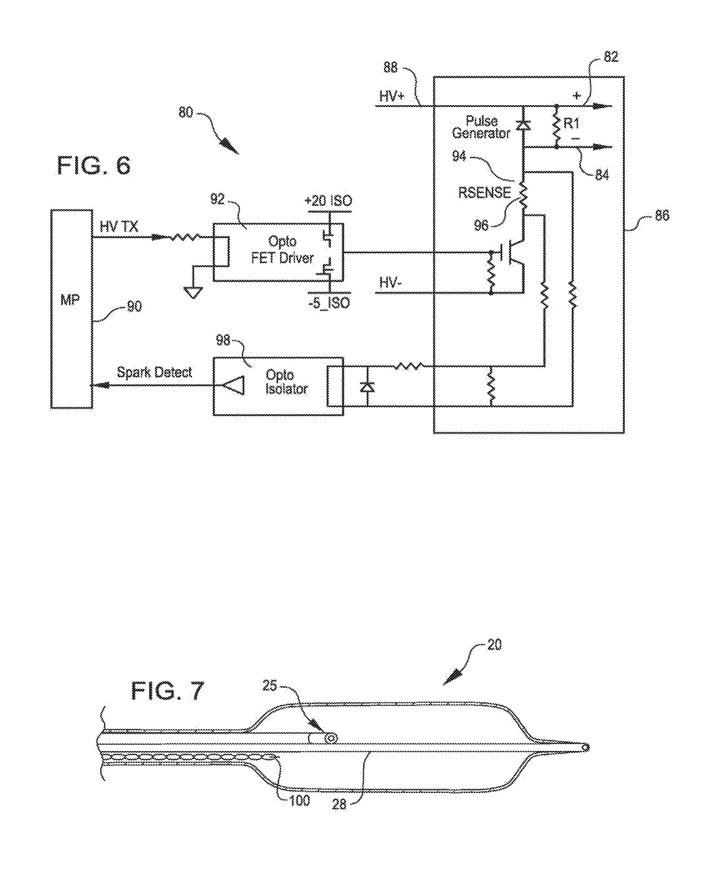
FIG. 6 is a schematic diagram of a power source 80 for use in an electrical arc shock wave angioplasty catheter according to an embodiment of the invention. The power source 80 has an output terminal 82 that may be coupled to electrode 22 of FIG. 1 and an output terminal 84 that may be coupled to electrode 24 of FIG. 1. A switch circuit 86 selectively applies a high voltage on line 88 across the electrodes. A microprocessor 90, or other similar control circuitry, such as a gate array, controls the overall operation of the source 80. A Field Programmable Gate Array (FPGA) may also be substituted for the microprocessor in a manner known in the art. The microprocessor 90 is coupled to the switch 86 by an optical driver 92. The switch includes a current sensor 94 that includes a current sensing resistor 96 that generates a signal that is applied to an optical isolator 98 when the current flowing through the electrodes reaches a predetermined limit, such as, for example, fifty (50) amperes.
In operation, the microprocessor 90 through the optical driver 92, causes the switch 86 to apply the high voltage to the electrodes 22 and 24. The current sensed through resister 96 is monitored by the microprocessor 90 through the optical isolator 98. When the current flowing through the electrodes reaches a predetermined limit, as for example 50 amperes, the microprocessor 90 causes the application of the high voltage to be terminated. The forgoing occurs for each high voltage pulse applied to the electrodes 22 and 24. Each pulse creates a shock wave of consistent and useful intensity. Further, because the application of the high voltage is terminated early, the electrode material is preserved to lengthen the useful life of the electrodes.
FIG. 7 is a side view of a dilating catheter with an electrical arc producing electrode structure and a temperature probe therein according to aspects of the invention. The catheter 20 of FIG. 7 may be the same catheter as shown in FIG. 1. Here however, the catheter 20 further includes a temperature probe or sensor 100. The temperature sensor may be employed for sensing the temperature of the fluid within the balloon. Preferably, the temperature of the fluid within the balloon 26 should not be permitted to rise more than two degrees Celsius above the ambient body temperature. If this were to occur, soft tissue damage may result.
FIG. 8 is a schematic diagram of an angioplasty catheter system 110 according to further embodiments of the invention which includes the catheter 20 and temperature probe 100. Here the system also includes the microprocessor 90, the switch 86, optical driver 92 and optical isolator 98. All of these elements may function as previously described. In addition, the temperature sensor 100 conveys a temperature signal through another optical isolator 120 indicative of the temperature of the fluid within the balloon 26. If the temperature within the balloon 26 rises to more than a certain temperature, for example to more than two degrees Celsius above ambient body temperature, the energy applied to the electrodes is decreased. This will decrease the size and duration of the steam bubbles produced by the electrodes to maintain the temperature of the fluid within the balloon to within safe limits. The microprocessor 90 may cause the switch 86 to decrease the pulse amplitude of the applied high voltage pulses or the pulse rate of the applied high voltage pulse. It could alternatively temporarily terminate the application of the pulses.
FIG. 9 is a simplified side view, partly in section, of a further embodiment wherein a balloon is not required. In this embodiment, a system 134, according to further aspects of the invention, is shown treating an obstruction, more particularly, a kidney stone 131. The system includes a catheter 133 that terminates at its distal end with an electrode pair 132 similar to electrode pair 25 of FIGS. 1 and 2. The system further includes a power source 140. The power source has a positive output terminal 142 and a negative output terminal 144. The center electrode of the electrode pair 132 may be coupled to the positive terminal 142 of source 140 and the ring electrode of the electrode pair 132 may be coupled to the negative terminal 144 of the source 140. The electrodes of the electrode pair 132 may be formed of metal, such as stainless steel, and are maintained a controlled distance apart to allow a reproducible arc to form for a given applied voltage and current.
The catheter 133 of system 134 is shown in a ureter 130. The ureter has a kidney stone 131 requiring treatment. According to this embodiment, voltage pulses are applied to the electrode pair 132 to produce leading edge shock waves as previously described. The shock waves propagate through the fluid within the ureter and impinge directly on the kidney stone 131. In a manner as previously described, the power source may be operated to maintain the energy applied to the electrode pair within limits to assure that the steam bubbles produced by the generated arcs do not harm the ureter. To that end, the amplitude or pulse rate of the applied voltages may be controlled. Hence, by controlling the energy of the current during the produced arc, such as by controlling the on time of the current, barotrauma to the ureter may be minimized even though a balloon is not employed as in previous embodiments. Of course, the system of FIG. 9 may be used in other body organs as well, such as the bile duct, for example.
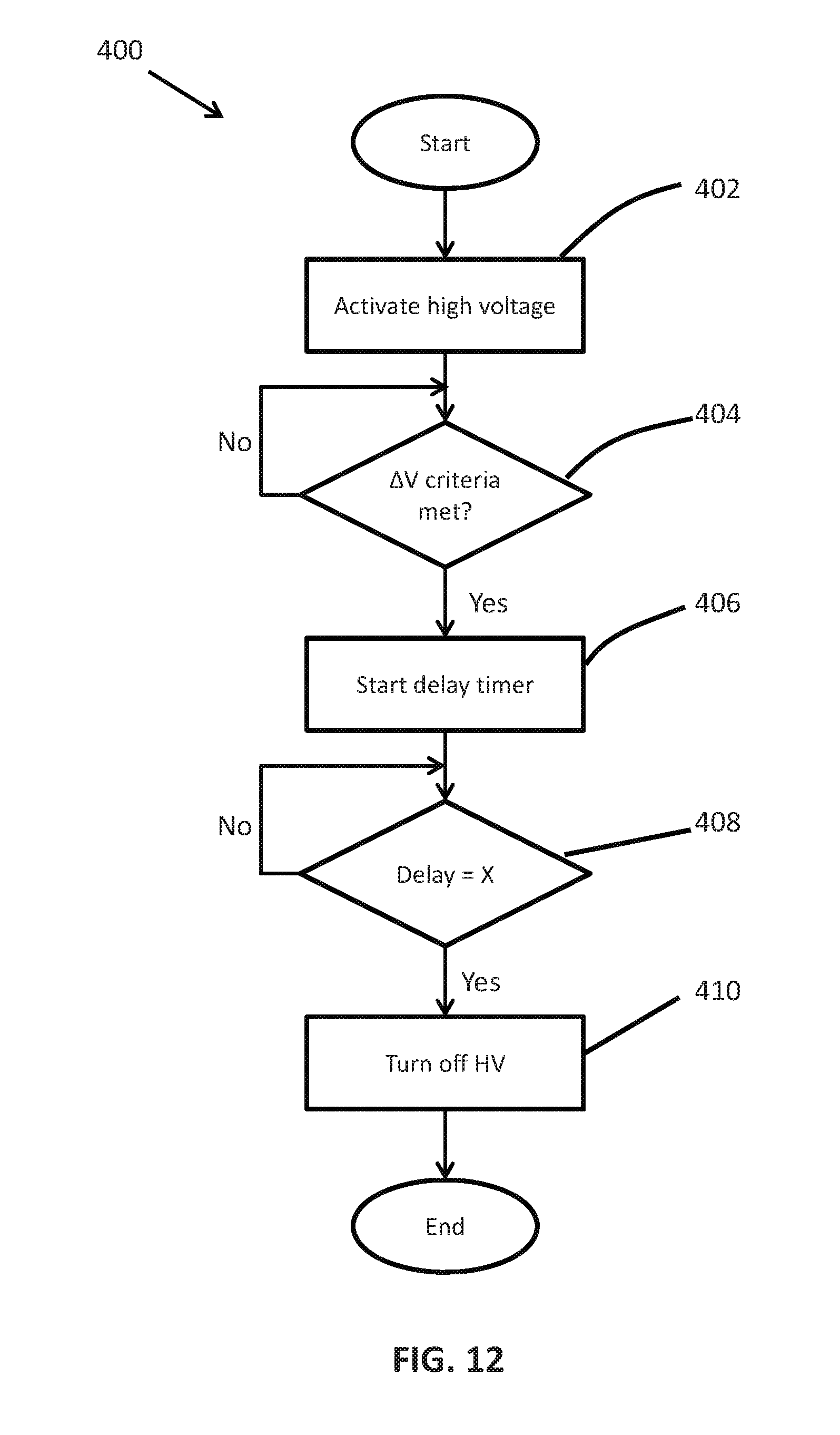
FIG. 10 is a flow diagram illustrating the process of a further embodiment of the invention. The embodiment of FIG. 10 takes into account the time it takes for a high voltage switch, such as switch 86 (FIG. 6), to turn off (the turn off time) and the rise time of the current flowing through the electrodes once the electrical arc starts. The current through the electrodes can eventually reach one-hundred amperes or more, at which point the maximum intensity shock wave will be formed. In order to permit the maximum current to be reached and to account for the turn off time of the switch 86, a delay is timed extending from when the current flowing through the electrodes is at a fixed threshold known to be below the maximum current, to the turn off time of the switch before the expected current maximum. For example, the current threshold may be fifty amperes. When the current through the electrodes equals fifty amperes, the delay timing is begun by the starting of a delay timer within the microprocessor 90. If the current is expected to be at a maximum 200 nanoseconds after the current reaches fifty amperes, and if it takes 100 nanoseconds for the high voltage switch to actually turn off after receiving a turn off signal, a delay of 100 nanoseconds should be timed from the 50 ampere sensing before a turn off signal is applied to the high voltage switch. Hence, a total time of 200 nanoseconds will pass after the current reaches 50 amperes and, as a result, will reach its maximum. As the current reaches its maximum, or shortly thereafter, the voltage applied to the electrodes will be terminated.
Referring now to the flow diagram 200 of FIG. 10, and also with reference to FIG. 6, the process begins with activity step 202 wherein the high voltage is applied to the output terminals 82 and 84 for application to the electrodes, for example, electrodes 22 and 24 (FIG. 1). At first, the current initially flowing through the electrodes is relatively low. However, after a dwell time, the applied high voltage causes an electrical arc to begin to form between the electrodes, the current through the electrodes is sensed, and the current rapidly rises. The current through the electrodes is sensed as previously described. At decision block 204, the microprocessor 90 determines if the sensed current has reached fifty amperes. When the current reaches fifty amperes, the process advances to activity block 206 where the timing of the aforementioned delay time (x) is started. Next, in decision block 208, it is determined when the delay time has been timed. In accordance with this embodiment, the delay time (x) may be 100 nanoseconds. When the delay time of 100 nanoseconds is timed, the process advances to activity block 210 wherein the process completes with a turn off signal being applied by the microprocessor 90 to the high voltage switch 86. The switch 86 will actually turn of a turn of time after the turn off signal is applied to the switch 86. Since it takes 100 nanoseconds for the switch to turn off and since 100 nanoseconds are timed before the turn off signal is applied to the switch, 200 nanoseconds form the 50 ampere current sensing will pass before the applied voltage to the electrodes is actually terminated. That provides sufficient time for the current to reach its maximum to generate the maximum intensity shock wave. The voltage application will terminated as the current reaches maximum, or shortly thereafter.
As a result of the foregoing, a maximum intensity shock wave is formed without wasting energy, without unduly eroding the electrodes, and without generating unnecessary heat. As may be appreciated, the delay timing may be employed to advantage in each of the embodiments disclosed herein including the embodiment of FIG. 9 which does not require a balloon.
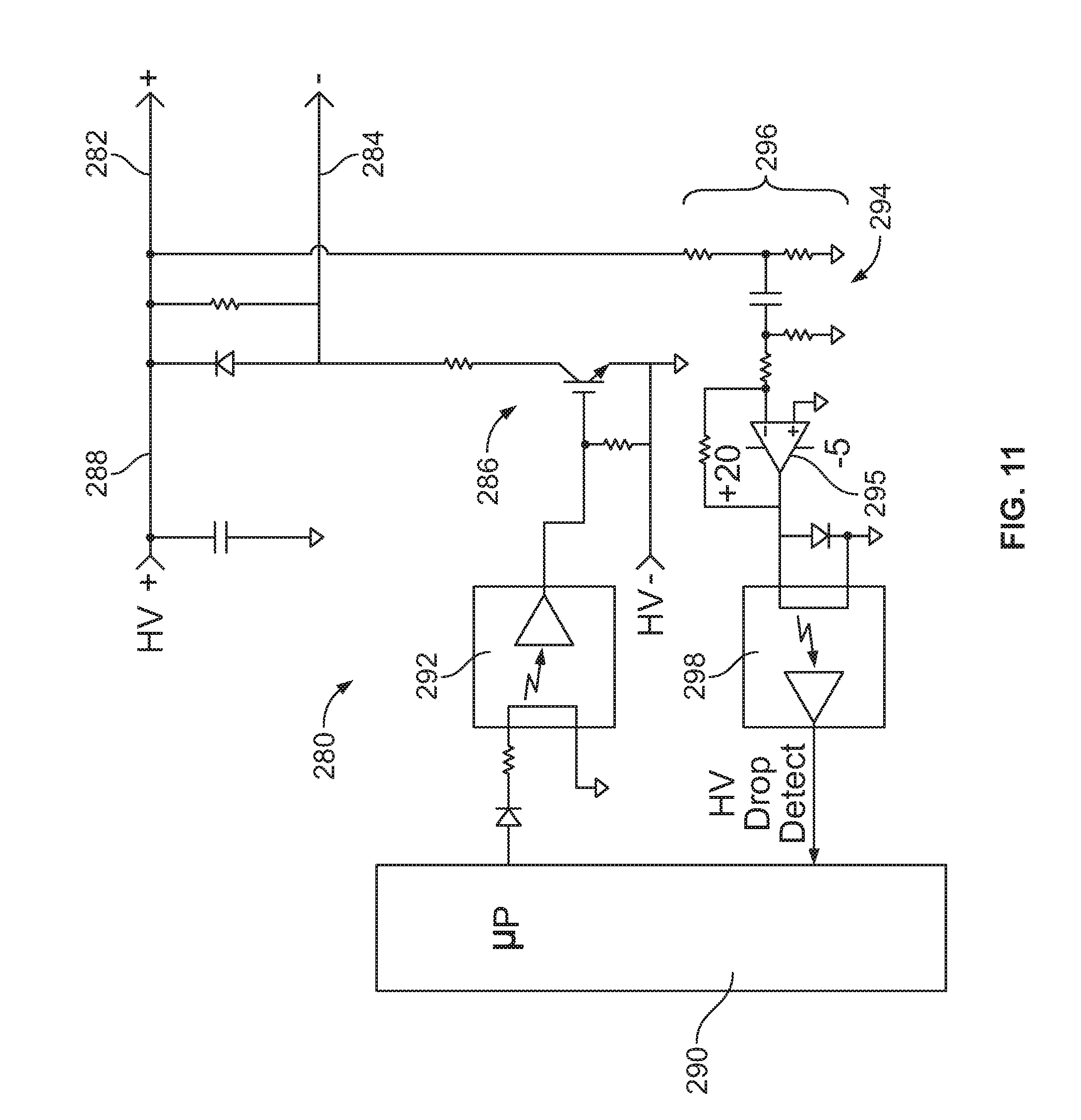
FIG. 11 is a schematic diagram of a power source 280 for use in an electrical arc shock wave angioplasty catheter according to a still further embodiment of the invention. Here the output switch of the power source is controlled in response to the voltage across the electrodes. More particularly, the power source provides a drive voltage that causes an initial high electrical voltage at an initial low current to be applied to the electrodes. The initial high electrical voltage causes an electrical arc to form across the first and second electrodes. The electrical arc causes a gas bubble within the liquid, a high current to flow through the first and second electrodes, a decrease in the initial high electrical voltage, and a mechanical shock wave within the balloon. The power source that provides the first and second electrodes with the drive voltage that creates the initial high electrical voltage at the initial current terminates the drive voltage in response to the decrease in the initial high electrical voltage. The power source may be arranged to terminate the drive voltage when the voltage across the electrodes decreases by more than a predetermined amount of voltage within less than a predetermined amount of time.
The power source 280 has an output terminal 282 that may be coupled to electrode 22 of FIG. 1 and an output terminal 284 that may be coupled to electrode 24 of FIG. 1. A switch circuit 286 selectively applies a high voltage on line 288 across the electrodes. A microprocessor 290, or other similar control circuitry, such as a gate array, controls the overall operation of the source 280. Again, a Field Programmable Gate Array (FPGA) may also be substituted for the microprocessor in a manner known in the art. The microprocessor 290 is coupled to the switch 286 by an optical driver 292. The switch includes a voltage sensor 294 that includes a voltage sensing resistive divider 296 that senses the output voltage. The divider is coupled to a capacitive coupled amplifier 295 that generates a signal that is applied to an optical isolator 298 when the voltage across the electrodes decreases by a predetermined amount within a predetermined amount of time to turn off the high voltage. For example, the voltage decrease required may be about 100 volts within about 0.1 microseconds or about 500 volts within about 0.5 microseconds.
In operation, the microprocessor 290 through the optical driver 292, causes the switch 286 to apply the high drive voltage (e.g., from about 1,500 V to about 4,000 V; about 3,000 V) to the electrodes 22 and 24. The output voltage sensed by the voltage sensing resistive divider 296 is monitored by the microprocessor 290 through the optical isolator 298. When the output voltage across the electrodes decreases by a predetermined amount within a predetermined amount of time as for example, by about 100 volts within about 0.1 microseconds or by about 500 volts within about 0.5 microseconds, the microprocessor 290 causes the application of the high voltage to be terminated. The forgoing occurs for each high voltage pulse applied to the electrodes 22 and 24. Each pulse creates a shock wave of consistent and useful intensity (i.e., such that the shock wave intensity is sufficient to crack a calcified lesion). Further, because the application of the high voltage is terminated early, the electrode material is preserved to lengthen the useful life of the electrodes.
FIG. 12 is a flow diagram illustrating a manner in which the power source of FIG. 11 may operate in accordance with a still further embodiment. The embodiment of FIG. 12 takes into account a fast response by the switch 286 to make sure that the output voltage is not terminated too early. This assures that a maximum output current and maximum intensity shock wave will be formed. In order to permit the maximum current to be reached a delay is timed extending from when the output voltage across the electrodes decreases by a predetermined amount within a predetermined amount of time. Again, for example, the predetermined voltage decrease and amount of time for the decrease may be about 100 volts within about 0.1 microseconds or about 500 volts within about 0.5 microseconds. The current threshold may be about fifty amperes. The delay timing is begun by the starting of a delay timer within the microprocessor 90. If the current is expected to be at a maximum 200 nanoseconds after the current reaches fifty amperes, and if it takes 100 nanoseconds for the high voltage switch to actually turn off after receiving a turn off signal, a delay of 100 nanoseconds should be timed from the 50 ampere sensing before a turn off signal is applied to the high voltage switch. Hence, a total time of 200 nanoseconds will pass after the current reaches 50 amperes and, as a result, will reach its maximum. As the current reaches its maximum, or shortly thereafter, the voltage applied to the electrodes will be terminated.
Referring now to the flow diagram 400 of FIG. 12, and also with reference to FIG. 11, the process begins with activity step 402 wherein a high drive voltage (e.g., from about 1,500 V to about 5,000 V, e.g., about 3,000 V) is applied to the output terminals 282 and 284 for application to the electrodes, for example, electrodes 22 and 24 (FIG. 1). At first, the voltage across the electrodes may be relatively high, e.g., from about 1,500 V to about 5,000 V, e.g., about 3,000 V. However, after a dwell time, the applied high voltage causes an electrical arc to begin to form between the electrodes. As the arc is formed, the voltage across the electrodes decreases rapidly. At decision block 404, the microprocessor 290 determines if the voltage decreases meets the predetermined voltage decrease and time criteria. When the criteria are met, the process advances to activity block 406 where the timing of the aforementioned delay time (x) is started. Next, in decision block 408, it is determined when the delay time has been timed. In accordance with this embodiment, the delay time (x) may be from about 0 ns to about 100 nanoseconds, e.g., 100 nanoseconds. When the delay time of 100 nanoseconds is timed, the process advances to activity block 410 wherein the process completes with a turn off signal being applied by the microprocessor 290 to the high voltage switch 286. The switch 286 will actually turn off a turn off time after the turn off signal is applied to the switch 286. If it takes 100 nanoseconds for the switch to turn off and since 100 nanoseconds are timed before the turn off signal is applied to the switch, 200 nanoseconds from the voltage decrease sensing will pass before the applied voltage to the electrodes is actually terminated. That provides sufficient time for the current to reach its maximum to generate the maximum intensity shock wave. The voltage application will be terminated as the current reaches maximum, or shortly thereafter.
While particular embodiments of the present invention have been shown and described, modifications may be made. It is therefore intended in the appended claims to cover all such changes and modifications which fall within the true spirit and scope of the invention as defined by those claims.
* * * * *
References
-
mouser.com/pdfdocs/bourns_gdt_whitepaper.pdf
-
healio.com/cardiac-vascular-intervention/peripheral/news/online/%7Bf96c1e20-b4a9-4167-bdb8-254e86a8182a%7D/shockwave-attracts-additional-investment-from-abiomed-has-ipo
-
citel.us/gas_discharge_tubes_overview.html
-
investors.com/news/technology/shockwave-medical-ipo-soars-trading
-
dicardiology.com/product/fda-clearslithoplasty-balloon-shatters-calcified-lesions-ultrasound
-
g3ynh.info/disch_tube/intro.html
-
cardiovascularnews.com/intravascular-lithotripsy-anovel-technology-for-treating-calcified-coronary-stenoses
-
pocketmagic.net/relaxation-oscillator-using-a-hydrogenthyratron
-
newsday.com/news/health/calcium-treatment-st-francis-hospital-1.27314331
-
shockwavemedical.com/technology/intravascular-lithotripsy-ivl/?country=Egypt
-
ti.com/lit/sg/slvt145r/slvt145r.pdf
D00000
D00001
D00002
D00003
D00004
D00005
D00006
D00007
XML
uspto.report is an independent third-party trademark research tool that is not affiliated, endorsed, or sponsored by the United States Patent and Trademark Office (USPTO) or any other governmental organization. The information provided by uspto.report is based on publicly available data at the time of writing and is intended for informational purposes only.
While we strive to provide accurate and up-to-date information, we do not guarantee the accuracy, completeness, reliability, or suitability of the information displayed on this site. The use of this site is at your own risk. Any reliance you place on such information is therefore strictly at your own risk.
All official trademark data, including owner information, should be verified by visiting the official USPTO website at www.uspto.gov. This site is not intended to replace professional legal advice and should not be used as a substitute for consulting with a legal professional who is knowledgeable about trademark law.