Linear magnetic drive transducer for ultrasound imaging
Weitzel , et al. Dec
U.S. patent number 10,517,569 [Application Number 13/890,906] was granted by the patent office on 2019-12-31 for linear magnetic drive transducer for ultrasound imaging. This patent grant is currently assigned to THE REGENTS OF THE UNIVERSITY OF MICHIGAN. The grantee listed for this patent is THE REGENTS OF THE UNIVERSITY OF MICHIGAN. Invention is credited to Robert Brook, Leo Koziol, Grant Kruger, Mainak Mitra, Jonathan Rubin, Brian Thelen, William Weitzel.


View All Diagrams
| United States Patent | 10,517,569 |
| Weitzel , et al. | December 31, 2019 |
Linear magnetic drive transducer for ultrasound imaging
Abstract
An ultrasound imaging system uses a magnetic linear motor driven ultrasound scanner, with accurate track and hold operation and/or other motion feedback, to scan a two dimensional or three dimensional area of a sample. The scanner is implemented in a low-power and low-bandwidth handheld device and is connected with a remote image processing system that receives raw data and performs full ultrasound image analysis and creation, allowing the handheld to be used for scanning, pre-processing, and display.
| Inventors: | Weitzel; William (Ypsilanti, MI), Kruger; Grant (Ann Arbor, MI), Thelen; Brian (Ann Arbor, MI), Rubin; Jonathan (Ann Arbor, MI), Koziol; Leo (Canton, MI), Brook; Robert (Canton, MI), Mitra; Mainak (Ann Arbor, MI) | ||||||||||
|---|---|---|---|---|---|---|---|---|---|---|---|
| Applicant: |
|
||||||||||
| Assignee: | THE REGENTS OF THE UNIVERSITY OF
MICHIGAN (Ann Arbor, MI) |
||||||||||
| Family ID: | 49551283 | ||||||||||
| Appl. No.: | 13/890,906 | ||||||||||
| Filed: | May 9, 2013 |
Prior Publication Data
| Document Identifier | Publication Date | |
|---|---|---|
| US 20130345566 A1 | Dec 26, 2013 | |
Related U.S. Patent Documents
| Application Number | Filing Date | Patent Number | Issue Date | ||
|---|---|---|---|---|---|
| 61645025 | May 9, 2012 | ||||
| Current U.S. Class: | 1/1 |
| Current CPC Class: | G01N 29/222 (20130101); A61B 8/4483 (20130101); A61B 8/461 (20130101); A61B 8/0891 (20130101); A61B 8/4427 (20130101); G01S 15/8945 (20130101); A61B 8/4461 (20130101); A61B 8/488 (20130101); A61B 8/4472 (20130101); G01S 7/52042 (20130101); A61B 8/483 (20130101); G01S 7/003 (20130101); G01S 7/52065 (20130101); G01S 15/8995 (20130101); A61B 8/56 (20130101); G01S 15/8915 (20130101) |
| Current International Class: | A61B 8/00 (20060101); A61B 8/08 (20060101); G01S 15/89 (20060101); G01N 29/22 (20060101); G01S 7/00 (20060101); G01S 7/52 (20060101) |
| Field of Search: | ;600/443,445 |
References Cited [Referenced By]
U.S. Patent Documents
| 3964296 | June 1976 | Matzuk |
| 4275597 | June 1981 | Quedens et al. |
| 4407293 | October 1983 | Suarez, Jr. et al. |
| 4457311 | July 1984 | Sorenson et al. |
| 4802487 | February 1989 | Martin et al. |
| 4858613 | August 1989 | Fry et al. |
| 4882934 | November 1989 | Leffert et al. |
| 4917096 | April 1990 | Englehart et al. |
| 4955365 | September 1990 | Fry et al. |
| 4974211 | November 1990 | Corl |
| 5003238 | March 1991 | Lum et al. |
| 5036855 | August 1991 | Fry et al. |
| 5159931 | November 1992 | Pini |
| 5178150 | January 1993 | Silverstein et al. |
| 5181514 | January 1993 | Solomon et al. |
| 5211176 | May 1993 | Ishiguro et al. |
| 5353796 | October 1994 | Schroeder et al. |
| 5361768 | November 1994 | Webler et al. |
| 5400790 | March 1995 | Pohan et al. |
| 5465724 | November 1995 | Sliwa, Jr. et al. |
| 5469852 | November 1995 | Nakamura et al. |
| 5485846 | January 1996 | Webler et al. |
| 5562096 | October 1996 | Hossack et al. |
| 5572448 | November 1996 | Judell |
| 5592942 | January 1997 | Webler et al. |
| 5603326 | February 1997 | Richter |
| 5605154 | February 1997 | Ries et al. |
| 5630417 | May 1997 | Petersen et al. |
| 5704898 | January 1998 | Kokish |
| 5720285 | February 1998 | Petersen |
| 5722412 | March 1998 | Pflugrath et al. |
| 5755571 | May 1998 | Companion |
| 5759153 | June 1998 | Webler et al. |
| 5820564 | October 1998 | Slayton et al. |
| 5836880 | November 1998 | Pratt |
| 5848969 | December 1998 | Panescu et al. |
| 5904651 | May 1999 | Swanson et al. |
| 5908445 | June 1999 | Whayne et al. |
| 5967984 | October 1999 | Chu et al. |
| 5983123 | November 1999 | Shmulewitz |
| 5999167 | December 1999 | Marsh et al. |
| 6004272 | December 1999 | Barry et al. |
| 6036646 | March 2000 | Barthe et al. |
| 6049159 | April 2000 | Barthe et al. |
| 6050943 | April 2000 | Slayton et al. |
| 6099474 | August 2000 | Solek |
| 6108439 | August 2000 | Ishiguro |
| 6110121 | August 2000 | Lenker |
| 6117101 | September 2000 | Diederich et al. |
| 6120452 | September 2000 | Barthe et al. |
| 6126600 | October 2000 | Oxaal et al. |
| 6139500 | October 2000 | Clark |
| 6167765 | January 2001 | Weitzel |
| 6186864 | February 2001 | Fisher, Jr. et al. |
| 6213948 | April 2001 | Barthe et al. |
| 6409669 | June 2002 | Hager et al. |
| 6409672 | June 2002 | Webler et al. |
| 6425870 | July 2002 | Flesch |
| 6440071 | August 2002 | Slayton et al. |
| 6500121 | December 2002 | Slayton et al. |
| 6527731 | March 2003 | Weiss et al. |
| 6540679 | April 2003 | Slayton et al. |
| 6540681 | April 2003 | Cheng |
| 6561982 | May 2003 | Greppi et al. |
| 6572548 | June 2003 | Cerofolini |
| 6574499 | June 2003 | Dines et al. |
| 6575927 | June 2003 | Weitzel et al. |
| 6582381 | June 2003 | Yehezkeli et al. |
| 6585666 | July 2003 | Suh et al. |
| 6589174 | July 2003 | Chopra et al. |
| 6592520 | July 2003 | Peszynski et al. |
| 6613005 | September 2003 | Friedman et al. |
| 6623430 | September 2003 | Slayton et al. |
| 6623433 | September 2003 | Webler et al. |
| 6659955 | December 2003 | Marian, Jr. |
| 6679845 | January 2004 | Ritter et al. |
| 6709414 | March 2004 | Weitzel et al. |
| 6776758 | August 2004 | Peszynski et al. |
| 6780153 | August 2004 | Angelsen et al. |
| 6872180 | March 2005 | Reinhardt et al. |
| 6996432 | February 2006 | Ostrovsky et al. |
| 7022080 | April 2006 | Marian, Jr. |
| 7100449 | September 2006 | Busch et al. |
| 7142905 | November 2006 | Slayton et al. |
| 7214230 | May 2007 | Brock et al. |
| 7229411 | June 2007 | Slayton et al. |
| 7302851 | December 2007 | Czerw et al. |
| 7359691 | April 2008 | Adachi et al. |
| 7393325 | July 2008 | Barthe et al. |
| 7484412 | February 2009 | Hart et al. |
| 7491172 | February 2009 | Bruestle |
| 7494469 | February 2009 | Bruestle |
| 7497120 | March 2009 | Schneider et al. |
| 7524289 | April 2009 | Lenker |
| 7530271 | May 2009 | Busch et al. |
| 7530958 | May 2009 | Slayton et al. |
| 7554026 | June 2009 | de Moraes |
| 7568391 | August 2009 | Schneider et al. |
| 7569015 | August 2009 | Donaldson et al. |
| 7571336 | August 2009 | Barthe et al. |
| 7572223 | August 2009 | Donaldson |
| 7580762 | August 2009 | Abrams et al. |
| 7591787 | September 2009 | Tortoli |
| 7652259 | January 2010 | Kimchy et al. |
| 7666143 | February 2010 | Wilser et al. |
| 7678056 | March 2010 | Wilser et al. |
| 7691060 | April 2010 | Angelsen et al. |
| 7727152 | June 2010 | Qin et al. |
| 7740587 | June 2010 | Hiltawsky |
| 7771360 | August 2010 | Johnson et al. |
| 7781973 | August 2010 | Miyake et al. |
| 7801591 | September 2010 | Shusterman |
| 7824348 | November 2010 | Barthe et al. |
| 7914452 | March 2011 | Hartley et al. |
| 7914453 | March 2011 | Slayton et al. |
| 7931594 | April 2011 | Hirsh |
| 7987303 | July 2011 | Bartlett |
| 7989177 | August 2011 | Bystryak et al. |
| 8038619 | October 2011 | Steinbacher |
| 8038622 | October 2011 | Abraham |
| 8052609 | November 2011 | Harhen |
| 8057395 | November 2011 | Lenker |
| 8057397 | November 2011 | Li et al. |
| 8070685 | December 2011 | Harhen et al. |
| 8090065 | January 2012 | Gabrielson et al. |
| 8147413 | April 2012 | Abraham |
| 8147414 | April 2012 | Abraham |
| 8157741 | April 2012 | Hirota |
| 8166332 | April 2012 | Barthe et al. |
| 8211025 | July 2012 | Donaldson et al. |
| 8220334 | July 2012 | Klessel et al. |
| 8235903 | August 2012 | Abraham |
| 8235909 | August 2012 | Barthe et al. |
| 8312771 | November 2012 | Randall et al. |
| 8317711 | November 2012 | Dala-Krishna |
| 8323199 | December 2012 | Salcudean et al. |
| 8356518 | January 2013 | Alleyne et al. |
| 8382671 | February 2013 | Anthony et al. |
| 8409097 | April 2013 | Slayton et al. |
| 8409102 | April 2013 | Griffin et al. |
| 2001/0020126 | September 2001 | Swanson et al. |
| 2001/0029328 | October 2001 | Crowley |
| 2002/0016545 | February 2002 | Quistgaard et al. |
| 2002/0099356 | July 2002 | Unger et al. |
| 2002/0103432 | August 2002 | Kawchuk |
| 2002/0111548 | August 2002 | Swanson et al. |
| 2002/0117904 | August 2002 | Godkin |
| 2003/0011362 | January 2003 | Gohlsch et al. |
| 2003/0045815 | March 2003 | Ombrellaro |
| 2003/0055338 | March 2003 | Steininger et al. |
| 2003/0095692 | May 2003 | Mundy et al. |
| 2003/0135135 | July 2003 | Miwa |
| 2003/0167004 | September 2003 | Dines |
| 2003/0195510 | October 2003 | Schaer |
| 2004/0073118 | April 2004 | Peszynski et al. |
| 2004/0097836 | May 2004 | Ombrellaro |
| 2004/0136570 | July 2004 | Ullman et al. |
| 2004/0147840 | July 2004 | Duggirala et al. |
| 2004/0215490 | October 2004 | Duchon et al. |
| 2004/0226645 | November 2004 | Owen |
| 2004/0254466 | December 2004 | Boner et al. |
| 2005/0015011 | January 2005 | Liard et al. |
| 2005/0049498 | March 2005 | Roche et al. |
| 2005/0054923 | March 2005 | Pan |
| 2005/0054958 | March 2005 | Hoffmann |
| 2005/0102161 | May 2005 | Kalthoff et al. |
| 2005/0126291 | June 2005 | Czerw et al. |
| 2005/0150740 | July 2005 | Finkenzeller et al. |
| 2005/0154311 | July 2005 | Bruestle |
| 2005/0203396 | September 2005 | Angelsen et al. |
| 2005/0203416 | September 2005 | Angelsen et al. |
| 2005/0251035 | November 2005 | Wong et al. |
| 2005/0255239 | November 2005 | Zhu et al. |
| 2005/0265267 | December 2005 | Hwang |
| 2005/0288587 | December 2005 | Roh et al. |
| 2006/0045286 | March 2006 | Abrams et al. |
| 2006/0085049 | April 2006 | Cory et al. |
| 2006/0100529 | May 2006 | Rueckmann et al. |
| 2006/0173344 | August 2006 | Marian et al. |
| 2006/0173348 | August 2006 | Wilser et al. |
| 2006/0241423 | October 2006 | Anderson et al. |
| 2006/0241452 | October 2006 | Cerofolini |
| 2006/0241455 | October 2006 | Shvarts |
| 2006/0275171 | December 2006 | Younts |
| 2007/0011836 | January 2007 | Brewer et al. |
| 2007/0013269 | January 2007 | Huang |
| 2007/0043585 | February 2007 | Matos |
| 2007/0062290 | March 2007 | Roh et al. |
| 2007/0088213 | April 2007 | Poland |
| 2007/0096568 | May 2007 | Patt |
| 2007/0106143 | May 2007 | Flaherty |
| 2007/0156126 | July 2007 | Flaherty |
| 2007/0167813 | July 2007 | Lee et al. |
| 2007/0167821 | July 2007 | Lee et al. |
| 2007/0167823 | July 2007 | Lee et al. |
| 2007/0167824 | July 2007 | Lee et al. |
| 2007/0167825 | July 2007 | Lee et al. |
| 2007/0167826 | July 2007 | Lee et al. |
| 2007/0197954 | August 2007 | Keenan |
| 2007/0208253 | September 2007 | Slayton et al. |
| 2007/0232921 | October 2007 | Lee |
| 2007/0239075 | October 2007 | Rosenberg et al. |
| 2007/0270781 | November 2007 | Burgermeister et al. |
| 2007/0276240 | November 2007 | Rosner et al. |
| 2007/0277596 | December 2007 | Kim et al. |
| 2008/0014627 | January 2008 | Merchant et al. |
| 2008/0021317 | January 2008 | Sumanaweera |
| 2008/0027327 | January 2008 | Wilser et al. |
| 2008/0086054 | April 2008 | Slayton et al. |
| 2008/0134813 | June 2008 | Petetin |
| 2008/0136973 | June 2008 | Park |
| 2008/0167555 | July 2008 | Qian et al. |
| 2008/0269647 | October 2008 | Brunsveld Van Hulten |
| 2008/0281206 | November 2008 | Bartlett et al. |
| 2008/0287793 | November 2008 | Hoffmann |
| 2008/0287797 | November 2008 | Lee et al. |
| 2008/0287860 | November 2008 | Tgavalekos et al. |
| 2008/0300490 | December 2008 | Chiang et al. |
| 2009/0036780 | February 2009 | Abraham |
| 2009/0038315 | February 2009 | Johnson |
| 2009/0043206 | February 2009 | Towfiq et al. |
| 2009/0105597 | April 2009 | Abraham |
| 2009/0118620 | May 2009 | Tgavalekos et al. |
| 2009/0171185 | July 2009 | Chou et al. |
| 2009/0171217 | July 2009 | Kim et al. |
| 2009/0171252 | July 2009 | Bockenstedt et al. |
| 2009/0171255 | July 2009 | Rybyanets et al. |
| 2009/0177092 | July 2009 | Riechers et al. |
| 2009/0192389 | July 2009 | Eilers et al. |
| 2009/0216159 | August 2009 | Slayton et al. |
| 2009/0221917 | September 2009 | Southern |
| 2009/0247879 | October 2009 | Angelsen et al. |
| 2009/0254134 | October 2009 | Nikolov et al. |
| 2009/0281422 | November 2009 | Salama et al. |
| 2009/0299193 | December 2009 | Haftman et al. |
| 2009/0307328 | December 2009 | Nuttall et al. |
| 2009/0312638 | December 2009 | Bartlett |
| 2009/0312639 | December 2009 | Medlin et al. |
| 2009/0316854 | December 2009 | Ismail et al. |
| 2009/0318808 | December 2009 | Brader |
| 2009/0326341 | December 2009 | Furlan |
| 2010/0036240 | February 2010 | Ismail et al. |
| 2010/0036258 | February 2010 | Dietz et al. |
| 2010/0049099 | February 2010 | Thapliyal et al. |
| 2010/0056858 | March 2010 | Mokelke et al. |
| 2010/0056912 | March 2010 | Urness et al. |
| 2010/0056956 | March 2010 | Dufresne et al. |
| 2010/0063398 | March 2010 | Halmann |
| 2010/0076789 | March 2010 | Pan |
| 2010/0125192 | May 2010 | Chopra et al. |
| 2010/0152590 | June 2010 | Moore et al. |
| 2010/0174185 | July 2010 | Wang et al. |
| 2010/0174189 | July 2010 | Abraham |
| 2010/0198081 | August 2010 | Hanlin et al. |
| 2010/0217125 | August 2010 | Kadokura |
| 2010/0217128 | August 2010 | Betts |
| 2010/0226555 | September 2010 | Sandstrom et al. |
| 2010/0228122 | September 2010 | Keenan et al. |
| 2010/0249602 | September 2010 | Buckley et al. |
| 2010/0256502 | October 2010 | Buckley et al. |
| 2010/0262007 | October 2010 | Medlin et al. |
| 2010/0262160 | October 2010 | Boyden et al. |
| 2010/0262239 | October 2010 | Boyden et al. |
| 2010/0274100 | October 2010 | Behar et al. |
| 2010/0280420 | November 2010 | Barthe et al. |
| 2010/0286521 | November 2010 | Betts |
| 2010/0298711 | November 2010 | Pedersen et al. |
| 2010/0305443 | December 2010 | Bartlett et al. |
| 2010/0324418 | December 2010 | El-Aklouk |
| 2010/0324423 | December 2010 | El-Aklouk et al. |
| 2011/0034209 | February 2011 | Rubinsky et al. |
| 2011/0054292 | March 2011 | Hirson et al. |
| 2011/0054296 | March 2011 | McCarthy et al. |
| 2011/0055447 | March 2011 | Costa |
| 2011/0080120 | April 2011 | Talstra et al. |
| 2011/0092781 | April 2011 | Gertner |
| 2011/0098571 | April 2011 | Medlin et al. |
| 2011/0098572 | April 2011 | Chen et al. |
| 2011/0105907 | May 2011 | Oakley et al. |
| 2011/0125022 | May 2011 | Lazebnik |
| 2011/0166455 | July 2011 | Cully et al. |
| 2011/0172541 | July 2011 | Anthony et al. |
| 2011/0196267 | August 2011 | Mishelevich |
| 2011/0201914 | August 2011 | Wang et al. |
| 2011/0210821 | September 2011 | Gehin |
| 2011/0237955 | September 2011 | Dietz et al. |
| 2011/0238085 | September 2011 | Berzak et al. |
| 2011/0248820 | October 2011 | Gehin |
| 2011/0270138 | November 2011 | Mishelevich |
| 2011/0270797 | November 2011 | Adams et al. |
| 2011/0301508 | December 2011 | Sethuraman et al. |
| 2011/0306886 | December 2011 | Daft et al. |
| 2011/0319760 | December 2011 | Cerofolini et al. |
| 2011/0319765 | December 2011 | Gertner et al. |
| 2011/0320143 | December 2011 | Hopkins |
| 2012/0022379 | January 2012 | Gubbini et al. |
| 2012/0022409 | January 2012 | Gertner et al. |
| 2012/0029303 | February 2012 | Shaya |
| 2012/0046548 | February 2012 | Hao et al. |
| 2012/0046553 | February 2012 | Buckley et al. |
| 2012/0053468 | March 2012 | Griffin et al. |
| 2012/0089029 | April 2012 | Harhen |
| 2012/0095347 | April 2012 | Adam et al. |
| 2012/0109018 | May 2012 | Gertner et al. |
| 2012/0172706 | July 2012 | Salminen |
| 2012/0203098 | August 2012 | Raju et al. |
| 2012/0203104 | August 2012 | Urness et al. |
| 2012/0209118 | August 2012 | Warnking |
| 2012/0245466 | September 2012 | Ganguly |
| 2012/0253239 | October 2012 | Gertner et al. |
| 2012/0271168 | October 2012 | Radojicic |
| 2012/0272738 | November 2012 | Klessel et al. |
| 2012/0289869 | November 2012 | Tyler |
| 2012/0296899 | November 2012 | Adams |
| 2013/0024704 | January 2013 | Barthe et al. |
| 2013/0066208 | March 2013 | Barthe et al. |
Other References
|
Nippon Pulse America, "S040 Linear Shaft Motor for Small-Scale High Precision", Aug. 9, 2011, Nippon Pulse website. cited by examiner . International Search Report and Written Opinion, corresponding International Application No. PCT/US2013/040381, dated Sep. 24, 2013. cited by applicant . Aschkenasy et al., Unsupervised image classification of medical ultrasound data by multiresolution elastic registration, Ultrasound Med. Biol., 32(7):1047-54 (2006). cited by applicant . Biswas et al., Venous elastography: validation of a novel high-resolution ultrasound method for measuring vein compliance using finite element analysis, Semin. Dial., 23(1):105-9 (2010). cited by applicant . Castellano et al., Texture analysis of medical images, Clin. Radiol., 59(12):1061-9 (2004). cited by applicant . Garg et al., Embolic strokes after peripherally inserted central catheter placement, Ann. Vasc. Surg., 24:1133-6 (2010). cited by applicant . Guo et al., A novel approach to speckle reduction in ultrasound imaging, Ultrasound Med. Biol., 35(4):628-40 (2009). cited by applicant . Haas, Clinical review: vascular access for fluid infusion in children, Crit. Care, 8(6):478-84 (2004). cited by applicant . Kim et al., Local nonlinear arterial elastic modulus reconstruction from in-vivo strain imaging and PWV, Proc. IEEE Intl. Ultrasonics Symposium, pp. 728-731 (2006). cited by applicant . Kim et al., Dual arterial elastic modulus reconstructions from in-vivo strain imaging and PWV, Proc. IEEE Intl. Ultrasonics Symposium, 1:377-80 (2005). cited by applicant . Matsushima et al., Bedside ultrasound can safely eliminate the need for chest radiographs after central venous catheter placement: CVC sono in the surgical ICU (SICU), J. Surg. Res., 163(1):155-61 (2010). cited by applicant . Nieuwstadt et al., Microfluidic particle sorting utilizing inertial lift force, Biomed. Microdevices, 13(1):97-105 (2011). cited by applicant . Oakley et al., Ultrasound-assisted peripheral vascular access in a paediatric ED, Emerg. Med. Australas., 22(2):166-70 (2010). cited by applicant . Park et al., Arterial elasticity imaging: comparison of finite-element analysis models with high-resolution ultrasound speckle tracking, Cardiovasc. Ultrasound, 8:22 (2010). cited by applicant . Patel et al., Characterization of vascular strain during in-vitro angioplasty with high-resolution ultrasound speckle tracking, Theor. Biol. Med. Model., 7:36 (2010). cited by applicant . Qamar et al., Evolution of acoustically vaporized microdroplets in gas embolotherapy, J. Biomech. Eng., 134(3):031010 (2012). cited by applicant . Reeves et al., Recent trends in central venous catheter placement: a comparison of interventional radiology with other specialties, J. Vasc. Interv. Radiol., 12(10:1211-4 (2001). cited by applicant . Rubin et al., Sonographic elasticity imaging of acute and chronic deep venous thrombosis in humans, J. Ultrasound Med., 25(9):1179-86 (2006). cited by applicant . Sette et al., First: patient safety, second: patient safety, J. Electrocardiol., 44(3):389-90 (2011). cited by applicant . Skippen et al., Ultrasound guidance for central vascular access in the pediatric emergency department, Pediatr. Emerg. Care, 23(3):203-7 (2007). cited by applicant . Stippel et al., A tissue-specific adaptive texture filter for medical ultrasound images, Ultrasound Med. Biol., 31(9):1211-23 (2005). cited by applicant . Tsantis et al., Development of a support vector machine-based image analysis system for assessing the thyroid nodule malignancy risk on ultrasound, Ultrasound Med. Biol., 31(11):1451-9 (2005). cited by applicant . Vo et al., Techniques in vascular and interventional radiology: pediatric central venous access, Tech. Vasc. Interv. Radiol., 13(4):250-7 (2010). cited by applicant . Weitzel et al., High-resolution ultrasound elasticity imaging to evaluate dialysis fistula stenosis, Semin. Dial., 22(1):84-9 (2009). cited by applicant . Weitzel, Preoperative hemodialysis fistula evaluation: angiography, ultrasonography and other studies, are they useful?, Contrib. Nephrol., 161:23-9 (2008). cited by applicant . Weitzel et al., High-resolution ultrasound speckle tracking may detect vascular mechanical wall changes in peripheral artery bypass vein grafts, Ann. Vasc. Surg., 23(2):201-6 (2009). cited by applicant . Weitzel et al., Renal advances in ultrasound elasticity imaging: measuring the compliance of arteries and kidneys in end-stage renal disease, Blood Purif., 23(1):10-7 (2005). cited by applicant . Weitzel et al., Feasibility of applying ultrasound strain imaging to detect renal transplant chronic allograft nephropathy, Kidney Int., 65(2):733-6 (2004). cited by applicant . Xie et al., Correspondence of ultrasound elasticity imaging to direct mechanical measurement in aging DVT in rats, Ultrasound Med. Biol., 31(10):1351-9 (2005). cited by applicant . Ye et al., Microbubble expansion in a flexible tube, J. Biomech. Eng., 128(4):554-63 (2006). cited by applicant. |
Primary Examiner: Rozanski; Michael T
Attorney, Agent or Firm: Marshall, Gerstein & Borun LLP
Government Interests
STATEMENT REGARDING FEDERALLY SPONSORED RESEARCH OR DEVELOPMENT
This invention was made with government support under HL101881 awarded by the National Institutes of Health. The government has certain rights in the invention.
Parent Case Text
CROSS-REFERENCE TO RELATED APPLICATIONS
This application claims the benefit of U.S. Application Ser. No. 61/645,025, filed May 9, 2012, entitled "Linear Magnetic Drive Transducer For Ultrasound Imaging," which is hereby incorporated by reference in its entirety.
Claims
The invention claimed is:
1. An ultrasound scanning device for providing real-time two-dimensional scan data of a sample area, the scanning device comprising: a magnetic drive assembly defining a first scanning direction of freedom for moving a scan head of the magnetic drive assembly along a curvilinear path, the magnetic drive assembly including a housing, the housing containing a fluid and maintaining the fluid within an area defined by a housing base and a housing cap; a guide rail structure comprising a plurality of guide rails encapsulated by the housing, the guide rail structure defining the curvilinear path; a plurality of fixed permanent magnets, each fixed permanent magnet of the plurality of permanent magnets magnetizing at least one guide rail of the plurality of guide rails and each fixed permanent magnet of the plurality of permanent magnets located outside the curvilinear path of the scan head; and the scan head of the magnetic drive assembly, the scan head encapsulated by the housing and positioned to move within the fluid in the housing and comprising a coil, an ultrasound transducer, and a position sensor, and the scan head moveable on the guide rail structure between the plurality of permanent magnets which are fixed relative to that movement and wherein the scan head is movable in response to drive signals provided to the magnetic drive assembly, the ultrasound transducer providing ultrasound scanning over a first scan plane corresponding to the sample area and extending below a surface contact area for the scanning device.
2. The ultrasound scanning device of claim 1, wherein the magnetic drive assembly defines a second scanning direction of freedom, different than the first scanning direction of freedom, to scan within the first scan plane.
3. The ultrasound scanning device of claim 1, wherein the ultrasound transducer defines a second scanning direction of freedom, different than the first scanning direction of freedom, to scan within the first scan plane.
4. The ultrasound scanning device of claim 2 or 3, wherein the second scanning direction of freedom is scanned electrically or mechanically.
5. The ultrasound scanning device of claim 4, a magnetic drive assembly controller is to scan the ultrasound transducer in the first scan plane to effect one of either Doppler velocity data, pulse-echo ultrasound data for radio-frequency tracking, or B mode data over the first scan plane.
6. The ultrasound scanning device of claim 1, wherein the magnetic drive assembly defines a second scanning direction of freedom, different than the first scanning direction of freedom, to scan within a second plane, different from the first scan plane for obtaining three-dimensional scan data.
7. The ultrasound scanning device of claim 1, wherein the ultrasound transducer defines a second scanning direction of freedom, different than the first scanning direction of freedom, to scan within a second plane, different from the first scan plane for obtaining three-dimensional scan data.
8. The scanning device of claim 1, wherein the magnetic drive assembly comprises two fixed permanent magnets positioned on opposite sides of the guide rail structure and having opposing poles.
9. The scanning device of claim 8, wherein at least another guide rail of the plurality of guide rails is a passive guide rail, wherein the passive guide rail provides support and is not magnetized by the plurality of fixed permanent magnets.
10. The scanning device of claim 1, wherein the ultrasound transducer is a piezoelectric transducer.
11. The scanning device of claim 1, wherein the ultrasound transducer is a Capacitive Micromachined Ultrasonic Transducers (CMUT) transducer.
12. The scanning device of claim 1, wherein the ultrasound transducer is a single element transducer.
13. The scanning device of claim 1, wherein the ultrasound transducer is a multiple-element transducer, wherein each of a plurality of elements is aligned along the curvilinear path during scanning.
14. The scanning device of claim 1, wherein the ultrasound transducer is mounted on a swivel base of the scan head or another base having a second scanning direction of freedom different than the first scanning direction of freedom, such that the ultrasound transducer is aligned for scanning along the curvilinear path during scanning and has an orientation that changes in response to the swivel base or another base to scan at different angles during scanning along the curvilinear path, wherein the orientation changes are either actively induced or passively induced.
15. The scanning device of claim 1, wherein a sensor of a magnetic drive assembly controller determines position and orientation of the ultrasound transducer.
16. The scanning device of claim 1, wherein a sensor of a magnetic drive assembly controller determines position by sensing a physical characteristic of the ultrasound transducer or the magnetic drive assembly.
17. The scanning device of claim 16, wherein the physical characteristic is a physical alteration in the magnetic drive assembly performance resulting from scanning the ultrasound transducer.
18. The scanning device of claim 16, wherein the physical characteristic is a coordinate of the ultrasound transducer or the magnetic drive assembly.
19. The scanning device of claim 16, wherein the physical characteristic is a force generated by the ultrasound transducer or the magnetic drive assembly, a velocity of the scanning of the ultrasound transducer, or an acceleration of the scanning of the ultrasound transducer.
20. The scanning device of claim 1, wherein a sensor of a magnetic drive assembly controller determines position by sensing an electrical signal characteristic of the ultrasound transducer or the magnetic drive assembly.
21. The scanning device of claim 20, wherein the electrical signal characteristic is one or more of a drive current supplied to the magnetic drive assembly, a drive voltage supplied to the magnetic drive assembly, a voltage differential signal for the magnetic drive assembly, signal strength required to the ultrasound transducer during scanning, and optical encoder information.
22. The scanning device of claim 1, wherein a magnetic drive controller employs a rule-based control scheme.
23. The scanning device of claim 1, wherein a magnetic drive controller employs a velocity control scheme.
24. The scanning device of claim 1, wherein a magnetic drive controller employs a positioning control scheme.
25. The scanning device of claim 1, wherein a magnetic drive controller employs a frame rate control scheme.
26. The scanning device of claim 1, wherein a magnetic drive controller employs one or more of a proportional-integral-derivative feedback control scheme, a pole placement control scheme, a sliding mode control scheme, an adaptive control through recursive least squares parameter estimation scheme, a Luenberger observer scheme, a Kalman filter scheme, an extended Kalman filter scheme, and an unscented Kalman filter scheme.
27. The scanning device of claim 1, wherein a magnetic drive controller includes a feedback control for ultrasound transducer positioning.
28. The scanning device of claim 27, wherein the feedback control comprises a sample and hold controller for compensating against operator movement of the scanning device during operation.
29. The scanning device of claim 28, wherein the sample and hold controller compensates against operator movement using an edge integrity algorithm.
30. The scanning device of claim 28, wherein the sample and hold controller provides real-time self registration of the two-dimensional scan data.
31. The scanning device of claim 1, wherein the scanning device is a low-profile wearable device.
32. The scanning device of claim 1, wherein the scanning device is a low-profile wrist mountable wearable device.
33. The scanning device of claim 1, wherein a controller of the magnetic drive assembly further utilizes sensed data supplied from the ultrasound transducer to provide a control for the drive signals sent to the magnetic drive assembly.
Description
FIELD OF THE INVENTION
The invention relates generally to ultrasound imaging devices and, more particularly, to linear actuator-based ultrasound devices.
BACKGROUND
Ultrasound imaging has been a core technology used in the detection and treatment of many diseases and injuries. Ultrasound imagers use high-frequency sound waves to view soft tissues such as blood vessels, muscles, and internal organs, in real-time. The transducer sends out high-frequency sound waves that reflect off of body structures, where the returning sound waves, or echoes, are displayed as an image on a monitor, where that image is formed based on the frequency and strength (amplitude) of the sound signal and the time it takes to return from the patient to the transducer. Ultrasound imagers are able to measure effects such as tissue movement or displacement and blood flow. Indeed, measuring blood vessel geometry and blood flow dynamics in vessels, such as the carotid artery, as a function of time, is considered key to cardiovascular (CV) disease identification. Another common intended application is use for procedure guidance, in particular vascular (venous, central venous, or arterial) cannulation for the introduction of device, tubes, cannulas or catheters for introducing medications or other therapeutic agents into blood vessels. Conventional ultrasound imagers use a probe with transducer array that is placed against the skin and is connected to a hand-carried (or table mounted) scanner device for signal processing.
Generally speaking, current probe-based ultrasound systems are expensive array transducer devices that employ a large array of transducer elements used to scan an ultrasound beam over an area of interest. The arrays are typically one- or two-dimensional structures formed of 64, 128, or more elements, that provide scanning over a large sample area coinciding with the size of the array. The transducers arrays are wire-coupled to an ultrasound imaging station that includes a display, input keyboard, processing machine, typically housed on a moveable frame (cart based), carry case (hand carried), or desktop machine. Recently, some have proposed what is being called a handheld (as opposed to hand carried) diagnostic ultrasound imaging device. The system is pocket-sized, incorporating a miniature display and signal processing system, connected to an ultrasound probe through a wired connection. As the probes are physically moved across the patient, ultrasound data is communicated directly to the display and processing devices for real-time imaging. The devices are small, but still cumbersome in that the operator (e.g., physician, pharmacist, or other health care provider) hold and scan the probe with one hand and hold the display/processing unit in the other hand. This can make it difficult to perform certain procedures that require the use of another hand. The result is that the ultrasound image is not always easily kept within the field of view of the operator; and, either way, the operator is limited in where they can position the display because it must be within their visual range to discern important details in the image, should ideally be within the working area of the procedure, and must be tethered to the ultrasound probe. Some have proposed modifications to such devices, such as, a tethered interface that uses a removable connection, including a docking station; but the need to control the operation of the probe still requires tethering during operation. Furthermore the devices are expensive, in large part because all image processing is performed on the portable device, which requires expensive signal processing circuitry and the associated programming.
SUMMARY OF THE INVENTION
In contrast to the conventional systems, the present application describes a low-cost, high-performance compact ultrasound imaging system able to meet the clinical point-of-care needs across various applications, such as central venous catheter (CVC) placement or assessment of stenosis of the carotid arteries based upon consensus practice criteria guidelines. The imaging system uses innovative engineering design, accurate track and hold, low-power and low-bandwidth analog to digital converters, a rectilinear or curvilinear electro-magnetic transducer drive system with motion feedback, and distributed intelligent signal processing architecture to realize a high performance ultrasound imager at low manufacturing costs.
The systems described herein employ a compact and economically-designed ultrasound transducer capable of a variety of functions, including ultrasound imaging, flow measurement, distensibility measurement, elasticity measurement, position measurement, or any number of other physical attributes of a fluid vessel, tissue, or organ. Scanned data may be used to form one-, two-dimensional (2D), three-dimensional (3D) or four-dimensional (4D) images of a sample area and in real-time.
In some examples, the scanning device includes magnetic drive assembly that scans an ultrasound transducer element along a linear path. As used herein, the term "linear path" refers to a rectilinear path, curvilinear path, or some combination of both.
In some examples, the scanning device is configured in a closed-loop control configuration. A magnetic drive controller is not only able to control scanning of the ultrasound transducer, but at the same time measure physical or electrical or optical characteristics of the magnetic drive or ultrasound transducer in a feedback manner to allow for more stable, more accurate scanning. Using a closed-loop configuration on the scanning device allows the overall system to more accurately measure certain parameters that are traditionally too difficult to measure without expensive processing equipment, parameters such as elasticity and shear adjustment.
The scanning device is part of a distributed wireless imaging system, in which a remote imaging system, such as a server or server cluster (local or distributed), is configured to receive the pre-processed scan data and perform the computationally-intensive elasticity, wall shear velocity, motion tracking (including speckle tracking for accurate motion estimation and edge detection), 3D/4D image registration, etc. operations to produce ultrasound image data that may be sent back to the scanning device for display to the operator. The scanning devices may be modular and deployed in existing ultrasound imaging processing systems. For example, the scanning devices may include wireless transceivers for communications with a remote imaging system. The modular nature is also facilitated by the front-end image processing and operator motion compensation of the magnetic drive controller. In any event, the techniques may be deployed in existing or new distributed processing configurations.
The servers may provide remote access to the processed ultrasound data via standard networking protocols, such as those supporting streaming video, audio or the display of fixed images. Commonly available devices, such as tablets, smart phones, or notebooks, etc. can be used to access and view or replay in real-time or at varying speeds the ultrasound data. This would allow the display, acquisition and processing of the ultrasound data to be spatially distributed, if required.
The server may store the raw data streams and higher-level modules will be provided to perform user-customizable analysis of the RF data, so that the image display can be adapted to provide the best rendering of the data for diagnostic use.
In some examples, additional sensors, such as accelerometers or optical scanners (e.g. such as those in an optical computer mouse) may be integrated with the magnetic drive to track the gross motion of the overall transducer assembly to provide additional information to aid 3D/4D image registration (tracking the trajectory of the device as it is moved over the surface of the skin).
In other examples, the electronic circuits to perform the generation of the acoustic wave and its subsequent acquisition may be integrated with the magnetic drive assembly to provide an integrated, compact, ultrasound scan head.
In further variations of the device, instead of a single rail guide, dual or multitude of rails or guides may be provided to guide the transducer motion along a path.
In accordance with an example, an ultrasound scanning device for providing real-time two-dimensional scan data of a sample area, the scanning device includes: a linear magnetic drive assembly defining a first scanning direction of freedom for moving an actuator of the magnetic drive assembly along a linear path; an ultrasound transducer mounted to the actuator of the linear magnetic drive assembly to scan along the linear path, in response to drive signals provided to the linear magnetic drive assembly, wherein the ultrasound transducer is to provide ultrasound scanning over a first scan plane corresponding to the sample area and extending below a surface contact area for the scanning device; and a magnetic drive assembly controller coupled to the linear magnetic drive assembly and the ultrasound transducer and applying a control for the drive signals sent to the linear magnetic drive assembly and having a sensor coupled to determine position of the ultrasound transducer during scanning of the sample area, the magnetic drive assembly controller forming a closed-loop control of the linear magnetic drive assembly and the ultrasound transducer.
In accordance with another example, an ultrasound scanning system includes: an ultrasound scanning device comprising (i) an ultrasound transducer to generate an ultrasound scan signal, (ii) a controller for controlling scanning of the ultrasound transducer, and (iii) a wireless transceiver for transmitting the ultrasound scan signal over a wireless communication network to a remote imaging processing system; and a display and receiver assembly for receiving, from the remote imaging processing system, an ultrasound image data determined from the ultrasound scan signal sent to the remote imaging processing system and for displaying the ultrasound image data on the display in real-time.
In some examples, the linear magnetic drive assembly defines a second scanning direction of freedom, different than the first scanning direction of freedom, to scan within the first scan plane.
In some examples, the ultrasound transducer defines a second scanning direction of freedom, different than the first scanning direction of freedom, to scan within the first scan plane.
In some examples, the second scanning direction of freedom is scanned electrically or mechanically.
In some examples, the linear magnetic drive assembly defines a second scanning direction of freedom, different than the first scanning direction of freedom, to scan within a second plane, different from the first scan plane for obtaining three-dimensional scan data.
In some examples, the ultrasound transducer defines a second scanning direction of freedom, different than the first scanning direction of freedom, to scan within a second plane, different from the first scan plane for obtaining three-dimensional scan data.
In some examples, the linear path is a rectilinear path.
In some examples, the linear path is a curvilinear path.
In some examples, the sensor of the magnetic drive assembly controller determines position and orientation of the ultrasound transducer.
In some examples, the magnetic drive controller includes a feedback control for ultrasound transducer head positioning.
In some examples, the feedback control comprises a sample and hold controller for compensating against operator movement of the scanning device during operation.
In some examples, the applied control is rule-based.
BRIEF DESCRIPTION OF THE DRAWINGS
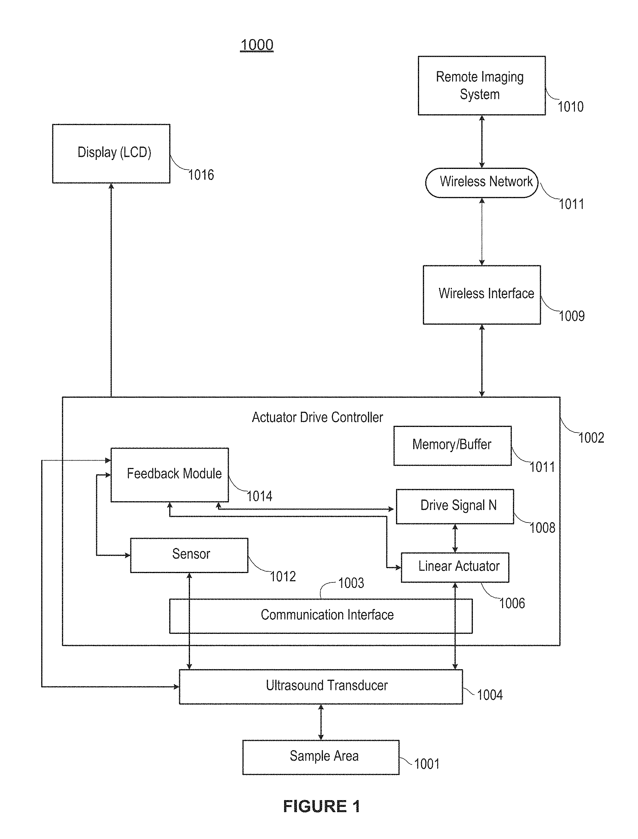
FIG. 1 is a system diagram of an example Doppler imaging system in accordance with an example.
FIG. 2 is flow diagram of an example volume flow (VF) Doppler flow monitoring approach in accordance with the example of a FIG. 1.
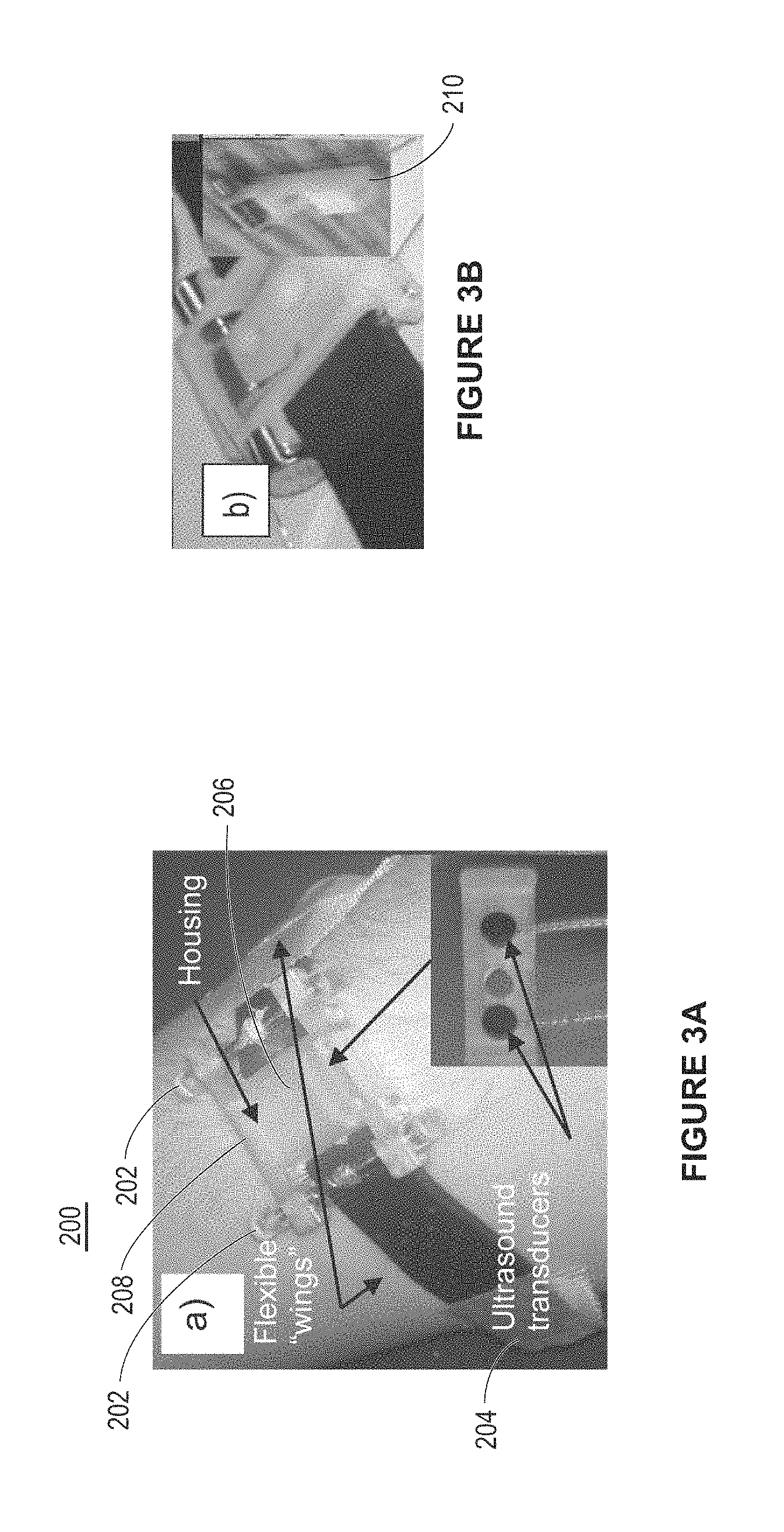
FIG. 3A is a depiction of ultrasound scanning device, with a magnetically driven linear motor, as may be used in a wrist (or limb) mountable configuration, in accordance with an example.
FIG. 3B is a depiction of a magnetic coil assembly as may be used in the device of FIG. 3A.
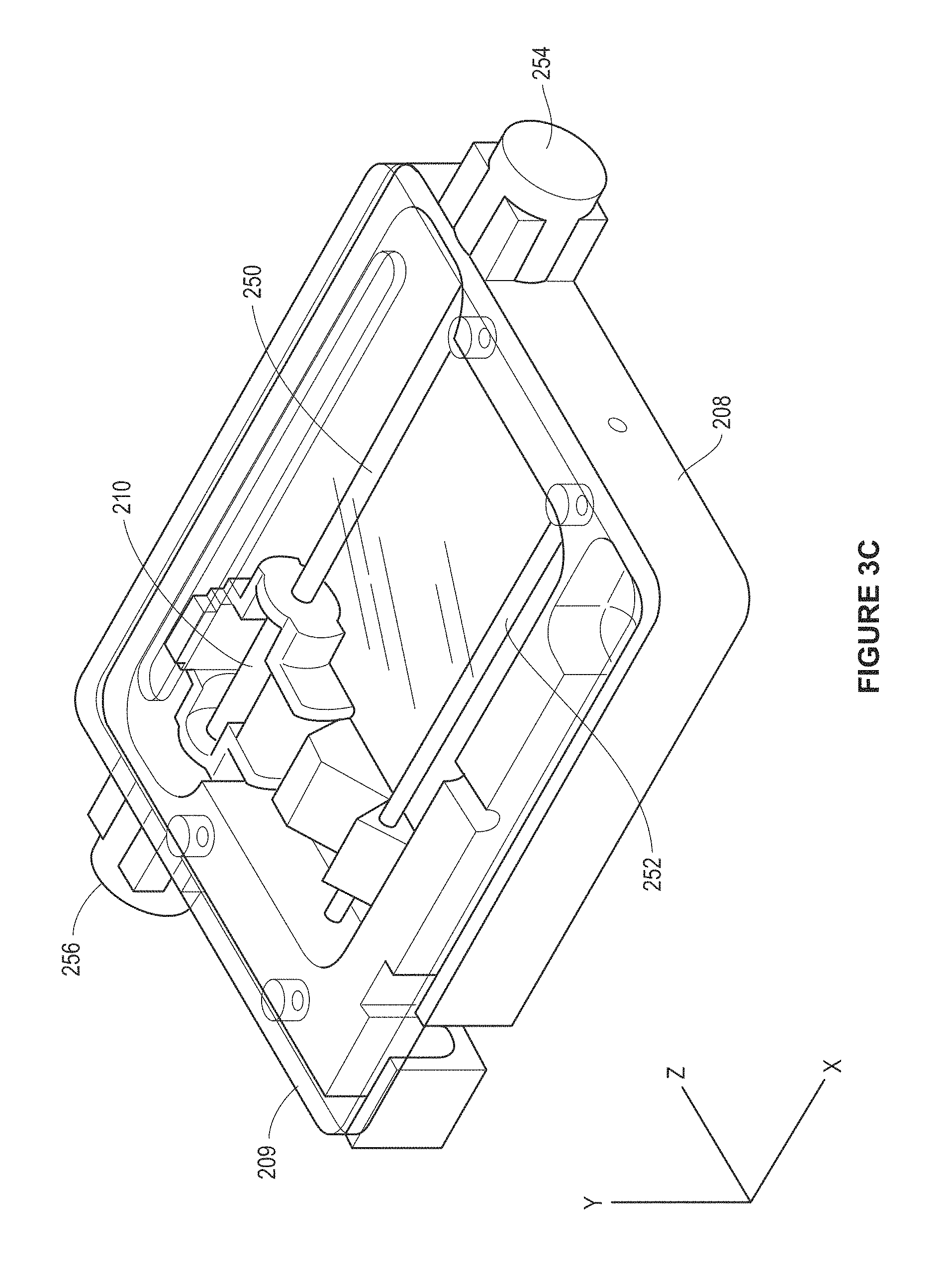
FIG. 3C is a perspective view of the device of FIG. 3A.
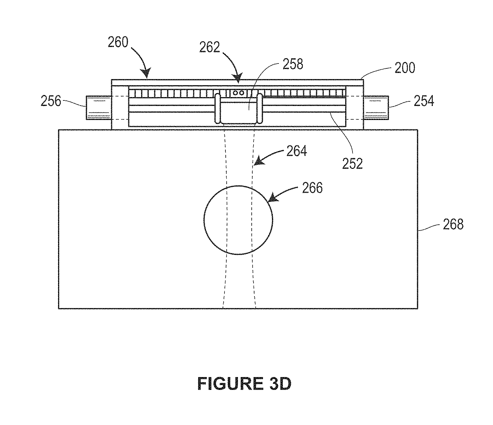
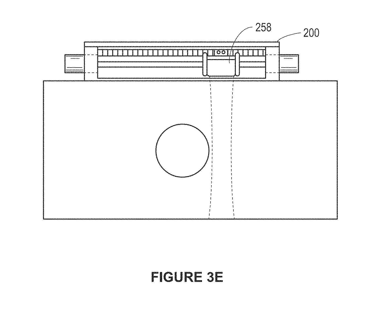
FIGS. 3D and 3E are side views of the device of FIG. 3A in first and second scan positions.
FIG. 4 is a plot of divergence of errors between a VF Doppler method and a duplex mode analysis.
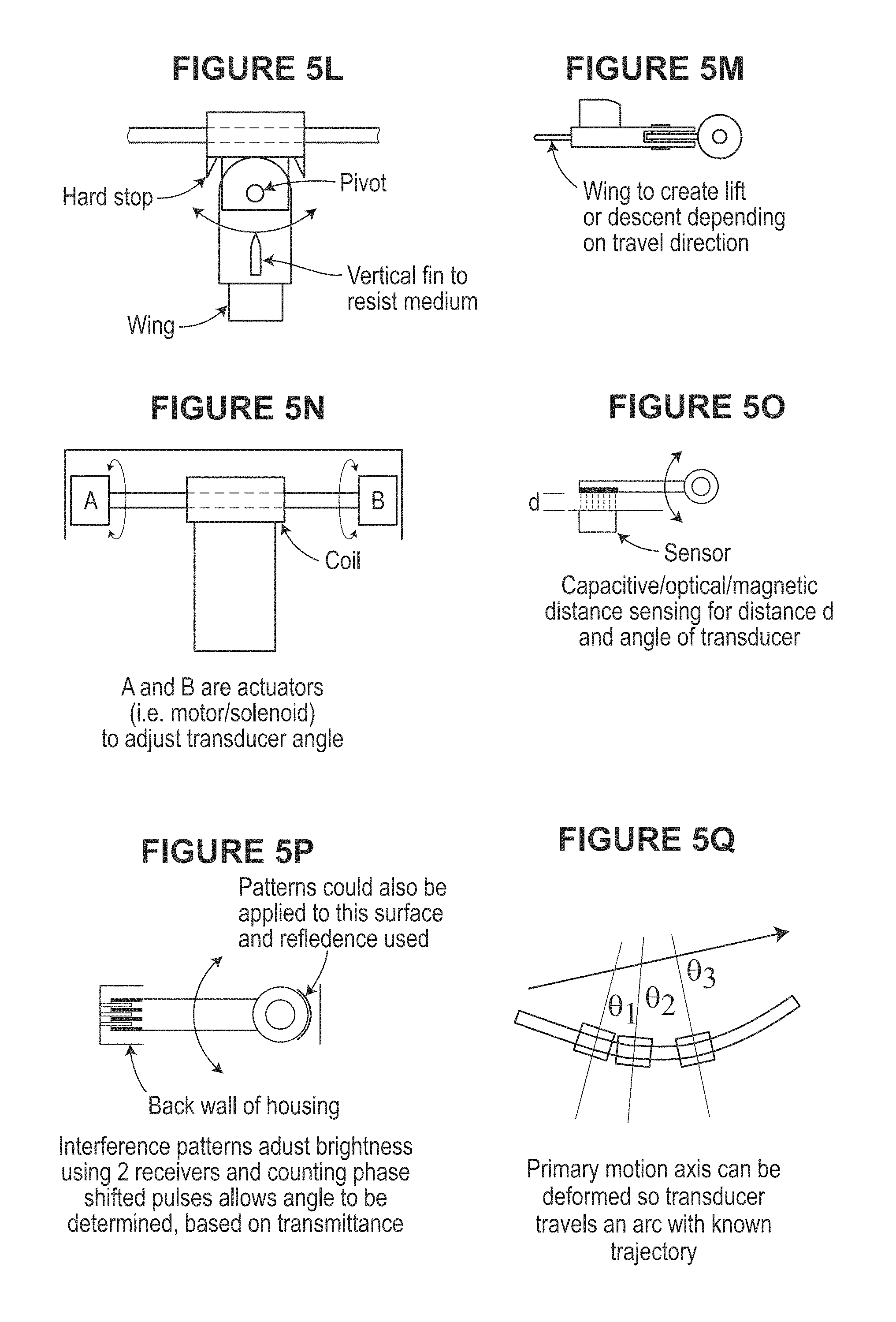
FIGS. 5A-5Q illustrate various aspects of example magnetic drive assemblies as may be used in scanning devices, in accordance with various examples.
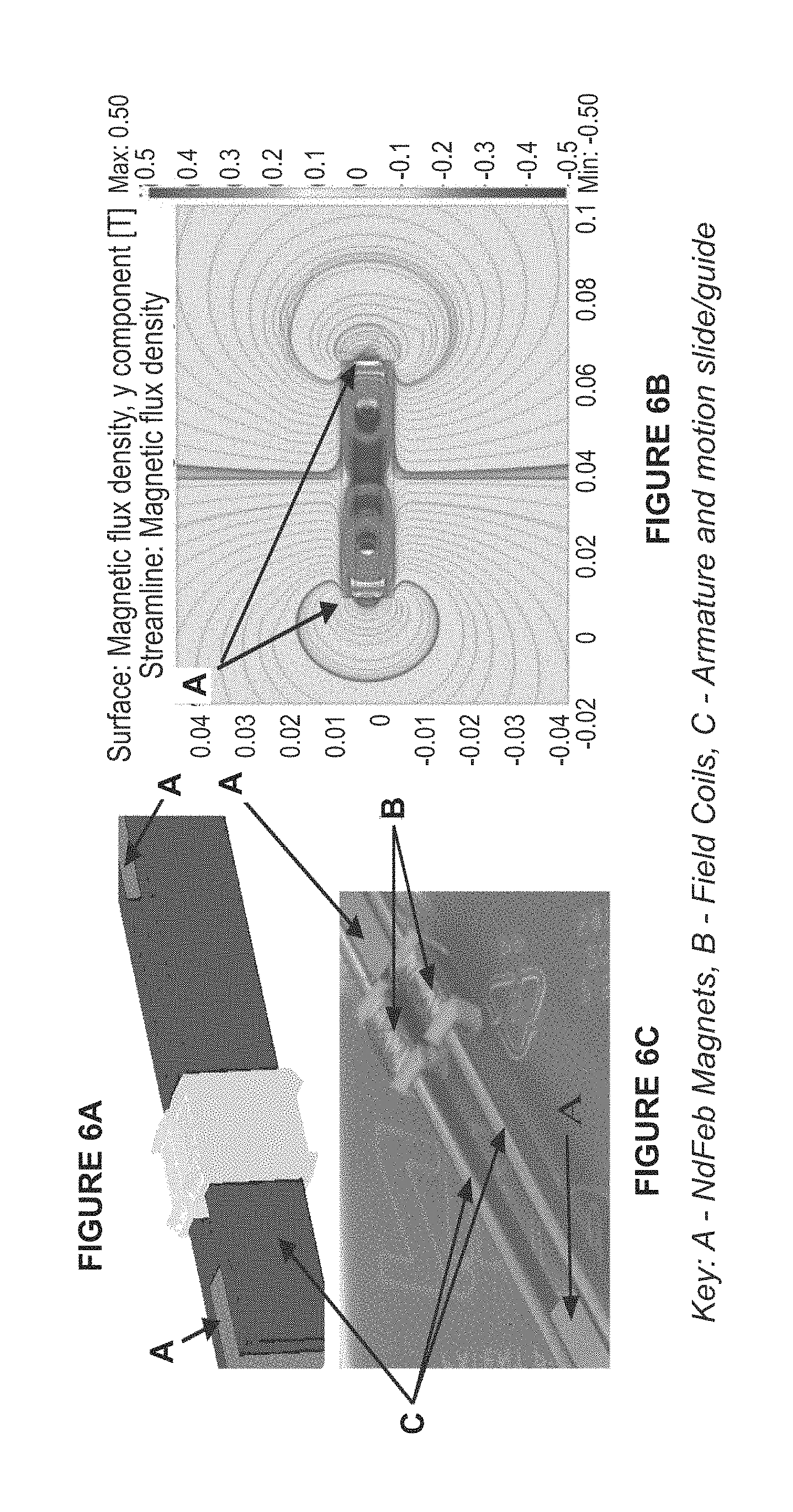
FIGS. 6A and 6C are perspective views of a dual-field coil design for a magnetic actuator. FIG. 6B illustrates a magnetic circuit simulation for the configurations of FIGS. 6A and 6C.
FIG. 7A is a plot of position versus velocity for an example movement of a linear motor.
FIG. 7B is a block diagram of a control system of scanning device to compensate for transducer motion in a dialysis configuration.
FIG. 8 is a block diagram of a scanning device in accordance with another example.
FIG. 9A is a plot of sample period versus amplitude for a scan using a single pulse drive, in accordance with an example.
FIG. 9B is a spectrogram plot that results from the operation in FIG. 9A.
FIG. 10A is a plot of scan position versus velocity; and FIG. 10B is an image of the corresponding pulse width Doppler image (or B mode image data), in accordance with an example.
FIGS. 11A and 11B are flow diagrams of an operation of an ultrasound imaging system, in accordance with an example.
FIG. 12 is a system diagram of another example scanning device.
FIG. 13A is an image of a conventional B-scan image of the cross-section of a brachial artery.
FIG. 13B is an image of the map of the correlation function with increasing correlation in higher intensity as a result of using the PW Doppler imaging analysis techniques, in accordance with an example herein.
FIG. 13C is a plot showing the correlation function for a pair of frames along the centerline in FIG. 13B, demonstrating the high decorrelation gradient at the vessel edge, in accordance with an example.
FIG. 14 is a plot showing spatial resolution for motion tracking.
FIG. 15 is a plot of transducer displacement versus RF beam correlation.
FIG. 16 is a depiction of a data acquisition technique using stacked images at different scan positions, in accordance with an example.
FIG. 17 is a system diagram of an ultrasound imaging system having a handheld ultrasound scanner device and a remote image processing system, in accordance with an example.
FIG. 18 is block diagram of example software modules that may be executed by the system of FIG. 17.
FIG. 19 is an illustration of flow dynamics during movement of a transducer assembly, in accordance with an example.
FIG. 20 is an illustration of flow dynamics during movement of a transducer assembly, in accordance with an example.
FIG. 21 is a plot drag force versus gap width for a transducer assembly, in accordance with an example.
DETAILED DESCRIPTION
FIG. 1 illustrates an ultrasound Doppler imaging system 1000 in accordance with an example implementation of the present techniques. Generally, the techniques provide a first device that has a single (or perhaps few) transducer elements (i) to generate an ultrasound signal and (ii) to transmit the signal data to a second device for processing the signal, a receiver to receive the processed information, and a screen display to display processed data, where the receiver and display screen may be an integrated device including the first device, or a separate device connected thereto through a wired or wireless connection. The techniques may include, for example, a simplified mechanical drive system to collect ultrasound data from a plurality of locations or orientations, and a second device for processing the data received from the first device (i.e. for distributed signal processing) and transmitting the processed data to the first device for display (or to the receiver-display unit that is separate from the first device). For example, in order to generate a 2D or 3D image, a region of interest (measurement window defining a sample area) may be evaluated by sampling wave reflections returning to an ultrasound transducer, of a handheld device, from short bursts of acoustic pulses sent periodically as the transducer traverses across the skin surface. The reflected waves may be sampled with the transducer actuation using a closed-loop control system to build an undistorted image of the underlying tissue. The sampled data may then be streamed (or streamed continuously during acquisition) to a central image-processing server (as the second device) for rendering into the ultrasound image, after which the data may be returned to the handheld device for display. The display screen may be mounted on the transducer module to allow an operator to introduce a needle into vessel during the localization procedure while remaining low profile to avoid interfering with the needle and provide the "window" to view the needle action on the vessel below the device during needle insertion.
In the example illustrated in FIG. 1, an actuator drive controller 1002 controls scanning of sample area 1001 using an ultrasound transducer 1004 through an interface 1003. The drive controller includes a linear actuator 1006, which may be implemented as a magnetically driven linear motor assembly coupled to the ultrasound transducer to provide support and positioning and to control scanning motion. A drive signal processor 1008 (coupled to or otherwise having a memory module or buffer 1005) provides control signals to the linear actuator, which is configured to move the ultrasound transducer along a linear path, e.g., a rectilinear path (i.e., a straight line), a curvilinear path, or some combination of the two. The ultrasound transducer may be a single element transducer or a limited linear array containing 2, 4, 6, 8, 16, or more elements. To provide scanning over 2D or 3D sample area, each transducer element may be further movable in angular directions off-axis from an axis defined by the linear actuator. The controller 1002 is coupled to receive RF and demodulated RF Doppler scan data from the ultrasound transducer 1004, for pre-processing of that scan data and communication thereof to a remote imaging system 1010. In the illustrated example, those communications are achieved through a wireless communication interface 1009, such as any of the IEEE 802.11a, b, g, and n wireless communication standards coupled to a wireless network 1011. In many examples herein, the linear actuator are implemented by a linear motor drive, such as a magnetic and/or electromagnetic linear motor drive.
The actuator drive controller 1002 is also able to receive sensed kinematic data from the ultrasound transducer, e.g., data indicating a physical characteristic of the transducer or linear actuator or data indicating an electrical state of one of the two (such as current, voltage, force, etc. indicating position, velocity or acceleration). The sensed data is supplied either directly from the transducer or through a sensor module 1012 to a feedback module 1014 within the controller.
That feedback module 1014 is configured to analyze the sensed data and create adjustment signals for the drive signal processor 1008. In this way, the actuator drive controller is able to control position, velocity, acceleration and other movements of the scanning ultrasound transducer. Controlling position and movement of the transducer in this way reduces nose and image misalignment that can result from patient or operator movement during scanning. As also further disclosed in examples below, a feedback module can provide operator-independent Doppler flow velocity monitoring or Doppler volume flow monitoring of vessels using VF Doppler algorithm or other scan data (or image data) registration technique.
In the illustrated example, the scanning device of FIG. 1 is implemented with a miniature, low-power wireless communication interface that allows integration of the scanning device as an ultrasound signal generation, acquisition and pre-processing device, within the transducer module, that distributes higher level signal processing to dedicated computing platforms such as the remote imaging system as shown. This allows the computing platforms to be developed separately, accelerating development and implementation of new image processing modules at lower cost than conventional architectures. The remote imaging system is able to perform the more complex image processing and transmit back to the scanning device ultrasound image data for display on an LCD 1016, or other dedicated local or remote, wireless or tethered display device.
The scanning device and imaging system 1000 of FIG. 1 may be used in any number of medical pathology screening applications. Example pathologies that may be examined include CV disease and carotid stenosis. The scanning device allows for rapid screening of high risk patients (e.g., patients with a possible stroke or TIA) and can obviate the need for more expensive follow-up testing among moderate-to-lower risk patients, for example, if the point-of-care testing is negative (e.g., asymptomatic patients with a bruit or atherosclerosis elsewhere). In addition to the degree of carotid stenosis, the present techniques may be used to determine other pathologies that have been investigated as predictors of stroke and indicators of vascular elasticity (i.e., echogenicity, surface ulceration). For example, anatomic/structural parameters such as intima-media thickness (IMT) have also been widely used as a surrogate marker of coronary artery disease (CAD). For IMT to be optimally useful, operator-induced measurement variability due to manual 2D measurements must be overcome, e.g., through the feedback module.
In some examples, a feedback module may be extended to perform various pre-image processing analyses on the scan data, such as compression and data transformations. A separate data packet module for assembling the scan data into a frame format for uplinking to a remote imaging system may also be included in the scanning device or implemented within the feedback module. In some further examples, the feedback module may perform more complex pre-imaging processing, such as automated edge detection and measurement to improve the accuracy of operator scanning data measurements. Such image pre-processing may be implemented entirely on the scanning device, partially on the scanning device and partially on the remote imaging system, or entirely on the remote imaging system. For systems desiring to reduce the amount of processing performed by the ultrasound scanning device, such ultrasound image processing would be performed at the remote imaging system. In terms of the feedback control for the magnetic linear actuator, by using a closed-loop controller, as shown, the feedback module can automatically counteract fluctuations in scan data, over scan cycles, due to operator movement. The feedback module, for example, may provide on-the-fly automatic registration of scan data, thus greatly reducing noise in the collected data. The feedback may also be based on independent local position information from the device such as an optical encoder or accelerometer in the device, or from current or voltage feedback from the electromagnetic drive itself.
The feedback module may also be configured to apply filtering algorithms to the scan data including computationally intensive image processing algorithms such as advanced filtering algorithms to improve edge crispness, adaptive texture smoothing to enhance boundary detection, and mathematically intensive computations to identify specific anatomical structures, detect lesions, or differentiate between pathological and healthy tissue. Although, in other examples, such filtering and analysis is performed partially or wholly at the remote imaging system.
Other data and image processing techniques described herein may be implemented in whole or in part on a scanning device controller, for example, in either the feedback module (like module 1014) or the drive module (like module 1008). In some examples, application specific data and image processing may be performed on the scanned data by the controller, such as determining total plaque area (TPA) and total plaque volume (TPV), which are used as accurate and robust markers of stroke prediction. By contrast, measurement variability of conventional 2D ultrasound imaging of plaque is due in part to manual registration, localization and integration of the series of 2D imaging planes. Therefore, accurate, 3D ultrasound imaging techniques as described herein can provide direct plaque visualization and TPV measurement important for the point-of-care assessment of asymptomatic patients, for serial monitoring, and for performing large-scale clinical trials.
An example implementation of the scanning device of FIG. 1, and discussed in further detail below, is as part of a volume flow (VF) Doppler analyzer. The VF Doppler technique is described in U.S. Pat. Nos. 6,167,765, 6,575,927, and 6,709,414, each of which are herein incorporated by reference, in their respective entirety. The technique allows the volume flow to be determined from low-cost Doppler velocity measurements with various pump flow rates, while at the same time reducing some of the major sources of error for typical ultrasound flow measurements. The flow velocity measurement can be acquired with a continuous-wave (CW) or pulse-wave (PW) Doppler, without disrupting treatment. FIG. 2 illustrates a flow diagram of the VF Doppler flow monitoring approach.
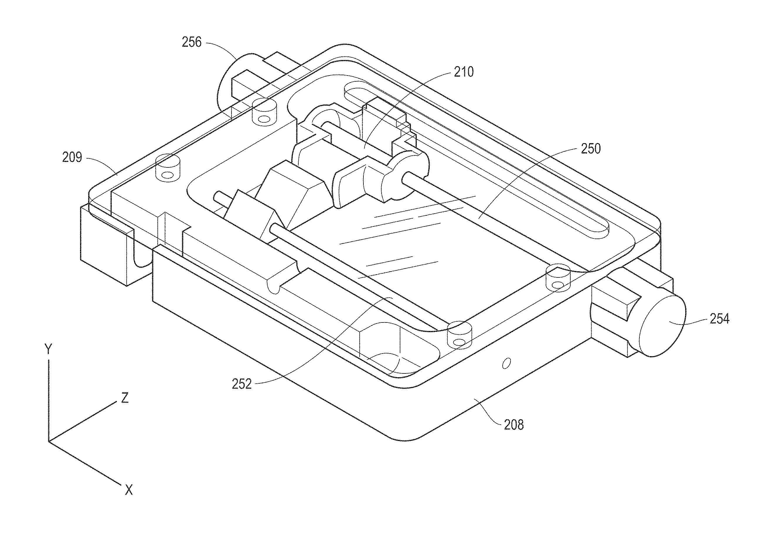
FIG. 3A illustrates an example implementation of the scanning device of FIG. 1, as may be used in a VF Doppler system. A band-aid type flexible transducer scanning device 200 includes mechanical fine adjustment knobs 202 attached to human arm. One or more CW Doppler transducers 204, in a single row array if multiple transducer elements are used, are positioned on a movable frame 206 located inside the housing 208 of the magnetic linear actuator 200. Or more magnetic coil assemblies are provided on the housing to move the ultrasound transducer assembly in response to received magnetic control signals. FIG. 3B illustrates an example implementation of magnetic coil assembly 210 (with winding coils not shown nor a PZT or other actuator which would be mounted to the assembly 210) of the linear actuator. The ultrasound transducer would be mounted on the coil assembly 210 with transducers adjacent a tissue surface side of the housing 208. FIG. 3C shows an example of the housing 208 in a more detailed view, showing guide rails 250 and 252 for linear movement of the coil assembly 210 and drive magnets 254 and 256. While two guide rails are shown, single, dual, or a multitude of rails could be used. The scanning device 200 would be placed over the area to be scanned and may be held in place on a permanent basis, for example, using a strap, or held in place for a small number of scans. An optical encoder may 262 (see, FIG. 3D) may be mounted to the assembly 210 and in conjunction with an encoder strip 260 (see, FIG. 3D) on the undersurface of a capping plate 209 determine position of the transducer mounted to assembly 210.
FIG. 3D illustrates a side view of operation of the scanning device 200. Transducers 204 are maintained in a transducer scan head housing 258 mounted on the coil assembly 210 (not shown) and movable in slidable direction on the rails 250 and 252 (only one of which is visible in this side view). The transducer scan head 258 includes a focusing mechanism to focus the ultrasound beam 264 into the sample region 268. The focusing mechanism may be fixed or adjustable, and mechanically adjustable or electronically. The focal point of the beam 264 coincides with a blood vessel 266, in the illustrated example. An encoder strip 260 registers a scan position of the scan head 258 via an optical encoder 262. FIG. 3E illustrates the scan head 258 is second scan position have scanned the entire blood vessel 266. Because the force provided by the linear actuator is proportional to the current flowing through the field coil and at low velocities the back EMF generated can be assumed to be negligible, and the DC resistance of the coil is constant. Therefore, the voltage applied to the field coil can be varied to control the current. Pulse wave modulation (PWM) can be used to drive the linear actuator; although a continuous differential voltage could also be used. The PWMs process includes adjusting the duty cycle of a square wave operating at a frequency higher than the mechanical system can respond. The mechanical system sees the average voltage applied, which corresponds to the duty cycle. If an H-Bridge circuit is used the direction of current through the field coils can be reversed. Using PWM with an H-Bridge provides a method for a micro-controller to digitally adjust the direction and magnitude of force delivered by a linear actuator. A spring may be included to provide a reaction force against which the linear actuator can press. Because the force exerted by a spring is proportional to its compression, and the force exerted by the field coil is linearly related to the current, one can obtain a controlled displacement or velocity by adjusting the current (duty cycle), which may also be adjusted for non-linear effects. The magnetic drive assembly controller implemented as a VF Doppler controller is shown as well and resides within a translucent plastic housing having a display for displaying Doppler data after pre-processing.
The scanning devices of FIGS. 1 and 3A-3E are able to improve the known VF Doppler technique in a number of fundamental ways.
First, operator-dependence and signal loss due to device motion is reduced. By using transducers having a fixed beam pattern, the VF Doppler device must be aligned precisely over the vascular access to avoid measurement error. If the device moves during the several-hour dialysis treatment, Doppler signal quality could be reduced or lost, requiring medical personnel to reposition the device. By using a feedback configuration with magnetic drive control, and track and hold analyses, such operator- or patient-induced error can be compensated for or eliminated entirely.
Second, errors at high flow rates are reduced. The VF Doppler method is robust for flow rates <1000 mL/min, the most critical range for predicting access failure. However, in the >1000 mL/min range, which is also clinically relevant, the error inherent to the VF algorithm can rise non-linearly. To be of highest clinical value overall for access monitoring, the measurement accuracy of the device should be improved in this higher flow regime. With adaptive signal feedback and the capability to shift into "duplex mode" (i.e., vessel cross-sectional area measurement multiplied by the blood velocity to give volume flow) or a mode similar to a "duplex mode," the magnetic drive assembly is able to reduce this error. The measurement error for this mode is independent of flow rate, which means that even with an error in angle and area, accuracy may surpass the VF Doppler method as flow rates exceed 1000 mL/min. FIG. 4 illustrates an example divergence of errors between VF Doppler method alone and the duplex mode analysis.
Third, the data collected by the VF Doppler method can be used on applications beyond end stage renal disease (ESRD), of the dialysis setup of FIG. 2. Because pump-controlled flow is necessary for determining flow with VF Doppler, generally speaking, the VF Doppler method cannot be easily applied elsewhere. However, there is great demand for blood volume flow measurement for many clinical areas, including Peripheral Arterial Disease (PAD). By having motion control capabilities of the magnetic drive and feedback system produce accurate vessel size estimation and angle correction, volume flow monitoring will be possible in applications with no dialysis blood pump.
Fourth, the low-cost nature of the VF Doppler smart sensor device with the above features creates the potential to improve dialysis vascular access care, given that accurate flow monitoring will become an affordable part of every dialysis treatment. The present techniques allow the integration of the scanning device into a compact VF Doppler smart sensor for operator-independent flow monitoring. Doppler flow information acquired by the device may be wirelessly uploaded to a remote imaging system using a low-power short-range wireless link. That remote imaging system performs image processing and may be connected to or part of a medical records management system, medical alert system, or an automated drug delivery system. The remote imaging system may be integrated with decision analysis algorithms and/or risk assessment algorithms to improve diagnostic decision making. These decision support systems (DSS) may be based on demographic data or may use patient history data, and may include learning algorithms based on any number of inputs. Using these algorithms the decision support may "learn" and improve risk assessment or improve the information given to the clinical to improve diagnostic decision making. These decision support learning algorithms may be based on data collected across patient groups, historical data collected for each particular patient, or some combination thereof. Beyond the ESRD setting, there is great potential for use in Peripheral Arterial Disease (PAD), a common disease affecting 12 million people in the United States.
The remote imaging system may be a centralized computer system, such as a server, as shown in FIG. 17, that wirelessly communicates with numerous wireless ultrasound scanning devices (e.g., handhelds) located throughout a facility, at the patient's point of care or otherwise. The centralized computer system would communicate with the various devices through an address-specific data format that may be encrypted in some examples. The distributed approaches described herein facilitate scalability of the computational power according to the utilization (e.g., number of simultaneous scans from one device or from the many concurrently operating scanning device). Therefore, while one remote imaging system is shown, ultrasound image processing may be achieved by using numerous remote systems in a server configuration. This allows for processing of sub-sections of an image in parallel to speed up processing. Or in other examples, each of the different remote systems could have specialized processing functions, such as automated diagnosis/region of interest detection, where image data is communicated between the remote systems before sending the completed ultrasound image back to the "Doppler window" device.
FIG. 17 illustrates system 2000 having a handheld system 2002 coupled to remote system 2004, which may serve as a remote imaging system. The handheld system 2002 includes an ultrasound module 2006 a linear actuator, formed having a magnetic drive controller 2008 and a magnetically driven ultrasound probe 2010. The ultrasound module 2006 in the illustrated example includes functional blocks for performing ultrasound image processing and for interfacing with the host server 2004, for performing additional, more processing intensive image processing. An embedded application module 2012 provides high level platform providing user interface modules, display processing controls, ultrasound image storage and processing, and communications interfaces. The application module 2012 accesses library functions 2014 and low level drivers 2016 to interface with physical hardware 2018 within the handheld device 2002, controlling interfacing between that physical hardware 2018 of the ultrasound module 2006 and the actuator controller 2008, e.g., through a serial interface, and the ultrasound probe 2010, e.g., through a radio frequency (RF) interface, and through wireless (e.g., 802.11, 802.15, etc.) or wired (e.g. Universal Serial Bus) communications.
The actuator controller 2008 includes a control module 2020 that interfaces and controls a physical hardware interface 2022 in communication with the probe 2010, and more specifically, in the illustrated example, with a linear motor 2022 for the probe, a position sensor 2024, and an ultrasound transducer 2026.
The host server 2004 includes an application module 2028 for interfacing with the handheld system 2002, interfacing with a user of the server 2004, performing image processing, image data storage, etc. The application module 2028 interfaces with library functions 2030 and host hardware 2032. In the illustrated example that host hardware 2032 may include a network interface, including an ultrasound driver interface, for communicating with the handheld 2002. The host hardware 2032 may also interface with a remote data storage system 2034, such as an electronic medical records database.
FIG. 18 illustrates an example implementation of FIG. 17 at a software-level where instructions are executed to perform the various operation described herein. While FIG. 18 is described as implemented in hardware, it will be appreciated that the functions described may be implemented in software, hardware, or firmware, or some combination of these. The system 3000 includes library functions 3002 that operate as high-level executable instructions at the ultrasound module and/or at the host server, such as those illustrated in FIG. 17, where these instructions include (in additional to others described herein) analyzing spectral Doppler signals, extracting flow rate from spectral Doppler signals, rendering B-mode images; compute correlation coefficients, computing speckle motion, detection motion in a scan field, computing motion region dimensions and area, connecting to databases (SQL, MySQL, Oracle, etc.), and uploading analyses to the database. Low-level library functions 3004, as may be implemented specifically by the ultrasound module in the handheld, are also shown. The instructions include instructions such as configuration instructions for the ultrasound module, establishing remote hosting, establishing file on a local storage, opening buffer memory in RAM, acquiring n 1-D beams, acquiring n 2-D images, configuring the magnetic linear actuator, and synchronizing the linear actuator with the ultrasound transducer.
The peripheral hardware interface drivers for the ultrasound module, e.g., the physical hardware interface 2018. An ultrasound CPLD interface 3008 is able to send n pulses using the ultrasound transducer, gate the receiver control for the received ultrasound signals, and set the pulse repetition frequency. A controller interface 3010 provides positional control for the linear actuator, such as instructions to move home, move at a velocity x to scan a sample area, etc. Local storage driver 3012 is shown in an example SD Card driver and interface. A communications driver 3014 is able to connect to an access point and send and receive raw data from/to the handheld for processing. A graphics driver 3016 is also shown, for displaying any instruction menus on a LCD for user input, and to display depictions of the collected image data. A user input is also shown 3018, along with power control drivers 3020 for the handheld, which include instructions to shutdown the linear actuator, shut down the handheld device, or at least put the device in a sleep mode for battery status storage.
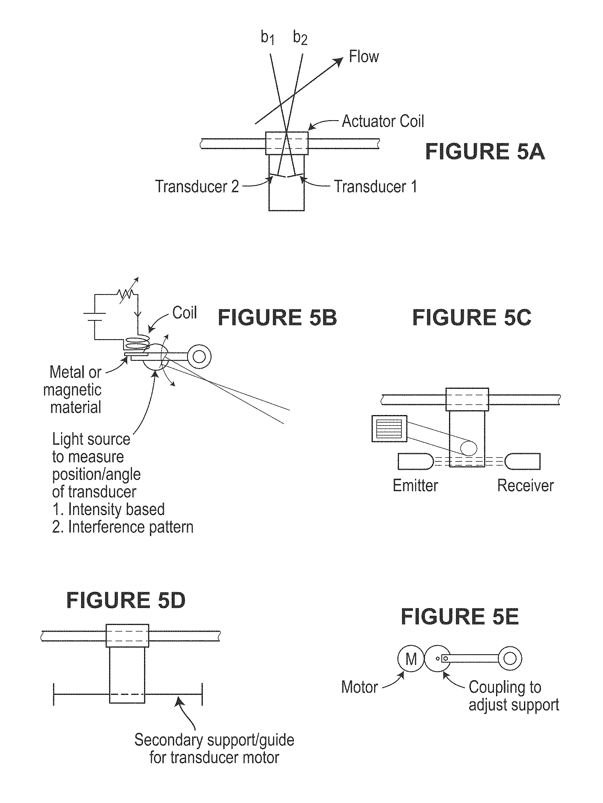
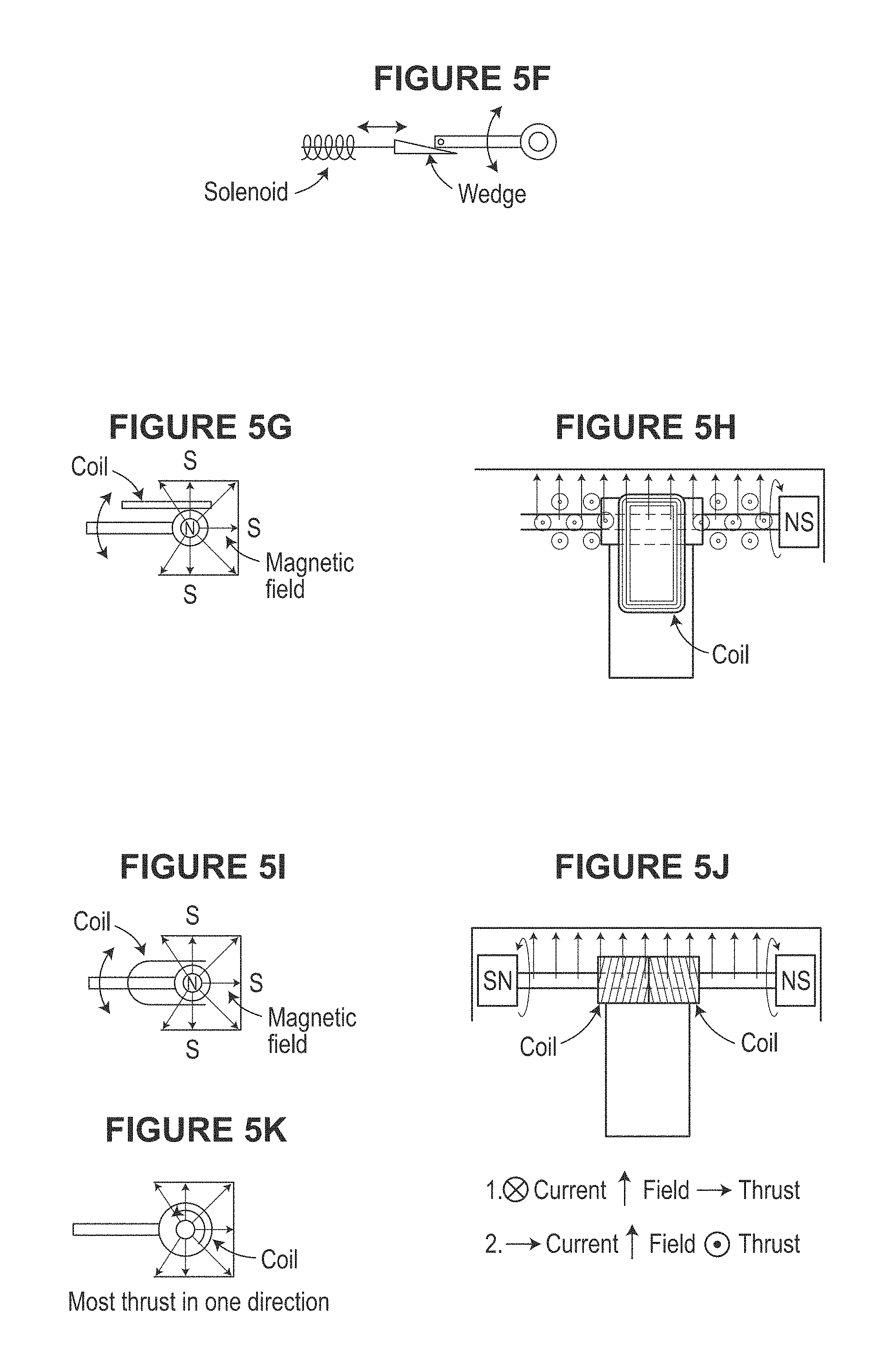
FIGS. 5A-5Q illustrate various aspects of example magnetic drive assemblies as may be used in the scanning devices described herein. While, a single rail guide linear actuator is illustrated, dual or multitude of rails or guides may be provided to guide the transducer motion along a path. Some rails or guides may be used to generate the primary actuation force, while other may be used to constrain the motion. Either the rails themselves may be electrically or mechanically manipulated or deformed, or axes not constrained by the rails may be subjected to forces to induce variations to the transducer path. For example, if a single rail with circular cross-section is used, the transducer may be free to rotate around the rail. A magnetic field may be applied in such a fashion to induce a torque to the transducer. Feedback of the angular position could be used to magnetically levitate this axis at a controlled elevation to control scanning. This could be used to control the angle of isonification for Doppler based flow measurements, or could be used to sweep the transducer in an arc, so together with the linear motion, a 3D volume could be scanned. These techniques of actuation for these additional axes could be, but do not need to be magnetic. Methods employing piezo-electric motion or motion occurring due to interaction with the other mechanical components including fluids incorporated within the device could be used.
In any event, any suitable mechanisms for obtaining additional angle change in conjunction with using magnetic drive mechanism may be used. Some examples include those illustrated. For example, the angle information may be related to the trajectory of blood flow, where knowing the trajectory of the flow, automatic angle correction of both the azimuth and elevation of the blood flow may be achieved. The angle of the flow can be determined when two discrete angles are used for the isonification beam. This allows the resolution of both the azimuth and inclination of a flow field relative to the polar coordinate system associated with the ultrasound transducer. Resolving both these angles allows accurate direct measurement of the blood flow velocity through a vessel using simple, low cost Doppler ultrasound technology. Utilizing, pulsed-wave (PW) ultrasound with the linear transducer and resolving the accurate blood flow velocities over a 2D plane, allows the direct measurement of the blood volume flow though a vessel per unit time to be determined. This may be used along with a clinically-significant metric for peripheral artery assessment.
Because the common expression for Doppler shift would assume the acoustic wave from the transducer propagates parallel to the blood flow, the expression becomes insufficient in some peripheral vascular applications, where it is difficult to align the ultrasound transducer on the surface of the patient's skin to meet the this parallel flow constraint. The vessel most likely runs approximately parallel to the surface of the skin, but do not run perfectly perpendicular to the surface of the skin. Since, no Doppler shift is detected if the transducer is perpendicular to the vessel, an ultrasonographer may apply some angle between the transducer (and acoustic wave), and the vessel under investigation, termed the Doppler angle, .theta.. Typically, this is estimated from an ultrasound B-mode image and manually entered as a correction factor into the ultrasound machine. Equation 3 provides the typically used equation to determine the expected Doppler frequency shift when the Doppler angle is known. FIGS. 5A-5S illustrate various aspects of using angle deflection during ultrasound scanning and/or ways to correlate Doppler angle to vessel position and blood flow direction. The angle deflection is able to create scanning in a second direction at an angle to that of first scanning direction defined by the axis of the guide rails.
Because the transducer may be moving in a liquid medium to facilitate acoustic coupling, fins or other measures of resistance can be integrated into the transducer design, to create a torque, rotating the transducer around a pivot when translating to the left (i.e. to the left, to downward), and rotating in the opposite direction when translating to the right. See, e.g., FIG. 5G.
Magnetic levitation for precise angular control may utilize an angular sensor and actuator. See, e.g., FIG. 5B.
Discrete mechanical actuator (i.e. solenoid) to adjust angle is shown in FIG. 5D.
Rotation of the scan head guide, using stepper or servomotor is shown in FIG. 5C.
An additional winding on the primary actuator to induce a torque on the transducer head is shown in FIG. 5E.
Implement dual windings on the primary actuator coil 90.degree. (or as appropriate) relative to each other, each at 45.degree. (or as appropriate) to the primary thrust direction. Should a balanced actuation current be applied to both coils, thrust parallel to the primary direction of motion will result. If there is an imbalance in the current supplied to each winding, a torque will be developed, allowing rotation around the primary motion axis. See, e.g., FIG. 5F.
Adjustment of the primary motion axis to rotate transducer is shown in FIG. 5H.
Utilized deformation of the primary motion axis to control trajectory along an arc is shown in FIG. 5L.
Integrating two statically offset transducers in the ultrasound scan head with known angle difference between them is shown in FIG. 5A
Capacitive, inductive, or optical distance measurement between transducer and transducer housing (see, e.g. FIGS. 5I and 5K) applies to angle actuation concepts of FIGS. 5B, 5C, 5D, 5E, 5F, and 5H.
Optical interference patterns (see, e.g., FIG. 5J) applies to angle actuation concepts in FIGS. 5B, 5C, 5D, 5E, and 5F.
Linear optical encoders, or accelerometers can be used to measure position along a rail of known geometry as is shown in FIG. 5L.
In other examples, a linear 1D or 2D ultrasound array may be used instead of a single transducer element and both mechanical and electrical beam forming used to acquire the ultrasound data. The ability to adjust the transducer angle as a function of position or time provides the opportunity to implement synthetic aperture techniques in order to improve the resolution of the resulting ultrasound image.
The magnetic drive is a linear actuator in the present examples, although any number of alternative actuators may be used. A wire-element carries a current and responds to magnetic fields for actuation. The force on a wire-element of length carrying a current of magnitude in a static magnetic flux density is given by fundamental equations including Maxwell's Ampere Law, Faraday's Law, and the electric Form of Gauss' Law and Magnetic Form of Gauss' Law provided in the following well known forms:
.times..times..times..gradient..times..differential..differential. ##EQU00001## .gradient.D=.rho., .gradient.{right arrow over (B)}=0, where, {right arrow over (E)} is electric field intensity, {right arrow over (D)} is electric flux density, {right arrow over (H)} is magnetic field intensity, {right arrow over (B)} is magnetic flux density, {right arrow over (J)} is current density, .rho. is electric charge density. We maximize force F by design of the magnetic circuit in conjunction with armature design to ensure frictional losses are overcome. FIGS. 6A and 6C illustrate a dual-field coil design with a travel of about 2'' developed for the actuator. The magnetic circuit selected after analysis contained two Neodymium Iron Boron (NdFeB) magnets with a rectangular cross-sectional thickness of 0.21'' (red) attracting two steel bars (blue) 1/8.sup.th'' thick forming the armature and motion slide/guide, as shown in FIG. 6C. The coils of the armature are wound onto 2 plastic formers; the actuators that support the ultrasound transducer. In FIG. 6B, note that comparatively strong magnetic flux density resides within the confines of the steel bars and falls rapidly external to this region. This is desirable to reduce the effects of high magnetic fields outside the device. Importantly, the direction of the magnetic flux density is nearly orthogonal to the armature coil direction maximizing the force generated, {right arrow over (idl)}.times.{right arrow over (B)}. FIG. 6A illustrates a CAD model of components; FIG. 6B illustrates a COMSOL magnetic circuit simulation; and FIG. 6C illustrates a prototype immersed in mineral oil (ultrasound coupling medium) used for evaluating design.
FIG. 7A shows a typical flow profile obtained during a laboratory experiment on the flow phantom. The x-axis represents the flow measurements. A 2.sup.nd order regression function has been fitted to the data to illustrate the flow profile as the ultrasound transducer is manually moved across the access. Typically, in clinical settings, this motion would be classified as a measurement error due to patient movement, positioning error or other factors. It can be seen that the maximum flow rate measured in this experiment was about 65 cm/s. If less than 10% measurement error is required due to transducer misalignment or patient motion artifacts, a positioning error of less than 1 mm is required and our design will meet 0.1 mm position control or better. The scanning device may be programmed to track across the access, scan and record so the linear actuator can return to the optimal location. Using the same scanning technique, estimates can be made about the vessel diameter.
FIG. 7B illustrates an example control system 600 that may be implemented on the scanning device to compensate for transducer motion to enable blood volume flow measurements to be obtained in a dialysis configuration. Because the force provided by the linear actuator is proportional to the current flowing through the field coil and at low velocities the back EMF generated can be assumed to be negligible, and the DC resistance of the coil is constant, the voltage applied to the field coil can be varied to control the current. One way to achieve this is by using PWM, which includes adjusting the duty cycle of a square wave operating at a frequency higher than the mechanical system can respond. In this way, the operation may be similar to that described in reference to FIG. 3B.
Should stick-slip become an issue; the controller may be configured to vibrate the actuator at periodic times or in response to a sensed physical condition or electrical condition, to keep the system in the kinetic friction region. An alternate solution to static friction would be to implement a pull-out boost current phase when the linear actuator begins moving. Either of these methods may be used in a singular open-loop configuration. While in other examples, the closed-loop position control formed by the feedback module may be used, such as by using back-EMF velocity measurement (integrated to get position) or optical position measurement. For the back-EMF method, the voltage generated by the field coil during the off-phase of each PWM cycle may be measured by the feedback module are sent to the feedback module, where the magnitude is proportional to the velocity of the coil. The optical position measurement approach may use a series of high-resolution (0.1 mm) transmissive or reflective marking inside the housing, which can be counted as the field coil moves along the armature.
FIG. 8 illustrates a scanning device 700 in accordance with another example implementation. The scanning device may be powered by a 3.6V Lithium Polymer rechargeable battery. A low-power microcontroller (LP-MCU) controls the ultrasound transducer (single element or few elements in a one dimensional array) pulsing and acoustic signal acquisition by a low-power analog to digital converter (LP-ADC) over a simple low-speed serial interface (LS-SIO) running at 32 MHz. Along with the power supply (PSU) and boost converter, the power amplifier (PA) provides the current and impedance matching circuitry for correct pulsing. A transducer frequency of between 5-10 MHz has been chosen to allow appropriate imaging depth, since the acoustic wave attenuates at around 0.5 dB/MHz/cm for soft tissue. The high-voltage (HV) protection, transmit-receive switch prevents saturating or damaging the time-gain low-noise amplifier (LNA). The receive signal conditioning circuitry is divided into a special block preparing the RF signal for direct sampling for B-scan imaging, and a parallel block for bi-directional PW Doppler using hardware based baseband I/Q demodulation.
For implementations such as PW Doppler constructing 2D images of the bi-directional blood flow, the sampling rate will be substantially below the high-speeds of standard ultrasound machines. This means that Baseband Quadrature Demodulation may be performed in the analog domain with the local oscillator tuned to the transmit frequency. After digitization, the signal is processed through a standard Fast Fourier Transform (FFT).
The scanning device may be designed with any standard depth of interest, were 4 cm is a preferred depth that may be achieved using the acoustic wave in tissue of 1500 m/s, allowing the pulse duration in the tissue to be around 53 micro-seconds. The acoustic wave velocity in tissue limits the pulse-to-pulse sampling rate of the system to around 18 kHz. At 2 MSPS, each pulse will be sampled 106 times, once every 500 ns (1.5 mm resolution). For a three-fold increase in resolution (0.5 mm), two additional ADCs can be used with staggered sample delay. If a 64-point FFT is generated, 64 pulses at the same location are taken, requiring a total of about 3.4 ms to complete. For a 3 cm wide area to be investigated at a resolution of 0.5 mm, 60 lateral scan-lines yield 0.2 s per image, resulting in a 5 Hz frame.
FIGS. 9A and 9B illustrate the results of a MATLAB simulation constructed to test the sampling method for obtaining the flow information for a single scan line. A parabolic flow profile 1.5 cm wide with a peak frequency shift of 5 kHz was constructed approximately 3 cm below the surface. Depth dependent attenuation was considered to be compensated for by the time gain amplifier. FIG. 9A provides a snapshot of the sampling over 7 micro-seconds for a single pulse using a 2 MSPS ADC (0.5 us sampling period). Over the sampling period the acoustic wave will propagate 0.08 mm. This pulse-sample procedure is repeated 64 times at a rate of 25 kHz in order to gather sufficient information to generate an FFT at each discrete depth as well as obey the Nyquist criterion. FIG. 9B provides the resulting spectrogram, where each vertical slice comprises a single 64-point FFT.
The scanning device in FIG. 8 is a dual mode device, having a PW Doppler scanning stage and a B Scan scanning stage. The B-scan imaging may be performed in parallel with the PW Doppler imaging operating at 8 MHz. Sampling at greater than twice this frequency is required according to the Nyquist criterion. Practically, however, approximately 10 data points per wave period are used, resulting in standard sampling of the reflected waves at around 80 MSPS. This customarily requires a high-speed ADC, special digital interfaces, and a sufficiently powerful processor with adequate storage to handle the data bandwidth and associated signal processing. All these architectural factors significantly increase the complexity, power budget, size and cost of these systems. The present techniques, by contrast, use a lower speed (2 MSPS) ADC and a high performance track and hold front-end. Sequential acoustic pulses will be transmitted, shifting the point at which sampling begins in order to fulfill Nyquist sampling criterion. Table 1 shows example frame rates that may be achieved.
TABLE-US-00001 TABLE 1 Estimated frame rate trade-off between lateral and axial resolution, and scan depth. Lateral Axial resolution resolution Scan Depth (cm) (mm) (mm) 2.00 4.00 6.00 8.00 0.25 0.5 10 Hz 5 Hz 3 Hz 3 Hz 0.5 0.5 21 Hz 10 Hz 7 Hz 5 Hz 0.75 0.5 31 Hz 16 Hz 10 Hz 8 Hz 0.25 1 21 Hz 10 Hz 7 Hz 5 Hz 0.5 1 42 Hz 21 Hz 14 Hz 10 Hz 0.75 1 63 Hz 31 Hz 21 Hz 16 Hz 0.25 1.5 31 Hz 16 Hz 10 Hz 8 Hz
Used in a "Doppler Window" application, in which the scanning device communicates the scan data to a remote imaging system for formation of the ultrasound image, the acquired data from the scanning device will be streamed over a wireless link (scan-line and/or 8-bit decimated Doppler I/Q channels=2 MSPS.times.2 bytes=32 Mbps uncompressed with no headers) to a signal processing server, e.g., the remote imaging system, where the FFT and associated processing may be performed and where the rendered image is returned back to the display on the hand scanning device for display, minimizing the complexity of the imaging hardware. FIGS. 10A and 10B provide an example of image processing that will be performed, in order to display the vessel for cannulation. The data in FIG. 10A, similar to that of FIG. 7A above was obtained by positioning a transducer at 1 mm positions across a flow phantom in our laboratory. FIG. 10B illustrates the mapped PW Doppler image data or B mode image data that results or B mode data interlaced or otherwise combined with color flow Doppler measurements.
FIGS. 11A and 11B illustrate a diagram 800 for an ultrasound imaging system implemented in a "Doppler window" configuration. Initially, at a block 802, the actuator drive controller determines drive scan signals, e.g., for CW or PW Doppler scanning, and provides those to ultrasound transducer and the linear actuator. These drive scan signals will control linear actuation of the transducers along a path defined by the linear actuator. These drive signals may further include controls for scanning transducer elements along angular scan paths, during translation alon
D00000
D00001
D00002
D00003
D00004
D00005
D00006
D00007
D00008
D00009
D00010
D00011
D00012
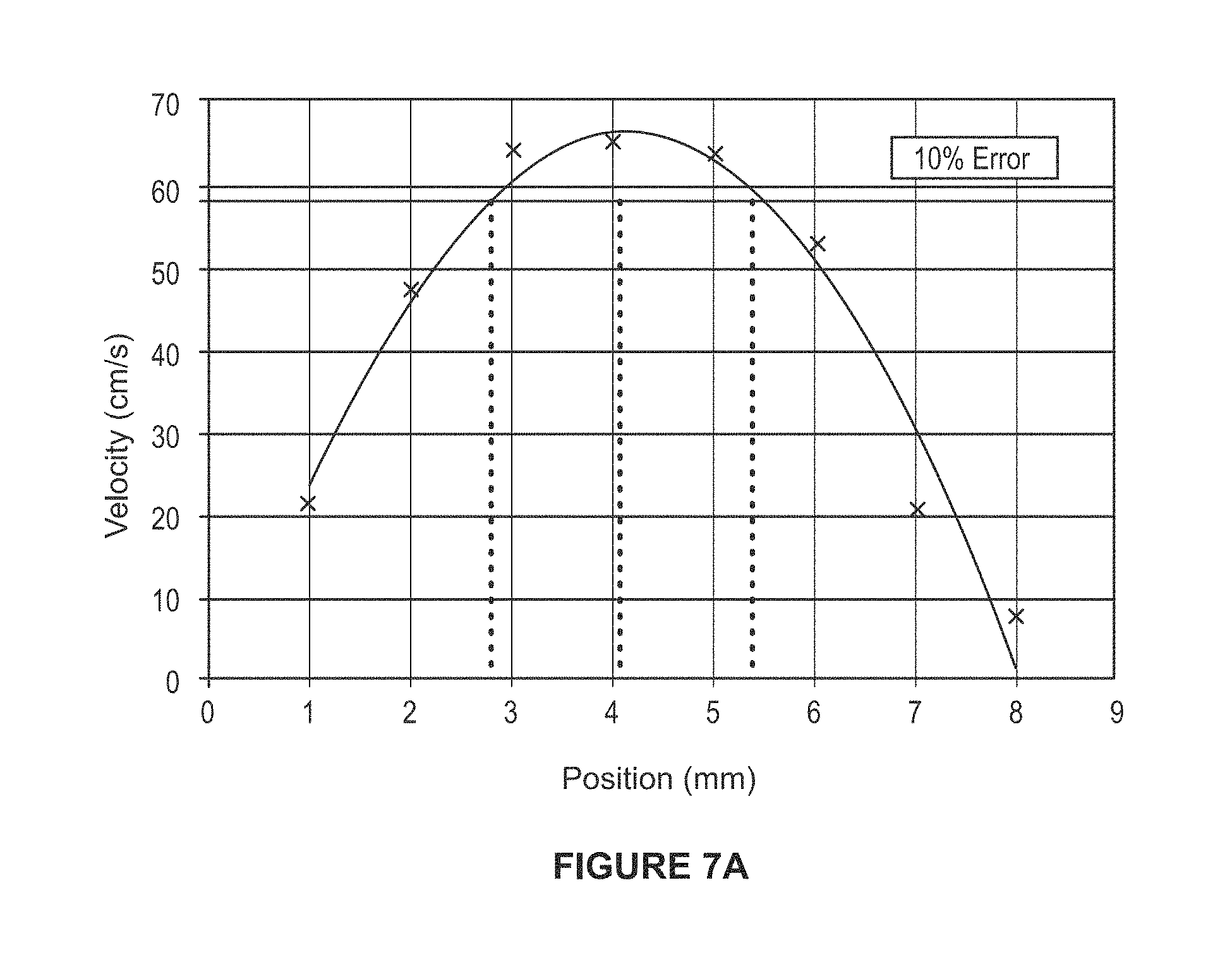
D00013
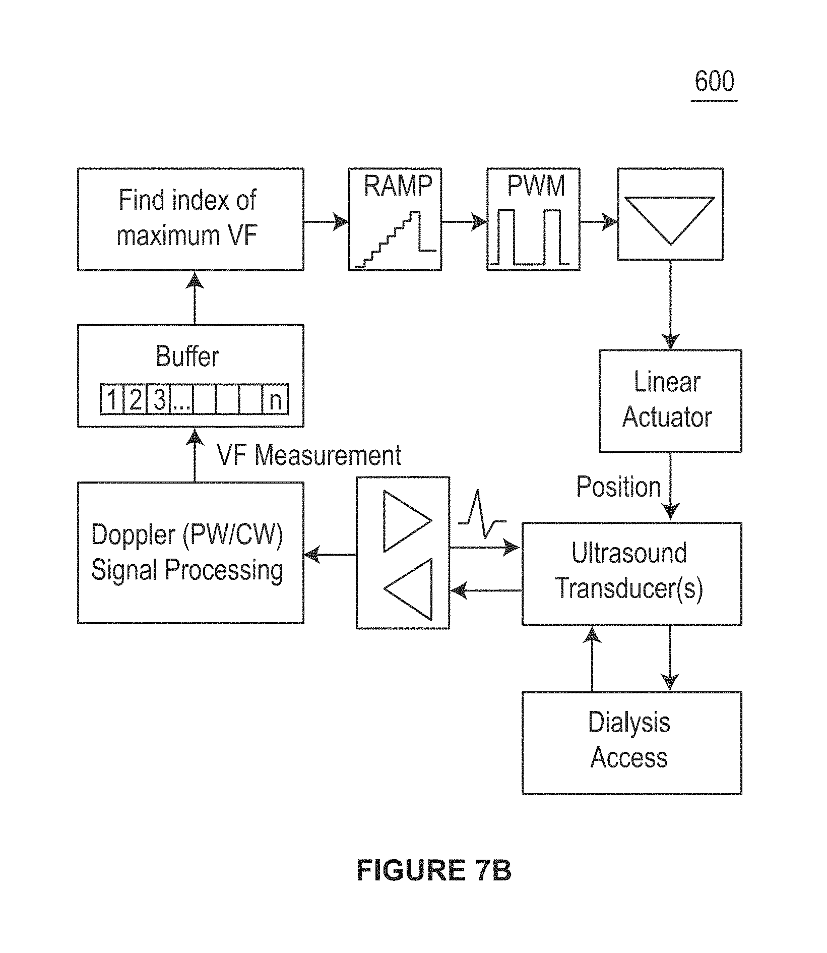
D00014

D00015
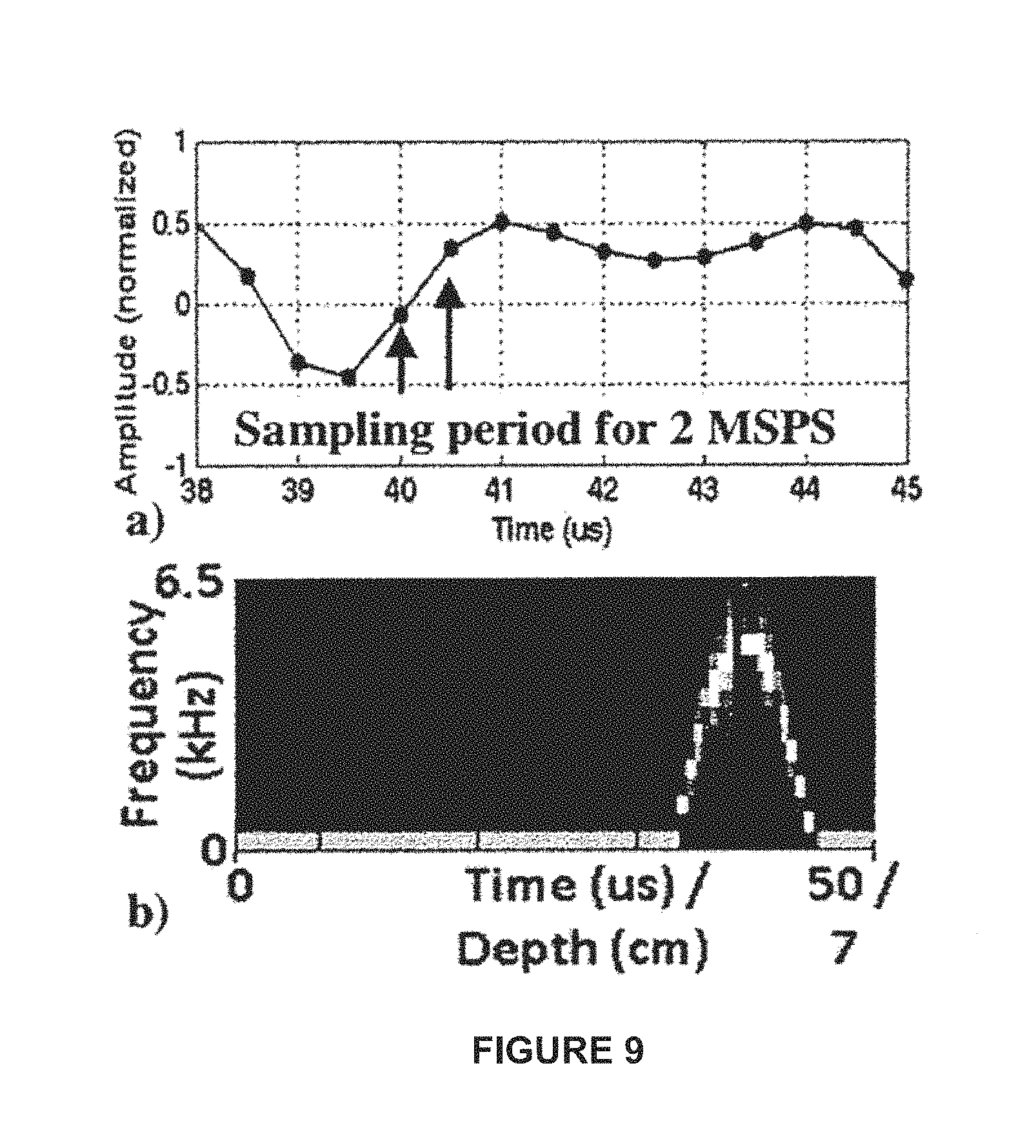
D00016
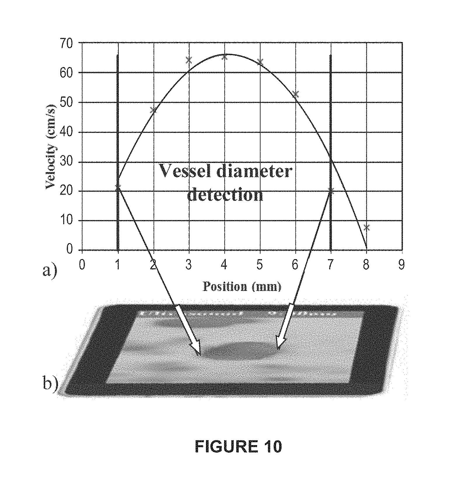
D00017
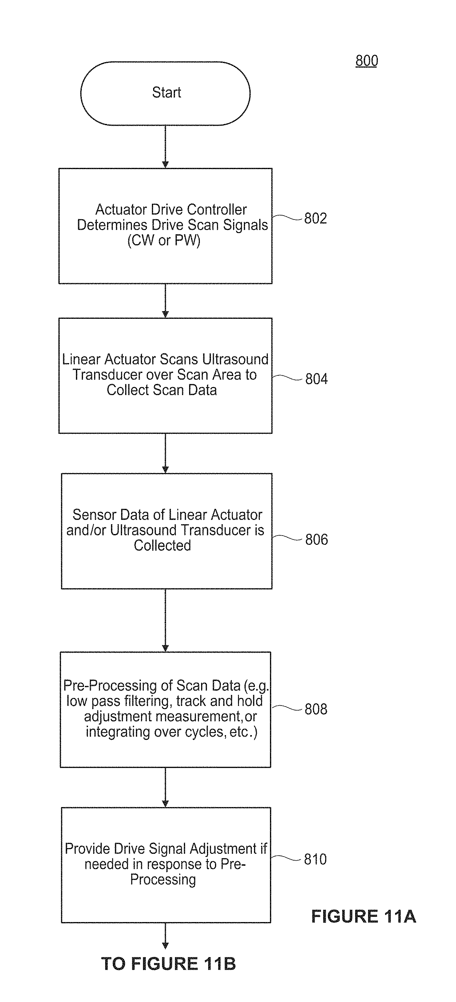
D00018
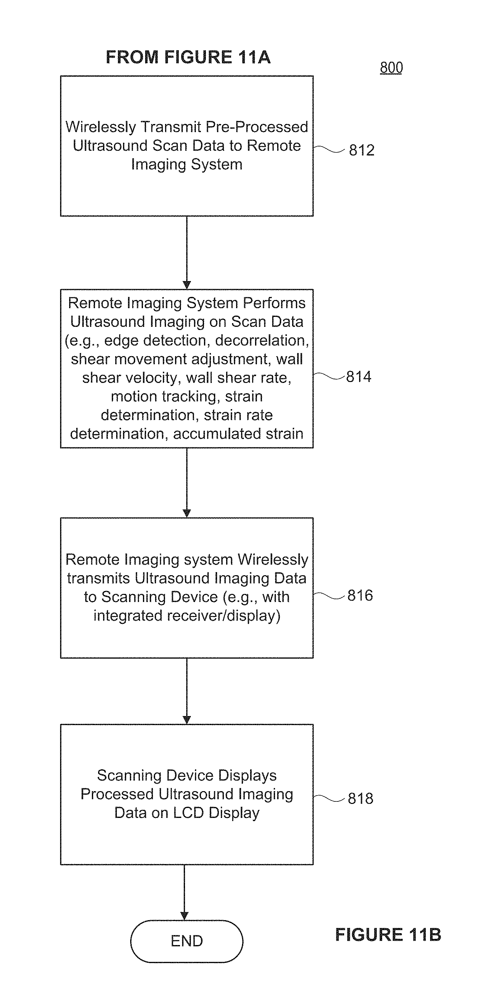
D00019

D00020
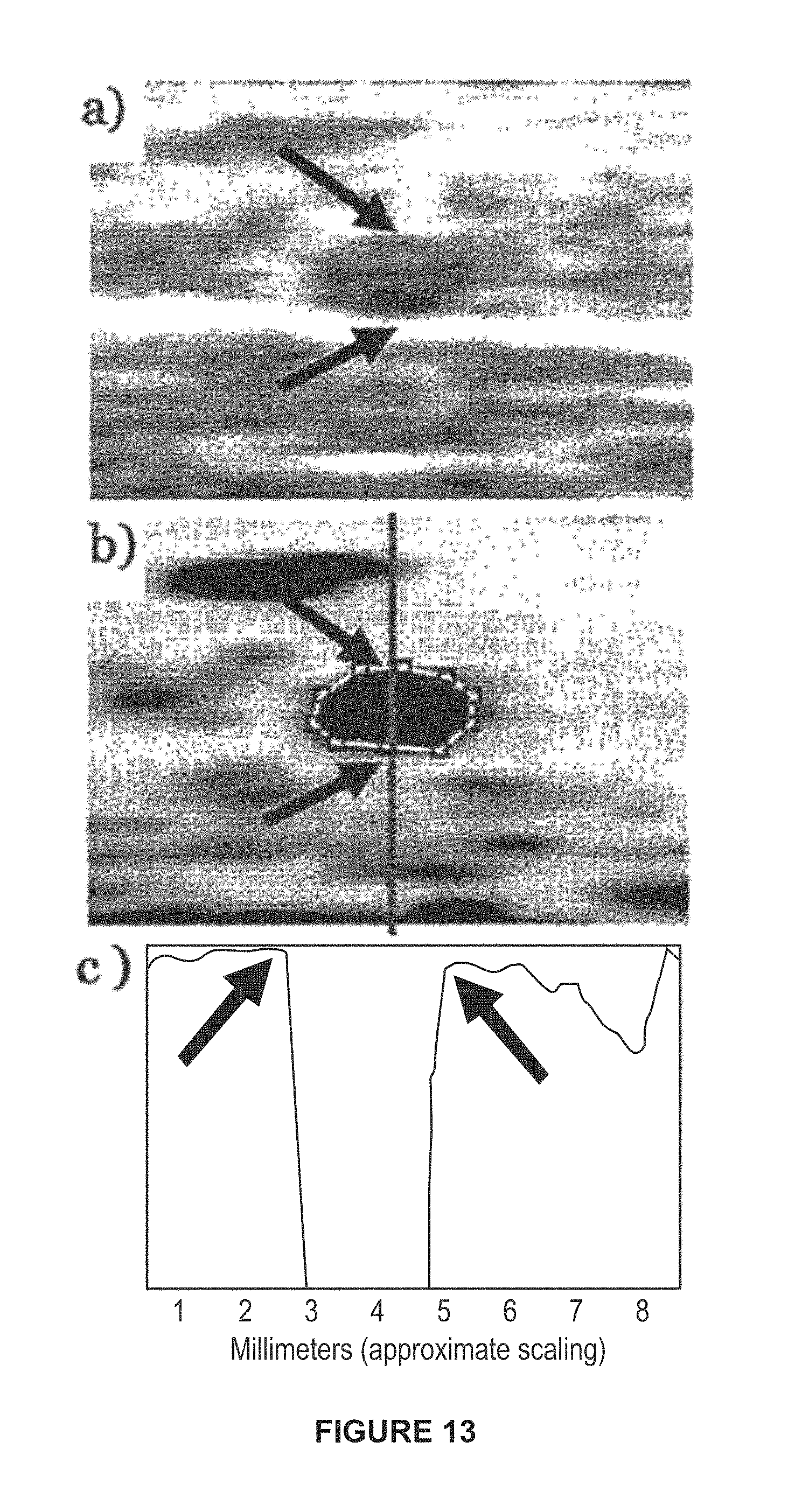
D00021

D00022
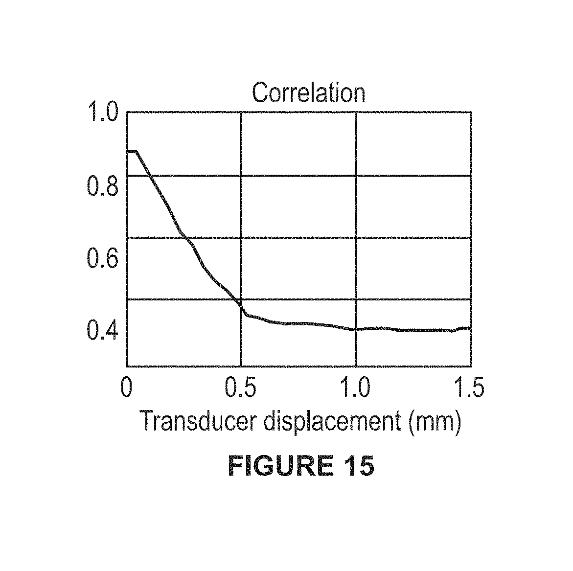
D00023
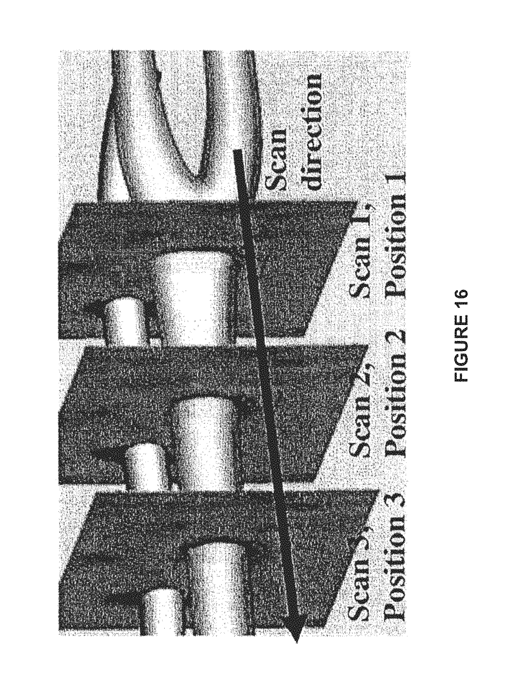
D00024

D00025
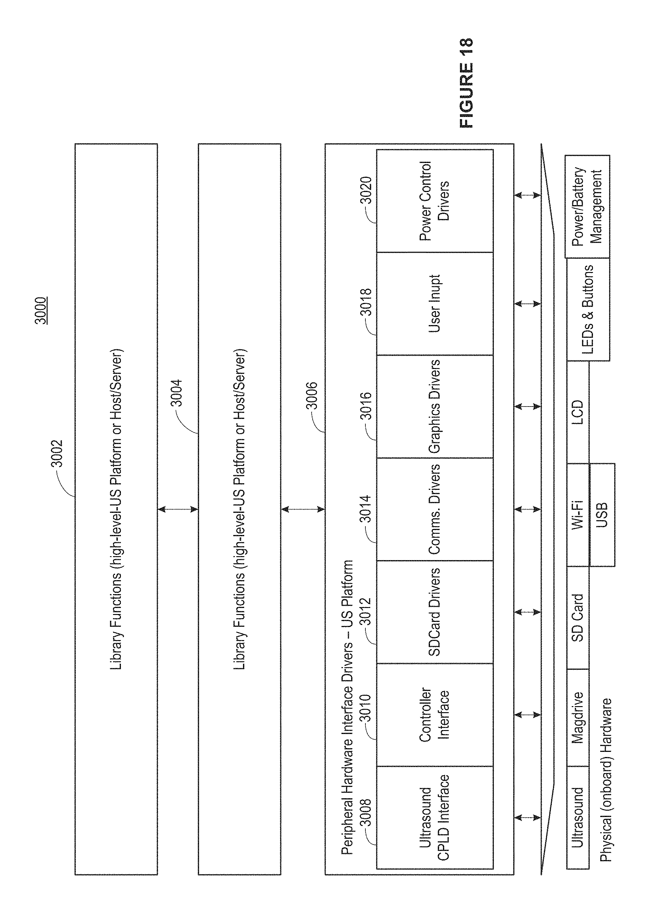
D00026

D00027
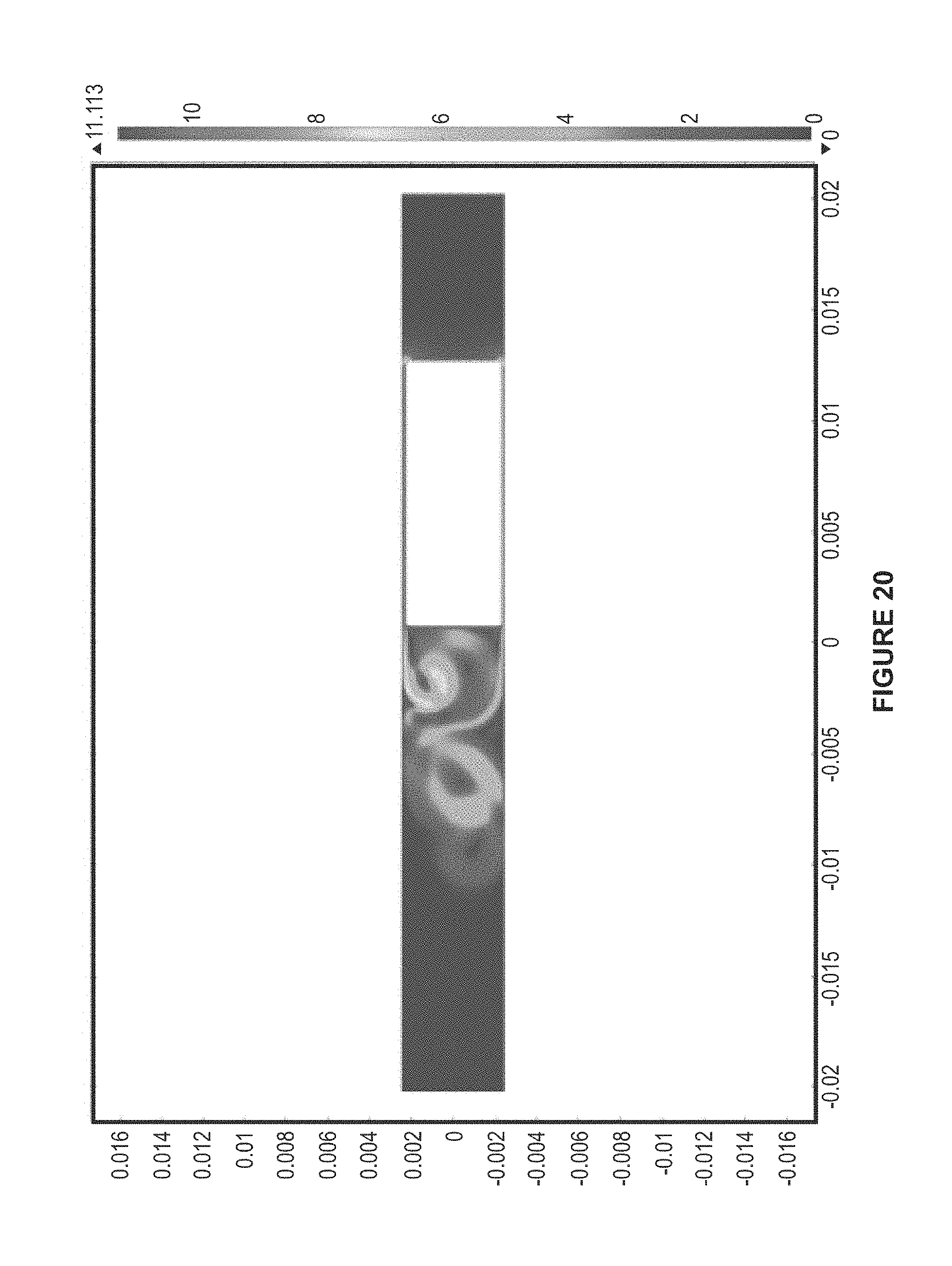
D00028
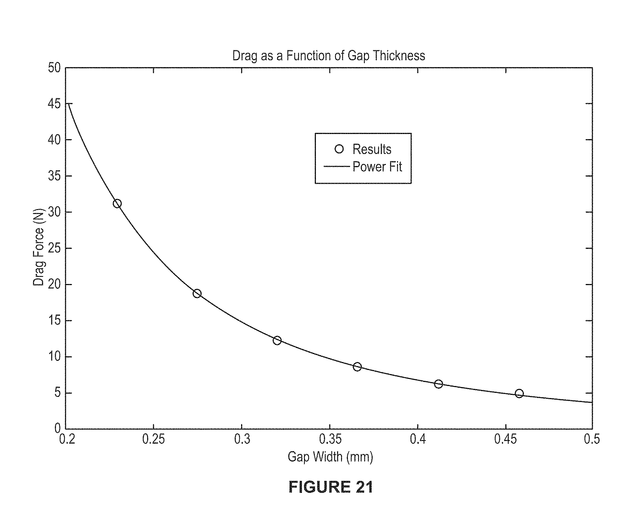
M00001

XML
uspto.report is an independent third-party trademark research tool that is not affiliated, endorsed, or sponsored by the United States Patent and Trademark Office (USPTO) or any other governmental organization. The information provided by uspto.report is based on publicly available data at the time of writing and is intended for informational purposes only.
While we strive to provide accurate and up-to-date information, we do not guarantee the accuracy, completeness, reliability, or suitability of the information displayed on this site. The use of this site is at your own risk. Any reliance you place on such information is therefore strictly at your own risk.
All official trademark data, including owner information, should be verified by visiting the official USPTO website at www.uspto.gov. This site is not intended to replace professional legal advice and should not be used as a substitute for consulting with a legal professional who is knowledgeable about trademark law.