Systems, methods, and computer-readable media for optimizing an electromagnetic navigation system
Morgan , et al. Dec
U.S. patent number 10,517,505 [Application Number 15/337,195] was granted by the patent office on 2019-12-31 for systems, methods, and computer-readable media for optimizing an electromagnetic navigation system. This patent grant is currently assigned to COVIDIEN LP. The grantee listed for this patent is COVIDIEN LP. Invention is credited to Lev A. Koyrakh, Sean M. Morgan.


View All Diagrams
| United States Patent | 10,517,505 |
| Morgan , et al. | December 31, 2019 |
Systems, methods, and computer-readable media for optimizing an electromagnetic navigation system
Abstract
Systems, methods, and computer-readable media for optimizing an electromagnetic navigation system are provided. Multiple test signals corresponding to multiple combinations of phase offset values of a plurality of frequency components, respectively, are generated. Based on the test signals, a table including peak signal amplitudes associated with the respective test signals is generated. A minimum value of the stored peak signal amplitudes is identified in the table. Based on the table, a determination is made as to which combination of phase offset values is associated with the minimum value of the stored peak signal amplitudes. The determined combination of phase offset values is stored in a memory for use, during an electromagnetic navigation procedure, in generating a signal including the frequency components having the determined combination of phase offset values, respectively.
| Inventors: | Morgan; Sean M. (Golden Valley, MN), Koyrakh; Lev A. (Plymouth, MN) | ||||||||||
|---|---|---|---|---|---|---|---|---|---|---|---|
| Applicant: |
|
||||||||||
| Assignee: | COVIDIEN LP (Mansfield,
MA) |
||||||||||
| Family ID: | 62020686 | ||||||||||
| Appl. No.: | 15/337,195 | ||||||||||
| Filed: | October 28, 2016 |
Prior Publication Data
| Document Identifier | Publication Date | |
|---|---|---|
| US 20180116549 A1 | May 3, 2018 | |
| Current U.S. Class: | 1/1 |
| Current CPC Class: | G01C 21/20 (20130101); A61B 5/062 (20130101); G01C 25/00 (20130101) |
| Current International Class: | A61B 5/06 (20060101); G01C 25/00 (20060101); G01C 21/20 (20060101) |
| Field of Search: | ;702/95,108,110 ;324/207.12 ;343/742 ;600/409,424,429 ;606/80 |
References Cited [Referenced By]
U.S. Patent Documents
| 1576781 | March 1926 | Phillips |
| 1735726 | November 1929 | Bornhardt |
| 2407845 | September 1946 | Nemeyer |
| 2650588 | September 1953 | Drew |
| 2697433 | December 1954 | Sehnder |
| 3016899 | January 1962 | Stenvall |
| 3017887 | January 1962 | Heyer |
| 3061936 | November 1962 | Dobbeleer |
| 3073310 | January 1963 | Mocarski |
| 3109588 | November 1963 | Polhemus et al. |
| 3121228 | February 1964 | Kalmus |
| 3294083 | December 1966 | Alderson |
| 3367326 | February 1968 | Frazier |
| 3439256 | April 1969 | Kahne et al. |
| 3519436 | July 1970 | Bauer et al. |
| 3577160 | May 1971 | White |
| 3600625 | August 1971 | Tsuneta et al. |
| 3605725 | September 1971 | Bentov |
| 3614950 | October 1971 | Rabey |
| 3644825 | February 1972 | Davis, Jr. et al. |
| 3674014 | July 1972 | Tillander |
| 3702935 | November 1972 | Carey et al. |
| 3704707 | December 1972 | Halloran |
| 3821469 | June 1974 | Whetstone et al. |
| 3822697 | July 1974 | Komiya |
| 3868565 | February 1975 | Kuipers |
| 3941127 | March 1976 | Froning |
| 3983474 | September 1976 | Kuipers |
| 4017858 | April 1977 | Kuipers |
| 4037592 | July 1977 | Kronner |
| 4052620 | October 1977 | Brunnett |
| 4054881 | October 1977 | Raab |
| 4117337 | September 1978 | Staats |
| 4135184 | January 1979 | Pruzick |
| 4173228 | November 1979 | Van Steenwyk et al. |
| 4182312 | January 1980 | Mushabac |
| 4202349 | May 1980 | Jones |
| 4228799 | October 1980 | Anichkov et al. |
| 4249167 | February 1981 | Purinton et al. |
| 4256112 | March 1981 | Kopf et al. |
| 4262306 | April 1981 | Renner |
| 4287809 | September 1981 | Egli et al. |
| 4298874 | November 1981 | Kuipers |
| 4308530 | December 1981 | Kip et al. |
| 4314251 | February 1982 | Raab |
| 4317078 | February 1982 | Weed et al. |
| 4319136 | March 1982 | Jinkins |
| 4328548 | May 1982 | Crow et al. |
| 4328813 | May 1982 | Ray |
| 4339953 | July 1982 | Iwasaki |
| 4341220 | July 1982 | Perry |
| 4341385 | July 1982 | Doyle et al. |
| 4346384 | August 1982 | Raab |
| 4358856 | November 1982 | Stivender et al. |
| 4368536 | January 1983 | Pfeiler |
| 4394831 | July 1983 | Egli et al. |
| 4396885 | August 1983 | Constant |
| 4396945 | August 1983 | DiMatteo et al. |
| 4403321 | September 1983 | Kruger |
| 4418422 | November 1983 | Richter et al. |
| 4419012 | December 1983 | Stephenson et al. |
| 4422041 | December 1983 | Lienau |
| 4425511 | January 1984 | Brosh |
| 4431005 | February 1984 | McCormick |
| 4447224 | May 1984 | DeCant, Jr. et al. |
| 4447462 | May 1984 | Tafuri et al. |
| 4485815 | December 1984 | Amplatz et al. |
| 4506676 | March 1985 | Duska |
| 4543959 | October 1985 | Sepponen |
| 4548208 | October 1985 | Niemi |
| 4571834 | February 1986 | Fraser et al. |
| 4572198 | February 1986 | Codrington |
| 4583538 | April 1986 | Onik et al. |
| 4584577 | April 1986 | Temple |
| 4586491 | May 1986 | Carpenter |
| 4587975 | May 1986 | Salo et al. |
| 4608977 | September 1986 | Brown |
| 4613866 | September 1986 | Blood |
| 4617925 | October 1986 | Laitinen |
| 4618978 | October 1986 | Cosman |
| 4621628 | November 1986 | Brudermann |
| 4625718 | December 1986 | Olerud et al. |
| 4638798 | January 1987 | Shelden et al. |
| 4642786 | February 1987 | Hansen |
| 4645343 | February 1987 | Stockdale et al. |
| 4649504 | March 1987 | Krouglicof et al. |
| 4651732 | March 1987 | Frederick |
| 4653509 | March 1987 | Oloff et al. |
| 4659971 | April 1987 | Suzuki et al. |
| 4660970 | April 1987 | Ferrano |
| 4673352 | June 1987 | Hansen |
| 4686695 | August 1987 | Macovski |
| 4688037 | August 1987 | Krieg |
| 4696544 | September 1987 | Costella |
| 4697595 | October 1987 | Breyer et al. |
| 4701049 | October 1987 | Beckman et al. |
| 4704602 | November 1987 | Asbrink |
| 4705395 | November 1987 | Hageniers |
| 4705401 | November 1987 | Addleman et al. |
| 4706665 | November 1987 | Gouda |
| 4709156 | November 1987 | Murphy et al. |
| 4710708 | December 1987 | Rorden et al. |
| 4719419 | January 1988 | Dawley |
| 4722056 | January 1988 | Roberts et al. |
| 4722336 | February 1988 | Kim et al. |
| 4723544 | February 1988 | Moore et al. |
| 4726355 | February 1988 | Okada |
| 4727565 | February 1988 | Ericson |
| RE32619 | March 1988 | Damadian |
| 4733969 | March 1988 | Case et al. |
| 4737032 | April 1988 | Addleman et al. |
| 4737794 | April 1988 | Jones |
| 4737921 | April 1988 | Goldwasser et al. |
| 4742356 | May 1988 | Kuipers |
| 4742815 | May 1988 | Ninan et al. |
| 4743770 | May 1988 | Lee |
| 4743771 | May 1988 | Sacks et al. |
| 4745290 | May 1988 | Frankel et al. |
| 4750487 | June 1988 | Zanetti |
| 4753528 | June 1988 | Hines et al. |
| 4761072 | August 1988 | Pryor |
| 4764016 | August 1988 | Johansson |
| 4771787 | September 1988 | Wurster et al. |
| 4779212 | October 1988 | Levy |
| 4782239 | November 1988 | Hirose et al. |
| 4784117 | November 1988 | Miyazaki |
| 4788481 | November 1988 | Niwa |
| 4791934 | December 1988 | Brunnett |
| 4793355 | December 1988 | Crum et al. |
| 4794262 | December 1988 | Sato et al. |
| 4797907 | January 1989 | Anderton |
| 4803976 | February 1989 | Frigg et al. |
| 4804261 | February 1989 | Kirschen |
| 4805615 | February 1989 | Carol |
| 4809694 | March 1989 | Ferrara |
| 4821200 | April 1989 | Oberg |
| 4821206 | April 1989 | Arora |
| 4821731 | April 1989 | Martinelli et al. |
| 4822163 | April 1989 | Schmidt |
| 4825091 | April 1989 | Breyer et al. |
| 4829250 | May 1989 | Rotier |
| 4829373 | May 1989 | Leberl et al. |
| 4836778 | June 1989 | Baumrind et al. |
| 4838265 | June 1989 | Cosman et al. |
| 4841967 | June 1989 | Chang et al. |
| 4845771 | July 1989 | Wislocki et al. |
| 4849692 | July 1989 | Blood |
| 4860331 | August 1989 | Williams et al. |
| 4862893 | September 1989 | Martinelli |
| 4869247 | September 1989 | Howard, III et al. |
| 4875165 | October 1989 | Fencil et al. |
| 4875478 | October 1989 | Chen |
| 4884566 | December 1989 | Mountz et al. |
| 4889526 | December 1989 | Rauscher et al. |
| 4896673 | January 1990 | Rose et al. |
| 4905698 | March 1990 | Strohl, Jr. et al. |
| 4923459 | May 1990 | Nambu |
| 4931056 | June 1990 | Ghajar et al. |
| 4945305 | July 1990 | Blood |
| 4945912 | August 1990 | Langberg |
| 4945914 | August 1990 | Allen |
| 4951653 | August 1990 | Fry et al. |
| 4955891 | September 1990 | Carol |
| 4961422 | October 1990 | Marchosky et al. |
| 4977655 | December 1990 | Martinelli |
| 4989608 | February 1991 | Ratner |
| 4991579 | February 1991 | Allen |
| 5002058 | March 1991 | Martinelli |
| 5005592 | April 1991 | Cartmell |
| 5013047 | May 1991 | Schwab |
| 5013317 | May 1991 | Cole et al. |
| 5016639 | May 1991 | Allen |
| 5017139 | May 1991 | Mushabac |
| 5023102 | June 1991 | Given, Jr. |
| 5027818 | July 1991 | Bova et al. |
| 5030196 | July 1991 | Inoue |
| 5030222 | July 1991 | Calandruccio et al. |
| 5031203 | July 1991 | Trecha |
| RE33662 | August 1991 | Blair et al. |
| 5042486 | August 1991 | Pfeiler et al. |
| 5047036 | September 1991 | Koutrouvelis |
| 5050608 | September 1991 | Watanabe et al. |
| 5054492 | October 1991 | Scribner et al. |
| 5057095 | October 1991 | Fabian |
| 5059789 | October 1991 | Salcudean |
| 5070462 | December 1991 | Chau |
| 5078140 | January 1992 | Kwoh |
| 5079699 | January 1992 | Tuy et al. |
| 5082286 | January 1992 | Ryan et al. |
| 5086401 | February 1992 | Glassman et al. |
| 5088928 | February 1992 | Chan |
| 5094241 | March 1992 | Allen |
| 5097839 | March 1992 | Allen |
| 5098426 | March 1992 | Sklar |
| 5099845 | March 1992 | Besz et al. |
| 5099846 | March 1992 | Hardy |
| 5104393 | April 1992 | Isner et al. |
| 5105829 | April 1992 | Fabian et al. |
| 5107839 | April 1992 | Houdek et al. |
| 5107843 | April 1992 | Aarnio et al. |
| 5107862 | April 1992 | Fabian et al. |
| 5109194 | April 1992 | Cantaloube |
| 5119817 | June 1992 | Allen |
| 5127408 | July 1992 | Parsons et al. |
| 5129654 | July 1992 | Bogner |
| 5142930 | September 1992 | Allen et al. |
| 5143076 | September 1992 | Hardy et al. |
| 5152277 | October 1992 | Honda et al. |
| 5152288 | October 1992 | Hoenig et al. |
| 5160337 | November 1992 | Cosman |
| 5161536 | November 1992 | Vilkomerson et al. |
| 5178130 | January 1993 | Kaiya |
| 5178164 | January 1993 | Allen |
| 5178621 | January 1993 | Cook et al. |
| 5186174 | February 1993 | Schlondorff et al. |
| 5187475 | February 1993 | Wagener et al. |
| 5188126 | February 1993 | Fabian et al. |
| 5188368 | February 1993 | Ryan |
| 5190059 | March 1993 | Fabian et al. |
| 5190285 | March 1993 | Levy et al. |
| 5193106 | March 1993 | DeSena |
| 5196928 | March 1993 | Karasawa et al. |
| 5197476 | March 1993 | Nowacki et al. |
| 5197965 | March 1993 | Cherry et al. |
| 5198768 | March 1993 | Keren |
| 5198877 | March 1993 | Schulz |
| 5203337 | April 1993 | Feldman |
| 5207688 | May 1993 | Carol |
| 5211164 | May 1993 | Allen |
| 5211165 | May 1993 | Dumoulin et al. |
| 5211176 | May 1993 | Ishiguro et al. |
| 5212720 | May 1993 | Landi et al. |
| 5214615 | May 1993 | Bauer |
| 5219351 | June 1993 | Teubner et al. |
| 5222499 | June 1993 | Allen et al. |
| 5224049 | June 1993 | Mushabac |
| 5228442 | July 1993 | Imran |
| 5230338 | July 1993 | Allen et al. |
| 5230623 | July 1993 | Guthrie et al. |
| 5233990 | August 1993 | Barnea |
| 5237996 | August 1993 | Waldman et al. |
| 5249581 | October 1993 | Horbal et al. |
| 5251127 | October 1993 | Raab |
| 5251635 | October 1993 | Dumoulin et al. |
| 5253647 | October 1993 | Takahashi et al. |
| 5255680 | October 1993 | Darrow et al. |
| 5257636 | November 1993 | White |
| 5257998 | November 1993 | Ota et al. |
| 5261404 | November 1993 | Mick et al. |
| 5262722 | November 1993 | Hedengren et al. |
| 5265610 | November 1993 | Darrow et al. |
| 5265611 | November 1993 | Hoenig et al. |
| 5269759 | December 1993 | Hernandez et al. |
| 5271400 | December 1993 | Dumoulin et al. |
| 5273025 | December 1993 | Sakiyama et al. |
| 5274551 | December 1993 | Corby, Jr. |
| 5279309 | January 1994 | Taylor et al. |
| 5285787 | February 1994 | Machida |
| 5291199 | March 1994 | Overman et al. |
| 5291889 | March 1994 | Kenet et al. |
| 5295483 | March 1994 | Nowacki et al. |
| 5297549 | March 1994 | Beatty et al. |
| 5299253 | March 1994 | Wessels |
| 5299254 | March 1994 | Dancer et al. |
| 5299288 | March 1994 | Glassman et al. |
| 5300080 | April 1994 | Clayman et al. |
| 5301061 | April 1994 | Nakada et al. |
| 5305091 | April 1994 | Gelbart et al. |
| 5305203 | April 1994 | Raab |
| 5306271 | April 1994 | Zinreich et al. |
| 5307072 | April 1994 | Jones, Jr. |
| 5307816 | May 1994 | Hashimoto et al. |
| 5309913 | May 1994 | Kormos et al. |
| 5315630 | May 1994 | Sturm et al. |
| 5316024 | May 1994 | Hirschi et al. |
| 5318025 | June 1994 | Dumoulin et al. |
| 5320111 | June 1994 | Livingston |
| 5325728 | July 1994 | Zimmerman et al. |
| 5325873 | July 1994 | Hirschi et al. |
| 5327889 | July 1994 | Imran |
| 5329944 | July 1994 | Fabian et al. |
| 5330485 | July 1994 | Clayman et al. |
| 5333168 | July 1994 | Fernandes et al. |
| 5341807 | August 1994 | Nardella |
| 5347289 | September 1994 | Elhardt |
| 5353795 | October 1994 | Souza et al. |
| 5353800 | October 1994 | Pohndorf et al. |
| 5353807 | October 1994 | DeMarco |
| 5357253 | October 1994 | Van Etten et al. |
| 5359417 | October 1994 | Muller et al. |
| 5368030 | November 1994 | Zinreich et al. |
| 5371778 | December 1994 | Yanof et al. |
| 5375596 | December 1994 | Twiss et al. |
| 5376795 | December 1994 | Hasegawa et al. |
| 5377678 | January 1995 | Dumoulin et al. |
| 5383454 | January 1995 | Bucholz |
| 5383852 | January 1995 | Stevens-Wright |
| 5385146 | January 1995 | Goldreyer |
| 5385148 | January 1995 | Lesh et al. |
| 5386828 | February 1995 | Owens et al. |
| 5389073 | February 1995 | Imran |
| 5389101 | February 1995 | Heilbrun et al. |
| 5391199 | February 1995 | Ben-Haim |
| 5394457 | February 1995 | Leibinger et al. |
| 5394875 | March 1995 | Lewis et al. |
| 5397321 | March 1995 | Houser et al. |
| 5397329 | March 1995 | Allen |
| 5398684 | March 1995 | Hardy |
| 5398691 | March 1995 | Martin et al. |
| 5399146 | March 1995 | Nowacki et al. |
| 5400384 | March 1995 | Fernandes et al. |
| 5400771 | March 1995 | Pirak et al. |
| 5402801 | April 1995 | Taylor |
| 5405346 | April 1995 | Grundy et al. |
| 5408409 | April 1995 | Glassman et al. |
| 5409000 | April 1995 | Imran |
| 5412414 | May 1995 | Ast et al. |
| 5413573 | May 1995 | Koivukangas |
| 5417210 | May 1995 | Funda et al. |
| 5419325 | May 1995 | Dumoulin et al. |
| 5423334 | June 1995 | Jordan |
| 5425367 | June 1995 | Shapiro et al. |
| 5425382 | June 1995 | Golden et al. |
| 5426683 | June 1995 | O'Farrell, Jr. et al. |
| 5426687 | June 1995 | Goodall et al. |
| 5427097 | June 1995 | Depp |
| 5429132 | July 1995 | Guy et al. |
| 5433198 | July 1995 | Desai |
| 5435573 | July 1995 | Oakford |
| RE35025 | August 1995 | Anderton |
| 5437277 | August 1995 | Dumoulin et al. |
| 5443066 | August 1995 | Dumoulin et al. |
| 5443489 | August 1995 | Ben-Haim |
| 5444756 | August 1995 | Pai et al. |
| 5445144 | August 1995 | Wodicka et al. |
| 5445150 | August 1995 | Dumoulin et al. |
| 5445166 | August 1995 | Taylor |
| 5446548 | August 1995 | Gerig et al. |
| 5447154 | September 1995 | Cinquin et al. |
| 5447156 | September 1995 | Dumoulin et al. |
| 5448610 | September 1995 | Yamamoto et al. |
| 5453686 | September 1995 | Anderson |
| 5456254 | October 1995 | Pietroski et al. |
| 5456664 | October 1995 | Heinzelman et al. |
| 5456689 | October 1995 | Kresch et al. |
| 5456718 | October 1995 | Szymaitis |
| 5457641 | October 1995 | Zimmer et al. |
| 5458718 | October 1995 | Venkitachalam |
| 5464446 | November 1995 | Dreessen et al. |
| 5469847 | November 1995 | Zinreich et al. |
| 5472441 | December 1995 | Edwards et al. |
| 5476100 | December 1995 | Galel |
| 5476495 | December 1995 | Kordis et al. |
| 5478341 | December 1995 | Cook et al. |
| 5478343 | December 1995 | Ritter |
| 5480422 | January 1996 | Ben-Haim |
| 5480439 | January 1996 | Bisek et al. |
| 5483961 | January 1996 | Kelly et al. |
| 5485849 | January 1996 | Panescu et al. |
| 5487391 | January 1996 | Panescu |
| 5487729 | January 1996 | Avellanet et al. |
| 5487757 | January 1996 | Truckai et al. |
| 5489256 | February 1996 | Adair |
| 5490196 | February 1996 | Rudich et al. |
| 5492131 | February 1996 | Galel |
| 5492713 | February 1996 | Sommermeyer |
| 5493517 | February 1996 | Frazier |
| 5494034 | February 1996 | Schlondorff et al. |
| 5503416 | April 1996 | Aoki et al. |
| 5513637 | May 1996 | Twiss et al. |
| 5514146 | May 1996 | Lam et al. |
| 5515160 | May 1996 | Schulz et al. |
| 5515853 | May 1996 | Smith et al. |
| 5517990 | May 1996 | Kalfas et al. |
| 5520059 | May 1996 | Garshelis |
| 5522814 | June 1996 | Bernaz |
| 5522815 | June 1996 | Durgin, Jr. et al. |
| 5531227 | July 1996 | Schneider |
| 5531520 | July 1996 | Grimson et al. |
| 5531686 | July 1996 | Lundquist et al. |
| 5542938 | August 1996 | Avellanet et al. |
| 5543951 | August 1996 | Moehrmann |
| 5545200 | August 1996 | West et al. |
| 5546940 | August 1996 | Panescu et al. |
| 5546949 | August 1996 | Frazin et al. |
| 5546951 | August 1996 | Ben-Haim |
| 5551429 | September 1996 | Fitzpatrick et al. |
| 5555883 | September 1996 | Avitall |
| 5558091 | September 1996 | Acker et al. |
| 5566681 | October 1996 | Manwaring et al. |
| 5568384 | October 1996 | Robb et al. |
| 5568809 | October 1996 | Ben-Haim |
| 5571083 | November 1996 | Lemelson |
| 5572999 | November 1996 | Funda et al. |
| 5573533 | November 1996 | Strul |
| 5575794 | November 1996 | Walus et al. |
| 5575798 | November 1996 | Koutrouvelis |
| 5577991 | November 1996 | Akui et al. |
| 5583909 | December 1996 | Hanover |
| 5588033 | December 1996 | Yeung |
| 5588430 | December 1996 | Bova et al. |
| 5590215 | December 1996 | Allen |
| 5592939 | January 1997 | Martinelli |
| 5595193 | January 1997 | Walus et al. |
| 5596228 | January 1997 | Anderton et al. |
| 5599305 | February 1997 | Hermann et al. |
| 5600330 | February 1997 | Blood |
| 5603318 | February 1997 | Heilbrun et al. |
| 5606975 | March 1997 | Liang et al. |
| 5611025 | March 1997 | Lorensen et al. |
| 5617462 | April 1997 | Spratt |
| 5617857 | April 1997 | Chader et al. |
| 5619261 | April 1997 | Anderton |
| 5620734 | April 1997 | Wesdorp et al. |
| 5622169 | April 1997 | Golden et al. |
| 5622170 | April 1997 | Schulz |
| 5627873 | May 1997 | Hanover et al. |
| 5628315 | May 1997 | Vilsmeier et al. |
| 5630431 | May 1997 | Taylor |
| 5636634 | June 1997 | Kordis et al. |
| 5636644 | June 1997 | Hart et al. |
| 5638819 | June 1997 | Manwaring et al. |
| 5640170 | June 1997 | Anderson |
| 5642395 | June 1997 | Anderton et al. |
| 5643175 | July 1997 | Adair |
| 5643268 | July 1997 | Vilsmeier et al. |
| 5645065 | July 1997 | Shapiro et al. |
| 5646524 | July 1997 | Gilboa |
| 5646525 | July 1997 | Gilboa |
| 5647361 | July 1997 | Damadian |
| 5651047 | July 1997 | Moorman et al. |
| 5660865 | August 1997 | Pedersen et al. |
| 5662108 | September 1997 | Budd et al. |
| 5662111 | September 1997 | Cosman |
| 5664001 | September 1997 | Tachibana et al. |
| 5674296 | October 1997 | Bryan et al. |
| 5676673 | October 1997 | Ferre et al. |
| 5681260 | October 1997 | Ueda et al. |
| 5682165 | October 1997 | Lewis et al. |
| 5682886 | November 1997 | Delp et al. |
| 5682890 | November 1997 | Kormos et al. |
| 5690108 | November 1997 | Chakeres |
| 5694945 | December 1997 | Ben-Haim |
| 5695500 | December 1997 | Taylor et al. |
| 5695501 | December 1997 | Carol et al. |
| 5696500 | December 1997 | Diem |
| 5697377 | December 1997 | Wittkampf |
| 5701898 | December 1997 | Adam et al. |
| 5702406 | December 1997 | Vilsmeier et al. |
| 5711299 | January 1998 | Manwaring et al. |
| 5713369 | February 1998 | Tao et al. |
| 5713853 | February 1998 | Clark et al. |
| 5713946 | February 1998 | Ben-Haim |
| 5715822 | February 1998 | Watkins et al. |
| 5715836 | February 1998 | Kliegis et al. |
| 5718241 | February 1998 | Ben-Haim et al. |
| 5727552 | March 1998 | Ryan |
| 5727553 | March 1998 | Saad |
| 5729129 | March 1998 | Acker |
| 5730129 | March 1998 | Darrow et al. |
| 5730130 | March 1998 | Fitzpatrick et al. |
| 5732703 | March 1998 | Kalfas et al. |
| 5735278 | April 1998 | Hoult et al. |
| 5738096 | April 1998 | Ben-Haim |
| 5740802 | April 1998 | Nafis et al. |
| 5740808 | April 1998 | Panescu et al. |
| 5741214 | April 1998 | Ouchi et al. |
| 5741320 | April 1998 | Thornton et al. |
| 5742394 | April 1998 | Hansen |
| 5744802 | April 1998 | Muehllehner et al. |
| 5744953 | April 1998 | Hansen |
| 5748767 | May 1998 | Raab |
| 5749362 | May 1998 | Funda et al. |
| 5749835 | May 1998 | Glantz |
| 5752513 | May 1998 | Acker et al. |
| 5752518 | May 1998 | McGee et al. |
| 5755725 | May 1998 | Druais |
| RE35816 | June 1998 | Schulz |
| 5758667 | June 1998 | Slettenmark |
| 5760335 | June 1998 | Gilboa |
| 5762064 | June 1998 | Polvani |
| 5767669 | June 1998 | Hansen et al. |
| 5767699 | June 1998 | Bosnyak et al. |
| 5767960 | June 1998 | Orman |
| 5769789 | June 1998 | Wang et al. |
| 5769843 | June 1998 | Abela et al. |
| 5769861 | June 1998 | Vilsmeier |
| 5772594 | June 1998 | Barrick |
| 5775322 | July 1998 | Silverstein et al. |
| 5776050 | July 1998 | Chen et al. |
| 5776064 | July 1998 | Kalfas et al. |
| 5782765 | July 1998 | Jonkman |
| 5782828 | July 1998 | Chen et al. |
| 5787886 | August 1998 | Kelly et al. |
| 5792055 | August 1998 | McKinnon |
| 5795294 | August 1998 | Luber et al. |
| 5797849 | August 1998 | Vesely et al. |
| 5799055 | August 1998 | Peshkin et al. |
| 5799099 | August 1998 | Wang et al. |
| 5800352 | September 1998 | Ferre et al. |
| 5800535 | September 1998 | Howard, III |
| 5802719 | September 1998 | O'Farrell, Jr. et al. |
| 5803084 | September 1998 | Olson |
| 5803089 | September 1998 | Ferre et al. |
| 5807252 | September 1998 | Hassfeld et al. |
| 5810008 | September 1998 | Dekel et al. |
| 5810728 | September 1998 | Kuhn |
| 5810735 | September 1998 | Halperin et al. |
| 5820553 | October 1998 | Hughes |
| 5820591 | October 1998 | Thompson et al. |
| 5823192 | October 1998 | Kalend et al. |
| 5823958 | October 1998 | Truppe |
| 5828725 | October 1998 | Levinson |
| 5828770 | October 1998 | Leis et al. |
| 5829444 | November 1998 | Ferre et al. |
| 5831260 | November 1998 | Hansen |
| 5833608 | November 1998 | Acker |
| 5834759 | November 1998 | Glossop |
| 5836954 | November 1998 | Heilbrun et al. |
| 5837001 | November 1998 | Mackey |
| 5840024 | November 1998 | Taniguchi et al. |
| 5840025 | November 1998 | Ben-Haim |
| 5842984 | December 1998 | Avitall |
| 5843051 | December 1998 | Adams et al. |
| 5843076 | December 1998 | Webster, Jr. et al. |
| 5846183 | December 1998 | Chilcoat |
| 5848967 | December 1998 | Cosman |
| 5851183 | December 1998 | Bucholz |
| 5853327 | December 1998 | Gilboa |
| 5857997 | January 1999 | Cimino et al. |
| 5865726 | February 1999 | Katsurada et al. |
| 5865846 | February 1999 | Bryan et al. |
| 5868673 | February 1999 | Vesely |
| 5868674 | February 1999 | Glowinski et al. |
| 5868675 | February 1999 | Henrion et al. |
| 5871445 | February 1999 | Bucholz |
| 5871455 | February 1999 | Ueno |
| 5871487 | February 1999 | Warner et al. |
| 5871523 | February 1999 | Fleischman et al. |
| 5873822 | February 1999 | Ferre et al. |
| 5882304 | March 1999 | Ehnholm et al. |
| 5884410 | March 1999 | Prinz |
| 5889834 | March 1999 | Vilsmeier et al. |
| 5891034 | April 1999 | Bucholz |
| 5891134 | April 1999 | Goble et al. |
| 5891157 | April 1999 | Day et al. |
| 5893885 | April 1999 | Webster, Jr. |
| 5899860 | May 1999 | Pfeiffer et al. |
| 5902239 | May 1999 | Buurman |
| 5902324 | May 1999 | Thompson et al. |
| 5904691 | May 1999 | Barnett et al. |
| 5907395 | May 1999 | Schulz et al. |
| 5909476 | June 1999 | Cheng et al. |
| 5913820 | June 1999 | Bladen et al. |
| 5916210 | June 1999 | Winston |
| 5919147 | July 1999 | Jain |
| 5919188 | July 1999 | Shearon et al. |
| 5920395 | July 1999 | Schulz |
| 5921992 | July 1999 | Costales et al. |
| 5923727 | July 1999 | Navab |
| 5928248 | July 1999 | Acker |
| 5930329 | July 1999 | Navab |
| 5935160 | August 1999 | Auricchio et al. |
| 5938585 | August 1999 | Donofrio |
| 5938602 | August 1999 | Lloyd |
| 5938603 | August 1999 | Ponzi |
| 5938694 | August 1999 | Jaraczewski et al. |
| 5941251 | August 1999 | Panescu et al. |
| 5944023 | August 1999 | Johnson et al. |
| 5947925 | September 1999 | Ashiya et al. |
| 5947980 | September 1999 | Jensen et al. |
| 5947981 | September 1999 | Cosman |
| 5950629 | September 1999 | Taylor et al. |
| 5951461 | September 1999 | Nyo et al. |
| 5951475 | September 1999 | Gueziec et al. |
| 5951571 | September 1999 | Audette |
| 5954647 | September 1999 | Bova |
| 5954649 | September 1999 | Chia et al. |
| 5954796 | September 1999 | McCarty et al. |
| 5957844 | September 1999 | Dekel et al. |
| 5966090 | October 1999 | McEwan |
| 5967980 | October 1999 | Ferre et al. |
| 5967982 | October 1999 | Barnett |
| 5968047 | October 1999 | Reed |
| 5971997 | October 1999 | Guthrie et al. |
| 5976127 | November 1999 | Lax |
| 5976156 | November 1999 | Taylor et al. |
| 5980504 | November 1999 | Sharkey et al. |
| 5980535 | November 1999 | Barnett et al. |
| 5983126 | November 1999 | Wittkampf |
| 5987349 | November 1999 | Schulz |
| 5987960 | November 1999 | Messner et al. |
| 5999837 | December 1999 | Messner et al. |
| 5999840 | December 1999 | Grimson et al. |
| 6001130 | December 1999 | Bryan et al. |
| 6004269 | December 1999 | Crowley et al. |
| 6006126 | December 1999 | Cosman |
| 6006127 | December 1999 | Van Der Brug et al. |
| 6013087 | January 2000 | Adams et al. |
| 6014580 | January 2000 | Blume et al. |
| 6016439 | January 2000 | Acker |
| 6019724 | February 2000 | Gronningsaeter et al. |
| 6019725 | February 2000 | Vesely et al. |
| 6019728 | February 2000 | Iwata et al. |
| 6022578 | February 2000 | Miller |
| 6024695 | February 2000 | Taylor et al. |
| 6024739 | February 2000 | Ponzi et al. |
| 6032675 | March 2000 | Rubinsky |
| 6035229 | March 2000 | Silverstein et al. |
| 6050724 | April 2000 | Schmitz et al. |
| 6059718 | May 2000 | Taniguchi et al. |
| 6061588 | May 2000 | Thornton et al. |
| 6063022 | May 2000 | Ben-Haim |
| 6064390 | May 2000 | Sagar et al. |
| 6071288 | June 2000 | Carol et al. |
| 6073043 | June 2000 | Schneider |
| 6076008 | June 2000 | Bucholz |
| 6077257 | June 2000 | Edwards et al. |
| 6096036 | August 2000 | Bowe et al. |
| 6096050 | August 2000 | Audette |
| 6104294 | August 2000 | Andersson et al. |
| 6104944 | August 2000 | Martinelli |
| 6106517 | August 2000 | Zupkas |
| 6112111 | August 2000 | Glantz |
| 6115626 | September 2000 | Whayne et al. |
| 6117476 | September 2000 | Eger et al. |
| 6118845 | September 2000 | Simon et al. |
| 6122538 | September 2000 | Sliwa, Jr. et al. |
| 6122541 | September 2000 | Cosman et al. |
| 6123979 | September 2000 | Hepburn et al. |
| 6131396 | October 2000 | Duerr et al. |
| 6139183 | October 2000 | Graumann |
| 6147480 | November 2000 | Osadchy et al. |
| 6149592 | November 2000 | Yanof et al. |
| 6156067 | December 2000 | Bryan et al. |
| 6161032 | December 2000 | Acker |
| 6165181 | December 2000 | Heilbrun et al. |
| 6167296 | December 2000 | Shahidi |
| 6171303 | January 2001 | Ben-Haim et al. |
| 6172499 | January 2001 | Ashe |
| 6175756 | January 2001 | Ferre et al. |
| 6178345 | January 2001 | Vilsmeier et al. |
| 6179809 | January 2001 | Khairkhahan et al. |
| 6183444 | February 2001 | Glines et al. |
| 6188355 | February 2001 | Gilboa |
| 6192280 | February 2001 | Sommer et al. |
| 6194639 | February 2001 | Botella et al. |
| 6201387 | March 2001 | Govari |
| 6203493 | March 2001 | Ben-Haim |
| 6203497 | March 2001 | Dekel et al. |
| 6208884 | March 2001 | Kumar et al. |
| 6210362 | April 2001 | Ponzi |
| 6211666 | April 2001 | Acker |
| 6213995 | April 2001 | Steen et al. |
| 6213998 | April 2001 | Shen et al. |
| 6216027 | April 2001 | Willis et al. |
| 6216029 | April 2001 | Paltieli |
| 6223067 | April 2001 | Vilsmeier et al. |
| 6226543 | May 2001 | Gilboa et al. |
| 6233476 | May 2001 | Strommer et al. |
| 6236875 | May 2001 | Bucholz et al. |
| 6245020 | June 2001 | Moore et al. |
| 6246231 | June 2001 | Ashe |
| 6246784 | June 2001 | Summers et al. |
| 6246898 | June 2001 | Vesely et al. |
| 6246899 | June 2001 | Chia et al. |
| 6248074 | June 2001 | Ohno et al. |
| 6253770 | July 2001 | Acker et al. |
| 6259942 | July 2001 | Westermann et al. |
| 6264654 | July 2001 | Swartz et al. |
| 6272371 | August 2001 | Shlomo |
| 6273896 | August 2001 | Franck et al. |
| 6285902 | September 2001 | Kienzle, III et al. |
| 6298262 | October 2001 | Franck et al. |
| 6304769 | October 2001 | Arenson et al. |
| 6306097 | October 2001 | Park et al. |
| 6314310 | November 2001 | Ben-Haim et al. |
| 6319250 | November 2001 | Falwell et al. |
| 6331116 | December 2001 | Kaufman et al. |
| 6331156 | December 2001 | Haefele et al. |
| 6332089 | December 2001 | Acker et al. |
| 6335617 | January 2002 | Osadchy et al. |
| 6341231 | January 2002 | Ferre et al. |
| 6345112 | February 2002 | Summers et al. |
| 6346940 | February 2002 | Fukunaga |
| 6351513 | February 2002 | Bani-Hashemi et al. |
| 6351659 | February 2002 | Vilsmeier |
| 6366799 | April 2002 | Acker et al. |
| 6373240 | April 2002 | Govari |
| 6380732 | April 2002 | Gilboa |
| 6381485 | April 2002 | Hunter et al. |
| 6383144 | May 2002 | Mooney et al. |
| 6405072 | June 2002 | Cosman |
| 6423009 | July 2002 | Downey et al. |
| 6424856 | July 2002 | Vilsmeier et al. |
| 6427314 | August 2002 | Acker |
| 6428547 | August 2002 | Vilsmeier et al. |
| 6434415 | August 2002 | Foley et al. |
| 6437567 | August 2002 | Schenck et al. |
| 6443894 | September 2002 | Sumanaweera et al. |
| 6445943 | September 2002 | Ferre et al. |
| 6447504 | September 2002 | Ben-Haim et al. |
| 6453190 | September 2002 | Acker et al. |
| 6468265 | October 2002 | Evans et al. |
| 6470207 | October 2002 | Simon et al. |
| 6473635 | October 2002 | Rasche |
| 6474341 | November 2002 | Hunter et al. |
| 6478802 | November 2002 | Kienzle, III et al. |
| 6484049 | November 2002 | Seeley et al. |
| 6484118 | November 2002 | Govari |
| 6490475 | December 2002 | Seeley et al. |
| 6493573 | December 2002 | Martinelli et al. |
| 6498477 | December 2002 | Govari et al. |
| 6498944 | December 2002 | Ben-Haim et al. |
| 6499488 | December 2002 | Hunter et al. |
| 6516046 | February 2003 | Frohlich et al. |
| 6517534 | February 2003 | McGovern et al. |
| 6527443 | March 2003 | Vilsmeier et al. |
| 6551325 | April 2003 | Neubauer et al. |
| 6558333 | May 2003 | Gilboa et al. |
| 6574492 | June 2003 | Ben-Haim et al. |
| 6574498 | June 2003 | Gilboa |
| 6580938 | June 2003 | Acker |
| 6584174 | June 2003 | Schubert et al. |
| 6585763 | July 2003 | Keilman et al. |
| 6591129 | July 2003 | Ben-Haim et al. |
| 6593884 | July 2003 | Gilboa et al. |
| 6609022 | August 2003 | Vilsmeier et al. |
| 6611700 | August 2003 | Vilsmeier et al. |
| 6615155 | September 2003 | Gilboa |
| 6618612 | September 2003 | Acker et al. |
| 6628980 | September 2003 | Atalar et al. |
| 6640128 | October 2003 | Vilsmeier et al. |
| 6650927 | November 2003 | Keidar |
| 6666864 | December 2003 | Bencini et al. |
| 6676659 | January 2004 | Hutchins et al. |
| 6690816 | February 2004 | Aylward et al. |
| 6690963 | February 2004 | Ben-Haim et al. |
| 6694162 | February 2004 | Hartlep |
| 6701179 | March 2004 | Martinelli et al. |
| 6702780 | March 2004 | Gilboa et al. |
| 6706041 | March 2004 | Costantino |
| 6711429 | March 2004 | Gilboa et al. |
| 6735465 | May 2004 | Panescu |
| 6751492 | June 2004 | Ben-Haim |
| 6770070 | August 2004 | Balbierz |
| 6788967 | September 2004 | Ben-Haim et al. |
| 6796963 | September 2004 | Carpenter et al. |
| 6810281 | October 2004 | Brock et al. |
| 6833814 | December 2004 | Gilboa et al. |
| 6887236 | May 2005 | Gilboa |
| 6947788 | September 2005 | Gilboa et al. |
| 6976013 | December 2005 | Mah |
| 6995729 | February 2006 | Govari et al. |
| 6996430 | February 2006 | Gilboa et al. |
| 7015859 | March 2006 | Anderson |
| 7033325 | April 2006 | Sullivan |
| 7158754 | January 2007 | Anderson |
| 7176936 | February 2007 | Sauer et al. |
| 7197354 | March 2007 | Sobe |
| 7233820 | June 2007 | Gilboa |
| 7236567 | June 2007 | Sandkamp et al. |
| 7286868 | October 2007 | Govari |
| 7301332 | November 2007 | Govari et al. |
| 7321228 | January 2008 | Govari |
| 7324915 | January 2008 | Altmann et al. |
| 7343195 | March 2008 | Strommer et al. |
| 7353125 | April 2008 | Nieminen et al. |
| 7357795 | April 2008 | Kaji et al. |
| 7366562 | April 2008 | Dukesherer et al. |
| 7370656 | May 2008 | Gleich et al. |
| 7373271 | May 2008 | Schneider |
| 7386339 | June 2008 | Strommer et al. |
| 7397364 | July 2008 | Govari |
| 7399296 | July 2008 | Poole et al. |
| 7420468 | September 2008 | Fabian et al. |
| 7497029 | March 2009 | Plassky et al. |
| 7505809 | March 2009 | Strommer et al. |
| 7517318 | April 2009 | Altmann et al. |
| 7536218 | May 2009 | Govari et al. |
| 7555330 | June 2009 | Gilboa et al. |
| RE40852 | July 2009 | Martinelli et al. |
| 7570987 | August 2009 | Raabe et al. |
| 7577474 | August 2009 | Vilsmeier |
| 7579837 | August 2009 | Fath et al. |
| 7587235 | September 2009 | Wist et al. |
| 7599535 | October 2009 | Kiraly et al. |
| 7599810 | October 2009 | Yamazaki |
| 7630753 | December 2009 | Simon et al. |
| 7634122 | December 2009 | Bertram et al. |
| 7636595 | December 2009 | Marquart et al. |
| 7641609 | January 2010 | Ohnishi et al. |
| 7648458 | January 2010 | Niwa et al. |
| 7652468 | January 2010 | Kruger et al. |
| 7652578 | January 2010 | Braun et al. |
| 7657300 | February 2010 | Hunter et al. |
| 7659912 | February 2010 | Akimoto et al. |
| 7660623 | February 2010 | Hunter et al. |
| 7680528 | March 2010 | Pfister et al. |
| 7684849 | March 2010 | Wright et al. |
| 7686767 | March 2010 | Maschke |
| 7688064 | March 2010 | Shalgi et al. |
| 7696899 | April 2010 | Immerz et al. |
| 7697973 | April 2010 | Strommer et al. |
| 7697974 | April 2010 | Jenkins et al. |
| 7720517 | May 2010 | Drysen |
| 7722565 | May 2010 | Wood et al. |
| 7725154 | May 2010 | Beck et al. |
| 7725164 | May 2010 | Suurmond et al. |
| 7727269 | June 2010 | Abraham-Fuchs et al. |
| 7729742 | June 2010 | Govari |
| 7744605 | June 2010 | Vilsmeier et al. |
| 7747307 | June 2010 | Wright et al. |
| 7751865 | July 2010 | Jascob et al. |
| 7782046 | August 2010 | Anderson |
| 7782189 | August 2010 | Spoonhower et al. |
| 7784468 | August 2010 | Fabian et al. |
| 7831076 | November 2010 | Altmann et al. |
| 7905827 | March 2011 | Uchiyama et al. |
| 7912662 | March 2011 | Zuhars et al. |
| 7969143 | June 2011 | Gilboa |
| 8692707 | April 2014 | Lee et al. |
| 9575140 | February 2017 | Zur |
| 2001/0007918 | July 2001 | Vilsmeier et al. |
| 2001/0031919 | October 2001 | Strommer et al. |
| 2001/0034530 | October 2001 | Malackowski et al. |
| 2001/0036245 | November 2001 | Kienzle et al. |
| 2001/0038705 | November 2001 | Rubbert et al. |
| 2002/0022837 | February 2002 | Mazzocchi et al. |
| 2002/0045916 | April 2002 | Gray et al. |
| 2002/0045919 | April 2002 | Johansson-Ruden et al. |
| 2002/0065461 | May 2002 | Cosman |
| 2002/0082498 | June 2002 | Wendt et al. |
| 2002/0095081 | July 2002 | Vilsmeier |
| 2002/0128565 | September 2002 | Rudy |
| 2002/0137014 | September 2002 | Anderson et al. |
| 2002/0143324 | October 2002 | Edwards |
| 2002/0165448 | November 2002 | Ben-Haim et al. |
| 2002/0173689 | November 2002 | Kaplan |
| 2002/0193686 | December 2002 | Gilboa |
| 2003/0018251 | January 2003 | Solomon |
| 2003/0074011 | April 2003 | Gilboa et al. |
| 2003/0086599 | May 2003 | Armato et al. |
| 2003/0099390 | May 2003 | Zeng et al. |
| 2003/0142753 | July 2003 | Gunday |
| 2003/0144658 | July 2003 | Schwartz et al. |
| 2003/0160721 | August 2003 | Gilboa et al. |
| 2003/0216639 | November 2003 | Gilboa et al. |
| 2004/0006268 | January 2004 | Gilboa et al. |
| 2004/0015049 | January 2004 | Zaar |
| 2004/0019350 | January 2004 | O'Brien et al. |
| 2004/0024309 | February 2004 | Ferre et al. |
| 2004/0086161 | May 2004 | Sivaramakrishna et al. |
| 2004/0097804 | May 2004 | Sobe |
| 2004/0116803 | June 2004 | Jascob |
| 2004/0122310 | June 2004 | Lim |
| 2004/0138548 | July 2004 | Strommer et al. |
| 2004/0143317 | July 2004 | Stinson et al. |
| 2004/0169509 | September 2004 | Czipott et al. |
| 2004/0215181 | October 2004 | Christopherson et al. |
| 2004/0249267 | December 2004 | Gilboa |
| 2004/0254454 | December 2004 | Kockro |
| 2005/0018885 | January 2005 | Chen et al. |
| 2005/0027193 | February 2005 | Mitschke et al. |
| 2005/0033149 | February 2005 | Strommer et al. |
| 2005/0059890 | March 2005 | Deal et al. |
| 2005/0085715 | April 2005 | Dukesherer et al. |
| 2005/0085720 | April 2005 | Jascob et al. |
| 2005/0090818 | April 2005 | Pike et al. |
| 2005/0107687 | May 2005 | Anderson |
| 2005/0107688 | May 2005 | Strommer |
| 2005/0119527 | June 2005 | Banik et al. |
| 2005/0182295 | August 2005 | Soper et al. |
| 2005/0197566 | September 2005 | Strommer et al. |
| 2005/0222793 | October 2005 | Lloyd et al. |
| 2005/0272971 | December 2005 | Ohnishi et al. |
| 2006/0015126 | January 2006 | Sher |
| 2006/0025677 | February 2006 | Verard et al. |
| 2006/0036151 | February 2006 | Ferre et al. |
| 2006/0058647 | March 2006 | Strommer et al. |
| 2006/0064006 | March 2006 | Strommer et al. |
| 2006/0079759 | April 2006 | Valliant et al. |
| 2006/0084867 | April 2006 | Tremblay et al. |
| 2006/0116575 | June 2006 | Willis |
| 2006/0149134 | July 2006 | Soper et al. |
| 2006/0181271 | August 2006 | Lescourret |
| 2006/0208725 | September 2006 | Tapson |
| 2006/0241396 | October 2006 | Fabian et al. |
| 2006/0241399 | October 2006 | Fabian |
| 2007/0163597 | July 2007 | Mikkaichi et al. |
| 2007/0167714 | July 2007 | Kiraly et al. |
| 2007/0167738 | July 2007 | Timinger et al. |
| 2007/0167743 | July 2007 | Honda et al. |
| 2007/0167804 | July 2007 | Park et al. |
| 2007/0167806 | July 2007 | Wood et al. |
| 2007/0225553 | September 2007 | Shahidi |
| 2007/0232898 | October 2007 | Huynh et al. |
| 2007/0265639 | November 2007 | Danek et al. |
| 2007/0287901 | December 2007 | Strommer et al. |
| 2008/0008368 | January 2008 | Matsumoto |
| 2008/0018468 | January 2008 | Volpi et al. |
| 2008/0033452 | February 2008 | Vetter et al. |
| 2008/0086051 | April 2008 | Voegele |
| 2008/0097154 | April 2008 | Makower et al. |
| 2008/0097187 | April 2008 | Gielen et al. |
| 2008/0118135 | May 2008 | Averbuch et al. |
| 2008/0132909 | June 2008 | Jascob et al. |
| 2008/0132911 | June 2008 | Sobe |
| 2008/0139886 | June 2008 | Tatsuyama |
| 2008/0139915 | June 2008 | Dolan et al. |
| 2008/0144909 | June 2008 | Wiemker et al. |
| 2008/0147000 | June 2008 | Seibel et al. |
| 2008/0154172 | June 2008 | Mauch |
| 2008/0157755 | July 2008 | Kruger et al. |
| 2008/0161682 | July 2008 | Kendrick et al. |
| 2008/0162074 | July 2008 | Schneider |
| 2008/0183071 | July 2008 | Strommer et al. |
| 2008/0188749 | August 2008 | Rasche et al. |
| 2008/0247622 | October 2008 | Aylward et al. |
| 2008/0284554 | November 2008 | Schroeder et al. |
| 2009/0027258 | January 2009 | Stayton |
| 2009/0082665 | March 2009 | Anderson |
| 2009/0182224 | July 2009 | Shmarak et al. |
| 2009/0189820 | July 2009 | Saito et al. |
| 2009/0318797 | December 2009 | Hadani |
| 2011/0085720 | April 2011 | Barak et al. |
| 2014/0148808 | May 2014 | Inkpen |
| 2015/0035697 | February 2015 | Cho |
| 2017/0258529 | September 2017 | Winne |
| 964149 | Mar 1975 | CA | |||
| 3508730 | Sep 1986 | DE | |||
| 3520782 | Dec 1986 | DE | |||
| 3717871 | Dec 1988 | DE | |||
| 3838011 | Jul 1989 | DE | |||
| 4213426 | Oct 1992 | DE | |||
| 4225112 | Dec 1993 | DE | |||
| 4233978 | Apr 1994 | DE | |||
| 19715202 | Oct 1998 | DE | |||
| 19751761 | Oct 1998 | DE | |||
| 19832296 | Feb 1999 | DE | |||
| 19747427 | May 1999 | DE | |||
| 10085137 | Nov 2002 | DE | |||
| 0062941 | Oct 1982 | EP | |||
| 0119660 | Sep 1984 | EP | |||
| 0155857 | Sep 1985 | EP | |||
| 0319844 | Jun 1989 | EP | |||
| 0326768 | Aug 1989 | EP | |||
| 0350996 | Jan 1990 | EP | |||
| 0427358 | May 1991 | EP | |||
| 0456103 | Nov 1991 | EP | |||
| 0581704 | Feb 1994 | EP | |||
| 0600610 | Jun 1994 | EP | |||
| 0655138 | May 1995 | EP | |||
| 0796633 | Sep 1997 | EP | |||
| 0 829 229 | Mar 1998 | EP | |||
| 0894473 | Feb 1999 | EP | |||
| 0908146 | Apr 1999 | EP | |||
| 0 922 966 | Jun 1999 | EP | |||
| 0930046 | Jul 1999 | EP | |||
| 1078644 | Feb 2001 | EP | |||
| 2096523 | Sep 2009 | EP | |||
| 2618211 | Jan 1989 | FR | |||
| 2094590 | Sep 1982 | GB | |||
| 2164856 | Apr 1986 | GB | |||
| 2197078 | May 1988 | GB | |||
| 03-267054 | Nov 1991 | JP | |||
| 06194639 | Jul 1994 | JP | |||
| 3025752 | Mar 2000 | JP | |||
| 88/09151 | Dec 1988 | WO | |||
| 89/05123 | Jun 1989 | WO | |||
| 90/05494 | May 1990 | WO | |||
| 91/03982 | Apr 1991 | WO | |||
| 91/04711 | Apr 1991 | WO | |||
| 91/07726 | May 1991 | WO | |||
| 92/03090 | Mar 1992 | WO | |||
| 92/06645 | Apr 1992 | WO | |||
| 94/04938 | Mar 1994 | WO | |||
| 94/23647 | Oct 1994 | WO | |||
| 94/24933 | Nov 1994 | WO | |||
| 95/07055 | Mar 1995 | WO | |||
| 95/09562 | Apr 1995 | WO | |||
| 9605768 | Feb 1996 | WO | |||
| 96/11624 | Apr 1996 | WO | |||
| 96/32059 | Oct 1996 | WO | |||
| 96/41119 | Dec 1996 | WO | |||
| 97/00011 | Jan 1997 | WO | |||
| 97/00054 | Jan 1997 | WO | |||
| 97/00058 | Jan 1997 | WO | |||
| 97/00059 | Jan 1997 | WO | |||
| 97/00308 | Jan 1997 | WO | |||
| 97/02650 | Jan 1997 | WO | |||
| 97/25101 | Jul 1997 | WO | |||
| 97/29682 | Aug 1997 | WO | |||
| 97/29684 | Aug 1997 | WO | |||
| 97/29685 | Aug 1997 | WO | |||
| 97/29701 | Aug 1997 | WO | |||
| 97/29709 | Aug 1997 | WO | |||
| 97/36143 | Oct 1997 | WO | |||
| 97/36192 | Oct 1997 | WO | |||
| 97/42517 | Nov 1997 | WO | |||
| 97/44089 | Nov 1997 | WO | |||
| 97/49453 | Dec 1997 | WO | |||
| 98/00034 | Jan 1998 | WO | |||
| 98/08554 | Mar 1998 | WO | |||
| 98/11840 | Mar 1998 | WO | |||
| 98/29032 | Jul 1998 | WO | |||
| 98/35720 | Aug 1998 | WO | |||
| 98/38908 | Sep 1998 | WO | |||
| 98/48722 | Nov 1998 | WO | |||
| 99/15097 | Apr 1999 | WO | |||
| 99/16350 | Apr 1999 | WO | |||
| 99/21498 | May 1999 | WO | |||
| 99/23956 | May 1999 | WO | |||
| 99/26549 | Jun 1999 | WO | |||
| 99/26826 | Jun 1999 | WO | |||
| 99/27839 | Jun 1999 | WO | |||
| 99/29253 | Jun 1999 | WO | |||
| 9930777 | Jun 1999 | WO | |||
| 99/32033 | Jul 1999 | WO | |||
| 99/33406 | Jul 1999 | WO | |||
| 99/37208 | Jul 1999 | WO | |||
| 99/38449 | Aug 1999 | WO | |||
| 99/52094 | Oct 1999 | WO | |||
| 9955415 | Nov 1999 | WO | |||
| 99/60939 | Dec 1999 | WO | |||
| 00/06701 | Feb 2000 | WO | |||
| 00/16684 | Mar 2000 | WO | |||
| 0010456 | Mar 2000 | WO | |||
| 00/35531 | Jun 2000 | WO | |||
| 01/06917 | Feb 2001 | WO | |||
| 0112057 | Feb 2001 | WO | |||
| 01/30437 | May 2001 | WO | |||
| 0167035 | Sep 2001 | WO | |||
| 01/87136 | Nov 2001 | WO | |||
| 01/91842 | Dec 2001 | WO | |||
| 02/64011 | Aug 2002 | WO | |||
| 02/70047 | Sep 2002 | WO | |||
| 03/86498 | Oct 2003 | WO | |||
| 2004/023986 | Mar 2004 | WO | |||
| 2006/116597 | Nov 2006 | WO | |||
| 2015164171 | Oct 2015 | WO | |||
Attorney, Agent or Firm: Carter, DeLuca & Farrell LLP
Claims
What is claimed is:
1. A method for optimizing an electromagnetic navigation system including a transmitting antenna and a receiving antenna, comprising: generating and transmitting, via the transmitting antenna, a plurality of test electromagnetic signals corresponding to a plurality of combinations of phase offset values of a plurality of frequency components, respectively; receiving, via the receiving antenna, the plurality of test electromagnetic signals transmitted from the transmitting antenna; generating, based on the received plurality of test electromagnetic signals, a table including a plurality of peak signal amplitudes associated with the plurality of test electromagnetic signals, respectively; identifying, in the table, a minimum value of the stored peak signal amplitudes; determining, based on the table, which one of the plurality of combinations of phase offset values is associated with the minimum value of the stored peak signal amplitudes; and storing the determined combination of phase offset values in a memory for use, during an electromagnetic navigation procedure, in generating a test electromagnetic signal including the plurality of frequency components having the determined combination of phase offset values, respectively.
2. The method of claim 1, wherein the generating the plurality of test electromagnetic signals includes: for each of the plurality of combinations of phase offset values, respectively: generating a test electromagnetic signal including the plurality of frequency components having the respective combination of phase offset values, respectively.
3. The method of claim 2, further comprising: for each of the plurality of combinations of phase offset values, respectively: capturing, during a sampling window, a sample of the received test electromagnetic signal; measuring a peak signal amplitude of the captured sample; and storing, in the table, the peak signal amplitude in association with the respective combination of phase offset values.
4. The method of claim 1, wherein at least one of the generating the test electromagnetic signal, the transmitting the test electromagnetic signal, or the receiving the test electromagnetic signal is performed by way of computer-implemented simulation.
5. The method of claim 1, wherein each of the plurality of combinations of phase offset values includes a plurality of phase offset values that correspond to the plurality of frequency components, respectively.
6. The method of claim 1, further comprising: generating the plurality of combinations of phase offset values based on the plurality of frequency components and a phase offset step size, wherein each of the plurality of combinations of phase offset values includes a respective plurality of phase offset values corresponding to the plurality of frequency components, respectively, and wherein each of the plurality of phase offset values has a value in a range from zero to a maximum value, in increments of the phase offset step size.
7. The method of claim 1, further comprising: during the electromagnetic navigation procedure: generating a second electromagnetic signal including the plurality of frequency components having the determined combination of phase offset values, respectively; amplifying the second electromagnetic signal so as to have a magnitude greater than a magnitude of the test electromagnetic signal; and transmitting the second electromagnetic signal.
8. The method of claim 1, further comprising: during the electromagnetic navigation procedure: receiving a second electromagnetic signal that includes the plurality of frequency components having the determined combination of phase offset values, respectively; and amplifying the second electromagnetic signal so as to have a magnitude greater than a magnitude of the test electromagnetic signal.
9. A system for optimizing an electromagnetic navigation system including a transmitting antenna and a receiving antenna, comprising: a processor; and a memory storing instructions that, when executed by the processor, cause the electromagnetic navigation system to: generate and transmit, via the transmitting antenna, a plurality of test electromagnetic signals corresponding to a plurality of combinations of phase offset values of a plurality of frequency components, respectively; receive, via the receiving antenna, the plurality of test electromagnetic signals transmitted from the transmitting antenna; generate, based on the received plurality of test electromagnetic signals, a table including a plurality of peak signal amplitudes associated with the plurality of test electromagnetic signals, respectively; identify, in the table, a minimum value of the stored peak signal amplitudes; determine, based on the table, which one of the plurality of combinations of phase offset values is associated with the minimum value of the stored peak signal amplitudes; and store the determined combination of phase offset values in the memory for use, during an electromagnetic navigation procedure, in generating a test electromagnetic signal including the plurality of frequency components having the determined combination of phase offset values, respectively.
10. The system of claim 9, wherein the memory stores further instructions that, when executed by the processor, cause the processor to generate the plurality of test electromagnetic signals by: for each of the plurality of combinations of phase offset values, respectively: generating a test electromagnetic signal including the plurality of frequency components having the respective combination of phase offset values, respectively; and transmitting the test electromagnetic signal via the transmitting antenna.
11. The system of claim 10, wherein the memory stores further instructions that, when executed by the processor, cause the processor to: for each of the plurality of combinations of phase offset values, respectively: receive the test electromagnetic signal via the receiving antenna; capture, during a sampling window, a sample of the received test electromagnetic signal; measure a peak signal amplitude of the captured sample; and store, in the table, the peak signal amplitude in association with the respective combination of phase offset values.
12. The system of claim 9, wherein each of the plurality of combinations of phase offset values includes a plurality of phase offset values that correspond to the plurality of frequency components, respectively.
13. The system of claim 9, wherein the memory stores further instructions that, when executed by the processor, cause the processor to: generate the plurality of combinations of phase offset values based on the plurality of frequency components and a phase offset step size, wherein each of the plurality of combinations of phase offset values includes a respective plurality of phase offset values corresponding to the plurality of frequency components, respectively, and wherein each of the plurality of phase offset values has a value in a range from zero to a maximum value, in increments of the phase offset step size.
14. The system of claim 9, wherein the memory stores further instructions that, when executed by the processor, cause the processor to: during the electromagnetic navigation procedure: generate a second electromagnetic signal including the plurality of frequency components having the determined combination of phase offset values, respectively; amplify the second electromagnetic signal so as to have a magnitude greater than a magnitude of the test electromagnetic signal; and transmit the second electromagnetic signal.
15. The system of claim 9, wherein the memory stores further instructions that, when executed by the processor, cause the processor to: during the electromagnetic navigation procedure: receive a second electromagnetic signal that includes the plurality of frequency components having the determined combination of phase offset values, respectively; and amplify the second electromagnetic signal so as to have a magnitude greater than a magnitude of the test electromagnetic signal.
16. A non-transitory computer-readable medium having stored thereon sequences of instructions that, when executed by a processor of an electromagnetic navigation system including a transmitting antenna and a receiving antenna, cause the electromagnetic navigation system to: generate and transmit, via a transmitting antenna, a plurality of test electromagnetic signals corresponding to a plurality of combinations of phase offset values of a plurality of frequency components, respectively; receive, via the receiving antenna, the plurality of test electromagnetic signals transmitted from the transmitting antenna; generate, based on the received plurality of test electromagnetic signals, a table including a plurality of peak signal amplitudes associated with the plurality of test signals, respectively; identify, in the table, a minimum value of the stored peak signal amplitudes; determine, based on the table, which one of the plurality of combinations of phase offset values is associated with the minimum value of the stored peak signal amplitudes; and store the determined combination of phase offset values in a memory for use, during an electromagnetic navigation procedure, in generating the test electromagnetic signal including the plurality of frequency components having the determined combination of phase offset values, respectively.
17. The non-transitory computer-readable medium of claim 16, wherein the generating the plurality of test electromagnetic signals includes: for each of the plurality of combinations of phase offset values, respectively: generating a test electromagnetic signal including the plurality of frequency components having the respective combination of phase offset values, respectively; and transmitting the test electromagnetic signal via the transmitting antenna.
18. The non-transitory computer-readable medium of claim 17, having stored thereon further sequences of instructions that, when executed by the processor, cause the electromagnetic navigation system to: for each of the plurality of combinations of phase offset values, respectively: receive the test electromagnetic signal via the receiving antenna; capture, during a sampling window, a sample of the received test electromagnetic signal; measure a peak signal amplitude of the captured sample; and store, in the table, the peak signal amplitude in association with the respective combination of phase offset values.
19. The non-transitory computer-readable medium of claim 16, wherein each of the plurality of combinations of phase offset values includes a plurality of phase offset values that correspond to the plurality of frequency components, respectively.
20. The non-transitory computer-readable medium of claim 16, having stored thereon further sequences of instructions that, when executed by the processor, cause the electromagnetic navigation system to: generate the plurality of combinations of phase offset values based on the plurality of frequency components and a phase offset step size, wherein each of the plurality of combinations of phase offset values includes a respective plurality of phase offset values corresponding to the plurality of frequency components, respectively, and wherein each of the plurality of phase offset values has a value in a range from zero to a maximum value, in increments of the phase offset step size.
Description
BACKGROUND
Technical Field
The present disclosure generally relates to electromagnetic navigation, and more particularly, to systems, methods, and computer-readable media for calibrating and optimizing an electromagnetic navigation system.
Discussion of Related Art
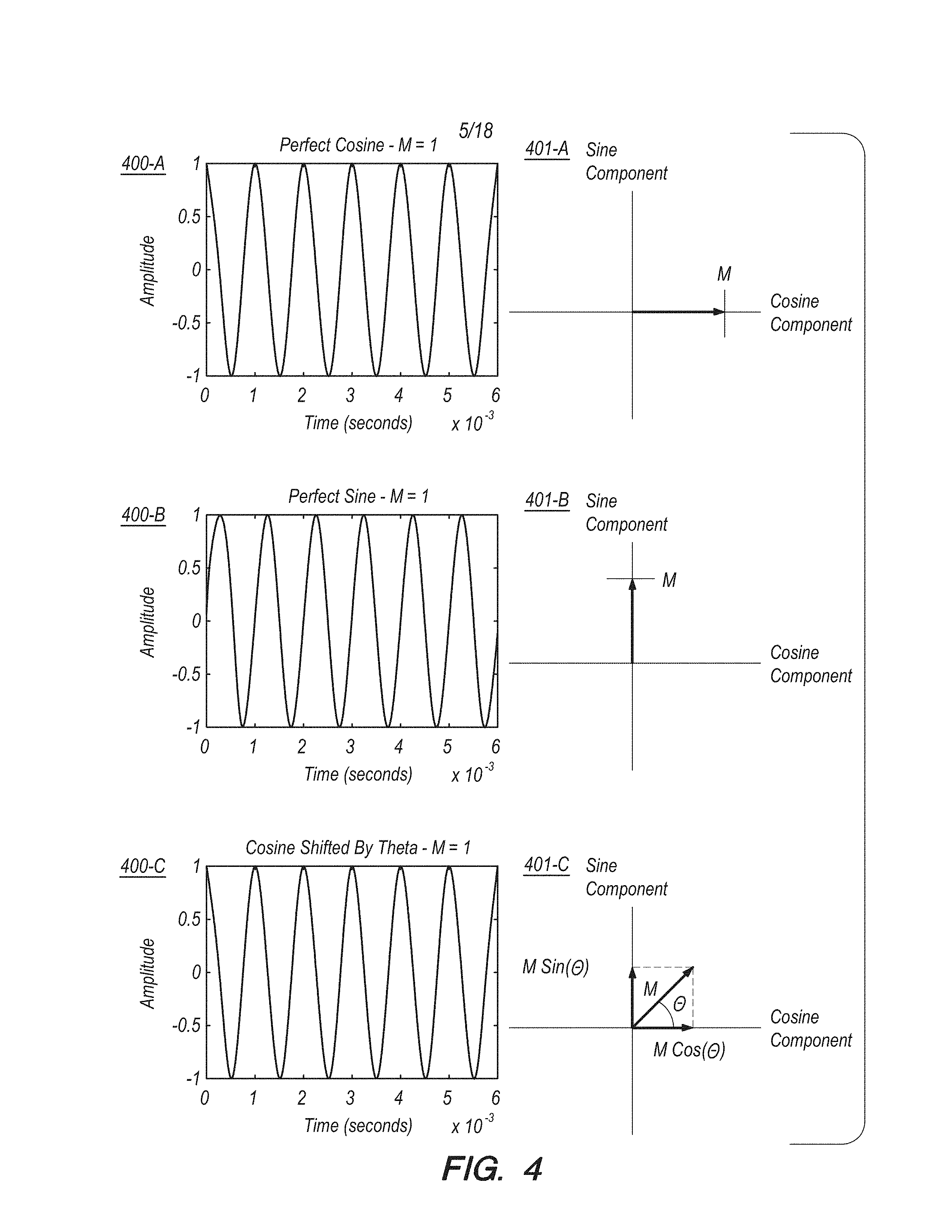
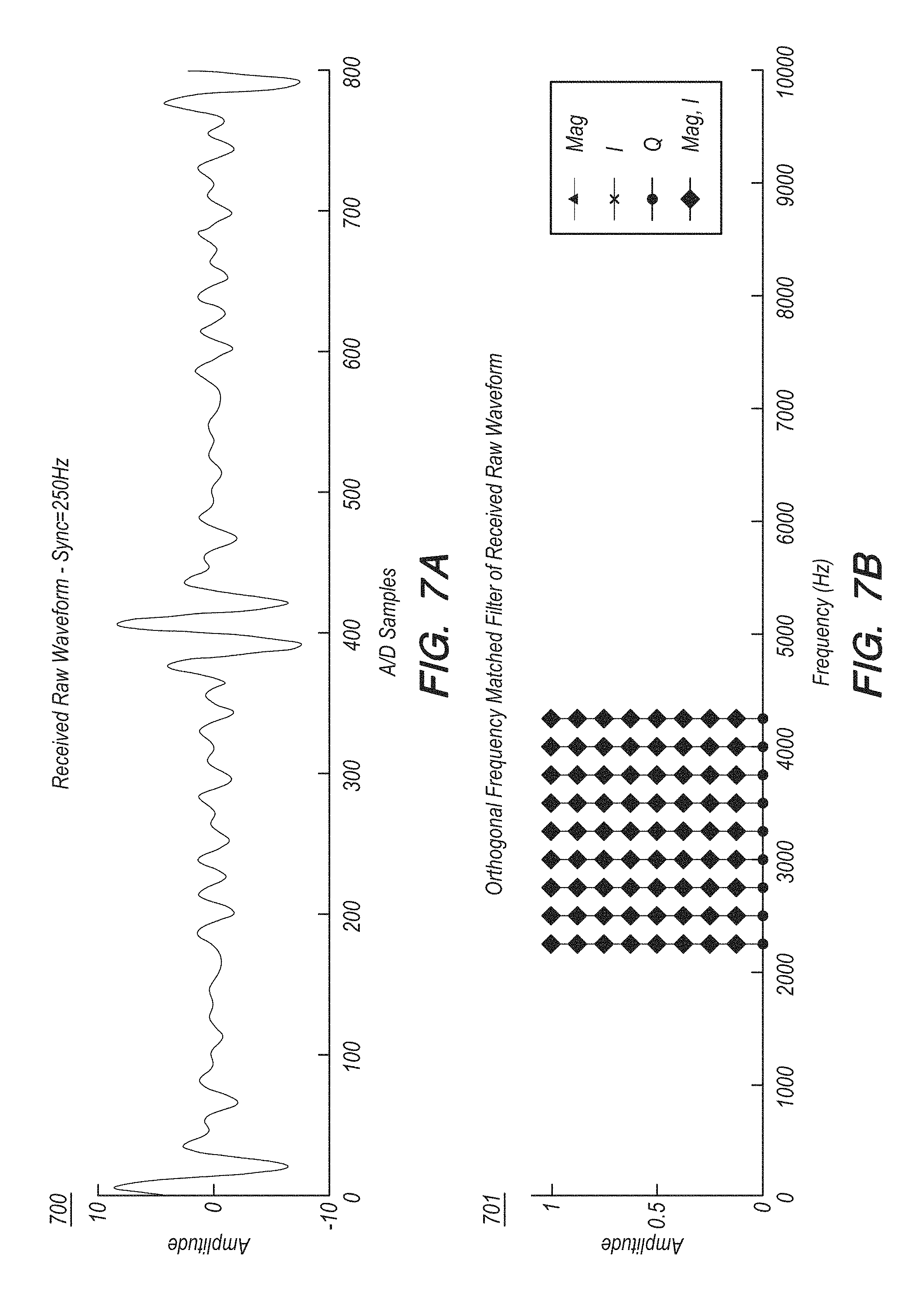
Electromagnetic navigation (EMN) has helped expand medical imaging, diagnosis, prognosis, and treatment capabilities by enabling a location and/or an orientation of a medical device to be accurately determined while the device is within the body of a patient. One example of a medical procedure in which EMN is employed is ELECTROMAGNETIC NAVIGATION BRONCHOSCOPY.RTM. (ENB.TM.), which includes a planning phase and a navigation phase. During the planning phase, a computed tomography (CT) scan of the chest of the patient is used to generate a virtual three-dimensional bronchial map of the patient and a planned pathway for the navigation phase. During the navigation phase, a field generating antenna assembly radiates an electromagnetic signal (for example, including one or more cosine waves) throughout a sensing volume within which the chest of the patient is positioned. A practitioner inserts into the airway of the patient an electromagnetic sensor that senses the radiated electromagnetic signal. A computing device captures a sample of the electromagnetic signal during a sampling window, and determines a location and/or an orientation (e.g., relative to the planned pathway) of the electromagnetic sensor based on characteristics (e.g., amplitude and/or phase) of the sampled electromagnetic signal and based on a previously generated mapping of electromagnetic signal measurements at respective sensor locations in the sensing volume.
In some cases--for instance, because of various sensor or antenna inductances, signal chain delays (e.g., analog or digital), and/or any delay from when the synchronization pulse occurs to when the acquisition or electromagnetic field generation actually begins--the sampled electromagnetic signal captured during the sampling window may not include a perfect cosine (or sine) waveform. Also, because of variations in the output current level(s) of transmitter channel(s) and/or in the gain(s) of receiver channel circuitry, the amplitude of the sampled electromagnetic signal captured at a particular location and orientation within the sensing volume relative to the field generating antenna assembly may vary from system to system. Additionally, because generating the mapping of electromagnetic signal measurements at respective sensor locations in the sensing volume can be laborious and time consuming, it may be desirable to reuse in multiple other systems a mapping that was previously generated based on an initial system. In order to do so, however, the initial system and the multiple other systems may require calibration to some common baseline.
Given the foregoing, a need exists for systems and methods for calibrating and/or optimizing an electromagnetic navigation system.
SUMMARY
In accordance with one aspect of the present disclosure, a method for calibrating an electromagnetic navigation system is provided. The method includes receiving, by way of a receiving antenna, a signal having a first magnitude value and a first phase value. A non-calibrated in-phase component and a non-calibrated quadrature component are computed based on the first magnitude value and the first phase value. A calibrated phase value is computed based on the non-calibrated in-phase component and the non-calibrated quadrature component. A calibrated in-phase component is computed based on the calibrated phase value, the non-calibrated in-phase component, and the non-calibrated quadrature component. A calibrated quadrature component is computed based on the calibrated phase value, the non-calibrated in-phase component, and the non-calibrated quadrature component. A calibrated magnitude value is computed based on the calibrated in-phase component. The calibrated phase value and the calibrated magnitude value are stored in a table for use during an electromagnetic navigation procedure.
In another aspect of the present disclosure, the method further includes transmitting the signal by way of a transmitting antenna, with the transmitting and receiving being synchronized to one another.
In yet another aspect of the present disclosure, the method further includes performing a lookup in a sine table and/or a cosine table based on the first magnitude value and the first phase value, with the computing of the non-calibrated in-phase component and/or the non-calibrated quadrature component being based on a result of the lookup.
In a further aspect of the present disclosure, the calibrated phase value is computed according to the equation:
.theta..times..times..times..times. ##EQU00001## where .theta..sub.cal represents the calibrated phase value, Q.sub.non-calibrated represents the non-calibrated quadrature component, and I.sub.non-calibrated represents the non-calibrated in-phase component.
In still another aspect of the present disclosure, the calibrated in-phase component is computed according to the equation: I.sub.calibrated=I.sub.non-calibrated.times.cos(.theta..sub.cal)+Q.sub.no- n-calibrated.times.sin(.theta..sub.cal), where I.sub.calibrated represents the calibrated in-phase component, I.sub.non-calibrated represents the non-calibrated in-phase component, .theta..sub.cal represents the calibrated phase value, and Q.sub.non-calibrated represents the non-calibrated quadrature component.
In another aspect of the present disclosure, the calibrated quadrature component is computed according to the equation: Q.sub.calibrated=-I.sub.non-calibrated.times.sin(.theta..sub.cal)+Q.sub.n- on-calibrated.times.cos(.theta..sub.cal) where Q.sub.calibrated represents the calibrated quadrature component, I.sub.non-calibrated represents the non-calibrated in-phase component, .theta..sub.cal represents the calibrated phase value, and Q.sub.non-calibrated represents the non-calibrated quadrature component.
In yet another aspect of the present disclosure, the calibrated magnitude value is computed according to the equation:
##EQU00002## where M.sub.cal represents the calibrated magnitude value and I.sub.calibrated represents the calibrated in-phase component.
In a further aspect of the present disclosure, the method further includes determining whether the calibrated magnitude value is less than zero. In response to a determination that the calibrated magnitude value is less than zero, a second calibrated phase value is computed, and the calibrated magnitude value, the calibrated in-phase component, and the calibrated quadrature component are recomputed based on the second calibrated phase value.
In still another aspect of the present disclosure, the method further includes determining whether the calibrated magnitude value is less than zero and whether the calibrated phase value is less than or equal to zero. In response to a determination that the calibrated magnitude value is less than zero and the calibrated phase value is less than or equal to zero, a second calibrated phase value is computed according to the equation: .theta..sub.cal'=.theta..sub.cal+.pi., where .theta..sub.cal represents the second calibrated phase value and .theta..sub.cal represents the calibrated phase value. The calibrated magnitude value, the calibrated in-phase component, and the calibrated quadrature component are recomputed based on the second calibrated phase value.
In another aspect of the present disclosure, the method further includes determining whether the calibrated magnitude value is less than zero and whether the calibrated phase value is greater than zero. In response to a determination that the calibrated magnitude value is less than zero and the calibrated phase value is greater than zero, a second calibrated phase value is computed according to the equation: .theta..sub.cal'=.theta..sub.cal-.pi., where .theta..sub.cal' represents the second calibrated phase value and .theta..sub.cal represents the calibrated phase value. The calibrated magnitude value, the calibrated in-phase component, and the calibrated quadrature component are recomputed based on the second calibrated phase value.
In yet another aspect of the present disclosure, the method further includes, during the electromagnetic navigation procedure, receiving a second signal having a second magnitude value and a second phase value; computing a second non-calibrated in-phase component and a second non-calibrated quadrature component based on the second magnitude value and the second phase value; and computing a corrected in-phase component and a corrected quadrature component based on the calibrated phase value, the calibrated magnitude value, the second non-calibrated in-phase component, and the second non-calibrated quadrature component.
In a further aspect of the present disclosure, the corrected in-phase component is computed according to the equation: I.sub.c=M.sub.cal.times.((I.sub.non-cal2).times.cos(.theta..sub.cal)+(Q.s- ub.non-cal2).times.sin(.theta..sub.cal)), and the corrected quadrature component is computed according to the equation: Q.sub.c=M.sub.cal.times.(-(I.sub.non-cal2).times.sin(.theta..sub.cal)+(Q.- sub.non-cal2).times.cos(.theta..sub.cal)), where I.sub.c represents the corrected in-phase component, M.sub.cal represents the calibrated magnitude value, I.sub.non-cal2 represents the second non-calibrated in-phase component, .theta..sub.cal represents the calibrated phase value, Q.sub.non-cal2 represents the second non-calibrated quadrature component, and Q.sub.c represents the corrected quadrature component.
In accordance with another aspect of the present disclosure, a system for calibrating an electromagnetic navigation system is provided. The system includes a processor and a memory. The memory includes instructions that, when executed by the processor, cause the processor to receive, by way of a receiving antenna, a signal having a first magnitude value and a first phase value. A non-calibrated in-phase component and a non-calibrated quadrature component are computed based on the first magnitude value and the first phase value. A calibrated phase value is computed based on the non-calibrated in-phase component and the non-calibrated quadrature component. A calibrated in-phase component is computed based on the calibrated phase value, the non-calibrated in-phase component, and the non-calibrated quadrature component. A calibrated quadrature component is computed based on the calibrated phase value, the non-calibrated in-phase component, and the non-calibrated quadrature component. A calibrated magnitude value is computed based on the calibrated in-phase component. The calibrated phase value and the calibrated magnitude value are stored, in a table in the memory, for use during an electromagnetic navigation procedure.
In another aspect of the present disclosure, the memory further stores instructions that, when executed by the processor, cause the processor to compute the calibrated phase value according to the equation:
.theta..times..times..times..times. ##EQU00003## where .theta..sub.cal represents the calibrated phase value, Q.sub.non-calibrated represents the non-calibrated quadrature component, and I.sub.non-calibrated represents the non-calibrated in-phase component.
In a further aspect of the present disclosure, the memory further stores instructions that, when executed by the processor, cause the processor to compute the calibrated in-phase component according to the equation: I.sub.calibrated=I.sub.non-calibrated.times.cos(.theta..sub.cal)+Q.sub.no- n-calibrated.times.sin(.theta..sub.cal), where I.sub.calibrated represents the calibrated in-phase component, I.sub.non-calibrated represents the non-calibrated in-phase component, .theta..sub.cal represents the calibrated phase value, and Q.sub.non-calibrated represents the non-calibrated quadrature component.
In yet another aspect of the present disclosure, the memory further stores instructions that, when executed by the processor, cause the processor to compute the calibrated quadrature component according to the equation: Q.sub.calibrated=-I.sub.non-calibrated.times.sin(.theta..sub.ca- l)+Q.sub.non-calibrated.times.cos(.theta..sub.cal), where Q.sub.calibrated represents the calibrated quadrature component, I.sub.non-calibrated represents the non-calibrated in-phase component, .theta..sub.cal represents the calibrated phase value, and Q.sub.non-calibrated represents the non-calibrated quadrature component.
In another aspect of the present disclosure, the memory further stores instructions that, when executed by the processor, cause the processor to compute the calibrated magnitude value according to the equation:
##EQU00004## where M.sub.cal represents the calibrated magnitude value and I.sub.calibrated represents the calibrated in-phase component.
In a further aspect of the present disclosure, the memory also stores instructions that, when executed by the processor, cause the processor to determine whether the calibrated magnitude value is less than zero. In response to a determination that the calibrated magnitude value is less than zero the processor executes the instructions to compute a second calibrated phase value, and recompute the calibrated magnitude value, the calibrated in-phase component, and the calibrated quadrature component based on the second calibrated phase value.
In yet another aspect of the present disclosure, the memory further stores instructions that, when executed by the processor, cause the processor to, during the electromagnetic navigation procedure, (1) receive a second signal having a second magnitude value and a second phase value; (2) compute a second non-calibrated in-phase component and a second non-calibrated quadrature component based on the second magnitude value and the second phase value; and (3) compute a corrected in-phase component and a corrected quadrature component based on the calibrated phase value, the calibrated magnitude value, the second non-calibrated in-phase component, and the second non-calibrated quadrature component.
In accordance with another aspect of the present disclosure, a non-transitory computer-readable medium is provided. The computer-readable medium stores sequences of instructions that, when executed by a processor, cause the processor to perform a method for calibrating an electromagnetic navigation system. The method includes receiving, by way of a receiving antenna, a signal having a first magnitude value and a first phase value. A non-calibrated in-phase component and a non-calibrated quadrature component are computed based on the first magnitude value and the first phase value. A calibrated phase value is computed based on the non-calibrated in-phase component and the non-calibrated quadrature component. A calibrated in-phase component is computed based on the calibrated phase value, the non-calibrated in-phase component, and the non-calibrated quadrature component, and a calibrated quadrature component is computed based on the calibrated phase value, the non-calibrated in-phase component, and the non-calibrated quadrature component. A calibrated magnitude value is computed based on the calibrated in-phase component. The calibrated phase value and the calibrated magnitude value are stored in a table for use during an electromagnetic navigation procedure.
In accordance with another aspect of the present disclosure, a system including an antenna assembly for calibrating an electromagnetic navigation system is provided. The antenna assembly includes a substrate, multiple pairs of transmit coils, multiple receive coils, multiple input terminals, and multiple output terminals. The substrate includes multiple layers, with each of the transmit coils being deposited on a respective one of the layers, and each of the receive coils being deposited on another respective one of the layers. Each of the pairs of transmit coils corresponds to a respective one of the receive coils. Each of the input terminals is coupled to a respective one of the pairs of transmit coils, and each of the output terminals is coupled to a respective one of the receive coils.
In another aspect of the present disclosure, each of the receive coils of the system is arranged on a respective one of the layers that is located in between a pair of the layers on which the corresponding pair of transmit coils are respectively deposited.
In further aspects of the present disclosure, each of the pairs of transmit coils of the system forms a Helmholtz pair and/or the antenna assembly of the system is an impedance-controlled antenna assembly.
In yet another aspect of the present disclosure, the system further includes a computing device including a processor and a memory. The processor is coupled to the pairs of transmit coils by way of the input terminals, respectively, and is coupled to the receive coils by way of the output terminals, respectively. The memory includes instructions that, when executed by the processor, cause the processor to transmit, by way of at least one of the pairs of transmit coils, a signal having a first magnitude value and a first phase value. The signal is received by way of at least one of the receive coils. A non-calibrated in-phase component and a non-calibrated quadrature component are computed based on the first magnitude value and the first phase value. A calibrated phase value is computed based on the non-calibrated in-phase component and the non-calibrated quadrature component. A calibrated in-phase component is computed based on the calibrated phase value, the non-calibrated in-phase component, and the non-calibrated quadrature component. A calibrated quadrature component is computed based on the calibrated phase value, the non-calibrated in-phase component, and the non-calibrated quadrature component. A calibrated magnitude value is computed based on the calibrated in-phase component. The calibrated phase value and the calibrated magnitude value are stored in a table for use during an electromagnetic navigation procedure.
In another aspect of the present disclosure, the system is configured such that the transmitting of the signal by way of one or more of the pairs of transmit coils and the receiving of the signal by way of one or more of the receive coils are synchronized to one another.
In a further aspect of the present disclosure, the memory stores further instructions that, when executed by the processor, cause the processor to perform a lookup in a sine table and/or a cosine table based on the first magnitude value and the first phase value, and the computing of the non-calibrated in-phase component and/or the non-calibrated quadrature component is further based on a result of the lookup.
In yet another aspect of the present disclosure, the memory stores further instructions that, when executed by the processor, cause the processor to compute the calibrated phase value according to the equation:
.theta..times..times..times..times. ##EQU00005## where .theta..sub.cal represents the calibrated phase value, Q.sub.non-calibrated represents the non-calibrated quadrature component, and I.sub.non-calibrated represents the non-calibrated in-phase component.
In another aspect of the present disclosure, the memory stores further instructions that, when executed by the processor, cause the processor to compute the calibrated in-phase component according to the equation: I.sub.calibrated=I.sub.non-calibrated.times.cos(.theta..sub.cal)+Q.sub.no- n-calibrated.times.sin(.theta..sub.cal), where I.sub.calibrated represents the calibrated in-phase component, I.sub.non-calibrated represents the non-calibrated in-phase component, .theta..sub.cal represents the calibrated phase value, and Q.sub.non-calibrated represents the non-calibrated quadrature component.
In a further aspect of the present disclosure, the memory further stores instructions that, when executed by the processor, cause the processor to compute the calibrated quadrature component according to the equation: Q.sub.calibrated=-I.sub.non-calibrated.times.sin(.theta..sub.cal)+Q.sub.n- on-calibrated.times.cos(.theta..sub.cal), where Q.sub.calibrated represents the calibrated quadrature component, I.sub.non-calibrated represents the non-calibrated in-phase component, .theta..sub.cal represents the calibrated phase value, and Q.sub.non-calibrated represents the non-calibrated quadrature component.
In yet another aspect of the present disclosure, the memory further stores instructions that, when executed by the processor, cause the processor to compute the calibrated magnitude value according to the equation:
##EQU00006## where M.sub.cal represents the calibrated magnitude value and I.sub.calibrated represents the calibrated in-phase component.
In another aspect of the present disclosure, the memory further stores instructions that, when executed by the processor, cause the processor to determine whether the calibrated magnitude value is less than zero, and, in response to a determination that the calibrated magnitude value is less than zero: (1) compute a second calibrated phase value, and (2) recompute the calibrated magnitude value, the calibrated in-phase component, and the calibrated quadrature component based on the second calibrated phase value.
In still a further aspect of the present disclosure, the memory stores further instructions that, when executed by the processor, cause the processor to determine whether the calibrated magnitude value is less than zero and whether the calibrated phase value is less than or equal to zero; and, in response to a determination that the calibrated magnitude value is less than zero and the calibrated phase value is less than or equal to zero: (1) compute a second calibrated phase value according to the equation: .theta..sub.cal'=.theta..sub.cal+.pi., where .theta..sub.cal represents the second calibrated phase value and .theta..sub.cal represents the calibrated phase value; and (2) recompute the calibrated magnitude value, the calibrated in-phase component, and the calibrated quadrature component based on the second calibrated phase value.
In another aspect of the present disclosure, the memory further stores instructions that, when executed by the processor, cause the processor to determine whether the calibrated magnitude value is less than zero and whether the calibrated phase value is greater than zero; and, in response to a determination that the calibrated magnitude value is less than zero and the calibrated phase value is greater than zero: (1) compute a second calibrated phase value according to the equation: .theta..sub.cal'=.theta..sub.cal-.pi., where .theta..sub.cal represents the second calibrated phase value and .theta..sub.cal represents the calibrated phase value; and (2) recompute the calibrated magnitude value, the calibrated in-phase component, and the calibrated quadrature component based on the second calibrated phase value.
In yet another aspect of the present disclosure, the memory further stores instructions that, when executed by the processor, cause the processor to: (1) receive a second signal having a second magnitude value and a second phase value; (2) compute a second non-calibrated in-phase component and a second non-calibrated quadrature component based on the second magnitude value and the second phase value; and (3) compute a corrected in-phase component and a corrected quadrature component based on the calibrated phase value, the calibrated magnitude value, the second non-calibrated in-phase component, and the second non-calibrated quadrature component.
In a further aspect of the present disclosure, the memory further stores instructions that, when executed by the processor, cause the processor to compute the corrected in-phase component according to the equation: I.sub.c=M.sub.cal.times.((I.sub.non-cal2).times.cos(.theta..sub.cal)+(Q.s- ub.non-cal2).times.sin(.theta..sub.cal)), where I.sub.c represents the corrected in-phase component, M.sub.cal represents the calibrated magnitude value, I.sub.non-cal2 represents the second non-calibrated in-phase component, .theta..sub.cal represents the calibrated phase value, and Q.sub.non-cal2 represents the second non-calibrated quadrature component.
In another aspect of the present disclosure, the memory stores further instructions that, when executed by the processor, cause the processor to compute the corrected quadrature component according to the equation: Q.sub.c=M.sub.cal.times.(-(I.sub.non-cal2).times.sin(.theta..sub.cal)+(Q.- sub.non-cal2).times.cos(.theta..sub.cal)), where Q.sub.c represents the corrected quadrature component, M.sub.cal represents the calibrated magnitude value, I.sub.non-cal2 represents the second non-calibrated in-phase component, .theta..sub.cal represents the calibrated phase value, and Q.sub.non-cal2 represents the second non-calibrated quadrature component.
In accordance with another aspect of the present disclosure, a system including an antenna assembly for calibrating an electromagnetic navigation system is provided. The antenna assembly includes a substrate, multiple pairs of transmit coils, multiple pairs of receive coils, multiple input terminals, and multiple output terminals. The substrate includes multiple layers, with each of the transmit coils being deposited on a respective one of the layers and each of the receive coils being deposited on another respective one of the layers. Each of the pairs of transmit coils corresponds to a respective pair of receive coils. The multiple input terminals are coupled to the multiple pairs of transmit coils, respectively, and the multiple output terminals are coupled to the multiple pairs of receive coils, respectively.
In another aspect of the present disclosure, the system further includes a computing device having a processor and a memory. The processor is coupled to the pairs of transmit coils by way of the input terminals, respectively, and is also coupled to the pairs of receive coils by way of the output terminals, respectively. The memory includes instructions that, when executed by the processor, cause the processor to: (1) transmit, by way of at least one of the pairs of transmit coils, a signal having a first magnitude value and a first phase value; (2) receive the signal by way of at least one of the pairs of receive coils; (3) compute a non-calibrated in-phase component and a non-calibrated quadrature component based on the first magnitude value and the first phase value; (4) compute a calibrated phase value based on the non-calibrated in-phase component and the non-calibrated quadrature component; (5) compute a calibrated in-phase component based on the calibrated phase value, the non-calibrated in-phase component, and the non-calibrated quadrature component; (6) compute a calibrated quadrature component based on the calibrated phase value, the non-calibrated in-phase component, and the non-calibrated quadrature component; (7) compute a calibrated magnitude value based on the calibrated in-phase component; and (8) store the calibrated phase value and the calibrated magnitude value in a table for use during an electromagnetic navigation procedure.
In yet another aspect of the present disclosure, each of the pairs of receive coils includes a first receive coil, deposited on a first layer of the plurality of layers, and a second receive coil, deposited on a second layer of the plurality of layers, with the first layer and the second layer each being located between a pair of the layers on which the corresponding pair of transmit coils are respectively deposited.
In accordance with yet a further aspect of the present disclosure, a method for optimizing an electromagnetic navigation system is provided. The method includes generating multiple test signals corresponding to multiple combinations of phase offset values of multiple frequency components, respectively. Based on the test signals, a table is generated, the table including multiple peak signal amplitudes associated with the multiple test signals, respectively. A minimum value of the stored peak signal amplitudes is identified in the table. Based on the table, a determination is made as to which one of the combinations of phase offset values is associated with the minimum value of the stored peak signal amplitudes. The determined combination of phase offset values is stored in a memory for use, during an electromagnetic navigation procedure, in generating a signal including the frequency components having the determined combination of phase offset values, respectively.
In another aspect of the present disclosure, as part of the method, the generating the multiple test signals includes, for each of the combinations of phase offset values, respectively: (1) generating a test signal including the frequency components having the respective combination of phase offset values, respectively; and (2) transmitting the test signal by way of a transmitting antenna.
In a further aspect of the present disclosure, the method further includes, for each of the combinations of phase offset values, respectively: (1) receiving the test signal by way of a receiving antenna; (2) capturing, during a sampling window, a sample of the received test signal; (3) measuring a peak signal amplitude of the captured sample; and (4) storing, in the table, the peak signal amplitude in association with the respective combination of phase offset values.
In yet another aspect of the present disclosure, as part of the method, the generating the test signal, the transmitting the test signal, and/or the receiving the test signal is performed by way of computer-implemented simulation.
In still another aspect of the present disclosure, each of the combinations of phase offset values employed in the method includes multiple phase offset values that correspond to the multiple frequency components, respectively.
In another aspect of the present disclosure, the method further includes generating the multiple combinations of phase offset values based on the multiple frequency components and a phase offset step size. Each of the combinations of phase offset values includes a respective set of phase offset values that correspond to the set of frequency components, respectively, and each of the phase offset values has a value in a range from zero to a maximum value, in increments of the phase offset step size.
In a further aspect of the present disclosure, the method further includes, during the electromagnetic navigation procedure: (1) generating a second signal including the multiple frequency components having the determined combination of phase offset values, respectively; (2) amplifying the second signal so as to have a magnitude greater than a magnitude of the test signal; and (3) transmitting the second signal.
In yet another aspect of the present disclosure, the method further includes, during the electromagnetic navigation procedure, (1) receiving a second signal that includes the multiple frequency components having the determined combination of phase offset values, respectively; and (2) amplifying the second signal so as to have a magnitude greater than a magnitude of the test signal.
In accordance with another aspect of the present disclosure, a system for optimizing an electromagnetic navigation system is provided. The system includes a processor and a memory. The memory stores instructions that, when executed by the processor, cause the processor to: (1) generate multiple test signals corresponding to multiple combinations of phase offset values of multiple frequency components, respectively; (2) generate, based on the multiple test signals, a table that includes a plurality of peak signal amplitudes associated with the multiple test signals, respectively; (3) identify, in the table, a minimum value of the stored peak signal amplitudes; (4) determine, based on the table, which one of the plurality of combinations of phase offset values is associated with the minimum value of the stored peak signal amplitudes; and (5) store the determined combination of phase offset values in the memory for use, during an electromagnetic navigation procedure, in generating a signal including the multiple frequency components having the determined combination of phase offset values, respectively
In another aspect of the present disclosure, the memory of the system further stores instructions that, when executed by the processor, cause the processor to generate the plurality of test signals by, for each of the combinations of phase offset values, respectively: (1) generating a test signal including the multiple frequency components having the respective combination of phase offset values; and (2) transmitting the test signal by way of a transmitting antenna.
In a further aspect of the present disclosure, the memory of the system further stores instructions that, when executed by the processor, cause the processor to, for each of the combinations of phase offset values, respectively: (1) receive the test signal by way of a receiving antenna; (2) capture a sample of the received test signal during a sampling window; (3) measure a peak signal amplitude of the captured sample; and (4) store, in the table, the peak signal amplitude in association with the respective combination of phase offset values.
In yet another aspect of the present disclosure, each of the combinations of phase offset values employed in the system includes multiple phase offset values that correspond to the multiple frequency components, respectively.
In another aspect of the present disclosure, the memory of the system further stores instructions that, when executed by the processor, cause the processor to generate the multiple combinations of phase offset values based on the multiple frequency components and a phase offset step size. In this example, each of the combinations of phase offset values includes a respective set of phase offset values corresponding to the set of frequency components, respectively, and each of the phase offset values has a value in a range from zero to a maximum value, in increments of the phase offset step size.
In a further aspect of the present disclosure, the memory further stores instructions that, when executed by the processor, cause the processor to, during the electromagnetic navigation procedure: (1) generate a second signal including the multiple frequency components having the determined combination of phase offset values, respectively; (2) amplify the second signal so as to have a magnitude greater than a magnitude of the test signal; and (3) transmit the second signal.
In yet another aspect of the present disclosure, the memory further stores instructions that, when executed by the processor, cause the processor to, during the electromagnetic navigation procedure: (1) receive a second signal that includes the multiple frequency components having the determined combination of phase offset values, respectively; and (2) amplify the second signal so as to have a magnitude greater than a magnitude of the test signal.
In accordance with another aspect of the present disclosure, a non-transitory computer-readable medium is provided. The computer-readable medium stores sequences of instructions that, when executed by a processor, cause the processor to perform a method for optimizing an electromagnetic navigation system. The method includes generating multiple test signals corresponding to multiple combinations of phase offset values of multiple frequency components, respectively. Based on the multiple test signals, a table is generated, the table including multiple peak signal amplitudes associated with the multiple test signals, respectively. A minimum value of the stored peak signal amplitudes is identified in the table. Based on the table, a determination is made as to which one of the combinations of phase offset values is associated with the minimum value of the stored peak signal amplitudes. The determined combination of phase offset values is stored in a memory for use, during an electromagnetic navigation procedure, in generating a signal including the frequency components having the determined combination of phase offset values, respectively
In another aspect of the present disclosure, the non-transitory computer-readable medium further stores sequences of instructions that cause the generating of the test signals to include, for each of the combinations of phase offset values, respectively: (1) generating a test signal including the frequency components having the respective combination of phase offset values; and (2) transmitting the test signal by way of a transmitting antenna.
In a further aspect of the present disclosure, the computer-readable medium further stores sequences of instructions that, when executed by the processor, cause the processor to, for each of the combinations of phase offset values, respectively: (1) receive the test signal by way of a receiving antenna; (2) capture a sample of the received test signal during a sampling window; (3) measure a peak signal amplitude of the captured sample; and (4) store the peak signal amplitude in the table in association with the respective combination of phase offset values.
In yet another aspect of the present disclosure, each of the combinations of phase offset values includes multiple phase offset values that correspond to the multiple frequency components, respectively.
In still a further aspect of the present disclosure, the computer readable medium further stores sequences of instructions that, when executed by the processor, cause the processor to generate the combinations of phase offset values based on the multiple frequency components and a phase offset step size. In this example, each of the combinations of phase offset values includes a respective set of phase offset values that correspond to the set of frequency components, respectively, and each of the phase offset values has a value in a range from zero to a maximum value, in increments of the phase offset step size.
Any of the above aspects and embodiments of the present disclosure may be combined without departing from the scope of the present disclosure.
BRIEF DESCRIPTION OF THE DRAWINGS
The patent or application file contains at least one drawing executed in color. Copies of this patent or patent application publication with color drawing(s) will be provided by the Office upon request and payment of the necessary fee.
Objects and features of the presently disclosed systems and methods will become apparent to those of ordinary skill in the art when descriptions of various embodiments are read with reference to the accompanying drawings, of which:
FIG. 1 shows an example electromagnetic navigation system, in accordance with the present disclosure;
FIG. 2 is a flowchart illustrating an example procedure for calibrating an electromagnetic navigation system, in accordance with the present disclosure;
FIG. 3A and FIG. 3B (collectively, FIG. 3) depict example frequency responses of in-phase and quadrature digital filters, in accordance with the present disclosure;
FIG. 4 illustrates example electromagnetic signals and the sine components and cosine components thereof, in accordance with the present disclosure;
FIG. 5A, FIG. 5B, and FIG. 5C (collectively, FIG. 5) illustrate an example frequency multiplexed electromagnetic signal, and results of applying a filter and a Fast Fourier Transform (FFT) to the signal in an example electromagnetic navigation system, in accordance with the present disclosure;
FIG. 6A, FIG. 6B, and FIG. 6C (collectively, FIG. 6) illustrate an example frequency multiplexed electromagnetic signal, and results of applying a filter and an FFT to the signal in a non-calibrated electromagnetic navigation system, in accordance with the present disclosure;
FIG. 7A, FIG. 7B, and FIG. 7C (collectively, FIG. 7) illustrate an example frequency multiplexed electromagnetic signal, and results of applying a filter and an FFT to the signal in a calibrated electromagnetic navigation system, in accordance with the present disclosure;
FIG. 8 shows a diagram of an example Helmholtz coil and corresponding example input and output voltage waveforms, in accordance with the present disclosure;
FIG. 9A, FIG. 9B, and FIG. 9C (collectively, FIG. 9) illustrate aspects of an example antenna assembly of a system for calibrating an electromagnetic navigation system, in accordance with an embodiment of the present disclosure;
FIG. 10 is a flowchart illustrating an example procedure for optimizing an electromagnetic navigation system, in accordance with the present disclosure;
FIG. 11A and FIG. 11B (collectively, FIG. 11) illustrate example electromagnetic signal waveforms before and after optimization, in accordance with the present disclosure;
FIG. 12A, FIG. 12B, and FIG. 12C (collectively, FIG. 12) illustrate an example frequency multiplexed electromagnetic signal, and results of applying a filter and an FFT to the signal in an optimized electromagnetic navigation system, in accordance with the present disclosure; and
FIG. 13 is a block diagram of an example computing device for use in various embodiments of the present disclosure.
DETAILED DESCRIPTION
The present disclosure is related to systems and methods for calibrating and/or optimizing an electromagnetic navigation system. The systems and methods herein may be employed to render electromagnetic navigation systems less susceptible to various sensor or antenna inductances, signal chain delays, and/or any delay from when the synchronization pulse occurs to when the acquisition or electromagnetic field generation actually begins, which may otherwise cause the sampled electromagnetic signal captured during the sampling window to not include a perfect cosine (or sine) waveform. The systems and methods herein also may be employed to render electromagnetic navigation systems less susceptible to variations in output current level(s) of transmitter channel(s) and/or in the gain(s) of receiver channel circuitry, which may otherwise cause the amplitude of the sampled electromagnetic signal captured at a particular location and orientation within the sensing volume relative to the field generating antenna assembly to vary from system to system.
Additionally, the systems and methods herein may be employed to calibrate an initial electromagnetic navigation system and multiple other systems to a common baseline, thereby facilitating the reuse, in the multiple other electromagnetic navigation systems, of a mapping of electromagnetic signal measurements at respective sensor locations in the sensing volume that was previously generated based on the initial electromagnetic navigation system.
FIG. 1 illustrates an example electromagnetic navigation (EMN) system 100 provided in accordance with the present disclosure. In general, the EMN system 100 is configured to identify a location and/or an orientation of a medical device being navigated toward a target location within the patient's body by using, among other things, an antenna assembly that generates one or more electromagnetic fields that are sensed by a sensor affixed to the medical device. In some cases, the EMN system 100 is further configured to augment computed tomography (CT) images, magnetic resonance imaging (MRI) images, and/or fluoroscopic images employed during navigation of the medical device through the patient's body toward a target of interest, such as a deceased portion in a luminal network of the patient's lung.
The EMN system 100 includes a catheter guide assembly 110, a bronchoscope 115, a computing device 120, a monitoring device 130, a patient platform 140 (which may be referred to as an EM board), a tracking device 160, and reference sensors 170 (three sensors of which are sometimes collectively referred to as a patient sensor triplet (PST)). The bronchoscope 115 is operatively coupled to the computing device 120 (by way of the tracking device 160) and the monitoring device 130 via respective wired connections (as shown in FIG. 1) or wireless connections (not shown in FIG. 1).
During a navigation phase of an EMN bronchoscopy procedure, the bronchoscope 115 is inserted into the oral cavity of a patient 150 and captures images of the luminal network of the lung. The catheter guide assembly 110 is inserted into the bronchoscope 115 to access the periphery of the luminal network of the lung of the patient 150. The catheter guide assembly 110 may include a catheter or extended working channel (EWC) 111 with an EM sensor 112 affixed to a portion (for example, a distal portion) of the EWC 111. A locatable guide catheter (LG) may be inserted into the EWC 111 with another EM sensor (not shown in FIG. 1) affixed to a portion (for example, a distal portion) of the LG. The EM sensor 112 affixed to the EWC 111 or the EM sensor affixed to the LG is configured to receive a signal based on an electromagnetic field radiated by the antenna assembly 145 (a field generating antenna assembly), and based upon the received signal, is used to determine a location and/or an orientation of the EWC 111 or the LG during navigation through the luminal network of the lung.
The computing device 120, such as a laptop, desktop, tablet, or other suitable computing device, includes a display 122, one or more processors 124, one or more memories 126, an AC current driver 127 for providing AC current signals to the antenna assembly 145, a network interface controller 128, and one or more input devices 129. The particular configuration of the computing device 120 illustrated in FIG. 1 is provided as an example, but other configurations of the components shown in FIG. 1 as being included in the computing device 120 are also contemplated. In particular, in some embodiments, one or more of the components (122, 124, 126, 127, 128, and/or 129) shown in FIG. 1 as being included in the computing device 120 may instead be separate from the computing device 120 and may be coupled to the computing device 120 and/or to any other component(s) of the system 100 by way of one or more respective wired or wireless path(s) to facilitate the transmission of power and/or data signals throughout the system 100. For example, although not shown in FIG. 1, the AC current driver 127 may, in some example aspects, be separate from the computing device 120 and may be coupled to the antenna assembly 145 and/or coupled to one or more components of the computing device 120, such as the processor 124 and the memory 126, by way of one or more corresponding paths.
In some aspects, the EMN system 100 may also include multiple computing devices 120, wherein the multiple computing devices 120 are employed for planning, treatment, visualization, or helping clinicians in a manner suitable for medical operations. The display 122 may be touch-sensitive and/or voice-activated, enabling the display 122 to serve as both an input device and an output device. The display 122 may display two-dimensional (2D) images or three-dimensional (3D) images, such as a 3D model of a lung, to enable a practitioner to locate and identify a portion of the lung that displays symptoms of lung diseases.
The one or more memories 126 store one or more programs and/or computer-executable instructions that, when executed by the one or more processors 124, cause the one or more processors 124 to perform various functions and/or procedures. For example, the processors 124 may calculate a location and/or an orientation of the EM sensor 112 based on the electromagnetic signal that is radiated by the antenna assembly 145 and received by the EM sensor 112. The processors 124 may also perform image-processing functions to cause the 3D model of the lung to be displayed on the display 122. The processors 124 may also generate one or more electromagnetic signals to be radiated by way of the antenna assembly 145. In some embodiments, the computing device 120 may further include a separate graphic accelerator (not shown in FIG. 1) that performs only the image-processing functions so that the one or more processors 124 may be available for other programs. The one or more memories 126 also store data, such as mapping data for EMN, image data, patients' medical record data, prescription data, and/or data regarding a history of the patient's diseases, and/or other types of data.
The mapping data may link multiple grid points, in a coordinate system of an EM volume in which a medical device (e.g., the EWC 111, the LG, treatment probe, or another surgical device) navigates, to the EM signal characteristics (for example, signal strength) that correspond to the grid points, respectively. In this manner, when the EM sensor 112 senses an EM signal having certain characteristics at a particular grid point, the one or more processors 124 may compare the sensed EM signal characteristics to the EM signal characteristics in the mapping data and determine the location and/or orientation of the EM sensor 112 within the EM volume based on a result of the comparison.
As shown in FIG. 1, the platform 140 is configured to provide a flat surface upon which the patient 150 lies during the EMN navigation procedure. The antenna assembly 145, which may also be referred to as an EM field generating device, is arranged upon the platform 140 or is included as a component of the platform 140. The antenna assembly 145 includes one or more antennas, such as planar loop antennas (not shown in FIG. 1). Example aspects of the antenna assembly 145 are described in further detail below.
With the patient 150 lying upon the platform 140, the one or more processors 124 (or another signal generator not shown in FIG. 1) generate and provide to the antenna(s) of the antenna assembly 145 by way of the AC current driver 127 one or more AC current signals that the antenna(s) convert into one or more respective EM signal(s) and radiate in a manner sufficient to surround a portion of the patient 150. In some aspects, the antenna assembly 145 includes a connector that has at least two terminals, and the trace of the antenna (not shown in FIG. 1) has two ends that are coupled to the two connector terminals, respectively, to form a signal communication path from the one or more processors 145 to the antenna.
Having described an example EMN system 100, reference will now be made to FIG. 2, which is a flowchart illustrating an example procedure 200 for calibrating an EMN system such as the EMN system 100, in accordance with the present disclosure. As described in further detail below, aspects of the procedure 200 may be implemented by utilizing the antenna assembly 145 described herein in connection with FIG. 1 and/or the example antenna assembly of a system for calibrating an electromagnetic navigation system described below in connection with FIG. 9. In one example embodiment, the procedure 200 is implemented at least in part by a processor executing instructions stored by a memory.
At S201, a signal having a first magnitude value and a first phase value is transmitted or radiated by way of a transmitting antenna. In various example embodiments, the signal may be a frequency multiplexed signal having multiple frequency components, a time multiplexed signal to share a common transmit and/or receive channel, and/or a combination of a frequency multiplexed signal and a time multiplexed signal. In one embodiment, for example without limitation, three parallel transmit and receive channels may each be employed to transmit and receive frequency multiplexed signals each having three frequency components, yielding a total of nine frequency components.
At S202, the signal transmitted at S201 is received by way of a receiving antenna. In one example embodiment, although not expressly shown in FIG. 2, the transmitting at S201 and the receiving at S202 are synchronized to one another to enable consistent measurements of electromagnetic signals from one sampling window to another.
At S203 the signal received at S202 is amplified, for example by way of one or more receive channel amplifiers, and at S204 the amplified signal is digitized by way of an analog-to-digital converter (ADC).
At S205, the signal digitized at S204 is filtered, for example by way of a digital filter. Example frequency responses of in-phase and quadrature digital filters are shown in FIG. 3A and FIG. 3B, respectively (collectively, FIG. 3). In particular, FIG. 3 shows example frequency responses of in-phase digital filters (FIG. 3A) and quadrature digital filters (FIG. 3B) configured as bandpass filters tuned to pass nine frequency channels of a frequency division multiplexed signal and to reject all other frequency signals. For clarity, the frequency responses of the bandpass filters are illustrated in FIG. 3A and FIG. 3B by way of lines having different colors, respectively. The number of frequency channels illustrated in FIG. 3 is provided by way of example and not limitation. Other numbers of frequency channels are contemplated within the scope of the present disclosure.
At S206, a magnitude and phase of the signal filtered at S205 are determined according to known techniques, such as by detecting a peak amplitude of the filtered signal and/or by measuring a phase of the filtered signal relative to a time of transmission of the signal or another temporal reference point.
At S207, a non-calibrated in-phase (I) component and a non-calibrated quadrature (Q) component of the signal are computed based on the magnitude value and the phase value determined at S206. FIG. 4 illustrates example electromagnetic signals and the in-phase components (e.g., cosine or signal component) and quadrature components (e.g., sine or noise components) thereof, in accordance with an aspect of the present disclosure. In particular, 400-A depicts an example sampled electromagnetic signal that includes a cosine waveform having a magnitude M and a phase offset of zero. 401-A is a graph illustrating that the in-phase component and quadrature component computed based on the waveform of 400-A have magnitudes of M and zero, respectively. 400-B depicts an example sampled electromagnetic signal that includes a sine waveform having a magnitude M and a phase offset of zero. 401-B is a graph illustrating that the in-phase component and quadrature component computed based on the waveform of 400-B have magnitudes of zero and M, respectively. 400-C depicts an example sampled electromagnetic signal that includes a cosine waveform having a magnitude M and having a phase offset of .theta.. 401-C is a graph illustrating that the in-phase component and quadrature component computed based on the waveform of 400-C have magnitudes of M cos(.theta.) and M sin(.theta.), respectively.
In one example, the non-calibrated in-phase component is computed by performing a lookup in cosine table based on the magnitude value and the phase value determined at S206. For example, the cosine table may indicate a cosine component (or a non-calibrated in-phase component) for each combination of a magnitude and a phase value. Similarly, the non-calibrated quadrature component, in one example, is computed by performing a lookup in sine table based on the magnitude value and the phase value determined at S206. For example, the sine table may indicate a sine component (or a non-calibrated quadrature component) for each combination of a magnitude and a phase value.
At S208, a calibrated phase value is computed based on the non-calibrated in-phase component and the non-calibrated quadrature component computed at S207. In one example, the calibrated phase value is computed according to the equation:
.theta..times..times..times..times. ##EQU00007## where .theta..sub.cal represents the calibrated phase value, and Q.sub.non-calibrated and I.sub.non-calibrated represent the non-calibrated quadrature component and the non-calibrated in-phase component, respectively, computed at S207.
At S209, a calibrated in-phase component is computed based on the calibrated phase value computed at S208 and the non-calibrated in-phase component and the non-calibrated quadrature component computed at S207. In one example, the calibrated in-phase component is computed according to the equation: I.sub.calibrated=I.sub.non-calibrated.times.cos(.theta..sub.cal)+Q.sub.no- n-calibrated.times.sin(.theta..sub.cal) (2) where I.sub.calibrated represents the calibrated in-phase component, .theta..sub.cal represents the calibrated phase value computed at S208, and I.sub.non-calibrated and Q.sub.non-calibrated represent the non-calibrated in-phase component the non-calibrated quadrature component computed at S207.
At S210, a calibrated quadrature component is computed based on the calibrated phase value computed at S208 and the non-calibrated in-phase component and non-calibrated quadrature component computed at S207. In one example, the calibrated quadrature component is computed according to the equation: Q.sub.calibrated=-I.sub.non-calibrated.times.sin(.theta..sub.cal)+Q.sub.n- on-calibrated.times.cos(.theta..sub.cal) (3) where Q.sub.calibrated represents the calibrated quadrature component, .theta..sub.cal represents the calibrated phase value computed at S208, and I.sub.non-calibrated and Q.sub.non-calibrated represent the non-calibrated in-phase component and the non-calibrated quadrature component, respectively, computed at S207.
At S211, a calibrated magnitude value is computed based on the calibrated in-phase component computed at S209. In one example the calibrated magnitude value is computed according to the equation:
##EQU00008## where M.sub.cal represents the calibrated magnitude value and I.sub.calibrated represents the calibrated in-phase component computed at S209.
In some example embodiments, a determination is made as to whether the calibrated magnitude value computed at S211 is less than zero, and, in response to a determination that the calibrated magnitude value is less than zero a second calibrated phase value is computed, and the calibrated magnitude value, the calibrated in-phase component, and the calibrated quadrature component are recomputed based on the second calibrated phase value.
For instance, at S212, a determination is made as to whether the calibrated magnitude value computed at S211 is less than zero and whether the calibrated phase value computed at S208 is less than or equal to zero. If it is determined at S212 that the calibrated magnitude value is less than zero and the calibrated phase value is less than or equal to zero, then at S213 a second calibrated phase value is computed according to the equation: .theta..sub.cal'=.theta..sub.cal+.pi. (5) where .theta..sub.cal' represents the second calibrated phase value, and .theta..sub.cal represents the calibrated phase value computed at S208. For convenience, the phase values and equations herein are described in terms of radians, although one of skill in the art would appreciate how to describe the phase values and equations herein in terms of degrees instead of radians. The procedures of S207 through S211 are then repeated (for example, the calibrated in-phase component, and the calibrated quadrature component are recomputed) based on the second calibrated phase value computed at S213.
At S214, a determination is made as to whether the calibrated magnitude value computed at S211 is less than zero and whether the calibrated phase value computed at S208 is greater than zero. If it is determined at S214 that the calibrated magnitude value is less than zero and the calibrated phase value is greater than zero, then at S215 a second calibrated phase value is computed according to the equation: .theta..sub.cal'=.theta..sub.cal-.pi. (6) where .theta..sub.cal represents the second calibrated phase value and .theta..sub.cal represents the calibrated phase value. The procedures of S207 through S212 are then repeated (for example, the calibrated magnitude value, the calibrated in-phase component, and the calibrated quadrature component are recomputed) based on the second calibrated phase value computed at S215.
At S216, the calibrated phase value computed at S208 and the calibrated magnitude value computed at S211 are stored in association with one another in a table (for example, in a memory) for use during an electromagnetic navigation procedure. Table 1 below illustrates an example of a table that may be populated with calibrated phase values and calibrated magnitude values computed at S208 and S211, respectively, and stored at S216, for an example system having 9 frequencies or channels.
TABLE-US-00001 TABLE 1 .theta..sub.cal Frequency/Channel Index M.sub.cal (radians or degrees) 1 M.sub.cal1 .theta..sub.cal1 2 M.sub.cal2 .theta..sub.cal2 3 M.sub.cal3 .theta..sub.cal3 4 M.sub.cal4 .theta..sub.cal4 5 M.sub.cal5 .theta..sub.cal5 6 M.sub.cal6 .theta..sub.cal6 7 M.sub.cal7 .theta..sub.cal7 8 M.sub.cal8 .theta..sub.cal8 9 M.sub.cal9 .theta..sub.cal9
At S217, a determination is made as to whether steps of the calibration procedure 200 are to be repeated for an additional frequency (for instance, another frequency component of a frequency division multiplexed signal) and/or an additional channel (for instance, an additional parallel channel of a multiple channel antenna assembly system). If it is determined at S217 that steps of the calibration procedure 200 are to be repeated for an additional frequency and/or channel, then at S218 a frequency index and/or a channel index is incremented, and the procedures of S201 through S217 are repeated for an additional frequency and/or channel.
At S219, the calibrated phase value and the calibrated magnitude value stored at S216 are utilized in an electromagnetic navigation procedure. For instance, in one example, during the electromagnetic navigation procedure, a second signal having a second magnitude value and a second phase value is generated, transmitted and received in the manner described above in connection with S201 and S202. A second non-calibrated in-phase component and a second non-calibrated quadrature component are computed based on the second magnitude value and the second phase value. A corrected in-phase component and a corrected quadrature component are then computed based on the computed calibrated phase value, calibrated magnitude value, second non-calibrated in-phase component, and second non-calibrated quadrature component. In one example, the corrected in-phase component is computed according to the equation: I.sub.c=M.sub.cal.times.((I.sub.non-cal2).times.cos(.theta..sub.cal)+(Q.s- ub.non-cal2).times.sin(.theta..sub.cal)) (7) and the corrected quadrature component is computed according to the equation: Q.sub.c=M.sub.cal.times.(-(I.sub.non-cal2).times.sin(.theta..sub.cal)+(Q.- sub.non-cal2).times.cos(.theta..sub.cal)) (8) where I.sub.c represents the corrected in-phase component, M.sub.cal represents the calibrated magnitude value, I.sub.non-cal2 represents the second non-calibrated in-phase component, .theta..sub.cal represents the calibrated phase value, Q.sub.non-cal2 represents the second non-calibrated quadrature component, and Q.sub.c represents the corrected quadrature component.
As can be appreciated in view of the present disclosure, the calibration procedure 200 described herein can be employed to calibrate an electromagnetic navigation system, for instance, (1) to reduce the sensitivity of the electromagnetic navigation system to sources of inconsistency, such as sensor or antenna inductances, signal chain delays, and/or delays from when the synchronization pulse occurs to when the acquisition or electromagnetic field generation actually begins--that may otherwise cause a sampled electromagnetic signal captured during the sampling to not include a perfect cosine (or sine) waveform. Also, the calibration procedure 200 can also be employed to calibrate an electromagnetic navigation system to reduce its sensitivity to variations in the output current level(s) of transmitter channel(s) and/or in the gain(s) of receiver channel circuitry, which may otherwise cause the amplitude of the sampled electromagnetic signal captured at a particular location and orientation within the sensing volume relative to the field generating antenna assembly to vary from system to system. Additionally, the calibration procedure 200 may be employed to calibrate multiple electromagnetic navigation systems (for instance, being based on similar or substantially identical field generating antenna assembly 145 designs) to be calibrated to a common baseline, thereby enabling reuse in multiple electromagnetic navigation systems of a mapping that was previously generated based on an initial electromagnetic navigation system, avoiding the need to generate new mappings of electromagnetic signal measurements at respective sensor locations in the sensing volume for each electromagnetic navigation system.
Having described an example procedure 200 for calibrating an electromagnetic navigation system, reference will now be made to FIGS. 5 through 7, which illustrate an example frequency multiplexed electromagnetic signal, and results of applying a filter and an FFT to the signal in various example electromagnetic navigation systems, in accordance with aspects of the present disclosure. In particular, graph 500 of FIG. 5A shows a captured sample of an example frequency division multiplexed (FDM) electromagnetic signal that includes nine cosine functions each having a different frequency (frequency components) and each having an amplitude of 1. In addition to magnitude values, graph 501 of FIG. 5B illustrates the in-phase (I) components and quadrature (Q) components that are computed, in a model electromagnetic navigation system, based on the signal shown in graph 500 after the signal has been filtered, for example, by way of in-phase and quadrature digital filters having the example frequency responses shown in FIG. 3. Graph 502 in FIG. 5C illustrates a result of applying an FFT to the signal shown in graph 500 in the model electromagnetic navigation system. As can be seen in graph 501, each of the nine frequency components has magnitude and in-phase component values of 1 and a quadrature component value of zero.
Graph 600 of FIG. 6A and graph 700 of FIG. 7A each show a captured sample of an example frequency division multiplexed (FDM) electromagnetic signal that includes nine cosine functions that are each intended to have a different frequency (frequency components) and an amplitude of 1, but due to variations and imperfections in the system, may have variations in amplitude and phase offset. In addition to magnitude values, graph 601 of FIG. 6B illustrates the in-phase (I) components and quadrature (Q) components that are computed, in a non-calibrated electromagnetic navigation system (e.g., a system that has not been calibrated based on the calibration procedure 200), based on the signal shown in graph 600A after the signal has been filtered. Graph 602 in FIG. 6C illustrates a result of applying an FFT to the signal shown in graph 600 in the non-calibrated electromagnetic navigation system. As can be seen in graph 601, the nine frequency components each have a magnitude value of 1 but have varying in-phase and quadrature component values, due to the variations or imperfections in the captured signal.
In addition to magnitude values, graph 701 of FIG. 7B illustrates the in-phase (I) components and quadrature (Q) components that are computed, in a calibrated electromagnetic navigation system (e.g., a system that has been calibrated based on the calibration procedure 200), based on the signal shown in graph 600 after the signal has been filtered. Graph 702 in FIG. 7C illustrates a result of applying an FFT to the signal shown in graph 600 in the calibrated electromagnetic navigation system. As can be seen in graph 701, each of the nine frequency components has magnitude and in-phase component values of 1 and a quadrature component value of zero, despite the imperfections in the captured signal.
Reference will now be made to FIG. 8 and FIG. 9, which illustrate aspects of an example system for calibrating electromagnetic navigation systems, in accordance with the present disclosure. In particular, FIG. 8 shows a diagram of an example circuit 800 that includes a pair of transmitting coils 801-A and 801-B (collectively 801) (which may be, in some examples, a Helmholtz pair) coupled to an input terminal 802 (which in this example includes two conductors, but may in some embodiments include any number of conductors), a corresponding receive coil 803 coupled to an output terminal 804 (which in this example includes two conductors, but may in some embodiments include any number of conductors). Although the circuit 800 of FIG. 8 includes a single receive coil 803, this is merely provided as an example. As described in further detail below, other example embodiments are contemplated in which the circuit 800 includes multiple receive coils per receive channel, for example, multiple receive coils or receive coil pairs coupled to one another in a series circuit. The graph 805 illustrates an example input voltage signal (or waveform) that may be applied to the pair of transmit coils 801 by way of the input terminal 802, thereby causing the transmit coils 801 to radiate an electromagnetic field. In the example of graph 805, the input voltage signal is a sine waveform. The graph 806 illustrates an example output voltage signal (or waveform) that the radiated electromagnetic field may induce in the output terminal 804 by way of the receive coil 803. In the example of graph 806, the output voltage signal, which is induced based on the input sine waveform, is a cosine waveform. As described in further detail below, one or more circuits such as the circuit 800 may be included in an antenna assembly for calibrating an electromagnetic navigation system, in accordance with aspects of the present disclosure.
FIG. 9A, FIG. 9B, and FIG. 9C (collectively, FIG. 9) illustrate aspects of an example antenna assembly 903 that may be included in a system for calibrating an electromagnetic navigation system, such as the electromagnetic navigation system 100, in accordance with the present disclosure. Although not shown in FIG. 9, in some embodiments, the system for calibrating the electromagnetic navigation system includes several of the components that are described above in connection with FIG. 1, such as for example the computing device 120, the tracking module 160, the patient platform 140, and/or other components. In some embodiments, the system for calibrating an electromagnetic navigation system may employ the field generating antenna assembly 145 and the EM sensor 112 to calibrate one or more transmit and receive channel(s) of the electromagnetic navigation system 100, for instance according to the procedure 200 described herein. In other embodiments, in lieu of the field generating antenna assembly 145 and the EM sensor 112, the system for calibrating the electromagnetic navigation system includes the antenna assembly 903 of FIG. 9C, which includes one or more circuits, such as the circuit 800 of FIG. 8, each configured to be employed to calibrate a corresponding transmit and/or receive channel of the electromagnetic navigation system 100, for instance according to the procedure 200 described herein. In some examples, the computing device 120 is coupled to the antenna assembly 903 by way of transmit and receive channels thereof, and is configured to transmit and receive signals by way of the transmit and receive channels, respectively, to calibrate each transmit and receive channel.
With reference to FIG. 9C, a top view of the example antenna assembly 903 as fully fabricated is shown. In some embodiments, the antenna assembly 903 includes a substrate having multiple layers. FIG. 9A shows an exploded view 901 of the antenna assembly 903 that illustrates an example arrangement of the multiple layers of the substrate of the antenna assembly 903 (which arrangement may be referred to as a printed circuit board (PCB) stackup). The arrangement of the multiple layers of the substrate of the antenna assembly 903 that is shown in view 901 is provided as one example PCB stackup, but other PCB stackups are contemplated, for instance, with channels having single-receive-coil configurations and/or channels having multiple-receive-coil configurations, as described in further detail below.
FIG. 9B shows a plan view 902 of a single layer of the antenna assembly 903. The antenna assembly 903 includes multiple pairs of transmit coils and multiple receive coils (and/or receive coil pairs, not explicitly shown in FIG. 9), with each pair of transmit coils corresponding to a respective one of the receive coils (or receive coil pairs). In one embodiment, each set of a pair of transmit coils and a corresponding receive coil (or receive coil pair) corresponds to a particular transmit and receive channel (or a particular transmit and receive frequency) of the electromagnetic navigation system being calibrated. For instance, for an electromagnetic navigation system that includes N transmit channels and N receive channels, the antenna assembly 903 includes N pairs of transmit coils and N corresponding receive coils and/or receive coil pairs, respectively.
Although not explicitly shown in the view 901, in some example embodiments, each set of a pair of transmit coils and a corresponding receive coil of the antenna assembly 903 (for instance the pair of transmit coils 801-A.sub.1, 801-B.sub.1 and the corresponding receive coil 803.sub.1 shown in view 901) is formed as the pair of transmitting coils 801 (which may be, in some examples, a Helmholtz pair) and the corresponding receive coil 803 shown in FIG. 8. More particularly, with reference to the view 901, the pair of transmit coils 801-A.sub.1 and 801-B.sub.1 corresponds to the receive coil 803.sub.1, the pair of transmit coils 801-A.sub.N and 801-B.sub.N corresponds to the receive coil 803.sub.N, and so forth. Each pair of transmitting coils 801 is coupled, via printed circuit board pads, traces, and/or vias for example (not explicitly shown in FIG. 9), to a corresponding input terminal 802.sub.1 through 802.sub.N, respectively, and each receive coil (or, in some examples, each receive coil pair) 803.sub.1 through 803.sub.N is coupled, via printed circuit board pads, traces, and/or vias for example (not explicitly shown in FIG. 9), to a corresponding output terminal 804.sub.1 through 804.sub.N, respectively. In this way, the computing device 120 can be coupled to particular coils of the transmit coils 801 and the receive coils 803 by way of respective terminals of the input terminals 802 and the output terminals 804.
As noted above, in various example embodiments, the antenna assembly 903 may include a single receive coil per channel (which is referred to as a single-receive-coil configuration) or multiple receive coils per channel (which is referred to as a multiple-receive-coil configuration). The example arrangement of the multiple layers of the substrate of the antenna assembly 903 shown in the view 901 illustrates a single-receive-coil configuration, where each channel has a single receive coil 803.sub.1 through 803.sub.N, respectively. As indicated in the view 901, each of the transmit coils (transmit coil 801-A.sub.1 through transmit coil 801-A.sub.N and transmit coil 801-B.sub.1 through transmit coil 801-B.sub.N) is deposited on a respective one of the layers of the substrate, and each of the receive coils (receive coil 803.sub.1 through receive coil 803.sub.N) is deposited on a respective one of the layers of the substrate. In the example arrangement of view 901, each of the receive coils 803.sub.1 through 803.sub.N is arranged on a respective one of the substrate layers located in between (though not necessarily immediately adjacent to) the pair of substrate layers upon which the corresponding pair of transmit coils 801 are respectively deposited. For instance, in the single-receive-coil configuration, the receive coil 803.sub.1 is arranged on a substrate layer located in between the pair of substrate layers upon which the corresponding pair of transmit coils 801-A.sub.1 and 801-B.sub.1 are respectively deposited; and the receive coil 803.sub.N is arranged on a substrate layer that is located in between the pair of substrate layers upon which the corresponding pair of transmit coils 801-A.sub.N and 801-B.sub.N are respectively deposited.
Alternatively, although not explicitly shown in FIG. 8 or FIG. 9, in a multiple-receive-coil configuration example embodiment, each channel includes multiple (for example, a pair of) receive coils. For instance, a first channel includes a pair of series-connected receive coils arranged on a pair of substrate layers, respectively, both of which are located between the pair of substrate layers upon which the corresponding pair of transmit coils are respectively deposited, and so forth for other channels. In this example, the pair of receive coils which are deposited on different layers of the substrate, are coupled to one another in a series circuit by way of printed circuit board traces and a via that traverses the layers of the substrate, for instance. The antenna assembly 903, in some embodiments, is an impedance-controlled antenna assembly, for instance including outer layers 904 and 905 that each include traces and/or components configured to control an impedance of the antenna assembly.
As mentioned above, in various example embodiments, each receive coil 803 is implemented as a single receive coil or as a set of multiple receive coils, such as a pair of two receive coils coupled to one another in a series circuit topology. In some examples, different receive coil configurations are used to calibrate receive channels configured for different types of sensors, respectively. For instance, a receive coil configuration that includes a single receive coil (a single-receive-coil configuration) is used to calibrate a receive channel or port that, after calibration, is intended to be coupled to an EWC that includes a single coil. Alternatively, a receive coil configuration that includes multiple receive coils (a multiple-receive-coil configuration) is used to calibrate a receive channel or port that, after calibration, is intended to be coupled to a sensor, such as an LG or a PST, that includes multiple-coil assemblies, such as a pair of series-connected coils. In some example embodiments, at least one of the connectors 804 (for example, 804.sub.1) is coupled to one of the receive coils 803.sub.1 through 803.sub.N and is useable for single-receive-coil calibration, and at least another one of the connectors 804 (for example, 804.sub.N) is coupled to a set of multiple receive coils (for instance, a series-connected pair of receive coils each deposited on a respective one of the layers of the substrate, not shown in FIG. 9) and is usable for multiple-receive-coil calibration. Thus, by way of the different connectors 804.sub.1 through 804.sub.N, the antenna assembly 903 facilitates calibration of receive channels that employ different receive coil configurations.
In some example aspects, the system for calibrating the electromagnetic navigation system includes a computing device, such as the computing device 120 and/or the computing device 1300 described herein, which in turn includes a processor (for example processor 124 or 1304) and a memory (for example, memory 126 or 1302) coupled to the plurality of pairs of transmit coils 801 by way of the plurality of input terminals 802, respectively, and coupled to the plurality of receive coils 803 by way of the plurality of output terminals 804, respectively. The memory may include instructions (for example, including the data 1314 and/or the application 1316) that, when executed by the processor, cause the processor to perform the calibration procedure 200 described herein. The memory may further includes instructions that, when executed by the processor, cause the processor to synchronously transmit and receive one or more electromagnetic signal(s).
FIG. 10 is a flowchart illustrating an example procedure 1000 for optimizing an electromagnetic navigation system, in accordance with the present disclosure. In general, as described in further detail below, the procedure 1000 may be employed to determine, for a particular frequency division multiplexed signal having multiple frequency components, a combination of respective phase offsets for the frequency components (which may be referred to as an optimized combination of phase offsets) that, when the frequency components are superimposed, would yield a peak amplitude that is lower than an amplitude that would result without utilizing such phase offsets. Employing, in an electromagnetic navigation system, the phase offset combination identified by way of the procedure 1000 mitigates saturation of the ADC(s) of the system, and further enables transmit and/or receive channel gains to be increased, thereby increasing signal-to-noise ratio (SNR) and/or maximizing utilization of the dynamic range available from the ADC(s). As described below, in some example embodiments the procedure 1000 includes generating test signals and radiating or transmitting those test signals by way of an antenna, such as the antenna assembly 145 or the antenna assembly 903, and receiving and measuring samples of the transmitted test signals to determine optimal phase offsets. In other example embodiments, in lieu of radiating phase shifted waveforms using an antenna, one or more steps of the procedure 1000 are implemented by a computer (for example, by retrieving, via a processor, instructions stored in a memory and executing those instructions) to generate simulated waveforms with various phase offsets, thereby reducing the time required to determine optimal phase offsets.
Referring now to FIG. 10, at S1001, various parameters, such as for example a frequency index, a channel index, and/or other parameters, are initialized. In one example, the initialization of parameters at S1001 facilitates repetition of steps of the procedure 1000 for multiple frequencies, channels, and/or combinations of phase offset values. For instance, at S1001 a frequency index may be initialized to an initial value (e.g., 1) and a phase offset combination may be initialized to an initial value (e.g., corresponding to a phase offset combination where each phase offset equals zero).
At S1002, a frequency multiplexed electromagnetic test signal is generated, including multiple frequency components that are superimposed and that have respective phase offset values of the phase offset combination initialized at S1001. The test signal is transmitted (or radiated) by way of a transmitting antenna, such as the antenna assembly 145 or the antenna assembly 903, or is generated within a simulation environment as described above.
At S1003, the test signal radiated at S1002 is received by way of a receiving antenna, and a sample of the received test signal is captured during a sampling window. As described in further detail below, FIG. 11 illustrates example electromagnetic signal waveforms that may be captured at S1003.
At S1004, a peak signal amplitude of the captured sample is measured. At S1005, the peak signal amplitude measured at S1004 is stored in a table in association with the respective combination of phase offset values used at S1002 to generate the signal.
At S1006, a determination is made as to whether steps of the procedure 1000 are to be repeated for an additional phase offset combination for the frequency components. In one example, steps of the procedure 1000 are repeated for each possible combination of phase offset values ranging from zero to a maximum value (e.g., 2.pi. radians or 360.degree.) in increments of a phase offset step size. In such an example, the determination at S1006 of whether steps of the procedure 1000 are to be repeated is made based on whether the table populated at S1005 includes peak signal amplitude values for all possible combinations of phase offset values for the frequency components of the signal generated at S1002 given the particular phase offset step size. If the table populated at S1005 does not include peak signal amplitude values for all possible combinations of phase offset values for the frequency components of the signal generated at S1002 given the particular phase offset step size, then it is determined at S1006 that steps of the procedure 1000 are to be repeated for an additional phase offset combination ("YES" at S1006).
At S1007, the additional phase offset combination is set and the procedures of S1002 through S1006 are repeated based on the additional phase offset combination. In this manner, the table may be populated at S1005 for each possible combination of phase offset values for the frequency components, respectively, given the phase offset step size. In one example, the set of possible combinations of phase offset values is generated based on the frequency components of the signal and the phase offset step size. In particular, each of the combinations of phase offset values includes a respective set of phase offset values that correspond to the frequency components, respectively. Each of the phase offset values may have a value in a range from zero to a maximum value (e.g., 2.pi. radians or 360.degree.), in increments of the phase offset step size. For example, if the phase offset step size were 90.degree., the possible phase offset values for each frequency component would be 0.degree., 90.degree., 180.degree., and 270.degree.. In this example, the number of possible phase offset values N.sub..theta. for a particular frequency component would be 4. Thus, for a frequency multiplexed signal having a particular number of frequencies components N.sub.F, with each frequency component having a number of possible phase offset values N.sub..theta., the total number of possible combinations of phase offsets N.sub.C is computed according to the equation: N.sub.C=N.sub..theta..sup.N.sup.F (9)
If, on the other hand, the table populated at S1005 includes peak signal amplitude values for all possible combinations of phase offset values for the frequency components of the signal generated at S1002 given the particular phase offset step size, then it is determined at S1006 that steps of the procedure 1000 are not to be repeated for an additional phase offset combination ("NO at S1006").
At S1008, a minimum value among the peak signal amplitudes stored at S1005 in the completed table is identified. At S1009, based on the table, a determination is made as to which one of the plurality of combinations of phase offset values in the table is associated with the minimum value of the stored peak signal amplitudes identified at S1008.
At S1010, the combination of phase offset values determined at S1009 is stored in a table, for example in a memory, for use during an electromagnetic navigation procedure in generating an electromagnetic signal that includes the plurality of frequency components having the determined combination of phase offset values, respectively. Table 2 below illustrates an example of a table that may be populated with the combination of phase offset values .theta..sub.off for the frequency components stored at S1010, for an example system having 9 frequencies or channels.
TABLE-US-00002 TABLE 2 Frequency .theta..sub.off Frequency/Channel Index (Hz) (radians or degrees) 1 F.sub.1 .theta..sub.off1 2 F.sub.2 .theta..sub.off2 3 F.sub.3 .theta..sub.off3 4 F.sub.4 .theta..sub.off4 5 F.sub.5 .theta..sub.off5 6 F.sub.6 .theta..sub.off6 7 F.sub.7 .theta..sub.off7 8 F.sub.8 .theta..sub.off8 9 F.sub.9 .theta..sub.off9
At S1011, gain values of one or more transmit and/or receive amplifiers in the electromagnetic navigation system may be increased. during the electromagnetic navigation procedure: generating a second signal including the plurality of frequency components having the determined combination of phase offset values, respectively; amplifying the second signal so as to have a magnitude greater than a magnitude of the test signal; and transmitting the second signal. 23. The method of claim 20, further comprising: during the electromagnetic navigation procedure: receiving a second signal that includes the plurality of frequency components having the determined combination of phase offset values, respectively; and amplifying the second signal so as to have a magnitude greater than a magnitude of the test signal.
FIG. 11A and FIG. 11B (collectively, FIG. 11) illustrate example electromagnetic signal waveforms before and after optimization according to the procedure 1000, in accordance with the present disclosure. In particular, the signal waveform 1101 of FIG. 11A shows multiple separate frequency components that may be generated at S1002 without employing the combination of phase offset values determined at S1009 (for example, employing phase offset values of zero for each of the frequency components). The signal waveform 1102 of FIG. 11A represents a combination of the multiple frequency components of the waveform 1101 superimposed upon one another. The superimposed waveform 1102 has a relatively high peak amplitude that may saturate an ADC and/or make limited use of the dynamic range available from an ADC.
The signal waveform 1103 of FIG. 11B shows multiple separate frequency components that may be generated at S1002 employing the combination of phase offset values determined at S1009. The signal waveform 1104 of FIG. 11B represents a combination of the multiple frequency components of the waveform 1103 superimposed upon one another. The superimposed waveform 1104 has a peak amplitude that is lower than that of the superimposed waveform 1102, and may thus mitigate or avoid saturation of the ADC and/or make more effective use of the dynamic range available from an ADC, for example, by enabling one or more gains of the transmit and/or receive channel to be increased as described above in connection with S1011.
FIG. 12A, FIG. 12B, and FIG. 12C (collectively, FIG. 12) illustrate an example frequency multiplexed electromagnetic signal, and results of applying a filter and an FFT to the signal in an optimized electromagnetic navigation system (for instance an electromagnetic navigation system optimized according to the procedure 1000 herein), in accordance with the present disclosure. In particular, the waveform 1201 of FIG. 12A is generated using the same frequency components used to generate the waveform 600 of FIG. 6, except using the combination of phase offsets determined at S1009. Graph 1202 of FIG. 12B illustrates the in-phase (I) components and quadrature (Q) components that are computed based on the signal shown in graph 1201 after the signal has been filtered. Graph 1203 of FIG. 12C illustrates a result of applying an FFT to the signal shown in graph 1201. The in-phase (I) components and quadrature (Q) components that are computed based on the signal shown in graph 1201 after the signal has been filtered are the same as those in the graph 701 of FIG. 7, illustrating that, in one example embodiment, advantages of calibration and optimization may both be realized in a system that has been both calibrated according to the procedure 200 and optimized according to the procedure 1000.
Turning now to FIG. 13, there is shown a block diagram of a computing device 1300, which can be used as the EMN system 100, the computing device 120, the tracking device 160, and/or a computer performing any of the procedures herein, such as for example the procedures 200 and/or 1000 described herein in connection with FIG. 2 and/or FIG. 10, respectively. The computing device 1300 may include one or more of each of the following components: a memory 1302, a processor 1304, a display 1306, a network interface controller 1308, an input device 1310, and/or an output module 1312.
The memory 1302 includes any non-transitory computer-readable storage media for storing data and/or software that is executable by the processor 1304 and which controls the operation of the computing device 1300. In an embodiment, the memory 1302 may include one or more solid-state storage devices such as flash memory chips. Alternatively, or in addition to the one or more solid-state storage devices, the memory 1302 may include one or more mass storage devices connected to the processor 1304 through a mass storage controller (not shown in FIG. 13) and a communications bus (not shown in FIG. 13). Although the description of computer-readable media contained herein refers to a solid-state storage, it should be appreciated by those skilled in the art that computer-readable storage media can be any available media that can be accessed by the processor 1304. That is, computer readable storage media include non-transitory, volatile and non-volatile, removable and non-removable media implemented in any method or technology for storage of information such as computer-readable instructions, data structures, program modules or other data. For example, computer-readable storage media include RAM, ROM, EPROM, EEPROM, flash memory or other solid state memory technology, CD-ROM, DVD, Blu-Ray or other optical storage, magnetic cassettes, magnetic tape, magnetic disk storage or other magnetic storage devices, or any other medium which can be used to store the desired information and which can be accessed by the computing device 1300.
The memory 1302 may store application 1316 and/or data 1314. The application 1316 may, when executed by the processor 1304, cause the display 1306 to present user interface 1318 on the display 1306.
The processor 1304 may be a general purpose processor, a specialized graphic processing unit (GPU) configured to perform specific graphics processing tasks while freeing up the general purpose processor to perform other tasks, a programmable logic device such as a field programmable gate array (FPGA) or complex programmable logic device (CPLD), and/or any number or combination of such processors or devices configured to work independently or cooperatively.
The display 1306 may be touch-sensitive and/or voice-activated, enabling the display 1306 to serve as both an input and output device. Alternatively, a keyboard (not shown), mouse (not shown), or other data input devices may be employed.
The network interface 1308 may be configured to connect to a network, such as a local area network (LAN) including a wired network and/or a wireless network, a wide area network (WAN), a wireless mobile network, a Bluetooth network, and/or the Internet. The computing device 1300 may receive updates to its software, for example, application 1316, via the network interface controller 1308. The computing device 1300 may also display notifications on the display 1306 that a software update is available.
In another aspect, the computing device 1300 may receive computed tomographic (CT) image data of a patient from a server, for example, a hospital server, Internet server, or other similar servers, for use during surgical planning. Patient CT image data may also be provided to the computing device 1300 via a removable memory (not shown in FIG. 13).
Input device 1310 may be any device by means of which a user may interact with the computing device 1300, such as, for example, a mouse, keyboard, foot pedal, touch screen, and/or voice interface.
Output module 1312 may include any connectivity port or bus, such as, for example, parallel ports, serial ports, universal serial busses (USB), or any other similar connectivity port known to those skilled in the art.
The application 1316 may be one or more software programs stored in the memory 1302 and executed by the processor 1304 of the computing device 1300. One or more software programs in the application 1316 may be loaded from the memory 1302 and executed by the processor 1304 to perform any of the procedures herein, such as for example the procedures 200 and/or 1000 described herein in connection with FIG. 2 and/or FIG. 10, respectively.
The application 1316 may be installed directly on the computing device 1300, or may be installed on another computer, for example a central server, and opened on the computing device 1300 via the network interface 1308. Application 1316 may run natively on the computing device 1300, as a web-based application, or any other format known to those skilled in the art. In some embodiments, the application 1316 will be a single software program having all of the features and functionality described in the present disclosure. In other embodiments, the application 1316 may be two or more distinct software programs providing various parts of these features and functionality. For example, the application 1316 may include one software program for automatically designing loop antennas, another one for converting the design into a CAD file, and a third program for PCB layout software program. In such instances, the various software programs forming part of the application 1316 may be enabled to communicate with each other and/or import and export various data including settings and parameters relating to the design of the loop antennas. For example, a design of a loop antenna generated by one software program may be stored and exported to be used by a second software program to convert into a CAD file, and the converted file may be also stored and exported to be used by a PCB layout software program to complete a blueprint of the loop antenna.
The application 1316 may communicate with a user interface 1318 which generates a user interface for presenting visual interactive features to a user, for example, on the display 1306 and for receiving input, for example, via a user input device. For example, user interface 1318 may generate a graphical user interface (GUI) and output the GUI to the display 1306 for viewing by a user.
In a case where the computing device 1300 is used as the EMN system 100, the computing device 120, or the tracking device 160, the computing device 1300 may be linked to the monitoring device 130, thus enabling the computing device 1300 to control the output on the monitoring device 130 along with the output on the display 1306. The computing device 1300 may control the monitoring device 130 to display output which is the same as or similar to the output displayed on the display 1306. For example, the output on the display 1306 may be mirrored on the monitoring device 130. Alternatively, the computing device 1300 may control the monitoring device 130 to display different output from that displayed on the display 1306. For example, the monitoring device 130 may be controlled to display guidance images and information during the surgical procedure, while the display 1306 is controlled to display other output, such as configuration or status information of an electrosurgical generator (not shown in FIG. 1).
The application 1316 may include one software program for use during the planning phase, a second software program for use during the navigation or procedural phase, and/or other application(s) for other phases, such as a calibration phase, an optimization phase, and/or or the like. In such instances, the various software programs forming part of application 1316 may be enabled to communicate with each other and/or import and export various settings and parameters relating to the navigation and treatment and/or the patient to share information. For example, a treatment plan and any of its components generated by one software program during the planning phase may be stored and exported to be used by a second software program during the procedure phase.
Although embodiments have been described in detail with reference to the accompanying drawings for the purpose of illustration and description, it is to be understood that the inventive processes and apparatus are not to be construed as limited. It will be apparent to those of ordinary skill in the art that various modifications to the foregoing embodiments may be made without departing from the scope of the disclosure. For example, various steps of the procedures described herein may be implemented concurrently and/or in an order different from the example order(s) described herein.
* * * * *
D00000
D00001
D00002
D00003
D00004
D00005
D00006
D00007
D00008
D00009
D00010
D00011
D00012

D00013

D00014

D00015

D00016

D00017

D00018

M00001

M00002

M00003

M00004

M00005

M00006

M00007

M00008

XML
uspto.report is an independent third-party trademark research tool that is not affiliated, endorsed, or sponsored by the United States Patent and Trademark Office (USPTO) or any other governmental organization. The information provided by uspto.report is based on publicly available data at the time of writing and is intended for informational purposes only.
While we strive to provide accurate and up-to-date information, we do not guarantee the accuracy, completeness, reliability, or suitability of the information displayed on this site. The use of this site is at your own risk. Any reliance you place on such information is therefore strictly at your own risk.
All official trademark data, including owner information, should be verified by visiting the official USPTO website at www.uspto.gov. This site is not intended to replace professional legal advice and should not be used as a substitute for consulting with a legal professional who is knowledgeable about trademark law.