Initiating a conferencing meeting using a conference room device
Griffin , et al. Dec
U.S. patent number 10,516,707 [Application Number 15/435,892] was granted by the patent office on 2019-12-24 for initiating a conferencing meeting using a conference room device. This patent grant is currently assigned to CISCO TECHNOLOGY, INC.. The grantee listed for this patent is CISCO TECHNOLOGY, INC.. Invention is credited to Keith Griffin, Wayne Moorefield, Jr., Otto N. Williams.


| United States Patent | 10,516,707 |
| Griffin , et al. | December 24, 2019 |
Initiating a conferencing meeting using a conference room device
Abstract
The disclosed technology addresses the need in the art for a conference room device configured to aid the initiation, organization, and management of a conference meeting. A conference room device is configured to determine that a user is within a threshold distance of a conference room device and that the user is associated with a conference meeting at a current time. The conference room device is further configured to prompt the user to start the conference meeting, receive a confirmation from the user; and start the conference meeting.
| Inventors: | Griffin; Keith (Oranmore, IE), Williams; Otto N. (Berkeley, CA), Moorefield, Jr.; Wayne (San Jose, CA) | ||||||||||
|---|---|---|---|---|---|---|---|---|---|---|---|
| Applicant: |
|
||||||||||
| Assignee: | CISCO TECHNOLOGY, INC. (San
Jose, CA) |
||||||||||
| Family ID: | 62556421 | ||||||||||
| Appl. No.: | 15/435,892 | ||||||||||
| Filed: | February 17, 2017 |
Prior Publication Data
| Document Identifier | Publication Date | |
|---|---|---|
| US 20180176270 A1 | Jun 21, 2018 | |
Related U.S. Patent Documents
| Application Number | Filing Date | Patent Number | Issue Date | ||
|---|---|---|---|---|---|
| 62434805 | Dec 15, 2016 | ||||
| Current U.S. Class: | 1/1 |
| Current CPC Class: | G06Q 10/06314 (20130101); H04L 67/18 (20130101); H04L 12/1818 (20130101); G06Q 10/06311 (20130101); H04L 65/403 (20130101); G06F 3/167 (20130101); H04L 65/1069 (20130101); H04L 51/20 (20130101); H04L 67/325 (20130101); H04L 67/24 (20130101) |
| Current International Class: | H04L 12/18 (20060101); H04L 29/06 (20060101); G06Q 10/06 (20120101); H04L 29/08 (20060101); G06F 3/16 (20060101); H04L 12/58 (20060101) |
| Field of Search: | ;455/416,414.1,456.3 |
References Cited [Referenced By]
U.S. Patent Documents
| 4460807 | July 1984 | Kerr et al. |
| 4890257 | December 1989 | Anthias et al. |
| 4977605 | December 1990 | Fardeau et al. |
| 5293430 | March 1994 | Shiau et al. |
| 5694563 | December 1997 | Belfiore et al. |
| 5699082 | December 1997 | Marks et al. |
| 5745711 | April 1998 | Kitahara et al. |
| 5767897 | June 1998 | Howell |
| 5825858 | October 1998 | Shaffer et al. |
| 5874962 | February 1999 | de Judicibus et al. |
| 5889671 | March 1999 | Autermann et al. |
| 5917537 | June 1999 | Lightfoot et al. |
| 5995096 | November 1999 | Kitahara et al. |
| 6023606 | February 2000 | Monte et al. |
| 6040817 | March 2000 | Sumikawa |
| 6075531 | June 2000 | DeStefano |
| 6085166 | July 2000 | Beckhardt et al. |
| 6191807 | February 2001 | Hamada et al. |
| 6300951 | October 2001 | Filetto et al. |
| 6392674 | May 2002 | Hiraki et al. |
| 6424370 | July 2002 | Courtney |
| 6463473 | October 2002 | Gubbi |
| 6553363 | April 2003 | Hoffman |
| 6554433 | April 2003 | Holler |
| 6573913 | June 2003 | Butler et al. |
| 6646997 | November 2003 | Baxley et al. |
| 6665396 | December 2003 | Khouri et al. |
| 6700979 | March 2004 | Washiya |
| 6711419 | March 2004 | Mori |
| 6754321 | June 2004 | Innes et al. |
| 6754335 | June 2004 | Shaffer et al. |
| RE38609 | October 2004 | Chen et al. |
| 6816464 | November 2004 | Scott et al. |
| 6865264 | March 2005 | Berstis |
| 6938208 | August 2005 | Reichardt |
| 6978499 | December 2005 | Gallant et al. |
| 7046134 | May 2006 | Hansen |
| 7046794 | May 2006 | Piket et al. |
| 7058164 | June 2006 | Chan et al. |
| 7058710 | June 2006 | McCall et al. |
| 7062532 | June 2006 | Sweat et al. |
| 7085367 | August 2006 | Lang |
| 7124164 | October 2006 | Chemtob |
| 7149499 | December 2006 | Oran et al. |
| 7180993 | February 2007 | Hamilton |
| 7209475 | April 2007 | Shaffer et al. |
| 7340151 | March 2008 | Taylor et al. |
| 7366310 | April 2008 | Stinson et al. |
| 7418664 | August 2008 | Ben-Shachar et al. |
| 7441198 | October 2008 | Dempski et al. |
| 7478339 | January 2009 | Pettiross et al. |
| 7500200 | March 2009 | Kelso et al. |
| 7530022 | May 2009 | Ben-Shachar et al. |
| 7552177 | June 2009 | Kessen et al. |
| 7577711 | August 2009 | McArdle |
| 7584258 | September 2009 | Maresh |
| 7587028 | September 2009 | Broerman et al. |
| 7606714 | October 2009 | Williams et al. |
| 7606862 | October 2009 | Swearingen et al. |
| 7620902 | November 2009 | Manion et al. |
| 7634533 | December 2009 | Rudolph et al. |
| 7774407 | August 2010 | Daly et al. |
| 7792277 | September 2010 | Shaffer et al. |
| 7830814 | November 2010 | Allen et al. |
| 7840013 | November 2010 | Dedieu et al. |
| 7840980 | November 2010 | Gutta |
| 7881450 | February 2011 | Gentle et al. |
| 7920160 | April 2011 | Tamaru et al. |
| 7956869 | June 2011 | Gilra |
| 7986372 | July 2011 | Ma et al. |
| 7995464 | August 2011 | Croak et al. |
| 8059557 | November 2011 | Sigg et al. |
| 8081205 | December 2011 | Baird et al. |
| 8140973 | March 2012 | Sandquist et al. |
| 8169463 | May 2012 | Enstad et al. |
| 8219624 | July 2012 | Haynes et al. |
| 8274893 | September 2012 | Bansal et al. |
| 8290998 | October 2012 | Stienhans et al. |
| 8301883 | October 2012 | Sundaram et al. |
| 8340268 | December 2012 | Knaz |
| 8358327 | January 2013 | Duddy |
| 8423615 | April 2013 | Hayes |
| 8428234 | April 2013 | Knaz |
| 8433061 | April 2013 | Cutler |
| 8434019 | April 2013 | Nelson |
| 8456507 | June 2013 | Mallappa et al. |
| 8462103 | June 2013 | Moscovitch et al. |
| 8478848 | July 2013 | Minert |
| 8520370 | August 2013 | Waitzman, III et al. |
| 8625749 | January 2014 | Jain et al. |
| 8630208 | January 2014 | Kjeldaas |
| 8638354 | January 2014 | Leow et al. |
| 8645464 | February 2014 | Zimmet et al. |
| 8675847 | March 2014 | Shaffer et al. |
| 8694587 | April 2014 | Chaturvedi et al. |
| 8694593 | April 2014 | Wren et al. |
| 8706539 | April 2014 | Mohler |
| 8732149 | May 2014 | Lida et al. |
| 8738080 | May 2014 | Nhiayi et al. |
| 8751572 | June 2014 | Behforooz et al. |
| 8831505 | September 2014 | Seshadri |
| 8850203 | September 2014 | Sundaram et al. |
| 8860774 | October 2014 | Sheeley et al. |
| 8874644 | October 2014 | Allen et al. |
| 8890924 | November 2014 | Wu |
| 8892646 | November 2014 | Chaturvedi et al. |
| 8914444 | December 2014 | Hladik, Jr. |
| 8914472 | December 2014 | Lee et al. |
| 8924862 | December 2014 | Luo |
| 8930840 | January 2015 | Risko et al. |
| 8947493 | February 2015 | Lian et al. |
| 8972494 | March 2015 | Chen et al. |
| 9003445 | April 2015 | Rowe |
| 9031839 | May 2015 | Thorsen et al. |
| 9032028 | May 2015 | Davidson et al. |
| 9075572 | July 2015 | Ayoub et al. |
| 9118612 | August 2015 | Fish et al. |
| 9131017 | September 2015 | Kurupacheril et al. |
| 9137376 | September 2015 | Basart et al. |
| 9143729 | September 2015 | Anand et al. |
| 9165281 | October 2015 | Orsolini et al. |
| 9197701 | November 2015 | Petrov et al. |
| 9197848 | November 2015 | Felkai et al. |
| 9201527 | December 2015 | Kripalani et al. |
| 9203875 | December 2015 | Huang et al. |
| 9204099 | December 2015 | Brown |
| 9219735 | December 2015 | Hoard et al. |
| 9246855 | January 2016 | Maehiro |
| 9258033 | February 2016 | Showering |
| 9268398 | February 2016 | Tipirneni |
| 9298342 | March 2016 | Zhang et al. |
| 9323417 | April 2016 | Sun et al. |
| 9335892 | May 2016 | Ubillos |
| 9349119 | May 2016 | Desai et al. |
| 9367224 | June 2016 | Ananthakrishnan et al. |
| 9369673 | June 2016 | Ma et al. |
| 9407621 | August 2016 | Vakil et al. |
| 9432512 | August 2016 | You |
| 9449303 | September 2016 | Underhill et al. |
| 9495664 | November 2016 | Cole et al. |
| 9513861 | December 2016 | Lin et al. |
| 9516022 | December 2016 | Borzycki et al. |
| 9525711 | December 2016 | Ackerman et al. |
| 9553799 | January 2017 | Tarricone et al. |
| 9563480 | February 2017 | Messerli et al. |
| 9609030 | March 2017 | Sun et al. |
| 9609514 | March 2017 | Mistry et al. |
| 9614756 | April 2017 | Joshi |
| 9640194 | May 2017 | Nemala et al. |
| 9667799 | May 2017 | Olivier et al. |
| 9674625 | June 2017 | Armstrong-Mutner |
| 9762709 | September 2017 | Snyder et al. |
| 2001/0030661 | October 2001 | Reichardt |
| 2002/0018051 | February 2002 | Singh |
| 2002/0076003 | June 2002 | Zellner et al. |
| 2002/0078153 | June 2002 | Chung et al. |
| 2002/0140736 | October 2002 | Chen |
| 2002/0188522 | December 2002 | McCall et al. |
| 2003/0028647 | February 2003 | Grosu |
| 2003/0046421 | March 2003 | Horvitz et al. |
| 2003/0068087 | April 2003 | Wu et al. |
| 2003/0154250 | August 2003 | Miyashita |
| 2003/0174826 | September 2003 | Hesse |
| 2003/0187800 | October 2003 | Moore et al. |
| 2003/0197739 | October 2003 | Bauer |
| 2003/0227423 | December 2003 | Arai et al. |
| 2004/0039909 | February 2004 | Cheng |
| 2004/0054885 | March 2004 | Bartram et al. |
| 2004/0098456 | May 2004 | Krzyzanowski et al. |
| 2004/0210637 | October 2004 | Loveland |
| 2004/0253991 | December 2004 | Azuma |
| 2004/0267938 | December 2004 | Shoroff et al. |
| 2005/0014490 | January 2005 | Desai et al. |
| 2005/0031136 | February 2005 | Du et al. |
| 2005/0048916 | March 2005 | Suh |
| 2005/0055405 | March 2005 | Kaminsky et al. |
| 2005/0055412 | March 2005 | Kaminsky et al. |
| 2005/0085243 | April 2005 | Boyer et al. |
| 2005/0099492 | May 2005 | Orr |
| 2005/0108328 | May 2005 | Berkeland et al. |
| 2005/0131774 | June 2005 | Huxter |
| 2005/0175208 | August 2005 | Shaw et al. |
| 2005/0215229 | September 2005 | Cheng |
| 2005/0226511 | October 2005 | Short |
| 2005/0231588 | October 2005 | Yang et al. |
| 2005/0286711 | December 2005 | Lee et al. |
| 2006/0004911 | January 2006 | Becker et al. |
| 2006/0020697 | January 2006 | Kelso et al. |
| 2006/0026255 | February 2006 | Malamud et al. |
| 2006/0083305 | April 2006 | Dougherty et al. |
| 2006/0084471 | April 2006 | Walter |
| 2006/0164552 | July 2006 | Cutler |
| 2006/0224430 | October 2006 | Butt |
| 2006/0250987 | November 2006 | White et al. |
| 2006/0271624 | November 2006 | Lyle et al. |
| 2007/0005752 | January 2007 | Chawla et al. |
| 2007/0021973 | January 2007 | Stremler |
| 2007/0025576 | February 2007 | Wen |
| 2007/0041366 | February 2007 | Vugenfirer et al. |
| 2007/0047707 | March 2007 | Mayer et al. |
| 2007/0058842 | March 2007 | Vallone et al. |
| 2007/0067387 | March 2007 | Jain et al. |
| 2007/0091831 | April 2007 | Croy et al. |
| 2007/0100986 | May 2007 | Bagley et al. |
| 2007/0106747 | May 2007 | Singh et al. |
| 2007/0116225 | May 2007 | Zhao et al. |
| 2007/0139626 | June 2007 | Saleh et al. |
| 2007/0150453 | June 2007 | Morita |
| 2007/0168444 | July 2007 | Chen et al. |
| 2007/0198637 | August 2007 | Deboy et al. |
| 2007/0208590 | September 2007 | Dorricott et al. |
| 2007/0248244 | October 2007 | Sato et al. |
| 2007/0250567 | October 2007 | Graham et al. |
| 2008/0059986 | March 2008 | Kalinowski et al. |
| 2008/0068447 | March 2008 | Mattila et al. |
| 2008/0071868 | March 2008 | Arenburg et al. |
| 2008/0080532 | April 2008 | O'Sullivan et al. |
| 2008/0107255 | May 2008 | Geva et al. |
| 2008/0133663 | June 2008 | Lentz |
| 2008/0154863 | June 2008 | Goldstein |
| 2008/0209452 | August 2008 | Ebert et al. |
| 2008/0270211 | October 2008 | Vander Veen et al. |
| 2008/0278894 | November 2008 | Chen et al. |
| 2009/0012963 | January 2009 | Johnson et al. |
| 2009/0019374 | January 2009 | Logan et al. |
| 2009/0049151 | February 2009 | Pagan |
| 2009/0064245 | March 2009 | Facemire et al. |
| 2009/0075633 | March 2009 | Lee et al. |
| 2009/0089822 | April 2009 | Wada |
| 2009/0094088 | April 2009 | Chen et al. |
| 2009/0100142 | April 2009 | Stern et al. |
| 2009/0119373 | May 2009 | Denner et al. |
| 2009/0132949 | May 2009 | Bosarge |
| 2009/0193327 | July 2009 | Roychoudhuri et al. |
| 2009/0195402 | August 2009 | Izadi |
| 2009/0234667 | September 2009 | Thayne |
| 2009/0254619 | October 2009 | Kho et al. |
| 2009/0256901 | October 2009 | Mauchly et al. |
| 2009/0278851 | November 2009 | Ach et al. |
| 2009/0282104 | November 2009 | O'Sullivan et al. |
| 2009/0292999 | November 2009 | LaBine et al. |
| 2009/0296908 | December 2009 | Lee et al. |
| 2009/0306981 | December 2009 | Cromack et al. |
| 2009/0309846 | December 2009 | Trachtenberg et al. |
| 2009/0313334 | December 2009 | Seacat et al. |
| 2010/0005142 | January 2010 | Xiao et al. |
| 2010/0005402 | January 2010 | George et al. |
| 2010/0031192 | February 2010 | Kong |
| 2010/0061538 | March 2010 | Coleman et al. |
| 2010/0070640 | March 2010 | Allen, Jr. et al. |
| 2010/0073454 | March 2010 | Lovhaugen et al. |
| 2010/0077109 | March 2010 | Yan et al. |
| 2010/0094867 | April 2010 | Badros et al. |
| 2010/0095327 | April 2010 | Fujinaka et al. |
| 2010/0121959 | May 2010 | Lin et al. |
| 2010/0131856 | May 2010 | Kalbfleisch et al. |
| 2010/0157978 | June 2010 | Robbins et al. |
| 2010/0162170 | June 2010 | Johns et al. |
| 2010/0183179 | July 2010 | Griffin, Jr. et al. |
| 2010/0211872 | August 2010 | Rolston et al. |
| 2010/0215334 | August 2010 | Miyagi |
| 2010/0220615 | September 2010 | Enstrom et al. |
| 2010/0241691 | September 2010 | Savitzky et al. |
| 2010/0245535 | September 2010 | Mauchly |
| 2010/0250817 | September 2010 | Collopy et al. |
| 2010/0262266 | October 2010 | Chang et al. |
| 2010/0262925 | October 2010 | Liu et al. |
| 2010/0275164 | October 2010 | Morikawa |
| 2010/0302033 | December 2010 | Devenyi et al. |
| 2010/0303227 | December 2010 | Gupta |
| 2010/0316207 | December 2010 | Brunson |
| 2010/0318399 | December 2010 | Li et al. |
| 2011/0072037 | March 2011 | Lotzer |
| 2011/0075830 | March 2011 | Dreher et al. |
| 2011/0087745 | April 2011 | O'Sullivan et al. |
| 2011/0117535 | May 2011 | Benko et al. |
| 2011/0131498 | June 2011 | Chao et al. |
| 2011/0154427 | June 2011 | Wei |
| 2011/0196868 | August 2011 | Hans |
| 2011/0230209 | September 2011 | Kilian |
| 2011/0264928 | October 2011 | Hinckley |
| 2011/0270609 | November 2011 | Jones et al. |
| 2011/0271211 | November 2011 | Jones et al. |
| 2011/0283226 | November 2011 | Basson et al. |
| 2011/0314139 | December 2011 | Song et al. |
| 2012/0009890 | January 2012 | Curcio et al. |
| 2012/0013704 | January 2012 | Sawayanagi et al. |
| 2012/0013768 | January 2012 | Zurek et al. |
| 2012/0026279 | February 2012 | Kato |
| 2012/0054288 | March 2012 | Wiese et al. |
| 2012/0072364 | March 2012 | Ho |
| 2012/0079399 | March 2012 | Ferman |
| 2012/0084714 | April 2012 | Sirpal et al. |
| 2012/0092436 | April 2012 | Pahud et al. |
| 2012/0140970 | June 2012 | Kim et al. |
| 2012/0179502 | July 2012 | Farooq et al. |
| 2012/0190386 | July 2012 | Anderson |
| 2012/0192075 | July 2012 | Ebtekar et al. |
| 2012/0233020 | September 2012 | Eberstadt et al. |
| 2012/0246229 | September 2012 | Carr et al. |
| 2012/0246596 | September 2012 | Ording et al. |
| 2012/0284635 | November 2012 | Sitrick et al. |
| 2012/0296957 | November 2012 | Stinson et al. |
| 2012/0303476 | November 2012 | Krzyzanowski et al. |
| 2012/0306757 | December 2012 | Keist et al. |
| 2012/0306993 | December 2012 | Sellers-Blais |
| 2012/0308202 | December 2012 | Murata et al. |
| 2012/0313971 | December 2012 | Murata et al. |
| 2012/0315011 | December 2012 | Messmer et al. |
| 2012/0321058 | December 2012 | Eng et al. |
| 2012/0323645 | December 2012 | Spiegel et al. |
| 2012/0324512 | December 2012 | Cahnbley et al. |
| 2013/0027425 | January 2013 | Yuan |
| 2013/0038675 | February 2013 | Malik |
| 2013/0047093 | February 2013 | Reuschel et al. |
| 2013/0050398 | February 2013 | Krans et al. |
| 2013/0055112 | February 2013 | Joseph et al. |
| 2013/0061054 | March 2013 | Niccolai |
| 2013/0063542 | March 2013 | Bhat et al. |
| 2013/0086633 | April 2013 | Schultz |
| 2013/0090065 | April 2013 | Fisunenko et al. |
| 2013/0091205 | April 2013 | Kotler et al. |
| 2013/0091440 | April 2013 | Kotler et al. |
| 2013/0094647 | April 2013 | Mauro et al. |
| 2013/0113602 | May 2013 | Gilbertson et al. |
| 2013/0113827 | May 2013 | Forutanpour et al. |
| 2013/0120522 | May 2013 | Lian et al. |
| 2013/0124551 | May 2013 | Foo |
| 2013/0129252 | May 2013 | Lauper et al. |
| 2013/0135837 | May 2013 | Kemppinen |
| 2013/0141371 | June 2013 | Hallford et al. |
| 2013/0148789 | June 2013 | Hillier et al. |
| 2013/0182063 | July 2013 | Jaiswal et al. |
| 2013/0185672 | July 2013 | McCormick et al. |
| 2013/0198629 | August 2013 | Tandon et al. |
| 2013/0210496 | August 2013 | Zakarias et al. |
| 2013/0211826 | August 2013 | Mannby |
| 2013/0212202 | August 2013 | Lee |
| 2013/0215215 | August 2013 | Gage et al. |
| 2013/0219278 | August 2013 | Rosenberg |
| 2013/0222246 | August 2013 | Booms et al. |
| 2013/0225080 | August 2013 | Doss et al. |
| 2013/0227433 | August 2013 | Doray et al. |
| 2013/0235866 | September 2013 | Tian et al. |
| 2013/0242030 | September 2013 | Kato et al. |
| 2013/0243213 | September 2013 | Moquin |
| 2013/0252669 | September 2013 | Nhiayi |
| 2013/0263020 | October 2013 | Heiferman et al. |
| 2013/0290421 | October 2013 | Benson et al. |
| 2013/0297704 | November 2013 | Alberth, Jr. et al. |
| 2013/0300637 | November 2013 | Smits et al. |
| 2013/0325970 | December 2013 | Roberts et al. |
| 2013/0329865 | December 2013 | Ristock et al. |
| 2013/0335507 | December 2013 | Aarrestad et al. |
| 2014/0012990 | January 2014 | Ko |
| 2014/0028781 | January 2014 | MacDonald |
| 2014/0040404 | February 2014 | Pujare et al. |
| 2014/0040819 | February 2014 | Duffy |
| 2014/0063174 | March 2014 | Junuzovic et al. |
| 2014/0068452 | March 2014 | Joseph et al. |
| 2014/0068670 | March 2014 | Timmermann et al. |
| 2014/0078182 | March 2014 | Utsunomiya |
| 2014/0108486 | April 2014 | Borzycki et al. |
| 2014/0111597 | April 2014 | Anderson et al. |
| 2014/0136630 | May 2014 | Siegel et al. |
| 2014/0157338 | June 2014 | Pearce |
| 2014/0161243 | June 2014 | Contreras et al. |
| 2014/0195557 | July 2014 | Oztaskent et al. |
| 2014/0198175 | July 2014 | Shaffer et al. |
| 2014/0237371 | August 2014 | Klemm et al. |
| 2014/0253671 | September 2014 | Bentley et al. |
| 2014/0280595 | September 2014 | Mani et al. |
| 2014/0282213 | September 2014 | Musa et al. |
| 2014/0296112 | October 2014 | O'Driscoll et al. |
| 2014/0298210 | October 2014 | Park et al. |
| 2014/0317561 | October 2014 | Robinson et al. |
| 2014/0337840 | November 2014 | Hyde et al. |
| 2014/0358264 | December 2014 | Long et al. |
| 2014/0372908 | December 2014 | Kashi et al. |
| 2015/0004571 | January 2015 | Ironside et al. |
| 2015/0009278 | January 2015 | Modai et al. |
| 2015/0029301 | January 2015 | Nakatomi et al. |
| 2015/0067552 | March 2015 | Leorin et al. |
| 2015/0070835 | March 2015 | Mclean |
| 2015/0074189 | March 2015 | Cox et al. |
| 2015/0081885 | March 2015 | Thomas et al. |
| 2015/0082350 | March 2015 | Ogasawara et al. |
| 2015/0085060 | March 2015 | Fish et al. |
| 2015/0088575 | March 2015 | Asli et al. |
| 2015/0089393 | March 2015 | Zhang et al. |
| 2015/0089394 | March 2015 | Chen et al. |
| 2015/0113050 | April 2015 | Stahl |
| 2015/0113369 | April 2015 | Chan et al. |
| 2015/0128068 | May 2015 | Kim |
| 2015/0172120 | June 2015 | Dwarampudi et al. |
| 2015/0178626 | June 2015 | Pielot et al. |
| 2015/0215365 | July 2015 | Shaffer et al. |
| 2015/0254760 | September 2015 | Pepper |
| 2015/0288774 | October 2015 | Larabie-Belanger |
| 2015/0301691 | October 2015 | Qin |
| 2015/0304120 | October 2015 | Xiao et al. |
| 2015/0304366 | October 2015 | Bader-Natal et al. |
| 2015/0319113 | November 2015 | Gunderson et al. |
| 2015/0326704 | November 2015 | Ko |
| 2015/0350126 | December 2015 | Xue |
| 2015/0373063 | December 2015 | Vashishtha et al. |
| 2015/0373414 | December 2015 | Kinoshita |
| 2016/0037129 | February 2016 | Tangeland |
| 2016/0037304 | February 2016 | Dunkin et al. |
| 2016/0043986 | February 2016 | Ronkainen |
| 2016/0044159 | February 2016 | Wolff et al. |
| 2016/0044380 | February 2016 | Barrett |
| 2016/0050079 | February 2016 | Martin De Nicolas et al. |
| 2016/0050160 | February 2016 | Li et al. |
| 2016/0050175 | February 2016 | Chaudhry et al. |
| 2016/0050394 | February 2016 | Segal |
| 2016/0070758 | March 2016 | Thomson et al. |
| 2016/0071056 | March 2016 | Ellison et al. |
| 2016/0072862 | March 2016 | Bader-Natal et al. |
| 2016/0094593 | March 2016 | Priya |
| 2016/0105345 | April 2016 | Kim et al. |
| 2016/0110056 | April 2016 | Hong et al. |
| 2016/0156773 | June 2016 | Chanda |
| 2016/0165056 | June 2016 | Bargetzi |
| 2016/0173537 | June 2016 | Kumar et al. |
| 2016/0182580 | June 2016 | Nayak |
| 2016/0266609 | September 2016 | McCracken |
| 2016/0269411 | September 2016 | Malachi |
| 2016/0277461 | September 2016 | Sun et al. |
| 2016/0283909 | September 2016 | Adiga |
| 2016/0307165 | October 2016 | Grodum et al. |
| 2016/0309037 | October 2016 | Rosenberg et al. |
| 2016/0321347 | November 2016 | Zhou et al. |
| 2017/0006162 | January 2017 | Bargetzi et al. |
| 2017/0006446 | January 2017 | Harris et al. |
| 2017/0070706 | March 2017 | Ursin et al. |
| 2017/0093874 | March 2017 | Uthe |
| 2017/0099361 | April 2017 | Digilov |
| 2017/0104961 | April 2017 | Pan et al. |
| 2017/0171260 | June 2017 | Jerrard-Dunne et al. |
| 2017/0264446 | September 2017 | Rose |
| 2017/0324850 | November 2017 | Snyder et al. |
| 2018/0152487 | May 2018 | Griffin |
| 2018/0288004 | October 2018 | Fei |
| 101055561 | Oct 2007 | CN | |||
| 101076060 | Nov 2007 | CN | |||
| 102572370 | Jul 2012 | CN | |||
| 102655583 | Sep 2012 | CN | |||
| 101729528 | Nov 2012 | CN | |||
| 102938834 | Feb 2013 | CN | |||
| 103141086 | Jun 2013 | CN | |||
| 204331453 | May 2015 | CN | |||
| 3843033 | Sep 1991 | DE | |||
| 959585 | Nov 1999 | EP | |||
| 2773131 | Sep 2014 | EP | |||
| WO 98/55903 | Dec 1998 | WO | |||
| WO 2008/139269 | Nov 2008 | WO | |||
| WO 2012/167262 | Dec 2012 | WO | |||
| WO 2014/118736 | Aug 2014 | WO | |||
| WO 2015/047216 | Apr 2015 | WO | |||
Other References
|
Author Unknown, "A Primer on the H.323 Series Standard," Version 2.0, available at http://www.packetizer.com/voip/h323/papers/primer/, retrieved on Dec. 20, 2006, 17 pages. cited by applicant . Author Unknown, "Active screen follows mouse and dual monitors," KDE Community Forums, Apr. 13, 2010, 3 pages. cited by applicant . Author Unknown, "Implementing Media Gateway Control Protocols" A RADVision White Paper, Jan. 27, 2002, 16 pages. cited by applicant . Averusa, "Interactive Video Conferencing K-12 applications," "Interactive Video Conferencing K-12 applications" copyright 2012. http://www.averusa.com/education/downloads/hvc brochure goved.pdf (last accessed Oct. 11, 2013). cited by applicant . Cisco Systems, Inc., "Cisco WebEx Meetings Server System Requirements release 1.5." 30 pages, Aug. 14, 2013. cited by applicant . Cisco White Paper, "Web Conferencing: Unleash the Power of Secure, Real-Time Collaboration," pp. 1-8, 2014. cited by applicant . Clarke, Brant, "Polycom Announces RealPresence Group Series," "Polycom Announces RealPresence Group Series" dated Oct. 8, 2012 available at http://www.323.tv/news/polycom-realpresence-group-series (last accessed Oct. 11, 2013). cited by applicant . Clauser, Grant, et al., "Is the Google Home the voice-controlled speaker for you?," The Wire Cutter, Nov. 22, 2016, pp. 1-15. cited by applicant . Cole, Camille, et al., "Videoconferencing for K-12 Classrooms," Second Edition (excerpt), http://www.iste.org/docs/excerpts/VIDCO2-excerpt.pdf (last accessed 1011-2013), 2009. cited by applicant . Epson, "BrightLink Pro Projector," BrightLink Pro Projector. http://www.epson.com/cgi-bin/Store/jsp/Landing/brightlink-pro-interactive- -projectors.do?ref=van brightlink-pro--dated 2013 (last accessed 10-112013). cited by applicant . Infocus, "Mondopad," Mondopad. http://www.infocus.com/sites/default/files/InFocus-Mondopad-INF5520a-INF7- 021-Datasheet-EN.pdf (last accessed Oct. 11, 2013), 2013. cited by applicant . MacCormick, John, "Video Chat with Multiple Cameras," CSCW '13, Proceedings of the 2013 conference on Computer supported cooperative work companion, pp. 195-198, ACM, New York, NY, USA, 2013. cited by applicant . Microsoft, "Positioning Objects on Multiple Display Monitors," Aug. 12, 2012, 2 pages. cited by applicant . Mullins, Robert, "Polycom Adds Tablet Videoconferencing," Mullins, R. "Polycom Adds Tablet Videoconferencing" available at http://www.informationweek.com/telecom/unified-communications/polycom-add- s-tablet-videoconferencing/231900680 dated Oct. 12, 2011 (last accessed Oct. 11, 2013). cited by applicant . Nu-Star Technologies, "Interactive Whiteboard Conferencing," Interactive Whiteboard Conferencing. http://www.nu-star.com/interactive-conf.php dated 2013 (last accessed Oct. 11, 2013). cited by applicant . Polycom, "Polycom RealPresence Mobile: Mobile Telepresence & Video Conferencing," http://www.polycom.com/products-services/hd-telepresence-video-conferenci- ng/realpresence-mobile.htm#stab1 (last accessed Oct. 11, 2013), 2013. cited by applicant . Polycom, "Polycom Turns Video Display Screens into Virtual Whiteboards with First Integrated Whiteboard Solution for Video Collaboration," Polycom Turns Video Display Screens into Virtual Whiteboards with First Integrated Whiteboard Solution for Video Collaboration--http://www.polycom.com/company/news/press-releases/2011/20- 111027 2.html--dated Oct. 27, 2011. cited by applicant . Polycom, "Polycom UC Board, Transforming ordinary surfaces into virtual whiteboards" 2012, Polycom, Inc., San Jose, CA, http://www.uatg.com/pdf/polycom/polycom-uc-board- datasheet.pdf, (last accessed Oct. 11, 2013). cited by applicant . Stodle. Daniel, et al., "Gesture-Based, Touch-Free Multi-User Gaming on Wall-Sized, High-Resolution Tiled Displays," 2008, 13 pages. cited by applicant . Thompson, Phil, et al., "Agent Based Ontology Driven Virtual Meeting Assistant," Future Generation Information Technology, Springer Berlin Heidelberg, 2010, 4 pages. cited by applicant . TNO, "Multi-Touch Interaction Overview," Dec. 1, 2009, 12 pages. cited by applicant . Toga, James, et al., "Demystifying Multimedia Conferencing Over the Internet Using the H.323 Set of Standards," Intel Technology Journal Q2, 1998, 11 pages. cited by applicant . Ubuntu, "Force Unity to open new window on the screen where the cursor is?" Sep. 16, 2013, 1 page. cited by applicant . VB Forums, "Pointapi," Aug. 8, 2001, 3 pages. cited by applicant . Vidyo, "VidyoPanorama," VidyoPanorama--http://www.vidyo.com/products/vidyopanorama/ dated 2013 (last accessed Oct. 11, 2013). cited by applicant . International Search Report and Written Opinion from the International Searching Authority, dated Feb. 19, 2018, 13 pages, for the corresponding International Application No. PCT/US2017/066016. cited by applicant . Choi, Jae Young, et al; "Towards an Automatic Face Indexing System for Actor-based Video Services in an IPTV Environment," IEEE Transactions on 56, No. 1 (2010): 147-155. cited by applicant . Cisco Systems, Inc. "Cisco webex: WebEx Meeting Center User Guide for Hosts, Presenters, and Participants" .COPYRGT.1997-2013, pp. 1-394 plus table of contents. cited by applicant . Cisco Systems, Inc., "Cisco Webex Meetings for iPad and iPhone Release Notes," Version 5.0, Oct. 2013, 5 pages. cited by applicant . Cisco Systems, Inc., "Cisco Unified Personal Communicator 8.5", 2011, 9 pages. cited by applicant . Eichen, Elliot, et al., "Smartphone Docking Stations and Strongly Converged VoIP Clients for Fixed-Mobile convergence," IEEE Wireless Communications and Networking Conference: Services, Applications and Business, 2012, pp. 3140-3144. cited by applicant . Grothaus, Michael, "How Interactive Product Placements Could Save Television," Jul. 25, 2013, 4 pages. cited by applicant . Hannigan, Nancy Kruse, et al., The IBM Lotus Samteime VB Family Extending the IBM Unified Communications and Collaboration Strategy (2007), available at http://www.ibm.com/developerworks/lotus/library/sametime8-new/ 10 pages. cited by applicant . Hirschmann, Kenny, "TWIDDLA: Smarter Than the Average Whiteboard," Apr. 17, 2014, 2 pages. cited by applicant . Nyamgondalu, Nagendra, "Lotus Notes Calendar and Scheduling Explained!" IBM, Oct. 18, 2004, 10 pages. cited by applicant . Schreiber, Danny, "The Missing Guide for Google Hangout Video Calls," Jun. 5, 2014, 6 pages. cited by applicant . Shervington, Martin, "Complete Guide to Google Hangouts for Businesses and Individuals," Mar. 20, 2014, 15 pages. cited by applicant . Shi, Saiqi, et al, "Notification That a Mobile Meeting Attendee is Driving", May 20, 2013, 13 pages. cited by applicant. |
Primary Examiner: Chang; Jungwon
Attorney, Agent or Firm: Polsinelli PC
Parent Case Text
CROSS REFERENCE TO RELATED APPLICATIONS
This application claims priority to U.S. provisional patent application 62/434,805, filed on Dec. 15, 2016, "CONFERENCE ROOM DEVICE," the contents of which are herein incorporated by reference in its entirety.
Claims
The invention claimed is:
1. A computer-implemented method comprising: determining that a conference room device is within range of a user based on a pairing interface of the conference room device; accessing a scheduling service to identify a conference meeting at a current time associated with a calendar of the user; identifying a plurality of conference meetings associated with the user; selecting one of the plurality of conference meetings via a comparison of data associated with the user and other data associated with another user; transmitting instructions to the conference room device to prompt the user to start the one of the plurality of conference meetings via generation of an audible request or an electronic request sent to the user; receiving a confirmation response from the user; and starting the one of the plurality of conference meetings based on the confirmation response.
2. The computer-implemented method of claim 1, wherein the pairing interface is an ultrasonic sensor.
3. The computer-implemented method of claim 2, wherein, the determining that the conference room device is within range of the user comprises receiving, from a client device associated with the user, an ultrasonic token emitted from the ultrasonic sensor, and the ultrasonic token is associated with a location and a time.
4. The computer-implemented method of claim 2, wherein the determining that the conference room device is within range of the user comprises receiving, from the conference room device, an ultrasonic token emitted from a client device associated with the user and detected by the ultrasonic sensor.
5. The computer-implemented method of claim 1, wherein, the accessing of the scheduling service to identify the conference meeting associated with the user comprises locating an entry for the current time in a conference room device calendar associated with the conference room device, and the user and the another user are listed as participants in the one of the plurality of conference meetings via the entry.
6. The computer-implemented method of claim 1, wherein, the accessing of the scheduling service to identify the conference meeting associated with the user comprises locating an entry for the current time in the calendar of the user, and the conference room device is listed in the entry.
7. The computer-implemented method of claim 1, wherein, the audible request is emitted by the conference room device, and the confirmation response is a verbal confirmation from the user.
8. The computer-implemented method of claim 1, wherein, the electronic request is transmitted to a collaboration application on a client device associated with the user, and the electronic request includes a request to start the one of the plurality of conference meetings.
9. The computer-implemented method of claim 1, further comprising: transmitting, to a screen input device, instructions to initiate a screen for the one of the plurality of conference meeting.
10. The computer-implemented method of claim 1, wherein the pairing interface is a time-of-flight sensor.
11. The computer-implemented method of claim 1, wherein the selecting of the one of the plurality of conference meetings via the comparison includes identifying matching entries associated with the one of the plurality of conference meeting.
12. The computer-implemented method of claim 1, further comprising: identifying a second user within range of the conference room device not listed as a participant for the one of the plurality of conference meetings; and notifying the user about the second user.
13. A non-transitory computer readable medium comprising instructions, the instructions, when executed by a computing system, cause the computing system to: determine that a conference room device is within range of a client device associated with a user based on a ultrasonic sensor of the conference room device; access a scheduling service to identify a conference meeting at a current time associated with a calendar of the user; identify a plurality of conference meetings associated with the user; select one of the plurality of conference meetings via a comparison of data associated with the user and other data associated with another user; cause the conference room device to emit an audible prompt to start the one of the plurality of conference meetings; receive an audible confirmation response from the user; and initiate, based on the audible confirmation response, the one of the plurality of conference meetings managed by a collaboration service.
14. The non-transitory computer readable medium of claim 13, wherein, the instructions further cause the computing system to transmit an ultrasonic token from the ultrasonic sensor, and the ultrasonic token is associated with a location and a time.
15. The non-transitory computer readable medium of claim 13, wherein, the instructions to access the scheduling service to identify the conference meeting associated with the user comprises instructions to locate an entry for the current time in the calendar of the user, and the user and the another user are listed as participants in the one of the plurality of conference meetings via the entry.
16. A system comprising: a processor; a pairing interface; a network interface; an audio interface; and a non-transitory computer readable medium storing instructions for: transmitting a token via the pairing interface to aid a determination that a client device is within a threshold distance of the system; accessing a scheduling service to identify a conference meeting associated with a user of the client device; identifying a plurality of conference meetings associated with the user; selecting one of the plurality of conference meetings via a comparison of data associated with the user and other data associated with another user; receiving, via the network interface, instructions from a collaboration service to prompt the user to start the one of the plurality of conference meetings; prompting, via the audio interface, the user to start the one of the plurality of conference meetings via generation of an audible request; receiving, via the audio interface, a confirmation response from the user; and transmitting, via the network interface, a signal to the collaboration service to start the one of the plurality of conference meetings based on the receiving of the confirmation response from the user.
17. The system of claim 16, wherein, the pairing interface is an ultrasonic sensor, and the token is associated with a location and a time.
18. The system of claim 16, wherein the non-transitory computer readable medium include further instructions for transmitting, to a screen input device, instructions to initiate a screen for the one of the plurality of conference meetings.
19. The system of claim 16, wherein the audio interface comprises a speaker and a microphone.
20. The system of claim 16, wherein, the audio interface is configured to communicate with a speaker and a microphone, and the speaker and the microphone are external to the system.
Description
TECHNICAL FIELD
The present disclosure pertains to multiparty conferencing, and more specifically to use of a conference room device to aid multiparty conferencing.
BACKGROUND
Multiparty conferencing allows participants from multiple locations to collaborate. For example, participants from multiple geographic locations can join a conference meeting and communicate with each other to discuss issues, share ideas, etc. These collaborative sessions often include two-way audio transmissions. However, in some cases, the meetings may also include one or two-way video transmissions as well as tools for the sharing of content presented by one participant to other participants. Thus, conference meetings can simulate in-person interactions between people.
Conferencing sessions are typically started by having users in each geographic location turn on some conferencing equipment (e.g., a telephone, computer, or video conferencing equipment), inputting a conference number into the equipment, and instructing the conferencing equipment to dial that number.
BRIEF DESCRIPTION OF THE DRAWINGS
The above-recited and other advantages and features of the disclosure will become apparent by reference to specific embodiments thereof which are illustrated in the appended drawings. Understanding that these drawings depict only example embodiments of the disclosure and are not therefore to be considered to be limiting of its scope, the principles herein are described and explained with additional specificity and detail through the use of the accompanying drawings in which:
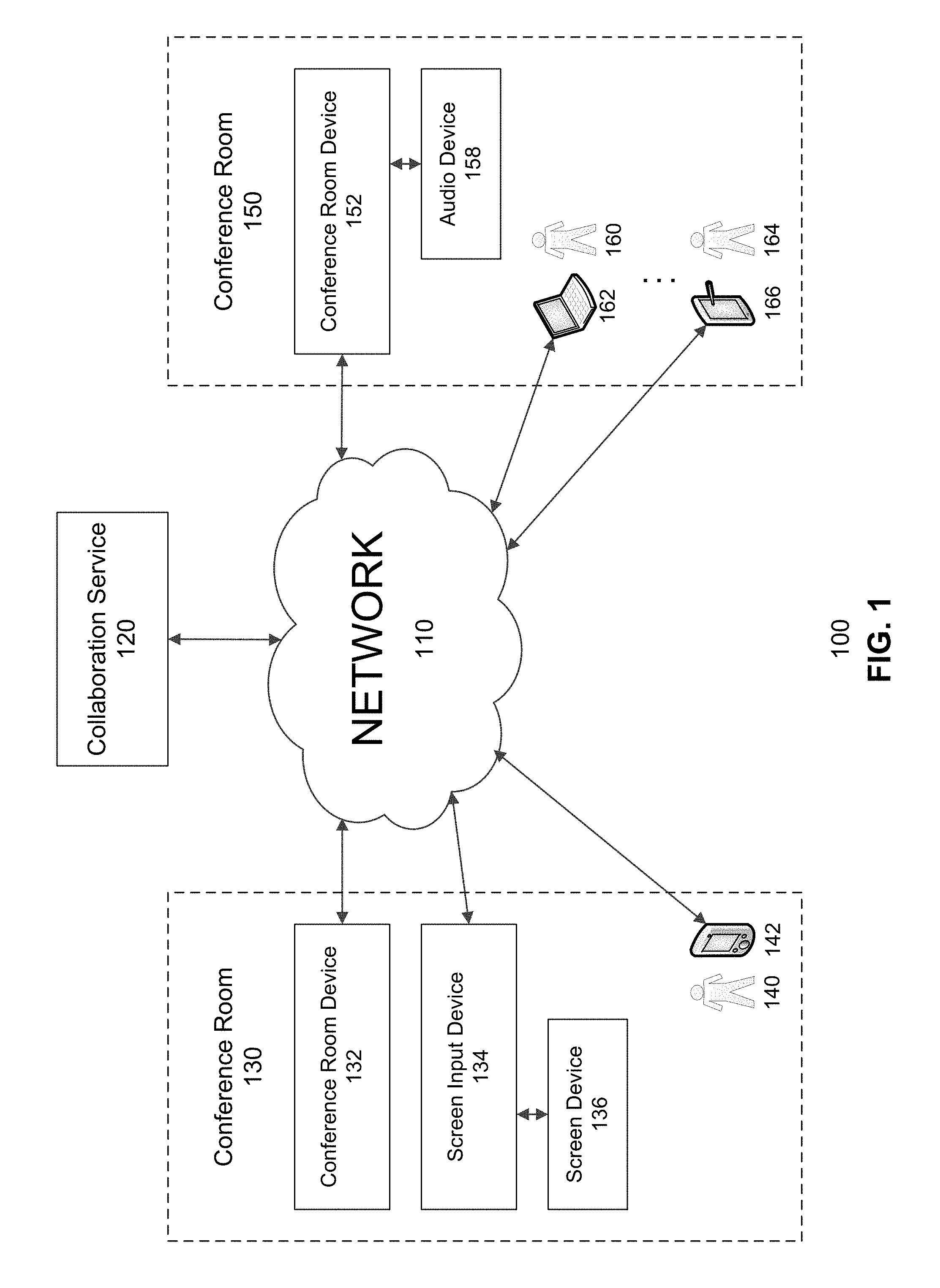
FIG. 1 is a conceptual block diagram illustrating an example network environment for providing conferencing capabilities, in accordance with various embodiments of the subject technology;
FIG. 2 is an illustration of a conference room device, in accordance with various embodiments;
FIG. 3 is conceptual block diagram illustrating a collaboration service, in accordance with various embodiments;
FIG. 4 shows an example conference room according to some embodiments;
FIG. 5 shows an example method for starting a conference meeting according to some embodiments; and
FIGS. 6A and 6B show example possible system embodiments.
DESCRIPTION OF EXAMPLE EMBODIMENTS
Various embodiments of the disclosure are discussed in detail below. While specific implementations are discussed, it should be understood that this is done for illustration purposes only. A person skilled in the relevant art will recognize that other components and configurations may be used without parting from the spirit and scope of the disclosure.
Overview:
The disclosed technology addresses the need in the art for a conference room device configured to aid the initiation, organization, and management of a conference meeting.
Multiparty conferencing technologies simulate in-person interactions and allow participants from multiple geographic locations to collaborate. However, setting a conferencing session or conference meeting up and starting the session is complicated and often takes a number of steps performed by one or all meeting participants. Before each session, each geographic location that will be represented in the conferencing session typically needs to set up all equipment (e.g., audio equipment, video equipment, presentation equipment) so that they are able to work together. When the session is about to begin, a user at each geographic location needs to follow a set of instructions to start the session at that location and "join the meeting."
Various aspects of the subject technology relate to facilitating the setting up or initiation of a conferencing session by detecting when a user comes within range of a conference room device, determining that there is a meeting for the user, and prompting the user to start the meeting. If the user indicates that the user wishes to start the meeting, various embodiments of the subject technology will work to start the conferencing session. By predicting that the user will want to join a conferencing session and proactively prompting the user to begin the conferencing session, various embodiments of the subject technology aid the user in setting up and initiating the conferencing session. The user experience is greatly improved with a simpler, faster, and more intuitive process for initiating the conferencing session.
DETAILED DESCRIPTION
FIG. 1 is a conceptual block diagram illustrating an example network environment 100 for providing conferencing capabilities, in accordance with various embodiments of the subject technology. Although FIG. 1 illustrates a client-server network environment 100, other embodiments of the subject technology may include other configurations including, for example, peer-to-peer environments.
The network environment 100 includes at least one collaboration service 120 server that is in communication with devices from one or more geographic locations. In FIG. 1, the geographic locations include conference room 130 and conference room 150. However, as will be appreciated by those skilled in the art, the communication devices do not necessarily need to be in a room.
The various devices and the collaboration service 120 communicate via a network 110 (e.g., the Internet). The network 110 can be any type of network and may include, for example, any one or more of a cellular network, a satellite network, a personal area network (PAN), a local area network (LAN), a wide area network (WAN), a broadband network (BBN), the Internet, and the like. Further, the network 150 can include, but is not limited to, any one or more of the following network topologies, including a bus network, a star network, a ring network, a mesh network, a star-bus network, tree or hierarchical network, and the like. Network 110 can be a public network, a private network, or a combination thereof. Communication network 110 may be implemented using any number of communications links associated with one or more service providers, including one or more wired communication links, one or more wireless communication links, or any combination thereof. Additionally, network 110 can be configured to support the transmission of data formatted using any number of protocols.
Conference room 130 includes a conference room device 132, a screen input device 134 (or a screen assistive device), and a screen device 136. The screen device 136 may be a monitor, a television, a projector, a tablet screen, or other visual device that may be used during the conferencing session. The screen input device 134 is configured to interface with the screen device 136 and provide the conferencing session input for the screen device 136. The screen input device 134 may be integrated into the screen device or separate from the screen input device 134 and communicate with the screen input device via a Universal Serial Bus (USB) interface, a High-Definition Multimedia Interface (HDMI) interface, a computer display standard interface (e.g., Video Graphics Array (VGA), Extended Graphics Array (XGA), etc.), a wireless interface (e.g., Wi-Fi, infrared, Bluetooth, etc.), or other input or communication medium. In some embodiments, screen input device 134 may be integrated into conference room device 132.
The conference room device 132 is configured to detect when a user comes within range of the conference room 130, the conference room device 132, or some other geographic location marker. The conference room device 132 is further configured to coordinate with the other devices in the conference room 130 or geographical location and the collaboration service 120 to start and maintain a conferencing session. For example, the conference room device 132 may interact with a client device associated with one or more user to facilitate a conferencing session. The client device may be, for example, a user's smart phone, tablet, laptop, or other computing device.
As shown in FIG. 1, conference room 130 further includes one or more users 140. Each user may be associated with one or more client devices 142. The client devices 142 may include smart phones, tablets, laptop computers, conferencing devices, or other computing devices. The client devices 142 may have an operating system and run one or more collaboration applications that facilitate conferencing or collaboration. For example, a collaboration application running on a client device 142 may be configured to interface with the collaboration service 120 or the conference room device 132 in facilitating a conferencing session for a user.
Conference room 150 includes a conference room device 152, an audio device 158, one or more users (user 160 and user 164), and one or more client devices 162 and 166. Conference room 150 is not shown with a screen device or a screen input device because some geographic locations may not have access to these devices.
The audio device 158 may include one or more speakers, microphones, or other audio equipment that may be used during the conferencing session. The conference room device 152 is configured to interface with the audio device 158 and provide the conferencing session input for the audio device 158. The audio device 158 may be integrated into the conference room device 152 or separate from the conference room device 152 and communicate with the conference room device 152 via an audio cable interface, a Universal Serial Bus (USB) interface, a High-Definition Multimedia Interface (HDMI) interface, a wireless interface (e.g., Wi-Fi, infrared, Bluetooth, etc.), or other input or communication medium.
FIG. 2 is an illustration of a conference room device 200, in accordance with various embodiments. The conference room device 200 may include a processor 210 and a computer-readable medium 220 storing instructions that, when executed by the conference room device 200, cause the conference room device 200 to perform various operations for facilitating a conferencing session. The conference room device 200 may further include a pairing interface 230, and audio interface, and a network interface 250. The network interface 250 may be configured to facilitate conferencing sessions by communicating with a collaboration service, screen input device, or client device.
The pairing interface 230 may be configured to detect when a user is within range of the conference room, the conference room device 200, or some other geographic location marker. For example, the pairing interface 230 may determine when the user is within a threshold distance of the conference room device 200 or when the user is within range of a sensor of the conference room device 200. The pairing interface may include one or more sensors including, an ultrasonic sensor, a time-of-flight sensor, a microphone, a Bluetooth sensor, a near-field communication (NFC) sensor, or other range determining sensors.
An ultrasonic sensor may be configured to generate sound waves. The sound waves may be high frequency (e.g., frequencies in the ultrasonic range that are beyond the range of human hearing). However, in other embodiments, other frequency ranges may be used. In some embodiments, the sound waves may be encoded with information such as a current time and a location identifier. The location identifier may be, for example, a conference room device 200 identifier, a geographic location name, coordinates, etc. The ultrasonic sound waves encoded with information may be considered an ultrasonic token.
A client device may detect the ultrasonic token and inform a collaboration service that the client device detected the ultrasonic token from the conference room device 200. The collaboration service may check the ultrasonic token to make sure the sound waves were received at the appropriate time and location. If the client device received the ultrasonic token at the appropriate time and location, the collaboration service may inform the conference room device 200 that the client device is within range and pair the conference room device 200 with the client device.
In other embodiments, the conference room device 200 and the client device may pair together directly, without the assistance of a collaboration service. Furthermore, in some embodiments, the roles are reversed where the client device emits high frequency sound waves and the ultrasonic sensor of the conference room device detects the high frequency sound waves from the client device. In still other embodiments, an ultrasonic sensor may be configured to generate high frequency sound waves, detect an echo which is received back after reflecting off a target, and calculate the time interval between sending the signal and receiving the echo to determine the distance to the target. A time-of-flight sensor may be configured to illuminate a scene (e.g., a conference room or other geographic location) with a modulated light source and observe the reflected light. The phase shift between the illumination and the reflection is measured and translated to distance.
The audio interface 240 may be configured to provide the audio component to the conferencing session. For example, the audio interface 240 may receive audio from participants in one geographic location of the conferencing session and play the audio from participants in another geographic location. The audio interface 240 may also be configured to facilitate the conferencing session by providing and receiving audio from meeting participants, client devices, or the collaboration service. In some embodiments, the audio interface 240 may prompt the user to start a meeting, prompt the user to end a meeting, prompt the user for instructions, or receive instructions from meeting participants. The audio interface 240 may include one or more speakers, microphones, or other audio equipment. In other embodiments, the audio interface 240 may interface with one or more speakers, microphones, or other audio devices external to the conference room device 200.
FIG. 3 is conceptual block diagram illustrating a collaboration service 300, in accordance with various embodiments. The collaboration service may include a pairing module 310, a scheduling module 320, and a conferencing module 330.
The pairing module 310 may be configured to aid the pairing of a client device and a conference room device or the detection of a user within range of the conference room device. For example, the pairing module 310 may receive a communication from a client device indicating that the client device received an ultrasonic token from a conferencing room device. The pairing module 310 may decode the ultrasonic token and determine whether the client device received the ultrasonic token at the correct time and place. If the ultrasonic token does not match the appropriate time and place, the pairing module 310 may prevent pairing of the client device and the conferencing room device. If the ultrasonic token matches the appropriate time and place, the pairing module 310 may pair the client device and the conferencing room device. The pairing of the client device and the conferencing room device signifies that the client device and the user associated with the client device are within range of the conference room device.
A scheduling module 320 is configured to identify an appropriate meeting to start based on the paired devices. As will be discussed in further detail below, the scheduling module 320 may identify a user associated with the client device paired with a conference room device at a particular geographic location. The scheduling module 320 may access an electronic calendar for the conference room device at the geographic location, an electronic calendar for the user, or both to determine whether there is a conference meeting or session scheduled for the current time. If there is a meeting or session scheduled, the scheduling module 320 may ask the user if the user wants to start the meeting or session. For example, the scheduling module 320 may instruct the conference room device to prompt the user to start the meeting or instruct a collaboration application on the client device to prompt the user to start the meeting.
An electronic calendar may include a schedule or series of entries for the user, a conference room device, a conference room, or any other resource associated with a conference meeting. Each entry may signify a meeting or collaboration session and include a date and time, a list of one or more participants, a list of one or more locations, or a list of one or more conference resources. The electronic calendar may be stored by the collaboration service 300 or a third party service and accessed by scheduling module 320.
A conferencing module 330 is configured to start and manage a conferencing session between two or more geographic locations. For example, the conference room device may prompt the user to start the meeting and receive a confirmation from the user to start the meeting. The conference room device may transmit the confirmation to the collaboration service 300 and the conferencing module 330 may initiate the conferencing session. In some embodiments, the conferencing module 330 may initiate the conferencing session after the scheduling module 320 identifies an appropriate meeting to start without receiving a confirmation from the user or prompting the user to start the meeting.
In some embodiments, the conference room device may receive and respond to instructions from a user. Instructions may be received by a microphone, other sensor, or interface. For example, the user may enter a room and say "Please start my meeting." The conference room device may receive the instructions via the microphone and transmit the instructions to the collaboration service 300. The collaboration service 300 may convert the speech to text using speech-to-text functionality or third-party service. The collaboration service 300 may user natural language processing to determine the user's intent to start a meeting, identify an appropriate calendar entry for the user or conference room, and start the meeting associated with the calendar entry. In some cases, the collaboration service 300 may further use text-to-speech functionality or service to provide responses back to the user via the conference room device.
FIG. 4 shows an example conference room 400 according to some embodiments. The conference room 400 is shown with a conference room device 410, a screen input device 420, and a screen device 430 located within the conference room 400. In other embodiments, however, conference room 400 may include additional devices (e.g., client devices, audio devices, additional screen devices, etc.), fewer devices, or alternative devices.
The conference room device 410 may be configured to pair with various devices and components in the conference room 400 in order to provide various capabilities for a collaboration session. For example, the conference room device 410 may be configured to pair with any audio devices in the conference room 400 or contain audio components (e.g., one or more speakers or microphones) to provide audio capability for the collaboration session. The conference room device 410 may also pair with a camera or the screen input device 420, which is connected to screen device 430, in order to provide video or presentation capabilities for the collaboration session. The conference room device 410 may be further configured to continue listening during a collaboration session and respond to voice activated commands.
As will be discussed in further detail below, the conference room device 410 may also automatically detect users within range of the conference room device 410, determine whether the user has a meeting, and ask the user to start a meeting. In this way, the conference room device 410 initiates the interaction with the user and guides the user through the initiation of the conference meeting.
FIG. 5 shows an example method 500 for starting a conference meeting according to some embodiments. Although the methods and processes described herein may be shown with certain steps and operations in a particular order, additional, fewer, or alternative steps and operations performed in similar or alternative orders, or in parallel, are within the scope of various embodiments unless otherwise stated.
Method 500 may be implemented by a system which may include a conference room device, a collaboration service, or a combination thereof. At operation 505, the system determines that a conference room device is within range of a user based on a pairing interface of the conference room device. More specifically, in embodiments where the pairing interface is an ultrasonic sensor, the pairing interface may emit a token in the form of high frequency sound waves. The token may include encoded information such as a current time and location information (e.g., a location of the conference room the conference room device is located in or a conference room device identifier).
A user may be associated with a client device (e.g., a smart phone, tablet, laptop, or other device) running a collaboration application. The collaboration application may be logged in to an account for the user that is associated with the collaboration service. The collaboration application may utilize the components of the client device (e.g., a microphone or ultrasonic sensor) to listen for tokens. When the user of the client device comes within range of the conference room device, the collaboration application on the client device may detect and receive the token from the pairing interface of the conference room device.
In response to receiving the token from the pairing interface of the conference room device, the collaboration application on the client device may inform the collaboration service that it has received the token by translating the token and transmitting the encoded information to the collaboration service along with a user identifier (e.g., a user name or user account credentials). In other embodiments, the collaboration application on the client device may inform the collaboration service that it has received the token by transmitting the token to the collaboration service along with the user identifier.
If the collaboration service receives the decoded information from the client device, the collaboration service may confirm that the token is still valid (e.g., that the time encoded in the token is within a threshold time difference from the current time or that the token has not expired). On the other hand, if the collaboration service receives the token, the collaboration service may decode the token and confirm that the token is still valid. The collaboration service may determine whether the token is valid in order to make certain that the user and the user's client device are currently within range of the conference room device instead of merely being delayed in transmitting the token or token information.
At operation 510, the system determines that there is a conference meeting at the current time. In some embodiments, the collaboration service identifies a user account based on the user identifier and identifies the conference room device based on the information encoded in the token emitted by the conference room device. The scheduling module of the collaboration service may access one or more calendars associated with the user account, the conference room device, the conference room that the conference room device is located in, or a combination thereof.
Based on the accessed calendars, the collaboration service may determine whether the user is associated with a conference meeting at the current time. For example, the collaboration service may determine that the user is associated with a conference meeting at the current time based on an entry in the user's calendar at or near the current time, based on an entry in the calendar associated with the conference room or conference room device at or near the current time, or both.
At operation 515, the system prompts the user to start the conference meeting. In some embodiments, the collaboration service may transmit instructions to the conference room device to prompt the user to start the conference meeting. The conference room device may receive the instructions and prompt the user by audibly asking if the user wants to start the conference meeting via the audio interface of the conference room device. For example the audio interface may ask the user "We notice you have an upcoming meeting. Do you want to start your meeting?" In some embodiments, the prompt may include personalized information such as the user's name, the title of the meeting, or other participants of the meeting. Furthermore, in some embodiments, the prompt may also (or alternatively) be provided to the user visually via the screen input device or the application on the client device and the instructions to prompt the user may be transmitted by the conference room device or the collaboration service.
The user may respond to the prompt by speaking (e.g., by saying "Yes, start my meeting") or inputting a response into the collaboration application on the client device. The system receives the user's response at operation 520. The response may be received by the conference room device and transmitted to the collaboration service or received directly by the collaboration service (e.g., from the collaboration application on the client device).
If the response indicates that the user wishes to start the meeting (e.g., a confirmation response to the prompt), the collaboration service will start the conference meeting at operation 525. For example, the collaboration service may initiate two-way communication between the devices in the conference room and devices in conference rooms in one or more other geographic locations. Furthermore, the collaboration may enable additional conference meeting features such as recording, voice commands, video capabilities, shared screens, presentation abilities, or shared collaboration documents.
Although method 500 is described with respect to detecting that one user is within range of a conference room device, it will be appreciated by those in the art that additional users may be detected using similar processes. In some cases, the collaboration service may customize prompts or information provided to users based on the number of users detected. For example, if only one user is detected, the collaboration service may include more personalized information (e.g., the user's name) when communicating with the user.
According to some embodiments, the collaboration service may identify various signals in the calendar information that increase the reliability of a determination that the user is associated with a particular meeting at the current time. For example, there may be an entry in the calendar for the user at the current time and an entry in the calendar for the conference room device at the current time, the entry in the user's calendar may list the conference room or the conference room device as a location or participant, the entry in the calendar of the conference room device may list the user participant, the entries for the user and the conference room device may be part of the same meeting or conferencing session (e.g., they share a common meeting identifier), or the entries for the user and the conference room device may share common participants. Additional signals may be derived from calendar information from other users detected by the conference room device. For example, other detected users may have entries at the current time, the entries may list the first detected user as a participant, the entries may share common users in the participant list, the entries may list the conference room or the conference room device as a location or participant, or the entries may be part of the same meeting or conferencing session. The above information may aid the collaboration service in selecting a conference meeting and determining that the user is associated with the conference meeting.
However, not all calendar information may be consistent and there may be some ambiguity over what meeting is occurring at the current time. For example, the collaboration service may identify two or more entries at the current time in the calendar for the user, two or more entries at the current time in the calendar for the conference room device, or the entry for the conference room device may not list a detected user as a participant. According to some embodiments, the collaboration service may perform disambiguation functions in order to determine which conference meeting is occurring at the current time. In some embodiments, the collaboration service may prompt one of the users within range of the conference room device to select a meeting to start. In some embodiments, the collaboration service may use one or more signals in the calendar information described above to determine which conference meeting to start or to prompt the detected user to start.
According to some embodiments, the collaboration service may determine that there are conflicting entries in one or more calendars. For example, the collaboration service may detect two or more users within range of the conference room device and the scheduling module of the collaboration service may determine that the calendar for one of the detected user two or more entries at the current time. The collaboration service determines if one of the entries is shared by another user within range of the conference room device. If one of the entries is shared by another user, the collaboration service may determine that the shared entry is most likely the meeting that the users intend to attend. The collaboration service may automatically start the meeting associated with the shared entry or prompt one or more of the detected users to start the meeting associated with the shared entry.
In some embodiments, the collaboration service access a list of participants, attendees, or invitees for each of the two or more entries at the current time and determine which entry is for the meeting that the users most likely intend to attend based on the other users detected within range of the conference room device. For example, if User_A has two calendar entries (entry_1 and entry_2) at the current time and the detected users more closely match the participants list for entry_1 than entry_2, the collaboration service may determine that entry_1 is most likely the meeting that the user intends to start. The collaboration service may automatically start the meeting associated with entry_1 or prompt the user to start the meeting associated with entry_1.
In some cases, the collaboration service may determine that the calendar for the conference room device includes two or more entries at the current time. In order to determine which meeting to start, the collaboration service may determine if one of the entries is shared by user that is within range of the conference room device or if the participants list for one of the entries more closely matches the list of users within range of the conference room device.
Various embodiments described herein may include various instances of disambiguation, speech recognition, and text-to-speech that enable a bi-directional interaction and cooperation with a user to initiate a meeting. For example, in one scenario, a user may enter a meeting room that includes a conference room device. The conference room device may detect the user and greet the user. The greeting may be visual (e.g., a video greeting on a screen), textual (a text greeting on the screen or client device), or audible (e.g., a greeting converted from text to speech and played via a speaker on the conference room device). The collaboration service may identify the user, look up a calendar associated with the user, and potentially identify multiple entries for the user at the current time. If multiple entries are found, the conference room device may ask the user "I have found multiple meetings at this time" and list the meetings either textually, audibly (via text-to-speech functionality), or both. The user selects a meeting and the instructions may be converted from speech to text and run through a speech recognition service to determine the user's intent. Once the instructions to start the selected meeting are understood by the collaboration service, the collaboration service may start the selected meeting.
In some embodiments, before a meeting is started, the collaboration service may determine that a user that is detected to be within range of the conference room device is not listed as a participant in the entry for the meeting. Since this may be considered a security issue, the collaboration service may notify the other participants in one or more of the geographic locations about the unlisted user and ask if the participants want to add the unlisted user as a participant to the meeting. Adding the unlisted user as a participant to the meeting may enable the unlisted user to access additional features associated with the conference meeting. For example, an entry for the meeting may be provided to the unlisted user's calendar or the unlisted user may receive any shared documents, presentations, or recordings associated with the meeting.
FIG. 6A, and FIG. 6B show example possible system embodiments. The more appropriate embodiment will be apparent to those of ordinary skill in the art when practicing the present technology. Persons of ordinary skill in the art will also readily appreciate that other system embodiments are possible.
FIG. 6A shows a conventional system bus computing system architecture 600 wherein the components of the system are in electrical communication with each other using a bus 605. Example system 600 includes a processing unit (CPU or processor) 610 and a system bus 605 that couples various system components including the system memory 615, such as read only memory (ROM) 620 and random access memory (RAM) 625, to the processor 610. The system 600 can include a cache of high-speed memory connected directly with, in close proximity to, or integrated as part of the processor 610. The system 600 can copy data from the memory 615 and/or the storage device 630 to the cache 612 for quick access by the processor 610. In this way, the cache can provide a performance boost that avoids processor 610 delays while waiting for data. These and other modules can control or be configured to control the processor 610 to perform various actions. Other system memory 615 may be available for use as well. The memory 615 can include multiple different types of memory with different performance characteristics. The processor 610 can include any general purpose processor and a hardware module or software module, such as module 1 632, module 2 634, and module 3 636 stored in storage device 630, configured to control the processor 610 as well as a special-purpose processor where software instructions are incorporated into the actual processor design. The processor 610 may essentially be a completely self-contained computing system, containing multiple cores or processors, a bus, memory controller, cache, etc. A multi-core processor may be symmetric or asymmetric.
To enable user interaction with the computing device 600, an input device 645 can represent any number of input mechanisms, such as a microphone for speech, a touch-sensitive screen for gesture or graphical input, keyboard, mouse, motion input, speech and so forth. An output device 635 can also be one or more of a number of output mechanisms known to those of skill in the art. In some instances, multimodal systems can enable a user to provide multiple types of input to communicate with the computing device 600. The communications interface 640 can generally govern and manage the user input and system output. There is no restriction on operating on any particular hardware arrangement and therefore the basic features here may easily be substituted for improved hardware or firmware arrangements as they are developed.
Storage device 630 is a non-volatile memory and can be a hard disk or other types of computer readable media which can store data that are accessible by a computer, such as magnetic cassettes, flash memory cards, solid state memory devices, digital versatile disks, cartridges, random access memories (RAMs) 625, read only memory (ROM) 620, and hybrids thereof.
The storage device 630 can include software modules 632, 634, 636 for controlling the processor 610. Other hardware or software modules are contemplated. The storage device 630 can be connected to the system bus 605. In one aspect, a hardware module that performs a particular function can include the software component stored in a computer-readable medium in connection with the necessary hardware components, such as the processor 610, bus 605, display 635, and so forth, to carry out the function.
FIG. 6B shows a computer system 650 having a chipset architecture that can be used in executing the described method and generating and displaying a graphical user interface (GUI). Computer system 650 is an example of computer hardware, software, and firmware that can be used to implement the disclosed technology. System 650 can include a processor 655, representative of any number of physically and/or logically distinct resources capable of executing software, firmware, and hardware configured to perform identified computations. Processor 655 can communicate with a chipset 660 that can control input to and output from processor 655. In this example, chipset 660 outputs information to output 665, such as a display, and can read and write information to storage device 670, which can include magnetic media, and solid state media, for example. Chipset 660 can also read data from and write data to RAM 675. A bridge 680 for interfacing with a variety of user interface components 685 can be provided for interfacing with chipset 660. Such user interface components 685 can include a keyboard, a microphone, touch detection and processing circuitry, a pointing device, such as a mouse, and so on. In general, inputs to system 650 can come from any of a variety of sources, machine generated and/or human generated.
Chipset 660 can also interface with one or more communication interfaces 690 that can have different physical interfaces. Such communication interfaces can include interfaces for wired and wireless local area networks, for broadband wireless networks, as well as personal area networks. Some applications of the methods for generating, displaying, and using the GUI disclosed herein can include receiving ordered datasets over the physical interface or be generated by the machine itself by processor 655 analyzing data stored in storage 670 or 675. Further, the machine can receive inputs from a user via user interface components 685 and execute appropriate functions, such as browsing functions by interpreting these inputs using processor 655.
It can be appreciated that example systems 600 and 650 can have more than one processor 610 or be part of a group or cluster of computing devices networked together to provide greater processing capability.
For clarity of explanation, in some instances the present technology may be presented as including individual functional blocks including functional blocks comprising devices, device components, steps or routines in a method embodied in software, or combinations of hardware and software.
In some embodiments the computer-readable storage devices, mediums, and memories can include a cable or wireless signal containing a bit stream and the like. However, when mentioned, non-transitory computer-readable storage media expressly exclude media such as energy, carrier signals, electromagnetic waves, and signals per se.
Methods according to the above-described examples can be implemented using computer-executable instructions that are stored or otherwise available from computer readable media. Such instructions can comprise, for example, instructions and data which cause or otherwise configure a general purpose computer, special purpose computer, or special purpose processing device to perform a certain function or group of functions. Portions of computer resources used can be accessible over a network. The computer executable instructions may be, for example, binaries, intermediate format instructions such as assembly language, firmware, or source code. Examples of computer-readable media that may be used to store instructions, information used, and/or information created during methods according to described examples include magnetic or optical disks, flash memory, USB devices provided with non-volatile memory, networked storage devices, and so on.
Devices implementing methods according to these disclosures can comprise hardware, firmware and/or software, and can take any of a variety of form factors. Typical examples of such form factors include laptops, smart phones, small form factor personal computers, personal digital assistants, and so on. Functionality described herein also can be embodied in peripherals or add-in cards. Such functionality can also be implemented on a circuit board among different chips or different processes executing in a single device, by way of further example.
The instructions, media for conveying such instructions, computing resources for executing them, and other structures for supporting such computing resources are means for providing the functions described in these disclosures.
Although a variety of examples and other information was used to explain aspects within the scope of the appended claims, no limitation of the claims should be implied based on particular features or arrangements in such examples, as one of ordinary skill would be able to use these examples to derive a wide variety of implementations. Further and although some subject matter may have been described in language specific to examples of structural features and/or method steps, it is to be understood that the subject matter defined in the appended claims is not necessarily limited to these described features or acts. For example, such functionality can be distributed differently or performed in components other than those identified herein. Rather, the described features and steps are disclosed as examples of components of systems and methods within the scope of the appended claims.
* * * * *
References
-
packetizer.com/voip/h323/papers/primer
-
averusa.com/education/downloads/hvcbrochuregoved.pdf
-
323.tv/news/polycom-realpresence-group-series
-
iste.org/docs/excerpts/VIDCO2-excerpt.pdf
-
epson.com/cgi-bin/Store/jsp/Landing/brightlink-pro-interactive-projectors.do?ref=vanbrightlink-pro--dated2013
-
infocus.com/sites/default/files/InFocus-Mondopad-INF5520a-INF7021-Datasheet-EN.pdf
-
informationweek.com/telecom/unified-communications/polycom-adds-tablet-videoconferencing/231900680
-
nu-star.com/interactive-conf.php
-
polycom.com/products-services/hd-telepresence-video-conferencing/realpresence-mobile.htm#stab1
-
-
uatg.com/pdf/polycom/polycom-uc-boarddatasheet.pdf
-
vidyo.com/products/vidyopanorama
-
ibm.com/developerworks/lotus/library/sametime8-new/10pages
D00000
D00001
D00002
D00003
D00004
D00005
D00006
XML
uspto.report is an independent third-party trademark research tool that is not affiliated, endorsed, or sponsored by the United States Patent and Trademark Office (USPTO) or any other governmental organization. The information provided by uspto.report is based on publicly available data at the time of writing and is intended for informational purposes only.
While we strive to provide accurate and up-to-date information, we do not guarantee the accuracy, completeness, reliability, or suitability of the information displayed on this site. The use of this site is at your own risk. Any reliance you place on such information is therefore strictly at your own risk.
All official trademark data, including owner information, should be verified by visiting the official USPTO website at www.uspto.gov. This site is not intended to replace professional legal advice and should not be used as a substitute for consulting with a legal professional who is knowledgeable about trademark law.