Control line retainer for a downhole tool
Goodman Dec
U.S. patent number 10,513,921 [Application Number 15/362,987] was granted by the patent office on 2019-12-24 for control line retainer for a downhole tool. This patent grant is currently assigned to WEATHERFORD TECHNOLOGY HOLDINGS, LLC. The grantee listed for this patent is Weatherford Technology Holdings, LLC. Invention is credited to Brandon C. Goodman.


| United States Patent | 10,513,921 |
| Goodman | December 24, 2019 |
Control line retainer for a downhole tool
Abstract
A method of coupling a control line to a packer includes disposing the control line in a groove of a sealing element and a slot of a retainer; and rotating the retainer relative to the sealing element to retain the control line in the groove.
| Inventors: | Goodman; Brandon C. (Houston, TX) | ||||||||||
|---|---|---|---|---|---|---|---|---|---|---|---|
| Applicant: |
|
||||||||||
| Assignee: | WEATHERFORD TECHNOLOGY HOLDINGS,
LLC (Houston, TX) |
||||||||||
| Family ID: | 60805739 | ||||||||||
| Appl. No.: | 15/362,987 | ||||||||||
| Filed: | November 29, 2016 |
Prior Publication Data
| Document Identifier | Publication Date | |
|---|---|---|
| US 20180148997 A1 | May 31, 2018 | |
| Current U.S. Class: | 1/1 |
| Current CPC Class: | E21B 17/1035 (20130101); E21B 47/12 (20130101); E21B 33/1208 (20130101) |
| Current International Class: | E21B 47/12 (20120101); E21B 33/12 (20060101); E21B 17/10 (20060101) |
References Cited [Referenced By]
U.S. Patent Documents
| 2177203 | October 1939 | Bradley |
| 2253092 | August 1941 | Pranger |
| 2739650 | March 1956 | Hill |
| 3899631 | August 1975 | Clark |
| 4042023 | August 1977 | Fox |
| 4627490 | December 1986 | Moore |
| 4852649 | August 1989 | Young |
| 4917187 | April 1990 | Burns et al. |
| 5096209 | March 1992 | Ross |
| 5184677 | February 1993 | Dobscha |
| 5226485 | July 1993 | Dobscha et al. |
| 5377444 | January 1995 | Gibney, Sr. |
| 5479991 | January 1996 | Robison et al. |
| 5803170 | September 1998 | Garcia-Soule et al. |
| 5906240 | May 1999 | Kilgore et al. |
| 6026897 | February 2000 | Pringle et al. |
| 6109357 | August 2000 | Zimmerman |
| 6173788 | January 2001 | Lembcke et al. |
| 6220362 | April 2001 | Roth et al. |
| 6286603 | September 2001 | Parent |
| 6325144 | December 2001 | Turley et al. |
| 6481496 | November 2002 | Jackson et al. |
| 6568481 | May 2003 | Koehler et al. |
| 6575251 | June 2003 | Watson et al. |
| 6595292 | July 2003 | Purkis et al. |
| 6609567 | August 2003 | Ingram et al. |
| 6745844 | June 2004 | Henderson |
| 6808024 | October 2004 | Schwendemann et al. |
| 6877553 | April 2005 | Cameron |
| 7191828 | March 2007 | Arizmendi et al. |
| 7201226 | April 2007 | Gambier |
| 7216720 | May 2007 | Zimmerman |
| 7228912 | June 2007 | Patel et al. |
| 7264061 | September 2007 | Dybevik et al. |
| 7281577 | October 2007 | Rioufol et al. |
| 7431082 | October 2008 | Holt et al. |
| 7441605 | October 2008 | Coronado et al. |
| 7458420 | December 2008 | Rioufol et al. |
| 7510017 | March 2009 | Howell et al. |
| 7556093 | July 2009 | Grigsby et al. |
| 7562709 | July 2009 | Saebi et al. |
| 7699115 | April 2010 | Baaijens et al. |
| 7703507 | April 2010 | Strickland |
| 7748459 | July 2010 | Johnson |
| 7762322 | July 2010 | Andersen |
| 7762344 | July 2010 | Courville et al. |
| 7784532 | August 2010 | Sevre et al. |
| 7793718 | September 2010 | Patel et al. |
| 7832471 | November 2010 | Verzwyvelt et al. |
| 7836960 | November 2010 | Patel et al. |
| 7841409 | November 2010 | Gano et al. |
| 7866708 | January 2011 | Johnson et al. |
| 7878252 | February 2011 | Smith et al. |
| 7896070 | March 2011 | Lovell |
| 7913769 | March 2011 | Bolding et al. |
| 7997338 | August 2011 | Foster et al. |
| 8006773 | August 2011 | Courville et al. |
| 8082990 | December 2011 | Lovell et al. |
| 8083000 | December 2011 | Nutley et al. |
| 8225861 | July 2012 | Foster et al. |
| 8256508 | September 2012 | Bolding et al. |
| 8312934 | November 2012 | Coronado |
| 8371374 | February 2013 | Foster et al. |
| 8434571 | May 2013 | Kannan et al. |
| 8596369 | December 2013 | Andersen et al. |
| 2007/0012436 | January 2007 | Freyer |
| 2007/0158060 | July 2007 | Baaijens et al. |
| 2009/0250228 | October 2009 | Loretz et al. |
| 2010/0065284 | March 2010 | Freyer |
| 2010/0230902 | September 2010 | Castillo et al. |
| 2010/0236775 | September 2010 | Sevre et al. |
| 2010/0236779 | September 2010 | Nutley et al. |
| 2011/0056706 | March 2011 | Brooks |
| 2011/0259579 | October 2011 | Foster et al. |
| 2013/0008643 | January 2013 | Castillo et al. |
| 2013/0146311 | June 2013 | Hathcoat et al. |
| 2014/0227923 | August 2014 | Snyder, II |
| 2506923 | Jul 2004 | CA | |||
| 1554459 | Jul 2005 | EP | |||
| 2004057715 | Jul 2004 | WO | |||
| 2011/012838 | Feb 2011 | WO | |||
Other References
|
UK Combined Search and Examination Report dated Mar. 15, 2018, for United Kingdom Patent Application No. GB1719219.6. cited by applicant. |
Primary Examiner: Andrews; D.
Attorney, Agent or Firm: Patterson + Sheridan, LLP
Claims
I claim:
1. A method of coupling a control line to a packer, comprising: disposing the control line in a groove of a sealing element and a slot of a retainer, wherein the slot has an offset alignment with a radius of the retainer; and rotating the retainer relative to the sealing element to retain the control line in the groove.
2. The method of claim 1, further comprising: disposing a second control line in a second groove of the sealing element and the slot; and rotating the retainer relative to the sealing element to move the second control line from a first position in the second groove to a second position in the second groove.
3. The method of claim 2, wherein the slot intersects the groove and the second groove.
4. The method of claim 1, wherein rotating the retainer relative to the sealing element moves the control line from a first depth in the groove to a second depth in the groove.
5. The method of claim 1, wherein the sealing element and the retainer are disposed around a mandrel.
6. The method of claim 1, wherein the retainer is rotatable relative to and axially fixed to a mandrel.
7. The method of claim 1, wherein the groove is a first groove and is aligned radially in the sealing element.
8. The method of claim 7, wherein a second groove is aligned radially in the sealing element.
9. The method of claim 1, further comprising after rotating the retainer to move the control line in the groove, locking the retainer from further rotational movement.
10. The method of claim 1, further comprising axially fixing the retainer relative to the sealing element prior to disposing the control line in the groove of the sealing element and the slot of the retainer.
11. The method of claim 1, further comprising swelling the sealing element to at least narrow the groove.
12. The method of claim 1, further comprising rotating the retainer until an opening of the slot is aligned with an opening of a second groove.
13. The method of claim 1, wherein rotating the retainer moves the control line along a depth of the groove.
14. A packer, comprising: a mandrel; a sealing element disposed around the mandrel; a longitudinal groove formed along the sealing element for receiving a line; and a retainer disposed around the mandrel and rotatable relative thereto, the retainer having a slot configured to receive the line, wherein the slot is rotatable relative to the groove to retain the line in the groove, and wherein the slot has an offset alignment with a radius of the retainer.
15. The packer of claim 14, wherein the slot is straight.
16. The packer of claim 14, wherein the slot includes a curvature.
17. The packer of claim 14, wherein the retainer is axially fixed relative to the mandrel.
18. The packer of claim 14, wherein the slot, when rotated, is configured to move the line from a first depth in the groove to a second depth in the groove.
19. The packer of claim 14, further comprising a second groove formed along the sealing element to receive a second line.
20. The packer of claim 19, wherein the slot is rotatable relative to the second groove to move the second line from a first depth in the groove to a second depth in the second groove.
21. The packer of claim 19, wherein the two grooves have different depths.
22. The packer of claim 14, further comprising a wire disposed between the retainer and the mandrel to axially fix the retainer relative to the mandrel.
23. The packer of claim 14, further comprising a second retainer, and the sealing element is disposed between the two retainers.
24. The packer of claim 14, wherein the line is configured to transmit at least one of electricity, fluid, and data.
25. The packer of claim 14, wherein the groove is radially aligned.
26. The packer of claim 14, wherein the retainer moves the line along a depth of the groove as the slot is rotated.
Description
BACKGROUND OF THE INVENTION
Field of the Invention
The present invention relates to apparatus and methods of installing a line on a downhole tool.
Description of the Related Art
A packing element is used on a downhole tool of a tubing string to create zonal isolation, for example, between production zones during hydraulic fracturing and during the production of an oil or gas well. In some implementations, various types of lines may be run along the tubing string and may need to pass the isolation provided by the packing element. Typically, the line can be a fiber optic cable used to convey data, or the line can be a hydraulic control line or the like.
One way to pass the line past the packing element involves positioning the line between the tool's mandrel and the internal dimension of the packing element. In this arrangement, the sealing abilities of the packing element are not particularly affected, and the packing element can help protect the line during run in. However, for some types of lines, such as continuous feed-through lines, integrating the line in this arrangement requires the packing element and the line to be assembled on the rig before deployment, which can be tedious and can delay operations. In addition, being able to use a continuous feed-through line that does not have any connectors and the like can be complicated. Overall, integrating a line on the packing element requires special considerations that typically equate to rig time, cost, and a restriction in the type of feed-through mechanism employed.
One method of passing a continuous control line is using split gauge rings that are assembled on the packer on the rig floor, or gauge rings that are only partially assembled on the rig floor with addition of steel plates with bolts. Split gauge rings can be expensive in their manufacture. Also, split gauge rings for a large tool size may become problematic to handle due to their weight. Gauge rings utilizing plates and bolts are also problematic as they may not have sufficient strength to securely hold the control lines in certain applications and well environments.
Further, split gauge rings are complex to manufacture, which may result in excessive material loss and high manufacturing costs. The bolts for affixing the halves of the gauge ring about the mandrel may be susceptible to failure under high pressures. These bolts might also fail in configurations where the bulk of the gauge ring is sent to the field affixed to the mandrel, but the control line is secured by a secondary plate against the main gauge ring. Multi-pieced gauge rings on the rig floor may also see issues with parts getting lost or damaged. In larger diameter tools, weight may become an issue as safety regulations may limit how much a worker can lift.
There is a need, therefore, for a more effective way to retain a control line that passes through a downhole tool, such as a packer.
SUMMARY OF THE INVENTION
In one embodiment, a method of coupling a control line to a packer includes disposing the control line in a groove of a sealing element and a slot of a retainer; and rotating the retainer relative to the sealing element to retain the control line in the groove.
In another embodiment, a method of coupling a control line to a packer includes disposing the control line in a groove of a sealing element and a slot of a retainer; and rotating the retainer relative to the sealing element to move the control line from a first position in the groove to a second position in the groove.
In another embodiment, a packer includes a mandrel; a sealing element disposed around the mandrel; a longitudinal groove formed along the sealing element for receiving a line; a retainer disposed around the mandrel and rotatable relative thereto, the retainer having a slot configured to receive the line, wherein the slot is rotatable relative to the groove to move the line from a first position in the groove to a second position in the groove.
BRIEF DESCRIPTION OF THE DRAWINGS
So that the manner in which the above recited features of the present invention can be understood in detail, a more particular description of the invention, briefly summarized above, may be had by reference to embodiments, some of which are illustrated in the appended drawings. It is to be noted, however, that the appended drawings illustrate only typical embodiments of this invention and are therefore not to be considered limiting of its scope, for the invention may admit to other equally effective embodiments.
FIG. 1 is a perspective view of an exemplary embodiment of a packer. FIG. 1A is a cross-sectional view of the packer. FIG. 1B is a cross-sectional view of the packer taken at line 1B-1B. FIG. 1C is a perspective view of the right side of packer.
FIG. 2 is a perspective view of the packer of FIG. 1 rotated ninety degrees. FIG. 2A is a cross-sectional view of the packer. FIG. 2B is a cross-sectional view of the packer taken at line 2B-2B. FIG. 2C is a perspective view of the left side of packer.
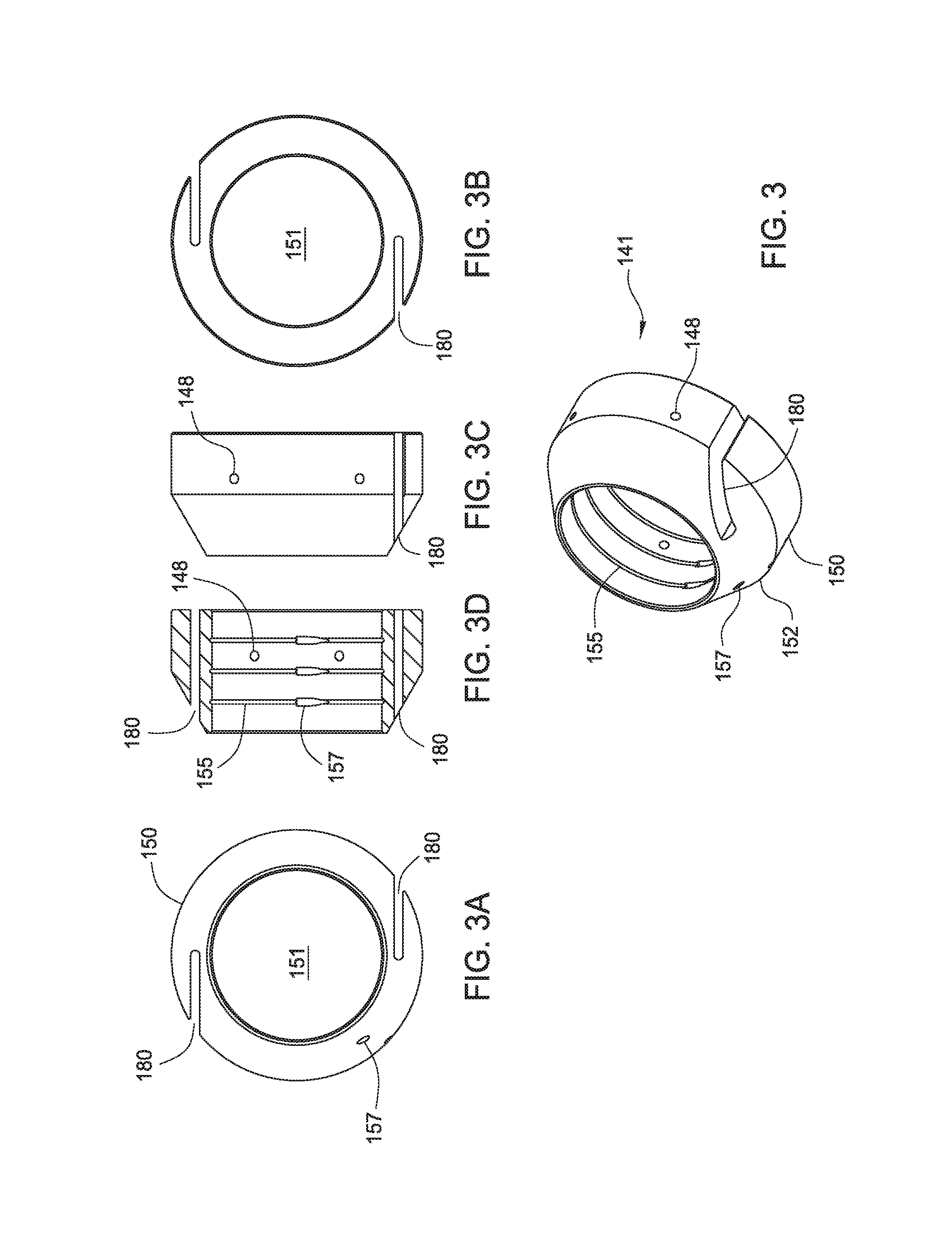
FIG. 3 is a perspective view of an exemplary embodiment of a retainer. FIGS. 3A and 3B are, respectively, a top view and a bottom view of the retainer. FIGS. 3C and 3D are, respectively, a side view and a cross-sectional view of the retainer.
FIGS. 4A-4D are schematic, sequential views of a process for installing a control line in the packer.
FIG. 5 illustrates an example of a slot in the retainer.
FIG. 6 illustrates another example of a slot in the retainer.
FIG. 7 illustrates another example of a slot in the retainer.
DETAILED DESCRIPTION OF THE PREFERRED EMBODIMENT
Embodiments of the present disclosure relates to a retainer for use with a downhole tool to retain a control line passing through the downhole tool, such as a packer. In this disclosure "control lines" or "lines" is used generally and relates to any line, cord, wire, cable, etc. that runs from one end of a tubular string towards an opposite end.
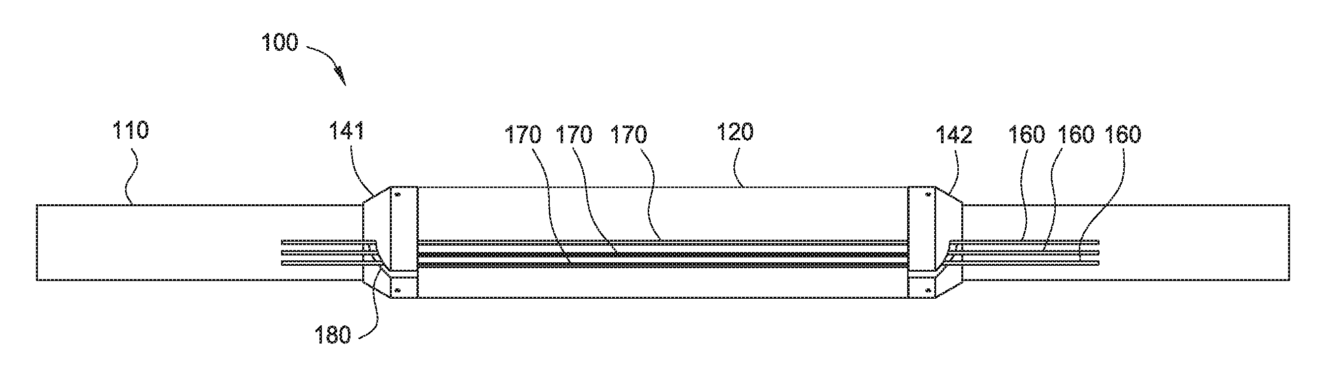
FIG. 1 is a perspective view of an exemplary embodiment of a downhole tool such as a packer 100. FIG. 1A is a cross-sectional view of the packer 100. FIG. 1B is a cross-sectional view of the packer 100 taken at line 1B-1B. FIG. 1C is a perspective view of the right side of packer 100. FIG. 2 is a perspective view of the packer 100 of FIG. 1 rotated ninety degrees. FIG. 2A is a cross-sectional view of the packer 100. FIG. 2B is a cross-sectional view of the packer 100 taken at line 2B-2B. FIG. 2C is a perspective view of the left side of packer 100. The packer 100 includes a mandrel 110, a sealing element 120 disposed on the mandrel 110, and a retainer 141, 142 disposed on the mandrel 110 at each end of the sealing element 120.
The sealing element 120 includes one or more grooves 170 formed into the outer surface and configured to receive a control line 160. The grooves 170 extend longitudinally from one end of the sealing element 120 to the other end. In this embodiment, the sealing element 120 includes two sets of three grooves 170, each groove 170 having a control line 160 disposed therein. While six grooves 170 are shown, it must be noted the sealing element 120 may have any suitable number of grooves to accommodate the control lines required for a particular application. For example, the sealing element 120 may have any of one to twelve or more grooves. The sealing element 120 is composed of an elastomeric material. In one embodiment, the elastomeric material may swell when it contacts a particular fluid, such as a wellbore fluid. The sealing element 120 is configured to swell sufficiently so that it contacts a surrounding tubular, thereby sealing the annular area between the mandrel 110 and the surrounding tubular, such as a casing. The sealing element 120 may also serve to cover the control line 160 when the sealing element 120 swells, thereby blocking at least a portion of the groove 170 to keeping the control line 160 in the groove 170. In one embodiment, swelling of the sealing element closes the groove 170.
Referring back to FIG. 1B, the two sets of grooves 170 in the packer 100 are substantially similar, and for sake of clarity, only one set will be discussed. Each of the three grooves 170a, 170b, 170c has alignment in the radial direction and a different depth. The different depths allow the control line 160 to rest against the bottom of the groove 170 when retained by the retainer 141. In this embodiment, each subsequent groove 170b receiving a control line 160b has a shallower depth than the previous groove 170a receiving a control line 160a. However, it is contemplated the grooves 170 may have the same or different depths. In another embodiment, the grooves 170 may have an offset alignment with the radius.
FIG. 3 is a perspective view of an exemplary embodiment of a retainer 141. FIGS. 3A and 3B are, respectively, a top view and a bottom view of the retainer 141. FIGS. 3C and 3D are, respectively, a side view and a cross-sectional view of the retainer 141. The retainer 141 has a tubular body 150 and a bore 151 formed therethrough. The retainer 141 is disposed around the mandrel 110, and the bottom end is disposed adjacent to the sealing element 120. The top portion 152 of the retainer 141 may have an optional conical shape to facilitate movement in the casing. The retainer 141 is rotatable relative to the mandrel 110. In one embodiment, as shown in FIGS. 3 and 3D, the retainer 141 includes one or more circumferential grooves 155 formed on an inner surface of the bore 151. The circumferential grooves 155 are complementary to a respective circumferential groove 156 formed on the mandrel 110, which are shown in FIG. 1A. Although the retainer 141 is shown with three circumferential grooves 155, the retainer 141 may have one, two, four or more grooves 155. A wire 166 may be disposed between the complementary circumferential grooves 155, 156 to axially locate the retainer 141 on the mandrel 110. In one embodiment, the wire 166 can be inserted into the grooves 155, 156 from the exterior of the retainer 141 via a hole 157 formed through the retainer 141. The retainer 141 can include a locking mechanism to prevent rotation of the retainer 141 relative to the mandrel 110. In one embodiment, a locking member such as a screw may be inserted through a hole 148 in the retainer body 150.
One or more slots 180 are formed in the body 150 to accommodate the control line 160. As shown in FIGS. 3A and 3D, the slot 180 extends longitudinally from one end of the retainer 141 to the other end and extends inwardly from the exterior surface of the sealing element 120. The slot 180 is configured to cross the grooves 170 on the sealing element 120 when the retainer 141 is rotated relative to the sealing element 120. In one example, the slot 180 has a radially offset alignment when the grooves 170 are aligned radially. In another example, the slot 180 and the grooves 170 have different radially offset alignments. The FIG. 3A shows the slot 180 as a straight slot 180. However, the slot 180 may include a curvature. In one embodiment, a width of the slot 180 is sufficient to accommodate the outer diameter of at least one line.
In one embodiment, the one or more control line grooves 170a-c are machined into the sealing element 120 such as an elastomer. The grooves 170a-c run axially through the sealing element 120 and substantially parallel to the mandrel's 110 length. The retainer 141 is disposed around the mandrel 110 and secured to the mandrel 110. For example, a wire is inserted between the circumferential grooves 156, 157 of the mandrel 110 and the retainer 141 to axially fix the retainer 141 while allowing the retainer 141 to rotate relative to the mandrel 110. In another embodiment, a protrusion may be provided on the mandrel to act as end stops to limit at axial movement of the retainer 141. For example, a ring or an arcuate portion of a ring can be attached to the mandrel just above the retainer 141 to limit axial movement of the retainer 141. The packer 100 may be assembled at the rig location or offsite.
In operation, the opening of the slot 180 of the retainer 141 is aligned with the opening of the first groove 170a of the sealing element 120, as shown in FIG. 4A. The first control line 160a is positioned along the first groove 170a and in the aligned openings of the slot 180 and the first groove 170a. It must be noted that more than one control line may be disposed in each groove. The control line may be configured to transmit at least one of electricity, fluid, and data.
The retainer 141 is rotated relative to the first groove 170a to pull the first control line 160a into the first groove 170a, as shown in FIG. 4B. In addition, the rotated retainer 141 prevents the control line 160a from coming out of the first groove 170a. These steps can be repeated with the second retainer 142 at the other end of the sealing element 120 to retain the first control line 160a in the first groove 170a. In an example where there is only one groove in the packer 100, the retainer 141 can be rotationally fixed after the first control line has been pulled into groove 170a. For example, a screw is inserted into the hole 148 in the retainer body 150 to rotationally fix the retainer 141 relative to the mandrel 110.
Referring back to FIG. 4B, the retainer 141 is rotated until the opening in the slot 180 is aligned with the opening in the second groove 170b. The second control line 160b is positioned along the second groove 170b and in the aligned openings of the slot 180 and the second groove 170b.
The retainer 141 is rotated relative to the second groove 170b to pull the second control line 160b into the second groove 170b, as shown in FIG. 4C. In addition, the second control line 160b is retained in the second groove 170b due to position of the slot 180 relative to the second groove 170b. Rotation of the retainer 141 also moves the first control line 160a lower in the first groove 170a.
The retainer 141 is rotated until the opening in the slot 180 is aligned with the opening in the third groove 170c. The third control line 160c is positioned along the third groove 170c and in the aligned openings of the slot 180 and the third groove 170c.
The retainer 141 is rotated relative to the third groove 170c to pull the third control line 160c into the third groove 170c, as shown in FIG. 4D. In addition, the third control line 160c is prevented from coming out of the third groove 170c by the retainer 141. Rotation of the retainer 141 also moves the first control line 160a and the second control line 160b lower in their respective grooves 170a, 170b. After the retainer 141 has been rotated sufficiently to prevent the third control line 160c from leaving the third groove 170c, the retainer 141 can be rotationally fixed relative to the mandrel 110. In the embodiment of FIG. 4D, the retainer 141 is rotated until the slot 180 is about 90 degrees relative to the first groove 170a. The depths of the three grooves 170a-c are configured such that the respective control lines 160a-c are located at or near the bottom of the grooves 170a-c after rotating the retainer 141. Set screws or other suitable fasteners can used to rotationally fix the retainer 141.
The same steps may be repeated using the retainer 142 to install the control lines 160a-c at the other end of the packer 100. Thereafter, the packer 100 is lowered into the wellbore along with the control lines. Upon swelling, the sealing element 120 can fold over the grooves to at least partially narrow the grooves.
In another embodiment, the slot 280 in the retainer 270 is curved, as shown in FIG. 5. The slot 280 may be offset such that the control line is pulled lower into the groove as the retainer 270 is rotated. In another embodiment, a curvature of the slot 285 is configured to allow the control line to remain at a particular position in the groove as the retainer 275 is rotated. In the example shown in FIG. 6, the slot 285 may have the same radial distance along a portion of the curvature. In yet another embodiment, as shown in FIG. 7, the retainer 277 has a slot 287 with an irregular shape or any shape sufficient to retain the control line in the groove.
In one embodiment, a method of coupling a control line to a packer includes disposing the control line in a groove of a sealing element and a slot of a retainer; and rotating the retainer relative to the sealing element to retain the control line in the groove.
In another embodiment, a method of coupling a control line to a packer includes disposing the control line in a groove of a sealing element and a slot of a retainer; and rotating the retainer relative to the sealing element to move the control line from a first position in the groove to a second position in the groove.
In another embodiment, a packer includes a mandrel; a sealing element disposed around the mandrel; a longitudinal groove formed along the sealing element for receiving a line; a retainer disposed around the mandrel and rotatable relative thereto, the retainer having a slot configured to receive the line, wherein the slot is rotatable relative to the groove to move the line from a first position in the groove to a second position in the groove.
In another embodiment, a packer includes a mandrel; a sealing element disposed around the mandrel; a longitudinal groove formed along the sealing element for receiving a line; a retainer disposed around the mandrel and rotatable relative thereto, the retainer having a slot configured to receive the line, wherein the slot is rotatable relative to the groove to retain the line in the groove.
In one or more of the embodiments described herein, the method includes disposing a second control line in a second groove of the sealing element and the slot; and rotating the retainer relative to the sealing element to move the second control line from a first position in the second groove to a second position in the second groove.
In one or more of the embodiments described herein, the method includes disposing a third control line in a third groove of the sealing element and the slot; and rotating the retainer relative to the sealing element to move the third control line from a first position in the third groove to a second position in the third groove.
In one or more of the embodiments described herein, the sealing element and the retainer are disposed around a mandrel.
In one or more of the embodiments described herein, the retainer is rotatable relative to and axially fixed to a mandrel.
In one or more of the embodiments described herein, the groove is a first groove and is aligned radially in the sealing element.
In one or more of the embodiments described herein, a second groove is aligned radially in the sealing element.
In one or more of the embodiments described herein, the first groove and the second groove have different depths.
In one or more of the embodiments described herein, the slot is positioned about 90 degrees relative to the groove after rotation.
In one or more of the embodiments described herein, the method includes swelling the sealing element to at least narrow the groove.
In one or more of the embodiments described herein, the method includes rotating the retainer until an opening of the slot is aligned with an opening of a second groove.
In one or more of the embodiments described herein, the method includes after rotating the retainer to move the control line in the groove, locking the retainer from further rotational movement.
In one or more of the embodiments described herein, rotating the retainer relative to the sealing element moves the control line from a first position in the groove to a second position in the groove
In one or more of the embodiments described herein, the retainer is axially fixed relative to the sealing element prior to disposing the control line in the groove of the sealing element and the slot of the retainer.
In one or more of the embodiments described herein, a second groove is formed along the sealing element to receive a second line.
In one or more of the embodiments described herein, the slot is rotatable relative to the second groove to move the second line from a first position in the groove to a second position in the second groove.
In one or more of the embodiments described herein, at least two grooves have different depths.
In one or more of the embodiments described herein, the groove is radially aligned.
In one or more of the embodiments described herein, the retainer is axially fixed relative to the mandrel.
In one or more of the embodiments described herein, a wire is disposed between the retainer and the mandrel to axially fix the retainer relative to the mandrel.
In one or more of the embodiments described herein, the slot has an offset alignment with a radius of the retainer.
In one or more of the embodiments described herein, the sealing element is disposed between the two retainers.
In one or more of the embodiments described herein, the slot is straight.
In one or more of the embodiments described herein, the slot includes a curvature.
In one or more of the embodiments described herein, the line is configured to transmit at least one of electricity, fluid, and data.
In one or more of the embodiments described herein, the line is selected from the group consisting of cord, wire, and cable.
In one or more of the embodiments described herein, the line is one of a fiber optic cable, electrical line, and a hydraulic line.
While the foregoing is directed to embodiments of the present invention, other and further embodiments of the invention may be devised without departing from the basic scope thereof, and the scope thereof is determined by the claims that follow.
* * * * *
D00000
D00001
D00002
D00003
D00004
D00005
D00006
D00007
D00008
XML
uspto.report is an independent third-party trademark research tool that is not affiliated, endorsed, or sponsored by the United States Patent and Trademark Office (USPTO) or any other governmental organization. The information provided by uspto.report is based on publicly available data at the time of writing and is intended for informational purposes only.
While we strive to provide accurate and up-to-date information, we do not guarantee the accuracy, completeness, reliability, or suitability of the information displayed on this site. The use of this site is at your own risk. Any reliance you place on such information is therefore strictly at your own risk.
All official trademark data, including owner information, should be verified by visiting the official USPTO website at www.uspto.gov. This site is not intended to replace professional legal advice and should not be used as a substitute for consulting with a legal professional who is knowledgeable about trademark law.