Pump system
Sandahl , et al. Dec
U.S. patent number 10,512,554 [Application Number 15/685,488] was granted by the patent office on 2019-12-24 for pump system. This patent grant is currently assigned to OSSUR ICELAND EHF. The grantee listed for this patent is Ossur Iceland ehf. Invention is credited to Hafsteinn Jonasson, Dana Stewart Marlin, David Sandahl.


| United States Patent | 10,512,554 |
| Sandahl , et al. | December 24, 2019 |
Pump system
Abstract
A prosthetic system includes first and second parts rotatable relative to one another about a joint. The first and second parts are adapted to form at least part of a weight bearing connection between a prosthetic foot and a socket. A pump system includes a pump mechanism operatively connected to the first and second parts. Rotation of the first part and/or the second part about the joint moves the pump mechanism between an original configuration in which the volume of a fluid chamber defined by the pump mechanism is zero or near-zero, and an expanded configuration in which the volume of the fluid chamber is increased.
| Inventors: | Sandahl; David (Reykjavik, IS), Marlin; Dana Stewart (Reykjavik, IS), Jonasson; Hafsteinn (Reykjavik, IS) | ||||||||||
|---|---|---|---|---|---|---|---|---|---|---|---|
| Applicant: |
|
||||||||||
| Assignee: | OSSUR ICELAND EHF (Reykjavik,
IS) |
||||||||||
| Family ID: | 59772797 | ||||||||||
| Appl. No.: | 15/685,488 | ||||||||||
| Filed: | August 24, 2017 |
Prior Publication Data
| Document Identifier | Publication Date | |
|---|---|---|
| US 20180055659 A1 | Mar 1, 2018 | |
Related U.S. Patent Documents
| Application Number | Filing Date | Patent Number | Issue Date | ||
|---|---|---|---|---|---|
| 62379905 | Aug 26, 2016 | ||||
| Current U.S. Class: | 1/1 |
| Current CPC Class: | A61F 2/64 (20130101); A61F 2/68 (20130101); A61F 2/80 (20130101); A61F 2/60 (20130101); F04B 45/04 (20130101); A61F 2002/742 (20130101); A61F 2002/802 (20130101); A61F 2002/745 (20130101); A61F 2002/6614 (20130101); A61F 2002/608 (20130101) |
| Current International Class: | A61F 2/80 (20060101); A61F 2/64 (20060101); A61F 2/66 (20060101); A61F 2/68 (20060101); A61F 2/74 (20060101) |
References Cited [Referenced By]
U.S. Patent Documents
| 708685 | September 1902 | White |
| 980457 | January 1911 | Toles |
| 1288803 | December 1918 | Beck |
| 1586015 | May 1926 | Underwood |
| 2424278 | July 1947 | Kunkel |
| 2464443 | March 1949 | Ganoe et al. |
| 2530285 | November 1950 | Catranis |
| 2533404 | December 1950 | Sharp et al. |
| 2606325 | August 1952 | Nielson et al. |
| 2664572 | January 1954 | Blevens |
| 2671225 | March 1954 | Schoene et al. |
| 2696010 | December 1954 | Robinson |
| 2696011 | December 1954 | Galdik |
| 2790180 | April 1957 | Hauser |
| 2808593 | October 1957 | Andersen |
| 3253600 | May 1966 | Scholl |
| 3322873 | May 1967 | Hitchcock |
| 3377416 | April 1968 | Kandel |
| 3557387 | January 1971 | Ohlenbusch et al. |
| 3631542 | January 1972 | Potter |
| 3712298 | January 1973 | Snowdon et al. |
| 3732578 | May 1973 | Pollack |
| 3751733 | August 1973 | Fletcher et al. |
| 3806958 | April 1974 | Gusev |
| 3858379 | January 1975 | Graves et al. |
| 3889301 | June 1975 | Bonner, Sr. |
| 3895405 | July 1975 | Edwards |
| 3922727 | December 1975 | Bianco |
| 3947156 | March 1976 | Becker |
| 3975350 | August 1976 | Hudgin et al. |
| 3991424 | November 1976 | Prahl |
| 4010052 | March 1977 | Edwards |
| 4106745 | August 1978 | Carrow |
| 4133776 | January 1979 | Pruett et al. |
| 4282325 | August 1981 | Rubenstein et al. |
| 4283800 | August 1981 | Wilson |
| 4314398 | February 1982 | Pettersson |
| 4381768 | May 1983 | Erichsen et al. |
| 4404296 | September 1983 | Schapel |
| 4456642 | June 1984 | Burgdorfer et al. |
| 4466936 | August 1984 | Schapel |
| 4479272 | October 1984 | Beldzidsky |
| 4623354 | November 1986 | Childress et al. |
| 4634446 | January 1987 | Kristinsson |
| 4635626 | January 1987 | Lerman |
| 4655779 | April 1987 | Janowiak |
| 4704129 | November 1987 | Massey |
| 4822371 | April 1989 | Jolly et al. |
| 4828325 | May 1989 | Brooks |
| 4888829 | December 1989 | Kleinerman et al. |
| 4908037 | March 1990 | Ross |
| 4923475 | May 1990 | Gosthnian et al. |
| 5007937 | April 1991 | Fishman et al. |
| 5108455 | April 1992 | Telikicherla |
| 5108456 | April 1992 | Coonan, III |
| 5133776 | July 1992 | Crowder |
| 5139523 | August 1992 | Paton et al. |
| 5163965 | November 1992 | Rasmusson et al. |
| 5201774 | April 1993 | Greene |
| 5211667 | May 1993 | Danforth |
| 5221222 | June 1993 | Townes |
| 5258037 | November 1993 | Caspers |
| 5314497 | May 1994 | Fay et al. |
| 5353525 | October 1994 | Grim |
| 5362834 | November 1994 | Schapel et al. |
| 5376129 | December 1994 | Faulkner et al. |
| 5376131 | December 1994 | Lenze et al. |
| 5376132 | December 1994 | Caspers |
| 5397628 | March 1995 | Crawley et al. |
| 5405407 | April 1995 | Kodama et al. |
| 5480455 | January 1996 | Norvell |
| 5490537 | February 1996 | Hill |
| 5507834 | April 1996 | Laghi |
| 5534034 | July 1996 | Caspers |
| 5549709 | August 1996 | Caspers |
| 5555216 | September 1996 | Drouot |
| 5571208 | November 1996 | Caspers |
| 5593454 | January 1997 | Helmy |
| 5658353 | August 1997 | Layton |
| 5658354 | August 1997 | Norvell |
| 5702488 | December 1997 | Wood et al. |
| 5702489 | December 1997 | Slemker |
| 5709017 | January 1998 | Hill |
| 5728166 | March 1998 | Slemker |
| 5728167 | March 1998 | Lohmann |
| 5728168 | March 1998 | Laghi et al. |
| 5728169 | March 1998 | Norvell |
| 5728170 | March 1998 | Becker et al. |
| 5732578 | March 1998 | Kang |
| 5735906 | April 1998 | Caspers |
| 5807303 | September 1998 | Bays |
| 5830237 | November 1998 | Kania |
| 5846063 | December 1998 | Lakic |
| 5885509 | March 1999 | Kristinsson |
| 5888216 | March 1999 | Haberman |
| 5888230 | March 1999 | Helmy |
| 5888231 | March 1999 | Sandvig et al. |
| 5904721 | May 1999 | Henry et al. |
| 5904722 | May 1999 | Caspers |
| 5931872 | August 1999 | Lohmann |
| 5944760 | August 1999 | Christensen |
| 5980577 | November 1999 | Radis et al. |
| 5984972 | November 1999 | Huston et al. |
| 6007582 | December 1999 | May |
| 6063125 | May 2000 | Arbogast et al. |
| 6066107 | May 2000 | Habermeyer |
| D429335 | August 2000 | Caspers et al. |
| 6117117 | September 2000 | Mauch |
| 6136039 | October 2000 | Kristinsson et al. |
| 6149691 | November 2000 | Fay et al. |
| 6231616 | May 2001 | Helmy |
| 6231617 | May 2001 | Fay |
| 6273918 | August 2001 | Yuhasz et al. |
| 6287345 | September 2001 | Slemker et al. |
| 6296669 | October 2001 | Thorn et al. |
| 6334876 | January 2002 | Perkins |
| 6361568 | March 2002 | Hoerner |
| 6362387 | March 2002 | Carlson et al. |
| 6402788 | June 2002 | Wood et al. |
| 6406499 | June 2002 | Kania |
| 6478826 | November 2002 | Phillips et al. |
| 6485776 | November 2002 | Janusson et al. |
| 6508842 | January 2003 | Caspers |
| 6544292 | April 2003 | Laghi |
| 6554868 | April 2003 | Caspers |
| 6589289 | July 2003 | Ingimarsson |
| 6602295 | August 2003 | Doddroe et al. |
| 6613096 | September 2003 | Shirvis |
| 6626952 | September 2003 | Janusson et al. |
| 6645253 | November 2003 | Caspers |
| 6673117 | January 2004 | Soss et al. |
| 6702858 | March 2004 | Christensen |
| 6706364 | March 2004 | Janusson et al. |
| 6726726 | April 2004 | Caspers |
| 6761742 | July 2004 | Caspers |
| 6767370 | July 2004 | Mosler et al. |
| 6797008 | September 2004 | Arbogast et al. |
| 6855170 | February 2005 | Gramnas |
| 6863695 | March 2005 | Doddroe et al. |
| 6926742 | August 2005 | Caspers et al. |
| 6964688 | November 2005 | Kania |
| 6969408 | November 2005 | Lecomte et al. |
| 6974484 | December 2005 | Caspers |
| 7001563 | February 2006 | Janusson et al. |
| 7025792 | April 2006 | Collier |
| 7025793 | April 2006 | Egilsson |
| 7105122 | September 2006 | Karason |
| 7118602 | October 2006 | Bjarnason |
| 7371262 | May 2008 | Lecomte et al. |
| 7427297 | September 2008 | Patterson et al. |
| 7448407 | November 2008 | Alley et al. |
| 7468079 | December 2008 | Collier |
| 7686848 | March 2010 | Christensen |
| 7744653 | June 2010 | Rush et al. |
| 7909884 | March 2011 | Egilsson et al. |
| 7922775 | April 2011 | Caspers |
| 7947085 | May 2011 | Haines et al. |
| 7993413 | August 2011 | Perkins et al. |
| 8007543 | August 2011 | Martin |
| 8034120 | October 2011 | Egilsson et al. |
| 8052760 | November 2011 | Egilsson et al. |
| 8080065 | December 2011 | Scussel et al. |
| 8097043 | January 2012 | Egilsson |
| 8097766 | January 2012 | Carlson et al. |
| 8114167 | February 2012 | Caspers |
| 8298294 | October 2012 | Kaltenborn et al. |
| 8317876 | November 2012 | Mosler |
| 8343233 | January 2013 | Perkins et al. |
| 8523951 | September 2013 | Kania |
| 8894719 | November 2014 | Egilsson et al. |
| 8956422 | February 2015 | Halldorsson |
| 8961618 | February 2015 | Lecomte et al. |
| 9044348 | June 2015 | Halldorsson |
| 9056022 | June 2015 | Egilsson et al. |
| 9066822 | June 2015 | Caldwell et al. |
| 9072617 | July 2015 | Halldorsson et al. |
| 9198780 | December 2015 | Jonsson et al. |
| 9259332 | February 2016 | Danzig et al. |
| 9486335 | November 2016 | Halldorsson et al. |
| 9615946 | April 2017 | Halldorsson et al. |
| 9820873 | November 2017 | Sandahl |
| 9889025 | February 2018 | Jonsson et al. |
| 9943421 | April 2018 | Sverrisson et al. |
| 2001/0005798 | June 2001 | Caspers |
| 2001/0016781 | August 2001 | Caspers |
| 2002/0052663 | May 2002 | Herr et al. |
| 2002/0087215 | July 2002 | Caspers |
| 2002/0091449 | July 2002 | Caspers et al. |
| 2002/0103545 | August 2002 | Arbogast et al. |
| 2002/0128580 | September 2002 | Carlson et al. |
| 2003/0191539 | October 2003 | Caspers |
| 2004/0024322 | February 2004 | Caspers |
| 2004/0030411 | February 2004 | Caspers |
| 2004/0049290 | March 2004 | Bedard |
| 2004/0064195 | April 2004 | Herr |
| 2004/0122528 | June 2004 | Egilsson |
| 2004/0163278 | August 2004 | Caspers et al. |
| 2004/0181290 | September 2004 | Caspers |
| 2004/0236434 | November 2004 | Carstens |
| 2004/0260403 | December 2004 | Patterson et al. |
| 2005/0131324 | June 2005 | Bledsoe |
| 2005/0131549 | June 2005 | Caspers |
| 2005/0143838 | June 2005 | Collier |
| 2005/0240282 | October 2005 | Rush et al. |
| 2005/0267603 | December 2005 | Lecomte et al. |
| 2006/0074493 | April 2006 | Bisbee, III et al. |
| 2006/0111664 | May 2006 | Samson et al. |
| 2006/0212130 | September 2006 | Collier |
| 2006/0212131 | September 2006 | Curtis |
| 2006/0224246 | October 2006 | Clausen et al. |
| 2007/0005149 | January 2007 | Egilsson et al. |
| 2007/0043316 | February 2007 | Carlson et al. |
| 2007/0050044 | March 2007 | Haynes et al. |
| 2007/0055383 | March 2007 | King |
| 2007/0112440 | May 2007 | Perkins et al. |
| 2007/0196222 | August 2007 | Mosler et al. |
| 2007/0204487 | September 2007 | Clough |
| 2007/0213839 | September 2007 | Nachbar |
| 2008/0086218 | April 2008 | Egilsson |
| 2008/0147202 | June 2008 | Danzig et al. |
| 2008/0147204 | June 2008 | Ezenwa |
| 2008/0243266 | October 2008 | Haynes et al. |
| 2008/0269911 | October 2008 | Street et al. |
| 2008/0269912 | October 2008 | Gobbers et al. |
| 2009/0036998 | February 2009 | Finlinson et al. |
| 2009/0132056 | May 2009 | Kania |
| 2009/0157196 | June 2009 | Danzig et al. |
| 2009/0198346 | August 2009 | Perkins et al. |
| 2009/0204229 | August 2009 | Mosler et al. |
| 2009/0281637 | November 2009 | Martin |
| 2010/0070051 | March 2010 | Carstens |
| 2010/0087931 | April 2010 | Bogue |
| 2010/0106260 | April 2010 | Phillips |
| 2010/0262261 | October 2010 | Laghi |
| 2010/0312359 | December 2010 | Caspers |
| 2010/0312360 | December 2010 | Caspers |
| 2010/0331749 | December 2010 | Powaser |
| 2011/0035027 | February 2011 | McCarthy |
| 2011/0046748 | February 2011 | Martin et al. |
| 2011/0060421 | March 2011 | Martin et al. |
| 2011/0071649 | March 2011 | McKinney |
| 2011/0087142 | April 2011 | Ravikumar et al. |
| 2011/0125291 | May 2011 | Tompkins et al. |
| 2011/0130846 | June 2011 | Kampas et al. |
| 2011/0184532 | July 2011 | Tompkins |
| 2011/0202143 | August 2011 | Caspers |
| 2011/0270413 | November 2011 | Haynes |
| 2011/0295386 | December 2011 | Perkins et al. |
| 2012/0000092 | January 2012 | Ingvarsson et al. |
| 2012/0022667 | January 2012 | Accinni et al. |
| 2012/0035520 | February 2012 | Ingimudarson et al. |
| 2012/0123559 | May 2012 | Mosler et al. |
| 2012/0173000 | July 2012 | Caspers |
| 2012/0173001 | July 2012 | Caspers |
| 2012/0191217 | July 2012 | Mackenzie |
| 2013/0053982 | February 2013 | Halldorsson |
| 2013/0096694 | April 2013 | Caldwell et al. |
| 2013/0211544 | August 2013 | Jonsson et al. |
| 2013/0282142 | October 2013 | Perkins et al. |
| 2013/0289741 | October 2013 | Halldorsson et al. |
| 2014/0243997 | August 2014 | Clausen et al. |
| 2014/0249648 | September 2014 | Sandahl |
| 2016/0000585 | January 2016 | Sandahl |
| 2016/0120665 | May 2016 | Muller |
| 2016/0199202 | July 2016 | Jonasson et al. |
| 2016/0338859 | November 2016 | Sverrisson |
| 2016/0346100 | December 2016 | Sverrisson et al. |
| 2017/0056210 | March 2017 | Jonasson et al. |
| 2017/0181871 | June 2017 | Halldorsson et al. |
| 2018/0008436 | January 2018 | Sandahl |
| 670631 | Jul 1996 | AU | |||
| 675 386 | May 1966 | BE | |||
| 2 098 945 | Jul 1997 | CA | |||
| 1946358 | Apr 2007 | CN | |||
| 1989342 | Jun 2007 | CN | |||
| 101815870 | Aug 2010 | CN | |||
| 685 861 | Dec 1939 | DE | |||
| 745 981 | May 1944 | DE | |||
| 27 12 342 | Sep 1977 | DE | |||
| 27 29 800 | Jan 1979 | DE | |||
| 32 21 920 | Apr 1983 | DE | |||
| 42 17 877 | Dec 1992 | DE | |||
| 43 21 182 | Dec 1994 | DE | |||
| 94 18 210 | Jan 1995 | DE | |||
| 94 19 211 | Feb 1995 | DE | |||
| 94 17 913 | Mar 1995 | DE | |||
| 299 05 020 | Jul 1999 | DE | |||
| 29823435 | Jul 1999 | DE | |||
| 0 019 612 | Nov 1980 | EP | |||
| 0 057 838 | Aug 1982 | EP | |||
| 0 057 839 | Aug 1982 | EP | |||
| 0 086 147 | Aug 1983 | EP | |||
| 0 261 884 | Mar 1988 | EP | |||
| 0 320 170 | Jun 1989 | EP | |||
| 0 363 654 | Apr 1990 | EP | |||
| 0 631 765 | Jan 1995 | EP | |||
| 0 650 708 | May 1995 | EP | |||
| 0 870 485 | Oct 1998 | EP | |||
| 1 509 176 | Mar 2005 | EP | |||
| 1 875 881 | Jan 2008 | EP | |||
| 2816978 | Dec 2014 | EP | |||
| 1 135 516 | Apr 1957 | FR | |||
| 1 532 625 | Jul 1968 | FR | |||
| 2 420 035 | Oct 1979 | FR | |||
| 2 501 999 | Sep 1982 | FR | |||
| 136 504 | Dec 1919 | GB | |||
| 267 988 | Mar 1927 | GB | |||
| 2 069 847 | Sep 1981 | GB | |||
| 2 149 309 | Jun 1985 | GB | |||
| H07-155343 | Jun 1995 | JP | |||
| 88-01686 | Mar 1989 | SE | |||
| 1667855 | Aug 1991 | SU | |||
| 1771722 | Oct 1992 | SU | |||
| 1812982 | Apr 1993 | SU | |||
| 1821177 | Jun 1993 | SU | |||
| 84/00881 | Mar 1984 | WO | |||
| 95/05792 | Mar 1995 | WO | |||
| 96/21405 | Jul 1996 | WO | |||
| 98/04218 | Feb 1998 | WO | |||
| 98/55055 | Dec 1998 | WO | |||
| 99/05991 | Feb 1999 | WO | |||
| 99/65434 | Dec 1999 | WO | |||
| 00/03665 | Jan 2000 | WO | |||
| 00/74611 | Dec 2000 | WO | |||
| 01/54631 | Aug 2001 | WO | |||
| 01/70147 | Sep 2001 | WO | |||
| 02/26158 | Apr 2002 | WO | |||
| 02/065958 | Aug 2002 | WO | |||
| 02/067825 | Sep 2002 | WO | |||
| 02/080813 | Oct 2002 | WO | |||
| 03/077797 | Sep 2003 | WO | |||
| 03/099173 | Dec 2003 | WO | |||
| 03/099188 | Dec 2003 | WO | |||
| 2005/039444 | May 2005 | WO | |||
| 2005/105000 | Nov 2005 | WO | |||
| 2006012820 | Feb 2006 | WO | |||
| 2010/141960 | Dec 2010 | WO | |||
| 2011/035099 | Mar 2011 | WO | |||
| 2012010309 | Jan 2012 | WO | |||
| 2012177965 | Dec 2012 | WO | |||
| 2014126554 | Aug 2014 | WO | |||
| 2014194998 | Dec 2014 | WO | |||
| 2016112030 | Jul 2016 | WO | |||
Other References
|
International Search Report and Written Opinion from PCT Application No. PCT/US2017/048354, dated Nov. 16, 2017. cited by applicant . Brochure, "Sometimes Less is More, Harmony P3" Otto Bock, 12 pages. Available at, http://www.ottobock.com/cps/rde/xbcr/ob_es/646A303-EN-01-1001w.pdf, dated 2012. cited by applicant . Information Guide, "Harmony Users Guide Otto Bock, 9 pages, available at http://media.ottobock.com/Prosthetics/Socket-Technologies/Harmony/_Genrea- l/Files/12072403.1_OB-Harmony-UsersGuide-9-10-12.pdf", dated 2012. cited by applicant . Brochure,"Harmony Certification Course Manual, " Original Harmony Pump, 42 pages. Availiable at, http://academy.ottobockus.com/videos/harmony/data/downloads/harmony%20cou- rse%20manual%202013.pdf. Dated 2013. cited by applicant . Brochure, Harmony P2 & HD, 2 pages. Available at http://www.ottobock.com/cps/rde/xchg/ob_us_en/hs.xsl/14904.html?id=4641. Dated 2012. cited by applicant . Haberman, Louis J., "Silicone-Only Suspension (SOS) with Socket-Loc and the Ring for the Lower Limb", found at, http://www.oandp.org/jpo/library/1995_01_002.asp. Journal of Prosthetics and Orthotics 1995; vol. 7, No. 1, p. 2, 19 pages, dated 2012. cited by applicant. |
Primary Examiner: Snow; Bruce E
Attorney, Agent or Firm: Workman Nydegger
Claims
The invention claimed is:
1. A prosthetic system comprising: a support member having a flexible configuration defining a joint; first and second parts connected via the support member, the first and second parts rotatable relative to one another about the joint via deformation of the support member, and adapted to form at least part of a weight bearing connection between a prosthetic foot and a socket, wherein the first part comprises a proximal part of a prosthetic connector and the second part comprises a distal part of the prosthetic connector; and a pump system including a pump mechanism operatively connected to the first and second parts via the support member such that relative rotation between the first and second parts about the joint moves the pump mechanism between an original configuration in which a volume of a fluid chamber defined by the pump mechanism is zero or near-zero, and an expanded configuration in which the volume of the fluid chamber is increased.
2. The prosthetic system of claim 1, further comprising a movable member having a rigid configuration including a first end attached to the pump mechanism and a second end portion attached to the first part, wherein rotation of the movable member moves the pump mechanism between the original and expanded configurations.
3. The prosthetic system of claim 1, wherein the pump mechanism includes a housing and a membrane attached to the housing such that the fluid chamber is defined between the membrane and the housing.
4. The prosthetic system of claim 3, wherein deformation of the membrane increases the volume of the fluid chamber.
5. The prosthetic system of claim 1, wherein the support member is arranged to maintain a shape and support the proximal and distal parts a distance from one another when no load is placed on the prosthetic connector.
6. The prosthetic system of claim 1, wherein the support member is arranged to flex and pivot the first part relative to the second part when a load is placed on the prosthetic connector.
7. A prosthetic system comprising: a support member having a flexible configuration defining a joint; first and second parts connected via the support member, the first and second parts rotatable relative to one another about the joint via deformation of the support member, and adapted to form at least part of a weight bearing connection between a prosthetic foot and a socket, wherein the first part comprises a proximal part of a prosthetic connector and the second part comprises a distal part of the prosthetic connector; and a pump system including: a pump mechanism operatively connected to the first and second parts via the support member such that rotation between the first and second parts about the joint moves the pump mechanism between an original configuration in which a volume of a fluid chamber defined by the pump mechanism is zero or near-zero, and an expanded configuration in which the volume of the fluid chamber is increased; and a movable member having a rigid configuration including a first end portion connected to the pump mechanism and a second end portion connected to at least one of the first and second parts, wherein rotation between the first and second parts rotates the movable member relative to the pump mechanism.
Description
TECHNICAL FIELD
The disclosure relates to the field of prosthetic devices, and more particularly to a prosthetic device, system and pump mechanism for increasing vacuum in a vacuum assisted suspension system.
BACKGROUND
An ongoing challenge in the development of prosthetic devices is the attachment of the prosthetic device to the residual limb of a user. For prosthetic legs, it is often difficult to securely attach the prosthetic leg to the residual leg without exerting too much or uneven pressure on the residual limb. On the one hand, the lack of a secure attachment can adversely affect the user's ability to walk. On the other hand, an improper fit can cause sores, swelling and pain for the user.
One approach for overcoming this challenge has been the application of a negative pressure vacuum in a space between the limb (or a liner donned on the limb) and a socket or receptacle coupled to the prosthetic limb. Two conventional ways to apply such a vacuum are by a mechanical pump or an electronic pump.
Mechanical pumps are often in-line systems that utilize the movement of the user to generate the negative pressure vacuum in the socket. For example, the force generated by contacting the ground during a user's walking motion can be used to generate a vacuum in the socket space to hold the prosthesis to the user's limb. However, in utilizing the motion of the user, known pumps rely on complete compression of the pump to expel air from the pump before the pump can be decompressed to generate the vacuum. Because the impact and displacement of the pump is not consistent and varies between users, the vacuum and thus attachment between the residual limb and the socket can be unpredictable and/or inadequate, causing the user discomfort, grief and even injury. Many of such pumps are also bulky and significantly contribute to the weight of the prosthetic limb, imposing a significant weight burden on the user when walking.
There is a need for a prosthetic device, system, and pump mechanism that provides freedom of vacuum suspension for a prosthetic system. There is also a call for a prosthetic device that provides a secure vacuum without losing suction and confidence to the user over a period of time. It is also desirable for prosthetic devices to draw a vacuum while being lightweight and streamlined.
SUMMARY
Embodiments of the prosthetic system provide vacuum assisted suspension by generating negative pressure inside a prosthetic socket worn over a residual limb, and reducing sliding movement between the liner and the socket. The prosthetic system of the present disclosure advantageously can produce a vacuum effect in a prosthetic socket utilizing a pivoting, swinging, or rotating mechanism at a joint rather than relying primarily on a force or pressure applied to the prosthetic system by the user.
According to an embodiment, the prosthetic system includes first and second parts rotatable relative to one another about a joint. The first and second parts form at least part of a weight bearing connection between a prosthetic foot and a socket. A pump system includes a pump mechanism operatively connected to the first and second parts.
Relative rotation between the first and second parts about the joint moves the pump mechanism between an original configuration in which the volume of a fluid chamber defined by the pump mechanism is zero or near-zero, and an expanded configuration in which the volume of the fluid chamber is increased. For instance, during weight bearing or when a load is applied to the prosthetic system, a support member of the pump system flexes or bends, which, in turn, causes a movable member of the pump system to pivot or rotate about the joint and toward the second part.
When the movable member rotates about the joint toward the second part, the movable member rotates away from the support member, which, in turn, moves the pump mechanism toward the expanded configuration, pulling fluid into the pump mechanism. After weight bearing or when the load is removed, stored energy in the support member forces the first and second parts to rotate away from one another. This moves the movable member and the pump mechanism back toward the original configuration, expelling fluid out of the pump mechanism.
The pump system can thus generate a vacuum in a socket using a pivoting or rotating movement between the first and second parts. Further, it can do so without undesirably affecting the functionality of a prosthetic knee or foot associated with the prosthetic system or significantly increasing the bulk of the system. According to a variation, the pump system can be located at or near the socket such that there is no need to move fluid drawn into the pump mechanism from the socket all the way down the prosthetic foot. This advantageously reduces the time required to produce an elevated vacuum in the socket. Further, it eliminates or reduces the need of a long tube extending between the prosthetic foot and the socket, reducing the likelihood of leaks and volume to generate vacuum.
According to a variation, the pump mechanism can be incorporated into a prosthetic knee. For instance, the first part can comprise a rotatable part of the prosthetic knee.
BRIEF DESCRIPTION OF THE DRAWINGS
These and other features, aspects, and advantages of the present disclosure will become better understood regarding the following description, appended claims, and accompanying drawings.
FIG. 1A shows a side view of a prosthetic system according to an embodiment.
FIG. 1B shows another side view of the prosthetic system in FIG. 1A.
FIG. 2 shows a side view of a prosthetic system according to another embodiment.
FIG. 3 shows a side view of a prosthetic system according to another embodiment.
FIG. 4 shows a side view of a prosthetic system according to another embodiment.
FIG. 5 shows a side view of a prosthetic system according to another embodiment.
FIG. 6 shows a top view of a prosthetic system according to another embodiment.
FIG. 7 shows a side view of the prosthetic system in FIG. 6.
FIG. 8 shows another side view of the prosthetic system in FIG. 6.
FIG. 9 shows a side view of a prosthetic system including the pump system in FIG. 6 according to an embodiment.
FIG. 10 shows a perspective view of a prosthetic system including the pump system in FIG. 6 according to another embodiment.
FIG. 11 shows a perspective view of a pump system according to another embodiment.
FIG. 12 shows a side view of a prosthetic system including the pump system in FIG. 11 according to an embodiment.
FIG. 13 shows another side view of the prosthetic system in FIG. 12.
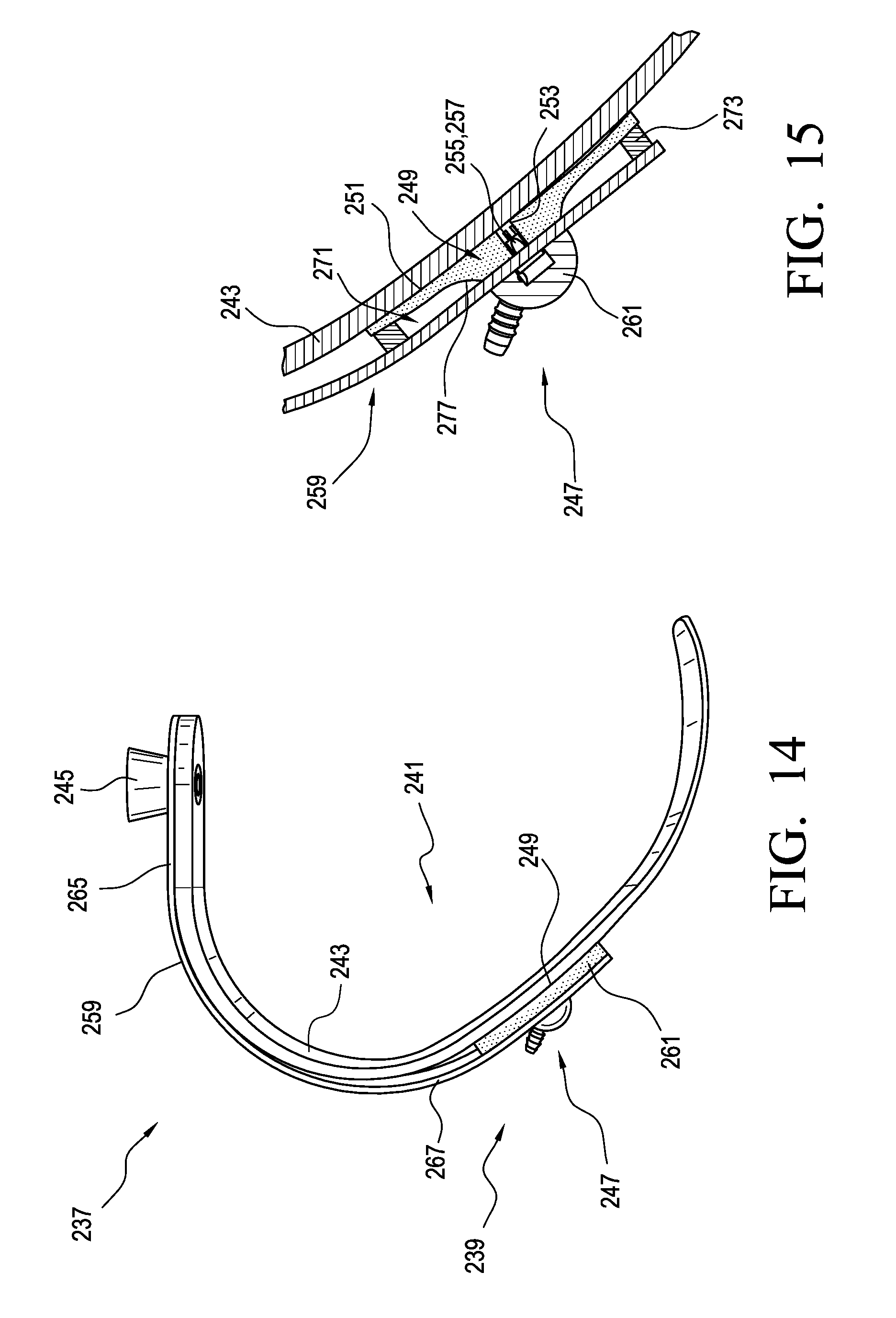
FIG. 14 shows a prosthetic system according to another embodiment.
FIG. 15 shows a cross section view of the prosthetic system in FIG. 14.
DETAILED DESCRIPTION OF THE DISCLOSURE
It will be understood that, unless a term is expressly defined in this disclosure to possess a described meaning, there is no intent to limit the meaning of such term, either expressly or indirectly, beyond its plain or ordinary meaning.
Any element in a claim that does not explicitly state "means for" performing a specified function, or "step for" performing a specific function, is not to be interpreted as a "means" or "step" clause as specified in 35 U.S.C. .sctn. 112, paragraph 6.
The embodiments of a prosthetic system will be described which form part of a vacuum system. A vacuum pump system having a fluid connection with a socket assists in creating a vacuum between a residual limb and the socket by pumping fluid out of the socket. The fluid can be pumped out of the socket manually or in swing and/or stance. For instance, pivotal movement about a joint between a socket and a pylon of the prosthetic system can cause a pump mechanism of the present disclosure to increase the volume of a fluid chamber in the pump mechanism. The increase in volume of the pump mechanism draws in fluid from the vacuum space between the residual limb and the socket of a prosthetic system. In this manner, the pump mechanism decreases the air pressure within the vacuum space causing a vacuum effect.
The volume of the fluid chamber in the pump mechanism can also automatically decrease. The connection between the vacuum space and the pump mechanism may have a one-way valve assembly, so all of the air within the volume of the pump mechanism is expelled out of an outlet to another space or to atmosphere. The outlet can be provided with a one-way valve assembly so the vacuum space is the only source of air.
The prosthetic system of the present disclosure advantageously can produce a vacuum effect in a prosthetic socket utilizing a pivoting, swinging, or rotating mechanism at a joint rather than relying primarily on a force or pressure applied to the prosthetic system by the user. The prosthetic system of the present disclosure also produces a vacuum effect that is advantageous over prior art devices that require compression of the pump to expel air before the pump can be decompressed to draw in air. The present disclosure achieves smaller fluctuations in air pressure than the prior art systems, so the difference between the greatest pressure and lowest pressure in the vacuum space of the socket is less.
The pump mechanism embodiments may easily retrofit on existing prosthetic devices and can do so without undesirably affecting their function. They are also lightweight and low-profile, advantageously contributing little to no bulk to a prosthetic foot. Optionally, the pump mechanism embodiments can be located at or near the socket such that there is no need to move fluid drawn into the pump mechanism from the socket down to the prosthetic foot. This advantageously reduces the time required to produce an elevated vacuum in the socket. Further, it eliminates or reduces the need of a long tube extending between the prosthetic foot and the socket, reducing the likelihood of leaks and volume to generate vacuum.
The efficiency of the pump mechanism is determined at least in part by how effectively the volume of the fluid chamber is reduced. Since the pump mechanism begins at and returns to the original state of zero or near-zero volume, the volume of the fluid chamber is determined by the pivoting force applied to the pump, not by a full compression and recompression cycle as in the prior art. In addition, all fluid drawn into the pump mechanism is expelled afterwards, fully utilizing the volume of the fluid chamber.
The vacuum suspension system also reduces volume fluctuations of the residual limb and allows for increased proprioception and reduced pistoning since there is a better attachment between the socket and the residual limb. It may also be beneficial to produce hypobaric pressure below a certain level in the socket. This may be achieved using a sealing membrane or seal component between the residual limb and the socket, instead of the conventional sealing method of using a sleeve to form an airtight connection between the residual limb and the proximal end of the socket. The sealing membrane may be on a prosthetic liner as described in U.S. Pat. Nos. 8,034,120, 8,894,719, and 9,056,022, all incorporated by reference and belonging to the assignee of this disclosure.
The benefit of using a liner having a seal or seal component reduces the volume of air to be drawn out of the socket and therefore, a better suspension may be achieved in a shorter time period. Using a silicone liner with integrated seal also provides the added benefit that the hypobaric region is not directly applied to the skin.
The vacuum pump mechanisms in the embodiments of the prosthetic system described are generally described as a pump system or mechanism and may include any suitable type of pump mechanism. For instance, the pump mechanism may be a pump as described in U.S. Pat. Nos. 9,072,617, 9,044,348, 9,486,335, and 9,615,946 and U.S. patent application Ser. Nos. 14/747,788 and 15/457,266, all incorporated by reference and belonging to the assignee of this disclosure. A piston-type pump may be used in the embodiments in place of a membrane-type pump. A bladder-type pump may also be used in the embodiments in place of a membrane-type pump, and a skilled person would understand that the pump mechanisms described may also be used with a bladder-type pump and vice versa.
A bladder-type pump has an interior fluid chamber surrounded by an airtight material. When the interior chamber is expanded, the opposing walls are moved away from each other by extending at least one side wall of the pump. The side walls of the bladder-type pump may have an accordion-like shape or be formed of a polymeric material which allow for the increase in distance between the opposing walls.
A membrane-type pump has at least one wall of flexible material and a second opposing wall which may be rigid or flexible. The edges of the two walls are attached to each other such that when a force applies to the pump to expand the interior fluid chamber, the force deforms at least the flexible wall, and the flexible wall arcs outward to form an interior fluid chamber. To allow for deformation, the flexible wall may be made of a polymeric material including elastomeric material such as rubber or plastic.
The bladder-type pump and membrane-type pump are arranged so that the initial volume of the interior fluid chamber is zero or near-zero. The pumps described and shown have a cylindrical shape. A skilled person would understand that the pumps may have a variety of shapes, for example, a diamond, rectangular, or triangular shape.
The specific embodiments of the prosthetic device will now be described regarding the figures.
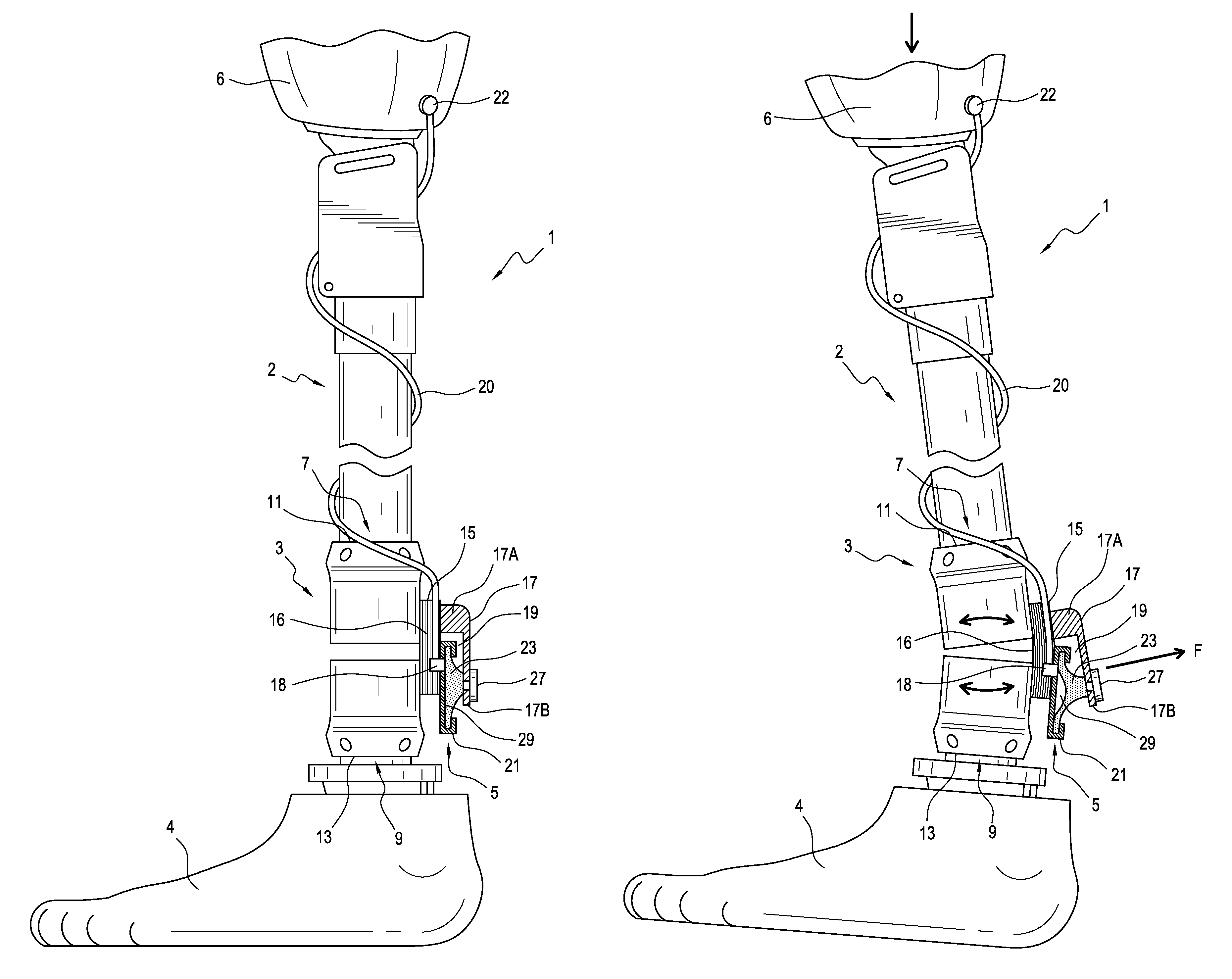
FIGS. 1A and 1B show a prosthetic system 1 including a pump system 3. As seen in FIG. 1A, the pump system 3 comprises a prosthetic connector having a pump mechanism 5, an upper section 7, and a lower section 9. The prosthetic connector is arranged to form at least part of a weight bearing connection 2 between a prosthetic foot 4 and a socket 6 as shown. A tube 20 and valve 22 can connect the pump mechanism 5 to the socket 6.
At least one of the upper and lower sections 7, 9 is arranged to rotate or move relative to the other. In an embodiment, the upper section 7 includes an attachment adaptor 11 and the lower section 9 includes an attachment adaptor 13. The adaptors 11, 13 are shown as female adaptors but can be male adaptors or any other suitable attachment adaptors.
A support member 15 connects the upper section 7 and the lower section 9. The support member 15 has load-carrying configuration and defines a joint 16 about which at least one of the upper and lower sections 7, 9 pivots relative to the other. When no load is placed on the prosthetic system 1, the support member 15 maintains its shape and supports the upper section 7 and the lower section 9 a distance from one another. When a load is placed on the prosthetic system 1, the support member 15 flexes or bends, which, in turn, pivots the upper and lower sections 7, 9 relative to one another about the joint 16. The joint 16 can be located anywhere along the length of the support member 15. The support member 15 can be made of polymer material, carbon fiber, metal, combinations thereof, or any other suitable material.
The pump mechanism 5 is positioned in a receiving space 19 defined between the support member 15 and the movable member 17. The pump mechanism 5 includes a housing 21 attached to the support member 15 and a membrane 23 operatively connected to a movable member 17. The pump mechanism 5 may include at least one valve assembly 18 arranged to control movement of fluid into and from the pump mechanism 5.
The pump mechanism 5 relies upon deformation of the membrane 23 to move between an original configuration (shown in FIG. 1A) in which the volume of a fluid chamber 29 defined between the membrane 23 and the housing 21 is zero or near-zero, and an expanded configuration (shown in FIG. 1B) in which the volume of the fluid chamber 29 is increased.
When a force F is exerted on the membrane 23 in a direction away from the housing 21, the pump mechanism 5 moves toward the expanded configuration (shown in FIG. 1B) as the force pulls the center portion of the membrane 23 away from the housing 21, causing deformation of the membrane 23 and an increase in volume of the fluid chamber 29. This increase in volume of the fluid chamber 29 can draw fluid into the fluid chamber 29 from the socket 6 through at least one valve assembly 18. The housing 21 may be formed of metal such as stainless steel, carbon fiber, or plastic or any other material which would provide sufficient strength to resist deformation when pulled away from the membrane 23.
Once the force F is removed from the membrane 23, the pump mechanism 5 returns toward its original configuration (shown in FIG. 1A) as the membrane 23 returns toward the housing 21 and fluid within the fluid chamber 29 is expelled out of the at least one valve assembly. The membrane 23 can be elastomeric and can use at least in part its material properties to naturally or elastically return to its original position on the housing 21.
The membrane 23 may have any desired shape but is shown having a generally elliptical or circular shape. The membrane 23 can be attached at or near its center point to the movable member 17 via a connector 27 while the outer radial edge portion of the membrane 23 is attached to the housing 21. When the membrane 23 is pulled away from the housing 21, a pocket forms in the middle area of the membrane 23 due to the deformation of the membrane 23. The formation of the pocket increases the volume of the fluid chamber 29. The pump mechanism 5 thus uses a compliant membrane to create suction. The connecter 27 can be an insert formed of metal, plastic, or any other suitable material. In other embodiments, the connector 27 may be formed of a material that is part of the membrane 23.
The movable member 17 has a rigid configuration and is connected to the support member 15. The movable member 17 can include a base part 17A and an elongated part 17B. The base part 17A can be attached to a proximal portion of the support member 15 and extends a distance outwardly therefrom. The elongated part 17B extends generally downward from the base part 17A and is connected to the membrane 23 via the connector 27.
The movable member 17 can define an opening or slot for receiving the connector 27. To attach the movable member 17 to the membrane 23, a shaft portion of the connector 27 can be received in the opening or slot such that the elongated part 17B of the movable member 17 is connected to the connector 27. The connector 27 can be attached to the movable member 17 via a pin, nut, flange, removable head portion, or other fastener. Through the structure of the connector 27 and the movable member 17, the pump mechanism 5 has the benefit of being easily and quickly removed and/or replaced from prosthetic system 1.
During weight bearing or when a load is applied to the prosthetic system 1, the support member 15 flexes or bends, which, in turn, causes the upper section 7 and the base part 17A of the movable member 17 to pivot or rotate about the joint 16 and toward the lower section 9 as seen in FIG. 1A.
When the base part 17A rotates about the joint 16 toward the lower section 9, the elongated part 17B of the movable member 17 rotates away from the support member 15, which, in turn, causes the connector 27 to pull the membrane 23 away from the housing 21, increasing the volume of the fluid chamber 29. This increase in volume of the fluid chamber 29 creates a vacuum in the pump mechanism 5, pulling fluid into the pump mechanism 5. Pivoting movement between the upper and lower sections 7, 9 thus automatically creates a vacuum in the pump mechanism 5.
After weight bearing or when the load is removed, stored energy in the support member 15 forces the upper and lower sections 9, 11 to rotate away from one another. This moves the elongated part 17B of the movable member 17 back toward the housing 21, moving the membrane 23 toward the housing 21 and expelling fluid within the fluid chamber 29 out of the pump mechanism 5. As such, the support member 15 can both move the pump mechanism 5 toward the expanded configuration when loaded, and bias the pump mechanism 5 from the expanded configuration toward the original configuration when unloaded.
The pump system 3 can thus generate a vacuum in a socket using a pivoting or swinging movement between the upper and lower sections 9, 11 without undesirably affecting the functionality of a prosthetic foot associated with the system or significantly increasing the bulk of the prosthetic system 1.
The pump system 3 is shown being located closer to the foot 4 than the socket 6 but it will be appreciated that the pump system 3 can be located at any suitable position within the system 1. For instance, the pump system 3 can be located nearer to the socket 6 such that there is no need to move fluid drawn into the pump mechanism from the socket 6 down to the prosthetic foot 4. This advantageously reduces the time required to produce an elevated vacuum in the socket. Further, it eliminates or reduces the need of a long tube extending between the prosthetic foot and the socket, reducing the likelihood of leaks and volume to generate vacuum.
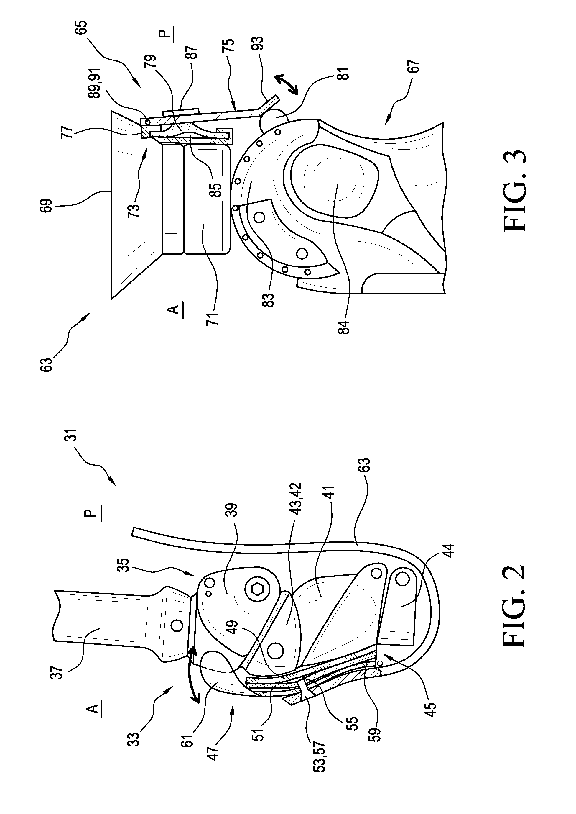
FIG. 2 illustrates a prosthetic system 31 including a pump system 33 according to another embodiment. The system 31 includes a prosthetic knee 35 and a pylon 37 connected to the prosthetic knee 35. The prosthetic knee 35 can be any suitable prosthetic knee and is arranged to form at least part of a weight bearing connection between a prosthetic foot and a socket.
In order to better understand the operation of the system 31, a basic discussion of the gait cycle is provided. A gait cycle defines the movement of the leg between successive heel contacts of the same foot. The gait cycle has two phases: stance and swing. The stance phase has three time periods: heel-strike, mid-stance and toe-off. During mid-stance, the knee joint will be at full extension. Maximum flexion of the knee joint, while walking, will occur at the end of the toe-off phase. Immediately following the end of the toe-off phase begins the swing phase.
While the stance phase has three time periods, the swing phase has two time periods: acceleration and deceleration. The acceleration phase begins immediately following the maximum flexion during the toe-off phase. During the acceleration phase, the lower portion of the leg, comprising the shin and foot, swings back towards full extension. In a natural knee joint, a deceleration phase follows the acceleration phase, during which the lower portion of the leg continues to swing towards full extension.
The knee 35 includes a proximal part 39, a distal part 41, and a link 43 connecting the proximal part 39 and the distal part 41. According to a variation, the link 43 can comprise a load-dependent brake system 43 arranged to selectively prevent rotation of the proximal part 39 relative to the distal part 41 when the knee 35 is loaded by a user in stance. When the load on the knee 35 is removed or reduced, the load-dependent brake system can be released and the knee 35 can swing or the proximal part 39 can rotate relative to the distal part 41 about a joint 42 defined by the link 43. The pylon 27 can be attached to an attachment adaptor positioned at the top of the proximal part 39 and a distal tube clamp attachment 44.
The pump system 33 includes a pump mechanism 45 and a movable member 47. The pump mechanism 45 includes a housing 49, a membrane 51, and at least one valve assembly 53 arranged to control movement of fluid into and from the pump mechanism 45. The housing 49 comprises a base plate attached to the anterior portion of the distal part 41.
The pump mechanism 45 relies upon deformation of the membrane 51 to move between an original configuration in which the volume of a fluid chamber 55 defined between the membrane 51 and the housing 49 is zero or near-zero, and an expanded configuration (shown in FIG. 2) in which the volume of the fluid chamber 55 is increased. The membrane 51 may have any desired shape.
The membrane 49 can be attached at or near its center point to the movable member 47 via a connector 57 while the outer radial edge portion of the membrane 51 can be attached to the housing 49. When the membrane 51 is pulled away from the housing 49, a pocket forms in the middle area of the membrane 51 due to the deformation of the membrane 51. The formation of the pocket increases the volume of the fluid chamber 55, creating suction. The connector 57 can be made of any suitable material. In an embodiment, the connector 57 can define a through channel in fluid communication with the fluid chamber 55 and the at least one valve assembly 53.
The movable member 47 has a rigid configuration and is located on the anterior portion of the knee 35 and spans the proximal part 39 and the distal part 41. The movable member 47 can define an opening or slot for receiving the connector 57. Through the structure of the connector 57 and the movable member 47, the pump system 33 has the benefit of being easily and quickly removed and/or replaced from the system 31. The movable member 47 includes a distal end portion 59 arranged to engage the distal part 41 of the knee 35 and a proximal end portion 61 arranged to engage the distal part 39 of the knee 35. The distal end portion 59 of the movable member 47 can be pivotally connected to the knee 35 at or near a distal region thereof.
At extension of the knee 35, the proximal end portion 61 engages the proximal part 39 as the proximal part 39 rotates in a counterclockwise direction about the joint 42. This pushes the movable member 47 away from the housing 49 and causes the connector 57 to pull the membrane 51 away from the housing 49, increasing the volume of the fluid chamber 55. This increase in volume of the fluid chamber 55 creates a vacuum in the pump mechanism 45, pulling fluid into the pump mechanism 45 through a tube 63 attached to the socket.
During flexion of the knee 35, the proximal end portion 61 disengages the proximal part 39 as the proximal part 39 rotate about the joint 42 to decrease the angle therebetween, which, in turn, allows the pump mechanism 45 to return toward its original configuration. As the membrane 51 returns toward the housing 49, fluid within the fluid chamber 55 is expelled out of the at least one valve assembly 53. As noted above, the membrane 51 can be elastomeric and can use at least in part its material properties to naturally or elastically return to its original position on the housing 49. Optionally, the pump mechanism 45 can include a closure-assist mechanism arranged to bias or move the pump mechanism 45 toward its original configuration and/or maintain it therein.
The pump system 33 can thus generate a vacuum using the swinging or pivoting movement of the knee 35 without undesirably affecting the functionality of the knee or significantly increasing the bulk of the prosthetic system 31. In addition, the pump mechanism 45 can be located nearer to the socket such that there is no need to move fluid drawn into the pump mechanism from the socket down to a prosthetic foot. This advantageously reduces the time required to produce an elevated vacuum in the socket. Further, it eliminates or reduces the need of a longer tube extending between the prosthetic foot and the socket, reducing the likelihood of leaks and volume to generate vacuum. While the pump system is shown positioned on the anterior of the knee, it will be appreciated that the pump system can be positioned at any suitable position on a knee.
FIG. 3 illustrates yet another embodiment of a pump system located on a posterior aspect of a prosthetic knee. As shown, a prosthetic system 63 including a pump system 65 is positioned on a posterior aspect P of a prosthetic knee 67. The system 63 includes a socket assembly 69 arranged to embrace a residual limb and the prosthetic knee 67 connected to the socket assembly 69. The socket assembly 69 can be attached to an attachment adaptor 71 positioned at the top the knee 67. The knee 67 defines a joint 84 and a first part 83 arranged to rotate about the joint 84. The knee 67 is arranged to form at least part of a weight bearing connection between a prosthetic foot and the socket assembly 69.
The pump system 65 includes a pump mechanism 73, a movable member 75, and a protrusion 81 on the first part 83 of the knee 67. The pump mechanism 73 includes a housing 77, a membrane 79, and at least one valve assembly arranged to control movement of fluid into and/or from the pump mechanism 73. The housing 77 is attached to the posterior aspect P of the attachment adaptor 71.
The pump mechanism 73 relies upon deformation of the membrane 79 to move between an original configuration in which the volume of a fluid chamber 85 defined between the membrane 79 and the housing 77 is zero or near-zero, and an expanded configuration (shown in FIG. 3) in which the volume of the fluid chamber 85 is increased. The membrane 79 may have any desired shape.
The membrane 79 can be attached at or near its center point to the movable member 75 while the outer radial edge portion of the membrane 79 can be attached to the housing 77. The membrane 79 can be attached to the movable member 75 via a connecter 87. The connector 87 can be made of any suitable material. In an embodiment, the connector 87 can define a through channel in fluid communication with the fluid chamber 85 and the at least one valve assembly.
The movable member 75 has a rigid configuration and includes a proximal end portion 89 attached to the housing 77 at a first location point 91. In the illustrated embodiment, the movable member 75 can be pivotally attached to the housing 77 at the first location point 91. In other embodiments, the movable member 75 can be arranged to flex or bend at or near the first location point 91. The movable member 75 can be integral to the housing 77.
The movable member 75 includes a distal end portion 93 arranged to selectively engage the protrusion 81 on the first part 83 of the knee 67. The protrusion 81 can have any suitable shape but is shown having a rounded or curved outer surface. The protrusion 81 can be attached to the first part 83 of the knee 67. The protrusion 81 can be integral to the first part 83. The protrusion is arranged to selectively lift the movable member 75 away from the housing 77 by engaging the distal end portion 93 of the movable member 75.
At extension of the knee 67, the protrusion 81 on the first part 83 of the knee 76 engages the distal end portion 93 of the movable member 75 as the first part 83 straightens relative to the socket assembly 69, which, in turn, lifts or rotates the movable member 75 away from the housing 77. This causes the connector 87 to pull the membrane 79 away from the housing 77, increasing the volume of the fluid chamber 85. This increase in volume of the fluid chamber 85 creates a vacuum in the pump mechanism 73.
During flexion of the knee 67, the protrusion 81 disengages the distal end portion 93 of the movable member 75, which, in turn, allows the pump mechanism 73 to return toward its original configuration. As the membrane 79 returns toward the housing 77, fluid within the fluid chamber 85 is expelled out of the pump mechanism 73. According to a variation, the movable member 75 can be arranged to bias the pump mechanism 73 toward its original configuration.
Similar to the previous embodiment, the pump system 65 can thus generate a vacuum using the swinging or pivoting movement of the knee 67 without undesirably affecting the functionality of the knee or significantly increasing the bulk of the prosthetic system 63. In addition, the pump mechanism 73 can be located nearer to the socket assembly 69 such that there is no need to move fluid drawn into the pump mechanism 73 from the socket system 69 down to a prosthetic foot.
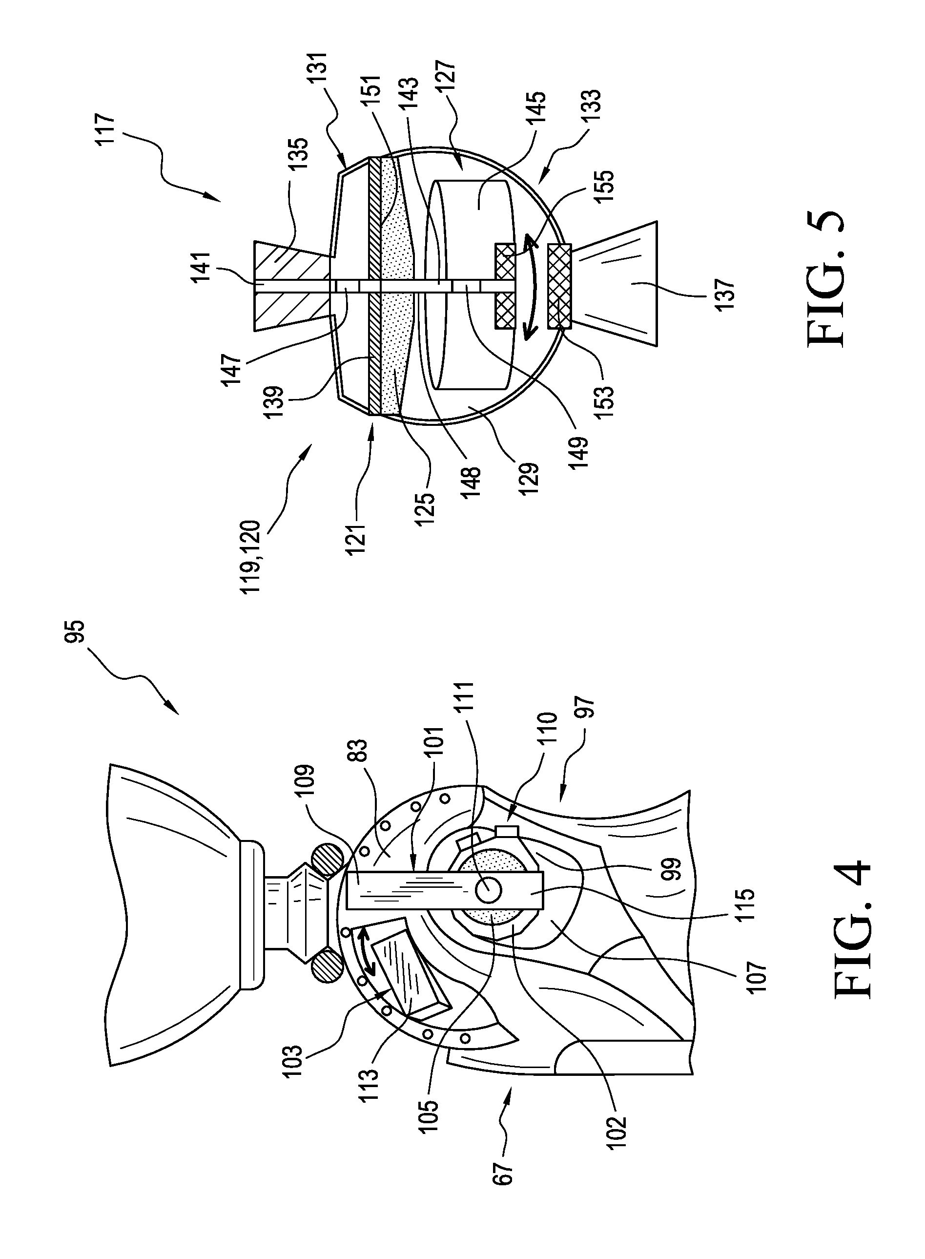
FIG. 4 illustrates a prosthetic system 95 including a pump system 97 according to another embodiment. The prosthetic system 95 is similar in structure and function to the prosthetic system 63 except that the pump system is located on a side of the prosthetic knee. For instance, the pump system 97 includes a pump mechanism 99, a movable member 101, and a protrusion or ramp member 103 on the first part 83 of the knee 67.
The pump mechanism 99 includes a housing 102, a membrane 105, and at least one valve assembly 110 arranged to control movement of fluid into and/or from the pump mechanism 99. The housing 102 is attached to a second part 107 of the knee 67 that is rotatable relative to the first part 83.
Similar to the previously described embodiments, the pump mechanism 99 relies upon deformation of the membrane 105 to move between an original configuration in which the volume of a fluid chamber defined between the membrane 105 and the housing 103 is zero or near-zero, and an expanded configuration in which the volume of the fluid chamber is increased.
The membrane 105 can be attached at or near its center point to the movable member 101 while the outer radial edge portion of the membrane 105 can be attached to the housing 103. The membrane 105 can be attached to the movable member 101 via a connector 111.
The movable member 101 has a rigid or semi-rigid configuration and includes a distal end portion 115 connected to the housing 103. The movable member 101 has an elongate configuration that extends from the distal end portion 115 toward a proximal end portion 109. The movable member 101 can be integral to the housing 103. The movable member 101 can be cantilevered from the housing 101 with the proximal end portion 109 spaced a distance from a side surface of the first part 83.
The proximal end portion 109 is arranged to selectively engage and slide along the protrusion 103 on the first part 83 of the knee 67. The protrusion 103 can have a ramp shape including an inclined contact surface 113 arranged to lift the proximal end portion 109 of the movable member 101 away from the housing 103 as it slides up the protrusion 103.
Upon flexion of the knee 67, the proximal end portion 109 engages and slides up the contact surface 113 of the protrusion 103, which, in turn, lifts or rotates the movable member 101 away from the housing 103. This causes the connector 111 to pull the membrane 99 away from the housing 103, increasing the volume of the fluid chamber.
At extension of the knee 67, the proximal end portion 109 and the protrusion 103 disengage, which, in turn, allows the pump mechanism 99 to return toward its original configuration. As the membrane 105 returns toward the housing 105, fluid within the fluid chamber is expelled out of the at least one valve assembly 107. Optionally, the movable member 101 can be arranged to bias the pump mechanism 99 toward its original configuration. The pump system 97 can thus advantageously generate a vacuum using flexion of the knee 67.
It will be appreciated that locating the pump mechanism 99 where it can be easily reached by a user's hand allows the pump mechanism 99 to be manually activated by the user rather than automatically by the prosthetic knee. For instance, by positioning the pump mechanism 99 on the side of the knee 67 and manipulating the movable member 101, a user can generate and maintain a vacuum pressure in a socket. In other embodiments, embodiments of the pump mechanism can be located on a socket itself and manually operated by a user.
FIG. 5 illustrates a prosthetic system 117 including a pump system 119 according to an embodiment. The pump system 119 comprises a prosthetic connector 120 defining a cavity 129 and including an upper section 131 and a lower section 133. As seen, the upper section 131 can include an attachment adaptor 135 and the lower section 133 can include an attachment adaptor 137. The adaptors 135, 137 are shown as male adaptors but can be female adaptors or any other type of attachment adaptors. It will be appreciated that the prosthetic connector 120 is arranged to form at least part of a weight bearing connection between a prosthetic foot and a socket.
A pump mechanism 121 is located in the cavity 129. The pump mechanism 121 includes a plate member 139, a membrane 125, and a pendulum type mechanism 127. An outer radial edge portion of the membrane 125 can be attached to the plate member 139. A center portion of the membrane 125 can be attached to the pendulum type mechanism 127. For instance, the pendulum type mechanism 127 can comprise a pivoting weighted member 145 suspended from a pivot at or near the center portion of the membrane 125 via an elongated member 148 so that it can swing freely.
A first fluid passageway 141 extends through the upper section 131 and the plate member 139 and a second fluid passageway 143 extends through the membrane 125 and the pendulum type mechanism 127. The pump mechanism 121 can include a first valve assembly 147 positioned in the first passageway 141 that is arranged to control movement of fluid into the pump mechanism 121. A second valve assembly 149 can be positioned in the second fluid passageway 143 to control movement of the fluid out of the pump mechanism 121.
The pump mechanism 121 relies upon deformation of the membrane 125 to move between an original configuration (shown in FIG. 5) in which the volume of a fluid chamber 151 defined between the membrane 125 and the plate member 139 is zero or near-zero, and an expanded configuration in which the volume of the fluid chamber 151 is increased.
In an embodiment, swinging or pivoting movement of the weighted member 145 from a neutral position (shown in FIG. 5) during gait can move the pump mechanism between the original and expanded configurations. For instance, during flexion, the weighted member 145 can swing back and/or forth from the neutral position and the momentum of the weighted member 145 can exert a dynamic tensile force on the membrane 125 to move the pump mechanism between the original and expanded configuration. In other embodiments, the weighted member 145 can swing in unrestricted 360 directions relative to the neutral position. This pulls the membrane 125 away from the plate member 139, increasing the volume of the fluid chamber 151. The increase in volume of the fluid chamber 151 creates a vacuum in the pump mechanism 121, pulling fluid into the pump mechanism 121 through the first valve assembly 147.
At extension, the weighted member 145 can swing back toward the neutral position, which, in turn, allows the pump mechanism 121 to return toward its original configuration. As the membrane 125 returns toward the plate member 139, fluid within the fluid chamber 151 is expelled out of the pump mechanism 121 via the second valve assembly 149.
According to a variation, the pump system 119 can include a closure-assist mechanism arranged to bias the pump mechanism 121 toward the original configuration. For instance, a first magnet 153 can be located on a bottom of the cavity 127 and a corresponding second magnet or ferromagnetic member 155 can be located at the base of the weighted member 145. Magnetic forces between the first and second magnets 153, 155 can function to bring the weighted member 145 back toward the neutral position. While the closure-assist mechanism is described comprising a plurality of magnets, in other embodiments, the closure-assist mechanism can comprise a resilient spring member.
The pump system 119 can thus advantageously draw a vacuum through random or gait motion of the prosthetic system 117, making the pump system 117 more efficient and versatile. Further, the pump system 117 can be placed anywhere near or around the socket or a prosthetic knee.
FIGS. 6-8 show a pump system 157 according to yet another embodiment. The pump system 157 includes a suction cup type pump mechanism. Embodiments of the suction cup type pump mechanism can be adapted to a variety of prosthetic components and to prosthetic feet that are particularly difficult to operate with conventional pump mechanisms, providing versatility.
The pump system 157 comprises a pump mechanism 159 having a suction cup type configuration. The pump mechanism 159 includes an elastomer membrane 161 arranged to be positioned on a sealing surface 163. The sealing surface 163 can comprise an outer surface of a socket, a foot plate, or any other suitable sealing surface. As such, the membrane 161 of the pump mechanism 159 can advantageously be sealed on a variety of prosthetic components and prosthetic feet provided that such components and feet can provide the sealing surface 163.
The membrane 161 is arranged to form a seal with the sealing surface 163. In other words, when there is less pressure in a fluid chamber 167 defined between a bottom of the membrane 161 and the sealing surface 163 than on the outer side of the membrane 161, the pressure differential pushes the membrane 161 down against the sealing surface 163, forcing fluid out and stopping fluid from entering under the edges of the membrane 161 into the fluid chamber 167.
Similar to the other embodiments, the pump mechanism 159 relies upon deformation of the membrane 161 to move between an original configuration in which the volume of the fluid chamber 167 is zero or near-zero, and an expanded configuration in which the volume of the fluid chamber is increased. The membrane 161 can have any suitable shape. For instance, the bottom of the membrane 161 can define a concave curvature.
The membrane 161 defines a passageway 165 in fluid communication with the fluid chamber 167. The passageway 165 can include a fitting 166 arranged to be attached to a tube. According to a variation, a valve assembly can be integrated with the tube or the passageway 165 that is arranged to only allow fluid to enter the fluid chamber 167 via the passageway 165. The valve assembly can comprise a duck-bill valve.
With the membrane 161 sealed on the sealing surface 163, the application of back and forth movement to the membrane 161 can move the pump mechanism 159 between the expanded and original configurations. For instance, when no force is exerted on a center portion of the membrane 161 to expand the fluid chamber 167, the volume of the fluid chamber 167 is zero or near-zero as seen in FIG. 7. When a force F is exerted on the center portion of the membrane 161 to expand the fluid chamber 167, the volume of the fluid chamber 167 is increased, moving the pump mechanism 159 toward the expanded configuration as seen in FIG. 8.
The pump system 157 can thus advantageously create a vacuum using simple and/or random motion to function. The pump system 157 advantageously also does not require a separate mechanism or structure to operate the membrane 161 to create a vacuum in a socket.
According to a variation, as the pump mechanism 159 moves from the expanded configuration toward the original configuration, pressure within the fluid chamber 167 increases until the seal between the membrane 161 and the sealing surface 163 is broken, allowing fluid in the fluid chamber 167 to escape or be expelled out under the sides of the membrane 161. The pump mechanism 159 thus does not require an outlet valve assembly, reducing the overall weight and profile of the pump system 157.
FIG. 9 illustrates a prosthetic system 169 including the pump system 157 according to an embodiment. The prosthetic system 169 includes a socket assembly 171 arranged to receive a residual limb and a prosthetic knee 173 connected to the socket assembly 171. The socket assembly 171 can be attached to an attachment adaptor 175 positioned at the top of the knee 173. The knee 173 includes a proximal part 177 and a distal part 179 attached to the proximal part 177. The proximal part 177 and the socket system 171 are arranged to rotate relative to one another about a joint 181 defined by the knee 173. It will be appreciated that the knee 173 is arranged to form at least part of a weight bearing connection between a prosthetic foot and a socket.
The membrane 161 of the pump mechanism 159 is sealed or placed on a sealing surface 183 defined by an outer surface 185 on the posterior aspect P of the socket assembly 171. A tube 187 connects the pump mechanism 159 to the socket assembly 171 via a valve assembly 188 that is attached to an aperture defined in the socket assembly 171. The tube 187 can be threadedly attached to the threaded fitting 166 of the membrane 161.
A movable member 189 comprising a transfer element operatively connects the pump mechanism 159 to the distal part 179 of the knee 173. The transfer element 189 can be a cable, a lace, a wire or any other suitable member and may refer to a relatively long and relatively thin shaped member and may include a friction reducing coating. The transfer element 189 may be made of any type of material which would provide the transfer element 189 with some rigidity and stiffness including metal, plastic, or fiberglass. The transfer element 189 translates action of the knee 173 to the pump mechanism 159.
According to a variation, the prosthetic system 169 can include a tensioning control mechanism to adjust the length of the transfer element 189. In an embodiment, the transfer element 189 may be placed within a tubular casing. The tubular casing may be made of a variety of materials including plastic or an elastomeric material.
A first end of the transfer element 189 is attached to the pump mechanism 159. The first end of the transfer element 189 can be attached to the threaded fitting 166. From the pump mechanism 159, the transfer element 189 passes through an anchor point 193 on the proximal part 177 of the knee 173 which directs the transfer element 189 downwardly toward the distal part 179 of the knee 173. At the distal part 179 of the knee 173, a second end of the transfer element 189 is attached to the posterior aspect P of the distal part 179.
When the prosthetic system 169 is in flexion, there is slack in the transfer element 189 and the pump mechanism 159 is in its original configuration. As the prosthetic system 169 moves from flexion toward extension, the distal part 179 of the knee 173 rotates about the joint 181 away from the socket system 171. This causes the transfer element 189 to tighten and apply a pulling force on the pump mechanism 159.
The pulling force on the pump mechanism 159 causes the membrane 161 to pull away from the sealing surface 183, moving the pump mechanism 159 to the expanded configuration. More particularly, the transfer element 189 pulls the membrane 161 away from the sealing surface 183 on the socket assembly 171, increasing the volume of the fluid chamber defined between the membrane 161 and the sealing surface 183. This increase in volume of the fluid chamber creates a vacuum in the pump mechanism 159, pulling fluid into the pump mechanism 159 through the tube 187.
As the prosthetic system 169 moves from extension to flexion, the transfer element 189 loosens and the pump mechanism 159 can move back toward its original configuration and decreases the volume of the fluid chamber to zero or near zero. According to a variation, the transfer element 189 has a rigidity and stiffness such that movement from extension to flexion causes the transfer element 189 to slide inside of the tubular casing and exert a pushing force on the membrane 16, pushing the membrane 161 back toward the sealing surface 183.
During the return of the membrane 161 toward the sealing surface 183, the increased pressure in the fluid chamber can break the seal between the membrane 161 and the sealing surface 183, allowing fluid in the fluid chamber to be expelled out under the membrane 161. Because the pump mechanism 159 returns to its original configuration of zero or near-zero volume in the fluid chamber at the beginning or end of each gait cycle, substantially all fluid drawn into the pump mechanism 159 is automatically expelled.
The prosthetic system 169 can thus advantageously use the swinging or pivoting movement between the socket assembly 171 and the distal part 179 of the prosthetic knee 173 to automatically generate a vacuum in the socket assembly 171. In addition, because the pump mechanism 159 is attached directly to the socket assembly 171, the user can easily activate the pump mechanism 159 manually.
FIG. 10 shows yet another embodiment of the pump system 157 implemented with a prosthetic foot. As seen, a prosthetic system 195 can include a prosthetic foot 197 and the pump system 157 secured directly to the foot 197. A tube 198 can fluidly connect the pump system 157 to a prosthetic socket. The membrane 161 of the pump mechanism 159 can be sealed or placed on a sealing surface 199 defined by a proximal surface of the foot 197, providing a sleek and low-profile design.
During gait, the random and/or simple movement between the sealing surface 199 on the foot 197 and the membrane 161 can advantageously create a vacuum in a socket and expel fluid drawn out of the socket to atmosphere while contributing little to no bulk to the foot 197. The pump system 157 can be secured to the foot 197 so that there is a reduced likelihood of the pump system 157 undesirably affecting the functionality of the foot 197, providing a more natural gait.
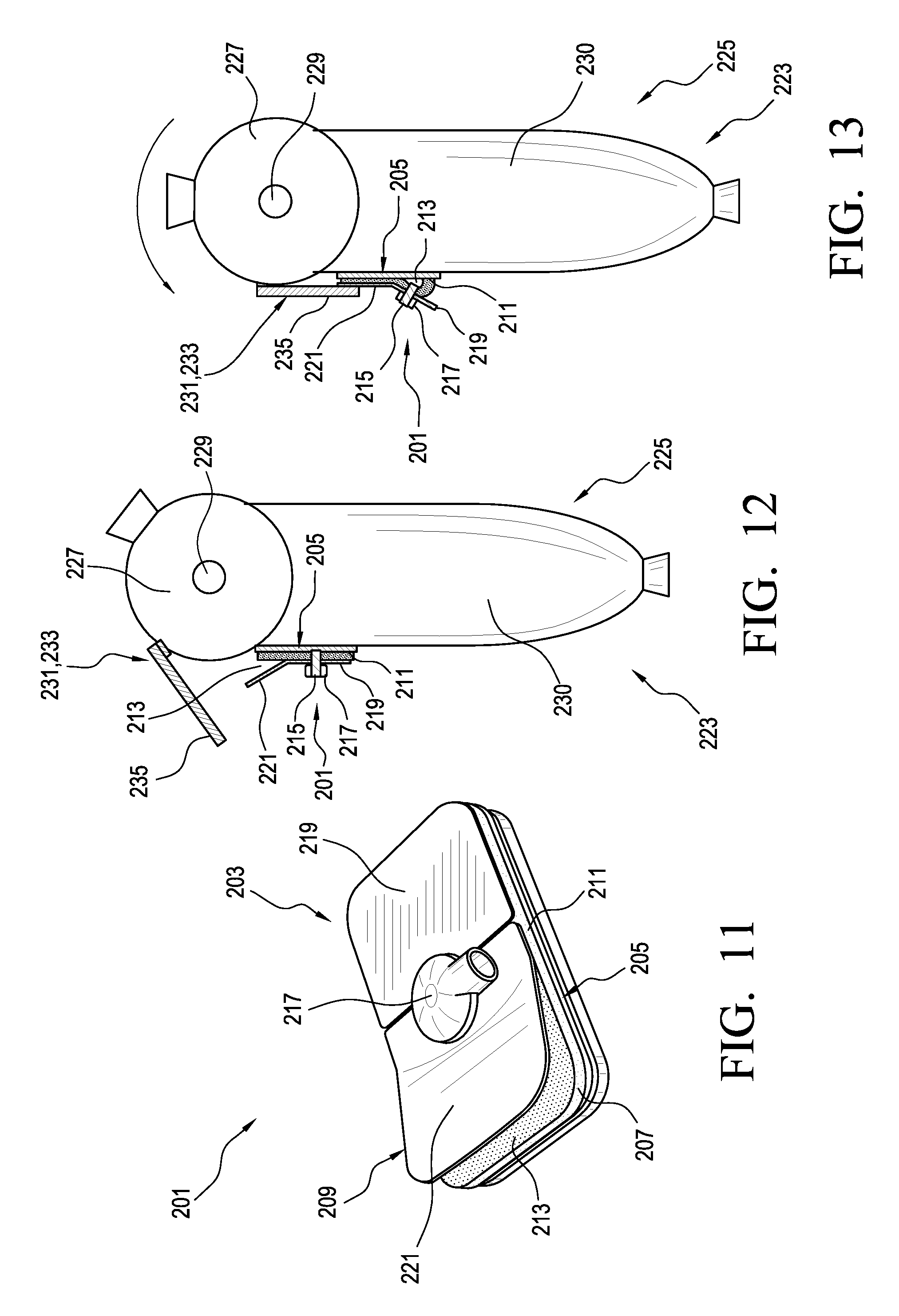
FIGS. 11-13 show another embodiment of a pump system 201 having a suction cup type configuration adaptable to fit a variety of prosthetic components. Additionally, the pump system 201 can use swinging movement at a joint to activate the pump system 201 rather than using the user's weight applied to the prosthetic component.
As seen, the pump system 201 can include a pump mechanism 203 comprising a base plate 205, a membrane 207, and a top plate 209. The membrane 207 defines a bottom arranged to be sealed or placed on a sealing surface 211 defined by the base plate 205.
The pump mechanism 203 relies upon deformation of the membrane 207 to move between an original configuration in which the volume of a fluid chamber 213 (best seen in FIG. 13) defined between the bottom of the membrane 207 and the sealing surface 211 is zero or near-zero, and an expanded configuration in which the volume of the fluid chamber 213 is increased. The membrane 207 can have any suitable shape but is shown having a shape generally corresponding to the base plate 205.
The membrane 207 defines a passageway 215 in fluid communication with the fluid chamber 213. The pump mechanism 203 can include a fitting 217 in fluid communication with the passageway 215 and arranged to be attached to a tube. Optionally, a valve assembly can be integrated with the fitting 217 or a tube associated with the fitting 217. The valve assembly can be arranged to only allow fluid to enter the fluid chamber 213 via the passageway 215.
According to a variation, as the pump mechanism 203 moves from the expanded configuration toward the original configuration, pressure within the fluid chamber 213 increases until the seal between the membrane 207 and the sealing surface 211 is broken, allowing fluid in the fluid chamber 213 to escape out under the sides of the membrane 207.
The top plate 209 has an angled configuration including a first part 219 connected to center portion of the top of the membrane 207 and a second part 221 angled relative to the first part 219 and extending toward a free end. A variable clearance 213 is defined between the bottom of the second part 221 and the top of the membrane 207. In other embodiments, the top plate 209 can have a curved configuration, a linear configuration, an angled configuration, or combinations thereof.
The top plate 209 is arranged to move the pump mechanism 203 between the original and expanded configurations by rocking back and forth relative to the base plate 205.
With the first part 219 of the top plate 209 generally parallel to the base plate 205 and the second part 221 angled upwardly from the first part 219, the pump mechanism 203 is in the original configuration (shown in FIG. 11). Rotation of the second part 221 toward the base plate 205 decreases the clearance 213 and rotates the first part 219 away from the base plate 205, which, in turn, pulls a center portion of the membrane 207 away from the sealing surface 211. Pulling the center portion of the membrane 207 away from the sealing surface 211 deforms the membrane 207, moving the pump mechanism 205 toward the expanded configuration.
When the second part 221 rotates away from the base plate 205 (increasing the clearance 213) and the first part 219 rotates toward the base plate 205, the pump mechanism 203 returns toward its original configuration (shown in FIG. 11) as the membrane 207 returns toward the sealing surface 211. The membrane 207 can use at least in part its material properties to naturally or elastically return to its original position on the sealing surface 211.
FIGS. 12 and 13 illustrates a prosthetic system 223 including the pump system 201 according to an embodiment. As seen, the pump system 201 is attached to an anterior aspect of a prosthetic knee 225. The knee 225 includes a proximal part 227 and a distal part 229 attached to the proximal part 227. The proximal part 227 and the distal part 229 are arranged to relative to one another about a joint 230 defined by the knee 225. It will be appreciated that the knee 225 is arranged to form at least part of a weight bearing connection between a prosthetic foot and a socket.
A movable member 231 comprising an arm 233 is attached to the proximal part 227 of the knee 225. The arm 233 has an elongate configuration and extends generally downward from the outer surface of the proximal part 227. The arm 233 defines a distal portion 235 arranged to selectively engage the second part 221 of the top plate. The arm 233 may be made of any type of material which would provide the arm 233 with rigidity and stiffness including metal, plastic, carbon fiber, or the like. The arm 233 translates swinging or pivoting action of the knee 225 to the pump mechanism 203.
When the knee 225 is in flexion, the distal portion 235 of the arm 233 is separated or spaced a distance from the second part 221 of the top plate 209 and the pump mechanism 203 is in its original configuration as seen in FIG. 12.
As the knee 225 moves from flexion toward extension as seen in FIG. 13, the distal portion 235 of the arm 233 engages and applies direct pressure or force on the second part 221 of the top plate 209 of the pump mechanism 205. The applied pressure or force causes the second part 221 of the top plate 209 to rotate toward the base plate 205 and the first part 219 of the top plate 209 to rotate away from the base plate 205, moving the pump mechanism 203 to the expanded configuration. In an embodiment, the first part 219 of the top plate 209 pulls a center portion of the membrane 207 away from the sealing surface 211, increasing the volume of the fluid chamber 213. This increase in volume of the fluid chamber 213 creates a vacuum in the pump mechanism 205, pulling fluid into the fluid chamber 213 through the passageway 215.
As the knee 225 moves from extension and flexion, the distal portion 235 of the arm 233 disengages from the first part 219 of the top plate 209 and the pump mechanism 203 can move back toward its original configuration. During the return of the membrane 207 toward the sealing surface 211, the increased pressure in the fluid chamber 213 can break the seal between the membrane 207 and the sealing surface 211, allowing fluid in the fluid chamber 213 to be expelled out under the membrane 207. Because of the pump mechanism 203 returns to its original configuration of zero or near-zero volume in the fluid chamber at the beginning or end of each gait cycle, substantially all fluid drawn into the pump mechanism 203 is automatically expelled.
The prosthetic system 223 can thus beneficially use the swinging or pivoting movement of the knee 225 to automatically generate a vacuum in a socket or socket assembly. The pump mechanism 203 is located near the socket such that there is no need to move fluid drawn into the pump mechanism 203 from the socket to a prosthetic foot. This beneficially reduces the time required to produce an elevated vacuum in the socket. It also eliminates or reduces the need of a long tube extending between the prosthetic foot and the socket, reducing the likelihood of leaks and volume to generate vacuum.
FIGS. 14 and 15 illustrate yet another embodiment of a prosthetic system 237 including a pump system 239. As noted above, embodiments of the pump system can be adapted to fit prosthetic feet that are particularly difficult to operate with a conventional pump mechanism.
For instance, the prosthetic system 237 can include a prosthetic sport foot 241 arranged to efficiently store and release energy produced during running to improve performance. The prosthetic running foot 241 has a plate-like member 243 having an overall curved profile. A proximal portion of the plate-like member 243 can have an attachment adaptor 245 for connecting the prosthetic foot to a user's residual limb or to another prosthetic component (e.g., pylon, socket). The prosthetic running foot 241 can be a monolithic member made of a fiber material (e.g., carbon fiber). In other embodiments, the prosthetic running foot 241 can be modular and/or made of other suitable materials. The prosthetic running foot 241 shown is Ossur Cheetah, however, it will be understood that the pump systems described herein can also be adapted for use with other prosthetic running feet and components.
The pump system 239 comprises a pump mechanism 247 having a suction cup type configuration. The pump mechanism 247 includes an elastomer membrane 249 arranged to be positioned on and form seal with a sealing surface 251 defined along a posterior aspect of the plate-like member 243. The membrane 249 has a compliant configuration.
The pump mechanism 247 relies upon deformation of the membrane 249 to move been an original configuration in which the volume of a fluid chamber 253 defined between the sealing surface 251 and a bottom of the membrane 249 is zero or near-zero, and an expanded configuration in which the volume of the fluid chamber 253 is increased. The membrane 249 can have any suitable configuration.
The membrane 249 defines a passageway 255 in fluid communication with the fluid chamber 253. In the illustrated embodiment, a fluid regulator or valve assembly 257 can be associated with the passageway 255. The valve assembly 257 is arranged to only allow fluid to enter the fluid chamber 253 via the passageway 255. The valve assembly 257 can comprise any suitable valve assembly. A housing 261 or fitting can be associated with the passageway 255. The housing 261 can be arranged to attach the pump mechanism 247 to a tube in fluid communication with a socket. The housing 261 can connect the membrane 249 to a support member described below.
As the pump mechanism 247 moves toward the original configuration, pressure within the fluid chamber 253 can increase until the seal between the membrane 249 and the sealing surface 251 is broken, allowing fluid in the fluid chamber 253 to escape or be expelled out under the sides of the membrane 249. The pump mechanism 247 thus does not require an outlet valve assembly, reducing the overall weight and profile of the pump system 239.
A support member 259 is arranged to move the pump mechanism 247 between the original and expanded configurations. The support member 259 can have a rigid configuration. The support member 259 can have any suitable shape but is shown having a curvature generally corresponding to the curvature of the plate-like member 243.
The support member 259 can be attached to a posterior side of the plate-like member 243. A proximal end portion 265 of the support member 259 is attached to the proximal end of the plate-like member 243. A distal end portion 267 of the support member 259 is attached to a center portion of the membrane 249. The support member 259 can define an opening or slot for connecting the membrane 249 to the support member 259.
During stance, the plate-like member 243 compresses and moves away from the distal end portion 267 of the support member 259, which, in turn, causes the support member 259 to pull the center portion of the membrane 249 away from the sealing surface 251, increasing the volume of the fluid chamber 253. This increase in volume of the fluid chamber 253 creates a vacuum in the pump mechanism 247, pulling fluid into the pump mechanism.
In swing or when the load is removed from the foot 247, stored energy in the plate-like member 243 expands the plate-like member 243 and moves it toward the distal end portion 267 of the support member 259, bringing the sealing surface 251 and the center portion of the membrane 249 together. During the return of the sealing surface 251 toward the center portion of the membrane 259, increased pressure in the fluid chamber 253 can break the seal between the membrane 259 and the sealing surface 251, allowing fluid in the fluid chamber 253 to be expelled out under the membrane 249.
The pump system can thus generate a vacuum in a socket using compression and expansion of a sport foot without undesirably affecting the functionality of the foot or significantly increasing the bulk of the running foot.
In addition, because the membrane 249 is compliant, the membrane 249 can create and maintain the seal between the bottom of the membrane 249 and the sealing surface 251 even as the sealing surface 251 moves and changes shape with the expansion and compression of the plate-like member 243. This advantageously allows the pump mechanism 247 to fit on a wider variety of surfaces, feet and prosthetic components.
According to a variation, the pump system 247 includes a closure-assist mechanism 271 arranged to bias the pump mechanism 247 toward the original configuration. In an embodiment, the closure-assist mechanism 271 can comprise a foam member 273 having a resilient configuration positioned between the interior surface of the support member 259 and the outer surface of the membrane 249.
As the pump mechanism 247 moves toward the expanded configuration, the foam member 273 is compressed between the membrane 249 and the support member 259, storing energy in the foam member 273. When the force on the membrane 249 is removed or reduced, the stored energy or resilient properties of the foam member 273 can force the center portion of the membrane 249 back toward the sealing surface 251, biasing the pump mechanism 247 toward the original configuration. Optionally, the center portion of the membrane 249 can be extend through an opening 277 defined in the foam member 263.
While various aspects and embodiments have been disclosed herein, other aspects and embodiments are contemplated. For instance, the membrane used in the embodiments described can vary in thickness in different areas and in shape. The membrane may be a cylindrical shape, a tapered shape, or any other suitable shape. In other embodiments, the pump mechanism can include a plurality of closure-assist mechanisms such as a magnetic closure element and a resilient closure element.
In yet other embodiments, the pump mechanism can be attached to a pylon, prosthetic ankle, or any other suitable prosthetic component. In other embodiments, embodiments of the pump system can include two, three, or any other suitable number of pump mechanisms. In embodiments where the pump system is associated with first and second parts rotatable about a joint, it will be appreciated that the first part may rotate relative to the second part, the second part may rotate relative to the first part, or both parts may rotate about the joint. Further, it will be appreciated that the pump system may be arranged to move the pump mechanism into the expanded configuration in stance, swing, or in both stance and swing.
In other embodiments, the pump mechanism can include one or more features arranged so that a user can regulate or control the level of vacuum generated by the pump mechanism. For instance, the pump mechanism can include a plurality of membranes having different stiffness and/or thickness that can be selected by a user to increase or decrease the volume change of the fluid chamber, which, in turn, controls the vacuum generated by the pump mechanism. In other embodiments, the pump mechanism may include an adjustable closure-assist mechanism that can be manipulated by a user to increase or decrease the level of force required to move the pump mechanism between the expanded and original configurations, which, in turn, controls the vacuum generated by the pump mechanism.
The various aspects and embodiments disclosed herein are for purposes of illustration and are not intended to be limiting. Additionally, the words "including," "having," and variants thereof (e.g., "includes" and "has") as used herein, including the claims, shall be open ended and have the same meaning as the word "comprising" and variants thereof (e.g., "comprise" and "comprises").
* * * * *
References
-
ottobock.com/cps/rde/xbcr/ob_es/646A303-EN-01-1001w.pdf
-
media.ottobock.com/Prosthetics/Socket-Technologies/Harmony/_Genreal/Files/12072403.1_OB-Harmony-UsersGuide-9-10-12.pdf
-
academy.ottobockus.com/videos/harmony/data/downloads/harmony%20course%20manual%202013.pdf
-
-
oandp.org/jpo/library/1995_01_002.asp
D00000
D00001
D00002
D00003
D00004
D00005
D00006
D00007
D00008
XML
uspto.report is an independent third-party trademark research tool that is not affiliated, endorsed, or sponsored by the United States Patent and Trademark Office (USPTO) or any other governmental organization. The information provided by uspto.report is based on publicly available data at the time of writing and is intended for informational purposes only.
While we strive to provide accurate and up-to-date information, we do not guarantee the accuracy, completeness, reliability, or suitability of the information displayed on this site. The use of this site is at your own risk. Any reliance you place on such information is therefore strictly at your own risk.
All official trademark data, including owner information, should be verified by visiting the official USPTO website at www.uspto.gov. This site is not intended to replace professional legal advice and should not be used as a substitute for consulting with a legal professional who is knowledgeable about trademark law.