Selection of managed forwarding element for bridge spanning multiple datacenters
Sharma , et al. Dec
U.S. patent number 10,511,459 [Application Number 15/813,121] was granted by the patent office on 2019-12-17 for selection of managed forwarding element for bridge spanning multiple datacenters. This patent grant is currently assigned to NICIRA, INC.. The grantee listed for this patent is Nicira, Inc.. Invention is credited to Vivek Agarwal, Ganesan Chandrashekhar, Nithin B. Raju, Ankur Kumar Sharma, Xiaohu Wang, Hongwei Zhu.


| United States Patent | 10,511,459 |
| Sharma , et al. | December 17, 2019 |
Selection of managed forwarding element for bridge spanning multiple datacenters
Abstract
Some embodiments provide a method for a set of central controllers that manages forwarding elements operating in a plurality of datacenters. The method receives a configuration for a bridge between (i) a logical L2 network that spans at least two datacenters and (ii) a physical L2 network. The configuration specifies a particular one of the datacenters for implementation of the bridge. The method identifies multiple managed forwarding elements that implement the logical L2 network and are operating in the particular datacenter. The method selects one of the identified managed forwarding elements to implement the bridge. The method distributes bridge configuration data to the selected managed forwarding element.
| Inventors: | Sharma; Ankur Kumar (Mountain View, CA), Wang; Xiaohu (Cupertino, CA), Zhu; Hongwei (Mountain View, CA), Chandrashekhar; Ganesan (Campbell, CA), Agarwal; Vivek (Campbell, CA), Raju; Nithin B. (Sunnyvale, CA) | ||||||||||
|---|---|---|---|---|---|---|---|---|---|---|---|
| Applicant: |
|
||||||||||
| Assignee: | NICIRA, INC. (Palo Alto,
CA) |
||||||||||
| Family ID: | 66432531 | ||||||||||
| Appl. No.: | 15/813,121 | ||||||||||
| Filed: | November 14, 2017 |
Prior Publication Data
| Document Identifier | Publication Date | |
|---|---|---|
| US 20190149358 A1 | May 16, 2019 | |
| Current U.S. Class: | 1/1 |
| Current CPC Class: | H04L 41/0803 (20130101); H04L 41/0893 (20130101); H04L 12/4675 (20130101); H04L 12/4666 (20130101); H04L 12/1854 (20130101); H04L 12/462 (20130101); H04L 61/2596 (20130101); H04L 61/2592 (20130101); H04L 12/1886 (20130101) |
| Current International Class: | H04L 12/46 (20060101); H04L 12/24 (20060101); H04L 12/18 (20060101); H04L 29/12 (20060101) |
References Cited [Referenced By]
U.S. Patent Documents
| 5504921 | April 1996 | Dev et al. |
| 5550816 | August 1996 | Hardwick et al. |
| 5751967 | May 1998 | Raab et al. |
| 6006275 | December 1999 | Picazo, Jr. et al. |
| 6104699 | August 2000 | Holender et al. |
| 6219699 | April 2001 | McCloghrie et al. |
| 6359909 | March 2002 | Ito et al. |
| 6456624 | September 2002 | Eccles et al. |
| 6493767 | December 2002 | Ishida et al. |
| 6512745 | January 2003 | Abe et al. |
| 6539432 | March 2003 | Taguchi et al. |
| 6631137 | October 2003 | Lorrain et al. |
| 6640251 | October 2003 | Wiget et al. |
| 6680934 | January 2004 | Cain |
| 6785843 | August 2004 | McRae et al. |
| 6941487 | September 2005 | Balakrishnan et al. |
| 6950428 | September 2005 | Horst et al. |
| 6963585 | November 2005 | Le Pennec et al. |
| 6999454 | February 2006 | Crump |
| 7046630 | May 2006 | Abe et al. |
| 7197572 | March 2007 | Matters et al. |
| 7200144 | April 2007 | Terrell et al. |
| 7209439 | April 2007 | Rawlins et al. |
| 7215637 | May 2007 | Ferguson et al. |
| 7260648 | August 2007 | Tingley et al. |
| 7283473 | October 2007 | Arndt et al. |
| 7339929 | March 2008 | Zelig et al. |
| 7342916 | March 2008 | Das et al. |
| 7391771 | June 2008 | Orava et al. |
| 7450598 | November 2008 | Chen et al. |
| 7463579 | December 2008 | Lapuh et al. |
| 7478173 | January 2009 | Delco |
| 7555002 | June 2009 | Arndt et al. |
| 7606260 | October 2009 | Oguchi et al. |
| 7643488 | January 2010 | Khanna et al. |
| 7649851 | January 2010 | Takashige et al. |
| 7710874 | May 2010 | Balakrishnan et al. |
| 7760735 | July 2010 | Chen et al. |
| 7764599 | July 2010 | Doi et al. |
| 7792987 | September 2010 | Vohra et al. |
| 7802000 | September 2010 | Huang et al. |
| 7818452 | October 2010 | Matthews et al. |
| 7826482 | November 2010 | Minei et al. |
| 7839847 | November 2010 | Nadeau et al. |
| 7885276 | February 2011 | Lin |
| 7936770 | May 2011 | Frattura et al. |
| 7937438 | May 2011 | Miller et al. |
| 7948986 | May 2011 | Ghosh et al. |
| 7953865 | May 2011 | Miller et al. |
| 7991859 | August 2011 | Miller et al. |
| 7995483 | August 2011 | Bayar et al. |
| 8027354 | September 2011 | Portolani et al. |
| 8031633 | October 2011 | Bueno et al. |
| 8046456 | October 2011 | Miller et al. |
| 8054832 | November 2011 | Shukla et al. |
| 8055789 | November 2011 | Richardson et al. |
| 8060875 | November 2011 | Lambeth |
| 8131852 | March 2012 | Miller et al. |
| 8149737 | April 2012 | Metke et al. |
| 8155028 | April 2012 | Abu-Hamdeh et al. |
| 8166201 | April 2012 | Richardson et al. |
| 8190767 | May 2012 | Maufer et al. |
| 8194674 | June 2012 | Pagel et al. |
| 8199750 | June 2012 | Schultz et al. |
| 8223668 | July 2012 | Allan et al. |
| 8224931 | July 2012 | Brandwine et al. |
| 8224971 | July 2012 | Miller et al. |
| 8239572 | August 2012 | Brandwine et al. |
| 8265075 | September 2012 | Pandey |
| 8281067 | October 2012 | Stolowitz |
| 8312129 | November 2012 | Miller et al. |
| 8320388 | November 2012 | Louati et al. |
| 8339959 | December 2012 | Moisand et al. |
| 8339994 | December 2012 | Gnanasekaran et al. |
| 8351418 | January 2013 | Zhao et al. |
| 8370834 | February 2013 | Edwards et al. |
| 8401024 | March 2013 | Christensen et al. |
| 8456984 | June 2013 | Ranganathan et al. |
| 8504718 | August 2013 | Wang et al. |
| 8565108 | October 2013 | Marshall et al. |
| 8611351 | December 2013 | Gooch et al. |
| 8611352 | December 2013 | Mizrahi et al. |
| 8612627 | December 2013 | Brandwine |
| 8625594 | January 2014 | Safrai et al. |
| 8625603 | January 2014 | Ramakrishnan et al. |
| 8625616 | January 2014 | Vobbilisetty et al. |
| 8627313 | January 2014 | Edwards et al. |
| 8644188 | February 2014 | Brandwine et al. |
| 8660129 | February 2014 | Brendel et al. |
| 8837281 | September 2014 | Sultan et al. |
| 8848508 | September 2014 | Moreno et al. |
| 8856518 | October 2014 | Sridharan et al. |
| 8923155 | December 2014 | Qu et al. |
| 8958298 | February 2015 | Zhang et al. |
| 8989183 | March 2015 | Bansal et al. |
| 9008097 | April 2015 | Bloch et al. |
| 9059999 | June 2015 | Koponen et al. |
| 9137052 | September 2015 | Koponen et al. |
| 9225636 | December 2015 | Krishnan et al. |
| 9246821 | January 2016 | Li et al. |
| 9306837 | April 2016 | Jain et al. |
| 9407450 | August 2016 | Singh et al. |
| 9413644 | August 2016 | Agarwal et al. |
| 9448821 | September 2016 | Wang |
| 9575782 | February 2017 | Chandrashekhar et al. |
| 9768980 | September 2017 | Subramaniyam et al. |
| 9785455 | October 2017 | Chandrashekhar et al. |
| 9893988 | February 2018 | Agarwal et al. |
| 9910686 | March 2018 | Chandrashekhar et al. |
| 9977685 | May 2018 | Chandrashekhar et al. |
| 10020960 | July 2018 | Wang et al. |
| 10225184 | March 2019 | Agarwal et al. |
| 10250443 | April 2019 | Chandrashekhar et al. |
| 2001/0043614 | November 2001 | Viswanadham et al. |
| 2002/0013858 | January 2002 | Anderson |
| 2002/0093952 | July 2002 | Gonda |
| 2002/0194369 | December 2002 | Rawlins et al. |
| 2003/0026258 | February 2003 | Takatani et al. |
| 2003/0026271 | February 2003 | Erb et al. |
| 2003/0041170 | February 2003 | Suzuki |
| 2003/0058850 | March 2003 | Rangarajan et al. |
| 2003/0069972 | April 2003 | Yoshimura et al. |
| 2003/0093481 | May 2003 | Mitchell et al. |
| 2004/0054799 | March 2004 | Meier et al. |
| 2004/0073659 | April 2004 | Rajsic et al. |
| 2004/0098505 | May 2004 | Clemmensen |
| 2004/0267866 | December 2004 | Carollo et al. |
| 2005/0018669 | January 2005 | Arndt et al. |
| 2005/0025179 | February 2005 | McLaggan et al. |
| 2005/0027881 | February 2005 | Figueira et al. |
| 2005/0053079 | March 2005 | Havala |
| 2005/0083953 | April 2005 | May |
| 2005/0120160 | June 2005 | Plouffe et al. |
| 2005/0132044 | June 2005 | Guingo et al. |
| 2005/0182853 | August 2005 | Lewites et al. |
| 2006/0002370 | January 2006 | Rabie et al. |
| 2006/0026225 | February 2006 | Canali et al. |
| 2006/0029056 | February 2006 | Perera et al. |
| 2006/0056412 | March 2006 | Page |
| 2006/0092940 | May 2006 | Ansari et al. |
| 2006/0092976 | May 2006 | Lakshman et al. |
| 2006/0174087 | August 2006 | Hashimoto et al. |
| 2006/0187908 | August 2006 | Shimozono et al. |
| 2006/0193266 | August 2006 | Siddha et al. |
| 2006/0291388 | December 2006 | Amdahl et al. |
| 2007/0008981 | January 2007 | Pathan |
| 2007/0043860 | February 2007 | Pabari |
| 2007/0061492 | March 2007 | van Riel |
| 2007/0064673 | March 2007 | Bhandaru et al. |
| 2007/0097948 | May 2007 | Boyd et al. |
| 2007/0140128 | June 2007 | Klinker et al. |
| 2007/0156919 | July 2007 | Potti et al. |
| 2007/0201357 | August 2007 | Smethurst et al. |
| 2007/0201490 | August 2007 | Mahamuni |
| 2007/0286209 | December 2007 | Wang et al. |
| 2007/0297428 | December 2007 | Bose et al. |
| 2008/0002579 | January 2008 | Lindholm et al. |
| 2008/0002683 | January 2008 | Droux et al. |
| 2008/0008148 | January 2008 | Sagawa |
| 2008/0013474 | January 2008 | Nagarajan et al. |
| 2008/0049621 | February 2008 | McGuire et al. |
| 2008/0049646 | February 2008 | Lu |
| 2008/0059556 | March 2008 | Greenspan et al. |
| 2008/0069107 | March 2008 | Sofia et al. |
| 2008/0071900 | March 2008 | Hecker et al. |
| 2008/0072305 | March 2008 | Casado et al. |
| 2008/0086726 | April 2008 | Griffith et al. |
| 2008/0151893 | June 2008 | Nordmark et al. |
| 2008/0159301 | July 2008 | de Heer |
| 2008/0181243 | July 2008 | Vobbilisetty et al. |
| 2008/0189769 | August 2008 | Casado et al. |
| 2008/0225853 | September 2008 | Melman et al. |
| 2008/0240122 | October 2008 | Richardson et al. |
| 2008/0253366 | October 2008 | Zuk et al. |
| 2008/0291910 | November 2008 | Tadimeti et al. |
| 2008/0298274 | December 2008 | Takashige et al. |
| 2009/0031041 | January 2009 | Clemmensen |
| 2009/0043823 | February 2009 | Iftode et al. |
| 2009/0083445 | March 2009 | Ganga |
| 2009/0092137 | April 2009 | Haigh et al. |
| 2009/0122710 | May 2009 | Bar-Tor et al. |
| 2009/0129271 | May 2009 | Ramankutty et al. |
| 2009/0150521 | June 2009 | Tripathi |
| 2009/0150527 | June 2009 | Tripathi et al. |
| 2009/0161547 | June 2009 | Riddle et al. |
| 2009/0235325 | September 2009 | Dimitrakos et al. |
| 2009/0249470 | October 2009 | Litvin et al. |
| 2009/0249473 | October 2009 | Cohn |
| 2009/0279536 | November 2009 | Unbehagen et al. |
| 2009/0287848 | November 2009 | Kamura et al. |
| 2009/0292858 | November 2009 | Lambeth et al. |
| 2009/0300210 | December 2009 | Ferris |
| 2009/0303880 | December 2009 | Maltz et al. |
| 2010/0046531 | February 2010 | Louati et al. |
| 2010/0107162 | April 2010 | Edwards et al. |
| 2010/0131636 | May 2010 | Suri et al. |
| 2010/0153554 | June 2010 | Anschutz et al. |
| 2010/0153701 | June 2010 | Shenoy et al. |
| 2010/0165877 | July 2010 | Shukla et al. |
| 2010/0169467 | July 2010 | Shukla et al. |
| 2010/0192225 | July 2010 | Ma et al. |
| 2010/0205479 | August 2010 | Akutsu et al. |
| 2010/0208615 | August 2010 | Soon et al. |
| 2010/0214949 | August 2010 | Smith et al. |
| 2010/0257263 | October 2010 | Casado et al. |
| 2010/0275199 | October 2010 | Smith et al. |
| 2010/0287548 | November 2010 | Zhou et al. |
| 2010/0290485 | November 2010 | Martini et al. |
| 2011/0016215 | January 2011 | Wang |
| 2011/0022695 | January 2011 | Dalal et al. |
| 2011/0032830 | February 2011 | Merwe et al. |
| 2011/0035494 | February 2011 | Pandey et al. |
| 2011/0075664 | March 2011 | Lambeth et al. |
| 2011/0075674 | March 2011 | Li et al. |
| 2011/0085557 | April 2011 | Gnanasekaran et al. |
| 2011/0085559 | April 2011 | Chung et al. |
| 2011/0103259 | May 2011 | Aybay et al. |
| 2011/0119748 | May 2011 | Edwards et al. |
| 2011/0134931 | June 2011 | Merwe et al. |
| 2011/0142053 | June 2011 | Merwe Van Der et al. |
| 2011/0194567 | August 2011 | Shen |
| 2011/0202920 | August 2011 | Takase |
| 2011/0205931 | August 2011 | Zhou et al. |
| 2011/0225207 | September 2011 | Subramanian et al. |
| 2011/0261825 | October 2011 | Ichino |
| 2011/0264610 | October 2011 | Armstrong et al. |
| 2011/0283017 | November 2011 | Alkhatib et al. |
| 2011/0299534 | December 2011 | Koganti et al. |
| 2011/0299537 | December 2011 | Saraiya et al. |
| 2011/0310899 | December 2011 | Alkhatib et al. |
| 2011/0317703 | December 2011 | Dunbar et al. |
| 2011/0320577 | December 2011 | Bhat et al. |
| 2012/0008528 | January 2012 | Dunbar et al. |
| 2012/0014386 | January 2012 | Xiong et al. |
| 2012/0014387 | January 2012 | Dunbar et al. |
| 2012/0017022 | January 2012 | Corrigan et al. |
| 2012/0131643 | May 2012 | Cheriton |
| 2012/0158997 | June 2012 | Hsu et al. |
| 2012/0182992 | July 2012 | Cowart et al. |
| 2012/0236734 | September 2012 | Sampath et al. |
| 2012/0307826 | December 2012 | Matsuoka |
| 2012/0323987 | December 2012 | Cantu et al. |
| 2013/0007740 | January 2013 | Kikuchi et al. |
| 2013/0010600 | January 2013 | Jocha et al. |
| 2013/0016723 | January 2013 | Arad et al. |
| 2013/0031233 | January 2013 | Feng et al. |
| 2013/0034094 | February 2013 | Cardona et al. |
| 2013/0044629 | February 2013 | Biswas et al. |
| 2013/0044636 | February 2013 | Koponen et al. |
| 2013/0044641 | February 2013 | Koponen et al. |
| 2013/0054761 | February 2013 | Kempf et al. |
| 2013/0058346 | March 2013 | Sridharan et al. |
| 2013/0073743 | March 2013 | Ramasamy et al. |
| 2013/0097345 | April 2013 | Munoz et al. |
| 2013/0103817 | April 2013 | Koponen et al. |
| 2013/0124750 | May 2013 | Anumala et al. |
| 2013/0125112 | May 2013 | Mittal et al. |
| 2013/0136126 | May 2013 | Wang et al. |
| 2013/0142048 | June 2013 | Gross, IV et al. |
| 2013/0145002 | June 2013 | Kannan et al. |
| 2013/0145008 | June 2013 | Kannan et al. |
| 2013/0148541 | June 2013 | Zhang et al. |
| 2013/0148542 | June 2013 | Zhang et al. |
| 2013/0148543 | June 2013 | Koponen et al. |
| 2013/0148656 | June 2013 | Zhang et al. |
| 2013/0151661 | June 2013 | Koponen et al. |
| 2013/0151676 | June 2013 | Thakkar et al. |
| 2013/0151685 | June 2013 | Bursell |
| 2013/0170490 | July 2013 | Kreeger et al. |
| 2013/0227550 | August 2013 | Weinstein et al. |
| 2013/0227566 | August 2013 | Higuchi et al. |
| 2013/0266015 | October 2013 | Qu et al. |
| 2013/0266019 | October 2013 | Qu et al. |
| 2013/0268588 | October 2013 | Chang et al. |
| 2013/0301553 | November 2013 | Klien |
| 2013/0318219 | November 2013 | Kancherla |
| 2013/0322453 | December 2013 | Allan |
| 2013/0329548 | December 2013 | Nakil et al. |
| 2013/0332602 | December 2013 | Nakil et al. |
| 2013/0332619 | December 2013 | Xie et al. |
| 2013/0332983 | December 2013 | Koorevaar et al. |
| 2013/0339544 | December 2013 | Mithyantha |
| 2014/0006585 | January 2014 | Dunbar et al. |
| 2014/0019639 | January 2014 | Ueno |
| 2014/0025779 | January 2014 | Matsumoto |
| 2014/0036730 | February 2014 | Nellikar et al. |
| 2014/0036924 | February 2014 | Christenson |
| 2014/0050091 | February 2014 | Biswas et al. |
| 2014/0056298 | February 2014 | Vobbilisetty et al. |
| 2014/0064276 | March 2014 | Basso et al. |
| 2014/0068602 | March 2014 | Gember et al. |
| 2014/0092901 | April 2014 | Kapadia et al. |
| 2014/0092907 | April 2014 | Sridhar et al. |
| 2014/0112343 | April 2014 | Lambeth et al. |
| 2014/0115578 | April 2014 | Cooper et al. |
| 2014/0115584 | April 2014 | Mudigonda et al. |
| 2014/0123211 | May 2014 | Wanser et al. |
| 2014/0140244 | May 2014 | Kapadia et al. |
| 2014/0146817 | May 2014 | Zhang |
| 2014/0169169 | June 2014 | Almog et al. |
| 2014/0169215 | June 2014 | Rajendran et al. |
| 2014/0169222 | June 2014 | Cohen et al. |
| 2014/0195666 | July 2014 | Dumitriu et al. |
| 2014/0201733 | July 2014 | Benny et al. |
| 2014/0207930 | July 2014 | Benny |
| 2014/0233567 | August 2014 | Guo et al. |
| 2014/0269705 | September 2014 | Decusatis et al. |
| 2014/0269709 | September 2014 | Benny et al. |
| 2014/0280738 | September 2014 | Kolker et al. |
| 2014/0282889 | September 2014 | Ishaya et al. |
| 2014/0294005 | October 2014 | Jain et al. |
| 2014/0328343 | November 2014 | Kapadia et al. |
| 2014/0334485 | November 2014 | Jain et al. |
| 2014/0337497 | November 2014 | Wanser et al. |
| 2014/0337500 | November 2014 | Lee |
| 2014/0348166 | November 2014 | Yang et al. |
| 2015/0010001 | January 2015 | Duda et al. |
| 2015/0043576 | February 2015 | Dixon et al. |
| 2015/0043581 | February 2015 | Devireddy et al. |
| 2015/0058470 | February 2015 | Duda |
| 2015/0058968 | February 2015 | Wang et al. |
| 2015/0063353 | March 2015 | Kapadia et al. |
| 2015/0100681 | April 2015 | Reese et al. |
| 2015/0103661 | April 2015 | Shen et al. |
| 2015/0103679 | April 2015 | Tessmer et al. |
| 2015/0103839 | April 2015 | Chandrashekhar et al. |
| 2015/0103842 | April 2015 | Chandrashekhar et al. |
| 2015/0103843 | April 2015 | Chandrashekhar et al. |
| 2015/0106804 | April 2015 | Chandrashekhar et al. |
| 2015/0109923 | April 2015 | Hwang |
| 2015/0117454 | April 2015 | Koponen et al. |
| 2015/0124612 | May 2015 | Schlansker et al. |
| 2015/0124817 | May 2015 | Merchant et al. |
| 2015/0124826 | May 2015 | Edsall et al. |
| 2015/0200954 | July 2015 | Gourlay et al. |
| 2015/0281042 | October 2015 | Agarwal et al. |
| 2015/0281048 | October 2015 | Agarwal et al. |
| 2015/0319009 | November 2015 | Zhao |
| 2015/0372943 | December 2015 | Hasan et al. |
| 2016/0021032 | January 2016 | Maier et al. |
| 2016/0057014 | February 2016 | Thakkar et al. |
| 2016/0094364 | March 2016 | Subramaniyam et al. |
| 2016/0094365 | March 2016 | Subramaniyam |
| 2016/0094366 | March 2016 | Wang et al. |
| 2016/0094396 | March 2016 | Chandrashekhar |
| 2016/0218925 | July 2016 | Mammen et al. |
| 2016/0226822 | August 2016 | Zhang et al. |
| 2017/0005918 | January 2017 | Agarwal et al. |
| 2017/0005924 | January 2017 | Agarwal et al. |
| 2017/0005942 | January 2017 | Agarwal et al. |
| 2017/0141962 | May 2017 | Britt et al. |
| 2018/0167316 | June 2018 | Agarwal et al. |
| 2018/0276013 | September 2018 | Chandrashekhar et al. |
| 2019/0149357 | May 2019 | Wang et al. |
| 101808030 | Aug 2010 | CN | |||
| 102571998 | Jul 2012 | CN | |||
| 103491006 | Jan 2014 | CN | |||
| 104025508 | Sep 2014 | CN | |||
| 1653688 | May 2006 | EP | |||
| 2566129 | Mar 2013 | EP | |||
| 2648370 | Oct 2013 | EP | |||
| 2003069609 | Mar 2003 | JP | |||
| 2003124976 | Apr 2003 | JP | |||
| 2003318949 | Nov 2003 | JP | |||
| 2011171874 | Sep 2011 | JP | |||
| 2012231382 | Nov 2012 | JP | |||
| 2013175075 | Sep 2013 | JP | |||
| 2014230217 | Dec 2014 | JP | |||
| 20070050864 | May 2007 | KR | |||
| 2005094008 | Oct 2005 | WO | |||
| 2005112390 | Nov 2005 | WO | |||
| 2008095010 | Aug 2008 | WO | |||
| 2012051884 | Apr 2012 | WO | |||
| 2012093429 | Jul 2012 | WO | |||
| 2013063330 | May 2013 | WO | |||
| 2013074827 | May 2013 | WO | |||
| 2013184846 | Dec 2013 | WO | |||
| 2015054671 | Apr 2015 | WO | |||
| 2015147942 | Oct 2015 | WO | |||
| 2016053372 | Apr 2016 | WO | |||
| 2016053640 | Apr 2016 | WO | |||
| 2017003957 | Jan 2017 | WO | |||
Other References
|
Aggarwal, R., et al., "Data Center Mobility based on E-VPN, BGP/MPLS IP VPN, IP Routing and NHRP," draft-raggarwa-data-center-mobility-05.txt, Jun. 10, 2013, 24 pages, Internet Engineering Task Force, IETF, Geneva, Switzerland. cited by applicant . Caesar, Matthew, et al., "Design and Implementation of a Routing Control Platform," NSDI '05: 2nd Symposium on Networked Systems Design & Implementation , Apr. 2005, 14 pages, Usenix Association. cited by applicant . Casado, Martin, et al., "Virtualizing the Network Forwarding Plane," Dec. 2010, 6 pages. cited by applicant . Dobrescu, Mihai, et al., "RouteBricks: Exploiting Parallelism to Scale Software Routers," SOSP'09, Proceedings of the ACM SIGOPS 22nd Symposium on Operating Systems Principles, Oct. 2009, 17 pages, ACM, New York, NY. cited by applicant . Dumitriu, Dan Mihai, et al. (U.S. Appl. No. 61/514,990), filed Aug. 4, 2011. cited by applicant . Elmeleegy, Khaled, et al., "EtherProxy: Scaling Ethernet by Suppressing Broadcast Traffic," IEEE INFOCOM 2009, Apr. 19, 2009, 9 pages, IEEE. cited by applicant . Himansu, Shah, "ARP Broadcast Reduction for Large Data Centers," draft-shah-armd-arp- reduction-02.txt, Oct. 28, 2011, 11 pages, IETF Trust. cited by applicant . Kamath, Daya, et. al., "Edge Virtual Bridge Proposal," Version 0. Rev. 0.1, Apr. 23, 2010, 72 pages, IEEE. cited by applicant . Koponen, Teemu, et al., "Network Virtualization in Multi-tenant Datacenters," Technical Report TR-2013-001E, Aug. 2013, 22 pages, VMware, Inc., Palo Alto, CA, USA. cited by applicant . Narten, Thomas, et al., "Address Resolution Problems in Large Data Center Networks," Jan. 2013, 17 pages, Internet Engineering Task Force (IETF). cited by applicant . Rosen, E., "Applicability Statement for BGP/MPLS IP Virtual Private Networks (VPNs)," RFC 4365, Feb. 2006, 32 pages, The Internet Society. cited by applicant . Shenker, Scott, et al., "The Future of Networking, and the Past of Protocols," Dec. 2, 2011, 30 pages, USA. cited by applicant . Non-Published Commonly Owned U.S. Appl. No. 15/813,120, filed Nov. 14, 2017, 34 pages, Nicira, Inc. cited by applicant . Nygren, Anders, et al., "OpenFlow Switch Specification v.1.3.4 (Protocol version 0x04)," Mar. 27, 2014, 171 pages, Open Networking Foundation, Palo Alto, USA. cited by applicant . Watsen, Kent, "Conditional Enablement of Configuration Nodes," Feb. 18, 2013, 8 pages, Internet Engineering Task Force Trust, Reston, USA. cited by applicant. |
Primary Examiner: Beharry; Noel R
Assistant Examiner: Zhang; Ruihua
Attorney, Agent or Firm: Adeli LLP
Claims
We claim:
1. For a set of central controllers that manages forwarding elements operating in a plurality of datacenters, a method comprising: receiving a configuration for a bridge between (i) a logical L2 network that spans at least two datacenters and (ii) a physical L2 network, wherein the configuration comprises a tuple that includes a logical network identifier, a physical network identifier, and a datacenter identifier that specifies a particular one of the datacenters for implementation of the bridge; identifying a plurality of managed forwarding elements that implement the logical L2 network and are operating in the particular datacenter; selecting one of the identified managed forwarding elements to implement the bridge; and distributing bridge configuration data to the selected managed forwarding element.
2. The method of claim 1, wherein the configuration is received from a network manager located at the particular datacenter.
3. The method of claim 1, wherein the logical L2 network is a virtual extensible local area network (VXLAN) and the physical L2 network is a virtual local area network (VLAN) located at the particular datacenter.
4. The method of claim 3, wherein machines connected to the VLAN comprise virtual machines operating on host machines that are not VXLAN-compatible.
5. The method of claim 1, wherein the set of central controllers stores a list of managed forwarding elements located at each of the datacenters, wherein each managed forwarding element has an associated datacenter identifier.
6. The method of claim 1, wherein the identified managed forwarding elements operate in virtualization software of host machines located in the particular datacenter, wherein data compute nodes that logically connect to the logical L2 network operate on the host machines.
7. The method of claim 1, wherein the selected managed forwarding element uses the bridge configuration to bridge data packets between the logical L2 network and the physical L2 network.
8. The method of claim 7, wherein the selected managed forwarding element (i) receives a data packet sent by a data compute node connected to the logical L2 network and having a destination address of a data compute node connected to the physical L2 network, (ii) removes a logical network identifier from the packet, and (iii) adds a physical network identifier to the packet.
9. The method of claim 7, wherein the selected managed forwarding element (i) receives a data packet sent by a data compute node connected to the physical L2 network and having a destination address of a data compute node connected to the logical L2 network, (ii) removes a physical network identifier from the packet, and (iii) adds a logical network identifier to the packet.
10. A non-transitory machine readable medium storing a central controller application which when executed by at least one processing unit manages forwarding elements operating in a plurality of datacenter, the central controller application comprising sets of instructions for: receiving a configuration for a bridge between (i) a logical L2 network that spans at least two datacenters and (ii) a physical L2 network, wherein the configuration comprises a tuple that includes a logical network identifier, a physical network identifier, and a datacenter identifier that specifies a particular one of the datacenters for implementation of the bridge; identifying a plurality of managed forwarding elements that implement the logical L2 network and are operating in the particular datacenter; selecting one of the identified managed forwarding elements to implement the bridge; and distributing bridge configuration data to the selected managed forwarding element.
11. The non-transitory machine readable medium of claim 10, wherein the configuration is received from a network manager located at the particular datacenter.
12. The non-transitory machine readable medium of claim 10, wherein the logical L2 network is a virtual extensible local area network (VXLAN) and the physical L2 network is a virtual local area network located at the particular datacenter.
13. The non-transitory machine readable medium of claim 12, wherein machines connected to the VLAN comprise virtual machines operating on host machines that are not VXLAN-compatible.
14. The non-transitory machine readable medium of claim 10, wherein the central controller application stores a list of managed forwarding elements located at each of the datacenters, wherein each managed forwarding element has an associated datacenter identifier.
15. The non-transitory machine readable medium of claim 10, wherein the identified managed forwarding elements operate in virtualization software of host machines located in the particular datacenter, wherein data compute nodes that logically connect to the logical L2 network operate on the host machines.
16. The non-transitory machine readable medium of claim 10, wherein the selected managed forwarding element uses the bridge configuration to bridge data packets between the logical L2 network and the physical L2 network.
17. The non-transitory machine readable medium of claim 16, wherein the selected managed forwarding element (i) receives a data packet sent by a data compute node connected to the logical L2 network and having a destination address of a data compute node connected to the physical L2 network, (ii) removes a logical network identifier from the packet, and (iii) adds a physical network identifier to the packet.
18. The non-transitory machine readable medium of claim 16, wherein the selected managed forwarding element (i) receives a data packet sent by a data compute node connected to the physical L2 network and having a destination address of a data compute node connected to the logical L2 network, (ii) removes a physical network identifier from the packet, and (iii) adds a logical network identifier to the packet.
Description
BACKGROUND
Bridging is a technique used to connect different L2 networks (e.g., different virtual local area networks (VLANs) or logical switches) without routing when the L2 networks share the same subnet. For instance, a bridge could be used to connect workloads (e.g., virtual machines, physical servers) that connect to a VLAN to workloads that connect to a virtual extensible local area network (VXLAN). The use of such bridges is generally constrained to logical networks that are contained within a single datacenter.
BRIEF SUMMARY
Some embodiments provide a method for implementing a bridge between a logical L2 network (e.g., a logical switch) that spans multiple datacenters and a physical L2 network located in one of the datacenters spanned by the logical network. In some embodiments, a network manager located at one of the datacenters receives the configuration for the bridge (e.g., from an administrator) and provides this configuration to a set of central controllers that manages the multiple datacenters, along with a datacenter identifier that specifies the particular datacenter in which the physical L2 network is located. The set of central controllers stores information about the managed forwarding elements at each of the datacenters managed by the central controllers, including datacenter identifiers. Using this data, the set of central controllers selects one of the managed forwarding elements that is located in the same datacenter as the physical L2 network. In addition, some embodiments also require that the selected managed forwarding element operate in a host machine on which a data compute node (e.g., a virtual machine) that connects to the logical network resides.
The set of central controllers receives the bridge configuration as a 3-tuple in some embodiments, that includes (i) a logical network (e.g., VXLAN) identifier, (ii) a physical network (e.g., VLAN) identifier, and (iii) a datacenter identifier. As noted above, each managed forwarding element (which may be, e.g., virtual switches operating in virtualization software of host machines in the datacenters) has an associated datacenter identifier as well. The set of central controllers stores this managed forwarding element data as well as information indicating on which host machine each of the data compute nodes (DCNs) attached to the logical L2 network resides. Using this information, the set of central controllers can select one of the managed forwarding elements that fits both criteria (i.e., operates in a host machine that is located in the datacenter identified in the 3-tuple, and on which one of the logical network DCNs resides).
The set of central controllers distributes the bridge configuration to the selected managed forwarding element, which implements the bridge for packets sent between the logical L2 network and physical L2 network. The managed forwarding element bridges packets by, e.g., removing a logical network identifier from a packet and adding a physical network identifier (e.g., a VLAN tag), or vice versa.
In certain circumstances, the bridge may need to be implemented in multiple datacenters, either moving from one datacenter to another as a failover mechanism or in a configuration in which the bridge operates simultaneously in multiple datacenters at once (e.g., bridging physical L2 networks in multiple datacenters onto the same logical L2 network). Thus, some embodiments use a generic physical network identifier in the bridge configuration that maps to different specific physical L2 networks at different datacenters. The network managers at two different datacenters receive the same configuration specifying a bridge between a logical L2 network that spans the two datacenters and a physical network identifier. The first network manager (at the first datacenter) maps this physical network identifier to a first physical L2 network (e.g., a VLAN) at the first datacenter while the second network manager (at the second datacenter) maps this physical network identifier to a second physical L2 network at the second datacenter. The network managers, in some embodiments, provide the configurations to the set of central controllers using their respective datacenter identifiers and specific physical L2 network identifiers in order for the central controllers to select managed forwarding elements at the two different datacenters to which to provide the respective bridge configurations.
As mentioned, one such circumstance of some embodiments that uses the generic physical network identifier involves moving the bridge from one datacenter to another. In this scenario, the first network manager initially provides the bridge configuration for the first datacenter (i.e., using the first datacenter identifier and an identifier for a specific physical L2 network located at the first datacenter) to the set of controllers, which configures the bridge on a managed forwarding element in the first datacenter. If the first network manager fails (e.g., the machine on which the first network manager operates fails, loses communication, etc.), some embodiments move the bridge to a second datacenter also spanned by the logical L2 network. This second datacenter may have a physical L2 network that acts as a backup for the physical L2 network at the first datacenter. Thus, the second network manager (at the second datacenter) provides the bridge configuration for the second datacenter (using the second datacenter identifier and an identifier for the specific physical L2 network located at the second datacenter) to the set of controllers, which configures the bridge on a managed forwarding element in the second datacenter.
In an active-active scenario, physical L2 networks at more than one datacenter are bridged onto the logical L2 network at the same time. That is, each of the network managers at their respective datacenters maps the generic physical network identifier to their own specific physical L2 network, and provides their separate configuration to the set of central controllers, which configures bridges at each datacenter. Thus, the same traffic from a logical network DCN (e.g., broadcast or multicast traffic) can be bridged onto multiple physical L2 networks at different datacenters.
Having multiple physical L2 networks at different datacenters bridged onto the same logical network can create the possibility of traffic loops as well as undesired connectivity between the physical L2 networks at different datacenters. For instance, a broadcast packet sent from a DCN on the first datacenter's physical L2 network would be bridged onto the logical network by the bridge at the first datacenter, and (because it is a broadcast packet) would reach the bridge at the second datacenter, which would (at least) bridge the packet onto the physical L2 network at the second datacenter. Thus, as the logical network packets are tunneled between host machines (e.g., using VXLAN, GENEVE, STT, etc.), some embodiments use an available field or portion thereof (e.g., a single bit) in the tunnel encapsulation header to identify that a packet has already been bridged. When the managed forwarding element implementing the bridge receives such a packet, the forwarding element does not bridge the packet again, instead just delivering the packet to its destination (e.g., the logical network DCN residing on that host machine).
The preceding Summary is intended to serve as a brief introduction to some embodiments of the invention. It is not meant to be an introduction or overview of all inventive subject matter disclosed in this document. The Detailed Description that follows and the Drawings that are referred to in the Detailed Description will further describe the embodiments described in the Summary as well as other embodiments. Accordingly, to understand all the embodiments described by this document, a full review of the Summary, Detailed Description and the Drawings is needed. Moreover, the claimed subject matters are not to be limited by the illustrative details in the Summary, Detailed Description and the Drawing, but rather are to be defined by the appended claims, because the claimed subject matters can be embodied in other specific forms without departing from the spirit of the subject matters.
BRIEF DESCRIPTION OF THE DRAWINGS
The novel features of the invention are set forth in the appended claims. However, for purpose of explanation, several embodiments of the invention are set forth in the following figures.
FIG. 1 conceptually illustrates a process of some embodiments to select a managed forwarding element to implement a bridge between a logical network that spans multiple datacenters and a physical network at one of the datacenters.
FIG. 2 conceptually illustrates a set of central controllers that receives a bridge configuration, selects a managed forwarding element, and provides the bridge configuration to the selected managed forwarding element.
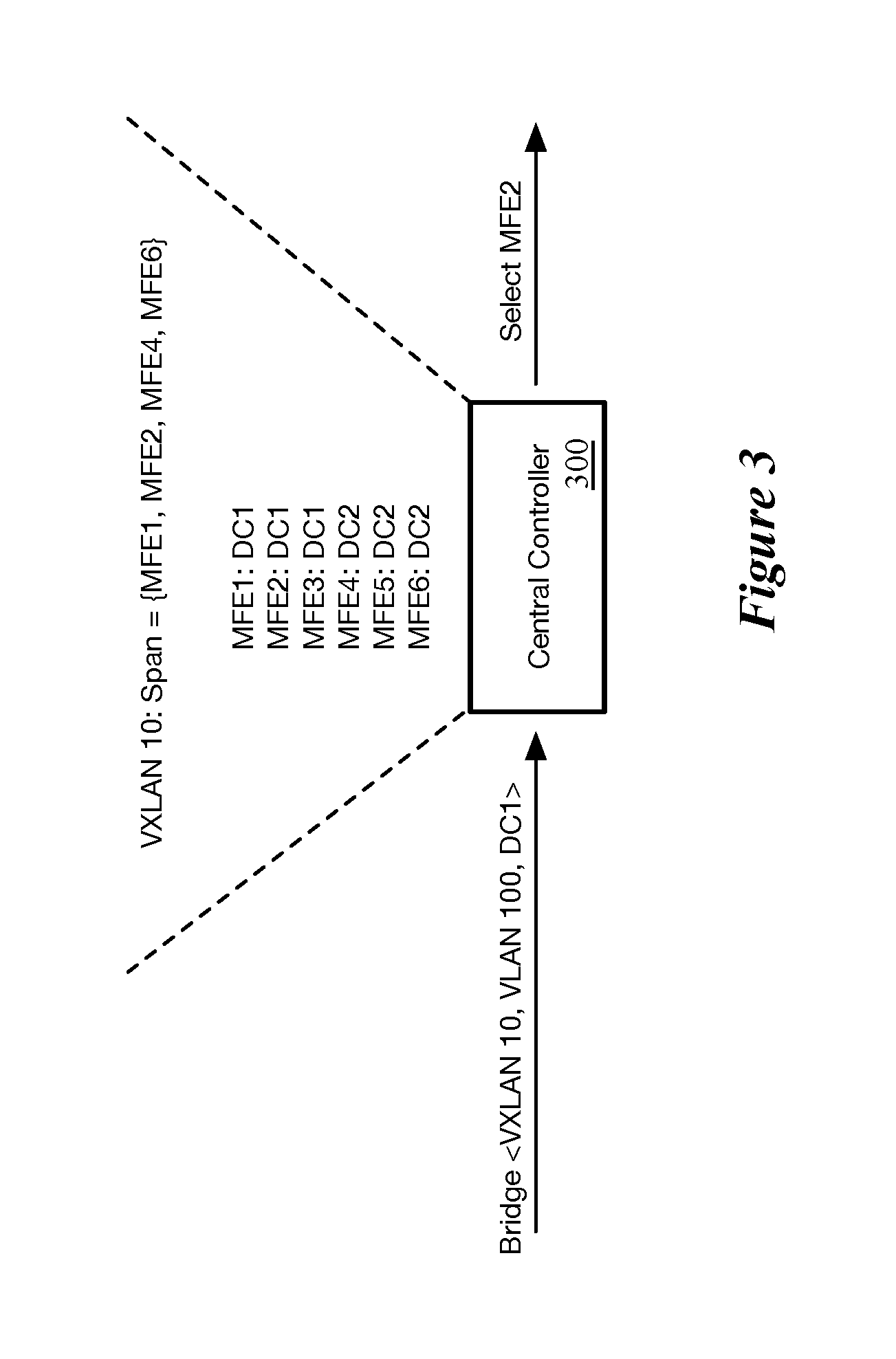
FIG. 3 conceptually illustrates an example of the selection of an MFE for a bridge by a central controller.
FIG. 4 conceptually illustrates an example of an MFE bridging a packet sent from a first DCN on a logical network to a second DCN on a physical L2 network.
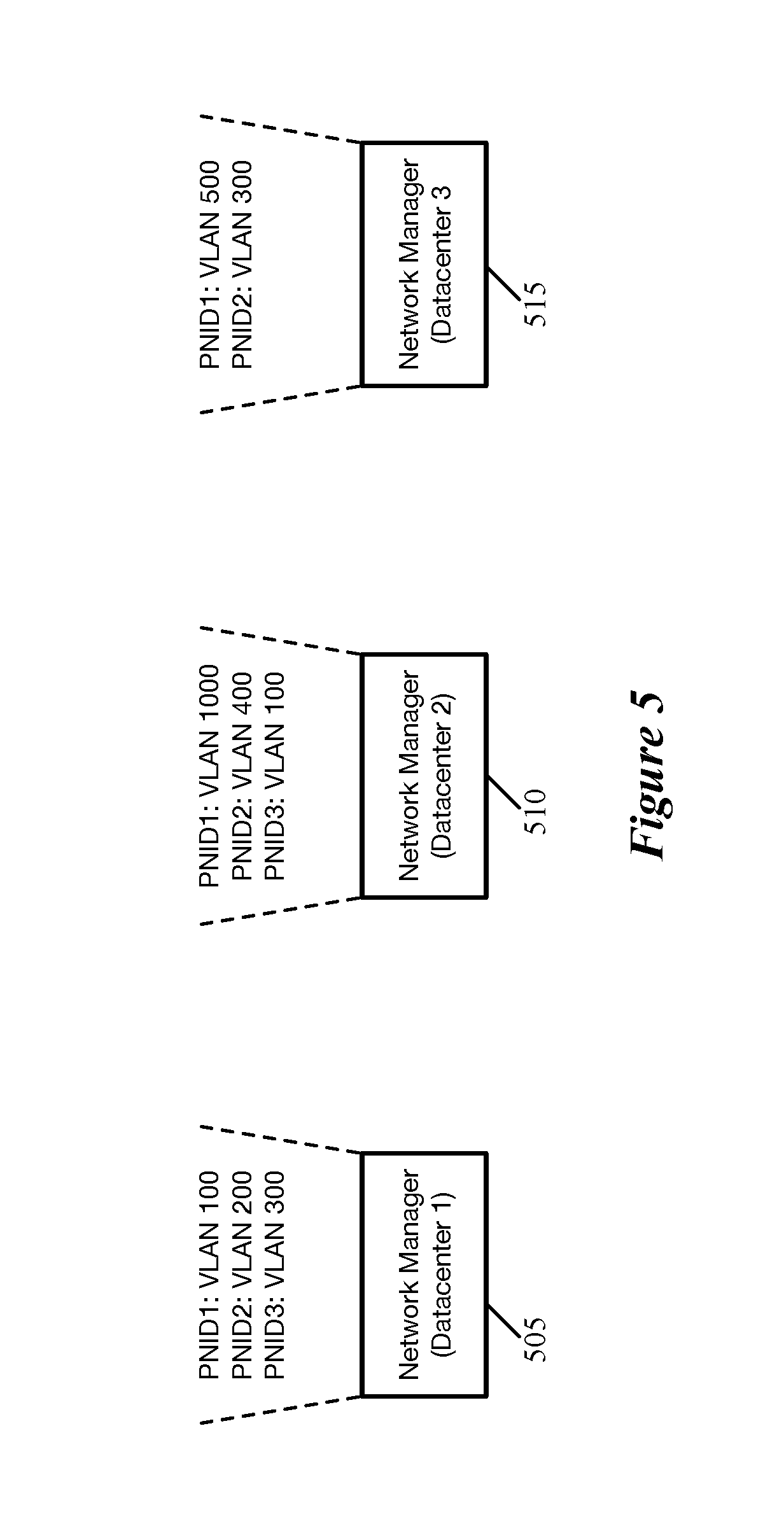
FIG. 5 conceptually illustrates the mapping of some embodiments of generic physical network identifiers to specific physical L2 networks by different network managers.
FIG. 6 conceptually illustrates a process of some embodiments for generating a bridge configuration 3-tuple based on a generic physical network identifier.
FIG. 7 conceptually illustrates an example of a failover scenario of some embodiments.
FIG. 8 conceptually illustrates an example of an active-active scenario of some embodiments for a bridge in two datacenters.
FIG. 9 conceptually illustrates an example of a broadcast packet being sent between bridges in different datacenters.
FIG. 10 conceptually illustrates an electronic system with which some embodiments of the invention are implemented.
DETAILED DESCRIPTION
In the following detailed description of the invention, numerous details, examples, and embodiments of the invention are set forth and described. However, it will be clear and apparent to one skilled in the art that the invention is not limited to the embodiments set forth and that the invention may be practiced without some of the specific details and examples discussed.
Some embodiments provide a method for implementing a bridge between a logical L2 network (e.g., a logical switch) that spans multiple datacenters and a physical L2 network located in one of the datacenters spanned by the logical network. In some embodiments, a network manager located at one of the datacenters receives the configuration for the bridge (e.g., from an administrator) and provides this configuration to a set of central controllers that manages the multiple datacenters, along with a datacenter identifier that specifies the particular datacenter in which the physical L2 network is located. The set of central controllers stores information about the managed forwarding elements at each of the datacenters managed by the central controllers, including datacenter identifiers. Using this data, the set of central controllers selects one of the managed forwarding elements that is located in the same datacenter as the physical L2 network. In addition, some embodiments also require that the selected managed forwarding element operate in a host machine on which a data compute node (e.g., a virtual machine) that connects to the logical network resides.
FIG. 1 conceptually illustrates a process 100 of some embodiments to select a managed forwarding element to implement a bridge between a logical network that spans multiple datacenters and a physical network at one of the datacenters. The process 100 is performed by a set of central controllers in some embodiments.
The process 100 will be described in part by reference to FIGS. 2 and 3. FIG. 2 illustrates a set of central controllers 200, as well as managed forwarding elements (MFEs) operating in two datacenters 205 and 210. The set of central controllers 200 may be a single controller, a cluster of controllers, etc. The controllers may be located, in different embodiments, at one or the other of the datacenters 205 and 210, divided between the datacenters, or located at a different location (e.g., at a datacenter other than these two).
The managed forwarding elements are configurable forwarding elements that receive configuration data distributed by the set of central controllers 200. In some embodiments, the managed forwarding elements are software forwarding elements (e.g., virtual switches, virtual routers, combined switch/router software modules, etc.) that execute within the virtualization software (e.g., hypervisors) of different host machines in the datacenters.
The process 100 begins by receiving (at 105) a bridge configuration as a three-tuple including (i) a logical network identifier, (ii) a physical network identifier, and (iii) a datacenter identifier. In some embodiments, this data is received from a network manager that operates at one of the datacenters (i.e., the datacenter specified by the datacenter identifier). The network manager receives the bridge configuration, e.g., through an application programming interface (API) based on user input to specify a bridge between a logical L2 network and a physical L2 network, and provides the configuration data (with the datacenter identifier) to the set of central controllers. In some embodiments, the network manager maps a generic physical network identifier in the configuration received through the API to a specific physical L2 network at the datacenter. This mapping performed by the network manager is explained in more detail below.
In FIG. 2, the set of central controllers 200 receives a bridge configuration identifying a logical L2 network with the identifier VXLAN 10, a physical L2 network with the identifier VLAN 100, and a datacenter identifier DC1. The logical network identifier, in some embodiments, specifies a particular logical switch (also referred to as a distributed virtual switch), such as a VXLAN network. A logical switch is an abstract of a switch defined by an administrator that logically connects data compute nodes (e.g., VMs, containers, etc.) that may not be connected to the same physical switch. In some embodiments, the data compute nodes connected to a logical switch may be distributed across multiple racks within a datacenter, or even multiple datacenters. When data compute nodes (DCNs) on the same logical switch communicate with each other, they do so as though they are connected to the same physical switch, while the physical network (e.g., the MFEs) between them uses, e.g., tunnel encapsulation to preserve this abstraction.
The physical network identifier, in some embodiments, identifies a VLAN or similar L2 construct that operates within a single datacenter. The physical L2 networks do not use an overlay network to communicate, and are thus confined to a single datacenter. Lastly, the datacenter identifier specifies a particular one of the datacenters that host machines connected to the logical network.
Next, the process 100 identifies (at 110) MFEs that (i) have the same datacenter identifier as the datacenter identifier received as part of the bridge configuration and (ii) operate on host machines on which DCNs of the logical network reside. In some embodiments, each DCN of the logical network directly connects to a managed forwarding element that operates on the same physical host machine as the DCN. In some embodiments, a set of MFEs (e.g., one or more virtual switches, virtual routers, etc.) operates on a physical host machine, and the process identifies MFEs that implement bridges that operate on the same host machine as the DCN. For instance, a virtual router might implement the bridge, while the DCN connects directly to a virtual switch which in turn connects to the virtual router. In the example shown in FIG. 2, each of MFE1, MFE2, and MFE3 would be identified as having the same datacenter identifier as specified by the bridge configuration, but not all of these would necessarily operate on the same physical host as a DCN attached to the logical network VXLAN 10.
The process 100 then selects (at 115) one of the identified MFEs (that meets the above criteria) to implement the bridge in the specified datacenter. Different embodiments may make the selection randomly or pseudo-randomly, using load balancing techniques (i.e., balancing the number of bridges for different logical networks that are implemented on the different MFEs of a datacenter), etc.
FIG. 3 conceptually illustrates an example of the selection of an MFE for a bridge by a central controller 300. As shown, the controller receives a bridge configuration (e.g., from a network manager) for a bridge between logical L2 network VXLAN 10, physical L2 network VLAN 100, in datacenter 1. The central controller 300 stores a mapping of each MFE in datacenters 1 and 2 to their respective datacenter identifier. Thus, the central controller can identify that MFE1, MFE2, and MFE3 have the same datacenter identifier as specified in the bridge configuration. In addition, the central controller stores (or calculates) the span of the logical L2 network VXLAN 10, which includes MFE1, MFE2, MFE4, and MFE6. These are the MFEs that are configured to implement VXLAN 10, for example because they operate on the same host machine on which DCNs belonging to VXLAN 10 reside. Based on this data, the central controller 300 can select either MFE1 or MFE2, and in this example selects MFE2.
Finally, the process 100 distributes (at 120) bridge configuration data to the selected MFE. The process then ends. In FIG. 2, the set of central controllers 300 selects MFE2, and distributes bridge configuration data to the MFE, instructing the MFE to set up a bridge between VXLAN 10 and VLAN 100. In some embodiments, the set of central controllers actually distributes this information as a data tuple to a local controller operating on the same host as the MFE (e.g., also in the virtualization software of the host machine). The local controller then converts the data tuple into configuration data for the specific type of MFE operating on the host (e.g., flow entries for a flow-based MFE, other types of configuration data for other types of MFEs). In addition, in some embodiments, the set of central controllers distribute to the other MFEs (at least those operating on host machines on which DCNs attached to the logical network reside) the location of the bridge as well as the list of addresses (e.g., MAC addresses) in each of the networks being bridged, so that packets requiring bridging can be identified and sent to MFE2.
The selected managed forwarding element bridges packets by, e.g., removing a logical network identifier from a packet and adding a physical network identifier (e.g., a VLAN tag), or vice versa. FIG. 4 conceptually illustrates an example of a MFE 400 operating to bridge a packet sent from a first DCN (VM1) on a logical network (VXLAN 10) to a second DCN (VM9) on a physical L2 network (VLAN 100). As shown, the first DCN 405 sends a unicast packet with its own MAC address as the source address and the MAC address of the second DCN 410 as the destination address.
The MFE 415 to which this first DCN connects processes the packet and determines that the packet requires bridging by the bridge MFE 400. As such, the MFE 415 tunnels the packet to the bridge MFE 400, using VXLAN encapsulation (which includes the VXLAN identifier in the outer encapsulation header). The bridge MFE 400 receives this packet, removes the encapsulation, and, based on the destination MAC address, determines that the packet needs to be bridged onto VLAN 100. As such, the bridge MFE 400 adds a VLAN tag (for VLAN 100) to the packet, and sends the packet onto the VLAN (which could involve tunneling the packet to a hardware switch, such as a TOR, that connects to the DCNs on the VLAN).
In the above example, the bridge is configured to operate in a specific datacenter in which the physical L2 network is located. In certain circumstances, the bridge may need to be implemented in multiple datacenters, either moving from one datacenter to another as a failover mechanism or in a configuration in which the bridge operates simultaneously in multiple datacenters at once (e.g., bridging physical L2 networks in multiple datacenters onto the same logical L2 network). Thus, some embodiments use a generic physical network identifier in the bridge configuration that maps to different specific physical L2 networks at different datacenters. The network managers at two different datacenters receive the same configuration specifying a bridge between a logical L2 network that spans the two datacenters and a physical network identifier. The first network manager (at the first datacenter) maps this physical network identifier to a first physical L2 network (e.g., a VLAN) at the first datacenter while the second network manager (at the second datacenter) maps this physical network identifier to a second physical L2 network at the second datacenter. The network managers, in some embodiments, provide the configurations to the set of central controllers using their respective datacenter identifiers and specific physical L2 network identifiers in order for the central controllers to select managed forwarding elements at the two different datacenters to which to provide the respective bridge configurations.
FIG. 5 conceptually illustrates the mapping of some embodiments of generic physical network identifiers to specific physical L2 networks by different network managers 505-515. As shown, these three network managers 505-515 operate in three different datacenters, and store their own separate mappings of generic physical network identifiers (PNIDs) to specific VLANs at their respective datacenters. Thus, if the first network manager 505 receives a bridge configuration including PNID2, the network manager 505 will map this to VLAN 200, and provide this (along with an identifier for datacenter 1) as part of the 3-tuple sent to the set of central controllers to setup the bridge. If the second network manager 510 receives the same bridge configuration with PNID2, this network manager 510 will map the PNID to its own VLAN 400, and provide this (along with an identifier for datacenter 2) as part of the 3-tuple sent to the set of central controllers to setup the bridge. As can be seen, the second datacenter also has a VLAN 100, though this is associated with PNID3 (which could be for a completely different tenant). In addition, not all of the PNIDs will necessarily map to physical L2 networks in all of the datacenters. In this case, PNID3 does not map to any network in the third datacenter.
FIG. 6 conceptually illustrates a process 600 of some embodiments for generating a bridge configuration 3-tuple based on a generic physical network identifier. The process 600 is performed, in some embodiments, by a network manager located at a particular datacenter. The network managers across the various datacenters, in some embodiments, form a management plane. The management plane provides APIs through which administrators (e.g., via cloud management software) provide logical network configuration, to set up logical switches, logical routers, distributed firewalls, bridges between logical switches and physical L2 networks, etc. Among other responsibilities, in some embodiments the management plane translates the configuration from the administrators into the configuration for distribution to the MFEs (or local controllers). The set of central controllers receives this configuration and determines to which MFEs (or local controllers) each piece of configuration data should be distributed (and performs this distribution).
As shown, the process 600 begins by receiving (at 605) a bridge configuration that includes a logical network identifier and a generic physical network identifier. As in the description above, the logical network identifier specifies a logical switch such as a VXLAN network, which in this case spans multiple datacenters. The generic physical network identifier, as mentioned, maps to different specific physical L2 networks at different datacenters.
Next, the process 600 maps (at 610) the generic physical network identifier to a specific physical network identifier for the datacenter. The specific physical network identifier represents a specific VLAN or other physical L2 network at the particular datacenter where the network manager operates, in some embodiments. As shown in FIG. 5, the network manager of some embodiments stores data mapping each generic physical network identifier to its corresponding local specific physical network identifier.
The process 600 then provides (at 615) the bridge configuration to the set of central controllers as a 3-tuple that includes the logical network identifier, the specific physical network identifier (to which the generic physical network identifier was mapped), and a datacenter identifier. As before, the datacenter identifier specifies the datacenter in which the bridge will be located, which is the datacenter of the network manager and the datacenter in which the specific physical L2 network is located. For the same bridge, different network managers will provide different configuration 3-tuples to the set of central controllers (though the logical network identifier will be the same between these 3-tuples).
As mentioned, one such circumstance of some embodiments that uses the generic physical network identifier involves moving the bridge from one datacenter to another. FIG. 7 conceptually illustrates an example of such a failover scenario of some embodiments over two stages 705 and 710. As shown in the first stage 705, the figure illustrates two network managers 715 and 720 located at two datacenters 725 and 730, respectively. Each of the datacenters 725 and 730 includes three MFEs, and there is a set of central controllers 700 that provides configuration data to the MFEs at both datacenters.
The first stage 705 illustrates the initial setup for a bridge at the first datacenter 705. In this stage, the first network manager 715 initially receives input requesting that a bridge be configured between the logical L2 network VXLAN 10 and the generic physical L2 network represented by PNID 2. The first network manager 715 provides this bridge configuration to the second network manager 720 (as well as the network managers at any other datacenters spanned by the logical L2 network), which does not yet act on this information. In addition, the first network manager 715 maps the PNID to its specific local physical L2 network VLAN 200 and provides the bridge configuration 3-tuple to the set of central controllers 700. This 3-tuple, as shown, specifies VXLAN 10 (the logical network for the bridge), VLAN 200 (the physical network for the bridge at datacenter 1), and the first datacenter 725.
Based on this data, the set of central controllers 700 configures the bridge on a managed forwarding element (MFE3) in the first datacenter 725 (e.g., by providing the configuration data to the local controller that manages this MFE). In addition, in some embodiments, the set of controllers 700 provides configuration data to each of the other MFEs in both datacenters (or at least the MFEs connected to DCNs on the logical network) so that those MFEs send packets requiring bridging to MFE3.
If the first network manager fails (e.g., the machine on which the first network manager operates fails, loses communication, etc.), some embodiments move the bridge to a second datacenter also spanned by the logical L2 network. This second datacenter may have a physical L2 network that acts as a backup for the physical L2 network at the first datacenter.
In the second stage, the network manager 715 fails, and the second network manager 720 is notified of this failure. This notification may occur based on a message sent from the central controllers 700 or elsewhere, or because the second network manager 720 can no longer reach the first network manager 715. The second network manager 720 maps the PNID for the bridge to its specific local physical L2 network VLAN 400 and provides the bridge configuration 3-tuple to the set of central controllers 700. This 3-tuple, as shown, specifies VXLAN 10 (the logical network for the bridge), VLAN 400 (the physical network for the bridge at datacenter 2), and the identifier for the second datacenter 730.
Based on this data, the set of central controllers 700 configures the bridge on a managed forwarding element (MFE4) in the second datacenter 730 (e.g., by providing the configuration data to the local controller that manages this MFE). In addition, in some embodiments, the set of controllers 700 provides configuration data to each of the other MFEs in both datacenters (or at least the MFEs connected to DCNs on the logical network) so that those MFEs send packets requiring bridging to MFE4.
The use of a generic physical network identifier also enables an active-active setup, with bridges operating on multiple datacenters to bridge different physical L2 networks onto the logical L2 network at the same time. To enable this scenario, each of the network managers at their respective datacenters maps the generic physical network identifier to their own specific physical L2 network, and provides their separate configuration to the set of central controllers, which configures bridges at each datacenter. Thus, the same traffic from a logical network DCN (e.g., broadcast or multicast traffic) can be bridged onto multiple physical L2 networks at different datacenters.
FIG. 8 conceptually illustrates an example of such an active-active scenario of some embodiments for a bridge in two datacenters 805 and 810. The figure illustrates two network managers 815 and 820 located at the two datacenters 805 and 810, respectively. Each of the datacenters 805 and 810 includes three MFEs, and the figure additionally illustrates a set of central controllers 800 that provides configuration data to the MFEs at both datacenters.
As shown, the network manager 815 at the first datacenter 805 initially receives input (e.g., through its API) requesting that a bridge be configured between the logical L2 network VXLAN 10 and the generic physical L2 network represented by PNID 2. The first network manager 815 provides this bridge configuration to the second network manager 820 at the second datacenter 810, as well as the network managers at any other datacenters spanned by the logical L2 network VXLAN 10.
Each of these network managers 815 and 820 maps the PNID to its respective specific physical L2 network (VLAN 200 for the first network manager 815 and VLAN 400 for the second network manager 820). In addition, each of the network managers 815 and 820 provides its respective bridge configuration 3-tuple to the set of central controllers 800. As shown, the first network manager 815 sends a 3-tuple specifying VXLAN 10 (the logical network for the bridge), VLAN 200 (the physical network for the bridge at the first datacenter), and the datacenter identifier for the first datacenter 805. The second network manager 820 sends a 3-tuple specifying VXLAN 10 (the same logical network for the bridge), VLAN 400 (the physical network for the bridge at the second datacenter), and the datacenter identifier for the second datacenter 810.
Based on the 3-tuple from the first network manager 815, the set of central controllers 800 selects a managed forwarding element (MFE2) in the first datacenter 805 and configures the bridge on this MFE (e.g., by providing the configuration data to the local controller that manages this MFE). As shown, MFE2 is configured as a bridge between VXLAN 10 and VLAN 200. In addition, based on the 3-tuple from the second network manager 820, the set of central controllers 800 selects a managed forwarding element (MFE4) in the second datacenter 810 and configures the bridge on this MFE (e.g., by providing the configuration data to the local controller that manages this MFE). As shown, MFE4 is configured as a bridge between VXLAN 10 and VLAN 400.
In addition, in some embodiments, the set of controllers provides configuration data to each of the other MFEs in both datacenters (or at least the MFEs connected to DCNs on the logical network) so that these MFEs send packets requiring bridging to MFE2 or MFE4. In some embodiments, an MFE always sends packets requiring bridging to the bridge in its respective datacenter. However, in other embodiments, each of the MFEs receives information about both bridges, so that packets that need to be bridged onto the physical network in the first datacenter can be sent to the bridge in the first datacenter and packets that need to be bridged onto the physical network in the second datacenter can be sent to the bridge in the second datacenter.
Having multiple physical L2 networks at different datacenters bridged onto the same logical network can create the possibility of traffic loops as well as undesired connectivity between the physical L2 networks at different datacenters. In general, the traffic that requires bridging is either unicast traffic from a DCN on the logical L2 network to a DCN on the physical L2 network (or vice versa) or BUM traffic (broadcast, unknown unicast, or multicast) traffic. Unicast traffic will typically not cause loops, and should not cause data packets to be sent from the physical L2 network in one datacenter to the physical L2 network in another datacenter (as those DCNs should not be sending each other traffic in the first place in such embodiments).
However, BUM traffic can create these issues. For instance, a broadcast packet sent from a DCN on the first datacenter's physical L2 network would be bridged onto the logical network by the bridge at the first datacenter, and (because it is a broadcast packet) would reach the bridge at the second datacenter, which would (at least) bridge the packet onto the physical L2 network at the second datacenter. In addition, if a bridge is present at three datacenters, then the first bridge to receive a broadcast packet from its physical L2 network would broadcast this packet to the second and third bridges. In processing the packet, the second bridge would send the packet to the third bridge (possibly avoiding sending the packet back to the first bridge because the packet is not sent out the port on which it was received). The third bridge would also send the packet to the second bridge for the same reason, and both of these bridges would send the packets to the first bridge, creating a loop.
In some embodiments, each time a packet is sent from one of the MFEs to another (including from a bridge in one datacenter to a bridge in another datacenter), the packet is encapsulated (e.g., using VXLAN, GENEVE, STT, etc.). Thus, to prevent traffic loops or having a physical L2 network in one datacenter send traffic to a physical L2 network in another datacenter, some embodiments use an available field or portion thereof (e.g., a single bit) in the tunnel encapsulation header to identify that a packet has already been bridged. When the managed forwarding element implementing the bridge receives such a packet, the forwarding element does not bridge the packet again, instead just delivering the packet to its destination (e.g., the logical network DCN residing on that host machine).
FIG. 9 conceptually illustrates an example of a broadcast packet being sent between bridges in different datacenters. As shown, the packet is initially sent from a first VM 905 on VLAN 200 in a first datacenter 910 to its local bridge MFE 915. The packet has a source MAC address of the sender VM (VM8) and the broadcast destination address (FFFFFFFFFFFF). The packet also includes a VLAN tag at this point. Though not shown, this packet would be broadcast to the other DCNs on VLAN 200 in the first datacenter as well.
The bridge MFE 915 in the first datacenter 910 receives and processes this packet, bridging the packet to the logical L2 network VXLAN 10. This includes delivering the packet to its local DCN 920 (VM1) that is connected to this logical L2 network, to which the packet is sent (after removing the VLAN tag). The packet is also tunneled to the other MFEs that have VMs on the logical L2 network, including the bridge(s) in other datacenters. In this case, the packet is tunneled to the bridge MFE 925 in the second datacenter 930, in addition to various other MFEs (not shown) in both the first and second datacenters. The encapsulation, as shown, includes the identifier for VXLAN 10, the source and destination IP addresses of tunnel endpoints at the two MFEs, as well as a bridged bit set to 1. This bridged bit identifies the packet as having been bridged, so that the MFE4 will not bridge the packet again.
The bridge MFE 925 receives the packet from the bridge MFE 915 and processes this packet. The MFE 925 delivers the packet to the VM 935, which is on the logical L2 network VXLAN 10. However, because the bridged bit is set in the packet, the MFE 925 does not send the packet out onto its local physical L2 network (and thus VM 940 does not receive the packet), as shown by the crossed-out arrow.
FIG. 10 conceptually illustrates an electronic system 1000 with which some embodiments of the invention are implemented. The electronic system 1000 can be used to execute any of the control, virtualization, or operating system applications described above. The electronic system 1000 may be a computer (e.g., a desktop computer, personal computer, tablet computer, server computer, mainframe, a blade computer etc.), phone, PDA, or any other sort of electronic device. Such an electronic system includes various types of computer readable media and interfaces for various other types of computer readable media. Electronic system 1000 includes a bus 1005, processing unit(s) 1010, a system memory 1025, a read-only memory 1030, a permanent storage device 1035, input devices 1040, and output devices 1045.
The bus 1005 collectively represents all system, peripheral, and chipset buses that communicatively connect the numerous internal devices of the electronic system 1000. For instance, the bus 1005 communicatively connects the processing unit(s) 1010 with the read-only memory 1030, the system memory 1025, and the permanent storage device 1035.
From these various memory units, the processing unit(s) 1010 retrieve instructions to execute and data to process in order to execute the processes of the invention. The processing unit(s) may be a single processor or a multi-core processor in different embodiments.
The read-only-memory (ROM) 1030 stores static data and instructions that are needed by the processing unit(s) 1010 and other modules of the electronic system. The permanent storage device 1035, on the other hand, is a read-and-write memory device. This device is a non-volatile memory unit that stores instructions and data even when the electronic system 1000 is off. Some embodiments of the invention use a mass-storage device (such as a magnetic or optical disk and its corresponding disk drive) as the permanent storage device 1035.
Other embodiments use a removable storage device (such as a floppy disk, flash drive, etc.) as the permanent storage device. Like the permanent storage device 1035, the system memory 1025 is a read-and-write memory device. However, unlike storage device 1035, the system memory is a volatile read-and-write memory, such a random-access memory. The system memory stores some of the instructions and data that the processor needs at runtime. In some embodiments, the invention's processes are stored in the system memory 1025, the permanent storage device 1035, and/or the read-only memory 1030. From these various memory units, the processing unit(s) 1010 retrieve instructions to execute and data to process in order to execute the processes of some embodiments.
The bus 1005 also connects to the input and output devices 1040 and 1045. The input devices enable the user to communicate information and select commands to the electronic system. The input devices 1040 include alphanumeric keyboards and pointing devices (also called "cursor control devices"). The output devices 1045 display images generated by the electronic system. The output devices include printers and display devices, such as cathode ray tubes (CRT) or liquid crystal displays (LCD). Some embodiments include devices such as a touchscreen that function as both input and output devices.
Finally, as shown in FIG. 10, bus 1005 also couples electronic system 1000 to a network 1065 through a network adapter (not shown). In this manner, the computer can be a part of a network of computers (such as a local area network ("LAN"), a wide area network ("WAN"), or an Intranet, or a network of networks, such as the Internet. Any or all components of electronic system 1000 may be used in conjunction with the invention.
Some embodiments include electronic components, such as microprocessors, storage and memory that store computer program instructions in a machine-readable or computer-readable medium (alternatively referred to as computer-readable storage media, machine-readable media, or machine-readable storage media). Some examples of such computer-readable media include RAM, ROM, read-only compact discs (CD-ROM), recordable compact discs (CD-R), rewritable compact discs (CD-RW), read-only digital versatile discs (e.g., DVD-ROM, dual-layer DVD-ROM), a variety of recordable/rewritable DVDs (e.g., DVD-RAM, DVD-RW, DVD+RW, etc.), flash memory (e.g., SD cards, mini-SD cards, micro-SD cards, etc.), magnetic and/or solid state hard drives, read-only and recordable Blu-Ray.RTM. discs, ultra-density optical discs, any other optical or magnetic media, and floppy disks. The computer-readable media may store a computer program that is executable by at least one processing unit and includes sets of instructions for performing various operations. Examples of computer programs or computer code include machine code, such as is produced by a compiler, and files including higher-level code that are executed by a computer, an electronic component, or a microprocessor using an interpreter.
While the above discussion primarily refers to microprocessor or multi-core processors that execute software, some embodiments are performed by one or more integrated circuits, such as application specific integrated circuits (ASICs) or field programmable gate arrays (FPGAs). In some embodiments, such integrated circuits execute instructions that are stored on the circuit itself.
As used in this specification, the terms "computer", "server", "processor", and "memory" all refer to electronic or other technological devices. These terms exclude people or groups of people. For the purposes of the specification, the terms display or displaying means displaying on an
D00000
D00001
D00002
D00003
D00004
D00005
D00006
D00007
D00008
D00009
D00010
XML
uspto.report is an independent third-party trademark research tool that is not affiliated, endorsed, or sponsored by the United States Patent and Trademark Office (USPTO) or any other governmental organization. The information provided by uspto.report is based on publicly available data at the time of writing and is intended for informational purposes only.
While we strive to provide accurate and up-to-date information, we do not guarantee the accuracy, completeness, reliability, or suitability of the information displayed on this site. The use of this site is at your own risk. Any reliance you place on such information is therefore strictly at your own risk.
All official trademark data, including owner information, should be verified by visiting the official USPTO website at www.uspto.gov. This site is not intended to replace professional legal advice and should not be used as a substitute for consulting with a legal professional who is knowledgeable about trademark law.