Motor stator structure
Yang , et al. Dec
U.S. patent number 10,511,203 [Application Number 15/653,533] was granted by the patent office on 2019-12-17 for motor stator structure. This patent grant is currently assigned to Asia Vital Components Co., Ltd.. The grantee listed for this patent is ASIA VITAL COMPONENTS CO., LTD.. Invention is credited to Kuo-Chen Chang, Yen-Chih Lu, Ching-Min Yang.


| United States Patent | 10,511,203 |
| Yang , et al. | December 17, 2019 |
Motor stator structure
Abstract
A motor stator structure includes a main body and multiple stopper plates. The main body has multiple magnetic poles and a shaft hole. The magnetic poles outward extend from the main body. Each magnetic pole has a free end outward extending from the main body. The shaft hole passes through the main body between two ends thereof. The stopper plates are respectively correspondingly assembled with the free ends of the magnetic poles. In the motor stator structure, the windings are more densely wound on the magnetic poles to enhance the magnetization efficiency.
| Inventors: | Yang; Ching-Min (New Taipei, TW), Chang; Kuo-Chen (New Taipei, TW), Lu; Yen-Chih (New Taipei, TW) | ||||||||||
|---|---|---|---|---|---|---|---|---|---|---|---|
| Applicant: |
|
||||||||||
| Assignee: | Asia Vital Components Co., Ltd.
(New Taipei, TW) |
||||||||||
| Family ID: | 65023561 | ||||||||||
| Appl. No.: | 15/653,533 | ||||||||||
| Filed: | July 19, 2017 |
Prior Publication Data
| Document Identifier | Publication Date | |
|---|---|---|
| US 20190027991 A1 | Jan 24, 2019 | |
| Current U.S. Class: | 1/1 |
| Current CPC Class: | H02K 1/185 (20130101); H02K 3/51 (20130101); H02K 3/493 (20130101); H02K 1/148 (20130101); H02K 3/522 (20130101); H02K 1/165 (20130101) |
| Current International Class: | H02K 1/06 (20060101); H02K 3/493 (20060101); H02K 3/51 (20060101); H02K 1/18 (20060101); H02K 1/16 (20060101) |
| Field of Search: | ;310/216.079 |
References Cited [Referenced By]
U.S. Patent Documents
| 5057733 | October 1991 | Sonoda |
| 5852335 | December 1998 | Suzuki |
| 5990584 | November 1999 | Luo et al. |
| 6815861 | November 2004 | Suzuki |
| 6822356 | November 2004 | Suzuki |
| 2002/0163275 | November 2002 | Hsu |
| 105071561 | Nov 2015 | CN | |||
| M407544 | Jul 2011 | TW | |||
Attorney, Agent or Firm: Nikolai; Thomas J. DeWitt LLP
Claims
What is claimed is:
1. A motor stator structure comprising: a main body having multiple magnetic poles and a shaft hole, the magnetic poles outward extending from the main body, each magnetic pole having a free end outward extending from the main body and a connection end opposite to the free end, the connection ends being connected with the main body, the shaft hole passing through the main body between two ends thereof; and multiple stopper plates respectively correspondingly assembled with the free ends of the magnetic poles; wherein a width of the free end is larger than a width of the connection end.
2. The motor stator structure as claimed in claim 1, wherein multiple windings are wound around the magnetic poles.
3. The motor stator structure as claimed in claim 1, wherein the main body is composed of multiple silicon steel sheets stacked on each other.
4. The motor stator structure as claimed in claim 1, wherein the magnetic poles are annularly arranged on an outer circumference of the main body.
5. The motor stator structure as claimed in claim 1, wherein a receiving space is defined between the adjacent magnetic poles.
Description
BACKGROUND OF THE INVENTION
1. Field of the Invention
The present invention relates generally to a motor stator structure, and more particularly to a motor stator structure in which the windings are more densely wound on the magnetic poles to enhance the magnetization effect.
2. Description of the Related Art
It is known that electrical energy is provided for the windings of the stator of a motor to create induced magnetic field. The magnetic field interacts with the magnetic member of the rotor around the stator to convert the electrical energy into dynamic energy so that the rotor of the motor can operate. The stator is mainly composed of multiple silicon steel sheets, which are stacked to form a stator main body with multiple magnetic poles. The magnetic poles are arranged at intervals to define therebetween a receiving space. A free end of each magnetic pole has a stopper section. With respect to a traditional stator, the windings are mainly wound on the magnetic poles manually. In order to mass-produce the motors, a winding apparatus has been developed to wind the windings on the magnetic poles.
The windings are wound on the magnetic poles to occupy the receiving space. The stopper sections serve to prevent the windings from dropping out. When winding the windings on the magnetic poles, the stopper sections often hinder the windings from being fully wound in the entire receiving space. Also, the windings can be hardly uniformly wound on the magnetic poles. This will affect the induction magnetization efficiency between the stator and the rotor. As a result, the operation performance of the motor will be deteriorated.
It is therefore tried by the applicant to provide a motor stator structure in which the windings are more densely wound on the magnetic poles to enhance the induction magnetization efficiency between the stator and the rotor.
SUMMARY OF THE INVENTION
It is therefore a primary object of the present invention to provide a motor stator structure in which the windings are more densely wound on the magnetic poles to enhance the magnetization effect.
To achieve the above and other objects, the motor stator structure of the present invention includes a main body and multiple stopper plates.
The main body has multiple magnetic poles and a shaft hole. The magnetic poles outward extend from the main body. Each magnetic pole has a free end outward extending from the main body. The shaft hole passes through the main body between two ends thereof. The stopper plates are respectively correspondingly assembled with the free ends of the magnetic poles.
In the motor stator structure of the present invention, the windings are wound around the magnetic poles and the stopper plates serve to prevent the windings from dropping out. The stopper plates are connected with the free ends of the magnetic poles by way of assembling process. In this case, when winding the windings, the stopper plates will not hinder the winding operation and the windings can be uniformly fully wound to occupy the entire receiving space. Accordingly, the induction magnetization efficiency between the stator and the rotor can be enhanced to promote the operation performance of the motor.
BRIEF DESCRIPTION OF THE DRAWINGS
The structure and the technical means adopted by the present invention to achieve the above and other objects can be best understood by referring to the following detailed description of the preferred embodiments and the accompanying drawings, wherein:
FIG. 1 is a perspective exploded view of a first embodiment of the motor stator structure of the present invention;
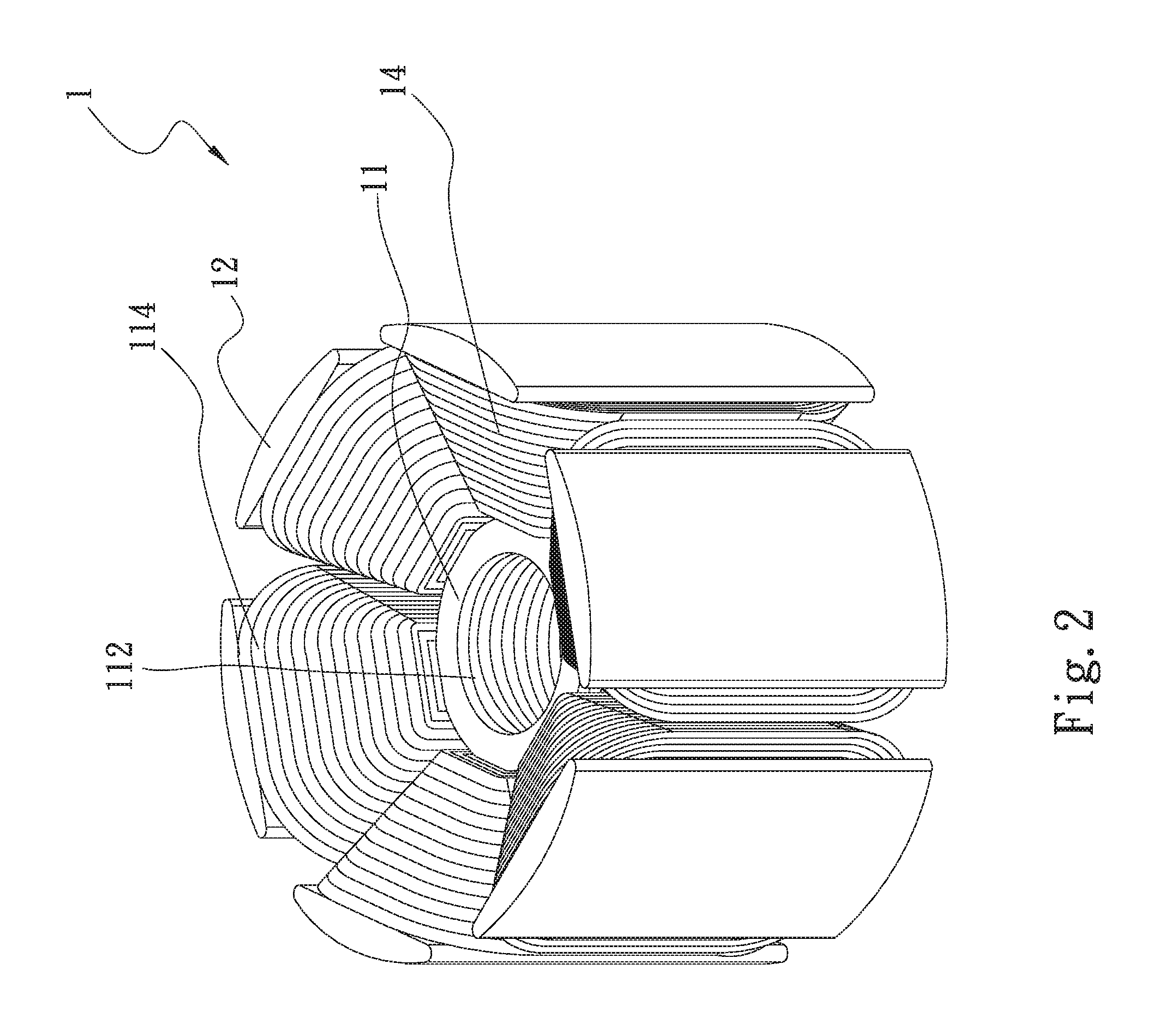
FIG. 2 is a perspective assembled view of the first embodiment of the motor stator structure of the present invention;
FIG. 3a is a top view of a second embodiment of the motor stator structure of the present invention;
FIG. 3b is a top view of the second embodiment of the motor stator structure of the present invention; and
FIG. 4 is a top view of a third embodiment of the motor stator structure of the present invention.
DETAILED DESCRIPTION OF THE PREFERRED EMBODIMENTS
Please refer to FIGS. 1 and 2. FIG. 1 is a perspective exploded view of a first embodiment of the motor stator structure of the present invention. FIG. 2 is a perspective assembled view of the first embodiment of the motor stator structure of the present invention. According to the first embodiment, the motor stator structure 1 of the present invention includes a main body 1 and multiple stopper plates 12.
The main body 11 has multiple magnetic poles 111 and a shaft hole 112. The magnetic poles 111 outward extend from the main body 11 and are annularly arranged on the outer circumference of the main body 11. Each magnetic pole 111 has a free end 111a outward extending from the main body 11. The shaft hole 112 passes through the main body 11 between two ends thereof. The main body 11 is composed of multiple silicon steel sheets 113 stacked on each other.
The stopper plates 12 are respectively correspondingly assembled with the free ends 111a of the magnetic poles 111. Multiple windings 114 are wound around the magnetic poles 111.
Please now refer to FIGS. 3a and 3b. FIG. 3a is a top view of a second embodiment of the motor stator structure of the present invention. FIG. 3b is a top view of the second embodiment of the motor stator structure of the present invention. The second embodiment is partially identical to the first embodiment in structure and thus will not be repeatedly described hereinafter. The second embodiment is different from the first embodiment in that the second embodiment has a receiving space 115. The receiving space 115 is defined by the adjacent magnetic poles 111 and the stopper plates 12. The configuration and size of the receiving space 115 are related to the number of the magnetic poles 111 and the distance between the magnetic poles 111.
In the case that the number of the magnetic poles 111 is less, then the receiving space 115 is larger and the receiving space 115 has a quadrangular configuration. In the case that the number of the magnetic poles 111 is more, then the receiving space 115 is smaller and the receiving space 115 has a triangular configuration.
Please now refer to FIG. 4, which is a top view of a third embodiment of the motor stator structure of the present invention. In the third embodiment, each magnetic pole 111 has a connection end 111b opposite to the free end 111a. The connection end 111b is connected with the main body 11. The width of the free end 111a is larger than the width of the connection end 111b.
The major object of the present invention is to connect the stopper plates 12 with the tail ends (the free ends 111a) of the magnetic poles 111 by way of assembling process. In this case, when winding the windings, the stopper plates 12 will not hinder the winding operation and the windings can be uniformly fully wound to occupy the entire receiving space 115. Finally, the stopper plates 12 are connected with the free ends 111a of the magnetic poles 111 to restrict the windings 114 from dropping.
The motor stator structure of the present invention can improve the problem of the conventional stator structure that the wires can be hardly uniformly wound on the magnetic poles 111. In the present invention, the wires can be uniformly wound on magnetic poles 111. Also, the windings 114 can be respectively wound on the magnetic poles 111 with specific configuration.
The present invention has been described with the above embodiments thereof and it is understood that many changes and modifications in such as the form or layout pattern or practicing step of the above embodiments can be carried out without departing from the scope and the spirit of the invention that is intended to be limited only by the appended claims.
* * * * *
D00000
D00001
D00002
D00003
D00004
D00005
XML
uspto.report is an independent third-party trademark research tool that is not affiliated, endorsed, or sponsored by the United States Patent and Trademark Office (USPTO) or any other governmental organization. The information provided by uspto.report is based on publicly available data at the time of writing and is intended for informational purposes only.
While we strive to provide accurate and up-to-date information, we do not guarantee the accuracy, completeness, reliability, or suitability of the information displayed on this site. The use of this site is at your own risk. Any reliance you place on such information is therefore strictly at your own risk.
All official trademark data, including owner information, should be verified by visiting the official USPTO website at www.uspto.gov. This site is not intended to replace professional legal advice and should not be used as a substitute for consulting with a legal professional who is knowledgeable about trademark law.