Antenna assembly for a vehicle
Thill Dec
U.S. patent number 10,511,086 [Application Number 16/237,678] was granted by the patent office on 2019-12-17 for antenna assembly for a vehicle. This patent grant is currently assigned to Airgain Incorporated. The grantee listed for this patent is Airgain Incorporated. Invention is credited to Kevin Thill.


| United States Patent | 10,511,086 |
| Thill | December 17, 2019 |
Antenna assembly for a vehicle
Abstract
An antenna assembly comprising a base, a modem, a top lid and a housing is disclosed herein. The antenna assembly is for a vehicle. The base is composed of an aluminum material. The modem is disposed within the base. The top lid is for the base, and the top lid comprises at least one antenna element disposed on an exterior surface thereof. The housing covers the top lid and base. The top lid and base act as an electro-magnetic barrier for the modem.
| Inventors: | Thill; Kevin (Scottsdale, AZ) | ||||||||||
|---|---|---|---|---|---|---|---|---|---|---|---|
| Applicant: |
|
||||||||||
| Assignee: | Airgain Incorporated (San
Diego, CA) |
||||||||||
| Family ID: | 68841381 | ||||||||||
| Appl. No.: | 16/237,678 | ||||||||||
| Filed: | January 1, 2019 |
| Current U.S. Class: | 1/1 |
| Current CPC Class: | H01Q 1/241 (20130101); H01Q 1/3275 (20130101); H01Q 1/02 (20130101); H01Q 21/28 (20130101); H01Q 1/2291 (20130101); H05K 1/0203 (20130101); H05K 1/0216 (20130101) |
| Current International Class: | H01Q 1/32 (20060101); H05K 1/02 (20060101); H01Q 1/22 (20060101); H01Q 1/02 (20060101); H01Q 1/24 (20060101) |
References Cited [Referenced By]
U.S. Patent Documents
| D418142 | December 1999 | Thill |
| 6087990 | July 2000 | Thill et al. |
| 6850191 | February 2005 | Thill et al. |
| 7061437 | June 2006 | Lin et al. |
| 7148849 | December 2006 | Lin |
| 7215296 | May 2007 | Abramov et al. |
| D546821 | July 2007 | Oliver |
| D549696 | August 2007 | Oshima et al. |
| 7333067 | February 2008 | Hung et al. |
| 7336959 | February 2008 | Khitrik et al. |
| D573589 | July 2008 | Montgomery et al. |
| 7405704 | August 2008 | Lin et al. |
| 7477195 | January 2009 | Vance |
| D592195 | May 2009 | Wu et al. |
| 7570215 | August 2009 | Abramov et al. |
| D599334 | September 2009 | Chiang |
| D606053 | December 2009 | Wu et al. |
| D607442 | January 2010 | Su et al. |
| D608769 | January 2010 | Bufe |
| D612368 | March 2010 | Yang et al. |
| 7705783 | April 2010 | Rao et al. |
| 7729662 | June 2010 | Abramov et al. |
| D621819 | August 2010 | Tsai et al. |
| 7843390 | November 2010 | Liu |
| D633483 | March 2011 | Su et al. |
| D635127 | March 2011 | Tsai et al. |
| 7907971 | March 2011 | Salo et al. |
| D635560 | April 2011 | Tsai et al. |
| D635963 | April 2011 | Podduturi |
| D635964 | April 2011 | Podduturi |
| D635965 | April 2011 | Mi et al. |
| D636382 | April 2011 | Podduturi |
| 7965242 | June 2011 | Abramov et al. |
| D649962 | December 2011 | Tseng et al. |
| D651198 | December 2011 | Mi et al. |
| D654059 | February 2012 | Mi et al. |
| D654060 | February 2012 | Ko et al. |
| D658639 | May 2012 | Huang et al. |
| D659129 | May 2012 | Mi et al. |
| D659685 | May 2012 | Huang et al. |
| D659688 | May 2012 | Huang et al. |
| 8175036 | May 2012 | Visuri et al. |
| 8184601 | May 2012 | Abramov et al. |
| D662916 | July 2012 | Huang et al. |
| 8248970 | August 2012 | Abramov et al. |
| D671097 | November 2012 | Mi et al. |
| 8310402 | November 2012 | Yang |
| D676429 | February 2013 | Gosalia et al. |
| D678255 | March 2013 | Ko et al. |
| 8423084 | April 2013 | Abramov et al. |
| D684565 | June 2013 | Wei |
| D685352 | July 2013 | Wei |
| D685772 | July 2013 | Zheng et al. |
| D686600 | July 2013 | Yang |
| D689474 | September 2013 | Yang et al. |
| D692870 | November 2013 | He |
| D694738 | December 2013 | Yang |
| D695279 | December 2013 | Yang et al. |
| D695280 | December 2013 | Yang et al. |
| 8654030 | February 2014 | Mercer |
| 8669903 | March 2014 | Thill et al. |
| D703195 | April 2014 | Zheng |
| D703196 | April 2014 | Zheng |
| D706247 | June 2014 | Zheng et al. |
| D706750 | June 2014 | Bringuir |
| D706751 | June 2014 | Chang et al. |
| D708602 | July 2014 | Gosalia et al. |
| D709053 | July 2014 | Chang et al. |
| D710832 | August 2014 | Yang |
| D710833 | August 2014 | Zheng et al. |
| 8854265 | October 2014 | Yang et al. |
| D716775 | November 2014 | Bidermann |
| 9432070 | August 2016 | Mercer |
| 9912043 | March 2018 | Yang |
| D823285 | July 2018 | Montgomery |
| D832241 | October 2018 | He et al. |
| 10109918 | October 2018 | Thill |
| 10164324 | December 2018 | He et al. |
| 2002/0003499 | January 2002 | Kouam et al. |
| 2002/0156576 | October 2002 | Annett |
| 2004/0222936 | November 2004 | Hung et al. |
| 2005/0073462 | April 2005 | Lin et al. |
| 2005/0190108 | September 2005 | Lin et al. |
| 2006/0208900 | September 2006 | Tavassoli Hozouri |
| 2007/0030203 | February 2007 | Tsai et al. |
| 2008/0150829 | June 2008 | Lin et al. |
| 2009/0002244 | January 2009 | Woo |
| 2009/0058739 | March 2009 | Konishi |
| 2009/0135072 | May 2009 | Ke et al. |
| 2009/0231186 | September 2009 | Barak |
| 2009/0262028 | October 2009 | Mumbru et al. |
| 2010/0188297 | July 2010 | Chen et al. |
| 2010/0283684 | November 2010 | Rabinovich |
| 2010/0309067 | December 2010 | Tsou et al. |
| 2011/0006950 | January 2011 | Park et al. |
| 2012/0038514 | February 2012 | Bang |
| 2012/0229348 | September 2012 | Chiang |
| 2012/0242546 | September 2012 | Hu et al. |
| 2017/0054204 | February 2017 | Changalvala et al. |
| 2017/0317409 | November 2017 | Ayatollahi |
Attorney, Agent or Firm: Clause Eight IPS Catania; Michael
Claims
I claim as my invention the following:
1. An antenna assembly comprising: a base composed of an aluminum material, the base comprising a body, an interior surface, a sidewall and a plurality of heat dissipation elements extending upward from the interior surface; a modem disposed within the base and directly contacting the plurality of heat dissipation elements, the modem comprising at least one of a communication chip, a GNSS reception component, a security access module, or a mobile phone communication component; a top lid for the base, the top lid disposed on the sidewall of the base, the top lid and base defining an interior compartment for the plurality of heat dissipation elements and the modem, the top lid comprising a bottom surface composed of an aluminum material and a plurality of antenna elements disposed on an exterior surface, the plurality of elements comprising a multi-band antenna for cellular communications, a GPS/GLONASS module and a WiFi antenna; and a housing covering the top lid and base, the housing having a height ranging from 50-90 millimeters (mm), a length ranging from 100-250 mm, and a width ranging from 50-100 mm; wherein the top lid and the base act as an electro-magnetic barrier for the modem allowing the modem to be placed in proximity to the plurality of antenna elements without interference from electro-magnetic signals from the plurality of antenna elements; wherein the plurality of heat dissipation elements dissipate heat generated by operation of the modem.
2. The antenna assembly according to claim 1 further comprising a radiofrequency cable connected to the modem.
3. The antenna assembly according to claim 1 wherein the base is composed of a die-cast aluminum material.
4. The antenna assembly according to claim 1 wherein the top lid comprises a base circuit board.
5. The antenna assembly according to claim 1 wherein the top lid comprises a cell circuit board.
6. The antenna assembly according to claim 1 wherein the top lid comprises a WiFi circuit board.
7. The antenna assembly according to claim 1 wherein the base has a width ranging from 2.5 inches to 3.5 inches, and a length ranging from 6.o inches to 8.0 inches.
8. The antenna assembly according to claim 1 wherein the base has a height ranging from 0.5 inch to 1.0 inch.
9. A wireless communication assembly for a vehicle comprising: a base composed of an aluminum material for attached to the vehicle, the base comprising a body, an interior surface, a sidewall and a plurality of heat dissipation elements extending upward from the interior surface; a modem disposed within the base and directly contacting the plurality of heat dissipation elements, the modem comprising at least one of a communication chip, a GNSS reception component, a security access module, or a mobile phone communication component; a top lid for the base, the top lid disposed on the sidewall of the base, the top lid and base defining an interior compartment for the plurality of heat dissipation elements and the modem, the top lid comprising a bottom surface composed of an aluminum material and a plurality of antenna elements disposed on an exterior surface, the plurality of elements comprising a multi-band antenna for cellular communications, a GPS/GLONASS module and a WiFi antenna; and a housing covering the top lid and base, the housing having a height ranging from 50-90 millimeters (mm), a length ranging from 100-250 mm, and a width ranging from 50-100 mm; wherein the top lid and the base act as an electro-magnetic barrier for the modem allowing the modem to be placed in proximity to the plurality of antenna elements without interference from electro-magnetic signals from the plurality of antenna elements; wherein the plurality of heat dissipation elements dissipate heat generated by operation of the modem.
10. The wireless communication assembly according to claim 9 further comprising a radiofrequency cable connected to the modem.
11. The wireless communication assembly according to claim 9 wherein the base is composed of a die-cast aluminum material.
12. The wireless communication assembly according to claim 9 wherein the top lid comprises a base circuit board.
13. The wireless communication assembly according to claim 9 wherein the top lid comprises a cell circuit board.
14. The wireless communication assembly according to claim 9 wherein the top lid comprises a WiFi circuit board.
15. The wireless communication assembly according to claim 9 wherein the base has a width ranging from 2.5 inches to 3.5 inches, and a length ranging from 6.0 inches to 8.0 inches.
16. The wireless communication assembly according to claim 9 wherein the base has a height ranging from 0.5 inch to 1.0 inch.
Description
CROSS REFERENCE TO RELATED APPLICATION
Not Applicable
STATEMENT REGARDING FEDERALLY SPONSORED RESEARCH OR DEVELOPMENT
Not Applicable
BACKGROUND OF THE INVENTION
Field of the Invention
This invention relates to antenna assemblies for vehicles.
Description of the Related Art
In wireless communication systems for vehicles, a modem for the vehicle is typically placed a great distance away from an antenna in order to prevent electro-magnetic signals from the modem from interfering with the antenna. This often requires a long coaxial cable wired throughout the vehicle.
General definitions for terms utilized in the pertinent art are set forth below.
BLUETOOTH technology is a standard short range radio link that operates in the unlicensed 2.4 gigahertz band.
Code Division Multiple Access ("CDMA") is a spread spectrum communication system used in second generation and third generation cellular networks, and is described in U.S. Pat. No. 4,901,307.
GSM, Global System for Mobile Communications is a second generation digital cellular network.
The Universal Mobile Telecommunications System ("UMTS") is a wireless standard.
Long Term Evolution ("LTE") is a standard for wireless communication of high-speed data for mobile phones and data terminals and is based on the GSM/EDGE and UMTS/HSPA communication network technologies.
LTE Frequency Bands include 698-798 MHz (Band 12, 13, 14, 17); 791-960 MHz (Band 5, 6, 8, 18, 19, 20); 1710-2170 MHz (Band 1, 2, 3, 4, 9, 10, 23, 25, 33, 34, 35, 36, 37, 39); 1427-1660.5 MH (Band 11, 21, 24); 2300-2700 MHz (Band 7, 38, 40, 41); 3400-3800 MHz (Band 22, 42, 43).
Antenna impedance and the quality of the impedance match are most commonly characterized by either return loss or Voltage Standing Wave Ratio.
Surface Mount Technology ("SMT") is a process for manufacturing electronic circuits wherein the components are mounted or placed directly onto a surface of a printed circuit board ("PCB").
The APPLE IPHONE.RTM. 5 LTE Bands include: LTE700/1700/2100 (698-806 MHz/1710-1785 MHz/1920-2170 MHz); LTE 850/1800/2100 (824-894 MHz/1710-1880 MHz/1920-2170 MHz); and LTE 700/850/1800/1900/2100 (698-806 MHz/824-894 MHz/1710-1880 MHz/1850-1990 MHz/1920/2170).
The SAMSUNG GALAXY.RTM. Sill LTE Bands include: LTE 800/1800/2600 (806-869 MHz/1710-1880 MHz/2496-2690 MHz.
The NOKIA LUMIA.RTM. 920 LTE Bands: LTE 700/1700/2100 (698-806 MHz/1710-1785 MHz/1920-2170 MHz); LTE 800/900/1800/2100/2600 (806-869 MHz/880-960 MHz/1710-1880 MHz/1920-2170 MHz/2496-2690 MHz).
The long coaxial cable that connects a modem to an antenna on a vehicle leads to signal losses due to the length of the coaxial cable. Thus, there is a need for placement of a modem in proximity of an antenna for a vehicle system.
BRIEF SUMMARY OF THE INVENTION
One aspect of the present invention is an antenna assembly comprising a base, a modem, a top lid and a housing. The base is composed of an aluminum material. The modem is disposed on the base. The top lid is for the base, and the top lid comprises at least one antenna element disposed on an exterior surface. The housing covers the top lid and base. The top lid acts as an electro-magnetic barrier for the modem.
Another aspect of the present invention is a wireless communication assembly for a vehicle comprising a base, a modem, a top lid and a housing. The base is composed of an aluminum material and attached to the vehicle. The modem is disposed on the base. The top lid is for the base, and the top lid comprises at least one antenna element disposed on an exterior surface. The housing covers the top lid and base. The top lid acts as an electro-magnetic barrier for the modem.
Having briefly described the present invention, the above and further objects, features and advantages thereof will be recognized by those skilled in the pertinent art from the following detailed description of the invention when taken in conjunction with the accompanying drawings.
BRIEF DESCRIPTION OF THE SEVERAL VIEWS OF THE DRAWINGS
FIG. 1 is an exploded view of an antenna assembly for a vehicle.
FIG. 2 is a top plan view of a base portion of an antenna assembly for a vehicle.
FIG. 3 is a side elevation of the base portion of FIG. 2.
FIG. 4 is a side elevation view of a housing for an antenna assembly for a vehicle.
FIG. 5 is a side elevation view of an antenna assembly for a vehicle with a partial cut-away view.
FIG. 6 is a top plan view of an antenna assembly for a vehicle.
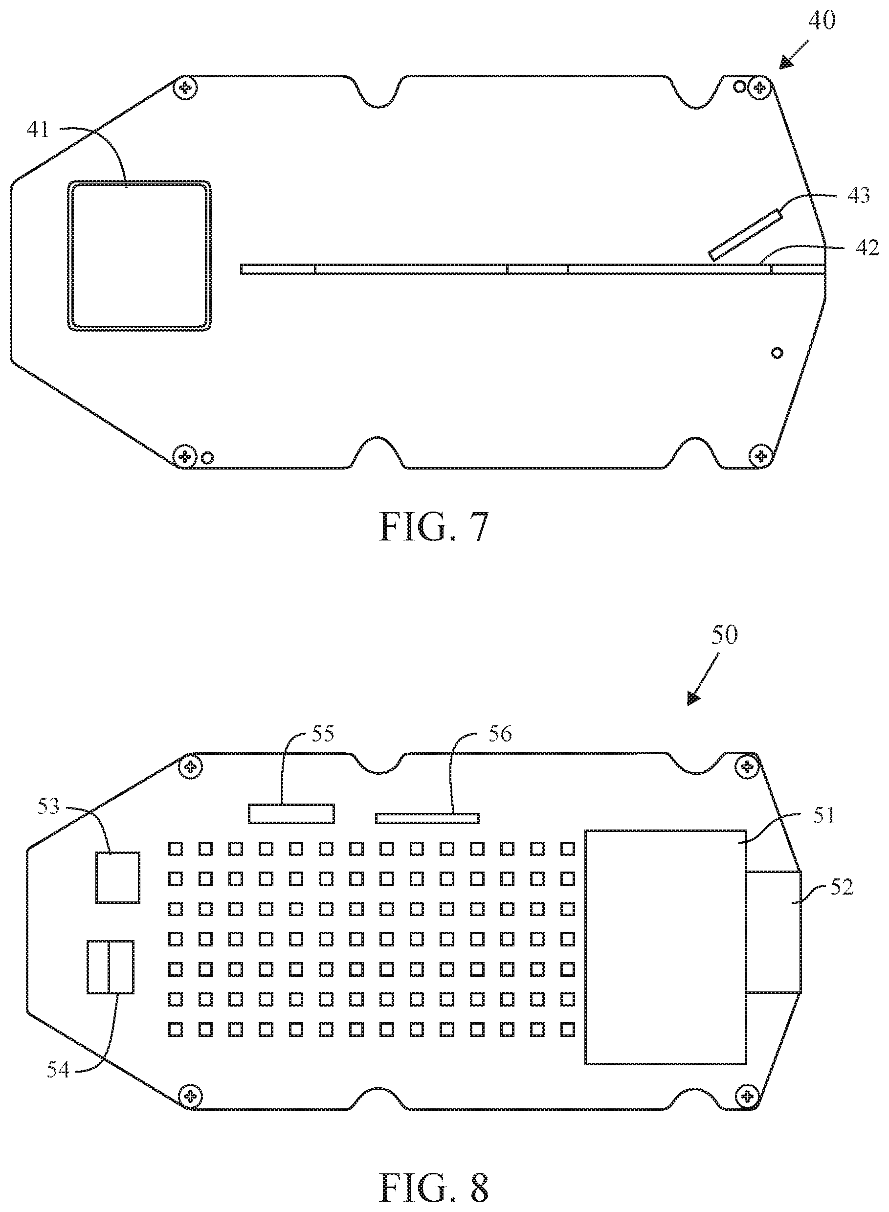
FIG. 7 is a top plan view of a top lid for an antenna assembly for a vehicle.
FIG. 8 is a top plan view of a modem for an antenna assembly for a vehicle.
DETAILED DESCRIPTION OF THE INVENTION
An antenna assembly 25 is shown in FIG. 1. The antenna assembly preferably comprises a base 60, a modem 50, a top lid 40 and a housing 30. The base 60 is preferably composed of an aluminum material. The modem 50 is disposed on the base 60. The top lid 40 is to cover the base 60 and modem 50, and the top lid 40 preferably comprises at least one antenna element disposed on an exterior surface. A radiofrequency cable 70 is attached to the modem 50 and secured to the base 60 by bolt 71. The housing 30 covers the top lid 40 and the base 60. The top lid 40 acts as an electro-magnetic barrier for the modem 50 to maintain the electro-magnetic signals inside of the base 60 to prevent interference with the antenna signals.
As shown in FIGS. 2 and 3, the base 60 includes a body 61 with an interior surface 62. A side wall 63 defines an interior compartment 65 in which a first plurality of heat dissipation elements 66a-66e and a second plurality of heat dissipation elements 67a-67e. An aperture 64 extends through the body 61 for access by at least one cable. The base 60 is preferably composed of a die-cast aluminum material to prevent electro-magnetic signals from the modem 50 from interfering with the antennas on the top lid 40. In this manner, the modem 50 is capable of being placed in proximity to the antennas on the top lid 50 without interference from electro-magnetic signals with the antennas on the top lid 40.
The first plurality of heat dissipation elements 66a-66e and the second plurality of heat dissipation elements 67a-67e dissipate heat that is generate by the operation of the modem 50.
The sidewall 63, in addition to acting as electro-magnetic barrier, also provides a structure for placement of the top lid 40 thereon.
As shown in FIG. 3, the base 60 preferably has a height H2 ranging from 0.5 inch to 1.0 inch, a height, H1, ranging from 0.05 inch to 0.15 inch, and a height, H3, ranging from 0.15 inch to 0.30 inch The base preferably has a width ranging from 2.5 inches to 3.5 inches, and a length, L1, ranging from 6.0 inches to 8.0 inches. The aperture 64 is preferably from 1.0 inch to 1.25 inches across.
As shown in FIG. 7, the top lid 40 comprises a first antenna element 42, a second antenna element 43 and a third antenna element 41. Preferably the first antenna element 42 is a multi-band antenna for cellular communications such as disclosed in Thill, U.S. patent Ser. No. 10/109,918 for a Multi-Element Antenna For Multiple bands Of Operation And Method Therefor, which is hereby incorporated by reference in tis entirety. Alternatively, the first antenna element 42 is a multi-band antenna for cellular communications such as disclosed in He, U.S. Pat. No. 9,362,621 for a Multi-Band LTE Antenna, which is hereby incorporated by reference in tis entirety.
Preferably, the second antenna element 43 is selected from the group of antennas consisting of a WiFi 2G antenna, a WiFi 5G antenna, a DECT antenna, a ZigBee antenna and a Zwave antenna. The WiFi 2G antennas are preferably 2400-2690 MegaHertz. The WiFi 5G antenna is preferably a 5.8 GigaHertz antenna. Alternatively, the second antenna element 43 operates at 5.15 GHz or at 5.85 GHz. Other possible frequencies for the second antenna element 43 include 5150 MHz, 5200 MHz, 5300 MHz, 5400 MHz, 5500 MHz, 5600 MHz, 5700 MHz, 5850 MHz, and 2.4 GHz. The second antenna element 43 preferably operates on an 802.11 communication protocol. Most preferably, the second antenna element 43 operates on an 802.11n communication protocol. Alternatively, the second antenna element 43 operates on an 802.11b communication protocol. Alternatively, the second antenna element 43 operates on an 802.11g communication protocol. Alternatively, the second antenna element 43 operates on an 802.11a communication protocol. Alternatively, the second antenna element 43 operates on an 802.11ac communication protocol.
The third antenna element 41 is preferably a GPS/GLONASS module.
Those skilled in the pertinent art will recognize that other antenna types may be used for the first antenna element 42, the second antenna element 43 and/or the third antenna element 41 without departing from the scope and spirit of the present invention.
The top lid 40 is preferably composed of an aluminum material, at least on a bottom surface. Alternatively, the top lid 40 is composed of materials that can act as a barrier to electro-magnetic signals.
The modem 50 preferably includes at least one of a computation component, a communication chip 55, a switch, an antenna switch circuit, a GNSS reception component 56, a security access module 53, a mobile phone communication component 54, and a power supply source. The computation component preferably includes a CPU 51, a memory 52, and an interface (I/F) component. The modem 50 preferably operates for vehicle to everything (V2X) communications, using a 802.11p communication protocol. Alternatively, the modem 50 operates Dedicated Short Range Communications (DSRC). Alternatively, the modem 50 operates cellular V2X (CV2X) using 5G technology.
Preferably, the housing 30 is composed of a polypropylene material. As shown in FIGS. 4, 5 and 6, the housing 30 preferably has a height, H4, ranging from 50 to 90 millimeters (mm), more preferably from 60 to 80 mm, and most preferably from 65 to 75 mm. The housing 30 preferably has a length, L2, ranging from 100 to 250 mm, more preferably from 150 to 200 mm, and most preferably from 160 to 190 mm. The housing 30 preferably has a width, W1 ranging from 50 to 100 mm, more preferably from 60 to 90 mm, and most preferably from 65 to 85 mm. An internal width W2 is preferably 70 to 80 mm. A width W3 is preferably 10 to 15 mm. The housing 30 has a sidewall 32, a crown 33 and a rear wall 31. The walls of the housing 30 preferably have a thickness ranging from 2 to 7 mm, and most preferably are 5 mm.
He, U.S. Pat. No. 9,362,621 for a Multi-Band LTE Antenna is hereby incorporated by reference in its entirety.
Abramov et al., U.S. Pat. No. 7,215,296 for a Switch Multi-Beam Antenna Serial is hereby incorporated by reference in its entirety.
Salo et al., U.S. Pat. No. 7,907,971 for an Optimized Directional Antenna System is hereby incorporated by reference in its entirety.
Abramov et al., U.S. Pat. No. 7,570,215 for an Antenna device with a controlled directional pattern and a planar directional antenna is hereby incorporated by reference in its entirety.
Abramov et al., U.S. Pat. No. 7,570,215 for an Antenna device with a controlled directional pattern and a planar directional antenna is hereby incorporated by reference in its entirety.
Abramov et al., U.S. Pat. No. 8,423,084 for a Method for radio communication in a wireless local area network and transceiving device is hereby incorporated by reference in its entirety.
Khitrik et al., U.S. Pat. No. 7,336,959 for an Information transmission method for a wireless local network is hereby incorporated by reference in its entirety.
Khitrik et al., U.S. Pat. No. 7,043,252 for an Information transmission method for a wireless local network is hereby incorporated by reference in its entirety.
Abramov et al., U.S. Pat. No. 8,184,601 for a METHOD FOR RADIO COMMUNICATION INA WIRELESS LOCAL AREA NETWORK WIRELESS LOCAL AREA NETWORK AND TRANSCEIVING DEVICE is hereby incorporated by reference in its entirety.
Abramov et al., U.S. Pat. No. 7,627,300 for a Dynamically optimized smart antenna system is hereby incorporated by reference in its entirety.
Abramov et al., U.S. Pat. No. 6,486,832 for a Direction-agile antenna system for wireless communications is hereby incorporated by reference in its entirety.
Yang, U.S. Pat. No. 8,081,123 for a COMPACT MULTI-LEVEL ANTENNA WITH PHASE SHIFT is hereby incorporated by reference in its entirety.
Nagaev et al., U.S. Pat. No. 7,292,201 for a Directional antenna system with multi-use elements is hereby incorporated by reference in its entirety.
Abramov et al., U.S. Pat. No. 7,696,948 for a Configurable directional antenna is hereby incorporated by reference in its entirety.
Abramov et al., U.S. Pat. No. 7,965,242 for a Dual-band antenna is hereby incorporated by reference in its entirety.
Abramov et al., U.S. Pat. No. 7,729,662 for a Radio communication method in a wireless local network is hereby incorporated by reference in its entirety.
Abramov et al., U.S. Pat. No. 8,248,970 for an OPTIMIZED DIRECTIONAL MIMO ANTENNA SYSTEM is hereby incorporated by reference in its entirety.
Visuri et al., U.S. Pat. No. 8,175,036 for a MULTIMEDIA WIRELESS DISTRIBUTION SYSTEMS AND METHODS is hereby incorporated by reference in its entirety.
Yang, U.S. Patent Publication Number 20110235755 for an MIMO Radio System With Antenna Signal Combiner is hereby incorporated by reference in its entirety.
Yang et al., U.S. Pat. No. 9,013,355 for an L SHAPED FEED AS PART OF A MATCHING NETWORK FOR A MICROSTRIP ANTENNA is hereby incorporated by reference in its entirety.
From the foregoing it is believed that those skilled in the pertinent art will recognize the meritorious advancement of this invention and will readily understand that while the present invention has been described in association with a preferred embodiment thereof, and other embodiments illustrated in the accompanying drawings, numerous changes modification and substitutions of equivalents may be made therein without departing from the spirit and scope of this invention which is intended to be unlimited by the foregoing except as may appear in the following appended claim. Therefore, the embodiments of the invention in which an exclusive property or privilege is claimed are defined in the following appended claims.
* * * * *
D00000
D00001
D00002
D00003
D00004
D00005
XML
uspto.report is an independent third-party trademark research tool that is not affiliated, endorsed, or sponsored by the United States Patent and Trademark Office (USPTO) or any other governmental organization. The information provided by uspto.report is based on publicly available data at the time of writing and is intended for informational purposes only.
While we strive to provide accurate and up-to-date information, we do not guarantee the accuracy, completeness, reliability, or suitability of the information displayed on this site. The use of this site is at your own risk. Any reliance you place on such information is therefore strictly at your own risk.
All official trademark data, including owner information, should be verified by visiting the official USPTO website at www.uspto.gov. This site is not intended to replace professional legal advice and should not be used as a substitute for consulting with a legal professional who is knowledgeable about trademark law.