Optical displays
Robbins , et al. Dec
U.S. patent number 10,509,241 [Application Number 14/465,763] was granted by the patent office on 2019-12-17 for optical displays. This patent grant is currently assigned to DIGILENS INC., ROCKWELL COLLINS, INC.. The grantee listed for this patent is Digilens Inc., Rockwell Collins, Inc.. Invention is credited to Robert D. Brown, Alastair J. Grant, Wyatt L. Hendrick, Milan M. Popovich, Francois Raynal, Steven J. Robbins, James H. Stanley, James M. Tedesco, Jonathan D. Waldern.


| United States Patent | 10,509,241 |
| Robbins , et al. | December 17, 2019 |
Optical displays
Abstract
An apparatus for providing an optical display includes an optical substrate for propagating light received from a light source, a first set of one or more switchable diffractive elements in the substrate, and a second set of one or more switchable diffractive elements in the substrate. Each diffractive element in the second set corresponds to a diffractive element in the first set. Each of the diffractive elements in the first and second sets is configured to switch between on and off states. One of the states is for diffracting light and the other state for allowing light to pass through. Each of the first set of diffractive elements is configured to diffract the light at an angle for propagation in the substrate. Each of the second set of diffractive elements is configured to diffract the light for display.
| Inventors: | Robbins; Steven J. (San Jose, CA), Stanley; James H. (Palo Alto, CA), Raynal; Francois (San Jose, CA), Brown; Robert D. (Lake Oswego, OR), Tedesco; James M. (Livonia, MI), Hendrick; Wyatt L. (San Diego, CA), Popovich; Milan M. (Leicester, GB), Waldern; Jonathan D. (Los Altos Hills, CA), Grant; Alastair J. (San Jose, CA) | ||||||||||
|---|---|---|---|---|---|---|---|---|---|---|---|
| Applicant: |
|
||||||||||
| Assignee: | ROCKWELL COLLINS, INC. (Cedar
Rapids, IA) DIGILENS INC. (Sunnyvale, CA) |
||||||||||
| Family ID: | 46547624 | ||||||||||
| Appl. No.: | 14/465,763 | ||||||||||
| Filed: | August 21, 2014 |
Related U.S. Patent Documents
| Application Number | Filing Date | Patent Number | Issue Date | ||
|---|---|---|---|---|---|
| 13355360 | Jan 20, 2012 | 8817350 | |||
| 12571262 | Sep 30, 2009 | 8233204 | |||
| Current U.S. Class: | 1/1 |
| Current CPC Class: | G02B 27/01 (20130101); G02B 27/017 (20130101); G02B 5/18 (20130101); G02B 26/0808 (20130101); G02B 27/0149 (20130101); G02B 5/32 (20130101); G02B 27/0103 (20130101); G02F 1/01 (20130101); G02B 5/1828 (20130101); G02B 6/00 (20130101); G03H 1/30 (20130101); G03H 2001/2226 (20130101); Y10S 359/90 (20130101); G02B 2027/0152 (20130101); G02F 2201/305 (20130101) |
| Current International Class: | G02B 5/32 (20060101); G02F 1/01 (20060101); G09G 5/00 (20060101); G02B 27/01 (20060101); G02B 5/18 (20060101) |
| Field of Search: | ;359/566,568,15,900,1 ;385/31,37 ;345/7 |
References Cited [Referenced By]
U.S. Patent Documents
| 2141884 | December 1938 | Sonnefeld |
| 3620601 | November 1971 | Waghorn |
| 3851303 | November 1974 | Muller |
| 3885095 | May 1975 | Wolfson et al. |
| 3940204 | February 1976 | Withrington |
| 4082432 | April 1978 | Kirschner |
| 4099841 | July 1978 | Ellis |
| 4178074 | December 1979 | Heller |
| 4218111 | August 1980 | Withrington et al. |
| 4232943 | November 1980 | Rogers |
| 4309070 | January 1982 | St. Leger Searle |
| 4647967 | March 1987 | Kirschner et al. |
| 4711512 | December 1987 | Upatnieks |
| 4714320 | December 1987 | Banbury |
| 4743083 | May 1988 | Schimpe |
| 4749256 | June 1988 | Bell et al. |
| 4775218 | October 1988 | Wood et al. |
| 4799765 | January 1989 | Ferrer |
| 4854688 | August 1989 | Hayford et al. |
| 4928301 | May 1990 | Smoot |
| 4946245 | August 1990 | Chamberlin et al. |
| 5007711 | April 1991 | Wood et al. |
| 5035734 | July 1991 | Honkanen et al. |
| 5076664 | December 1991 | Migozzi |
| 5079416 | January 1992 | Filipovich |
| 5117285 | May 1992 | Nelson et al. |
| 5124821 | June 1992 | Antier et al. |
| 5148302 | September 1992 | Nagano et al. |
| 5151958 | September 1992 | Honkanen |
| 5153751 | October 1992 | Ishikawa et al. |
| 5159445 | October 1992 | Gitlin et al. |
| 5160523 | November 1992 | Honkanen et al. |
| 5183545 | February 1993 | Branca et al. |
| 5187597 | February 1993 | Kato et al. |
| 5210624 | May 1993 | Matsumoto et al. |
| 5218360 | June 1993 | Goetz et al. |
| 5243413 | September 1993 | Gitlin et al. |
| 5289315 | February 1994 | Makita et al. |
| 5295208 | March 1994 | Caulfield et al. |
| 5303085 | April 1994 | Rallison |
| 5317405 | May 1994 | Kuriki et al. |
| 5341230 | August 1994 | Smith |
| 5351151 | September 1994 | Levy |
| 5359362 | October 1994 | Lewis et al. |
| 5363220 | November 1994 | Kuwayama et al. |
| 5369511 | November 1994 | Amos |
| 5400069 | March 1995 | Braun et al. |
| 5408346 | April 1995 | Trissel et al. |
| 5418584 | May 1995 | Larson |
| 5438357 | August 1995 | McNelley |
| 5455693 | October 1995 | Wreede et al. |
| 5471326 | November 1995 | Hall et al. |
| 5473222 | December 1995 | Thoeny et al. |
| 5496621 | March 1996 | Makita et al. |
| 5500671 | March 1996 | Andersson et al. |
| 5510913 | April 1996 | Hashimoto et al. |
| 5515184 | May 1996 | Caulfield et al. |
| 5524272 | June 1996 | Podowski et al. |
| 5532736 | July 1996 | Kuriki et al. |
| 5537232 | July 1996 | Biles |
| 5572248 | November 1996 | Allen et al. |
| 5579026 | November 1996 | Tabata |
| 5583795 | December 1996 | Smyth |
| 5604611 | February 1997 | Saburi et al. |
| 5606433 | February 1997 | Yin et al. |
| 5612733 | March 1997 | Flohr |
| 5612734 | March 1997 | Nelson et al. |
| 5619254 | April 1997 | McNelley |
| 5629259 | May 1997 | Akada et al. |
| 5631107 | May 1997 | Tarumi et al. |
| 5633100 | May 1997 | Mickish et al. |
| 5646785 | July 1997 | Gilboa et al. |
| 5648857 | July 1997 | Ando et al. |
| 5661577 | August 1997 | Jenkins et al. |
| 5661603 | August 1997 | Hanano et al. |
| 5665494 | September 1997 | Kawabata et al. |
| 5668907 | September 1997 | Veligdan |
| 5682255 | October 1997 | Friesem et al. |
| 5694230 | December 1997 | Welch |
| 5701132 | December 1997 | Kollin et al. |
| 5706108 | January 1998 | Ando et al. |
| 5707925 | January 1998 | Akada et al. |
| 5724189 | March 1998 | Ferrante |
| 5726782 | March 1998 | Kato et al. |
| 5727098 | March 1998 | Jacobson |
| 5729242 | March 1998 | Margerum et al. |
| 5731060 | March 1998 | Hirukawa et al. |
| 5731853 | March 1998 | Taketomi et al. |
| 5742262 | April 1998 | Tabata et al. |
| 5751452 | May 1998 | Tanaka et al. |
| 5760931 | June 1998 | Saburi et al. |
| 5764414 | June 1998 | King et al. |
| 5790288 | August 1998 | Jager et al. |
| 5812608 | September 1998 | Valimaki et al. |
| 5822127 | October 1998 | Chen et al. |
| 5841507 | November 1998 | Barnes |
| 5856842 | January 1999 | Tedesco |
| 5868951 | February 1999 | Schuck et al. |
| 5886822 | March 1999 | Spitzer |
| 5892598 | April 1999 | Asakawa et al. |
| 5898511 | April 1999 | Mizutani et al. |
| 5903395 | May 1999 | Rallison et al. |
| 5907416 | May 1999 | Hegg et al. |
| 5907436 | May 1999 | Perry et al. |
| 5917459 | June 1999 | Son et al. |
| 5926147 | July 1999 | Sehm et al. |
| 5929946 | July 1999 | Sharp et al. |
| 5937115 | August 1999 | Domash |
| 5942157 | August 1999 | Sutherland et al. |
| 5945893 | August 1999 | Plessky et al. |
| 5949302 | September 1999 | Sarkka |
| 5966223 | October 1999 | Friesem et al. |
| 5985422 | November 1999 | Krauter |
| 5991087 | November 1999 | Rallison |
| 5999314 | December 1999 | Asakura et al. |
| 6042947 | March 2000 | Asakura et al. |
| 6043585 | March 2000 | Plessky et al. |
| 6075626 | June 2000 | Mizutani et al. |
| 6078427 | June 2000 | Fontaine et al. |
| 6115152 | September 2000 | Popovich et al. |
| 6127066 | October 2000 | Ueda et al. |
| 6137630 | October 2000 | Tsou et al. |
| 6169613 | January 2001 | Amitai et al. |
| 6176837 | January 2001 | Foxlin |
| 6195206 | February 2001 | Yona et al. |
| 6222675 | April 2001 | Mall et al. |
| 6222971 | April 2001 | Veligdan et al. |
| 6249386 | June 2001 | Yona et al. |
| 6259423 | July 2001 | Tokito et al. |
| 6259559 | July 2001 | Kobayashi et al. |
| 6285813 | September 2001 | Schultz et al. |
| 6317083 | November 2001 | Johnson et al. |
| 6317227 | November 2001 | Mizutani et al. |
| 6321069 | November 2001 | Piirainen |
| 6327089 | December 2001 | Hosaki et al. |
| 6333819 | December 2001 | Svedenkrans |
| 6340540 | January 2002 | Ueda et al. |
| 6351333 | February 2002 | Araki et al. |
| 6356172 | March 2002 | Koivisto et al. |
| 6359730 | March 2002 | Tervonen |
| 6359737 | March 2002 | Stringfellow |
| 6366378 | April 2002 | Tervonen et al. |
| 6392812 | May 2002 | Howard |
| 6409687 | June 2002 | Foxlin |
| 6470132 | October 2002 | Nousiainen et al. |
| 6486997 | November 2002 | Bruzzone et al. |
| 6504518 | January 2003 | Kuwayama et al. |
| 6524771 | February 2003 | Maeda et al. |
| 6545778 | April 2003 | Ono et al. |
| 6550949 | April 2003 | Bauer et al. |
| 6557413 | May 2003 | Nieminen et al. |
| 6563648 | May 2003 | Gleckman et al. |
| 6580529 | June 2003 | Amitai et al. |
| 6583873 | June 2003 | Goncharov et al. |
| 6587619 | July 2003 | Kinoshita |
| 6598987 | July 2003 | Parikka |
| 6608720 | August 2003 | Freeman |
| 6611253 | August 2003 | Cohen |
| 6646810 | November 2003 | Harter et al. |
| 6661578 | December 2003 | Hedrick |
| 6674578 | January 2004 | Sugiyama et al. |
| 6686815 | February 2004 | Mirshekarl-Syahkal et al. |
| 6690516 | February 2004 | Aritake et al. |
| 6721096 | April 2004 | Bruzzone et al. |
| 6741189 | May 2004 | Gibbons, II et al. |
| 6744478 | June 2004 | Asakura et al. |
| 6748342 | June 2004 | Dickhaus |
| 6750941 | June 2004 | Satoh et al. |
| 6750995 | June 2004 | Dickson |
| 6757105 | June 2004 | Niv et al. |
| 6771403 | August 2004 | Endo et al. |
| 6776339 | August 2004 | Piikivi |
| 6781701 | August 2004 | Sweetser et al. |
| 6805490 | October 2004 | Levola |
| 6825987 | November 2004 | Repetto et al. |
| 6829095 | December 2004 | Amitai |
| 6833955 | December 2004 | Niv |
| 6836369 | December 2004 | Fujikawa et al. |
| 6844212 | January 2005 | Bond et al. |
| 6844980 | January 2005 | He et al. |
| 6847274 | January 2005 | Salmela et al. |
| 6847488 | January 2005 | Travis |
| 6853491 | February 2005 | Ruhle et al. |
| 6864861 | March 2005 | Schehrer et al. |
| 6864927 | March 2005 | Cathey |
| 6885483 | April 2005 | Takada |
| 6903872 | June 2005 | Schrader |
| 6909345 | June 2005 | Salmela et al. |
| 6917375 | July 2005 | Akada et al. |
| 6922267 | July 2005 | Endo et al. |
| 6926429 | August 2005 | Barlow et al. |
| 6940361 | September 2005 | Jokio et al. |
| 6950173 | September 2005 | Sutherland et al. |
| 6950227 | September 2005 | Schrader |
| 6951393 | October 2005 | Koide |
| 6952312 | October 2005 | Weber et al. |
| 6958662 | October 2005 | Salmela et al. |
| 6987908 | January 2006 | Bond et al. |
| 7003187 | February 2006 | Frick et al. |
| 7018744 | March 2006 | Otaki et al. |
| 7021777 | April 2006 | Amitai |
| 7026892 | April 2006 | Kajiya |
| 7027671 | April 2006 | Huck et al. |
| 7034748 | April 2006 | Kajiya |
| 7053735 | May 2006 | Salmela et al. |
| 7058434 | June 2006 | Wang et al. |
| 7095562 | August 2006 | Peng et al. |
| 7101048 | September 2006 | Travis |
| 7110184 | September 2006 | Yona et al. |
| 7123418 | October 2006 | Weber et al. |
| 7126418 | October 2006 | Hunton et al. |
| 7126583 | October 2006 | Breed |
| 7132200 | November 2006 | Ueda et al. |
| 7149385 | December 2006 | Parikka et al. |
| 7151246 | December 2006 | Fein et al. |
| 7158095 | January 2007 | Jenson et al. |
| 7181105 | February 2007 | Teramura et al. |
| 7181108 | February 2007 | Levola |
| 7184615 | February 2007 | Levola |
| 7190849 | March 2007 | Katase |
| 7199934 | April 2007 | Yamasaki |
| 7205960 | April 2007 | David |
| 7205964 | April 2007 | Yokoyama et al. |
| 7206107 | April 2007 | Levola |
| 7230767 | June 2007 | Walck et al. |
| 7242527 | July 2007 | Spitzer et al. |
| 7248128 | July 2007 | Mattila et al. |
| 7259906 | August 2007 | Islam |
| 7268946 | September 2007 | Wang |
| 7285903 | October 2007 | Cull et al. |
| 7286272 | October 2007 | Mukawa |
| 7289069 | October 2007 | Ranta |
| 7299983 | November 2007 | Piikivi |
| 7313291 | December 2007 | Okhotnikov et al. |
| 7319573 | January 2008 | Nishiyama |
| 7320534 | January 2008 | Sugikawa et al. |
| 7323275 | January 2008 | Otaki et al. |
| 7336271 | February 2008 | Ozeki et al. |
| 7339737 | March 2008 | Urey et al. |
| 7339742 | March 2008 | Amitai et al. |
| 7375870 | May 2008 | Schorpp |
| 7391573 | June 2008 | Amitai |
| 7394865 | July 2008 | Borran et al. |
| 7395181 | July 2008 | Foxlin |
| 7397606 | July 2008 | Peng et al. |
| 7401920 | July 2008 | Kranz et al. |
| 7404644 | July 2008 | Evans et al. |
| 7410286 | August 2008 | Travis |
| 7411637 | August 2008 | Weiss |
| 7415173 | August 2008 | Kassamakov et al. |
| 7418170 | August 2008 | Mukawa et al. |
| 7433116 | October 2008 | Islam |
| 7436568 | October 2008 | Kuykendall, Jr. |
| 7454103 | November 2008 | Parriaux |
| 7457040 | November 2008 | Amitai |
| 7466994 | December 2008 | Pihlaja et al. |
| 7479354 | January 2009 | Ueda et al. |
| 7480215 | January 2009 | Makela et al. |
| 7482996 | January 2009 | Larson et al. |
| 7483604 | January 2009 | Levola |
| 7492512 | February 2009 | Niv et al. |
| 7496293 | February 2009 | Shamir et al. |
| 7500104 | March 2009 | Goland |
| 7528385 | May 2009 | Volodin et al. |
| 7545429 | June 2009 | Travis |
| 7550234 | June 2009 | Otaki et al. |
| 7567372 | July 2009 | Schorpp |
| 7570429 | August 2009 | Maliah et al. |
| 7572555 | August 2009 | Takizawa et al. |
| 7573640 | August 2009 | Nivon et al. |
| 7576916 | August 2009 | Amitai |
| 7577326 | August 2009 | Amitai |
| 7579119 | August 2009 | Ueda et al. |
| 7588863 | September 2009 | Takizawa et al. |
| 7589900 | September 2009 | Powell |
| 7589901 | September 2009 | Dejong et al. |
| 7592988 | September 2009 | Katase |
| 7593575 | September 2009 | Houle et al. |
| 7597447 | October 2009 | Larson et al. |
| 7599012 | October 2009 | Nakamura et al. |
| 7600893 | October 2009 | Laino et al. |
| 7602552 | October 2009 | Blumenfeld |
| 7616270 | November 2009 | Hirabayashi et al. |
| 7618750 | November 2009 | Ueda et al. |
| 7629086 | December 2009 | Otaki et al. |
| 7639911 | December 2009 | Lee et al. |
| 7643214 | January 2010 | Amitai |
| 7656585 | February 2010 | Powell et al. |
| 7660047 | February 2010 | Travis et al. |
| 7672055 | March 2010 | Amitai |
| 7710654 | May 2010 | Ashkenazi et al. |
| 7724441 | May 2010 | Amitai |
| 7724442 | May 2010 | Amitai |
| 7724443 | May 2010 | Amitai |
| 7733572 | June 2010 | Brown et al. |
| 7747113 | June 2010 | Mukawa et al. |
| 7751122 | July 2010 | Amitai |
| 7764413 | July 2010 | Levola |
| 7777819 | August 2010 | Simmonds |
| 7778305 | August 2010 | Parriaux et al. |
| 7778508 | August 2010 | Hirayama |
| 7847235 | December 2010 | Krupkin et al. |
| 7864427 | January 2011 | Korenaga et al. |
| 7865080 | January 2011 | Hecker et al. |
| 7872804 | January 2011 | Moon et al. |
| 7884985 | February 2011 | Amitai et al. |
| 7887186 | February 2011 | Watanabe |
| 7903921 | March 2011 | Ostergard |
| 7907342 | March 2011 | Simmonds et al. |
| 7920787 | April 2011 | Gentner et al. |
| 7944428 | May 2011 | Travis |
| 7969644 | June 2011 | Tilleman et al. |
| 7970246 | June 2011 | Travis et al. |
| 7976208 | July 2011 | Travis |
| 7999982 | August 2011 | Endo et al. |
| 8000491 | August 2011 | Brodkin et al. |
| 8004765 | August 2011 | Amitai |
| 8016475 | September 2011 | Travis |
| 8022942 | September 2011 | Bathiche et al. |
| RE42992 | December 2011 | David |
| 8079713 | December 2011 | Ashkenazi |
| 8082222 | December 2011 | Rangarajan et al. |
| 8086030 | December 2011 | Gordon et al. |
| 8089568 | January 2012 | Brown et al. |
| 8107023 | January 2012 | Simmonds et al. |
| 8107780 | January 2012 | Simmonds |
| 8132948 | March 2012 | Owen et al. |
| 8132976 | March 2012 | Odell et al. |
| 8136690 | March 2012 | Fang et al. |
| 8137981 | March 2012 | Andrew et al. |
| 8149086 | April 2012 | Klein et al. |
| 8152315 | April 2012 | Travis et al. |
| 8155489 | April 2012 | Saarikko et al. |
| 8159752 | April 2012 | Wertheim et al. |
| 8160409 | April 2012 | Large |
| 8160411 | April 2012 | Levola et al. |
| 8186874 | May 2012 | Sinbar et al. |
| 8188925 | May 2012 | Dejean |
| 8189263 | May 2012 | Wang et al. |
| 8189973 | May 2012 | Travis et al. |
| 8199803 | June 2012 | Hauske et al. |
| 8213065 | July 2012 | Mukawa |
| 8233204 | July 2012 | Robbins et al. |
| 8253914 | August 2012 | Kajiya et al. |
| 8254031 | August 2012 | Levola |
| 8295710 | October 2012 | Marcus |
| 8301031 | October 2012 | Gentner et al. |
| 8305577 | November 2012 | Kivioja et al. |
| 8306423 | November 2012 | Gottwald et al. |
| 8314819 | November 2012 | Kimmel et al. |
| 8321810 | November 2012 | Heintze |
| 8335040 | December 2012 | Mukawa et al. |
| 8351744 | January 2013 | Travis et al. |
| 8354806 | January 2013 | Travis et al. |
| 8355610 | January 2013 | Simmonds |
| 8369019 | February 2013 | Baker et al. |
| 8384694 | February 2013 | Powell et al. |
| 8398242 | March 2013 | Yamamoto et al. |
| 8403490 | March 2013 | Sugiyama et al. |
| 8422840 | April 2013 | Large |
| 8427439 | April 2013 | Larsen et al. |
| 8432363 | April 2013 | Saarikko et al. |
| 8432372 | April 2013 | Butler et al. |
| 8472119 | June 2013 | Kelly |
| 8472120 | June 2013 | Border et al. |
| 8477261 | July 2013 | Travis et al. |
| 8491121 | July 2013 | Tilleman et al. |
| 8491136 | July 2013 | Travis et al. |
| 8493366 | July 2013 | Bathiche et al. |
| 8493662 | July 2013 | Noui |
| 8508848 | August 2013 | Saarikko |
| 8547638 | October 2013 | Levola |
| 8578038 | November 2013 | Kaikuranta et al. |
| 8581831 | November 2013 | Travis |
| 8582206 | November 2013 | Travis |
| 8593734 | November 2013 | Laakkonen |
| 8611014 | December 2013 | Valera et al. |
| 8619062 | December 2013 | Powell et al. |
| 8633786 | January 2014 | Ermolov et al. |
| 8634139 | January 2014 | Brown et al. |
| 8639072 | January 2014 | Popovich et al. |
| 8643691 | February 2014 | Rosenfeld et al. |
| 8649099 | February 2014 | Schultz et al. |
| 8654420 | February 2014 | Simmonds |
| 8659826 | February 2014 | Brown et al. |
| 8670029 | March 2014 | McEldowney |
| 8693087 | April 2014 | Nowatzyk et al. |
| 8736802 | May 2014 | Kajiya et al. |
| 8736963 | May 2014 | Robbins et al. |
| 8749886 | June 2014 | Gupta |
| 8749890 | June 2014 | Wood et al. |
| 8767294 | July 2014 | Chen et al. |
| 8810600 | August 2014 | Bohn et al. |
| 8814691 | August 2014 | Haddick et al. |
| 8830584 | September 2014 | Saarikko et al. |
| 8903207 | December 2014 | Brown et al. |
| 8913324 | December 2014 | Schrader |
| 8937772 | January 2015 | Burns et al. |
| 8938141 | January 2015 | Magnusson |
| 8964298 | February 2015 | Haddick et al. |
| 9244280 | January 2016 | Tiana et al. |
| 9341846 | May 2016 | Popovich et al. |
| 9366864 | June 2016 | Brown et al. |
| 9456744 | October 2016 | Popovich et al. |
| 9523852 | December 2016 | Brown et al. |
| 9632226 | April 2017 | Waldern et al. |
| 9933684 | April 2018 | Brown et al. |
| 2002/0021461 | February 2002 | Ono et al. |
| 2002/0127497 | September 2002 | Brown et al. |
| 2002/0131175 | September 2002 | Yagi et al. |
| 2003/0030912 | February 2003 | Gleckman et al. |
| 2003/0039442 | February 2003 | Bond et al. |
| 2003/0063042 | April 2003 | Friesem et al. |
| 2003/0149346 | August 2003 | Arnone et al. |
| 2003/0228019 | December 2003 | Eichler et al. |
| 2004/0089842 | May 2004 | Sutherland et al. |
| 2004/0130797 | July 2004 | Leigh Travis |
| 2004/0188617 | September 2004 | Devitt et al. |
| 2004/0208446 | October 2004 | Bond et al. |
| 2004/0208466 | October 2004 | Mossberg et al. |
| 2005/0135747 | June 2005 | Greiner et al. |
| 2005/0136260 | June 2005 | Garcia |
| 2005/0259302 | November 2005 | Metz et al. |
| 2005/0269481 | December 2005 | David et al. |
| 2006/0093793 | May 2006 | Miyakawa et al. |
| 2006/0114564 | June 2006 | Sutherland et al. |
| 2006/0119916 | June 2006 | Sutherland et al. |
| 2006/0132914 | June 2006 | Weiss et al. |
| 2006/0221448 | October 2006 | Nivon et al. |
| 2006/0228073 | October 2006 | Mukawa et al. |
| 2006/0279662 | December 2006 | Kapellner et al. |
| 2006/0291021 | December 2006 | Mukawa |
| 2007/0019152 | January 2007 | Caputo et al. |
| 2007/0019297 | January 2007 | Stewart et al. |
| 2007/0041684 | February 2007 | Popovich et al. |
| 2007/0045596 | March 2007 | King et al. |
| 2007/0052929 | March 2007 | Allman et al. |
| 2007/0089625 | April 2007 | Grinberg et al. |
| 2007/0133920 | June 2007 | Lee et al. |
| 2007/0133983 | June 2007 | Traff |
| 2007/0188837 | August 2007 | Shimizu et al. |
| 2007/0211164 | September 2007 | Olsen et al. |
| 2008/0043334 | February 2008 | Itzkovitch et al. |
| 2008/0106775 | May 2008 | Amitai et al. |
| 2008/0136923 | June 2008 | Inbar et al. |
| 2008/0151379 | June 2008 | Amitai |
| 2008/0186604 | August 2008 | Amitai |
| 2008/0198471 | August 2008 | Amitai |
| 2008/0278812 | November 2008 | Amitai |
| 2008/0285140 | November 2008 | Amitai |
| 2008/0309586 | December 2008 | Vitale |
| 2009/0010135 | January 2009 | Ushiro et al. |
| 2009/0017424 | January 2009 | Yoeli et al. |
| 2009/0019222 | January 2009 | Verma et al. |
| 2009/0052046 | February 2009 | Amitai |
| 2009/0052047 | February 2009 | Amitai |
| 2009/0067774 | March 2009 | Magnusson |
| 2009/0097122 | April 2009 | Niv |
| 2009/0097127 | April 2009 | Amitai |
| 2009/0121301 | May 2009 | Chang |
| 2009/0122413 | May 2009 | Hoffman et al. |
| 2009/0122414 | May 2009 | Amitai |
| 2009/0128902 | May 2009 | Niv et al. |
| 2009/0128911 | May 2009 | Itzkovitch et al. |
| 2009/0153437 | June 2009 | Aharoni |
| 2009/0190222 | July 2009 | Simmonds et al. |
| 2009/0213208 | August 2009 | Glatt |
| 2009/0237804 | September 2009 | Amitai et al. |
| 2009/0303599 | December 2009 | Levola |
| 2009/0316246 | December 2009 | Asai et al. |
| 2010/0039796 | February 2010 | Mukawa |
| 2010/0060551 | March 2010 | Sugiyama et al. |
| 2010/0060990 | March 2010 | Wertheim et al. |
| 2010/0079865 | April 2010 | Saarikko et al. |
| 2010/0092124 | April 2010 | Magnusson et al. |
| 2010/0096562 | April 2010 | Klunder et al. |
| 2010/0103078 | April 2010 | Mukawa et al. |
| 2010/0136319 | June 2010 | Imai et al. |
| 2010/0141555 | June 2010 | Rorberg et al. |
| 2010/0165465 | July 2010 | Levola |
| 2010/0171680 | July 2010 | Lapidot et al. |
| 2010/0177388 | July 2010 | Cohen et al. |
| 2010/0214659 | August 2010 | Levola |
| 2010/0231693 | September 2010 | Levola |
| 2010/0231705 | September 2010 | Yahav et al. |
| 2010/0232003 | September 2010 | Baldy et al. |
| 2010/0246003 | September 2010 | Simmonds et al. |
| 2010/0246004 | September 2010 | Simmonds |
| 2010/0246993 | September 2010 | Rieger et al. |
| 2010/0265117 | October 2010 | Weiss |
| 2010/0277803 | November 2010 | Pockett et al. |
| 2010/0284085 | November 2010 | Laakkonen |
| 2010/0284180 | November 2010 | Popovich et al. |
| 2010/0296163 | November 2010 | Saarikko |
| 2010/0315719 | December 2010 | Saarikko |
| 2010/0321781 | December 2010 | Levola et al. |
| 2011/0002143 | January 2011 | Saarikko et al. |
| 2011/0013423 | January 2011 | Selbrede et al. |
| 2011/0019250 | January 2011 | Aiki et al. |
| 2011/0019874 | January 2011 | Jarvenpaa et al. |
| 2011/0026128 | February 2011 | Baker et al. |
| 2011/0026774 | February 2011 | Flohr et al. |
| 2011/0038024 | February 2011 | Wang et al. |
| 2011/0050548 | March 2011 | Blumenfeld et al. |
| 2011/0096401 | April 2011 | Levola |
| 2011/0157707 | June 2011 | Tilleman et al. |
| 2011/0164221 | July 2011 | Tilleman et al. |
| 2011/0211239 | September 2011 | Mukawa et al. |
| 2011/0232211 | September 2011 | Farahi |
| 2011/0235179 | September 2011 | Simmonds |
| 2011/0235365 | September 2011 | McCollum et al. |
| 2011/0238399 | September 2011 | Ophir et al. |
| 2011/0242349 | October 2011 | Izuha et al. |
| 2011/0242661 | October 2011 | Simmonds |
| 2011/0242670 | October 2011 | Simmonds |
| 2011/0299075 | December 2011 | Meade et al. |
| 2011/0310356 | December 2011 | Vallius |
| 2012/0007979 | January 2012 | Schneider et al. |
| 2012/0033306 | February 2012 | Valera et al. |
| 2012/0044572 | February 2012 | Simmonds et al. |
| 2012/0044573 | February 2012 | Simmonds et al. |
| 2012/0062850 | March 2012 | Travis |
| 2012/0099203 | April 2012 | Boubis et al. |
| 2012/0105634 | May 2012 | Meidan et al. |
| 2012/0120493 | May 2012 | Simmonds et al. |
| 2012/0127577 | May 2012 | Desserouer |
| 2012/0224062 | September 2012 | Lacoste et al. |
| 2012/0235884 | September 2012 | Miller et al. |
| 2012/0235900 | September 2012 | Border et al. |
| 2012/0242661 | September 2012 | Takagi et al. |
| 2012/0280956 | November 2012 | Yamamoto et al. |
| 2012/0294037 | November 2012 | Holman et al. |
| 2012/0300311 | November 2012 | Simmonds et al. |
| 2012/0320460 | December 2012 | Levola |
| 2013/0069850 | March 2013 | Mukawa et al. |
| 2013/0101253 | April 2013 | Popovich et al. |
| 2013/0138275 | May 2013 | Nauman et al. |
| 2013/0141937 | June 2013 | Katsuta et al. |
| 2013/0170031 | July 2013 | Bohn et al. |
| 2013/0200710 | August 2013 | Robbins |
| 2013/0249895 | September 2013 | Westerinen et al. |
| 2013/0250207 | September 2013 | Bohn |
| 2013/0257848 | October 2013 | Westerinen et al. |
| 2013/0258701 | October 2013 | Westerinen et al. |
| 2013/0314793 | November 2013 | Robbins et al. |
| 2013/0322810 | December 2013 | Robbins |
| 2013/0328948 | December 2013 | Kunkel et al. |
| 2014/0104665 | April 2014 | Popovich et al. |
| 2014/0104685 | April 2014 | Bohn et al. |
| 2014/0140653 | May 2014 | Brown et al. |
| 2014/0140654 | May 2014 | Brown et al. |
| 2014/0146394 | May 2014 | Tout et al. |
| 2014/0152778 | June 2014 | Ihlenburg et al. |
| 2014/0168055 | June 2014 | Smith |
| 2014/0168260 | June 2014 | O'Brien et al. |
| 2014/0168735 | June 2014 | Yuan et al. |
| 2014/0172296 | June 2014 | Shtukater |
| 2014/0176528 | June 2014 | Robbins |
| 2014/0204455 | July 2014 | Popovich et al. |
| 2014/0211322 | July 2014 | Bohn et al. |
| 2014/0218801 | August 2014 | Simmonds et al. |
| 2014/0300966 | October 2014 | Travers et al. |
| 2015/0010265 | January 2015 | Popovich et al. |
| 2015/0167868 | June 2015 | Boncha |
| 2015/0177688 | June 2015 | Popovich et al. |
| 2015/0277375 | October 2015 | Large et al. |
| 2015/0289762 | October 2015 | Popovich et al. |
| 2015/0316768 | November 2015 | Simmonds |
| 2016/0178901 | June 2016 | Ishikawa |
| 2016/0209657 | July 2016 | Popovich et al. |
| 2016/0238772 | August 2016 | Waldern et al. |
| 2016/0274356 | September 2016 | Mason |
| 2016/0291328 | October 2016 | Popovich et al. |
| 2017/0031160 | February 2017 | Popovich et al. |
| 2018/0052277 | February 2018 | Schowengerdt et al. |
| 2018/0373115 | December 2018 | Brown et al. |
| 200944140 | Sep 2007 | CN | |||
| 101151562 | Mar 2008 | CN | |||
| 101263412 | Sep 2008 | CN | |||
| 101589326 | Nov 2009 | CN | |||
| 101688977 | Mar 2010 | CN | |||
| 101726857 | Jun 2010 | CN | |||
| 101881936 | Nov 2010 | CN | |||
| 101910900 | Dec 2010 | CN | |||
| 102608762 | Jul 2012 | CN | |||
| 104520751 | Apr 2015 | CN | |||
| 1020060 03 785 | Jul 2007 | DE | |||
| 0 822 441 | Feb 1998 | EP | |||
| 2 110 701 | Oct 2009 | EP | |||
| 2 196 729 | Jun 2010 | EP | |||
| 2 225 592 | Sep 2010 | EP | |||
| 2 381 290 | Oct 2011 | EP | |||
| 2 733 517 | May 2014 | EP | |||
| 2677463 | Dec 1992 | FR | |||
| 2 115 178 | Sep 1983 | GB | |||
| 2002-529790 | Sep 2002 | JP | |||
| 2004-157245 | Jun 2004 | JP | |||
| 2006-350129 | Dec 2006 | JP | |||
| 2007-011057 | Jan 2007 | JP | |||
| 2007-219106 | Aug 2007 | JP | |||
| 2009-133999 | Jun 2009 | JP | |||
| 2016-030503 | Mar 2016 | JP | |||
| WO-99/52002 | Oct 1999 | WO | |||
| WO-00/28369 | May 2000 | WO | |||
| WO-03/081320 | Oct 2003 | WO | |||
| WO-2006/002870 | Jan 2006 | WO | |||
| WO-2007/130130 | Nov 2007 | WO | |||
| WO-2009/013597 | Jan 2009 | WO | |||
| WO-2009/077802 | Jun 2009 | WO | |||
| WO-2010/067114 | Jun 2010 | WO | |||
| WO-2010/067117 | Jun 2010 | WO | |||
| WO-2010/125337 | Nov 2010 | WO | |||
| WO-2011/012825 | Feb 2011 | WO | |||
| WO-2011/051660 | May 2011 | WO | |||
| WO-2011/055109 | May 2011 | WO | |||
| WO-2011/107831 | Sep 2011 | WO | |||
| WO-2013/027006 | Feb 2013 | WO | |||
| WO-2013/033274 | Mar 2013 | WO | |||
| WO-2013/163347 | Oct 2013 | WO | |||
| WO-2014/091200 | Jun 2014 | WO | |||
| WO-2016/044193 | Mar 2016 | WO | |||
Other References
|
Final Office Action on U.S. Appl. No. 13/869,866 dated Oct. 3, 2014, 17 pages. cited by applicant . Final Office Action on U.S. Appl. No. 14/038,400 dated Aug. 10, 2015, 32 pages. cited by applicant . First office action received in Chinese patent application No. 201380001530.1, dated Jun. 30, 2015, 9 pages with English translation. cited by applicant . Non-Final Office Action on U.S. Appl. No. 13/869,866 dated Jul. 22, 2015, 28 pages. cited by applicant . Non-Final Office Action on U.S. Appl. No. 13/892,026 dated Aug. 6, 2015, 22 pages. cited by applicant . Non-Final Office Action on U.S. Appl. No. 13/892,057 dated Jul. 30, 2015, 29 pages. cited by applicant . Non-Final Office Action on U.S. Appl. No. 14/109,551 dated Jul. 14, 2015, 32 pages. cited by applicant . Non-Final Office Action on U.S. Appl. No. 14/168,173 dated Jun. 22, 2015, 14 pages. cited by applicant . Notice of Allowance on U.S. Appl. No. 13/355,360 dated Apr. 10, 2014, 7 pages. cited by applicant . Office Action, USPTO, U.S. Appl. No. 10/696,507, dated Nov. 13, 2008, 15 pages. cited by applicant . Restriction Requirement for U.S. Appl. No. 12/700,557, dated Oct. 17, 2012, 5 pages. cited by applicant . U.S. Appl. No. 61/344,748, filed Sep. 28, 2010, Unknown. cited by applicant . U.S. Appl. No. 61/457,835, filed Jun. 16, 2011, Unknown. cited by applicant . U.S. Appl. No. 61/573,066, filed Aug. 24, 2012, Unknown. cited by applicant . U.S. Appl. No. 61/573,082, filed Aug. 29, 2011, Unknown. cited by applicant . U.S. Appl. No. 61/573,121, filed Sep. 7, 2011, Unknown. cited by applicant . U.S. Appl. No. 61/573,156, filed Sep. 16, 2011, Unknown. cited by applicant . U.S. Appl. No. 61/573,175, filed Sep. 19, 2011, Unknown. cited by applicant . U.S. Appl. No. 61/573,176, filed Sep. 19, 2011, Unknown. cited by applicant . U.S. Appl. No. 61/573,196, filed Sep. 25, 2011, Unknown. cited by applicant . U.S. Appl. No. 61/627,202, filed Oct. 7, 2011, Unknown. cited by applicant . U.S. Appl. No. 61/687,436, filed Apr. 25, 2012, Waldern et al. cited by applicant . U.S. Appl. No. 61/689,907, filed Apr. 25, 2012, Waldern et al. cited by applicant . U.S. Appl. No. 61/796,795, filed Nov. 20, 2012, Unknown. cited by applicant . U.S. Appl. No. 61/850,856, filed Feb. 25, 2013, Unknown. cited by applicant . Ayras, et al., "Exit pupil expander with a large field of view based on diffractive optics", Journal of the Society for Information Display, 17/8, 2009, pp. 659-664. cited by applicant . Cameron, A., The Application of Holograhpic Optical Waveguide Technology to Q-Sight Family of Helmet Mounted Displays, Proc. of SPIE, vol. 7326, 7326OH-1, 2009, 11 pages. cited by applicant . Caputo, R. et al., Policryps Switchable Holographic Grating: A Promising Grating Electro-Optical Pixel for High Resolution Display Application; Journal of Display Technology, vol. 2, No. 1, Mar. 2006, pp. 38-51, 14 pages. cited by applicant . Extended European Search Report for EP Application No. 13192383, dated Apr. 2, 2014, 7 pages. cited by applicant . International Preliminary Report on Patentability for PCT Application No. PCT/US2013/038070, dated Oct. 28, 2014, 6 pages. cited by applicant . International Search Report and Written Opinion regarding PCT/US2013/038070, dated Aug. 14, 2013, 14 pages. cited by applicant . Levola, et al., "Replicated slanted gratings with a high refractive index material for in and outcoupling of light" Optics Express, vol. 15, Issue 5, pp. 2067-2074 (2007). cited by applicant . Moffitt, "Head-Mounted Display Image Configurations", retrieved from the internet at http://www.kirkmoffitt.com/hmd_image_configurations.pdf on Dec. 19, 2014, dated May 2008, 25 pages. cited by applicant . Non-Final Office Action on U.S. Appl. No. 13/869,866 dated May 28, 2014, 16 pages. cited by applicant . Nordin, G., et al., Journal of the Optical Society of America A., vol. 9, No. 12, Dec. 1992, pp. 2206-2217, 12 pages. cited by applicant . Office Action for U.S. Appl. No. 13/250,621, dated May 21, 2013, 10 pages. cited by applicant . Office Action for U.S. Appl. No. 13/250,940, dated Aug. 28, 2013, 15 pages. cited by applicant . Office Action for U.S. Appl. No. 13/250,940, dated Mar. 12, 2013, 11 pages. cited by applicant . Office Action for U.S. Appl. No. 13/250,970, dated Jul. 30, 2013, 4 pages. cited by applicant . Office Action for U.S. Appl. No. 13/250,994, dated Sep. 16, 2013, 11 pages. cited by applicant . Press Release, "USAF Awards SBG Labs an SBIR Contract for Wide Field of View HUD", SBG Labs--DigiLens, Apr. 2013, 1 page. cited by applicant . Press Release: "Navy awards SGB Labs a contract for HMDs for simulation and training", Press releases, DigiLens, Oct. 2012, pp. 1-2, retrieved from the internat at http://www.digilens.com/pr10-2012.2.php. 2 pages. cited by applicant . Requirement for Restriction/Election on U.S. Appl. No. 13/844,456 dated Sep. 12, 2014, 23 pages. cited by applicant . Schechter, et al., "Compact beam expander with linear gratings", Applied Optics, vol. 41, No. 7, Mar. 1, 2002, pp. 1236-1240. cited by applicant . Urey, "Diffractive exit pupil expander for display applications" Applied Optics, vol. 40, Issue 32, pp. 5840-5851 (2001). cited by applicant . Wisely, P.L., Head up and head mounted display performance improvements through advanced techniques in the manipulation of light, Proc. of SPIE vol. 7327, 732706-1, 2009, 10 pages. cited by applicant . Amendment and Reply for U.S. Appl. No. 12/571,262, dated Dec. 16, 2011, 7 pages. cited by applicant . Amitai, Y., et al. "Visor-display design based on planar holographic optics," Applied Optics, vol. 34, No. 8, Mar. 10, 1995, pp. 1352-1356. cited by applicant . Office Action for U.S. Appl. No. 12/571,262, dated Sep. 28, 2011, 5 pages. cited by applicant . Office Action for U.S. Appl. No. 13/355,360, dated Sep. 12, 2013, 7 pages. cited by applicant . Ayras et al., Exit Pupil Expander with a Large Field of View Based on Diffractive Optics, Journal of the SID, 2009, 6 pages. cited by applicant . Crawford, "Switchable Bragg Gratings", Optics & Photonics News, Apr. 2003, pp. 54-59. cited by applicant . Final Office Action in U.S. Appl. No. 13/864,991, dated Apr. 2, 2015, 16 pages. cited by applicant . Final Office Action on U.S. Appl. No. 13/250,858 dated Feb. 4, 2015, 18 pages. cited by applicant . Final Office Action on U.S. Appl. No. 13/250,940 dated Oct. 17, 2014, 15 pages. cited by applicant . Final Office Action on U.S. Appl. No. 13/892,026 dated Apr. 3, 2015, 17 pages. cited by applicant . Final Office Action on U.S. Appl. No. 13/892,057 dated Mar. 5, 2015, 21 pages. cited by applicant . Irie, Masahiro, Photochromic diarylethenes for photonic devices, Pure and Applied Chemistry, 1996, pp. 1367-1371, vol. 68, No. 7, IUPAC. cited by applicant . Non-Final Office Action on U.S. Appl. No. 13/250,858 dated Jun. 12, 2015, 20 pages. cited by applicant . Non-Final Office Action on U.S. Appl. No. 13/250,858 dated Sep. 15, 2014, 16 pages. cited by applicant . Non-Final Office Action on U.S. Appl. No. 13/250,940 dated Mar. 18, 2015, 17 pages. cited by applicant . Non-Final Office Action on U.S. Appl. No. 13/432,662 dated May 27, 2015, 15 pages. cited by applicant . Non-Final Office Action on U.S. Appl. No. 13/844,456, filed Apr. 1, 2015, XX Pages. cited by applicant . Non-Final Office Action on U.S. Appl. No. 13/864,991 dated Oct. 22, 2014, 16 pages. cited by applicant . Non-Final Office Action on U.S. Appl. No. 14/038,400 dated Feb. 5, 2015, 18 pages. cited by applicant . Non-Final Office Action on U.S. Appl. No. 14/044,676 dated Apr. 9, 2015, 13 pages. cited by applicant . Non-Final Office Action on U.S. Appl. No. 14/225,062 dated May 21, 2015, 11 pages. cited by applicant . Notice of Allowance for U.S. Appl. No. 12/700,557, dated Oct. 22, 2013, 9 pages. cited by applicant . Notice of Allowance on U.S. Appl. No. 13/250,970 dated Sep. 16, 2014, 7 pages. cited by applicant . Notice of Allowance on U.S. Appl. No. 13/251,087 dated Jul. 17, 2014, 8 pages. cited by applicant . Office Action for U.S. Appl. No. 12/700,557, dated Aug. 9, 2013, 12 pages. cited by applicant . Office Action for U.S. Appl. No. 12/700,557, dated Feb. 4, 2013, 11 pages. cited by applicant . Office Action for U.S. Appl. No. 13/250,858 dated Feb. 19, 2014, 13 page. cited by applicant . Office Action for U.S. Appl. No. 13/250,858, dated Oct. 28, 2013, 9 pages. cited by applicant . Office Action for U.S. Appl. No. 13/250,940, dated Aug. 28, 2013, 10 pages. cited by applicant . Office Action on U.S. Appl. No. 13/250,940 dated Mar. 25, 2014, 12 pages. cited by applicant . Office Action on U.S. Appl. No. 13/251,087 dated Mar. 28, 2014, 12 pages. cited by applicant . Office Action on U.S. Appl. No. 13/892,026 dated Dec. 8, 2014, 19 pages. cited by applicant . Office Action on U.S. Appl. No. 13/892,057 dated Nov. 28, 2014, 17 pages. cited by applicant . Plastic has replaced glass in photochromic lens, www.plastemart.com, 2003, 1 page. cited by applicant . Webster's Third New International Dictionary 433 (1986), 3 pages. cited by applicant . Non-Final Office Action on U.S. Appl. No. 13/844,456, dated Jan. 15, 2016, 16 Pages. cited by applicant . Non-Final Office Action on U.S. Appl. No. 14/044,676, dated Jan. 20, 2016, 21 pages. cited by applicant . U.S. Appl. No. 13/250,858, filed Sep. 30, 2011, Brown et al. cited by applicant . U.S. Appl. No. 13/250,940, filed Sep. 30, 2011, Stahl et al. cited by applicant . U.S. Appl. No. 13/432,662, filed Mar. 28, 2012, Brown et al. cited by applicant . U.S. Appl. No. 14/497,280, filed Sep. 25, 2014, Stanley et al. cited by applicant . U.S. Appl. No. 14/715,332, filed May 18, 2015, Brown et al. cited by applicant . U.S. Appl. No. 14/814,020, filed Jul. 30, 2015, Brown et al. cited by applicant . Extract of US 2010/0296163 (Saarikko), Figure 2 as marked up by Examiner in Final Office Action for U.S. Appl. No. 14/044,676 dated Oct. 20, 2015, 1 page. cited by applicant . Final Office Action on U.S. Appl. No. 14/044,676, dated Oct. 20, 2015, 18 pages. cited by applicant . Final Office Action on U.S. Appl. No. 13/250,858, dated Oct. 7, 2015, 20 pages. cited by applicant . Final Office Action on U.S. Appl. No. 13/432,662, dated Oct. 29, 2015, 9 pages. cited by applicant . Final Office Action on U.S. Appl. No. 13/892,026 dated Nov. 20, 2015, 25 pages. cited by applicant . Final Office Action on U.S. Appl. No. 13/892,057 dated Nov. 20, 2015, 30 pages. cited by applicant . Final Office Action on U.S. Appl. No. 14/152,756, dated Dec. 21, 2015, 15 pages. cited by applicant . Non-Final Office Action on U.S. Appl. No. 14/152,756, dated Aug. 25, 2015, 39 pages. cited by applicant . Notice of Allowance on U.S. Appl. No. 14/038,400, dated Oct. 30, 2015, 9 pages. cited by applicant . Notice of Allowance on U.S. Appl. No. 14/225,062, dated Dec. 2, 2015, 10 pages. cited by applicant . Second office action received in Chinese patent application No. 201380001530.1, dated Oct. 12, 2015, 5 pages with English translation. cited by applicant . Non-final Office Action on U.S. Appl. No. 13/250,858, dated Nov. 14, 2016, 18 pages. cited by applicant . Notice of Reasons for Rejection for Japanese Application No. 2015-509120, dated Nov. 1, 2016, 4 pages. cited by applicant . Final Office Action on U.S. Appl. No. 13/250,858, dated Jul. 11, 2016, 21 pages. cited by applicant . Final Office Action on U.S. Appl. No. 14/044,676, dated Aug. 12, 2016, 23 pages. cited by applicant . Non-Final Office Action on U.S. Appl. No. 13/844,456, dated Aug. 16, 2016, 18 pages. cited by applicant . Non-Final Office Action on U.S. Appl. No. 14/497,280, dated Sep. 22, 2016, 15 pages. cited by applicant . Notice of Allowance on U.S. Appl. No. 14/814,020, dated Aug. 12, 2016, 15 pages. cited by applicant . Chinese Office Action issued in corresponding application No. 201310557623, dated Jan. 17, 2017, 13 pages. cited by applicant . Final Office Action on U.S. Appl. No. 14/497,280, dated Mar. 10, 2017, 17 pages. cited by applicant . Non-Final Office Action on U.S. Appl. No. 13/844,456, dated Dec. 29, 2016, 24 pages. cited by applicant . Non-Final Office Action on U.S. Appl. No. 14/044,676, dated Dec. 29, 2016, 26 pages. cited by applicant . Non-Final Office Action on U.S. Appl. No. 14/715,332, dated Mar. 9, 2017, 14 pages. cited by applicant . Corrected Notice of Allowance for U.S. Appl. No. 14/044,676 dated Feb. 1, 2018. 2 pages. cited by applicant . Final Office Action for U.S. Appl. No. 13/844,456 dated Apr. 19. 2018. 24 pages. cited by applicant . International Search Report and Written Opinion for PCT/US18/12227. dated Mar. 14, 2018. 9 pages. cited by applicant . Non-Final Office Action for U.S. Appl. No. 14/152,756 dated Feb. 13, 2018. 17 pages. cited by applicant . Non-Final Office Action for U.S. Appl. No. 14/497,280 dated Mar. 19, 2018. 19 pages. cited by applicant . Non-Final Office Action for U.S. Appl. No. 15/136,841 dated Mar. 12, 2018. 12 pages. cited by applicant . Notice of Allowance for U.S. Appl. No. 15/005,507 dated May 23, 2017. 8 pages. cited by applicant . Notice of Allowance for U.S. Appl. No. 15/178,521 dated Jan. 31, 2018. 9 pages. cited by applicant . Final Notice of Reasons for Rejection on Japanese Application No. JP2015-509120, dated Mar. 7, 2017, English Translation, 2 pages. cited by applicant . Final Office Action on U.S. Appl. No. 14/152,756, dated Oct. 12, 2016, 18 pages. cited by applicant . First Office Action on EPO Application No. 13765610.4, dated Apr. 18, 2017, 4 pages. cited by applicant . Non-Final Office Action on U.S. Appl. No. 14/152,756, dated Feb. 21, 2017, 18 pages. cited by applicant . Non-Final Office Action on U.S. Appl. No. 15/005,507, dated Nov. 22, 2016, 7 pages. cited by applicant . Final Office Action on U.S. Appl. No. 14/044,676, dated Jul. 13, 2017, 30 pages. cited by applicant . Final Office Action on U.S. Appl. No. 14/152,756, dated Jun. 7, 2017, 16 pages. cited by applicant . Final Office Action on U.S. Appl. No. 14/715,332, dated Aug. 11, 2017, 14 pages. cited by applicant . Final Office Action on U.S. Appl. No. 13/844,456, 19 pages (dated Jul. 10, 2017). cited by applicant . First Office Action on Japanese Application No. 2013-231450, dated Aug. 8, 2017, 5 pages. cited by applicant . Non-Final Office Action for U.S. Appl. No. 13/844,456 dated Oct. 6, 2017. 23 pages. cited by applicant . Non-Final Office Action on U.S. Appl. No. 14/754,368, dated May 8, 2017, 12 pages. cited by applicant . Non-Final Office Action on U.S. Appl. No. 15/178,521, dated Aug. 24, 2017, 10 pages. cited by applicant . Non-Final Office Action on U.S. Appl. No. 15/136,841, 12 pages (dated Jul. 13, 2017). cited by applicant . Chinese First Office Action for Chinese Patent Application No. 201610512319.1 dated Aug. 11, 2017. 16 pages. cited by applicant . Corrected Notice of Allowance for U.S. Appl. No. 14/044,676 dated Jan. 3, 2018. 2 pages. cited by applicant . European Office Action for European Patent Application No. 13192383.1 dated Oct. 16, 2017. 5 pages. cited by applicant . Final Office Action for U.S. Appl. No. 15/136,841 dated Oct. 27, 2017. 15 pages. cited by applicant . Non-Final Office Action for U.S. Appl. No. 14/715,332 dated Dec. 26, 2017. 8 pages. cited by applicant . Notice of Allowance for U.S. Appl. No. 14/044,676 dated Nov. 24, 2017. 18 pages. cited by applicant . Second Office Action for Chinese Patent Application No. 201310557623.4 dated Dec. 1, 2017. 21 pages. cited by applicant . Corrected Notice of Allowance for U.S. Appl. No. 15/439,597 dated Oct. 19, 2018. 2 pages. cited by applicant . Decision of Rejection for Japanese Patent Application No. 2013-231450 dated May 8, 2018. 4 pages. cited by applicant . Final Office Action for U.S. Appl. No. 14/152,756 dated Aug. 30, 2018. 17 pages. cited by applicant . Final Office Action for U.S. Appl. No. 14/497,280 dated Oct. 18, 2018. 20 pages. cited by applicant . Final Office Action tor U.S. Appl. No. 15/136,841 dated Aug. 31, 2018. 7 pages. cited by applicant . Non-Final Office Action for U.S. Appl. No. 13/844,456 dated Aug. 30, 2018. 17 pages. cited by applicant . Non-Final Office Action for U.S. Appl. No. 15/048,954 dated Jul. 26, 2018. 24 pages. cited by applicant . Non-Final Office Action for U.S. Appl. No. 15/429,569 dated Sep. 17, 2018. 9 pages. cited by applicant . Non-Final Office Action for U.S. Appl. No. 15/460,076 dated Jul. 10, 2018. 15 pages. cited by applicant . Notice of Allowance for U.S. Appl. No. 15/439,597 dated Jun. 15, 2018. 11 pages. cited by applicant . Notice of Allowance for U.S. Appl. No. 15/429,569 dated Jan. 22, 2019. 7 pages. cited by applicant . Second Office Action for Chinese Patent Application No. 201610512319.1 dated May 2, 2018. 9 pages. cited by applicant . Supplemental Notice of Allowability on U.S. Appl. No. 13/892,026, dated Nov. 1, 2016, 2 pages. cited by applicant . Third Office Action for Chinese Patent Application No. 20130557623.4 dated May 22, 2018. 16 pages. cited by applicant . Final Office Action for U.S. Appl. No. 13/844,456 dated Dec. 17, 2018. 20 pages. cited by applicant . Final Office Action for U.S. Appl. No. 15/048,954 dated Jan. 2, 2019. 26 pages. cited by applicant . Final Office Action for U.S. Appl. No. 15/460,076 dated Dec. 3, 2018. 13 pages. cited by applicant . Notice of Allowance for U.S. Appl. No. 15/136,841 dated Nov. 9, 2018. 9 pages. cited by applicant . Third Office Action [With English translation] for CN Application No. 2016105123191 dated Nov. 1, 2018. 16 pages. cited by applicant . Notice of Allowance for U.S. Appl. No. 15/136,841 dated Feb. 1, 2019. 2 pages. cited by applicant . Extended European Search Report for European Application No. 13765610.4 dated Feb. 16, 2016, 6 pages. cited by applicant . Final Office Action on U.S. Appl. No. 14/168,173, dated Nov. 4, 2015, 10 pages. cited by applicant . Non-Final Office Action on U.S. Appl. No. 13/864,991 dated Nov. 30, 2015, 18 pages. cited by applicant . Non-Final Office Action on U.S. Appl. No. 13/892,026 dated Mar. 22, 2016, 16 pages. cited by applicant . Non-Final Office Action on U.S. Appl. No. 14/152,756, dated Apr. 26, 2016, 17 pages. cited by applicant . Non-Final Office Action on U.S. Appl. No. 14/168,173 dated Mar. 10, 2016, 9 pages. cited by applicant . Non-Final Office Action on U.S. Appl. No. 14/260,943 dated Feb. 3, 2016, 19 pages. cited by applicant . Non-Final Office Action on U.S. Appl. No. 13/250,858, dated Mar. 18, 2016, 20 pages. cited by applicant . Notice of Allowance for U.S. Appl. No. 14/109,551, dated Nov. 20, 2015, 8 pages. cited by applicant . Notice of Allowance on U.S. Appl. No. 13/432,662, dated Feb. 18, 2016, 10 pages. cited by applicant . Final Office Action for U.S. Appl. No. 14/152,756 dated Jun. 10, 2019. 18 pages. cited by applicant . Non-Final Office Action for U.S. Appl. No. 13/844,456 dated Apr. 1, 2019. 21 pages. cited by applicant . Notice of Allowance for U.S. Appl. No. 14/497,280 dated May 22, 2019. 14 pages. cited by applicant . Notice of Allowance for U.S. Appl. No. 15/460,076 dated May 8, 2019. 10 pages. cited by applicant . Fourth Office Action for Chinese Patent Application No. 2016105123191 dated Apr. 25, 2019. 5 pages. cited by applicant . Non-Final Office Action for U.S. Appl. No. 15/048,954 dated Jul. 9, 2019. 22 pages. cited by applicant . Corrected Notice of Allowance for U.S. Appl. No. 14/497,280 dated Aug. 7, 2019. 2 pages. cited by applicant . Final Office Action for U.S. Appl. No. 13/844,456 dated Aug. 16, 2019. 28 pages. cited by applicant. |
Primary Examiner: Dinh; Jack
Attorney, Agent or Firm: Suchy; Donna P. Barbieri; Daniel M.
Parent Case Text
CROSS-REFERENCE TO RELATED APPLICATIONS
The present application claims the benefit of and priority to and is a Continuation of U.S. patent application Ser. No. 13/355,360, filed Jan. 20, 2012, which claims the benefit of and priority to and is a Continuation of U.S. patent application Ser. No. 12/571,262 filed on Sep. 30, 2009, both of which are hereby incorporated by reference in their entireties.
Claims
What is claimed is:
1. An apparatus for providing light from a light source to an eye location, comprising: a substrate having a first glass layer and a second glass layer; a first set of fold gratings disposed between the first glass layer and the second glass layer in the substrate arranged to receive light from the light source and to diffract the received light in a first direction as first diffracted light for propagation in the substrate; and a second set of output gratings disposed between the first glass layer and the second glass layer in the substrate arranged to receive the first diffracted light and to diffract the first diffracted light in a second direction as second diffracted light to the eye location, wherein the first direction is different from the second direction, wherein the first set of fold gratings, the second set of output gratings, the first glass layer and the second glass layer are part of a same waveguide structure.
2. The apparatus of claim 1, wherein the first direction is orthogonal to the second direction.
3. The apparatus of claim 1, wherein the first direction is orthogonal to an incident light direction of the light received from the light source.
4. The apparatus of claim 1, further comprising a collimating device for providing light from the light source to the first set of fold gratings.
5. The apparatus of claim 4, wherein the collimating device comprises a diffractive lens.
6. The apparatus of claim 1, wherein the apparatus is mounted in a head mounted display, a heads-up display, or eyewear.
7. The apparatus of claim 1, wherein the first set of fold gratings and the second set of output gratings comprise one or more of Bragg gratings or gratings recorded in holographic polymer dispersed liquid crystal.
8. The apparatus of claim 1, wherein the diffractive power of each of the first set of fold gratings is the same as each of the second set of output gratings.
9. The apparatus of claim 1, wherein the light source is a laser.
10. The apparatus of claim 1, wherein the light from the light source comprises light waves from varying angles, and each of the gratings in the first and second sets are configured to diffract light from a specific set of angles.
11. The apparatus of claim 1, wherein the apparatus is a holographic waveguide display.
12. The apparatus of claim 1, wherein the apparatus expands the field of view of the light source.
13. An apparatus for providing light from a light source to an eye location, comprising: a substrate having a first glass layer and a second glass layer; a first set of fold gratings, disposed between the first glass layer and the second glass layer, arranged to receive light from the light source and to diffract the received light in a first direction as first diffracted light for propagation in the substrate; and a second set of output gratings, disposed between the first glass layer and the second glass layer, arranged to receive the first diffracted light and to diffract the first diffracted light in a second direction as second diffracted light to the eye location, wherein the first direction is different from the second direction, wherein the first set of fold gratings, the second set of output grating, the first glass layer and the second glass layer are part of a same waveguide structure, wherein the display expands the field of view of the light source.
14. The apparatus of claim 13, wherein the first direction is orthogonal to the second direction.
15. The apparatus of claim 13, wherein the first direction is orthogonal to an incident light direction of the light received from the light source.
16. The apparatus of claim 13, wherein the field of view provided for display is greater than 30 degrees.
17. The apparatus of claim 13, wherein the apparatus is a holographic waveguide display.
18. An apparatus for providing light from a light source to an eye location, comprising: a substrate having a first glass layer and a second glass layer; a first set of fold gratings in a first region of a substrate, disposed between the first glass layer and the second glass layer, arranged to receive light from the light source and to diffract the received light in a first direction as first diffracted light; a second set of output gratings in a second region of the substrate, disposed between the first glass layer and the second glass layer, arranged to receive the first diffracted light and to diffract the first diffracted light to the eye location in a second direction as second diffracted light, wherein the first direction is orthogonal to the second direction; and a third region, without gratings, of the substrate, disposed between the first glass layer and the second glass layer, arranged between the first and second regions, and arranged to propagate the first diffracted light to the second set of output gratings, wherein the first set of fold gratings, the second set of output grating, the first glass layer, the second glass layer and the third region are part of a same waveguide structure.
Description
BACKGROUND
The present disclosure relates generally to the field of display optics. More specifically, the disclosure relates to substrate guided optics.
Conventional solutions for wide field of view Head Mounted Displays (HMDs) (e.g., a helmet mounted display) and Head Up Displays (HUDs) generally include off-axis visors, combiners, and multiple complex tilted and decentered lenses. The field of view that can be achieved with conventional fixed diffractive components may be limited to less than about 30 degrees external angle. This limited field of view may not meet requirements for digital night vision systems and wide field of view HUDs or HMDs.
Conventional HMD optical designs, such as those for the Joint Helmet Mounted Cueing System (JHMCS), the Joint Strike Fighter (JSF), and the Eurofighter Typhoon, use complex tilted and decentered, aspheric plastic lenses. For example, the JSF HMD incorporates seven lenses in order to correct the off-axis aberrations induced by the visor. These lens elements are expensive, tolerance limited, and require precision tooling to assemble.
The optical performance of conventional visor-projected designs, typically fall off with exit pupil and field of view and barely meet the Modulation Transfer Function (MTF) performance required for night vision sensors.
A reduction in mass at the HMD system level is desirable for a number of reasons. To establish the effects of head supported mass during flight, the mass is multiplied by the aircraft acceleration. For high performance fighter aircraft pulling a 10G turn, the mass of the HMD is multiplied by 10. Head supported mass also affects the induced neck loads during parachute deployment, HMD components, especially the optics, tend to be oriented forward and upward in the helmet. Neck strain during normal flight can be exacerbated by this forward center of mass, for example, induced neck forces during ejection and parachute deployment may be worsened by an upward and forward center of mass.
What is needed is an optical system having a lower mass. What is also needed is an optical system that does not need an IPD adjustment mechanism. What is also needed is an optical system having a smaller volume lens system. What is further needed is an optical system having a smaller volume display module. What is further still needed is an optical system having a lower cost. What is further still needed is an optical system without the need for a custom fit system.
SUMMARY
One exemplary embodiment of the disclosure relates to an apparatus for providing an optical display. The apparatus includes an optical substrate for propagating light received from a light source, a first set of one or more switchable diffractive elements in the substrate, and a second set of one or more switchable diffractive elements in the substrate. Each diffractive element in the second set corresponds to a diffractive element in the first set. Each of the diffractive elements in the first and second sets is configured to diffract light when switched off and allow light to pass through when switched on. Each of the first set of diffractive elements is configured to diffract the light at an angle for propagation in the substrate. Each of the second set of diffractive elements is configured to diffract the light for display.
Another exemplary embodiment of the disclosure relates to an apparatus for providing an optical display. The apparatus includes a substrate for propagating light received from a light source, a first set of one or more switchable Bragg gratings or holographic polymer dispersed liquid crystal devices in the substrate, and a second set of one or more switchable Bragg gratings or holographic polymer dispersed liquid crystal devices in the substrate. Each Bragg grating or liquid crystal device in the second set corresponds to a Bragg grating or liquid crystal device in the first set. Each of the Bragg gratings or liquid crystal devices in the first and second sets is configured to switch between on and off states, one of the states for diffracting light and the other state for allowing light to pass through. Each of the first set of Bragg gratings or liquid crystal devices is configured to diffract the light at an angle for propagation in the substrate. Each of the second set of Bragg gratings or liquid crystal devices is configured to diffract the light for display.
Another exemplary embodiment of the disclosure relates to an apparatus for providing an optical display. The apparatus includes means for propagating light received from a light source, means for diffracting light at an input or allowing light at the input to pass through based on a switching state, and means for diffracting propagated light to an output for display or allowing propagated light to pass through based on the switching state. Each means for diffracting propagated light corresponds to a means for diffracting light at an input.
It is to be understood that both the foregoing general description and the following detailed description are exemplary and explanatory only, and are not restrictive of the invention as claimed.
BRIEF DESCRIPTION OF THE DRAWINGS
These and other features, aspects, and advantages of the present invention will become apparent from the following description, appended claims, and the accompanying exemplary embodiments shown in the drawings, which are briefly described below.
FIG. 1 is a diagram showing light passing through glass and air, according to an exemplary embodiment.
FIG. 2 is a diagram showing light passing through glass and a diffraction coupling, according to an exemplary embodiment.
FIG. 3 is a diagram showing light from a display device propagating through a waveguide, according to an exemplary embodiment.
FIG. 4 is a chart illustrating calculated external angles for a diffractive optical element that couples light into or out of a waveguide, according to an exemplary embodiment.
FIG. 5 is a chart illustrating calculated external angles for a diffractive optical element using two holograms to expand the field of view of a waveguide, according to an exemplary embodiment.
FIG. 6 is a diagram showing light propagating through a waveguide including multiple diffractive surfaces, according to an exemplary embodiment.
FIG. 7 is a diagram showing light propagating through a waveguide including multiple diffractive surfaces, according to another exemplary embodiment.
FIGS. 8A-8D are diagrams showing light exiting the waveguide of FIG. 7, according to an exemplary embodiment.
FIG. 9 is a diagram showing multiple stacked instances of the waveguide of FIG. 7, according to an exemplary embodiment.
FIG. 10 is a top view of the waveguide of FIG. 7, according to an exemplary embodiment.
FIG. 11 is a top view of a waveguide having a laser input, according to an exemplary embodiment.
DETAILED DESCRIPTION
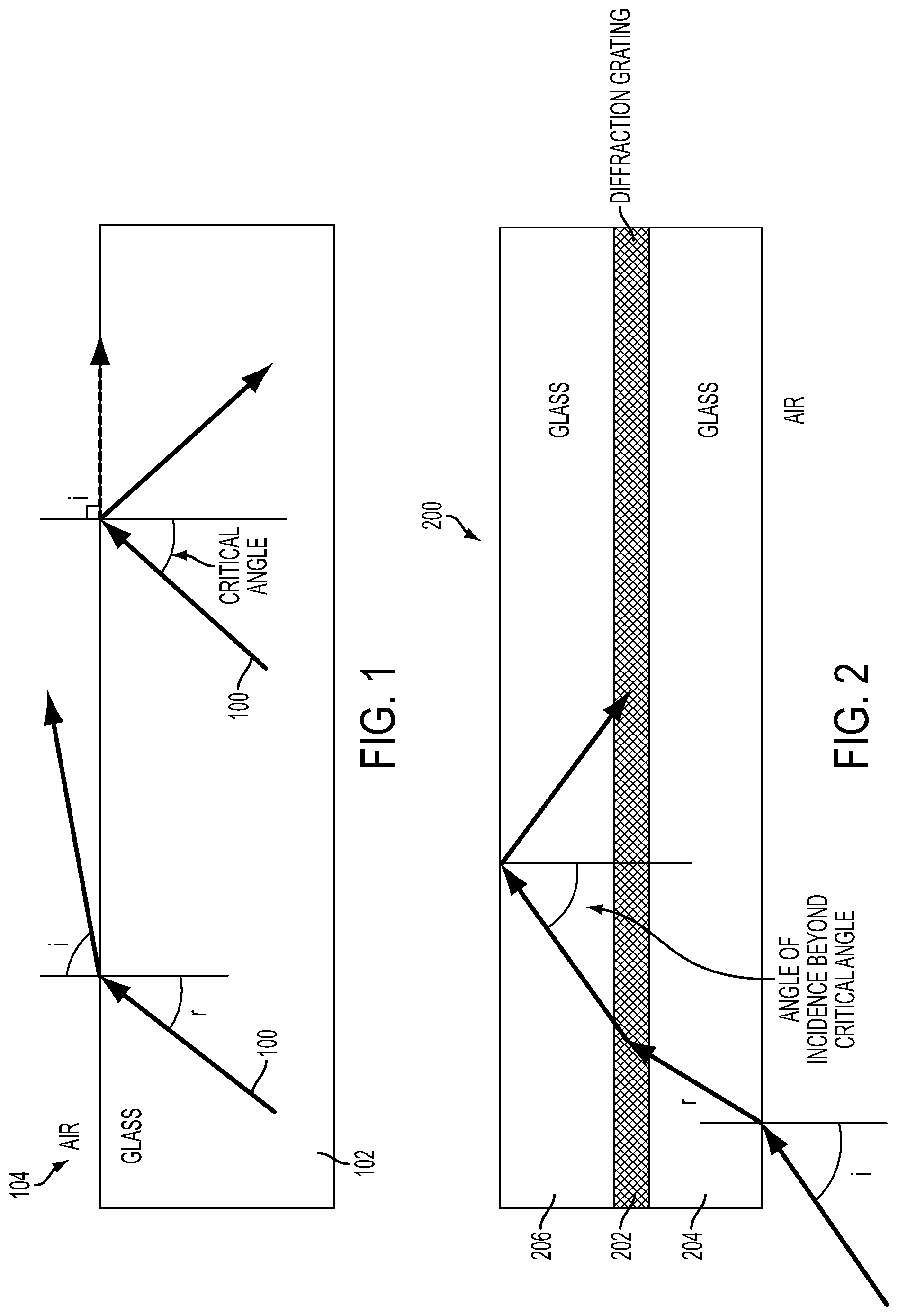
Referring to FIG. 1, a light wave 100 may pass through a glass or plastic layer 102 and an air layer 104, according to an exemplary embodiment. The refractive index of glass/plastic 102 may be found using Snell's equation: Sine i/Sine r=refractive index. The largest angle of incidence in which light wave is refracted out of glass/plastic 102 is called the critical angle (r.sub.c). In air, when i=90.degree., Sine r.sub.c=1/refractive index, so for propagation in a waveguide (parallel surfaces of optical medium) the allowable angle range is r.sub.c to r=90.degree.. Practically speaking, for substrate guided optics, the internal angle range is generally much smaller and equates to an external angle of about 20.degree. to 30.degree..
Referring to FIG. 2, light enters a substrate or waveguide 200 and is diffracted by a diffraction grating 202 between a glass layer 204 and another glass layer 206. Diffraction grating 202 adjusts the angle of the light passing through glass 204 so that the angle of the light as it meets the upper surface of glass 206 is beyond the critical angle and it reflects internally in waveguide 200. The light will then pass back through grating 202 and glass layer 204 and exit into the air at a different point than it entered glass layer 204. According to various exemplary embodiments, diffraction grating 202 may be a thick phase transmission hologram, a reflection hologram, a Bragg grating, binary or uniform optics, or another surface grating or diffractive surface.
For example, co-owned U.S. Pat. No. 5,856,842, which is herein incorporated by reference in its entirety, shows how light from a far field object (where the light is substantially collimated) can be coupled into a waveguide and out again by diffractive means, for example in a periscope. The far field object can also be created by a collimating lens in the same manner that an HMD or HUD images light from a display device, for example a CRT or flat panel display (e.g., an LCD display, a plasma display, etc.). The optics of the periscope may be used to displace the light from a collimating lens and can be used in an HMD, a HUD, or eyewear, for example a combiner in a conventional HMD or HUD.
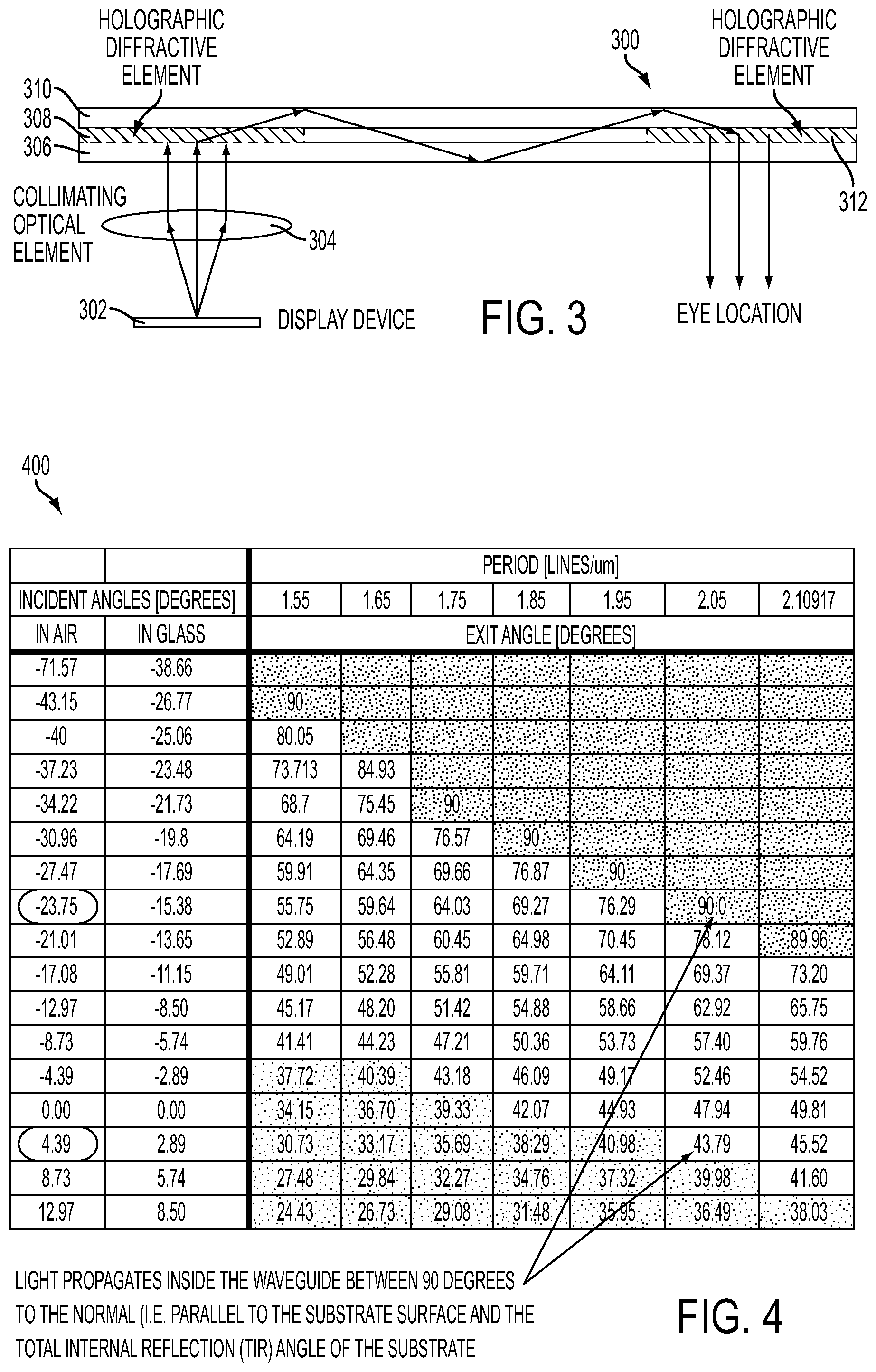
Referring to FIG. 3, a simplified holographic waveguide 300 receives light transmitted from a display device 302 and through a collimating element 304. The light passes through a glass (or optical plastic or other transparent) layer 306 and a diffractive element 308 (e.g., a holographic diffractive element), which is configured to diffract the light at a different angle. The diffracted light has an angle greater than the critical angle of a glass layer 310 and glass layer 306 and thus propagates internally to a second diffractive element 312. Element 312 is configured to diffract the light out of waveguide 300, for example to an eye location. Because the diffractive power of in-coupling diffractive surface 308 is the same as out-coupling diffractive surface 312, the input and output angles are the same. This is generally true for any wavelength and thus there may be no chromatic aberration in the system.
Light propagation may be limited within a range of angles, for example the total internal reflection (TIR) is about 41 degrees to the substrate normal for glass. This range of angles can be extended slightly using a reflective coating, but this may diminish the transparency of the substrate. Light propagation may also be limited by light parallel to the surface (90 degrees to the surface normal). Light coupled into waveguide 300 using diffractive element 308 therefore has a range of angles that relates to the power of diffractive element 308 (e.g., diffraction grating line spacing) and refraction out of element 308.
Referring to FIG. 4, these conditions have been tabulated in a chart 400 to show that the range of the external angles coupling into the waveguide or out of the waveguide may have a theoretical limit of about 30 degrees, according to an exemplary embodiment using BK-7 optical glass. Chart 400 shows an analysis of the external angles that can be employed versus the internal limits of the waveguide and how the range of external angles vary depending upon the grating spacing. Light propagates inside the waveguide (e.g., waveguide 300) between 90 degrees to the normal and the TIR angle of the substrate. In the illustrated example, the incidence angle in air at the substrate (field of view) is between -23.75 degrees and 4.39 degrees, giving a range of 28.14 degrees or less than 30 degrees.
The practical limit of the external angles is far less than 30 degrees. In another example, a limit of 20 degrees has been set for discussion purposes and as a representation of a reasonable limit for the angular bandwidth of a typical hologram. At system level, in order to expand the field of view well beyond about 20-30 degrees more than one hologram may be used. Each hologram diffracts light from a cone of external angles (e.g., about 20 degrees range) into the waveguide and propagates the light within the range of allowable angles supported by the waveguide (between 90 degrees and the TIR condition). However, the external angles of each hologram can be offset with respect to the other hologram by changing the diffractive power.
Referring to FIG. 5, a chart 500 illustrates that two holograms can couple light within the allowable angles of the substrate with external angles adding up to more than 30 or 40 degrees to expand the field of view of the system, according to an exemplary embodiment. If diffraction gratings 502 and 504 are applied, the field of view of the system in this example is expanded between about -59 degrees and about 6.57 degrees or to approximately 70 degrees (angle in air).
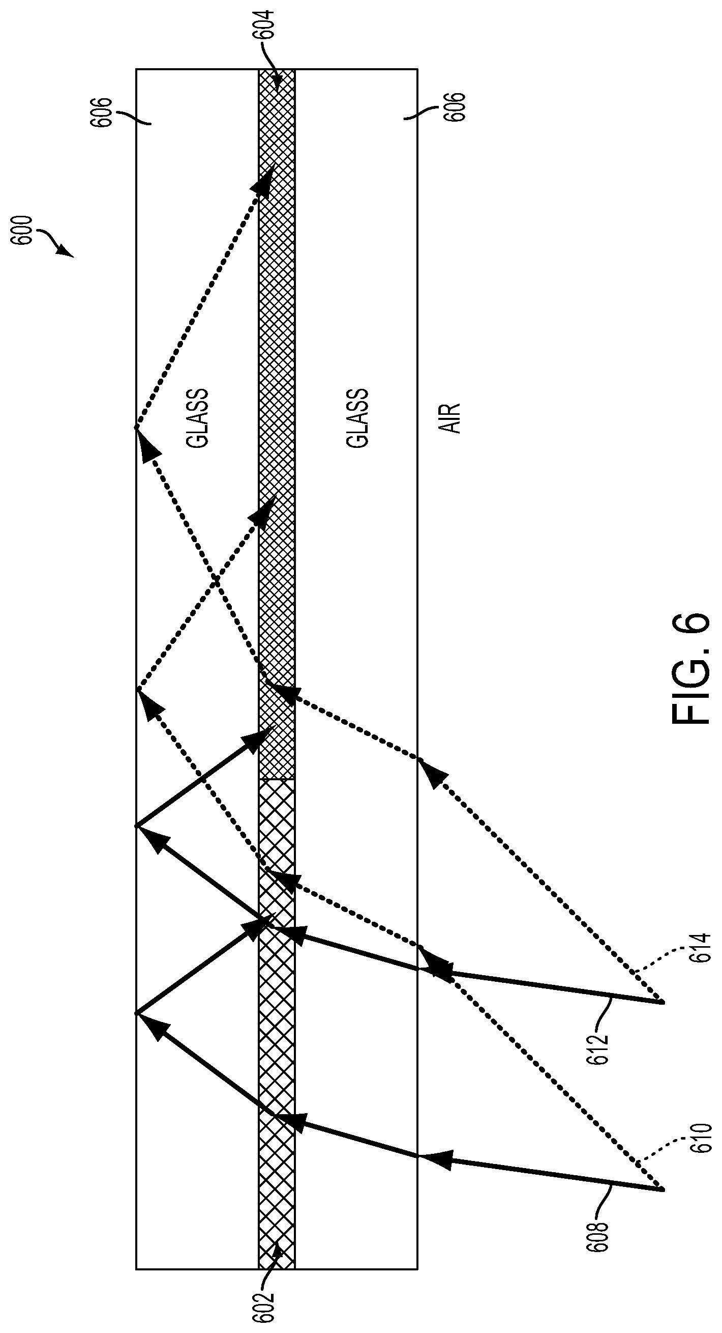
Referring to FIG. 6, a waveguide 600 includes two diffractive surfaces 602 and 604 in a substrate 606 to extend the field of view of the system, according to an exemplary embodiment. A light ray or wave 608 and a light ray 610 form a first field of view angle and both fall incident on diffractive surface 602. A light ray 612 and a light ray 614 form a second field of view angle and fall incident on diffractive surfaces 602 and 604 causing the behavior of the light to be different (shown here as diverging light rays). If the light from rays 612 and 614 hit out-coupling diffractive surface 604, the resultant image will be a double image. If the light is broad band (e.g. 50 nm from an LED), then the difference in diffractive power between in-coupling diffractive element 602 and out-coupling diffractive element 604 may also induce chromatic aberration.
Referring to FIG. 7, a waveguide 700 illustrates how in-coupling switchable diffractive elements and out-coupling diffractive elements can be paired up and switched in and out (on and off or vice versa) so that the output light does not suffer from image doubling and chromatic aberration, which would be present if trying to use non-switchable diffraction elements as discussed earlier. Waveguide 700 includes diffractive elements 702, 704, and 706 (e.g., switchable diffractive elements such as electronically switchable Bragg gratings or Holographic Polymer Dispersed Liquid Crystal (HPDLC)) in substrate 708 at an input portion and diffractive elements 710, 712, and 714 in substrate 708 at an output portion. Output diffractive elements 710, 712, and 714 have the equal and opposite diffractive power as corresponding input diffractive elements 702, 704, and 706, respectively. In the illustrated exemplary embodiment, light is received by a collimating device 716 from three different angles. The input collimating lens generates a field of view that is needed for the optical display system (e.g., HMD, HUD, eyewear, etc.). According to some exemplary embodiments, the collimating lens may be integrated with diffractive elements 702, 704, 706, while in other exemplary embodiments, the collimating lens may be separate. At any point in time, only one of each input element 702, 704, or 706 may be operational or switched on along with its corresponding output element 710, 712, or 714 and all elements may switch consecutively within the frame time of the system. Light does not couple into waveguide 700 until it hits a diffractive element (702, 704, or 706) that is operational. Therefore, only light from one angle range is coupled into waveguide 700 at any one point in time. Further, light does not couple out of the substrate until it hits the diffraction element that is operational.
According to the illustrated example, a single parallel beam of light shown by dashed lines hits diffraction surface 702 and is diffracted into waveguide 700 until it hits complimentary diffractive surface 710 and is diffracted out of waveguide 700 at the same angle as it enters waveguide 700. Because the input diffractive power is equal and opposite to the output diffractive power no chromatic aberration is induced in the system. It is noted that while the FIGURE illustrates use of three input and output switchable diffractive elements, according to other exemplary embodiments, more or fewer than three switchable diffractive elements may be used. It is also noted that while the FIGURE illustrates reception and output of light at three different angles, the figure does not include the light in the range between the three field angles shown. The light incident on each of the diffractive surfaces are in a range limited by the geometric limits described herein for a single fixed diffractive surface and are therefore in a range tabulated in FIG. 4 and limited to about 30 degrees.
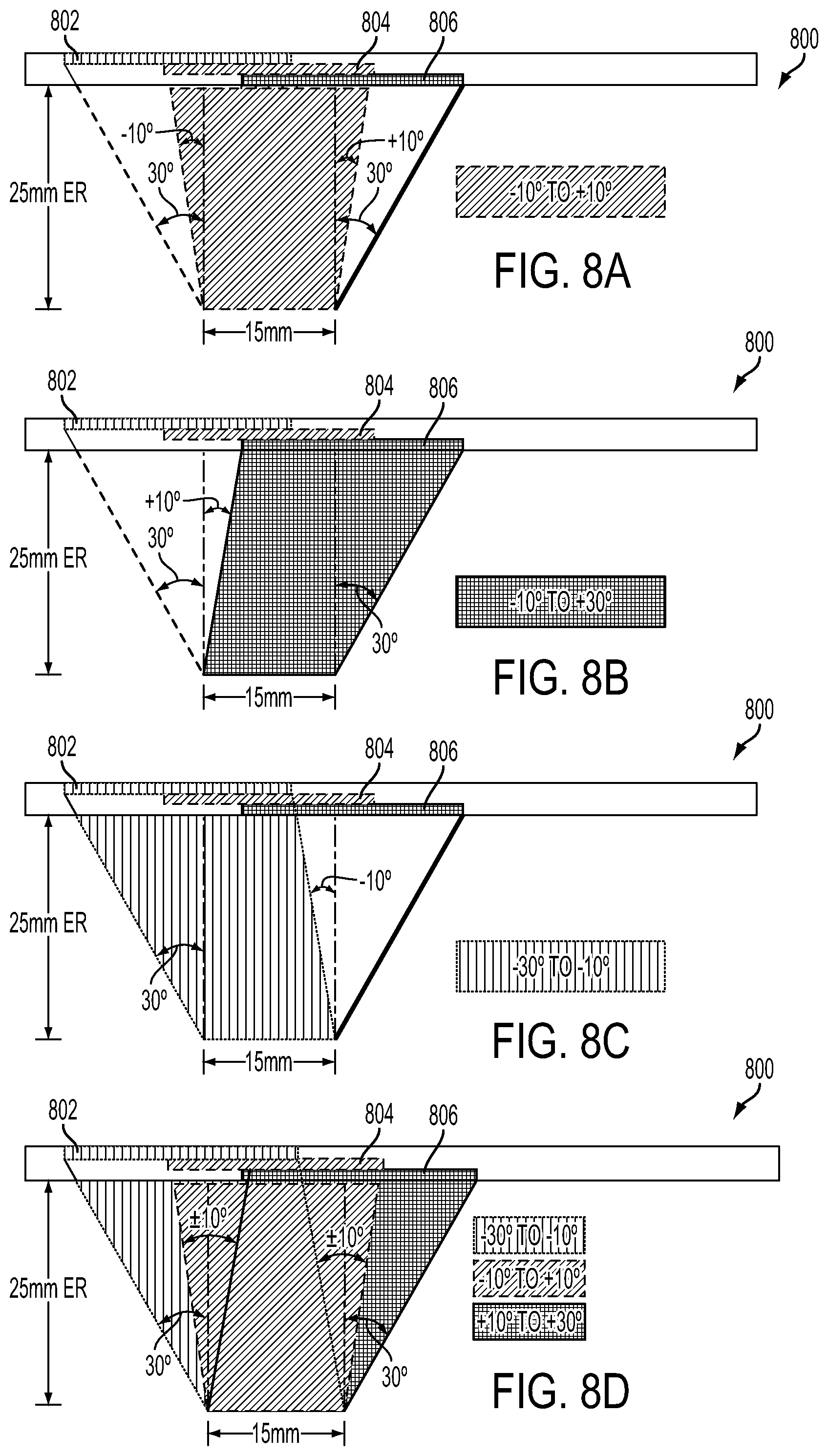
Referring to FIGS. 8A-8D, a first order geometry of output holograms for a waveguide 800 is illustrated, according to an exemplary embodiment. For purposes of this example, the exit pupil of the system was set at about 15 mm (which is generally regarded as the minimum acceptable exit pupil of an HMD or eyewear although according to other exemplary embodiments exit pupils much greater than 15 mm may be used) with an eye-relief of about 25 mm (the minimum requirement for wearing aviator spectacles). The first order geometry plots a 60 degree field of view using three holograms 802, 804, and 806, each with a field of view of about 20 degrees. FIG. 8A shows the first order geometry for the central 20 degrees (plus and minus 10 degrees from normal), FIG. 8B shows the right 20 degrees (10 to 30 degrees from the left normal), FIG. 8C shows the left 20 degrees (-10 and -30 degrees from the right normal), and FIG. 8D shows the full 60 degrees of the holographic waveguide display with three overlapping holograms. The practical implementation of using multiple switchable diffractive surfaces in an HMD, HUD, or eyewear therefore includes overlapping switchable diffractive surfaces. This includes the illustration of FIG. 7, which shows a simplified version where the diffractive surfaces are adjacent to each other.
For an extended field of view and an extended exit pupil, the footprint of the light rays for exemplary 20 degree sections overlaps at waveguide 800. The overlap may be decreased with increasing eye-relief and may be increased with increasing exit pupil size. For example, if the system has an exit pupil of 30 mm, then the overlap will be significant. Overlapping holograms cannot be employed within the same waveguide using conventional holographic material because the rays for each hologram would be indistinguishable from one another since they fall within the same range of internal waveguide angles.
According to some exemplary embodiments, multiple holograms that overlap with each other and are separated by an air space may be used, however, implementation of a mechanism for a curved visor or much greater field of view may be difficult and not lend itself to a low mass and mechanically stable solution. According to other exemplary embodiments, Switchable Bragg Gratings (SBG) (e.g., electronically switchable Bragg gratings) may be used as the diffractive element, for example as developed by SBG Labs, Inc. of Silicon Valley, Calif. According to other exemplary embodiments, switchable transmission holograms or switchable reflection holograms may be used to develop wider fields of view.
A waveguide (e.g., waveguide 700 or 800) may include multiple holograms (e.g., holograms 702,704, and 706 or holograms 802, 804, and 806) of different powers. An SBG stack can be used that can be switched sequentially to build up the field of view of the optics This allows a setup of overlapping holograms as illustrated in FIGS. 7 and 8.
Referring to FIG. 9, a waveguide system 900 may include multiple stacks of SBG holograms 902, 904, and 906 that are at least similar to each other, according to an exemplary embodiment. Such a system 900 may be used to generate color displays in sequential mode. Frame sequential color and frame sequential wide field of view have similar coordination between the display data, the illumination source, and the SBGs. Each SBG stacks 902, 904, and 906 may be used to propagate a different color, for example, red, blue, and green. At any given point in time, one set of input and output holograms may be switched on to diffract light of a specific color and all holograms will switch within the frame time of the system at a rate sufficient so a human eye will not perceive flicker (e.g., about 16 milliseconds). According to other exemplary embodiments, different color schemes may be used or more or fewer than three switchable diffractive stacks may be used.
Referring to FIG. 10, while the waveguides have been illustrated as having single rows of diffractive elements thus far, according to other exemplary embodiments, a waveguide 10000 may include an in-coupling surface 1002 and an out-coupling diffractive surface 1004 that are paired up in a two dimensional array and have equal and opposite diffractive power. The input light may be generated using a collimating lens placed at exit pupil distance from the in-coupling diffractive array. The exit pupil of the lens may be of similar dimensions as for an HMD, HUD, or eyewear display system. The diffractive arrays concept may be used with broadband light sources and so lasers are not required in order to make the system work. It is noted that as in FIG. 8, due to the first order geometry of exit pupil and eye relief and the desire to have a contiguous field of view, overlapping switchable diffractive devices may be used in a practical implementation for an HMD, HUD, or eyewear.
According to other exemplary embodiments, the diffractive power on the input coupling diffractive elements can include additional diffractive power that can be used to color correct chromatic aberrations in the collimating lens. According to some exemplary embodiments, the waveguides described above may be used with a device that can be controlled to illuminate pixels at specific times. According to some exemplary embodiments, the waveguide system can utilize a beamsplitter in the middle of the sandwich to expand the exit pupil. Therefore, the input lens may be much smaller than for the exit pupil.
According to various exemplary embodiments, various light sources may be used to provide light waves to the waveguides described above. For example, a broad band light source such as an LED may be used with holographic waveguide displays. Chromatic dispersion induced by high power diffractive elements generally need to be negated
References
D00000
D00001
D00002
D00003
D00004
D00005
D00006
D00007
D00008
XML
uspto.report is an independent third-party trademark research tool that is not affiliated, endorsed, or sponsored by the United States Patent and Trademark Office (USPTO) or any other governmental organization. The information provided by uspto.report is based on publicly available data at the time of writing and is intended for informational purposes only.
While we strive to provide accurate and up-to-date information, we do not guarantee the accuracy, completeness, reliability, or suitability of the information displayed on this site. The use of this site is at your own risk. Any reliance you place on such information is therefore strictly at your own risk.
All official trademark data, including owner information, should be verified by visiting the official USPTO website at www.uspto.gov. This site is not intended to replace professional legal advice and should not be used as a substitute for consulting with a legal professional who is knowledgeable about trademark law.